
hysteresis current control technique for three phase induction motor
i
HYSTERESIS VOLTAGE CONTROL TECHNIQUE FOR THREE PHASE
INDUCTION MOTOR (MATLAB SIMULINK AND ARDUINO)
MOHD SAIFUL NAJIB B. ISMAIL @ MARZUKI
A project report submitted in partial
fulfillment of the requirement for the award of the
Degree of Master Of Electrical Engineering
Faculty of Electrical Engineering
Universiti Tun Hussein Onn Malaysia
JANUARY 2014

iv
ABSTRACT
This project describes a controller for three phase induction motor. Induction motor is
an electromechanical actuator widely used as due to reliable and relatively low
maintenance cost. However, the control problem of the induction motor is complex due
to the nonlinearities, the load torque perturbation, and the parameter uncertainties. An
element that include in this project is voltage control, which is to control the voltage fed
from three phase inverter to three phase induction motor. Hysteresis controller has been
used in this project to minimize the voltage error. Hysteresis controller is seen as an
input–output phase lag. The implementation of designed hysteresis controller is
performed in simulation using MATLAB Simulink. On the other side, the hardware will
be setup to observe and analyze the model.

v
ABSTRAK
Projek ini menerangkan pengawal untuk motor aruhan tiga fasa. Motor aruhan adalah
sebuah penggerak elektromekanikal yang digunakan secara meluas kerana kos
penyelenggaraan yang rendah dan boleh dipercayai. Walau bagaimanapun, masalah
kawalan motor aruhan adalah kompleks kerana tidak linear, gangguan tork beban dan
parameter yang tidak menentu. Elemen yang dimasukkan dalam projek ini adalah
kawalan voltan, yang mahu mengawal voltan dari inverter tiga fasa ke motor aruhan
tiga fasa. Pengawal histeresis telah digunakan dalam projek ini untuk mengurangkan
ralat voltan. Pengawal histeresis dilihat sebagai mundur fasa input–output. Pelaksanaan
histeresis direka sebagai pengawal dilakukan dalam simulasi menggunakan MATLAB
Simulink. Di samping itu, perkakasan disediakan dan eksperimen dijalankan untuk
memerhati dan menganalisis model tersebut.

vi
CONTENTS
TITLE i
DECLARATION ii
ACKNOWLEDGEMENT iii
ABSTRACT iv
CONTENTS vi
LIST OF FIGURE ix
LIST OF TABLE xii
LIST OF SYMBOLS AND ABBREVIATIONS xiii
CHAPTER 1 INTRODUCTION 1
1.1 PROJECT BACKGROUND 1
1.2 PROBLEM STATEMENT 3
1.3 OBJECTIVE 4
1.4 SCOPE 4
CHAPTER 2 LITERATURE REVIEW 5
2.1 INDUCTION MOTOR 5
2.1.1 THREE PHASE INDUCTION MOTOR 5

vii
2.2 INVERTER 7
2.2.1 THREE PHASE INVERTER 8
2.2.2 VOLTAGE SOURCE INVERTER 9
2.3 PASSIVE CONTROL 9
2.3.1 RELAY CONTROLLER 10
2.3.2 SLIDING MODE CONTROLLER 11
2.3.3 HYSTERESIS CONTROLLER 13
2.3.3.1 PROPOSED CONTROLLER (HYSTERESIS
CONTROLLER 14
2.4 ARDUINO 15
2.5 ADC AND DAC CONVERTER 18
CHAPTER 3 METHODOLOGY 20
3.1 BLOCK DIAGRAM OF THE PROJECT 20
3.2 THE PROJECT FLOWCHART 21
3.3 PROJECT DESIGN 22
3.3.1 THREE PHASE INVERTER DESIGN 22
3.3.2 GATE DRIVER DESIGN 24
3.3.3 CONTROLLER DESIGN 25
3.3.3.1 ANALOG TO DIGITAL CONVERTER DESIGN 26
3.3.3.2 DIGITAL TO ANALOG CONVERTER DESIGN 27
3.3.3.3 HYSTERESIS CONTROLLER DESIGN 28

viii
3.3.4 VOLTAGE SENSOR DESIGN 29
CHAPTER 4 RESULT AND ANALYSIS 31
4.1 SIMULATION RESULT AND ANALYSIS 32
4.2 OPEN LOOP RESULT AND ANALYSIS 39
4.3 CLOSED LOOP RESULT AND ANALYSIS 43
4.4 CLOSED LOOP RESULT FOR 10V AND 30V CLOSED LOOP 45
4.4.1 CLOSED LOOP RESULT FOR 10V 45
4.4.2 CLOSED LOOP RESULT FOR 30V 47
CHAPTER 5 CONCLUSIONS 50
5.1 CONCLUSION 50
5.2 FUTURE WORKS 51
REFERENCES 52
APPENDIX A 55
APPENDIX B 57
APPENDIX C 60
APPENDIX D 61
APPENDIX E 64

ix
LIST OF FIGURE
2.1 Three phase induction motor. 6
2.2 Three phase full bridge inverter. 8
2.3 Leg voltage waveform of a three-phase 8
2.4 SPDT relay. 10
2.5 Boundary layer 12
2.6 Hysteresis voltage control operation waveform. 15
2.7 The Arduino Uno 17
2.8 The ADC and DAC function 19
3.1 The project block diagram 20
3.2 Project flowchart 21
3.3 The three phase inverter in PROTEUS 22
3.4 The hardware of three phase inverter 23
3.5 The gate driver in PROTEUS software 24
3.6 The hardware of the gate driver 25
3.7 The model of controller design in MATLAB Simulink. 25
3.8 The ADC graph. 26
x
3.9 The DAC graft. 27
3.10(a) Hysteresis controller block 28
3.10(b) The PWM produced in phase A 28
3.11(a) The transformer with circuit of offset voltage 29
3.11(b) The waveform of the transformer and its offset voltage 29
4.1 Hysteresis controller model for simulation. 32
4.2 The inverter, transformer and filtering model 33
4.3 The filter block and the filter block function parameter. 34
4.4 The analog signal , ADC output and Dac output. 34
4.5 The three phase component for reference voltage signal 35
4.6 The voltage error after hysteresis controller 35
4.7 The PWM and invert PWM for phase A 36
4.8 The output voltage inverter for three phases 36
4.9 The output voltage filter in three phases ( 37
4.10 The output voltage of transformer 37
4.11 The output voltage filter of the output transformer 38
4.12 The open loop model 39
4.13 The output PWM and invert PWM of gate driver 40
4.14 The output voltage of gate driver 40
4.15 The output voltage of inverter 41
4.16 The output voltage of transformer 41

xi
4.17 The output voltage of transformer with offset 42
4.18 The closed loop MATLAB Simulink model 43
4.19 The output voltage from inverter 44
4.20 The output voltage of transformer 44
4.21 The output voltage of transformer with offset. 45
4.22 The output of the inverter. 45
4.23 The output of the transformer. 46
4.24 The output voltage of the transformer with offset. 46
4.27 The output voltage of the inverter. 47
4.28 The output voltage of the transformer 47
4.29 The output voltage of the transformer with offset. 47

xii
LIST OF TABLE
2.1 The summary of the Arduino Uno 16
2.2 The Arduino pin assignment. 18
4.1 The result of 20V open loop and 10V, 20V and 30V closed loop 48

xiii
LIST OF SYMBOLS AND ABBREVIATIONS
V - Voltage
DC - Direct current
AC - Alternating current
Vac - Alternating current voltage
VSI - Voltage source inverter
CSI - Current source inverter
PID - Proportional integral derivative
PWM - Pulse width modulation
DSP - Digital signal processing
r.m.f. - Rotating magnetic field
DFO - Direct field-oriented
FFT - Fast fourier transform
IC - Integrated circuit
SMC - Sliding mode controller
DTC - Direct torque ratio
USB - Universal serial bus

xiv
ADC - Analog to digital converter
DAC - Digital to analog converter
IPM - Interior permanent magnet
ICSP- - In circuit serial programming

1
CHAPTER 1
INTRODUCTION
1.1 PROJECT BACKGROUND
Induction motor is widely used in industry because of its reliability and low cost, either
single phase or three phases. However, three phases induction is the most interesting
and has attracted the attention of many researchers because of induction motor is
strongly nonlinear [1]. Many controllers have been developed, that can be divided into
two classifications, passive and adaptive power control. The example for passive power
control is hysteresis, relay and sliding mode control and for adaptive power control is
PID, fuzzy, and P-resonant controller [2, 3]. Each of them has their advantages, such as
simple structure and low maintenance cost [4].
Inverter is a device which supplies variable frequency of power supply on equipments
[5]. Base on this function, motor revolution speed can be controlled and it leads to
reduce energy consumption. Basically the motor is driven by the inverter. The induction
current is generated on the cage according to the rotating magnetic field, so the rotor
will be driven accordingly without detecting rotor position.
Power electronics have moved along with these developments with such things as
digital signal processors being used to control power systems. An Inverter is basically a

2
converter that converts DC to AC power. A voltage source inverter (VSI) is one that
takes in a fixed voltage from a device, such as a dc power supply, and converts it to a
variable frequency AC supply [6].
Inverters that use PWM switching techniques have a DC input voltage that is usually
constant in magnitude. The inverters job is to take this input voltage and output ac
where the magnitude and frequency can be controlled.
Many applications that require an inverter use three phase power. The example is an ac
motor drive. One option for a three phase inverter is to use three separate single phase
inverters but vary their output by 120° [3]. The three phase inverter setup consists of
three legs, one for each phase. In three phase inverters PWM is used in the same way
as it is before except that it much be used with each of the three phases. When
generating power to three different phases one must make sure that each phase is equal,
meaning that it is balanced.
Induction machine has the same physical stator as a synchronous machine with a
different rotor construction [7, 8]. Induction machines can be operated as both motors
and generator. Induction machines are by far the most common type of motor used in
industrial, commercial or residential settings.
So the inverter is one of the solutions to control the induction motor. An inverter can
easily control the speed of the three-phase induction motor. The main principle is to
switch the motor on and off very rapidly, much more rapidly than any mechanical
switch could do. The AC output of the inverter can be controlled both in amplitude and
frequency that commit the requirements of induction motor at any desired point of
operation [9]. Speed and torque can now be controlled independently of each other. The
switching operation in inverter is connect the power switches when line voltage is low
and disconnect when it is high. Therefore, the energy can go either way even though the
line voltage is constant.
In many applications of the induction motor, high performance voltage control is one of
the fundamental issues. The purpose of the voltage control is to control the flux or the
torque of the induction motor. Therefore, many researchers and practitioners had

3
developed various controller algorithms to improve the response of induction motor.
But only a few of them had included the Arduino into their research. Basically, Arduino
is an embedded device that can be use as a digital signal processing (DSP) [10].
1.2 PROBLEM STATEMENT
The recent advances in the area of field-oriented control that bring the rapid
development and cost reduction of power electronics devices for three phase induction
motor give more economical for many industrial applications. However, the control
problem of the induction motor is complex due to the nonlinearities.
The principle of an electric motor is always to create a rotary movement by attracting
and repelling magnetic forces. Therefore the current is excessively high at the first
instance of switching on when the motor is not yet running. As the motor speeds up, this
induced voltage increases [11]. In fact when exceeding the speed where the applied
voltage and the mains voltage are equal the motor will generate a higher voltage than
that found in the line. Current will flow the other way round, and the motor has inversed
its function as generator.
The challenge in induction motor is to run at the desired speed the voltage generated in
the motor is the same as the applied operating voltage. The processes that drive the
induction motor are hard because it has electric magnets in both side, the stator and in
the rotor. The rotor windings are shorted and act like the secondary windings of a
transformer. The magnetic field rotating in the stator induces a current in the shorted
rotor windings, which then generates its own magnetic field [10].

4
1.3 OBJECTIVE
The objectives of this project are listed as follows:
1. To develop the Hysteresis Controller approach for motor torque control.
2. To simulate and design the Hysteresis Controller model by using MATLAB
Simulink.
3. To analyze the Hysteresis Controller.
4. To implement hardware of induction motor drives that is voltage control, using
Hysteresis Controller carried by Arduino embedded devices.
1.4 SCOPE
In this project the scope of work will be undertaken in the following developmental
stages:
1. Study of the control system of induction motor for voltage control based on
Hysteresis Controller.
2. Perform simulation of Hysteresis Controller. This simulation will be carried out
on MATLAB platform with Simulink as it user interface.
3. Development of the target MATLAB Simulink model to Arduino and
implements the hardware of voltage control of induction motor for Hysteresis
Controller.

5
CHAPTER 2
LITERATURE REVIEW
2.1 INDUCTION MOTOR
An electrical motor is such an electromechanical device which converts electrical
energy into a mechanical energy. In simple words, the electrical motor is a device that
produces rotational force. The induction motor is one of the electrical motor.
2.1.1 THREE PHASE INDUCTION MOTOR
A three phase induction motor is one of an electric motor that converts electrical energy
into a mechanical energy which is then connected with different load, also described as
transformer type. The three phase induction motors are most widely used for industrial
applications mainly because they do not require a starting device. The operating
principle of a three phase induction motor is based on the production of r.m.f.[12]. It
has a stator that carries a three phase winding and rotor that carries a short circuited
winding. Only the stator winding is fed from three phase supply. The rotor winding
derives its voltage and power from the externally energized stator winding through
electromagnetic induction. The advantages and disadvantages of the three phase
induction motor are stated below:
Advantages:
(i) It has simple and rugged construction.
(ii) It is relatively cheap.
(iii) It requires little maintenance.
(iv) It has high efficiency and reasonably good power factor.
(v) It has self starting torque.

6
Disadvantages:
(i) It is essentially a constant speed motor and its speed cannot be changed easily.
(ii) Its starting torque is inferior to DC shunt motor.
Figure 2.1: Three phase induction motor.
Three phase induction motor is very popular electrical and mechanical equipment and
get more attention from researchers and practitioners due to the nonlinearities.
In paper [13] had presented novel field-weakening scheme for the induction machine.
The proposed algorithm, based on the voltage control strategy, ensures the maximum
torque operation over the entire field-weakening region without using the machine
parameters. Also, they had introduced the direct field-oriented (DFO) control, which is
insensitive to the variation of machine parameters in the field-weakening region, the
drive system can obtain robustness to parameter variations. Lastly, they founded
Experimental results for the laboratory induction motor drive system confirms the
validity of the proposed control algorithm.
In paper [14] had presented a direct field-oriented induction motor drive with a sliding
mode controller. In this paper, they had considered about rotor speed estimation from
measured stator terminal voltages and currents. Besides that, they used function “sat” to
limit chattering effects. Then they had evaluated the consistency and performance of the
proposed control technique.

7
In paper [15] had proposed adaptive sliding-mode control system to control the position
of an induction motor drive. The sliding mode control presents an adaptive switching
gain had been designed to relax the requirement for the bound of uncertainties. They
also performed Lyapunov theory in order to guarantee the closed loop stability. Then
they had discussed about simulation results of the proposed controller.
In paper [16] had presented hysteresis control method for three-phase current controlled
voltage-source PWM inverters. It minimizes interference among phases, thus allowing
phase-locked loop (PLL) control of the modulation frequency of inverter switches. Then
they had discussed about control theory, and described the controller implementation.
Design criteria are also given. The results of experimental tests show excellent static
and dynamic performance.
2.2 INVERTER
The inverter performs the opposite function of a rectifier, also known as dc to ac
converter. An inverter is a device that takes direct current (DC) and changes it to
alternating current (AC) [6]. The electrical inverter is a high-power electronic oscillator,
can classified as voltage source inverters (VSIs) and current source inverters (CSIs). It
can be dividing into 2, which are single phase inverter and three phase inverter. It
depends on the user load requirement whether in the industrial applications,
transportations and home appliances. The output voltage of an inverter has a periodic
waveform which is not purely sinusoidal, but with number of techniques it can be
designed to closely approximate to this desired waveform. Example of the technique is
to put lowpass filter. In most circumstances, three phase inverter offered better
performances as compared to single-phase inverter. Power semiconductors switches are
the basic component of the inverter. In this paper, the three phase inverter will be
proposed.

8
2.2.1 THREE PHASE INVERTER
A three-phase inverter will cover medium to high power applications. The three-phase
dc/ac voltage source inverters are extensively being used in motor drives to generate
controllable frequency and ac voltage magnitudes using various pulse width modulation
(PWM) strategies. The standard three-phase inverter shown in figure 2.2 has six
switches. The purpose of the topology is to provide a three-phase voltage source, where
the amplitude, phase and frequency of the voltages can be controlled.
Figure 2.2: Three phase full bridge inverter.
Figure 2.3: Leg voltage waveform of a three-phase.
In figure 2.3, one inverter leg's state changes after an interval of 60° and their state
remains constant for 60° interval. Thus it follows that the leg voltages will have six
distinct and discrete values in one cycle (360°).

9
2.2.2 VOLTAGE SOURCE INVERTER
Generally there were two types of inverter topology, named as Voltage Source Inverter
and Current Source Inverter. Voltage waveform is the independently controlled AC
output in the VSI topologies. Meanwhile, in CSI topologies, the independently
controlled AC output is a current waveform. VSI can be further divided into three
categories which are PWM Inverter, Square Wave Inverter and Single-phase Inverters
with Voltage Cancellation. The structure of VSI is more widely used in the industrial
application due to the voltage source requirement
In paper [5] had invented a three phase inverter producing a stepped voltage between
each two output terminal which approximates the sinusoidal form. She had included
two three phase inverter system of the type comprising pairs of parallel arranged
controllable rectifier and three transformers each have a primary winding and two
secondary windings.
In paper [16] had proposed a simple, novel alternative approach for a variable-
hysteresis-band current controller which uses feed forward and feedback techniques to
achieve constant switching frequency with good dynamic response. They said the
method is easily implemented in hardware, the resultant controller Is easily tuned to a
particular load, and has good immunity to variations in motor parameters and dc supply
voltage. Lastly, they presented an analytical, hardware implementation, simulation, FFT
analysis and experimental results.
2.3 PASSIVE CONTROL
There is several type of controller that has been made from researcher. It‟s given the
positive growth in controller design and makes the power electronics more interesting to
explore. The type of the controller is as follows:

10
2.3.1 RELAY CONTROLLER
In the early days of control engineering, relays were commonly used as they provided a
cheap form of power amplification. The different between switching nonlinearities and
other nonlinearities is their input does not control the output continuously but only
determines the instant of switching. The input has not control of output between
switching instants. This feature will allows a unique theory to develop for analyzing
limit cycles in feedback loops with relays elements [17].
In paper [17] are considered the relay control systems with time delay. They had found
that the time delay does not allow realizing an ideal sliding mode, but implies
oscillations, whose stability is determined by oscillation frequency. They had
considered the problem of stability of steady modes in three main cases autonomous,
quasi autonomous and periodic. Lastly, they had investigated the structural stability of
steady modes in the periodic case.
Figure 2.4: SPDT relay.
In figure 2.4 shows that the relay component. There are two commonly used types of
relay which are normally open (NO) and normally close (NC). The advantages and
disadvantages of relay are stated below:
Advantages of relays:
Relays can switch AC and DC, transistors can only switch DC.
Relays can switch higher voltages than standard transistors.
Relays are often a better choice for switching large currents (> 5A).
Relays can switch many contacts at once.

11
Disadvantages of relays:
Relays are bulkier than transistors for switching small currents.
Relays cannot switch rapidly (except reed relays), transistors can switch many
times per second.
Relays use more power due to the current flowing through their coil.
Relays require more current than many ICs can provide, so a low power
transistor may be needed to switch the current for the relay's coil.
2.3.2 SLIDING MODE CONTROLLER
Sliding mode control is one of the controllers suitable for nonlinear system such as
induction motor. Background of this controller is founded in the former Soviet Union as
a variable structure control system, and appeared outside Russia in the mid 1970s. The
concept of sliding mode is proposed by Russian mathematician, Lyapunov and had
discussed his theory about nonlinear systems. The main of the sliding mode controller is
to adjust feedback by previously defining a surface. The system which is controlled will
be forced to that sliding surface, then the behavior of the system slides to the desired
equilibrium point. The main feature of this control is that we only need to drive the
error to a switching surface. When the system is in sliding mode, the system behavior is
not affected by any modeling uncertainties or disturbances [14].
There is definition of terms in sliding mode controller:
(i) State Space – An n-dimensional space whose coordinate axis consist of the x1
axis, x2 axis until xn axis.
(ii) State trajectory- A graph of x(t) verses t through a state space.
(iii) State variables – The state variables of a system consist of a minimum set of
parameters that completely summarize the system‟s status.
(iv) Disturbance – Completely or partially unknown system inputs which cannot be
manipulated by the system designer.
(v) Sliding Surface – A line or hyperplane in state-space which is designed to
accommodate a sliding motion.

12
(vi) Sliding Mode – The behavior of a dynamical system while confined to the
sliding surface.
(vii) Reaching phase – The initial phase of the closed loop behavior of the state
variables as they are being driven towards the surface.
Figure 2.5: Boundary layer [23].
In paper [4] had proposed integrated sliding mode controller to achieve high
performance speed control of an induction motor. A flux SMC is established first to
achieve fast direct flux control and then a speed SMC is presented to enhance speed
control by the direct torque method. Both of the SMC are designed in light of
predetermined load disturbance and parameter uncertainties. Then they had verified the
effectiveness of the proposed control by simulation results and compared with the direct
torque control (DTC) and proportional-integral direct torque control (PIC) approaches.
The main feature of sliding mode controller is that we only need to drive the error to a
switching surface.
Consider the nonlinear system is:

13
The system in the state space structure is:
[
] [ ] [
]
Where [ ], [
] [ ] [
], [
], and [
]
The switching surface is then defined by:
( )
The goal of sliding mode controller is to keep the system motion on the manifold,
( ) . The state trajectory of the sliding mode controller can be control with:
Where is the tracking error, is the desired state vector and is the state vector. In
order to ensure the stability of sliding mode controller, the Lyapunov stability criteria
will be adapted:
( )
( )
2.3.3 HYSTERESIS CONTROLLER
The other word of hysteresis is deficiency or lagging behind [18]. Hysteresis refers to
systems that have memory, where the effects of the current input to the system are
experienced with a certain lag. Hysteresis phenomena occur in magnetic materials,
ferromagnetic materials and ferroelectric materials, as well as in the elastic, electric,
and magnetic behavior of materials, in which a lag occurs between the application and
the removal of a force or field and its subsequent effect. Electric hysteresis occurs when
applying a varying electric field and elastic hysteresis occurs in response to a varying
force.
In a deterministic system with no dynamics or hysteresis, it is possible to predict the
system's output at an instant in time, given only its input at that instant in time.

14
Hysteresis control is not possible to predict the output without knowing the system's
current state, and there is no way to know the system's state without looking at the
history of the input. This means that it is necessary to know the path that the input
followed before it reached its current value [18]. In electrical engineering, Hysteresis
can be used to filter signals so that the output reacts slowly by taking recent history into
account.
In paper [6] had presented a hysteresis controller method for three-phase current
controlled voltage-source PWM inverter. They had concluded that the control
minimizes interference among phases, thus allowing phase-locked loop (PLL) control
of the modulation frequency of inverter switches. They also discussed about the control
theory and described the controller implementation.
2.3.3.1 PROPOSED CONTROLLER (HYSTERESIS CONTROLLER)
Hysteresis controller derives the switching signals of the inverter power switches in a
manner that reduces the voltage error. The switches are controlled so that it follows the
reference. The voltage ramping up and down between two limits is illustrated in figure
2.6. [19] When the voltage through the induction motor exceeds the upper hysteresis
limit a negative voltage is applied by the inverter to the induction motor. This causes the
voltage in the induction motor to decrease. Once the voltage reaches the lower
hysteresis limit a positive voltage is applied by the inverter to the induction motor and
this causes the voltage to increase and the cycle repeats.
The voltage controllers of the three phases are designed to operate independently. Each
voltage controller determines the switching signals to the inverter. The switching logic
for phase A is formulated as below:
If Va < (Varef -HB) upper switch (G1) is OFF and lower switch (G4) is ON
If Va < (Varef +HB) upper switch (G1) is ON and lower switch (G4) is OFF
In the same action, the switching of phase B and C are derived but in different phase
shift that is phase B in 120° shift and phase C in 240° shift.

15
Figure2.6. Hysteresis voltage control operation waveform.
In paper [20] had described an adaptive hysteresis-band current control method where
the band is modulated with the system parameters to maintain the modulation frequency
to be nearly constant. Although the technique is applicable to general ac drives and
other types of load, an interior permanent magnet (IPM) synchronous machine load is
considered. Then systematic analytical expressions of the hysteresis band are derived as
functions of system parameters. Lastly, a voltage-fed current-controlled PWM inverter
has been simulated on computer to study the performance of the proposed method.
2.4 ARDUINO
Arduino is one of the embedded devices that are increasing in used. It‟s very popular for
beginner and has attracted the people who are already working with other
microcontrollers. Arduino is best known for its hardware, but we also need software to
program that hardware. Both the hardware and the software are called Arduino [10].
The combination enables us to create projects that sense and control the physical world.
Arduino is easy to used and explore because of it is open source. In this project,
Arduino is used to create prototypes, to carry out the duty of controller to control the
switching of three phase inverter.
16
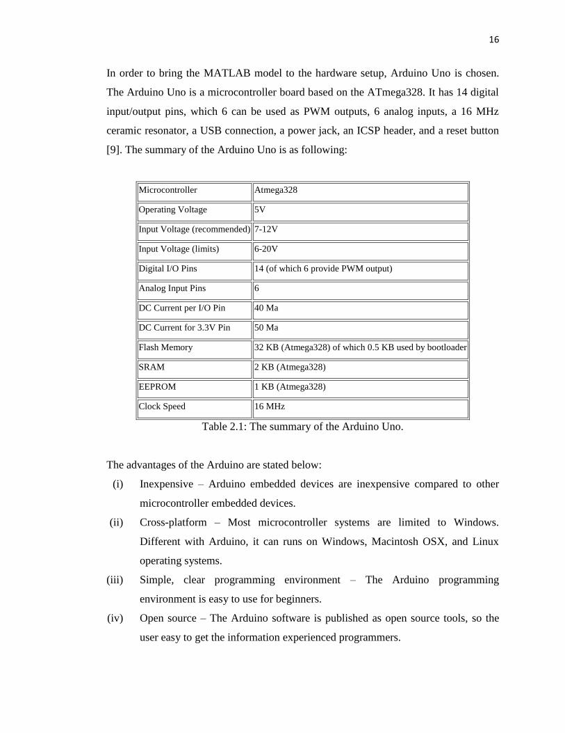
In order to bring the MATLAB model to the hardware setup, Arduino Uno is chosen.
The Arduino Uno is a microcontroller board based on the ATmega328. It has 14 digital
input/output pins, which 6 can be used as PWM outputs, 6 analog inputs, a 16 MHz
ceramic resonator, a USB connection, a power jack, an ICSP header, and a reset button
[9]. The summary of the Arduino Uno is as following:
Microcontroller Atmega328
Operating Voltage 5V
Input Voltage (recommended) 7-12V
Input Voltage (limits) 6-20V
Digital I/O Pins 14 (of which 6 provide PWM output)
Analog Input Pins 6
DC Current per I/O Pin 40 Ma
DC Current for 3.3V Pin 50 Ma
Flash Memory 32 KB (Atmega328) of which 0.5 KB used by bootloader
SRAM 2 KB (Atmega328)
EEPROM 1 KB (Atmega328)
Clock Speed 16 MHz
Table 2.1: The summary of the Arduino Uno.
The advantages of the Arduino are stated below:
(i) Inexpensive – Arduino embedded devices are inexpensive compared to other
microcontroller embedded devices.
(ii) Cross-platform – Most microcontroller systems are limited to Windows.
Different with Arduino, it can runs on Windows, Macintosh OSX, and Linux
operating systems.
(iii) Simple, clear programming environment – The Arduino programming
environment is easy to use for beginners.
(iv) Open source – The Arduino software is published as open source tools, so the
user easy to get the information experienced programmers.
17
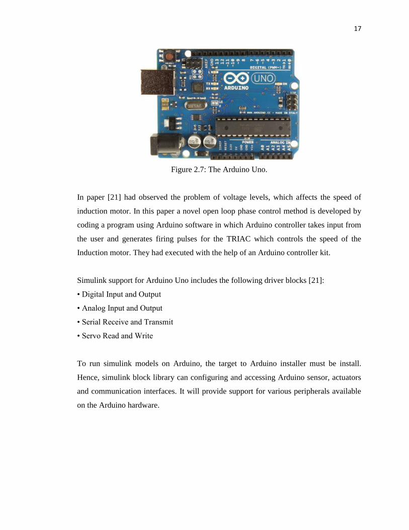
Figure 2.7: The Arduino Uno.
In paper [21] had observed the problem of voltage levels, which affects the speed of
induction motor. In this paper a novel open loop phase control method is developed by
coding a program using Arduino software in which Arduino controller takes input from
the user and generates firing pulses for the TRIAC which controls the speed of the
Induction motor. They had executed with the help of an Arduino controller kit.
Simulink support for Arduino Uno includes the following driver blocks [21]:
• Digital Input and Output
• Analog Input and Output
• Serial Receive and Transmit
• Servo Read and Write
To run simulink models on Arduino, the target to Arduino installer must be install.
Hence, simulink block library can configuring and accessing Arduino sensor, actuators
and communication interfaces. It will provide support for various peripherals available
on the Arduino hardware.

18
In Arduino, the list of port that can be use in order to build controller, are as below [21]:
Block Purpose Description
Analog input
Pin 0 to 5
Measure voltage of
analog input pin
Measure the voltage of an analog pin
relative to the analog input reference
voltage on the Arduino® hardware. Output
the measurement as a 10-bit value that
ranges from 0 to 1023.
Pwm
Pin 3, 5, 6, 9, 10 and 11.
Generate PWM
waveform on analog
output pin
Use pulse-width modulation (PWM) to
change the duty-cycle of square-wave
pulses output by a PWM pin on the
Arduino® hardware.
PWM enables a digital output to provide a
range of different power levels, similar to
that of an analog output. The range of valid
outputs is 0 to 255.
Serial receive and
transmit
Port 0
Get one byte of data
from serial port and
Send buffered data to
serial port.
Serial receive: Get one byte of data per
sample period from the receive buffer of
the specified serial port.
Serial transmit: Send buffered data to the
specified serial port.
Table 2.2: The Arduino pin assignment.
2.5 ANALOG TO DIGITAL AND DIGITAL TO ANALOG CONVERTER
Electronic equipment is frequently used in different fields such as communication,
transportation, entertainment, etc. Analog to Digital Converter (ADC) and Digital to
Analog Converter (DAC) are very important components in electronic equipment. Since
most real world signals are analog, these two converting interfaces are necessary to
allow digital electronic equipments to process the analog signals.

19
Figure 2.8: The ADC and DAC function.
Figure 2.8 above illustrate how the converter is functioning. An Analog to Digital
Converter (ADC) is a device for converting an analog signal such as current or voltage
to a digital binary code. In the real world, most of the signals sensed and processed by
humans are analog signals. ADC is the primary means by which analog signal are
converted into digital data that can be processed by computers for various purposes.
DAC is an inverse function of ADC. In order to get back the signal that can be
processed or sensed by humans or equipment.
In paper [22], a new method of cyclic analog-to-digital (A/D) and digital-to-analog
(D/A) conversion using switched-capacitor techniques is described. By periodically
modifying the reference voltage to compensate for the non ideal signal transfer loop
gain, it is possible in principle to build A/D and D/A converters whose linearity is
independent of component ratios and that occupy only a small die area. These
converters require two moderate-gain MOS operational amplifiers, one comparator, and
a few capacitors. Then they had built and evaluated a test chip for A/D conversion.
Lastly they had tested the data and observed that the A/D performs as a monotonic 13-
bit converter with maximum 1-LSB differential and 2-LSB integral nonlinearity.
20
CHAPTER 3
METHODOLOGY
3.1 BLOCK DIAGRAM OF THE PROJECT
INDUCTION
MOTOR
THREE
PHASE
INVERTER
DC
SOURCE
Hysteresis
controller
GATE
DRIVER
Hysteresis
controller
Hysteresis
controller
Vbc
Vac
Vab
Vref1
Phase shift
0 deg.
Phase shift
120 deg.
Phase shift
240 deg.
6 pulse PWMVoltage
sensor
Vref2
Vref3
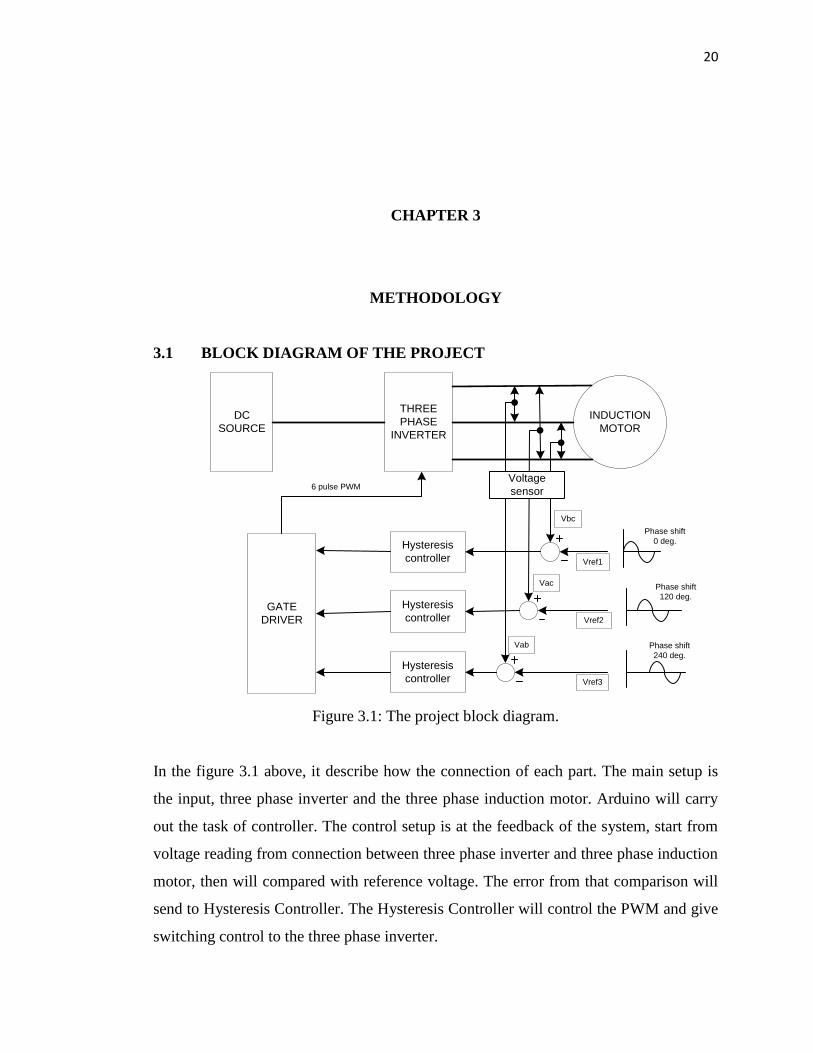
Figure 3.1: The project block diagram.
In the figure 3.1 above, it describe how the connection of each part. The main setup is
the input, three phase inverter and the three phase induction motor. Arduino will carry
out the task of controller. The control setup is at the feedback of the system, start from
voltage reading from connection between three phase inverter and three phase induction
motor, then will compared with reference voltage. The error from that comparison will
send to Hysteresis Controller. The Hysteresis Controller will control the PWM and give
switching control to the three phase inverter.

21
3.2 THE PROJECT FLOWCHART
Figure 3.2: Project flowchart.
Yes
No
START
Hardware part
Study the 3 phase inverter
Study the 3 phase IM
Hysteresis Controller design
Study the structure of
Hysteresis Controller
Software part (MATLAB
simulink)
Hardware setup
Achieve
Yes
No
END
Combination of hardware and software part
Targeted to Arduino
Computer simulation
Observe and analyze
Write thesis and report
Follow
ref

22
The flowchart in figure 3.2 shows the frame work to achieve the project objectives. For
early stage, the task will divide into two parts, which is hardware and software. For
hardware part, MATLAB simulink is the major part that must be cover. It starts from
modeling based on equation, and then simulate to get the observation. Hardware part is
the task to setup the prototype. Both of them will carry out simultaneously so that the
information and progress we get is parallel. Lastly, the hardware and software part will
be combine, and analysis can be done.
3.3 PROJECT DESIGN
To achieve the project hardware, some of designs have been made. In hardware
development, inverter and their gate driver are the first to be design. Then the software
part is the controller design.
3.3.1 THREE PHASE INVERTER DESIGN
The basic three phase inverter topology has 3 leg power switches. Each leg consist of
two power switches. In this project, MOSFET SPP11N60C3 are used. Figure 3.3 shows
the arrangement of three phase inverter in PROTEUS software. Each gate of the
MOSFET needs to give a signal to switching. That‟s why 6 PWM must be built to give
signal to the gate of MOSFET.
Figure 3.3: The three phase inverter in PROTEUS.

23
Figure 3.4: The hardware of three phase inverter.
Figure 3.4 above shows the hardware‟s picture of the three phase inverter. The 2 port at
the left hand side below the capacitor is the Vdc input, the six positive and negative (red
and black wire) is the PWM switching signal and the three ports at right hand side is the
output phase A, B and C in Vac that will fed to induction motor.

24
3.3.2 GATE DRIVER DESIGN
Figure 3.5: The gate driver in PROTEUS software.
Figure 3.5 shows the gate driver for three phase inverter. The function of the gate driver
is to produce 6 pulse PWM signal from three different phase inputs from Arduino. The
gate driver also will power up the voltage from 5V to 15V by voltage regulator IL0515S
before sending it to the three phase inverter. The other main component in the gate
driver is Hex Schmitt trigger Inverters SN7414, HCF4081 and Gate Drive Optocoupler
HCP3120. The picture of the gate driver hardware is shown in figure 3.6.

52
REFERENCES
[1] D. T. H. Tham, D. H. Nghia, “ sliding mode control of induction
motor,”International Symposiumon Electrical Engineering, Oct 25, 2007, 42-47.
[2] Chang Ming Liaw and Wang J. B., “Design and implementation of a fuzzy
controller for a high performance induction motor drive,” IEEE, Vol. 21, No. 4,
August 1991, 921-929.
[3] Kubota K. and Matsuse K., “Speed sensorless field-oriented control of induction
motor with rotor resistance adaptation,” IEEE, Vol. 30, No. 5, October 1994,
1219-1224.
[4] C. Y. Chen, “Sliding mode control design of induction motor based on space
vector PWM method,” ICIC International, Vol. 5, No. 10(B), Oct 2009, 3603-
3614.
[5] Arne Jensen, “Three Phase Inverter,” United States Patent, No. 3573602, April
1971.
[6] Luigi Malesani and Paolo Tenti, “A Novel Hysteresis Control Method for
Current-Controlled Voltage-Source PWM Inverters with Constant Modulation
Frequency,” IEEE, Vol. 26, No. 1, Feb 1990, 88 – 92.
[7] Ojo O. and Davidson I. E., “PWM-VSI inverter-assisted stand-alone dual stator
winding induction generator,” IEEE, Vol. 36, No. 6, November 2000, 1604-
1611.
[8] Doug Deng and Xingyi Xu, “Induction motor controller,” United States patent,
Patent no. 5739664, April 1998.
[9] Lorenz R. D., Lipo T. A. and Novotny D. W., “Motion control with induction
motors,” IEEE, Vol. 82, No. 8, August 1994, 1215-1240.
[10] A. C. Smith and D. G. Dorrel, “Calculation and measurement of unbalanced
magnetic pull in cage induction motors with eccentric rotors. Part 1: Analytical
model,” IEE, Vol. 143, No. 3, May 1996, 193-201.
[11] F. M. Hughes and A. S. Aldred, “Transient characteristics and simulation of
induction motors,” Proceedings of Institution of Electrical Engineers, Vol. 111,
No. 12, December 1964, 2041-2050.

53
[12] Henry James, “Three phase induction motor-operating principle,” Electrical
Engineering Portal, Feb 3, 2013.
[13] S. H. Kim and S. K. sul, “Voltage control strategy for maximum torque
operation of an induction machine in the field-weakening region,” IEEE, Vol.
44, No 4, August 1997, 512-518.
[14] M. Abid, Y. Ramdani and A. K. Meroufel, “Speed sliding mode control of
sensorless induction machine,” Journal of Electrical Engineering, Vol. 57, no. 1,
2006, 47-51.
[15] O. Barambones, P. Alkorta, A. J. Garrido, I. Garrido, F. J. Maseda, “ An
adaptive sliding mode control scheme for induction motor drives,” CSSP
International Journal, Vol. 1, Isssue 1, 2007, 73-78.
[16] Qunying Yao and D. G. Holmes, “A simple, novel method for variable
hysteresis band current control of a three phase inverterwith constant switching
frequency,” IEEE, Vol. 2, October 1993, 1122-1129.
[17] L. M. Fridman, E. I. Shustin and E. M. Fridman, “Steady modes in the relay
control systems with time delay and periodic disturbances,” IEEE, 1997, 75 –
78.
[18] Bertotti, Giorgio (1998). “Hysteresis in magnetism: For physicists, materials
scientists, and engineers,” Academic Press. ISBN 978-0-12-093270-2.
[19] Murat kale, Engin Ozdemir ,”An Adaptive Hysteresis Band Current Controller
for Shunt Active Power Filter”, Electrical Power and Energy Systems, 73 (2005
), 113-119.
[20] Bimal K. Bose, “An Adaptive Hysteresis-Band Current Control Technique of a
Voltage-Fed PWM Inverter for Machine Drive System,” IEEE, Vol. 37, No. 5
October 1990, 402-408.
[21] Y. V. N. Kumar, P. H. Bindu, A. D. Sneha and A. Sravani, “A novel
implementation of phase control technique for speed control of induction motor
using Arduino,” IJETAE, Vol. 3, Issue 4, Apr 2013, 469-472.
[22] C. C. Shih and Paul E. Gray, “Reference refreshing cyclic analog-to-digital and
digital-to-analog converters,” Vol. SC-21, No. 4, August 1986, 544-554.

54
[23] Vadim Utkin, “ Sliding mode control,” Control System, Robotics and
Automation, Vol. 13.


