HyperTransport System Architecture - Mindshare
149
Transcript of HyperTransport System Architecture - Mindshare

training that fi ts your needsMindShare recognizes and addresses your company’s technical training issues with:
• Scalable cost training • Customizable training options • Reducing time away from work• Just-in-time training • Overview and advanced topic courses • Training delivered effectively globally• Training in a classroom, at your cubicle or home offi ce • Concurrently delivered multiple-site training
bringing lifeto knowledge. real-world tech training put into practice worldwide real-world tech training put into practice worldwide real-world tech training put into practice worldwide real-world tech training put into practice worldwide
Are your company’s technical training needs being addressed in the most effective manner?
MindShare has over 25 years experience in conducting technical training on cutting-edge technologies. We understand the challenges companies have when searching for quality, effective training which reduces the students’ time away from work and provides cost-effective alternatives. MindShare offers many fl exible solutions to meet those needs. Our courses are taught by highly-skilled, enthusiastic, knowledgeable and experienced instructors. We bring life to knowledge through a wide variety of learning methods and delivery options.
2 PCI Express 2.0 ®
2 Intel Core 2 Processor Architecture
2 AMD Opteron Processor Architecture
2 Intel 64 and IA-32 Software Architecture
2 Intel PC and Chipset Architecture
2 PC Virtualization
2 USB 2.0
2 Wireless USB
2 Serial ATA (SATA)
2 Serial Attached SCSI (SAS)
2 DDR2/DDR3 DRAM Technology
2 PC BIOS Firmware
2 High-Speed Design
2 Windows Internals and Drivers
2 Linux Fundamentals
... and many more.
All courses can be customized to meet your group’s needs. Detailed course outlines can be found at www.mindshare.com
world-class technical training
MindShare training courses expand your technical skillset
*PCI Express ® is a registered trademark of the PCISIG*PCI Express ® is a registered trademark of the PCISIG

www.mindshare.com 4285 SLASH PINE DRIVE COLORADO SPRINGS, CO 80908 USA M 1.602.617.1123 O 1.800.633.1440 [email protected]
Engage MindShareHave knowledge that you want to bring to life? MindShare will work with you to “Bring Your Knowledge to Life.” Engage us to transform your knowledge and design courses that can be delivered in classroom or virtual class-room settings, create online eLearning modules, or publish a book that you author.
We are proud to be the preferred training provider at an extensive list of clients that include:ADAPTEC • AMD • AGILENT TECHNOLOGIES • APPLE • BROADCOM • CADENCE • CRAY • CISCO • DELL • FREESCALE
GENERAL DYNAMICS • HP • IBM • KODAK • LSI LOGIC • MOTOROLA • MICROSOFT • NASA • NATIONAL SEMICONDUCTOR
NETAPP • NOKIA • NVIDIA • PLX TECHNOLOGY • QLOGIC • SIEMENS • SUN MICROSYSTEMS SYNOPSYS • TI • UNISYS
Classroom Training
Invite MindShare to train you in-house, or sign-up to attend one of our many public classes held throughout the year and around the world. No more boring classes, the ‘MindShare Experience‘ issure to keep you engaged.
Virtual Classroom Training
The majority of our courses live over the web in an inter-active environment with WebEx and a phone bridge. We deliver training cost-effectively across multiple sites and time zones. Imagine being trained in your cubicle or home offi ce and avoiding the hassle of travel. Contact us to attend one of our public virtual classes.
eLearning Module Training
MindShare is also an eLearning company. Our growing list of interactive eLearning modules include:
• Intro to Virtualization Technology
• Intro to IO Virtualization
• Intro to PCI Express 2.0 Updates
• PCI Express 2.0
• USB 2.0
• AMD Opteron Processor Architecture
• Virtualization Technology ...and more
MindShare Press
Purchase our books and eBooks or publish your own content through us. MindShare has authored over 25 books and the listis growing. Let us help make your book project a successful one.
MindShare Learning Options
MindShare Classroom
MindShare Virtual Classroom
MindShare eLearning
MindShare Press
In-House Training
Public Training
Virtual In-House Training
Virtual Public Training
Intro eLearning Modules
Comprehensive eLearning Modules
Books
eBooks
HyperTransport™
System Architecture
MINDSHARE, INC. Don Anderson
Jay Trodden
Boston • San Francisco • New York • Toronto • MontrealLondon • Munich • Paris • Madrid
Capetown • Sydney • Tokyo • Singapore • Mexico City

Many of the designations used by manufacturers and sellers to distinguish their products are claimed as trademarks. Where those designators appear in this book, and Addison-Wesley was aware of the trademark claim, the designa-tions have been printed in initial capital letters or all capital letters.
The authors and publisher have taken care in preparation of this book, but make no expressed or implied warranty of any kind and assume no responsibility for errors or omissions. No liability is assumed for incidental or consequential damages in connection with or arising out of the use of the information or programs contained herein.
The publisher offers discounts on this book when ordered in quantity for bulk purchases and special sales. For more information, please contact:
U.S. Corporate and Government Sales(800) [email protected]
For sales outside of the U.S., please contact:
International Sales(317) [email protected]
Visit Addison-Wesley on the Web: www.awprofessional.com
Library of Congress Cataloging-in-Publication Data
Trodden, Jay. HyperTransport system architecture / Mindshare, Inc., Jay Trodden & Don Anderson. p. cm. Includes index. ISBN 0-321-16845-3 (alk. paper) 1. Data transmission systems. 2. Integrated circuits. 3. Computer architecture. I. Anderson, Don, 1953– II. Mindshare, Inc. III. Title.
TK5105.T745 A53 2003004.6—dc21 2002043927
Copyright © 2003 by MindShare, Inc.
All rights reserved. No part of this publication may be reproduced, stored in a retrieval system, or transmitted, in any form, or by any means, electronic, mechanical, photocopying, recording, or otherwise, without the prior consent of the publisher. Printed in the United States of America. Published simultaneously in Canada.
For information on obtaining permission for use of material from this work, please submit a written request to:
Pearson Education, Inc.Rights and Contracts Department75 Arlington Street, Suite 300Boston, MA 02116Fax: (617) 848-7047
Set in 10 point Palatino by MindShare, Inc.
ISBN: 0-321-16845-31 2 3 4 5 6 7 8 9 10—MA—0706050403First printing, February 2003
Contents
vii
The MindShare Architecture Series ....................................................................................... 1Cautionary Note ......................................................................................................................... 2Intended Audience .................................................................................................................... 2Prerequisite Knowledge ........................................................................................................... 3Topics and Organization .......................................................................................................... 3Documentation Conventions................................................................................................... 4
HyperTransport™................................................................................................................ 4Hexadecimal Notation ........................................................................................................ 4Binary Notation .................................................................................................................... 4Decimal Notation ................................................................................................................. 4Byte Terminology and Notation ........................................................................................ 5Bits Versus Bytes Notation ................................................................................................. 5Bit Fields and Groups of Signals........................................................................................ 5Active Signal States.............................................................................................................. 5
Visit Our Web Site ..................................................................................................................... 6We Want Your Feedback........................................................................................................... 6
Part One: Overview of HyperTransport
Chapter 1: Introduction to HyperTransportBackground: I/O Subsystem Bottlenecks .............................................................................. 9
Server Or Desktop Computer: Three Subsystems ........................................................ 10CPU Speed Makes Other Subsystems Appear Slow .................................................... 10
Multiple CPUs Aggravate The Problem.................................................................. 10DRAM Memory Keeps Up Fairly Well........................................................................... 10I/O Bandwidth Has Not Kept Pace ................................................................................ 11
This Slows Down The Processor .............................................................................. 11It Also Hurts Fast Peripherals................................................................................... 11
Reducing I/O Bottlenecks ................................................................................................ 11The Shared Bus Approach......................................................................................... 11
A Shared Bus Runs At Limited Clock Speeds................................................. 13A Shared Bus May Be Host To Many Device Types ...................................... 13Backward Compatibility Prevents Upgrading Performance ........................ 13Special Problems If The Shared Bus Is PCI ...................................................... 13A Note About PCI-X ........................................................................................... 14
The Point-to-Point Interconnect Approach............................................................. 14A Note About Connectors .................................................................................. 14
What HT Brings........................................................................................................................ 15Key Features Of HyperTransport Protocol .................................................................... 16The Cost Factor................................................................................................................... 16Networking Support.......................................................................................................... 17
Contents
viii
Chapter 2: HT Architectural OverviewTransfer Types Supported...................................................................................................... 21
Address-Based Semantics ................................................................................................. 22Data Transfer Type and Transaction Flow..................................................................... 23
Programmed I/O Transfers ...................................................................................... 24DMA Transfers............................................................................................................ 25Peer-to-Peer Transfers................................................................................................ 26
HT Signals ................................................................................................................................. 27Link Packet Transfer Signals ............................................................................................ 28Link Support Signals ......................................................................................................... 29
Scalable Performance .............................................................................................................. 30Data Widths ........................................................................................................................ 31Clock Speeds....................................................................................................................... 32
Extending the Topology.......................................................................................................... 33Packetized Transfers................................................................................................................ 35
Control Packets................................................................................................................... 36Information packet (4 bytes) ..................................................................................... 36Request packet (4 or 8 bytes)..................................................................................... 36Response packet (4 bytes).......................................................................................... 36
Data Packets........................................................................................................................ 37HyperTransport Protocol Concepts ...................................................................................... 37
Channels and Streams....................................................................................................... 37Virtual Channels ......................................................................................................... 37I/O Streams ................................................................................................................. 39
Transactions (Requests, Responses, and Data).............................................................. 39Transaction Requests.................................................................................................. 40Transaction Responses ............................................................................................... 40
Transaction Types .............................................................................................................. 41Sized Read Transactions ............................................................................................ 41Sized Write Transactions ........................................................................................... 42
Non-Posted Sized Writes.................................................................................... 42Posted Sized Writes............................................................................................. 43
Flush ............................................................................................................................. 44Fence ............................................................................................................................. 45Atomic .......................................................................................................................... 46Broadcast...................................................................................................................... 46
Managing the Links................................................................................................................. 47Flow Control ....................................................................................................................... 47Initialization and Reset...................................................................................................... 49Configuration ..................................................................................................................... 50Error Detection and Handling ......................................................................................... 50
Contents
ix
Part Two: HyperTransport Core Topics
Chapter 3: Signal GroupsIntroduction............................................................................................................................... 53The Signal Groups ................................................................................................................... 54The High Speed Signals (One Set In Each Direction) ...................................................... 55
The CAD Signal Group ..................................................................................................... 55Control Signal (CTL).......................................................................................................... 55Clock Signal(s) (CLK) ........................................................................................................ 55
Scaling Hazards: Burden Is On The Transmitter............................................................... 56The Low Speed Signals........................................................................................................... 56
Power OK (PWROK) And Reset (RESET#) .................................................................... 56LDTSTOP# .......................................................................................................................... 57LDTREQ# ............................................................................................................................ 57
Where Are The Interrupt, Error, And Wait State Signals?............................................... 57Interrupt Signaling............................................................................................................. 58Error Signaling ................................................................................................................... 58Wait State Signaling........................................................................................................... 58
No Arbitration Signals Either................................................................................................ 58
Chapter 4: Packet ProtocolThe Packet-Based Protocol ..................................................................................................... 60
8 Bit Interfaces .................................................................................................................... 60Interfaces Narrower Than 8 Bits ...................................................................................... 62Interfaces Wider Than 8 Bits ............................................................................................ 63
16 Bit Interfaces ........................................................................................................... 6332 Bit Interfaces ........................................................................................................... 64
The Two Packet Types: Control And Data.......................................................................... 65Control Packet Purpose..................................................................................................... 65
Information packets.................................................................................................... 65Request packets........................................................................................................... 65Response packets ........................................................................................................ 66
Data Packets........................................................................................................................ 66The Need To Interleave Control And Data Packets .......................................................... 67
The CTL Signal Indicates Packet Type ........................................................................... 67Packet Format: Control Packets ............................................................................................. 69
Control Packets: Information ........................................................................................... 71NOP Packet.................................................................................................................. 71Sync/Error Packet ...................................................................................................... 74
Control Packets: Requests................................................................................................. 75
Contents
x
Sized Read And Sized Write Requests .................................................................... 75Generic RdSized And WrSized Request Packet Format ................................ 76
RdSized And WrSized Requests: Transaction Limits ........................................... 78RdSized And WrSized (Dword) Transactions ................................................ 79RdSized (Byte) Transactions .............................................................................. 79WrSized (Byte) Transactions.............................................................................. 79
RdSized And WrSized Requests: Other Notes ....................................................... 80Coherency ............................................................................................................. 80WrSized Requests And The Posted Bit............................................................. 80Errors During RdSized Transactions ................................................................ 81PassPW and Response May Pass Posted Requests bits ................................. 81Compatibility Bit.................................................................................................. 82
Broadcast Message Requests..................................................................................... 82Flush Requests............................................................................................................. 84Flush Requests: Transaction Limits ......................................................................... 86Fence Requests ............................................................................................................ 87Fence Requests: Transaction Limits ......................................................................... 88Atomic Read-Modify-Write Requests...................................................................... 89Two Problems In Shared Memory Schemes ........................................................... 89
Atomic RMW Variants........................................................................................ 90Compare And Swap............................................................................................ 90Fetch And Add..................................................................................................... 90
Atomic RMW Requests: Transaction Limits........................................................... 93Control Packets: Responses .............................................................................................. 94
Read Responses........................................................................................................... 94Target Done Responses.............................................................................................. 97
Chapter 5: Flow ControlThe Problem .............................................................................................................................. 99
How PCI Handles Flow Control.................................................................................... 101PCI Target Flow Control Problems ........................................................................ 101
PCI Target Not Ready To Start ........................................................................ 101PCI Target Starts Data Transfer, But Can’t Continue................................... 101PCI Target Starts, Can Continue, But Needs More Time ............................ 102
PCI Initiator Flow Control Problems ..................................................................... 102PCI Initiator Starts, But Can’t Continue......................................................... 102PCI Initiator Starts, Can Continue, But Needs Wait-States ......................... 102
All PCI Flow Control Problems Hurt Performance .................................................... 103
Contents
xi
HyperTransport Flow Control: Overview ......................................................................... 103Packets Never Start Unless Completion Assured ....................................................... 103Transfer Length Is Always Known ............................................................................... 103Split Transactions Used When Response Is Required................................................ 104Flow Control Pins Are Eliminated ................................................................................ 104Flow Control Buffers Mean No Bus Wait States ......................................................... 104Flow Control Buffers For Each Virtual Channel ......................................................... 105
Flow Control, A System View ............................................................................................ 105Flow Control Buffer Arrangement...................................................................................... 106
Details Associated With Figure 5-3 ............................................................................... 107Flow Control Buffer Pairs (Item 1) ......................................................................... 108
Posted Request Buffer (Command). ............................................................... 108Posted Request Buffer (Data). .......................................................................... 108Non-Posted Request Buffer (Command). ...................................................... 108Non-Posted Request Buffer (Data).................................................................. 108Response Buffer (Command)........................................................................... 108Response Buffer (Data). .................................................................................... 108
Receiver Flow Control Counters (Item 2).............................................................. 108Transmitter Flow Control Counters (Item 3) ........................................................ 109NOP Packet Update Information (Item 4)............................................................. 109Control Logic (Item 5) .............................................................................................. 109Transmit And Receive FIFO (Item 6) ..................................................................... 110
Example: Initialization And Use Of The Counters ......................................................... 110Basic Steps In Counter Initialization And Use............................................................. 110
Initializing The Flow Control Counter .................................................................. 111Device 1 Sends Two Posted Request Packets ....................................................... 112New Entries Available: Update Flow Control Information ............................... 114
A Few Implementation Notes.............................................................................................. 115Information Packets Not Flow-Controlled................................................................... 115Transmitter Must Be Able To Track 15 Buffer Entries................................................ 115Sometimes Two Counters Must Be Checked............................................................... 116NOP Packets Cannot Be Completely Blocked ............................................................. 116The Isochronous Flow Control Option ......................................................................... 116
How About NOP Updates For Isochronous Buffers? ......................................... 116Isochronous Traffic/Non-Isochronous Flow Control ......................................... 117Isochronous Traffic Disabled At Initialization ..................................................... 117
Contents
xii
Chapter 6: I/O OrderingThe Purpose Of Ordering Rules ......................................................................................... 120
Maintain Data Coherency............................................................................................... 120Avoid Deadlocks.............................................................................................................. 120Support Legacy buses...................................................................................................... 120Maximize Performance ................................................................................................... 120
Introduction: Three Types Of Traffic Flow ...................................................................... 121The Ordering Rules ............................................................................................................... 122
General I/O Ordering Limits ......................................................................................... 122Ordering Covers Targets At Same Hierarchy Level............................................ 122Read And Non-Posted Write Completion At Target .......................................... 123
What If A Device Requires Response Ordering? .......................................... 124Support For The Producer-Consumer Ordering Model ..................................... 124Producer-Consumer Model Simpler If Flag/Data In Same Place ..................... 124
Upstream Ordering Rules............................................................................................... 125Reordering Packets In Different Transaction Streams ........................................ 125No Reordering Packets In A Strongly Ordered Sequence .................................. 126Packets With PassPW Bit Clear Are Restricted In Passing................................. 127Packets With PassPW Bit Set May Or May Not Pass .......................................... 128Non-Posted Requests May Pass Each Other......................................................... 129Posted Requests And Responses Must Be Able To Pass..................................... 130Posted Request Must Be Able To Pass A Response............................................. 131Non-Posted Requests Or Response May Pass A Response ................................ 132
Host Ordering Requirements ......................................................................................... 132Host Ordering Requirements: General Features.................................................. 133Two Ordering Points Are Defined ......................................................................... 134
Globally Ordered (GO) ..................................................................................... 134Globally Visible (GV) ........................................................................................ 134
Ordering Rule Summary ......................................................................................... 134Host Responses To Non-Posted Requests............................................................. 135An Example (Refer to Table 6-1 and Figure 6-13) ................................................ 136Downstream I/O Ordering ..................................................................................... 136Double-Hosted Chain Ordering ............................................................................. 137
Chapter 7: Transaction ExamplesPackets As Transaction Building Blocks ........................................................................... 140Transaction Examples: Introduction .................................................................................. 144
Packet Format And Optional Features ......................................................................... 144General Sequence Of Events .......................................................................................... 144
Contents
xiii
Example 1: NOP Information Packet.................................................................................. 145Example 1: NOP Packet Setup ....................................................................................... 146
Command[5:0] Field (Byte 0, Bit 5:0) ..................................................................... 146DisCon Bit Field (Byte 0, Bit 6)................................................................................ 146PostCMD[1:0] Field (Byte 1, Bits 1:0) ..................................................................... 146PostData[1:0] Field (Byte 1, Bits 3:2)....................................................................... 146Response[1:0] Field (Byte 1, Bits 5:4)...................................................................... 146ResponseData[1:0] Field (Byte 1, Bits 3:2) ............................................................. 147Non-PostCMD[1:0] Field (Byte 2, Bits 1:0) ............................................................ 147Non-PostData[1:0] Field (Byte 2, Bits 3:2) ............................................................. 147Isoc Bit Field (Byte 2, Bit 5) ...................................................................................... 147Diag Bit Field (Byte 2, Bit 6)..................................................................................... 147Bits Not Mentioned .................................................................................................. 147
Example 1: NOP Sequence Of Events On The Link.................................................... 148Generic Request And Response Packet Formats ............................................................. 148Example 2: Non-Posted WrSized (Dword) Transaction ................................................. 150
Example 2: WrSized (Dword) Request Packet Setup.................................................. 151Command[5:0] Field (Byte 0, Bit 5:0) ..................................................................... 151SeqID[3:0] Field (Byte 0, Bit 7:6) and (Byte 1, Bit 6:5) .......................................... 151UnitID[4:0] Field (Byte 1, Bits 4:0) .......................................................................... 151PassPW Bit Field (Byte 1, Bit 7)............................................................................... 151SrcTag[4:0] Field (Byte 2, Bits 4:0) .......................................................................... 151Compat Bit Field (Byte 2, Bit 5)............................................................................... 152Mask/Count[3:0] Field (Byte 2, Bits 7:6) & (Byte 3, Bits 1:0) .............................. 152Start Address Field (Bytes 4-7, Bit 7:0) & (Byte 3, Bit 7:2) ................................... 152
Example 2: WrSized (Dword) Transaction Data ......................................................... 152Example 2: WrSized (Dword) Request Sequence Of Events ..................................... 153Example 2: The WrSized (Dword) Response Packet .................................................. 154
Command[5:0] Field (Byte 0, Bit 5:0) ..................................................................... 154Isoc Bit Field (Byte 0, Bit 7) ...................................................................................... 154UnitID[4:0] Field (Byte 1, Bits 4:0) .......................................................................... 154Bridge Bit Field (Byte 1, Bit 6) ................................................................................. 155PassPW Bit Field (Byte 1, Bit 7)............................................................................... 155SrcTag[4:0] Field (Byte 2, Bits 4:0) .......................................................................... 155Error Bit Field (Byte 2, Bit 5).................................................................................... 155NXA Bit Field (Byte 3, Bit 5).................................................................................... 155
Example 2: WrSized (Dword) Response, Sequence Of Events.................................. 156Example 3: Posted Byte Write Request .............................................................................. 156
Example 3: WrSized (Byte) Request Packet Setup ...................................................... 156Command[5:0] Field (Byte 0, Bit 5:0) ..................................................................... 156SeqID[3:0] Field (Byte 0, Bit 7:6) and (Byte 1, Bit 6:5) .......................................... 158UnitID[4:0] Field (Byte 1, Bits 4:0) .......................................................................... 158

Contents
xiv
PassPW Bit Field (Byte 1, Bit 7)............................................................................... 158SrcTag[4:0] Field (Byte 2, Bits 4:0) .......................................................................... 158Compat Bit Field (Byte 2, Bit 5)............................................................................... 158Mask/Count[3:0] Field (Byte 2, Bits 7:6 and Byte 3, Bits 1:0) ............................. 158Start Address Field (Bytes 4-7, Bit 7:0) and Byte 3, Bit 7:2)................................. 159
Example 3: Sized (Byte) Write Data Packet And Mask .............................................. 159Example 3: WrSized (Byte) Request, Sequence Of Events ......................................... 160A Couple Of Notes About WrSized (Byte)................................................................... 160
Example 4: Dword Read Request........................................................................................ 161Example 4: RdSized (Dword) Request Packet Setup .................................................. 162
Command[5:0] Field (Byte 0, Bit 5:0) ..................................................................... 162SeqID[3:0] Field (Byte 0, Bit 7:6) and (Byte 1, Bit 6:5) .......................................... 162UnitID[4:0] Field (Byte 1, Bits 4:0) .......................................................................... 162PassPW Bit Field (Byte 1, Bit 7)............................................................................... 162SrcTag[4:0] Field (Byte 2, Bits 4:0) .......................................................................... 162Compat Bit Field (Byte 2, Bit 5)............................................................................... 162Mask/Count[3:0] Field (Byte 2, Bits 7:6) and (Byte 3, Bits 1:0) .......................... 163Start Address Field (Bytes 4-7, Bit 7:0) and (Byte 3, Bit 7:2) ............................... 163
Example 4: RdSized (Dword) Request, Sequence Of Events..................................... 163Example 4: Dword Read Response Packet Setup........................................................ 164
Command[5:0] Field (Byte 0, Bit 5:0) ..................................................................... 164Isoc Bit Field (Byte 0, Bit 7) ...................................................................................... 164UnitID[4:0] Field (Byte 1, Bits 4:0) .......................................................................... 164Bridge Bit Field (Byte 1, Bit 6) ................................................................................. 164PassPW Bit Field (Byte 1, Bit 7)............................................................................... 164SrcTag[4:0] Field (Byte 2, Bits 4:0) .......................................................................... 165Error Bit Field (Byte 2, Bit 5).................................................................................... 165Count[3:0] Field (Byte 2, Bits 7:6) and (Byte 3, Bits 1:0)....................................... 165NXA Bit Field (Byte 3, Bit 5).................................................................................... 165
Example 4: Sized (Dword) Read Data Packet .............................................................. 165Example 4: RdSized (Dword) Response, Sequence Of Events .................................. 166
Example 5: Byte Read Request ............................................................................................ 167Example 5: RdSized (Byte) Request Packet Setup....................................................... 168
Command[5:0] Field (Byte 0, Bit 5:0) ..................................................................... 168SeqID[3:0] Field (Byte 0, Bit 7:6) and (Byte 1, Bit 6:5) .......................................... 168UnitID[4:0] Field (Byte 1, Bits 4:0) .......................................................................... 168PassPW Bit Field (Byte 1, Bit 7)............................................................................... 168SrcTag[4:0] Field (Byte 2, Bits 4:0) .......................................................................... 168Compat Bit Field (Byte 2, Bit 5)............................................................................... 168Mask/Count[3:0] Field (Byte 2, Bits 7:6) and (Byte 3, Bits 1:0) .......................... 169Start Address Field (Bytes 4-7, Bit 7:0) and Byte 3, Bit 7:2)................................. 169
Example 5: RdSized (Byte) Request, Sequence Of Events ......................................... 169

Contents
xv
Example 5: Byte Read Response Packet Setup ............................................................ 170Command[5:0] Field (Byte 0, Bit 5:0) ..................................................................... 170Isoc Bit Field (Byte 0, Bit 7) ...................................................................................... 170UnitID[4:0] Field (Byte 1, Bits 4:0) .......................................................................... 170Bridge Bit Field (Byte 1, Bit 6) ................................................................................. 170PassPW Bit Field (Byte 1, Bit 7)............................................................................... 171SrcTag[4:0] Field (Byte 2, Bits 4:0) .......................................................................... 171Error Bit Field (Byte 2, Bit 5).................................................................................... 171Count[3:0] Field (Byte 2, Bits 7:6) and (Byte 3, Bits 1:0)....................................... 171NXA Bit Field (Byte 3, Bit 5).................................................................................... 171
Example 5: Sized (Byte) Read Data Packet................................................................... 172Example 5: RdSized (Byte) Response, Sequence Of Events....................................... 172
SrcTag[4:0] Field (Byte 2, Bits 4:0) .......................................................................... 173Example 6: Flush Request..................................................................................................... 173
Example 6: Flush Request Packet Setup ....................................................................... 175Command[5:0] Field (Byte 0, Bit 5:0) ..................................................................... 175SeqID[3:0] Field (Byte 0, Bit 7:6) and (Byte 1, Bit 6:5) .......................................... 175UnitID[4:0] Field (Byte 1, Bits 4:0) .......................................................................... 175PassPW Bit Field (Byte 1, Bit 7)............................................................................... 175
Example 6: Flush Request, Sequence Of Events .......................................................... 176Example 6: Flush Response Packet Setup..................................................................... 176
Command[5:0] Field (Byte 0, Bit 5:0) ..................................................................... 176UnitID[4:0] Field (Byte 1, Bits 4:0) .......................................................................... 176Bridge Bit Field (Byte 1, Bit 6) ................................................................................. 177PassPW Bit Field (Byte 1, Bit 7)............................................................................... 177SrcTag[4:0] Field (Byte 2, Bits 4:0) .......................................................................... 177Error Bit Field (Byte 2, Bit 5).................................................................................... 177NXA Bit Field (Byte 3, Bit 5).................................................................................... 177
Example 6: Flush Response, Sequence Of Events ....................................................... 178A Few Notes About Flush Operations.......................................................................... 178
Example 7: Fence Request..................................................................................................... 179Example 7: Fence Request Packet Setup....................................................................... 180
Command[5:0] Field (Byte 0, Bit 5:0) ..................................................................... 180SeqID[3:0] Field (Byte 0, Bit 7:6) and (Byte 1, Bit 6:5) .......................................... 180UnitID[4:0] Field (Byte 1, Bits 4:0) .......................................................................... 180PassPW Bit Field (Byte 1, Bit 7)............................................................................... 180
Example 7: Fence Request, Sequence Of Events.......................................................... 180A Few Notes About Fence Operations ......................................................................... 181
Contents
xvi
Example 8: Atomic Read-Modify-Write............................................................................. 182Example 8: Atomic RMW Request Packet Setup......................................................... 183
Command[5:0] Field (Byte 0, Bit 5:0) ..................................................................... 183SeqID[3:0] Field (Byte 0, Bit 7:6) and (Byte 1, Bit 6:5) .......................................... 183UnitID[4:0] Field (Byte 1, Bits 4:0) .......................................................................... 183PassPW Bit Field (Byte 1, Bit 7)............................................................................... 183SrcTag[4:0] Field (Byte 2, Bits 4:0) .......................................................................... 183Compat Bit Field (Byte 2, Bit 5)............................................................................... 183Mask/Count[3:0] Field (Byte 2, Bits 7:6) and (Byte 3, Bits 1:0) .......................... 184Start Address Field (Bytes 4-7, Bit 7:0) and (Byte 3, Bit 7:2) ............................... 184
Example 8: Atomic RMW Request Data Packet .......................................................... 184Example 8: Atomic RMW Request, Sequence Of Events ........................................... 184Example 8: Atomic RMW Response Packet Setup...................................................... 185
Command[5:0] Field (Byte 0, Bit 5:0) ..................................................................... 185Isoc Bit Field (Byte 0, Bit 7) ...................................................................................... 185UnitID[4:0] Field (Byte 1, Bits 4:0) .......................................................................... 185Bridge Bit Field (Byte 1, Bit 6) ................................................................................. 186PassPW Bit Field (Byte 1, Bit 7)............................................................................... 186SrcTag[4:0] Field (Byte 2, Bits 4:0) .......................................................................... 186Error Bit Field (Byte 2, Bit 5).................................................................................... 186Count[3:0] Field (Byte 2, Bits 7:6) and (Byte 3, Bits 1:0)....................................... 186NXA Bit Field (Byte 3, Bit 5).................................................................................... 186
Example 8: Atomic RMW Response Data Packet........................................................ 187Example 8: Atomic RMW Response, Sequence Of Events......................................... 187Some Notes About Atomic RMW Operations............................................................. 188
Example 9: WrSized Request Crosses A Bridge............................................................... 189Example 9: Request Packet On Bus 1 ............................................................................ 190
Command[5:0] Field (Byte 0, Bit 5:0) ..................................................................... 190SeqID[3:0] Field (Byte 0, Bit 7:6) and (Byte 1, Bit 6:5) .......................................... 190UnitID[4:0] Field (Byte 1, Bits 4:0) .......................................................................... 190PassPW Bit Field (Byte 1, Bit 7)............................................................................... 190SrcTag[4:0] Field (Byte 2, Bits 4:0) .......................................................................... 190Compat Bit Field (Byte 2, Bit 5)............................................................................... 190Mask/Count[3:0] Field (Byte 2, Bits 7:6) & (Byte 3, Bits 1:0) .............................. 191Start Address Field (Bytes 4-7, Bit 7:0) & (Byte 3, Bit 7:2) ................................... 191
Example 9: Sized (Dword) Write Data Packet: Bus 1 ................................................. 191Example 9: Request/Data Sequence Of Events On Bus 1 .......................................... 191Example 9: Bridge Reissues Request Packet: Bus 0..................................................... 192
Command[5:0] Field (Byte 0, Bit 5:0) ..................................................................... 192SeqID[3:0] Field (Byte 0, Bit 7:6) and (Byte 1, Bit 6:5) .......................................... 192UnitID[4:0] Field (Byte 1, Bits 4:0) .......................................................................... 192PassPW Bit Field (Byte 1, Bit 7)............................................................................... 192
Contents
xvii
SrcTag[4:0] Field (Byte 2, Bits 4:0) .......................................................................... 192Compat Bit Field (Byte 2, Bit 5)............................................................................... 193Mask/Count[3:0] Field (Byte 2, Bits 7:6) & (Byte 3, Bits 1:0) .............................. 193Start Address Field (Bytes 4-7, Bit 7:0) & (Byte 3, Bit 7:2) ................................... 193
Example 9: Sized (Dword) Write Data Packet: Bus 0 ................................................. 193Example 9: Request/Data Sequence Of Events: Bus 0 ............................................... 193Example 9: Response Packet On Bus 0 ......................................................................... 194
Command[5:0] Field (Byte 0, Bit 5:0) ..................................................................... 194Isoc Bit Field (Byte 0, Bit 7) ...................................................................................... 194UnitID[4:0] Field (Byte 1, Bits 4:0) .......................................................................... 194Bridge Bit Field (Byte 1, Bit 6) ................................................................................. 194PassPW Bit Field (Byte 1, Bit 7)............................................................................... 194SrcTag[4:0] Field (Byte 2, Bits 4:0) .......................................................................... 194Error Bit Field (Byte 2, Bit 5).................................................................................... 195NXA Bit Field (Byte 3, Bit 5).................................................................................... 195
Example 9: Response, Sequence Of Events On Bus 0 ................................................. 195Example 9: Response Packet On Bus 1 ......................................................................... 195
Command[5:0] Field (Byte 0, Bit 5:0) ..................................................................... 195Isoc Bit Field (Byte 0, Bit 7) ...................................................................................... 196UnitID[4:0] Field (Byte 1, Bits 4:0) .......................................................................... 196Bridge Bit Field (Byte 1, Bit 6) ................................................................................. 196PassPW Bit Field (Byte 1, Bit 7)............................................................................... 196SrcTag[4:0] Field (Byte 2, Bits 4:0) .......................................................................... 196Error Bit Field (Byte 2, Bit 5).................................................................................... 196NXA Bit Field (Byte 3, Bit 5).................................................................................... 196
Example 9: Response, Sequence Of Events On Bus 1 ................................................. 196
Chapter 8: HT InterruptsIntroduction............................................................................................................................. 199Discovering a Device’s Interrupt Requirements ............................................................. 200The Interrupt Message Address Range ............................................................................. 201Interrupt Requests ................................................................................................................. 204
Interrupt Request Packet................................................................................................. 204Interrupt Request Data Packet ....................................................................................... 206The End of Interrupt (EOI) Message ............................................................................. 207
EOI Packet Format.................................................................................................... 208Interrupt Discovery and Configuration Capability Block............................................. 209
Interrupt Capability Block Format ................................................................................ 209Last Interrupt Supported......................................................................................... 211Interrupt Definition Registers ................................................................................. 211
Contents
xviii
Chapter 9: System ManagementSystem Management Transactions ..................................................................................... 216
Sources of SM Request .................................................................................................... 216System Management Address Range ........................................................................... 217The SMC & Upstream Request Packets ........................................................................ 218
Upstream Request Packet Format .......................................................................... 218System Management Commands — Upstream............................................ 219
The Host Bridge & Downstream Request Packets ...................................................... 220Downstream Request Packet Format..................................................................... 220
System Management Commands ................................................................... 221HT Link Disconnect/Reconnect Sequence ........................................................................ 223
Reference Information: LDTSTOP# Procedures.......................................................... 223Example SM Sequence: Link Initialization Disconnect................................................. 225
Background....................................................................................................................... 225Setup and Assumptions .................................................................................................. 225The Link Initialization Disconnect Sequence............................................................... 227
Chapter 10: Error Detection And HandlingIntroduction............................................................................................................................. 230
Types Of Errors ................................................................................................................ 230Reporting Methods .......................................................................................................... 230The Role Of PCI Configuration Space........................................................................... 230Most Types Of Error Checking Are Optional .............................................................. 231System Handling Of HyperTransport Errors Varies .................................................. 231
The Error Types ...................................................................................................................... 231CRC Errors ........................................................................................................................ 231
CRC On 8, 16, or 32 bit Interfaces........................................................................... 232CRC Generation/Checking: 8/16/32 bit links..................................................... 232CRC Generation/Checking: 2/4 bit links ............................................................. 233
4 Bit CAD Width................................................................................................ 2332 Bit CAD Width................................................................................................ 233
Logging CRC Errors ................................................................................................. 233Programming The CRC Error Reporting Policy .................................................. 234
CRC Interrupts................................................................................................... 234CRC Sync Flood ................................................................................................. 235
CRC Test Mode ......................................................................................................... 237Protocol Errors.................................................................................................................. 237
CTL Signal Four-Byte Boundary Violation ........................................................... 237CTL Deassertion Violation ...................................................................................... 238CTL/Data Interleaving Violation........................................................................... 238
Contents
xix
Bad Command Code In Control Packet ................................................................ 238CTL Deassertion Timeout Violation ...................................................................... 238CTL Deasserted During CRC Transmission ......................................................... 238Logging Protocol Errors........................................................................................... 238Programming The Protocol Error Reporting Policy ............................................ 239
Receive Buffer Overflow Errors..................................................................................... 241Logging Receive Buffer Overflow Errors .............................................................. 241Programming The Buffer Overflow Error Reporting Policy.............................. 242
End-Of-Chain Errors ....................................................................................................... 243How A Device Knows It Is At The End Of A Chain ........................................... 243Logging End-Of-Chain Errors ................................................................................ 245Programming The EOC Error Reporting Policy .................................................. 246
Chain Down Errors.......................................................................................................... 247Response Errors................................................................................................................ 248
Response Error Logging And Reporting Policy................................................... 249Error Reporting....................................................................................................................... 250
Error Responses (Non-Posted Requests Only) ............................................................ 250Error Response Returned By The Target............................................................... 251Error Response Returned By An End-Of-Chain Device ..................................... 251
Fatal And Non-Fatal Interrupts ..................................................................................... 252Sync Flood: When All Else Fails .................................................................................... 253
Device Initiating The Sync Flood ........................................................................... 253Devices Detecting Sync Flood................................................................................. 253Sync Flooding And HyperTransport Bridges....................................................... 254Miscellaneous Notes................................................................................................. 254
Flooding Continues Until Reset ...................................................................... 254CRC Not Checked During Sync Flood ........................................................... 254
Sync Flood Example ................................................................................................. 254Sequence of events: (Figure 10-15 on page 255) ................................................... 254
Chapter 11: Routing PacketsPacket Routing: Shared Bus vs. Point-Point Topology................................................... 258
Shared Bus Routing ......................................................................................................... 258HyperTransport Point-Point Routing ........................................................................... 259
Review Of Packet Types And Formats .............................................................................. 259Control Packets................................................................................................................. 259
Information Packets: No Routing Required.......................................................... 259Request Packet Routing Information..................................................................... 260
Six Request Types.............................................................................................. 261Response Packet Routing Information .................................................................. 262
Data Packet Routing Depends On Control Packets .................................................... 263Directed vs. Broadcast Requests ......................................................................................... 263
Contents
xx
Accepting Packets .................................................................................................................. 264Rules For Acceptance ...................................................................................................... 264
A Note About The Subtractive Decoder................................................................ 264Forwarding Packets................................................................................................................ 265
Rules For Forwarding...................................................................................................... 265Other Notes On Forwarding .......................................................................................... 265
Forwarding Into The End Of Chain ....................................................................... 265Forwarding If Initialization Is Not Complete....................................................... 266
Rejecting Packets.................................................................................................................... 266Rules For Rejection .......................................................................................................... 266
Host Bridge Behavior ............................................................................................................ 267Directed Request With UnitID = 0................................................................................. 267
Accepted..................................................................................................................... 267Rejected ...................................................................................................................... 267Response UnitID And Bridge Fields...................................................................... 268
Broadcast Request ............................................................................................................ 268Always Accepted ...................................................................................................... 268
Directed Request With Non-Zero UnitID .................................................................... 268Accepted Requests.................................................................................................... 268
Internal Target.................................................................................................... 268Peer-to-Peer Target............................................................................................ 269
Compatibility Chain Requests ................................................................................ 269Rejected Requests...................................................................................................... 270
Responses Received By The Host Bridge ..................................................................... 270Response With Bridge Bit = 1.................................................................................. 270Response With Bridge Bit = 0.................................................................................. 270
HyperTransport Bridges: Additional Routing Rules...................................................... 271Tunnel Fairness And Forward Progress ............................................................................ 271
Fairness Is Critical In A Point-Point Topology............................................................ 271HyperTransPort Imposes A Fairness Algorithm ........................................................ 272
The Basic Policy......................................................................................................... 272The Algorithm ........................................................................................................... 272
First, Calculate The Insertion Rate .................................................................. 272Insertion Rate Calculation Example ............................................................... 273
Chapter 12: Reset & InitializationGeneral ..................................................................................................................................... 276Cold Reset................................................................................................................................ 276
Sources of Cold Reset ...................................................................................................... 277Resetting the Primary HT Bus ................................................................................ 277Resetting Secondary Side of HT-to-HT Bridge..................................................... 278
Contents
xxi
Signalling and Detecting Cold Reset............................................................................. 280Effects of Cold Reset ........................................................................................................ 281
Link Initialization .................................................................................................................. 282Low-Level Link Width Initialization ............................................................................ 282
Determining Low-Level Link Width ..................................................................... 283Example 1: 4-bit device connected to 8-bit Device ....................................... 284Example 2: 8-Bit Device Connected to 4/8-Bit Device................................. 285Example 3: 32-bit Upstream and 16-bit Downstream .................................. 286
Negotiated Link Width Stored in Link Config Registers.................................... 288Low-Level Clock Initialization....................................................................................... 289
The Default Clock Frequency.................................................................................. 291Control and CAD Sequence after Reset is Removed .................................................. 291
Clock Synchronization (CTL=0 & CAD=0)........................................................... 292Duration of CTL & CAD Driven Low ................................................................... 293Packet Framing and Initializing the CRC Window ............................................. 294
Tuning the Link Width (Firmware Initialization) ....................................................... 295Tuning Example 1: 4-bit device connected to 8-bit Device.......................... 297Tuning Example 2: 8-bit device connected to 4/8-bit Device ..................... 297Tuning Example 3: 32-bit Upstream and 16-bit Downstream .................... 298
Tuning the Clock Frequency .......................................................................................... 299Warm Reset.............................................................................................................................. 302
Warm Reset Generated by Software ...................................................................... 303LDTSTOP# Disconnect Sequence ...................................................................................... 304
Chapter 13: Device ConfigurationHyperTransport Uses PCI Configuration.......................................................................... 306What PCI Configuration Accomplishes ............................................................................ 306HyperTransport System Limits ........................................................................................... 307
256 Buses In A System..................................................................................................... 30732 UnitIDs Per Bus ........................................................................................................... 307One To Eight Functions Per Device............................................................................... 307256 Bytes Of Configuration Space ................................................................................. 308
Configuration Accesses: Reaching All Devices ............................................................... 308Review: How PCI Handles Configuration Accesses....................................................... 309
Two Configuration Cycle Types.................................................................................... 309Type 1 Cycle Until Target Bus Is Reached ................................................................... 309Target Bus Bridge: Convert To Type 0; Assert IDSEL................................................ 310An Example: A PCI Configuration Space Access........................................................ 310
Events In PCI Configuration Space Example (see Figure 13-1) ......................... 311
Contents
xxii
How HyperTransport Handles Configuration Accesses ................................................ 311Configuration Cycles Are Memory Mapped ............................................................... 311How The 32MB Configuration Area Is Used............................................................... 312
Upper 16 Address Bits Indicate Type 0 And Type 1 Cycle ................................ 313HyperTransport Type 1 Configuration Cycle (See Figure 13-3) ........................ 314HyperTransport Type 0 Configuration Cycle (See Figure 13-3) ........................ 314
No IDSEL Signal Needed In HyperTransport ............................................................. 314Example: HT Configuration Space Access ................................................................... 315
Events In HT Configuration Example (see Figure 13-4) ..................................... 316Initializing Bus Numbers And Unit IDs ....................................................................... 316
Case 1: A Single Chain With One Host Bridge..................................................... 316Case 2: A HyperTransport Bridge Is Discovered................................................. 318
A Note About Bus Numbering In HyperTransport ..................................... 318Case 3: Initializing A Double Hosted Chain......................................................... 320
Only One Master Host Bridge ......................................................................... 320Master Bridge Initialization/Configuration Sequence ................................ 320
HyperTransport Configuration Space Format.................................................................. 321Two Header Formats Are Used ..................................................................................... 321The Type 0 Header Format............................................................................................. 322PCI Advanced Capability Registers .............................................................................. 323
Many Advanced Capabilities Are Defined........................................................... 324Discovering The Advanced Capability Blocks ..................................................... 324
HyperTransport Configuration Type 0 Header Fields............................................... 325Header Command Register..................................................................................... 325Header Status Register............................................................................................. 326
Other Fields In The Header ............................................................................................ 329Cache Line Size Register. (Offset 0Ch) .................................................................. 329Latency Timer Register. (Offset 0Dh) .................................................................... 329Base Address Registers. (Offset 10h-24h).............................................................. 329
I/O BAR.............................................................................................................. 329Memory BAR...................................................................................................... 329
CardBus CIS Pointer. (Offset 28h) .......................................................................... 330Capabilities Pointer. (Offset 34h)............................................................................ 330Interrupt Line Register. (Offset 3Ch) ..................................................................... 330Interrupt Pin Register. (Offset 3Dh)....................................................................... 330Min_Gnt and Max_Latency Registers. (Offsets 3Eh and 3Fh) ........................... 330
HyperTransport Uses Advanced Capability Blocks................................................... 330HyperTransport Block Types Currently Defined ................................................ 331Block Formats Vary With Capability And Device Type ..................................... 332
The Slave/Primary Interface Block ............................................................................... 332
Contents
xxiii
Description Of Slave/Primary Interface Fields ........................................................... 333Capability ID Register. (Offset 00h) ....................................................................... 334Capabilities Pointer Register. (Offset 01h) ............................................................ 334Slave Command Register. (Offset 02h-03h) .......................................................... 335Link Control Registers. (Offset 04h and 08h)........................................................ 336Link Configuration Registers. (Offset 06h and 0Ah) ........................................... 339Revision ID Register. (Offset 0Ch) ......................................................................... 343Link Frequency Registers. (Offset 0Dh and 11h) ................................................. 344Link Error Registers. (Offset 0Dh and 11h)........................................................... 345Link Frequency Capability Registers. (Offset 0Eh and 12h)............................... 346Feature Capability Register. (Offset 10h) .............................................................. 347Enumeration Scratch Pad Register. (Offset 14h) .................................................. 349Error Handling Register. (Offset 16h).................................................................... 350Memory Base Upper Register. (Offset 18h) .......................................................... 352Memory Limit Upper Register. (Offset 19h)......................................................... 352
The Host/Secondary Interface Block ............................................................................ 354Description Of Host/Secondary Interface Fields........................................................ 355
Capability ID Register. (Offset 00h) ....................................................................... 355Capabilities Pointer Register. (Offset 01h) ............................................................ 355Host Command Register. (Offset 02h-03h) ........................................................... 356Link Control Register. (Offset 04h) ........................................................................ 358Link Configuration Register. (Offset 06h)............................................................. 358Revision ID. (Offset 08h).......................................................................................... 358Link Frequency And Link Error Registers. (Offset 09h) ..................................... 359Link Frequency Capability. (Offset 0Ah) .............................................................. 359Feature Capability Register. (Offset 0Ch) ............................................................. 359Enumeration Scratchpad Register. (Offset 10h) ................................................... 360Error Handling Register. (Offset 12h).................................................................... 360Memory Base/Limits Upper Registers. (Offset 14h, 15h)................................... 361
Revision ID Capability Block ......................................................................................... 361
Chapter 14: ElectricalBackground and Introduction ............................................................................................. 364Power Requirements ............................................................................................................. 366
Power Supply Voltage..................................................................................................... 366Differential Pair Power Consumption .......................................................................... 366
Differential Signaling Characteristics ............................................................................... 367Differential DC Characteristics ...................................................................................... 367
Differential DC Impedance ..................................................................................... 368Differential Output Voltage - DC ........................................................................... 369Differential Input Voltage - DC .............................................................................. 371
Contents
xxiv
Differential AC Characteristics ...................................................................................... 372Differential AC Impedance ..................................................................................... 372Differential Output Voltage - AC ........................................................................... 374Differential Input Voltage - AC .............................................................................. 376Input Rising and Falling Edge Rates...................................................................... 377
Single-Ended Signaling Characteristics ............................................................................ 378Differential Timing Characteristics ................................................................................... 379
Differential Signal Skew.................................................................................................. 379Source Synchronous Clock Skew................................................................................... 381
Source Synchronous Clock Skew at the Transmitter........................................... 381Source Synchronous Clock Skew at the Receiver ................................................ 383
Setup and Hold Timing................................................................................................... 384Testing...................................................................................................................................... 385
Chapter 15: ClockingIntroduction............................................................................................................................. 388Clock Initialization ................................................................................................................ 388Synchronous Clock Mode .................................................................................................... 389
A Conceptual Example.................................................................................................... 389Sources of Transmit and Receive Clock Variance ....................................................... 390
Invariant Sources ...................................................................................................... 391Cross-byte skew in multi-byte link implementations. ................................. 391Sampling Error................................................................................................... 392
Variant Sources ......................................................................................................... 392Reference Clock Distribution Skew ................................................................ 392PLL Variation in Transmitter and Receiver................................................... 392Transmitter and Link Transfer Variation....................................................... 393Receiver Transfer Variation ............................................................................. 393Dynamic Cross Byte-Lane Variation .............................................................. 393
An Example Timing Budget.................................................................................... 393Clock Variance, FIFO Size, and the Read Pointer ....................................................... 394
Minimum FIFO Size ................................................................................................. 395Write-to-Read and Read-to-Write Separation ...................................................... 395
Scenario 1: Tx Out Clock and Rx Clock are in Sync ..................................... 396Scenario 2: Tx Clock Out Lags Rx Clock ........................................................ 397Scenario 3: Rx Clock Lags Tx Clock Out ........................................................ 398
Buffering Width and Speed Differences ....................................................................... 399CAD/CTL synchronization time: ................................................................... 399
Contents
xxv
Pseudo-Synchronous Clock Mode ................................................................................ 399Why Use Pseudo-Synchronous Clock Mode? ...................................................... 400Implementation Issues ............................................................................................. 401
Methods and Procedures.................................................................................. 401FIFO Management............................................................................................. 401Is Support for Pseudo-Sync Mode Required? ............................................... 402
Asynchronous Clock Mode ............................................................................................ 402Transmit Clock Slower Than Receive Clock......................................................... 402Transmit Clock Faster Than Receive Clock .......................................................... 402
Part Three: HyperTransport Optional Topics
Chapter 16: HyperTransport BridgesHyperTransport Bridges Uses PCI Configuration........................................................... 408Basic Jobs Of A HyperTransport Bridge ........................................................................... 408How Does The Bridge Manage It All? ............................................................................... 409
Same Slave/Primary And Host/Secondary Blocks.................................................... 409HyperTransport Bridge Header Fields ......................................................................... 409
Bridge Header Command Register ........................................................................ 410Bridge Header Status Register ................................................................................ 413Secondary Status Register ....................................................................................... 415Memory And Prefetchable Base And Limit Registers......................................... 416Memory And Prefetchable Memory Base/Limit Notes...................................... 419
Bus-To-Bus Forwarding Rules......................................................................... 41964 Bit Addressing And The 40 Bit HyperTransport Space.......................... 419To Disable Memory or Prefetchable Memory Decoding ............................. 419The Optional Address Remapping Registers ................................................ 419
I/O Base And Limit Registers................................................................................. 420Base/Limit Notes...................................................................................................... 421
Bus-To-Bus Forwarding Rules......................................................................... 421To Disable I/O Decoding ................................................................................. 422
Bridge Control Register ........................................................................................... 422Other Fields In The Header ............................................................................................ 424
Primary Latency Timer Register............................................................................. 424Base Address Registers ............................................................................................ 424
I/O BAR.............................................................................................................. 424Memory BAR...................................................................................................... 424
Capabilities Pointer .................................................................................................. 425Interrupt Line Register............................................................................................. 425Interrupt Pin Register............................................................................................... 425Cache Line Size Register.......................................................................................... 425
Contents
xxvi
Chapter 17: Double-Hosted ChainsIntroduction............................................................................................................................. 428
Reasons For Implementing A Double-Hosted Chain................................................. 428PCI Configuration Plays Key Role In Chain Setup..................................................... 429
Slave Command CSR ........................................................................................ 429Host Command CSR ......................................................................................... 430
Two Types Of Double-Hosted Chains .............................................................................. 431Sharing Double-Hosted Chain....................................................................................... 431
If Possible, Assign All Devices To Master Host Bridge ...................................... 432If Slave Must Access Devices, It Uses Peer-to-Peer Transfers............................ 432
Non-Sharing Double-Hosted Chain.............................................................................. 432Software May Break The Chain .............................................................................. 432
Additional Notes About Double-Hosted Chains ........................................................ 433Initialization In A Double-Hosted Chain .............................................................. 433Type 0 Configuration Cycles In A Double-Hosted Chain .................................. 434
Chapter 18: HT Power ManagementBackground ............................................................................................................................. 436Reporting Power Management Events to the Host Bridge ............................................ 436Reporting Host Power Management Events to SMC...................................................... 437
Processor VID/FID .......................................................................................................... 437Reporting Power Management Events to HT Devices ................................................... 437Signaling Wakeup.................................................................................................................. 439X86 Power Management Support........................................................................................ 441
Stop Clock Signal ............................................................................................................. 441HT Method of STPCLK# Signaling ........................................................................ 442
Chapter 19: Networking Extensions OverviewAn Important Note................................................................................................................. 444Server And Desktop Topologies Are Host-Centric ......................................................... 444
Upstream And Downstream Traffic ............................................................................. 446Storage Semantics In Servers And Desktops ............................................................... 446
Targets Are Assigned An Address Range In Memory Map .............................. 446Each Byte Transferred Has A Unique Target Address ....................................... 446The Requester Manages Target Addresses ........................................................... 446Storage Semantics Work Fine In Servers And Desktops .................................... 447
1.04 Protocol Optimized For Host-Centric Systems ................................................... 447Some Systems Are Not Host-Centric ................................................................................. 448
Contents
xxvii
The Need For Networking Extensions............................................................................... 448Communications Processing Is Often Less Vertical ................................................... 448Communications Processing Example.......................................................................... 449
Summary Of Anticipated Networking Extension Features ........................................... 450Network Extensions Adds Message Semantics........................................................... 45016 New Posted Write Virtual Channels........................................................................ 451Direct Peer-to-Peer Transfers Added............................................................................ 451Link-Level Error Detection And Handling .................................................................. 45164 Bit Addressing Option ............................................................................................... 452Increased Number Of Host Transactions ..................................................................... 452End-To-End Flow Control .............................................................................................. 452Switch Devices Formally Defined ................................................................................. 453
Part Four: HyperTransport Legacy Support
Chapter 20: I/O CompatibilityIntroduction............................................................................................................................. 457PCI Bus Issues......................................................................................................................... 458
PCI Ordering Requirements........................................................................................... 458Avoiding Deadlocks................................................................................................. 460
Subtractive Decode .......................................................................................................... 461Subtractive Decode: The PCI Method.................................................................... 461Subtractive Decode: The Simple HT Method ....................................................... 461Subtractive Decode: HT Systems Requiring Extra Support ............................... 462
The Problem ....................................................................................................... 462The Solution........................................................................................................ 462
Subtractive Decode: Behind PCI Bridge................................................................ 463Subtractive Decode: Legacy System Considerations........................................... 464Subtractive Decode: Without Software Initialization.......................................... 464
HT-to-PCI Address Remapping .................................................................................... 465Transaction Translation .................................................................................................. 465PCI Burst Transactions.................................................................................................... 466
PCI-X Bus Issues..................................................................................................................... 467PCI-X Ordering Requirements....................................................................................... 467Transaction Translation .................................................................................................. 468
AGP Bus Issues....................................................................................................................... 470AGP Configuration Space Requirements ..................................................................... 470AGP Ordering Requirements......................................................................................... 471
PCI-Based Ordering ................................................................................................. 472Low Priority Ordering ............................................................................................. 472High Priority Ordering ............................................................................................ 472
Transaction Translation .................................................................................................. 473
Contents
xxviii
ISA/LPC Buses ........................................................................................................................ 473Deadlocks .......................................................................................................................... 473
Deadlock Scenario 1 ................................................................................................. 474Deadlock Scenario 2 ................................................................................................. 475
Chapter 21: Address RemappingIntroduction............................................................................................................................. 477The Address Remapping Capability Block ...................................................................... 478I/O Address ReMapping....................................................................................................... 481
X86 Processor and PCI I/O Remapping Example ...................................................... 481PowerPC and PCI I/O Remapping Example .............................................................. 483
DownStream HT to Expansion Bus Memory Mapping ................................................. 485Downstream Memory Access Without Remapping ................................................... 485Memory Accesses with Remapping.............................................................................. 486
SBNPCtl and SBPreCtl ............................................................................................. 488DMA Mapping ....................................................................................................................... 489
Number of DMA Mappings.................................................................................... 489DMA Secondary Base N and DMA Secondary Limit N ..................................... 489DMA Primary Base N .............................................................................................. 489DMA Control Field................................................................................................... 490
Chapter 22: X86 CPU CompatibilityBackground ............................................................................................................................. 491
Legacy Signals .................................................................................................................. 492Legacy Special Cycles...................................................................................................... 493System Management Messages ..................................................................................... 493
X86 Interrupt Support ........................................................................................................... 494APIC Interrupt Support .................................................................................................. 495
Legacy Method of Handling APIC Interrupts...................................................... 495HT Method of Handling APIC Interrupts ............................................................ 498HT I/O Device Delivery of X86 Interrupts ........................................................... 498EOI (End of Interrupt) Message.............................................................................. 502
Legacy Interrupts (8259 Interrupt Controllers) ........................................................... 503The Legacy Method of Handling 8259 Interrupts................................................ 503HT Method of Handling 8259 Interrupts .............................................................. 505
Signaling INTR................................................................................................... 506Signaling Interrupt Acknowledge................................................................... 507
8259 EOI Command ................................................................................................. 507Legacy NMI Signaling..................................................................................................... 508
Contents
xxix
The A20 Mask ......................................................................................................................... 508The Legacy Method of Signaling A20M# ..................................................................... 509The HT Method of Signaling A20M#............................................................................ 510
System Management Mode (SMI# & SMIACT#) ............................................................ 511SMM Applications ........................................................................................................... 511Legacy SMM Signals........................................................................................................ 512The HT Method of Signaling SMI# & SMIACT#......................................................... 513
Numeric Error Handling (FERR# and IGNNE#).............................................................. 515Numeric Error Handling (The Original Method) ....................................................... 516DOS-Compatible Error Handling.................................................................................. 517HT Method of Signaling FERR# and IGNNE# ............................................................ 519
HT Method of FERR# Signaling ............................................................................. 520HT Method of IGNNE# Signaling.......................................................................... 520
X86 Instructions and Special Cycles................................................................................... 521
AppendixGlossary of Terms .................................................................................................................. 525Index ......................................................................................................................................... 541
9
1 Introduction to HyperTransport
This ChapterThis chapter discusses some of the motivations leading to the development ofHyperTransport. It reviews some of the attributes that limit the ability of oldergeneration I/O buses to keep pace with the increasing demands of new applica-tions and advances in processor and memory technologies. The chapter thensummarizes the key features behind the improved performance of HT over ear-lier buses.
The Next ChapterThe next chapter provides an overview of HT architecture, including the pri-mary elements of HT technology and the relationship between them. The chap-ter describes the general features, capabilities, and limitations of HT andintroduces the terminology and concepts necessary for in-depth discussions ofthe various HT topics in subsequent chapters.
Background: I/O Subsystem Bottlenecks
New I/O buses are typically developed in response to changing system require-ments and to promote lower cost implementations. Current-generation I/Obuses such as PCI are rapidly falling behind the capabilities of other systemcomponents such as processors and memory. Some of the reasons why the I/Obottlenecks are becoming more apparent are described below.
HyperTransport System Architecture
10
Server Or Desktop Computer: Three Subsystems
A server or desktop computer system is comprised of three major subsystems:
1. Processor (in servers, there may be more than one)2. Main DRAM Memory. There are a number of different synchronous DRAM
types, including SDRAM, DDR, and Rambus.3. I/O (Input/Output devices). Generally, all components which are not pro-
cessors or DRAM are lumped together in this subsystem group. This wouldinclude such things as graphics, mass storage, legacy hardware, and thebuses required to support them: PCI, PCI-X, AGP, USB, IDE, etc.
CPU Speed Makes Other Subsystems Appear Slow
Because of improvements in CPU internal execution speed, processors are moredemanding than ever when they access external resources such as memory andI/O. Each external read or write by the processor represents a huge perfor-mance hit compared to internal execution.
Multiple CPUs Aggravate The Problem
In systems with multiple CPUs, such as servers, the problem of accessing exter-nal devices becomes worse because of competition for access to system DRAMand the single set of I/O resources.
DRAM Memory Keeps Up Fairly Well
Although it is external to the processor(s), system DRAM memory keeps upfairly well with the increasing demands of CPUs for a couple of reasons. First,the performance penalty for accessing external memory is mitigated by the useof internal processor caches. Modern processors generally implement multiplelevels of internal caches that run at the full CPU clock rate and are tuned forhigh “hit rates”. Each fetch from an internal cache eliminates the need for anexternal bus cycle to memory.
In addition, in cases where an external memory fetch is required, DRAM tech-nology and the use of synchronous bus interfaces to it (e.g. DDR, RAMBUS,etc.) have allowed it to maintain bandwidths comparable with the processorexternal bus rates.
Chapter 1: Introduction to HyperTransport
11
I/O Bandwidth Has Not Kept Pace
While the processor internal speed has raced forward, and memory accessspeed has managed to follow along reasonably well with the help of caches, I/Osubsystem evolution has not kept up.
This Slows Down The Processor
Although external DRAM accesses by processors can be minimized through theuse of internal caches, there is no way to avoid external bus operations whenaccessing I/O devices. The processor must perform small, inefficient externaltransactions which then must find their way through the I/O subsystem to thebus hosting the device.
It Also Hurts Fast Peripherals
Similarly, bus master I/O devices using PCI or other subsystem buses to reachmain memory are also hindered by the lack of bandwidth. Some modernperipheral devices (e.g. SCSI and IDE hard drives) are capable of running muchfaster than the busses they live on. This represents another system bottleneck.This is a particular problem in cases where applications are running thatemphasize time-critical movement of data through the I/O subsystem overCPU processing.
Reducing I/O Bottlenecks
Two important schemes have been used to connect I/O devices to main mem-ory. The first is the shared bus approach, as used in PCI and PCI-X. The secondinvolves point-to-point component interconnects, and includes some propri-etary busses as well as open architectures such as HyperTransport. These aredescribed here, along with the advantages and disadvantages of each.
The Shared Bus Approach
Figure 1-1 on page 12 depicts the common “North-South” bridge PCI imple-mentation. Note that the PCI bus acts as both an “add-in” bus for user periph-eral cards and as an interconnect bus to memory for all devices residing on orbelow it. Even traffic to and from the USB and IDE controllers integrated in theSouth Bridge must cross the PCI bus to reach main memory.
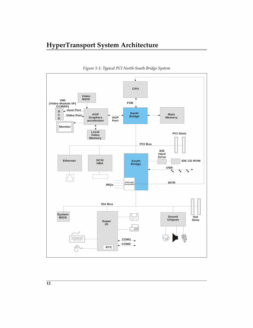
HyperTransport System Architecture
12
Figure 1-1: Typical PCI North-South Bridge System
CPU
PCI Bus
PCI Slots
NorthBridge Main
MemoryAGPPort
AGPGraphics
accelerator
VideoBIOS
DVD
Host Port
Video Port
Monitor
LocalVideo
Memory
SouthBridge
SCSIHBA
Ethernet
IDEHardDrive
IDE CD ROM
IRQs
USB
ISA Bus
ISASlots
SoundChipsetSuper
IO
RTC
COM1COM2
SystemBIOS
FSBCCIR601
VMI(Video Module I/F)
InterruptController INTR
Chapter 1: Introduction to HyperTransport
13
Until recently, the topology shown in Figure 1-1 on page 12 has been very popu-lar in desktop systems for a number of reasons, including:
1. A shared bus reduces the number of traces on the motherboard to a singleset.
2. All of the devices located on the PCI bus are only one bridge interface awayfrom the principal target of their transactions — main DRAM memory.
3. A single, very popular protocol (PCI) can be used for all embedded devices,add-in cards, and chipset components attached to the bus.
Unfortunately, some of the things that made this topology so popular also havemade it difficult to fix the I/O bandwidth problems which have become moreobvious as processors and memory have become faster.
A Shared Bus Runs At Limited Clock Speeds. The fact that multipledevices (including PCB connectors) attach to a shared bus means that tracelengths and electrical complexity will limit the maximum usable clock speed.For example, a generic PCI bus has a maximum clock speed of 33MHz; the PCISpecification permits increasing the clock speed to 66MHz, but the number ofdevices/connectors on the bus is very limited.
A Shared Bus May Be Host To Many Device Types. The require-ments of devices on a shared bus may vary widely in terms of bandwidthneeded, tolerance for bus access latency, typical data transfer size, etc. All of thiscomplicates arbitration on the bus when multiple masters wish to initiate trans-actions.
Backward Compatibility Prevents Upgrading Performance. If acritical shared bus is based on an open architecture, especially one that definesuser “add-in” connectors, then another problem in upgrading bus bandwidth isthe need to maintain backward compatibility with all of the devices and cardsalready in existence. If the bus protocol is enhanced and a user installs an “oldergeneration card”, then the bus must either revert back to the earlier protocol orlose its compatibility.
Special Problems If The Shared Bus Is PCI. As popular as it hasbeen, PCI presents additional problems that contribute to performance limits:
1. PCI doesn’t support split transactions, resulting in inefficient retries.2. Transaction size (there is no limit) isn’t known, which makes it difficult to
size buffers and causes frequent disconnects by targets. Devices are alsoallowed to insert numerous wait states during each data phase.
3. All PCI transactions by I/O devices targeting main memory generally
19
2 HT Architectural Overview
The Previous Chapter
To understand why HT was developed, it is helpful to review the previous gen-eration of I/O buses and interconnects. This chapter review the factors thatlimit the ability of older generation buses to keep pace with the increasingdemands of new applications. Finally, this chapter discusses the key factors ofthe HT technology that provides its improved capability.
This Chapter
This chapter provides an overview of the HT architecture that defines the pri-mary elements of HT technology and the relationship between these elements.This chapter summarizes the features, capabilities, and limitation of HT andprovides the background information necessary for in-depth discussions of thevarious HT topics in later chapters.
The Next Chapter
The next chapter describes the function of each signal in the high- and low-speed HyperTransport signal groups.
General
HyperTransport provides a point-to-point interconnect that can be extended tosupport a wide range of devices. Figure 2-1 on page 21 illustrates a sample HTsystem with four internal links. HyperTransport provides a high-speed,high-performance, point-to-point dual simplex link for interconnecting IC com-ponents on a PCB. Data is transmitted from one device to another across thelink.
HyperTransport System Architecture
20
The width of the link along with the clock frequency at which data is transferredare scalable:
• Link width ranges from 2 bits to 32-bits• Clock Frequency ranges from 200MHz to 800MHz (and 1GHz in the future)
This scalability allows for a wide range of link performance and potential appli-cations with bandwidths ranging from 200MB/s to 12.8GB/s.
At the current revision of the spec, 1.04, there is no support for connectorsimplying that all HyperTransport (HT) devices are soldered onto the mother-board. HyperTransport is technically an “inside-the-box” bus. In reality, connec-tors have been designed for systems that require board to board connections,and where analyzer interfaces are desired for debug.
Once again referring to Figure 2-1, the HT bus has been extended in the samplesystem via a series of devices known as tunnels. A tunnel is merely an HTdevice that performs some function, but in addition it contains a second HTinterface that permits the connection of another HT device. In Figure 2-1, thetunnel devices provide connections to other I/O buses:
• Infiniband• PCI-X• Ethernet
The end device is termed a cave, which always represents the termination of achain of devices that all reside on the same HT bus. Cave devices include a func-tion, but no additional HT connection. The series of devices that comprise anHT bus is sometimes simply referred to as an HT chain.
Additional HT buses (i.e. chains) may be implemented in a given system byusing a HT-to-HT bridge. In this way, a fabric of HT devices may be imple-mented. Refer to section entitled, “Extending the Topology” on page 33 foradditional detail.
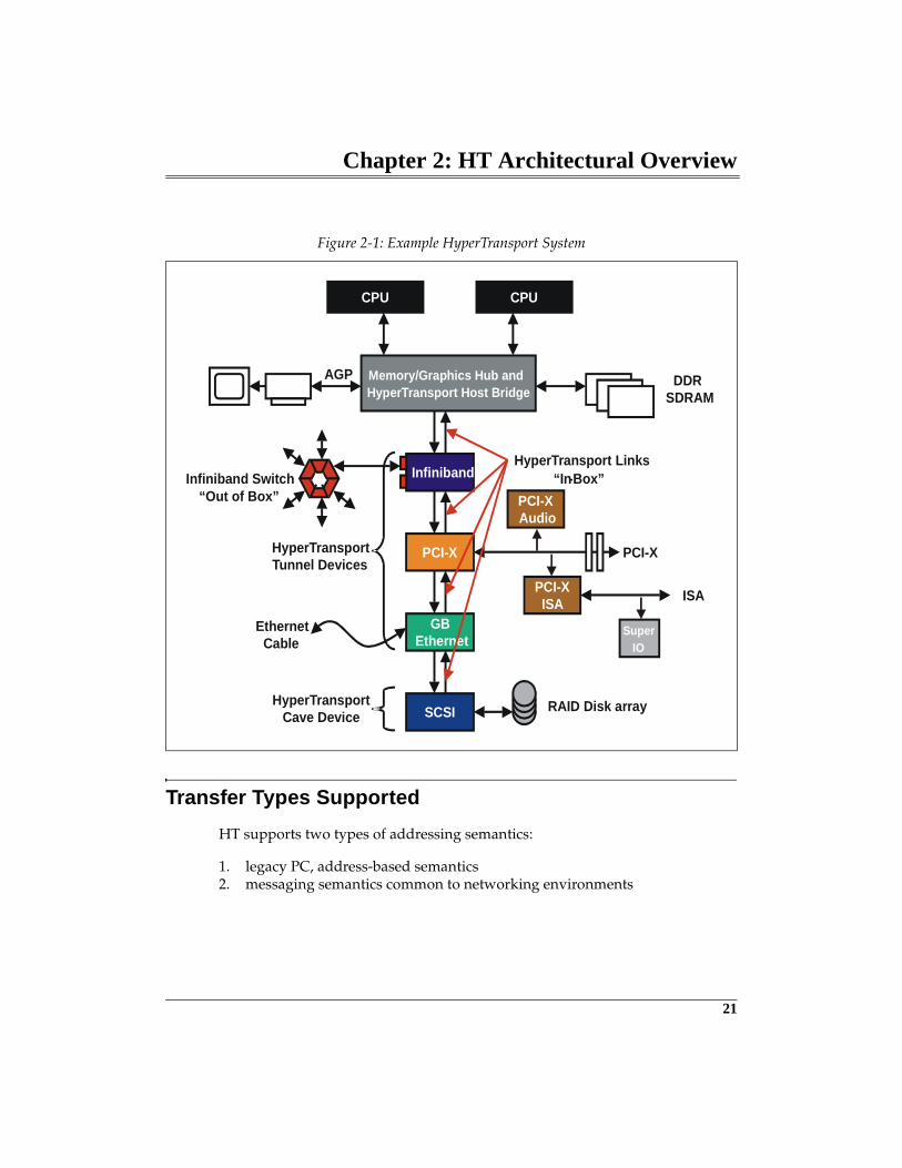
Chapter 2: HT Architectural Overview
21
Transfer Types Supported
HT supports two types of addressing semantics:
1. legacy PC, address-based semantics2. messaging semantics common to networking environments
Figure 2-1: Example HyperTransport System
CPU CPU
Memory/Graphics Hub and HyperTransport Host Bridge
AGP DDR SDRAM
Infiniband
PCI-X
GBEthernet
PCI-X
Infiniband Switch
SCSI RAID Disk array
PCI-XISA ISA
SuperIO
HyperTransportTunnel Devices
PCI-XAudio
HyperTransportCave Device
HyperTransport Links
EthernetCable
“Out of Box”“In-Box”
HyperTransport System Architecture
22
The first part of this book discusses the address-based semantics common tocompatible PC implementations. Message-passing semantics are discussed inChapter 19, entitled "Networking Extensions Overview," on page 443.
Address-Based Semantics
The HT bus was initially implemented as a PC compatible solution that by defi-nition uses Address-based semantics. This includes a 40-bit, or 1 Terabye (TB)address space. Transactions specify locations within this address space that areto be read from or written to. The address space is divided into blocks that areallocated for particular functions, listed in Figure 2-2 on page 23.
HyperTransport does not contain dedicated I/O address space. Instead, CPUI/O space is mapped to high memory address range (FD_FC00_0000h—FD_FDFF_FFFFh). Each HyperTransport device is configured at initializationtime by the boot ROM configuration software to respond to a range of memoryaddress spaces. The devices are assigned addresses via the base address regis-ters contained in the configuration register header. Note that these registers arebased on the PCI Configuration registers, and are also mapped to memoryspace (FD_FE00_0000h—FD_FFFF_FFFFh. Unlike the PCI bus, there is no dedi-cated configuration address space.
Read and write request command packets contain a 40-bit address Addr[39:2].Additional memory address ranges are used for interrupt signaling and systemmanagement messages. Details regarding the use of each range of address spaceis discussed in subsequent chapters that cover the related topic. For example, adetailed discussion of the configuration address space can be found in Chapter13, entitled "Device Configuration," on page 305.
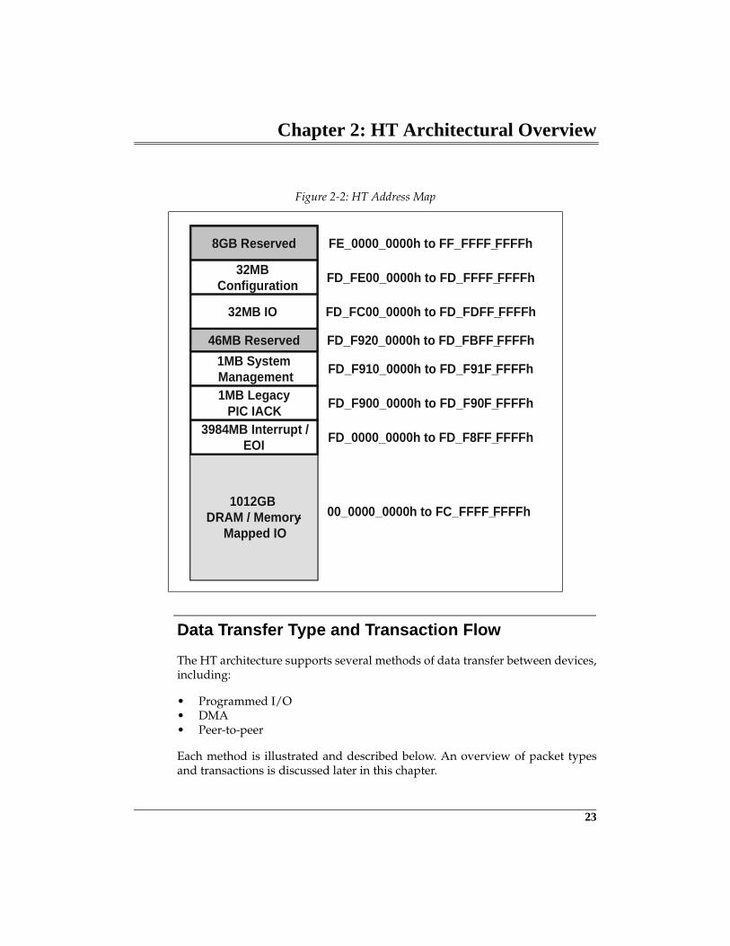
Chapter 2: HT Architectural Overview
23
Data Transfer Type and Transaction Flow
The HT architecture supports several methods of data transfer between devices,including:
• Programmed I/O• DMA• Peer-to-peer
Each method is illustrated and described below. An overview of packet typesand transactions is discussed later in this chapter.
Figure 2-2: HT Address Map
1012GBDRAM / Memory-
Mapped IO
3984MB Interrupt /EOI
1MB LegacyPIC IACK
1MB SystemManagement
46MB Reserved
8GB Reserved
32MBConfiguration
32MB IO
00_0000_0000h to FC_FFFF_FFFFh
FD_0000_0000h to FD_F8FF_FFFFh
FD_F900_0000h to FD_F90F_FFFFh
FD_F910_0000h to FD_F91F_FFFFh
FD_F920_0000h to FD_FBFF_FFFFh
FD_FC00_0000h to FD_FDFF_FFFFh
FD_FE00_0000h to FD_FFFF_FFFFh
FE_0000_0000h to FF_FFFF_FFFFh
53
3 Signal Groups
The Previous ChapterThe previous chapter provided an overview of the HT architecture that definesthe primary elements of HT technology and the relationship between these ele-ments. The chapter summarized the features, capabilities, and limitation of HTand provided the background information necessary for in-depth discussions ofthe various HT topics in later chapters.
This ChapterThis chapter describes the function of each signal in the high and low speedHyperTransport signal groups. The CAD, CTL, and CLK high speed signals arerouted point-to-point as low-voltage differential pairs between two devices (orbetween a device and a connector in some cases). The RESET#, PWROK,LDTREQ#, and LDTSTOP# low speed signals are single-ended low voltageCMOS and may be bused to multiple devices. In addition, each device requirespower supply and ground pins. Because the CAD bus width is scalable, theactual number of CAD and CLK signal pairs varies, as does the number ofpower and ground pins to the device.
The Next ChapterThe next chapter describes the use of HyperTransport control and data packets toconstruct HyperTransport link transactions. Control packet types include Infor-mation, Request, and Response variants; data packets contain a payload of 0-64valid bytes. The transmission, structure, and use of each packet type is pre-sented.
IntroductionSignals on each HyperTransport link fall into two groups: high speed signalsassociated with the sending and receiving of control and data packets, and mis-cellaneous low-speed signals required for such things as reset and power man-agement. Whereas the low speed signals are not scalable and employconventional low voltage CMOS signalling, the high speed signal group is scal-
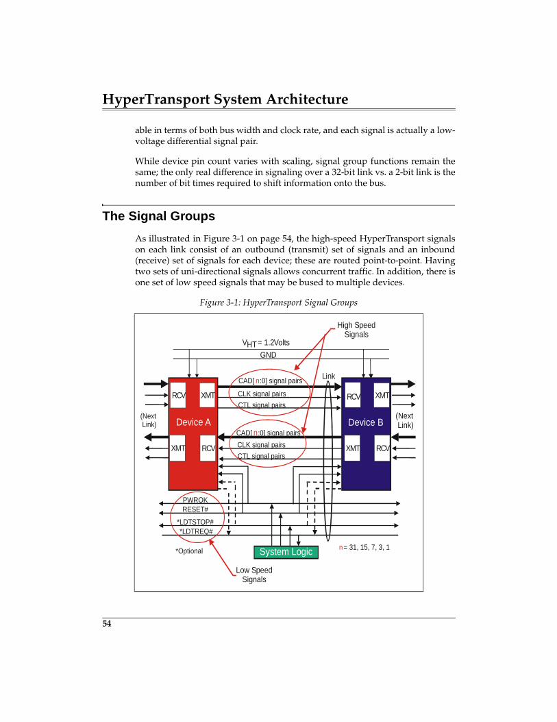
HyperTransport System Architecture
54
able in terms of both bus width and clock rate, and each signal is actually a low-voltage differential signal pair.
While device pin count varies with scaling, signal group functions remain thesame; the only real difference in signaling over a 32-bit link vs. a 2-bit link is thenumber of bit times required to shift information onto the bus.
The Signal Groups
As illustrated in Figure 3-1 on page 54, the high-speed HyperTransport signalson each link consist of an outbound (transmit) set of signals and an inbound(receive) set of signals for each device; these are routed point-to-point. Havingtwo sets of uni-directional signals allows concurrent traffic. In addition, there isone set of low speed signals that may be bused to multiple devices.
Figure 3-1: HyperTransport Signal Groups
Link
CTL signal pairs
CAD[ n:0] signal pairs
CLK signal pairs
CTL signal pairs
CAD[ n:0] signal pairsCLK signal pairsRCV
XMT
XMT
RCV
System Logic
PWROKRESET#
*LDTSTOP#*LDTREQ#
*Optional
Low SpeedSignals
VHT = 1.2VoltsGND
High SpeedSignals
(Next Link)
(Next Link)
n= 31, 15, 7, 3, 1
XMT
RCV
Device A Device B
XMT
RCV
RCV
XMT
Chapter 3: Signal Groups
55
The High Speed Signals (One Set In Each Direction)
Each high-speed signal is actually a differential signal pair. CAD (Command/Address/Data) information consists of the two basic types of HyperTransportpackets: control and data. When a link transmitter sends packets on the CADbus, the receive side of the interface uses the CLK and CTL signals, also sup-plied by the transmitter, to latch in packet information during each bit time.CTL distinguishes control packets from data packets.
The CAD Signal Group
The CAD bus is always driven by the transmitter side of a link, and is com-prised of signal pairs that carry HyperTransport requests, responses, and data.Each CAD bus may consist of between 2 bits (two differential signal pairs) and32 bits (thirty-two differential signal pairs). The HyperTransport specificationpermits the CAD bus width to be different (asymmetrical) for the two direc-tions. To enable the corresponding receiver to make a distinction as to the typeof information currently being sent over the CAD bus, the transmitter alsodrives the CTL signal (see the following description).
Control Signal (CTL)
This signal pair is driven by the transmitter to qualify the information beingsent concurrently over the CAD signals. If this signal is asserted (high), thetransmitter is indicating that it is sending a control packet; if deasserted, thetransmitter is sending a data packet. The receiver uses this information whenrouting incoming CAD information to appropriate request queues, data buffers,etc. There is one (and only one) CTL signal for each link direction, regardless ofthe width of the CAD bus.
Clock Signal(s) (CLK)
As a source-synchronous connection, each HyperTransport transmitter sends adifferential clock signal along with CAD and CTL signals to the receiver at theother end of the link. There is one CLK signal pair for each byte of CAD width.While the timing on each clock pair is the same, replicating clocks help in rout-ing of CAD signal pairs with respect to their clock signals. The current Hyper-Transport specification allows clock speeds from 200MHz (default) to 800MHz.
HyperTransport System Architecture
56
Scaling Hazards: Burden Is On The Transmitter
It is a requirement in HyperTransport that the transmitter side of each link mustbe aware of the capabilities of its corresponding receiver and avoid the doublehazard of a scalable bus: running at a faster clock rate than the receiver can han-dle or using a wider data path than the receiver supports. Because the link is nota shared bus, the transmitter side of each device is concerned with the capabili-ties of only one target. Refer to “Link Initialization” on page 282 for a descrip-tion of how HyperTransport links are initialized and configured to avoid theseproblems.
The Low Speed Signals
Power OK (PWROK) And Reset (RESET#)
PWROK used with RESET# indicates to HyperTransport devices whether a Coldor Warm Reset is in progress. Which system logic component is responsible formanaging the PWROK and RESET# signals is beyond the scope of the Hyper-Transport specification, but timing and use of the signals are defined. The basicuse of the signals includes:
• At power up, PWROK is asserted by system logic when it can be guaran-teed that system power and clocks related to HyperTransport are withinproper limits.
• RESET# is asserted by system logic to indicate that a reset is required. Thestate of PWROK when RESET# is seen asserted indicates the type of reset tobe performed. PWROK and RESET# both asserted is a warm reset; PWROKdeasserted and RESET# asserted indicates cold reset.
• After initial system power up, reset, and initialization, a cold or warm resetmay also be generated under software control writing configuration regis-ters in the host bridge.
The HyperTransport specification describes the actions to be taken by devicesduring either type of reset event. Refer to Chapter 12, entitled "Reset & Initial-ization," on page 275 for a thorough discussion of how PWROK and RESET areused during system power-up and initialization.
Chapter 3: Signal Groups
57
LDTSTOP#
(Note: the signal names LDTSTOP# and LDTREQ# were carried forward from the ear-lier name AMD assigned to HyperTransport technology — Lightning Data Transfer).
LDTSTOP# is an input to HyperTransport devices which is asserted by systemlogic to enable and disable link activity during power management state transi-tions. Support for this signal is optional for HyperTransport devices.
A transmitter which detects LDTSTOP# asserted finishes sending any controlpacket in progress, then commences a disconnect NOP sequence followed bydisabling its output drivers (if so enabled in the transmitter’s ConfigurationSpace Tri-State Enable Bit). Upon receipt of the disconnect NOP sequence, thetarget also turns off its input receivers (if similarly enabled in it’s ConfigurationSpace Tri-State Enable Bit).
Later, when the transmitter detects LDTSTOP# deasserted, it re-enables its driv-ers and begins the initialization sequence. A receiver that responds to LDT-STOP# deasserted turns its input receivers on.
LDTREQ#
LDTREQ# is a wire-or’d output from HyperTransport devices that is used torequest system logic to re-enable links previously disabled using the LDTSTOP#mechanism. Upon receipt of the LDTREQ# signal from one or more Hyper-Transport devices, system logic (typically the South Bridge) deasserts LDT-STOP# which triggers the sequence described previously. Specifically, theLDTREQ# signal indicates that a HyperTransport transaction is required some-where in a system that is currently in the ACPI C3 state; the system is requiredto transition to the C0 state. Support for this signal is optional for HyperTrans-port devices.
Where Are The Interrupt, Error, And Wait State Signals?
The HyperTransport specification eliminates a number of control signals thatare commonly found on other buses. While devices are not prohibited fromimplementing signals beyond those defined in the specification, HyperTrans-port is a generic, simple interface and handles interrupts, errors, and data waitstates in the following general way:
59
4 Packet Protocol
The Previous ChapterThe previous chapter described the function of each signal in the high and lowspeed HyperTransport signal groups. The CAD, CTL, and CLK high speed sig-nals are routed point-to-point as low-voltage differential pairs between twodevices (or between a device and a connector in some cases). The RESET#,PWROK, LDTREQ#, and LDTSTOP# low speed signals are single-ended lowvoltage CMOS and may be bused to multiple devices. In addition, each devicerequires power supply and ground pins. Because the CAD bus width is scal-able, the actual number of CAD and CLK signal pairs varies, as does the num-ber of power and ground pins to the device.
This ChapterThis chapter describes the use of HyperTransport control and data packets toconstruct HyperTransport link transactions. Control packet types include Infor-mation, Request, and Response variants; data packets contain a payload of 0-64valid bytes. The transmission, structure, and use of each packet type is pre-sented.
The Next ChapterThe next chapter describes HyperTransport flow control, used to throttle themovement of packets across each link interface. On a high-performance connec-tion such as HyperTransport, efficient management of transaction flow is nearlyas important as the raw bandwidth made possible by clock speed and data buswidth. Topics covered here include background information on bus flow controland the initialization and use of the HyperTransport virtual channel flow con-trol buffer mechanism defined for each transmitter-receiver pair.
HyperTransport System Architecture
60
The Packet-Based Protocol
HyperTransport employs a packet-based protocol in which all information —address, commands, and data — travel in packets which are multiples of fourbytes each. Packets are used in link management (e.g. flow control and errorreporting) and as building blocks in constructing more complex transactionssuch as read and write data transfers.
It should be noted that, while packet descriptions in this chapter are in terms ofbytes, the link’s bidirectional interface width (2, 4, 8, 16, or 32 bits) ultimatelydetermines the amount of packet information sent during each bit time onHyperTransport links. There are two bit times per clock period.
Before looking at packet function and use, the following sections describe themechanics of packet delivery over 2,4,8,16, and 32 bit scalable link interfaces.
8 Bit Interfaces
For 8-bit interfaces, one byte of packet information may be sent in each bit time.For example, a 4-byte request packet would be sent by the transmitter duringfour adjacent bit times, least significant byte first as shown in Figure 4-1 on page61. Total time to complete a four-byte packet is two clock periods.
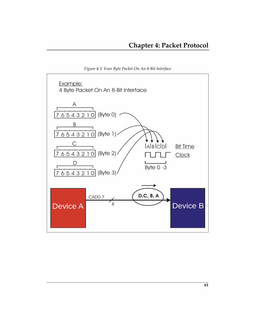
Chapter 4: Packet Protocol
61
Figure 4-1: Four Byte Packet On An 8-Bit Interface
Bit Time
Clock
Byte 0 -3
0
0
0
0
7
7
7
7
A
A B C D
(Byte 0)
Example:4 Byte Packet On An 8-Bit Interface
(Byte 1)
(Byte 2)
(Byte 3)
1
1
1
1
2
2
2
2
B
C
D
Device A Device BCAD0-7
8
D,C, B, A
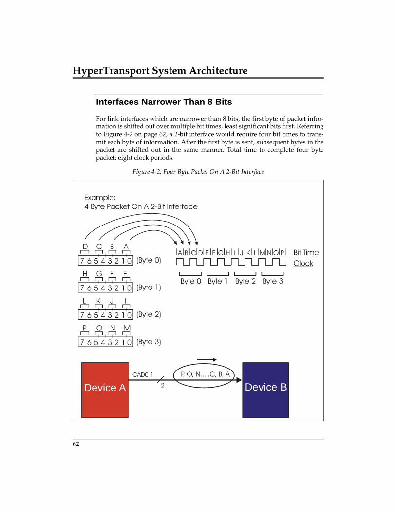
HyperTransport System Architecture
62
Interfaces Narrower Than 8 Bits
For link interfaces which are narrower than 8 bits, the first byte of packet infor-mation is shifted out over multiple bit times, least significant bits first. Referringto Figure 4-2 on page 62, a 2-bit interface would require four bit times to trans-mit each byte of information. After the first byte is sent, subsequent bytes in thepacket are shifted out in the same manner. Total time to complete four bytepacket: eight clock periods.
Figure 4-2: Four Byte Packet On A 2-Bit Interface
Bit TimeClock
Byte 0 Byte 1 Byte 2 Byte 3
0
0
0
0
7
7
7
7
D
H
L
P
C
G
K
O
B
F
J
N
AA B C D E F G H I J K L M N O P
E
(Byte 0)
Example:4 Byte Packet On A 2-Bit Interface
(Byte 1)
(Byte 2)
(Byte 3)
1
1
1
1
2
2
2
2
P, O, N.....C, B, A
Device A Device BCAD0-1
2
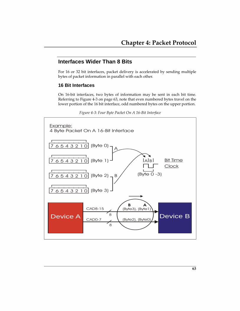
Chapter 4: Packet Protocol
63
Interfaces Wider Than 8 Bits
For 16 or 32 bit interfaces, packet delivery is accelerated by sending multiplebytes of packet information in parallel with each other.
16 Bit Interfaces
On 16-bit interfaces, two bytes of information may be sent in each bit time.Referring to Figure 4-3 on page 63, note that even numbered bytes travel on thelower portion of the 16 bit interface, odd numbered bytes on the upper portion.
Figure 4-3: Four Byte Packet On A 16-Bit Interface
Device A Device B8
Bit TimeClock
(Byte 0 -3)
0
0
0
0
7
7
7
7
A
CAD0-7
(Byte 0)
Example:4 Byte Packet On A 16-Bit Interface
(Byte 1)
(Byte 2)
(Byte 3)
1
1
1
1
2
2
2
2
B
8
(Byte3), (Byte1)
A B
B ACAD8-15
(Byte2), (Byte0)
99
5 Flow Control
The Previous ChapterThe previous chapter described the use of HyperTransport control and datapackets to construct HyperTransport link transactions. Control packet typesinclude Information, Request, and Response variants; data packets contain apayload of 0-64 valid bytes. The transmission, structure, and use of each packettype is presented.
This ChapterThis chapter describes HyperTransport flow control, used to throttle the move-ment of packets across each link interface. On a high-performance connectionsuch as HyperTransport, efficient management of transaction flow is nearly asimportant as the raw bandwidth made possible by clock speed and data buswidth. Topics covered here include background information on bus flow controland the initialization and use of the HyperTransport virtual channel flow con-trol buffer mechanism defined for each transmitter-receiver pair.
The Next ChapterThe next chapter describes the rules governing acceptance, forwarding, andrejection of packets seen by HyperTransport devices. Several factors come intoplay in routing, including the packet type, the direction it is moving, and thedevice type which sees it. A related topic also covered in this chapter is the fair-ness algorithm used by a tunnel device as it inserts its own packets into the traf-fic it forwards upstream on behalf of devices below it. The HyperTransportspecification provides a fairness algorithm and a hardware method for tunnelmanagement packet insertion.
The Problem
On any bus where an agent initiates the exchange of information (commands,data, status, etc.) with a target, a number of things can cause a delay (or evenend) the normal completion of the intended transfer. The throttling of informa-tion delivery on a bus is referred to as flow control. PCI is a good example of a
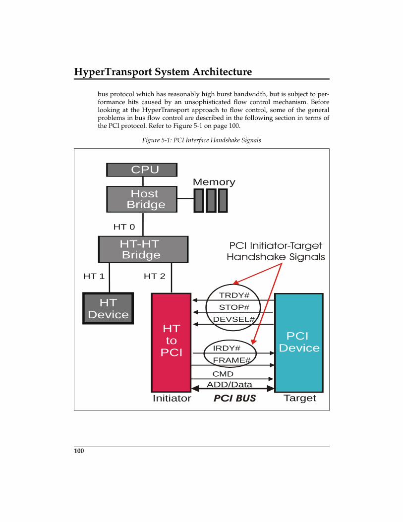
HyperTransport System Architecture
100
bus protocol which has reasonably high burst bandwidth, but is subject to per-formance hits caused by an unsophisticated flow control mechanism. Beforelooking at the HyperTransport approach to flow control, some of the generalproblems in bus flow control are described in the following section in terms ofthe PCI protocol. Refer to Figure 5-1 on page 100.
Figure 5-1: PCI Interface Handshake Signals
CPUMemory
HT Device
Host Bridge
HT-HTBridge
HT-PCI
HT 2
ADD/Data
TRDY#
Initiator Target
HT 1
HT 0
STOP#DEVSEL#
PCI Device
HTto
PCI
IRDY#FRAME#
CMD
PCI BUS
PCI Initiator-TargetHandshake Signals
Chapter 5: Flow Control
101
How PCI Handles Flow Control
While the PCI specification permits 64-bit data bus and 66MHz clock options, ageneric PCI bus carries only 32 bits (4 bytes) of data and runs at a 33MHz clockspeed. This means that the burst bandwidth for this bus is 132MB/s (4 bytes x33MHz = 132MB/s). In many systems the PCI bus is populated by all sorts ofhigh- and low-performance peripherals such as hard drives, graphics adapters,and serial port adapters. All PCI bus master devices must take turns accessingthe shared bus and performing their transfers. The priority of a bus master inaccessing the bus and the amount of time it is allowed to retain control of thebus is a function of PCI arbitration. In a typical computer system, the PCI arbiterlogic resides in the system chipset.
Once a PCI bus master has won arbitration and verifies the bus is idle, it com-mences its transaction. After decoding the address and command sent by themaster, one target claims the cycle by asserting a signal called DEVSEL#. At thispoint, if both devices are prepared, either write data will be sent by the initiatoror read data will be returned by the target. For cases where either the master ortarget are not prepared for full-speed transfer of some or all of the data, flowcontrol comes into play. In PCI there are a number of cases that must be dealtwith.
PCI Target Flow Control Problems
PCI Target Not Ready To Start. In some cases, a PCI device being tar-geted for transmission is not prepared to transfer any data at all. This couldhappen if the target is off-line, does not have buffer space for write data beingsent to it, or does not have requested read data available. It may also occur if thetransaction must cross a bridge device to a different bus. Many bus protocols,including PCI, place a limit on how long the bus may be stalled before complet-ing a transaction; in cases where a target can’t meet the requirement for even thefirst data, a mechanism is required to indicate the transaction should be aban-doned and re-attempted later. PCI calls the target cancellation of a transaction(without transferring any data) a Retry; a Retry is indicated when a targetasserts the STOP# signal (instead if TRDY#) in the first data phase.
PCI Target Starts Data Transfer, But Can’t Continue. Another pos-sibility is that a transaction started properly, some data has transferred, but atsome point before completion the target “realizes” it can’t continue the transferwithin the time allowed by the protocol. The target must indicate to the masterthat the transaction must be suspended (and resumed later at the point where it
HyperTransport System Architecture
102
left off). PCI calls this target suspension of a transaction (with a partial transferof data) a Disconnect. A Disconnect is signalled when the target asserts theSTOP# signal in a data phase after the first one.
PCI Target Starts, Can Continue, But Needs More Time. Some-times a transaction is underway and the target requires additional time to com-plete transmission of a particular data item; in this case, it does not need tosuspend the transaction altogether, but simply stretch one or more data phases.The generic name for this is wait-state insertion. Wait states are a reasonablealternative to Retry and Disconnect if there are not too many of them; whenthere are excessive wait states, bus performance would be better served by thedevices giving up the bus and allowing it to be used by other devices while theyprepare for the resumption of the suspended transaction. PCI targets de-assertthe TRDY# signal during any data phase to indicate wait states. A target mustbe prepared to complete each data phase within 8 PCI clocks (maximum ofseven wait states), except for the first data phase which it must complete within16 clocks. If a target cannot meet the “16 and 8 tick” rules for completing a dataphase, it must signal Retry or Disconnect instead.
PCI Initiator Flow Control Problems
While many flow control problems are associated with the target of a transac-tion, there are a couple which may occur on the initiator side. Again, the casesare described in terms of PCI protocol.
PCI Initiator Starts, But Can’t Continue. Some bus protocols alsoallow an initiator to break off a transaction early in the event it can’t accept thenext read data or source the next write data within the time allowed by the pro-tocol — even with wait states. PCI initiators suspend transactions simply by de-asserting the FRAME# signal early. As a rule, the master will re-arbitrate laterfor the PCI bus and perform a new transaction which picks up from where it leftoff previously.
PCI Initiator Starts, Can Continue, But Needs Wait-States. Somebus protocols allow an initiator to insert wait states in a transfer, just as the tar-get may. Other bus protocols (e.g. PCI-X) only allow targets to insert wait states— based on the assumption that a device which starts a transaction should beready to complete it before requesting the bus. In any case, PCI initiators de-assert the IRDY# signal to indicate wait states. An initiator must be prepared tocomplete each data phase within 8 clocks (maximum of seven wait states); if itcan’t meet this rule for any data phase, it must instead suspend the transactionby de-asserting FRAME#.
Chapter 5: Flow Control
103
All PCI Flow Control Problems Hurt Performance
Each of the initiator and target flow control problems just described impact PCIbus performance for both the devices involved in the transfer, and for deviceswaiting to access the bus. While not every transaction is afflicted with targetretries and disconnects, or early de-assertion of FRAME# by initiators, they hap-pen enough to make effective bandwidth considerably less than 132MB/s onthe PCI bus. In addition, arbitration and flow control uncertainties make systemperformance difficult to estimate.
HyperTransport Flow Control: Overview
All of the flow control problems described previously for PCI severely hurt busperformance and would be even less acceptable on a very high-performanceconnection. The flow control scheme used in HyperTransport applies indepen-dently to each transmitter-receiver pair on each link. The basic features includethe following.
Packets Never Start Unless Completion Assured
All transfers across HyperTransport links are packet based. No link transmitterever starts a packet transfer unless it is known the packet can be accepted by thereceiver. This is accomplished with the “coupon based” flow control schemedescribed in this section, and eliminates the need for the Retry and Disconnectmechanisms used in PCI.
Transfer Length Is Always Known
Hypertransport control packets have a fixed size (four or eight bytes) and datapackets have a known and maximum transfer length, unlike PCI data transfers.This makes buffer sizing and flow control much more straightforward as bothtransmitter and receiver are aware of their actual transfer commitments. It alsomakes the interleaving of control packets with data packets much simpler.
119
6 I/O Ordering
The Previous ChapterThe previous chapter described the rules governing acceptance, forwarding,and rejection of packets seen by HyperTransport devices. Several factors comeinto play in routing, including the packet type, the direction it is moving, andthe device type which sees it. A related topic also covered in this chapter is thefairness algorithm used by a tunnel device as it inserts its own packets into thetraffic it forwards upstream on behalf of devices below it. The HyperTransportspecification provides a fairness algorithm and a hardware method for tunnelmanagement packet insertion.
This ChapterThis chapter describes the ordering rules which apply to packets associatedwith the three types of HyperTransport I/O traffic: PIO, DMA, and Peer-to-Peer. Depending on whether compatibility with the full producer-consumerordering model used in PCI is required or relaxed ordering is permissible,attribute bits in request and response packets may be set or cleared. These bitsare defined by the requester and are used by devices in the path to the target,and within the target, to enforce proper ordering. HyperTransport applies dedi-cated sets of ordering rules for upstream I/O traffic, downstream I/O traffic,and the special ordering required of host bridges and in double-hosted chains.Refer to Chapter 20, entitled "I/O Compatibility," on page 457 for a descriptionof the additional ordering requirements when interfacing HyperTransport toother compatible protocols (e.g. PCI, PCI-X, and AGP).
The Next ChapterIn the next chapter, examples are presented which apply the packet principlesdescribed in the preceding chapter. The examples also entail more complex sys-tem transactions than discussed previously, including reads, posted and non-posted writes, and atomic read-modify-write operations.
HyperTransport System Architecture
120
The Purpose Of Ordering Rules
Some of the important reasons for enforcing ordering rules on packets movingthrough HyperTransport include the following:
Maintain Data Coherency
If transactions are in some way dependent on each other, a method is requiredto assure that they complete in a deterministic way. For example, if Device Aperforms a write transaction targeting main memory and then follows it with aread request targeting the same location, what data will the read transactionreturn? HyperTransport ordering seeks to make such events predictable (deter-ministic) and to match the intent of the programmer. Note that, compared to ashared bus such as PCI, HyperTransport transaction ordering is complicatedsomewhat by point-to-point connections which result in target devices on thesame chain (logical bus) being at different levels of fabric hierarchy.
Avoid Deadlocks
Another reason for ordering rules is to handle cases where the completion oftwo separate transactions are each dependent on the other completing first.HyperTransport ordering includes a number of rules for deadlock avoidance.Some of the rules are in the specification because of known deadlock hazardsassociated with other buses to which HyperTransport may interface (e.g. PCI).
Support Legacy buses
One of the principal roles of HyperTransport is to serve as a backbone buswhich is bridged to other peripheral buses. HyperTransport explicitly supportsPCI, PCI-X, and AGP and the ordering requirements of those buses.
Maximize Performance
Finally, HyperTransport permits devices in the path to the target, and the targetitself, some flexibility in reordering packets around each other to enhance per-formance. When acceptable, relaxed ordering may be enabled by the requesteron a per-transaction basis using attribute bits in request and response packets.
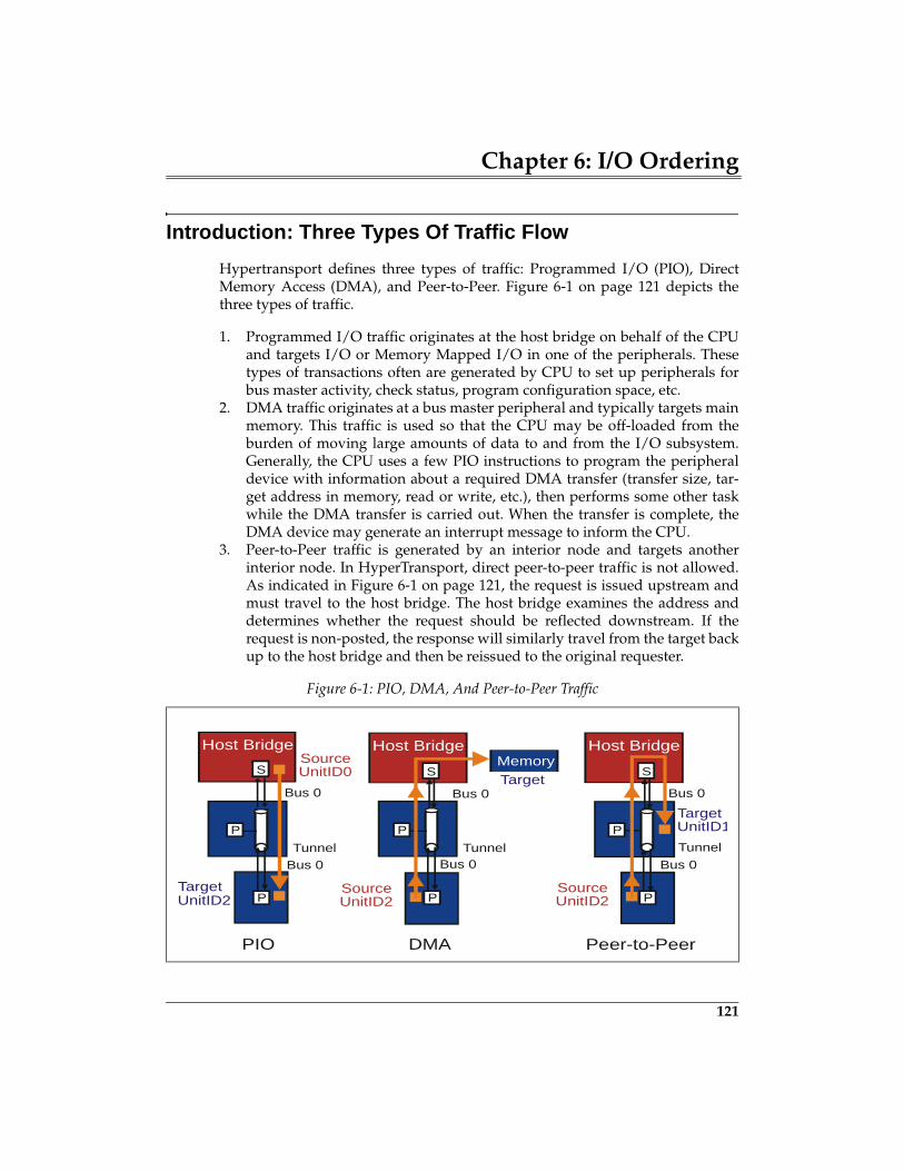
Chapter 6: I/O Ordering
121
Introduction: Three Types Of Traffic Flow
Hypertransport defines three types of traffic: Programmed I/O (PIO), DirectMemory Access (DMA), and Peer-to-Peer. Figure 6-1 on page 121 depicts thethree types of traffic.
1. Programmed I/O traffic originates at the host bridge on behalf of the CPUand targets I/O or Memory Mapped I/O in one of the peripherals. Thesetypes of transactions often are generated by CPU to set up peripherals forbus master activity, check status, program configuration space, etc.
2. DMA traffic originates at a bus master peripheral and typically targets mainmemory. This traffic is used so that the CPU may be off-loaded from theburden of moving large amounts of data to and from the I/O subsystem.Generally, the CPU uses a few PIO instructions to program the peripheraldevice with information about a required DMA transfer (transfer size, tar-get address in memory, read or write, etc.), then performs some other taskwhile the DMA transfer is carried out. When the transfer is complete, theDMA device may generate an interrupt message to inform the CPU.
3. Peer-to-Peer traffic is generated by an interior node and targets anotherinterior node. In HyperTransport, direct peer-to-peer traffic is not allowed.As indicated in Figure 6-1 on page 121, the request is issued upstream andmust travel to the host bridge. The host bridge examines the address anddetermines whether the request should be reflected downstream. If therequest is non-posted, the response will similarly travel from the target backup to the host bridge and then be reissued to the original requester.
Figure 6-1: PIO, DMA, And Peer-to-Peer Traffic
MemoryTarget
SourceUnitID0
TargetUnitID2
Host Bridge Host Bridge
S
P
TunnelTunnel
Bus 0Bus 0
Bus 0Bus 0
Bus 0
Bus 0
SourceSourceUnitID2 UnitID2
TargetUnitID1
Peer-to-PeerDMAPIO
Tunnel
P P
P
S
Host Bridge
S
P P
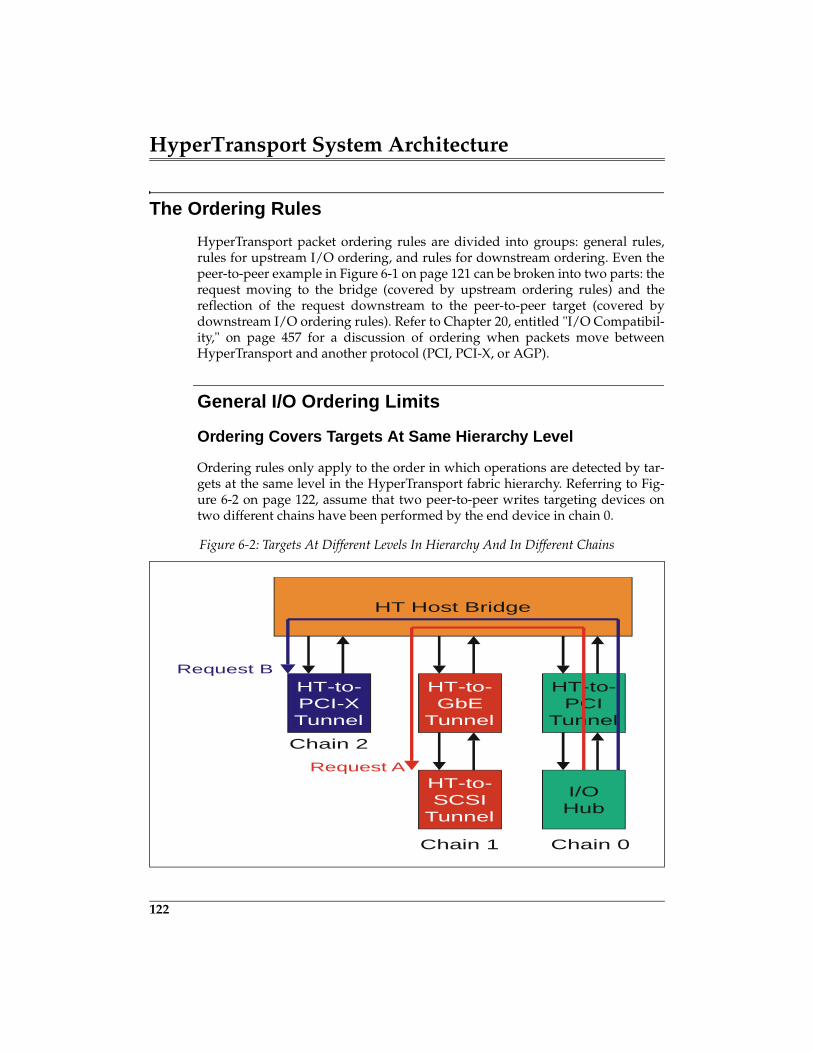
HyperTransport System Architecture
122
The Ordering Rules
HyperTransport packet ordering rules are divided into groups: general rules,rules for upstream I/O ordering, and rules for downstream ordering. Even thepeer-to-peer example in Figure 6-1 on page 121 can be broken into two parts: therequest moving to the bridge (covered by upstream ordering rules) and thereflection of the request downstream to the peer-to-peer target (covered bydownstream I/O ordering rules). Refer to Chapter 20, entitled "I/O Compatibil-ity," on page 457 for a discussion of ordering when packets move betweenHyperTransport and another protocol (PCI, PCI-X, or AGP).
General I/O Ordering Limits
Ordering Covers Targets At Same Hierarchy Level
Ordering rules only apply to the order in which operations are detected by tar-gets at the same level in the HyperTransport fabric hierarchy. Referring to Fig-ure 6-2 on page 122, assume that two peer-to-peer writes targeting devices ontwo different chains have been performed by the end device in chain 0.
Figure 6-2: Targets At Different Levels In Hierarchy And In Different Chains
HT Host Bridge
HT-to-PCI-XTunnel
HT-to-GbE
Tunnel
HT-to-PCI
Tunnel
HT-to-SCSI
Tunnel
Chain 1
Chain 2
Chain 0
Request A
Request B
I/OHub
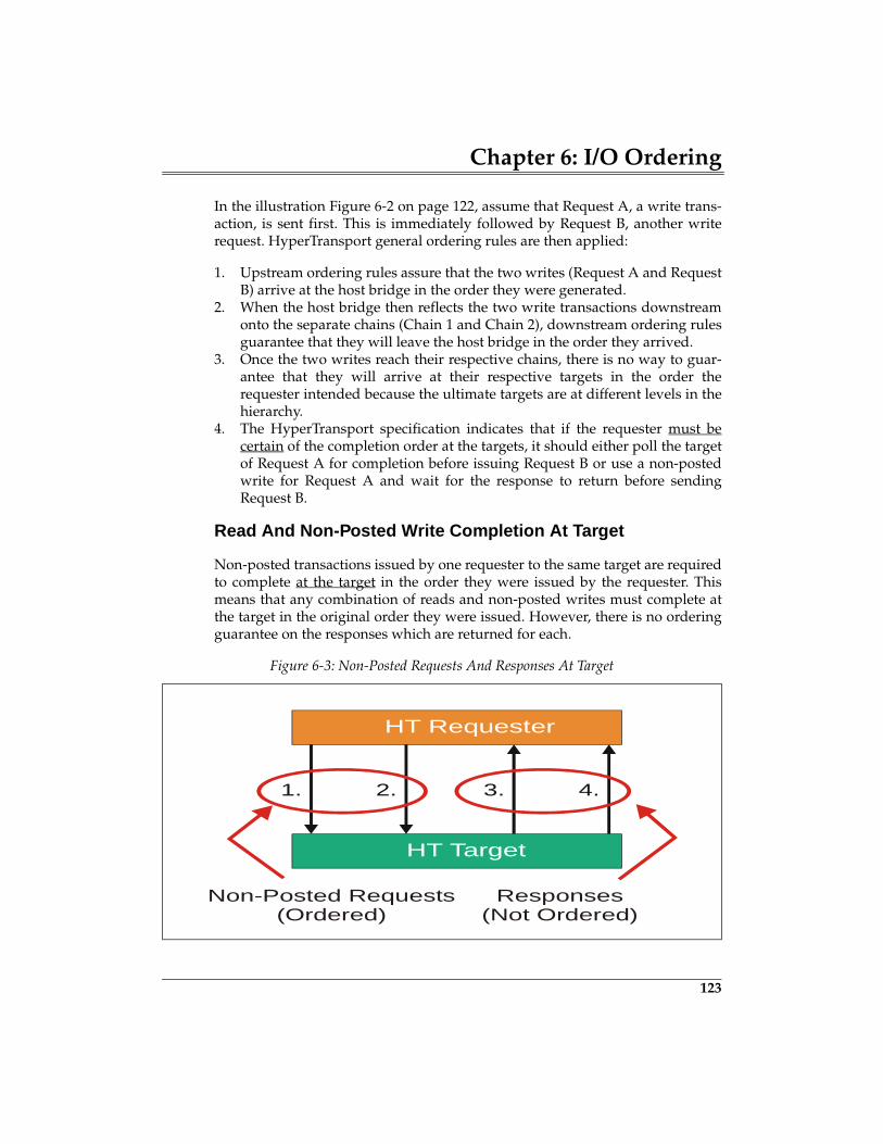
Chapter 6: I/O Ordering
123
In the illustration Figure 6-2 on page 122, assume that Request A, a write trans-action, is sent first. This is immediately followed by Request B, another writerequest. HyperTransport general ordering rules are then applied:
1. Upstream ordering rules assure that the two writes (Request A and RequestB) arrive at the host bridge in the order they were generated.
2. When the host bridge then reflects the two write transactions downstreamonto the separate chains (Chain 1 and Chain 2), downstream ordering rulesguarantee that they will leave the host bridge in the order they arrived.
3. Once the two writes reach their respective chains, there is no way to guar-antee that they will arrive at their respective targets in the order therequester intended because the ultimate targets are at different levels in thehierarchy.
4. The HyperTransport specification indicates that if the requester must becertain of the completion order at the targets, it should either poll the targetof Request A for completion before issuing Request B or use a non-postedwrite for Request A and wait for the response to return before sendingRequest B.
Read And Non-Posted Write Completion At Target
Non-posted transactions issued by one requester to the same target are requiredto complete at the target in the order they were issued by the requester. Thismeans that any combination of reads and non-posted writes must complete atthe target in the original order they were issued. However, there is no orderingguarantee on the responses which are returned for each.
Figure 6-3: Non-Posted Requests And Responses At Target
HT Requester
HT Target
1. 2. 3. 4.
Non-Posted Requests(Ordered)
Responses(Not Ordered)
139
7 Transaction Examples
The Previous ChapterThe previous chapter described the ordering rules which apply to packets asso-ciated with the three types of HyperTransport I/O traffic: PIO, DMA, and Peer-to-Peer. Depending on whether compatibility with the full producer-consumerordering model used in PCI is required or relaxed ordering is permissible,attribute bits in request and response packets may be set or cleared. These bitsare defined by the requester and are used by devices in the path to the target,and within the target, to enforce proper ordering. HyperTransport applies dedi-cated sets of ordering rules for upstream I/O traffic, downstream I/O traffic,and the special ordering required of host bridges and in double-hosted chains.Refer to Chapter 20, entitled "I/O Compatibility," on page 457 for a descriptionof the additional ordering requirements when interfacing HyperTransport toother compatible protocols (e.g. PCI, PCI-X, and AGP).
This ChapterIn this chapter, examples are presented which apply the packet principles in thepreceding chapters and includes more complex system transactions, not previ-ously discussed. The examples include reads, posted and non-posted writes,and atomic read-modify-write.
The Next ChapterHT uses an interrupt signaling scheme very similar to PCI’s Message SignaledInterrupts. The next chapter defines how HT delivers interrupts to the HostBridge via posted memory writes. This chapter also defines an End of Interruptmessage and details the mechanism that HT uses for configuring and setting upinterrupt transactions (which is different from the PCI-defined mechanisms).
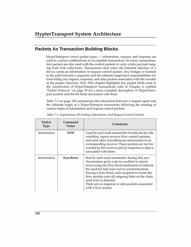
HypterTransport System Architecture
140
Packets As Transaction Building Blocks
HyperTransport control packet types — information, request, and response areused in various combinations to accomplish transactions. In many transactions,data packets are also used with the control packets to carry a data payload rang-ing from 0-64 valid bytes. Transactions start when the transmit interface of adevice sends an information or request control packet. Any bridges or tunnelsin the path between a requester and the ultimate target have responsibilities forforwarding any request, response, and data packets associated with the transferin the proper direction. Note: This chapter highlights key packet fields used inthe construction of HyperTransport transactions; refer to Chapter 4, entitled"Packet Protocol," on page 59 for a more complete description of HyperTrans-port packets and the bit fields associated with them.
Table 7-1 on page 140 summarizes the interaction between a request agent andthe ultimate target of a HyperTransport transaction following the sending ofvarious types of information and request control packets.
Table 7-1: Implications Of Sending Information And Request Control Packets
PacketType
CommandName
Comments
Information NOP Used by each node transmitter to indicate the idle condition, report receiver flow control updates, and send other miscellaneous information to its corresponding receiver. These packets are not for-warded by the receiver and no response or data is associated with them.
Information Sync/Error Sent by each node transmitter during link syn-chronization or by a device enabled to report errors using the Sync flood mechanism to indicate the need for link reset and re-synchronization. During a Sync flood, each recipient re-issues the Sync packets onto all outgoing links on the chain until reset is detected.There are no response or data packets associated with a Sync packet.
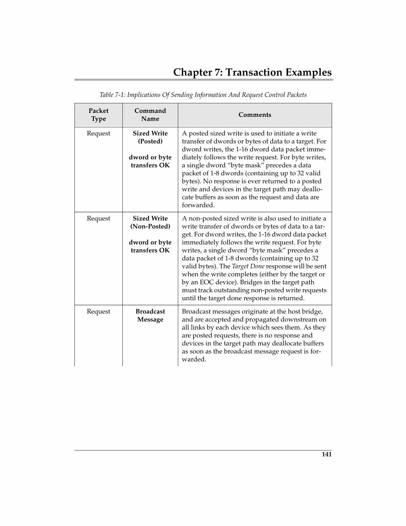
Chapter 7: Transaction Examples
141
Request Sized Write(Posted)
dword or byte transfers OK
A posted sized write is used to initiate a write transfer of dwords or bytes of data to a target. For dword writes, the 1-16 dword data packet imme-diately follows the write request. For byte writes, a single dword “byte mask” precedes a data packet of 1-8 dwords (containing up to 32 valid bytes). No response is ever returned to a posted write and devices in the target path may deallo-cate buffers as soon as the request and data are forwarded.
Request Sized Write(Non-Posted)
dword or byte transfers OK
A non-posted sized write is also used to initiate a write transfer of dwords or bytes of data to a tar-get. For dword writes, the 1-16 dword data packet immediately follows the write request. For byte writes, a single dword “byte mask” precedes a data packet of 1-8 dwords (containing up to 32 valid bytes). The Target Done response will be sent when the write completes (either by the target or by an EOC device). Bridges in the target path must track outstanding non-posted write requests until the target done response is returned.
Request BroadcastMessage
Broadcast messages originate at the host bridge, and are accepted and propagated downstream on all links by each device which sees them. As they are posted requests, there is no response and devices in the target path may deallocate buffers as soon as the broadcast message request is for-warded.
Table 7-1: Implications Of Sending Information And Request Control Packets
PacketType
CommandName
Comments
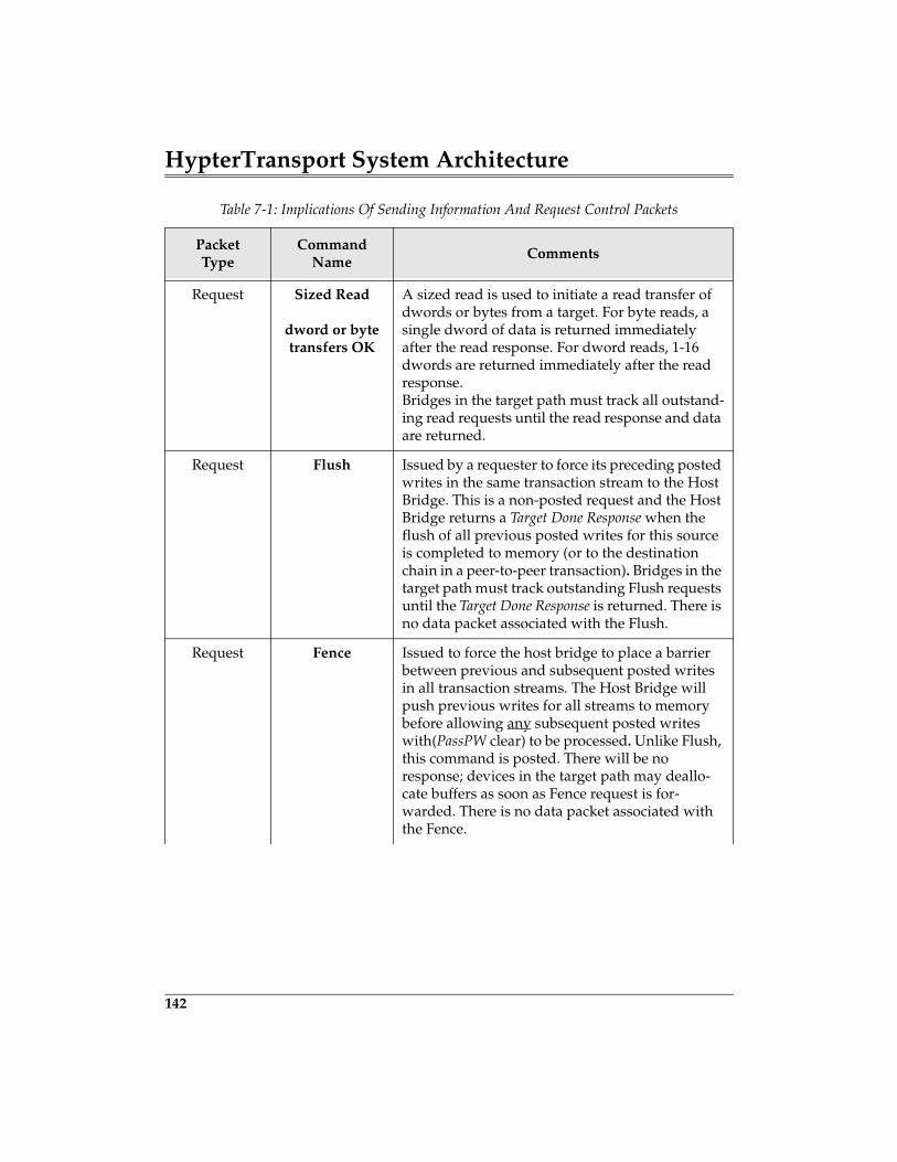
HypterTransport System Architecture
142
Request Sized Read
dword or byte transfers OK
A sized read is used to initiate a read transfer of dwords or bytes from a target. For byte reads, a single dword of data is returned immediately after the read response. For dword reads, 1-16 dwords are returned immediately after the read response.Bridges in the target path must track all outstand-ing read requests until the read response and data are returned.
Request Flush Issued by a requester to force its preceding posted writes in the same transaction stream to the Host Bridge. This is a non-posted request and the Host Bridge returns a Target Done Response when the flush of all previous posted writes for this source is completed to memory (or to the destination chain in a peer-to-peer transaction). Bridges in the target path must track outstanding Flush requests until the Target Done Response is returned. There is no data packet associated with the Flush.
Request Fence Issued to force the host bridge to place a barrier between previous and subsequent posted writes in all transaction streams. The Host Bridge will push previous writes for all streams to memory before allowing any subsequent posted writes with(PassPW clear) to be processed. Unlike Flush, this command is posted. There will be no response; devices in the target path may deallo-cate buffers as soon as Fence request is for-warded. There is no data packet associated with the Fence.
Table 7-1: Implications Of Sending Information And Request Control Packets
PacketType
CommandName
Comments
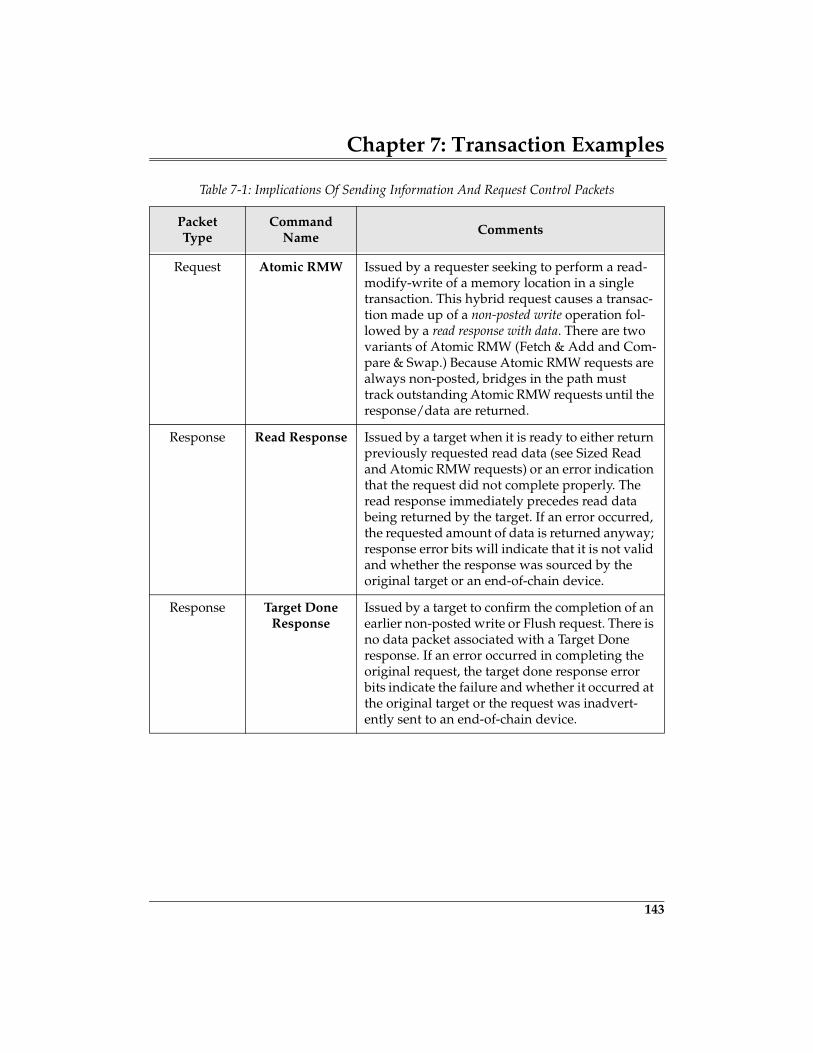
Chapter 7: Transaction Examples
143
Request Atomic RMW Issued by a requester seeking to perform a read-modify-write of a memory location in a single transaction. This hybrid request causes a transac-tion made up of a non-posted write operation fol-lowed by a read response with data. There are two variants of Atomic RMW (Fetch & Add and Com-pare & Swap.) Because Atomic RMW requests are always non-posted, bridges in the path must track outstanding Atomic RMW requests until the response/data are returned.
Response Read Response Issued by a target when it is ready to either return previously requested read data (see Sized Read and Atomic RMW requests) or an error indication that the request did not complete properly. The read response immediately precedes read data being returned by the target. If an error occurred, the requested amount of data is returned anyway; response error bits will indicate that it is not valid and whether the response was sourced by the original target or an end-of-chain device.
Response Target Done Response
Issued by a target to confirm the completion of an earlier non-posted write or Flush request. There is no data packet associated with a Target Done response. If an error occurred in completing the original request, the target done response error bits indicate the failure and whether it occurred at the original target or the request was inadvert-ently sent to an end-of-chain device.
Table 7-1: Implications Of Sending Information And Request Control Packets
PacketType
CommandName
Comments
199
8 HT Interrupts
The Previous ChapterTo review the principles of HT transactions and to provide a more comprehen-sive understanding, the previous chapter presented examples of complex sys-tem transactions, including reads, posted and non-posted writes, and atomicread-modify-write.
This ChapterHT uses an interrupt signaling scheme very similar to PCI’s Message SignaledInterrupts. This chapter defines how HT delivers interrupts to the Host Bridgevia posted memory writes. This chapter also defines an End of Interrupt mes-sage and details the mechanism that HT uses for configuring and setting upinterrupt transactions (which is different from the PCI-defined mechanisms).
The Next Chapter
Rather than requiring HT devices to incorporate additional pins for signalingsystem-related items such as power management events, System Managementmessages are defined that permit signaling via transactions, thereby creatingvirtual wires. The next chapter defines the mechanism used to send these mes-sages, by detailing the System Management packets and protocol. Some SystemManagement functions such as changing the operating frequency of an HT linkrequire that transactions be stopped. The chapter also introduces the ability totemporarily disconnect the links to allow these types of state changes, and tosave power.
Introduction
HT, unlike most legacy I/O bus implementations, does not define the use ofinterrupt pins, nor an interrupt controller. Instead, interrupt delivery is distrib-uted to the HT devices themselves. Each device delivers interrupts by perform-ing memory writes to memory address locations reserved for that purpose. Thedata written to these locations provides information that historically comes
HyperTransport System Architecture
200
from or is handled by an interrupt controller (such as interrupt priority and vec-tor information that specifies the location of the interrupt service routine). Thismethod of interrupt delivery is commonly referred to as Message SignaledInterrupts.
HT supports message signaled interrupts via two message types:
• Interrupt Request message — Interrupt requests are forwarded upstreamas sized write transactions that target a reserved interrupt request addressrange. The host bridge receives these packets and based on the targetaddress recognizes the transaction as an interrupt request. The specificactions taken by the bridge to process the interrupt request is platform-spe-cific and not specified.
• End of Interrupt message — HT also supports an End Of Interrupt (EOI)message that may be used by devices that require confirmation that theirinterrupt service routine has completed. These messages originate at thehost and are forwarded downstream as a broadcast. Like the interruptrequest message, the EOI request packet address must also fall within thereserved address range.
Discovering a Device’s Interrupt Requirements
HT defines an interrupt capability block as illustrated in Figure 8-1 on page 201.The presence of the capability block in configuration space indicates that the HTdevice uses interrupts. This block, named the Interrupt Discovery and Configu-ration Capability block, defines the number of interrupt sources each Hyper-Transport technology function can generate. This block also allows software toconfigure each interrupt independently.
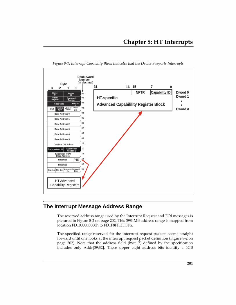
Chapter 8: HT Interrupts
201
The Interrupt Message Address Range
The reserved address range used by the Interrupt Request and EOI messages ispictured in Figure 8-2 on page 202. This 3984MB address range is mapped fromlocation FD_0000_0000h to FD_F8FF_FFFFh.
The specified range reserved for the interrupt request packets seems straightforward until one looks at the interrupt request packet definition (Figure 8-2 onpage 202). Note that the address field (byte 7) defined by the specificationincludes only Addr[39:32]. These upper eight address bits identify a 4GB
Figure 8-1: Interrupt Capability Block Indicates that the Device Supports Interrupts
Reserved
Reserved
HeaderType
Expansion ROMBase Address
Base Address 5
Base Address 0
Base Address 1
Base Address 2
Base Address 3
Base Address 4
VendorID
DeviceID
LatencyTimer
00
01
02
03
04
05
06
07
08
09
10
11
12
13
14
15
RevisionID
Class Code
InterruptLine
InterruptPinMin_GntMax_Lat
BIST CacheLineSize
StatusRegister Command
Register
DoublewordNumber
(in decimal)
0123Byte
Subsystem ID SubsystemVendor ID
CardBus CIS Pointer
PTR
Capability IDHT-specificAdvanced Capabilility Register Block
071531 16
Dword n
Dword 1Dword 0
HT AdvancedCapability Registers
NPTR
..
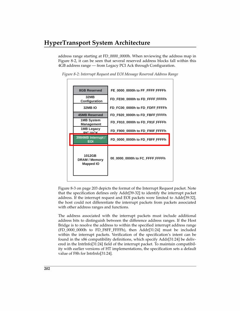
HyperTransport System Architecture
202
address range starting at FD_0000_0000h. When reviewing the address map inFigure 8-2, it can be seen that several reserved address blocks fall within this4GB address range — from Legacy PCI Ack through Configuration.
Figure 8-3 on page 203 depicts the format of the Interrupt Request packet. Notethat the specification defines only Addr[39-32] to identify the interrupt packetaddress. If the interrupt request and EOI packets were limited to Addr[39:32],the host could not differentiate the interrupt packets from packets associatedwith other address ranges and functions.
The address associated with the interrupt packets must include additionaladdress bits to distinguish between the difference address ranges. If the HostBridge is to resolve the address to within the specified interrupt address range(FD_0000_0000h to FD_F8FF_FFFFh), then Addr[31:24] must be includedwithin the interrupt packets. Verification of the specification’s intent can befound in the x86 compatibility definitions, which specify Addr[31:24] be deliv-ered in the IntrInfo[31:24] field of the interrupt packet. To maintain compatibil-ity with earlier versions of HT implementations, the specification sets a defaultvalue of F8h for IntrInfo[31:24].
Figure 8-2: Interrupt Request and EOI Message Reserved Address Range
1012GBDRAM / Memory-
Mapped IO
3984MB Interrupt /EOI
1MB LegacyPIC IACK
1MB SystemManagement
45MB Reserved
8GB Reserved
32MBConfiguration
32MB IO
00_0000_0000h to FC_FFFF_FFFFh
FD_0000_0000h to FD_F8FF_FFFFh
FD_F900_0000h to FD_F90F_FFFFh
FD_F910_0000h to FD_F91F_FFFFh
FD_F920_0000h to FD_FBFF_FFFFh
FD_FC00_0000h to FD_FDFF_FFFFh
FD_FE00_0000h to FD_FFFF_FFFFh
FE_0000_0000h to FF_FFFF_FFFFh
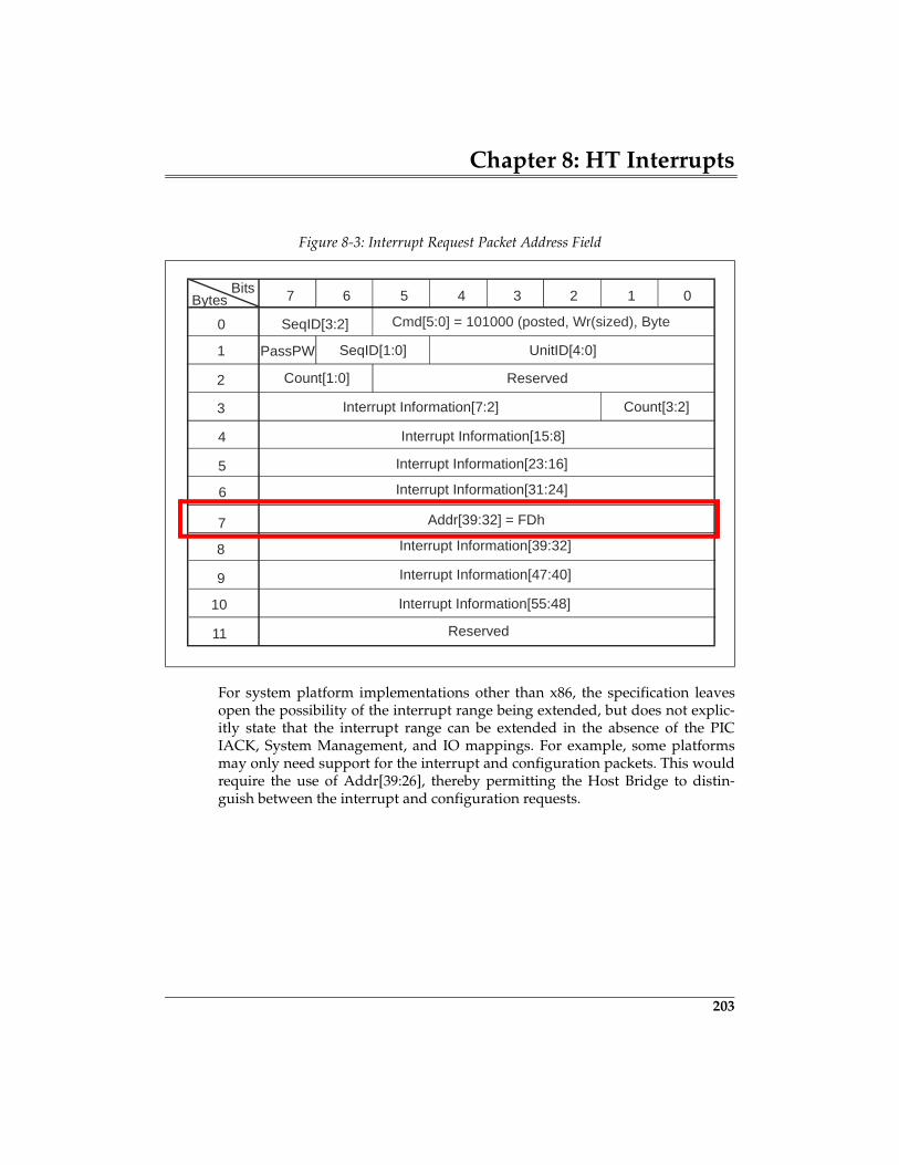
Chapter 8: HT Interrupts
203
For system platform implementations other than x86, the specification leavesopen the possibility of the interrupt range being extended, but does not explic-itly state that the interrupt range can be extended in the absence of the PICIACK, System Management, and IO mappings. For example, some platformsmay only need support for the interrupt and configuration packets. This wouldrequire the use of Addr[39:26], thereby permitting the Host Bridge to distin-guish between the interrupt and configuration requests.
Figure 8-3: Interrupt Request Packet Address Field
7 6 5 4 3 2 1 0
SeqID[3:2]0
1
2
3
4
5
6
7
SeqID[1:0] UnitID[4:0]
Count[1:0] Reserved
Interrupt Information[7:2] Count[3:2]
Interrupt Information[15:8]
Interrupt Information[31:24]
Addr[39:32] = FDh
BitsBytes
8
9
10
11
Interrupt Information[23:16]
Interrupt Information[39:32]
Interrupt Information[47:40]
Interrupt Information[55:48]
Reserved
Cmd[5:0] = 101000 (posted, Wr(sized), Byte
PassPW
215
9 System Management
The Previous ChapterHT uses an interrupt signaling scheme very similar to PCI’s Message SignaledInterrupts. The previous chapter defines how HT delivers interrupts to the HostBridge via posted memory writes. The chapter also defined an End of InterruptMessage and details the mechanism that HT uses for configuring and setting upinterrupt transactions (which is different from the PCI-defined mechanisms).
This ChapterRather than requiring HT devices to incorporate additional pins for signalingsystem-related items such as power management events, System Managementmessages are defined that permit signaling via transactions, thereby creatingvirtual wires. This chapter defines the mechanism used to send these messages,by detailing the System Management packets and protocol. Some System Man-agement functions such as changing the operating frequency of an HT linkrequire that transactions be stopped. This chapter also introduces the ability totemporarily disconnect the links to allow these types of state change and to savepower.
The Next ChapterThere are two aspects in dealing with link or internal errors in HyperTransport:detection and handling. The next chapter describes the error types defined bythe specification and what devices may do about them. Some devices maychoose to detect and handle some errors but not others. The PCI configurationspace registers, used to program the error strategy and log errors, are describedhere — as are the reporting mechanisms: error response, fatal and non-fatalinterrupts, and Sync flood.
HyperTransport System Architecture
216
System Management Transactions
HT provides a message passing mechanism between the Host Bridge and theSystem Management Controller (SMC). One of the primary purposes of HTmessages is to eliminate dedicated pins and traces that would otherwise berequired to signal various events, reducing pin count and cost. These SystemManagement (SM) messages are delivered via packets that support a wide vari-ety of functions including:
• HT Power Management• X86 Power Management• X86 Legacy CPU Signalling (e.g. A20M, FERR#, and IGNNE#)
HT System Management messages in conjunction with LDTSTOP# may be usedto support operations such as changes in operating frequency and link width, orto disable the links to save power. It is also through System Management (SM)requests that many of the x86 compatibility mechanisms are accomplished asindicated above. Further, x86 platforms are required to support SM and LDT-STOP# for power management. Power Management support for HT devices isoptional in non-x86 platforms; however, many non-x86 systems do supportpower management. Note also that the specification requires all HT devices toforward SM packets in both directions.
Sources of SM Request
System Management requests may be either sent in the upstream or down-stream direction, as illustrated in Figure 9-1 on page 217. All SM requests mov-ing upstream originate at the System Management Controller (SMC) anddownstream requests originate at the Host Bridge. Note that the SMC typicallyresides in the south bridge (or I/O Controller Hub) where the legacy signalstypically originate and where power management registers reside.
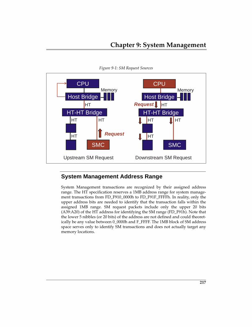
Chapter 9: System Management
217
System Management Address Range
System Management transactions are recognized by their assigned addressrange. The HT specification reserves a 1MB address range for system manage-ment transactions from FD_F910_0000h to FD_F91F_FFFFh. In reality, only theupper address bits are needed to identify that the transaction falls within theassigned 1MB range. SM request packets include only the upper 20 bits(A39:A20) of the HT address for identifying the SM range (FD_F91h). Note thatthe lower 5 nibbles (or 20 bits) of the address are not defined and could theoret-ically be any value between 0_0000h and F_FFFF. The 1MB block of SM addressspace serves only to identify SM transactions and does not actually target anymemory locations.
Figure 9-1: SM Request Sources
CPUMemory
Host Bridge
SMC
HT
HT-HT BridgeHTHT
HT Request
CPUMemory
Host Bridge
SMC
HT
HT-HT BridgeHTHT
HT
Request
Upstream SM Request Downstream SM Request
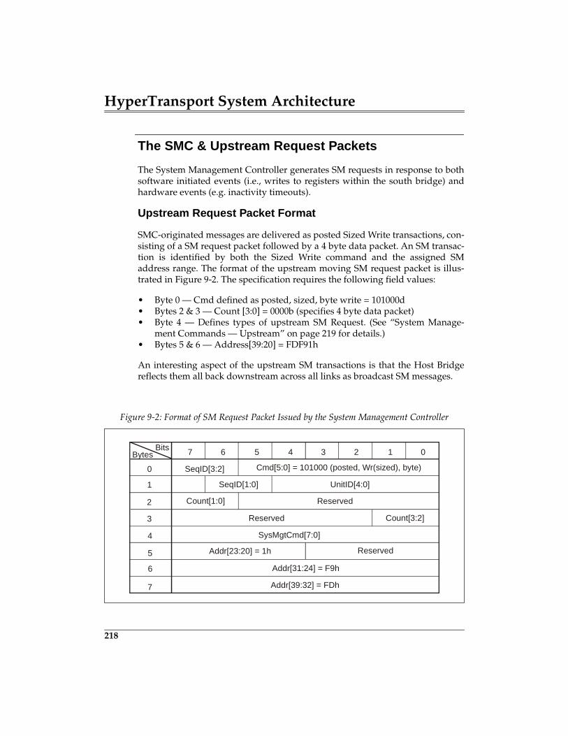
HyperTransport System Architecture
218
The SMC & Upstream Request Packets
The System Management Controller generates SM requests in response to bothsoftware initiated events (i.e., writes to registers within the south bridge) andhardware events (e.g. inactivity timeouts).
Upstream Request Packet Format
SMC-originated messages are delivered as posted Sized Write transactions, con-sisting of a SM request packet followed by a 4 byte data packet. An SM transac-tion is identified by both the Sized Write command and the assigned SMaddress range. The format of the upstream moving SM request packet is illus-trated in Figure 9-2. The specification requires the following field values:
• Byte 0 — Cmd defined as posted, sized, byte write = 101000d• Bytes 2 & 3 — Count [3:0] = 0000b (specifies 4 byte data packet)• Byte 4 — Defines types of upstream SM Request. (See “System Manage-
ment Commands — Upstream” on page 219 for details.)• Bytes 5 & 6 — Address[39:20] = FDF91h
An interesting aspect of the upstream SM transactions is that the Host Bridgereflects them all back downstream across all links as broadcast SM messages.
Figure 9-2: Format of SM Request Packet Issued by the System Management Controller
7 6 5 4 3 2 1 0
SeqID[3:2]0
1
2
3
4
5
6
7
SeqID[1:0] UnitID[4:0]
Count[1:0]
Cmd[5:0] = 101000 (posted, Wr(sized), byte)
Reserved
Reserved Count[3:2]
SysMgtCmd[7:0]
Addr[23:20] = 1h
Addr[31:24] = F9h
Addr[39:32] = FDh
BitsBytes
Reserved
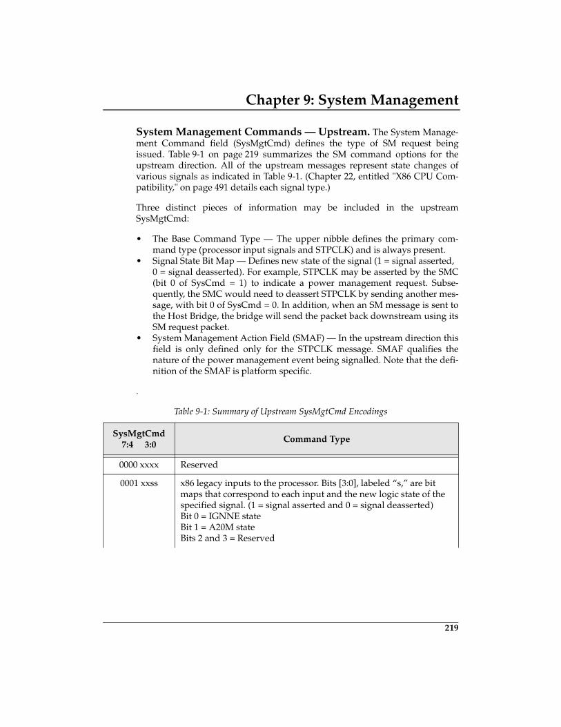
Chapter 9: System Management
219
System Management Commands — Upstream. The System Manage-ment Command field (SysMgtCmd) defines the type of SM request beingissued. Table 9-1 on page 219 summarizes the SM command options for theupstream direction. All of the upstream messages represent state changes ofvarious signals as indicated in Table 9-1. (Chapter 22, entitled "X86 CPU Com-patibility," on page 491 details each signal type.)
Three distinct pieces of information may be included in the upstreamSysMgtCmd:
• The Base Command Type — The upper nibble defines the primary com-mand type (processor input signals and STPCLK) and is always present.
• Signal State Bit Map — Defines new state of the signal (1 = signal asserted, 0 = signal deasserted). For example, STPCLK may be asserted by the SMC(bit 0 of SysCmd = 1) to indicate a power management request. Subse-quently, the SMC would need to deassert STPCLK by sending another mes-sage, with bit 0 of SysCmd = 0. In addition, when an SM message is sent tothe Host Bridge, the bridge will send the packet back downstream using itsSM request packet.
• System Management Action Field (SMAF) — In the upstream direction thisfield is only defined only for the STPCLK message. SMAF qualifies thenature of the power management event being signalled. Note that the defi-nition of the SMAF is platform specific.
.
Table 9-1: Summary of Upstream SysMgtCmd Encodings
SysMgtCmd7:4 3:0
Command Type
0000 xxxx Reserved
0001 xxss x86 legacy inputs to the processor. Bits [3:0], labeled “s,” are bit maps that correspond to each input and the new logic state of the specified signal. (1 = signal asserted and 0 = signal deasserted)Bit 0 = IGNNE stateBit 1 = A20M stateBits 2 and 3 = Reserved
229
10 Error Detection And Handling
The Previous ChapterRather than requiring HT devices to incorporate additional pins for signalingsystem-related items such as power management events, System Managementmessages are defined that permit signaling via transactions, thereby creatingvirtual wires. The previous chapter defined the mechanism used to send thesemessages, by detailing the System Management packets and protocol. SomeSystem Management functions such as changing the operating frequency of anHT link require that transactions be stopped. This chapter also introduced theability to temporarily disconnect the links to allow these types of state changeand to save power.
This ChapterAs indicated in the chapter title, there are two aspects in dealing with link orinternal errors in HyperTransport: detection and handling. This chapterdescribes the error types defined by the specification and what devices may doabout them. Some devices may choose to detect and handle some errors and notothers. The PCI configuration space registers used to program the error strategyand log errors are described here, as are the reporting mechanisms: errorresponse, fatal and non-fatal interrupts, and Sync flood.
The Next ChapterReset signalling and timing along with actions taken by the system and devicesduring reset are the primary topics discussed in the next chapter. It also dis-cusses the software initiated reset and why it’s required. The process of deter-mining the default speed and link width and the subsequent software tuning ofbus speed and link width are also detailed.
HyperTransport System Architecture
230
Introduction
HyperTransport defines six types of errors, and three basic ways they may bereported to the system.
Types Of Errors
The error types which may be detected, logged, and reported are:
1. CRC (Cycle Redundancy Code) Errors2. Protocol Errors3. Receive Buffer Overflow Errors4. End Of Chain Errors5. Chain Down Errors6. Response Errors
Reporting Methods
Once an error is detected, it can be conveyed to other devices in the system inthe following ways:
1. Error Responses2. Error Interrupts (fatal and non-fatal)3. Sync Flooding
The Role Of PCI Configuration Space
The PCI Configuration Space required of each HyperTransport device performsseveral roles in error handling. The Command and Status registers in the headerand the Link Error and Error Handling registers in the HyperTransport AdvancedCapability Register block are used to report error handling capabilities, pro-gram the error reporting mechanism to be used if an error occurs, and to log theerrors which occur so that software can later assess the error events seen byeach device.
Once the error capabilities of a device have been determined and the errorreporting strategy is programmed in configuration space, any errors whichoccur will be handled accordingly. For example, a HyperTransport device
Chapter 10: Error Detection And Handling
231
which detects a protocol error may be programmed to set the corresponding logbit in the configuration space Error Handling register and generate a fatal inter-rupt message.
Most Types Of Error Checking Are Optional
To accommodate differences in how devices and applications may view certaintypes of errors, the specification only requires CRC generation/checking oneach link; other aspects of error detection and handling are optional. If a partic-ular error is not checked, the corresponding enable and logging bits in configu-ration space must be hardwired to 0.
System Handling Of HyperTransport Errors Varies
As in many other bus protocols, HyperTransport bus behavior during errorevents is well specified but the action taken by the system in response toreported errors is implementation specific. However, if Sync flood is used as areporting mechanism, a reset is required on the affected chain(s) to restoreproper protocol.
The Error Types
The following section summarizes the required CRC generation/checking as wellas the optional protocol, receive buffer overflow, end of chain, chain down, andresponse error handling.
CRC Errors
The Cycle Redundancy Code (CRC) is used to detect transmission errors on allenabled byte lanes on each link. The 32 bit CRC value is calculated and sent atprescribed intervals by each transmitter, then checked against the CRC valuecalculated by the corresponding receiver as packets arrive. CRC is calculated byfinding the remainder when the sum of packet data (CAD bits plus CTL signalduring each bit time) is divided by the CRC polynomial. The polynomial usedis:
X32 + X26 + X23 + X22 +X16 + X12 + X11 + X10 +X8 +X7 +X5 +X4 +X2 + X +1
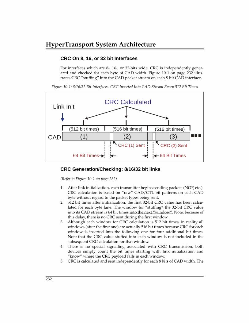
HyperTransport System Architecture
232
CRC On 8, 16, or 32 bit Interfaces
For interfaces which are 8-, 16-, or 32-bits wide, CRC is independently gener-ated and checked for each byte of CAD width. Figure 10-1 on page 232 illus-trates CRC “stuffing” into the CAD packet stream on each 8-bit CAD interface.
CRC Generation/Checking: 8/16/32 bit links
(Refer to Figure 10-1 on page 232)
1. After link initialization, each transmitter begins sending packets (NOP, etc.).CRC calculation is based on “raw” CAD/CTL bit patterns on each CADbyte without regard to the packet types being sent.
2. 512 bit times after initialization, the first 32-bit CRC value has been calcu-lated for each byte lane. The window for “stuffing” the 32-bit CRC valueinto its CAD stream is 64 bit times into the next “window”. Note: because ofthis delay, there is no CRC sent during the first window.
3. Although each window for CRC calculation is 512 bit times, in reality allwindows (after the first one) are actually 516 bit times because CRC for eachwindow is inserted into the following one for four additional bit times.Note that the CRC value stuffed into each window is not included in thesubsequent CRC calculation for that window.
4. There is no special signalling associated with CRC transmission; bothdevices simply count the bit times starting with link initialization and“know” where the CRC payload falls in each window.
5. CRC is calculated and sent independently for each 8 bits of CAD width. The
Figure 10-1: 8/16/32 Bit Interfaces: CRC Inserted Into CAD Stream Every 512 Bit Times
Link Init
CAD (2)
CRC Calculated
CRC (1) Sent
(512 bit times) (516 bit times) (516 bit times)
CRC (2) Sent
64 Bit Times 64 Bit Times
(1) (3)
Chapter 10: Error Detection And Handling
233
CTL signal itself is included in the CRC calculation for the lowest byte ofCAD (bits 0-7). On a bus wider than 8 bits, the CTL signal is also factoredinto the CRC calculation for each of the upper CAD bytes, but is assumed tobe 0 during all bit times.
6. During the driving of the CRC value itself, the CTL signal is driven = 1(Control) by the transmitter. The CRC bits are inverted before being trans-mitted onto the link.
CRC Generation/Checking: 2/4 bit links
On links narrower than 8 bits, the CRC value is generated in the same way asfor 8-bit links carrying the same value. It simply takes longer to move the pack-ets and CRC value across the link — causing the calculation window and stuff-ing point for the CRC value to be stretched accordingly. The extra assertions ofthe CTL signal (after the first bit time in each byte) are not used by the transmit-ter or receiver in the CRC calculation.
4 Bit CAD Width. A CAD width of four bits requires twice as many bittimes as an 8 bit bus for moving information across the link. Therefore:
• The CRC window size is 1024 bit times.• The CRC stuffing point starts128 bit times after the start of a window.• It takes 8 bit times to transfer the 32-bit CRC value.
2 Bit CAD Width. A CAD width of two bits requires four times as many bittimes as an eight bit bus for moving information across the link. Therefore:
• The CRC window size is 2048 bit times.• The CRC stuffing point starts 256 bit times after the start of a window.• It takes 16 bit times to transfer the 32-bit CRC value.
Logging CRC Errors
CRC errors impact both control and data information; if these errors occur onany CAD byte lane, the corresponding error bit(s) will be set in the HyperTrans-port Advanced Capability block Link Control CSR. The four bits (one for eachbyte lane) are illustrated in Figure 10-2 on page 234 below.
257
11 Routing Packets
The Previous ChapterThe previous chapter described HyperTransport flow control, used to throttle themovement of packets across each link interface. On a high-performance connec-tion such as HyperTransport, efficient management of transaction flow is nearlyas important as the raw bandwidth made possible by clock speed and data buswidth. Topics covered here include background information on bus flow controland the initialization and use of the HyperTransport virtual channel flow con-trol buffer mechanism defined for each transmitter-receiver pair.
This ChapterThis chapter describes the rules governing acceptance, forwarding, and rejec-tion of packets seen by HyperTransport devices. Several factors come into playin routing, including the packet type, the direction it is moving, and the devicetype which sees it. A related topic also covered in this chapter is the fairnessalgorithm used by a tunnel device as it inserts its own packets into the traffic itforwards upstream on behalf of devices below it. The HyperTransport specifica-tion provides a fairness algorithm and a hardware method for tunnel manage-ment packet insertion.
The Next ChapterThe next chapter describes the ordering rules which apply to packets associatedwith the three types of HyperTransport I/O traffic: PIO, DMA, and Peer-to-Peer. Depending on the whether compatibility with the full producer-consumerordering model used in PCI is required or relaxed ordering is permissible,attribute bits in request and response packets may be set or cleared. These bitsare defined by the requester and are used by devices in the path to the target,and within the target, to enforce proper ordering. HyperTransport applies dedi-cated sets of ordering rules for upstream I/O traffic, downstream I/O traffic,and the special ordering required of host bridges and in double-hosted chains.Refer to Chapter 20, entitled "I/O Compatibility," on page 457 for a description of theadditional ordering requirements when interfacing HyperTransport to other compatibleprotocols (e.g. PCI, PCI-X, and AGP).
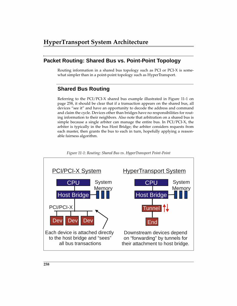
HyperTransport System Architecture
258
Packet Routing: Shared Bus vs. Point-Point Topology
Routing information in a shared bus topology such as PCI or PCI-X is some-what simpler than in a point-point topology such as HyperTransport.
Shared Bus Routing
Referring to the PCI/PCI-X shared bus example illustrated in Figure 11-1 onpage 258, it should be clear that if a transaction appears on the shared bus, alldevices “see it” and have an opportunity to decode the address and commandand claim the cycle. Devices other than bridges have no responsibilities for rout-ing information to their neighbors. Also note that arbitration on a shared bus issimple because a single arbiter can manage the entire bus. In PCI/PCI-X, thearbiter is typically in the bus Host Bridge; the arbiter considers requests fromeach master, then grants the bus to each in turn, hopefully applying a reason-able fairness algorithm.
Figure 11-1: Routing: Shared Bus vs. HyperTransport Point-Point
CPU SystemMemory
Host Bridge
Tunnel
CPU SystemMemory
Host Bridge
Dev Dev Dev
PCI/PCI-X System HyperTransport System
PCI/PCI-X
Downstream devices dependon “forwarding” by tunnels for
their attachment to host bridge.
Each device is attached directly to the host bridge and “sees”
all bus transactions
End
Chapter 11: Routing Packets
259
HyperTransport Point-Point Routing
In contrast to the shared bus approach, the HyperTransport topology distrib-utes responsibility for routing and forwarding packets among all devices, withthe exception of single-link end (cave) devices. For example, the tunnel periph-eral device in Figure 11-1 on page 258 must observe a set of rules governingacceptance, forwarding, and rejection of packets moving both upstream anddownstream. The end device in Figure 11-1 on page 258 is dependent on thetunnel to do this. Note that a benefit of a point-point bus is the elimination ofshared bus arbitration. Packet transfer is subject only to flow control on eachlink.
Review Of Packet Types And Formats
How a packet is routed depends in large part on the type of packet it is. Eachpacket in HyperTransport is a multiple of four bytes in size, and the specifica-tion divides packets into two types: control and data. All control packets con-tain a Command Type field in the first byte which identifies which type of controlpacket it is and the format of the remaining packet fields to follow. It also indi-cates whether data packets follow immediately (writes), will return later(reads), or are not required.
Control Packets
Control packets are sent across a link to initiate specific tasks; they containinformation fields used for several purposes: address decoding, virtual channeland transaction stream management, error reporting, and routing. Devices per-form routing functions by extracting information from key fields in controlpackets. Control packets are further divided into three groups: information,requests, and responses.
Information Packets: No Routing Required
Information packets include NOP and Sync/Error. These four-byte packets areused for communication between two ends of a link interface. When issued by atransmitter, they are always accepted by the corresponding receiver; they arenever forwarded to another link. This means that are no routing issues associ-ated with them. These two packet types will not be discussed further in thischapter.
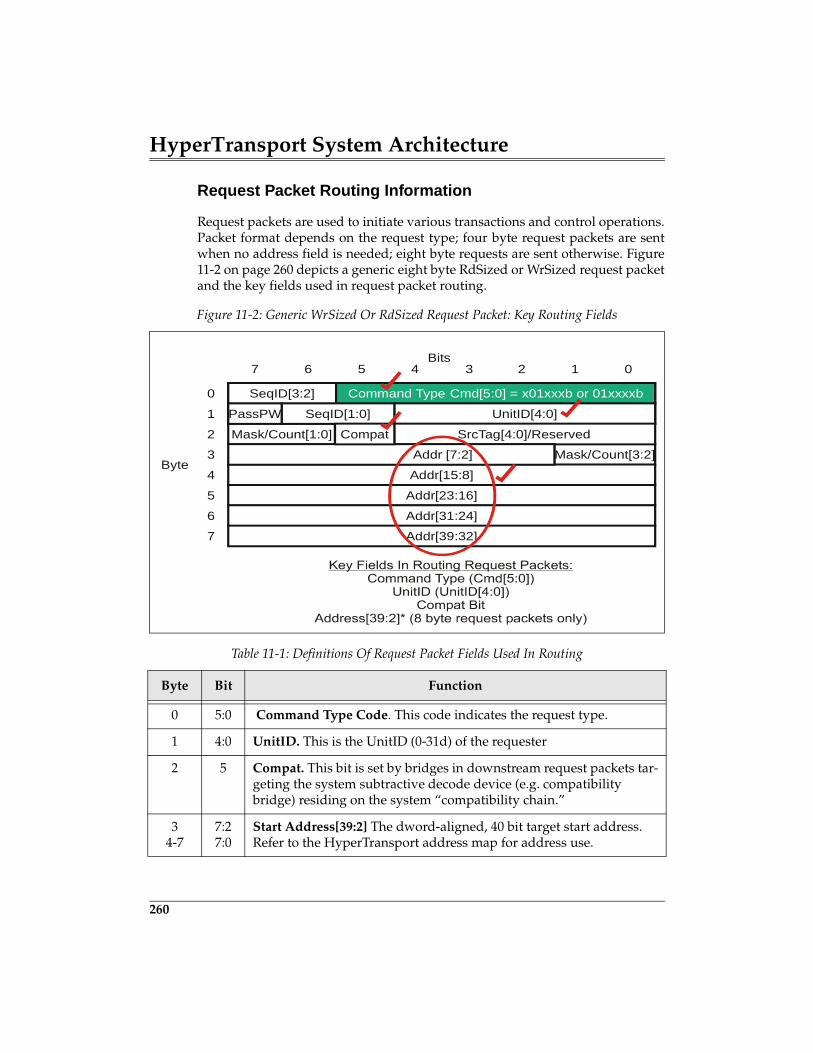
HyperTransport System Architecture
260
Request Packet Routing Information
Request packets are used to initiate various transactions and control operations.Packet format depends on the request type; four byte request packets are sentwhen no address field is needed; eight byte requests are sent otherwise. Figure11-2 on page 260 depicts a generic eight byte RdSized or WrSized request packetand the key fields used in request packet routing.
Figure 11-2: Generic WrSized Or RdSized Request Packet: Key Routing Fields
Table 11-1: Definitions Of Request Packet Fields Used In Routing
Byte Bit Function
0 5:0 Command Type Code. This code indicates the request type.
1 4:0 UnitID. This is the UnitID (0-31d) of the requester
2 5 Compat. This bit is set by bridges in downstream request packets tar-geting the system subtractive decode device (e.g. compatibility bridge) residing on the system “compatibility chain.”
34-7
7:27:0
Start Address[39:2] The dword-aligned, 40 bit target start address. Refer to the HyperTransport address map for address use.
Mask/Count[1:0]
6 5 4 3 2 17
0
Mask/Count[3:2]
Command Type Cmd[5:0] = x01xxxb or 01xxxxb
1
2
3Byte
Bits0
SeqID[3:2]
Addr[15:8]
Addr[23:16]
Addr[31:24]
Addr[39:32]
4
5
6
7
UnitID[4:0]SeqID[1:0]PassPW
SrcTag[4:0]/Reserved
Addr [7:2]
Compat
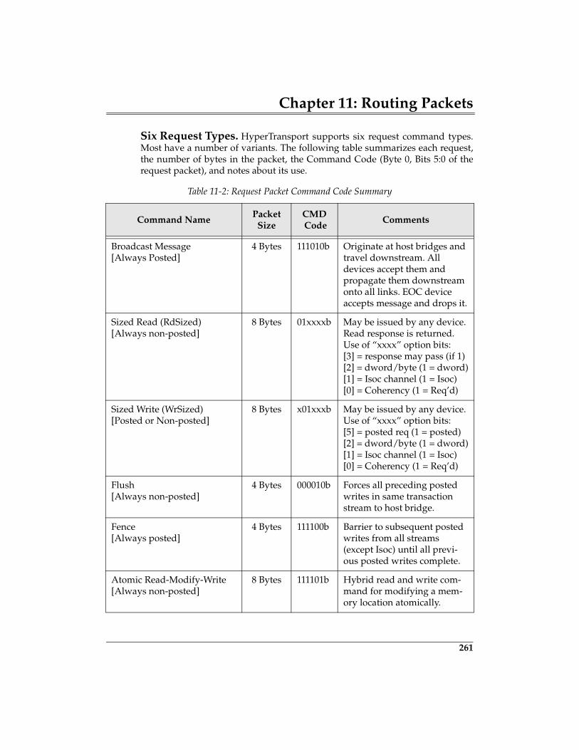
Chapter 11: Routing Packets
261
Six Request Types. HyperTransport supports six request command types.Most have a number of variants. The following table summarizes each request,the number of bytes in the packet, the Command Code (Byte 0, Bits 5:0 of therequest packet), and notes about its use.
Table 11-2: Request Packet Command Code Summary
Command NamePacket
SizeCMD Code
Comments
Broadcast Message[Always Posted]
4 Bytes 111010b Originate at host bridges and travel downstream. All devices accept them and propagate them downstream onto all links. EOC device accepts message and drops it.
Sized Read (RdSized)[Always non-posted]
8 Bytes 01xxxxb May be issued by any device. Read response is returned. Use of “xxxx” option bits:[3] = response may pass (if 1)[2] = dword/byte (1 = dword)[1] = Isoc channel (1 = Isoc)[0] = Coherency (1 = Req’d)
Sized Write (WrSized)[Posted or Non-posted]
8 Bytes x01xxxb May be issued by any device. Use of “xxxx” option bits:[5] = posted req (1 = posted)[2] = dword/byte (1 = dword)[1] = Isoc channel (1 = Isoc)[0] = Coherency (1 = Req’d)
Flush[Always non-posted]
4 Bytes 000010b Forces all preceding posted writes in same transaction stream to host bridge.
Fence[Always posted]
4 Bytes 111100b Barrier to subsequent posted writes from all streams (except Isoc) until all previ-ous posted writes complete.
Atomic Read-Modify-Write[Always non-posted]
8 Bytes 111101b Hybrid read and write com-mand for modifying a mem-ory location atomically.
275
12 Reset & Initialization
The Previous ChapterThere are two aspects in dealing with link or internal errors in HyperTransport:detection and handling. The previous chapter described all error types and dis-cussed what devices may do about them. Some devices may chose to detect andhandle some errors but not others. The PCI configuration space registers used toprogram the error strategy and log errors were described, as well as the report-ing mechanisms: error response, fatal and non-fatal interrupts, and Sync flood.
This ChapterReset signalling and timing along with actions taken by the system and devicesduring reset are the primary topics discussed in the chapter. This chapter alsodiscusses the software initiated reset and why it’s required. The process ofdetermining the default speed and link width and the subsequent software tun-ing of bus speed and link width are also detailed.
The Next ChapterHyperTransport uses PCI configuration. The next chapter describes Hyper-Transport configuration for devices other than HyperTransport-to-HyperTrans-port bridges: host bridges, tunnels, and end (I/O hub) devices.HyperTransport-to-HyperTransport bridges have a different PCI header formatthan these devices, and are described separately in the chapter on HT Bridges.Many attributes of HyperTransport configuration are exactly the same as forgeneric PCI devices, although some PCI configuration space header fields areused differently in HyperTransport, and some not at all. Devices require at leastone HyperTransport-specific advanced capability register block in addition tothe basic PCI configuration space header fields.
HyperTransport System Architecture
276
General
HyperTransport defines cold reset, warm reset, and a link initialization process.Link initialization involves determining the widest link and highest clock fre-quency that two devices attached to a link may use. Link initialization involvesa multi-step process that is initiated during cold reset.
A hardware-based handshake process determines the link width to be usedimmediately following cold reset. This process is performed by devices at bothends of every link. The handshake determines the smaller of the devicesattached to each link with respect to maximum receiver width (up to 8 bits). Forexample, one receiver may have a maximum width of 4 and the other a maxi-mum width of 8, thus the smaller CAD width (4) is used. A detailed descriptionof this process is described in the section entitled, “Low-Level Link Width Ini-tialization” on page 282. Also, following cold reset all devices use the defaultclock frequency of 200 MHz (required by all devices). The initial width negoti-ated and the default speed may be less than the actual capability of the devicesand thus require further tuning.
Next, firmware (e.g. BIOS) optimizes all links so they use the widest path andthe fastest clock that the attached devices support. This is done by reading linkcapability registers within the devices attached to each link. These registersreport the maximum link width and maximum frequency at which each deviceis designed to operate. Software determines the highest common actual CADwidth and clock frequency to be used.
Finally, firmware initiates a Warm RESET (or assertion of LDTSTOP#) to causethe new link width and clock values to take effect. Warm RESET or LDTSTOP#assertion is typically triggered by writing to an implementation-specific registerin the I/O Controller Hub.
Details regarding the process described above are discussed in the remainder ofthis chapter. Note however, that portions of the RESET initialization processthat involve clock and buffer initialization are detailed in the section called“Link Initialization” on page 282.
Cold Reset
Cold Reset is signaled during the power-up sequence under hardware control.This section details the sources, effects, and characteristics of a HyperTransportcold reset.
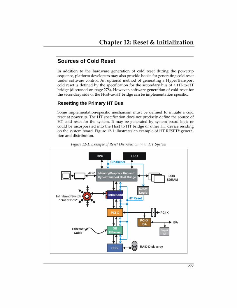
Chapter 12: Reset & Initialization
277
Sources of Cold Reset
In addition to the hardware generation of cold reset during the powerupsequence, platform developers may also provide hooks for generating cold resetunder software control. An optional method of generating a HyperTransportcold reset is defined by the specification for the secondary bus of a HT-to-HTbridge (discussed on page 278). However, software generation of cold reset forthe secondary side of the Host-to-HT bridge can be implementation specific.
Resetting the Primary HT Bus
Some implementation-specific mechanism must be defined to initiate a coldreset at powerup. The HT specification does not precisely define the source ofHT cold reset for the system. It may be generated by system board logic orcould be incorporated into the Host to HT bridge or other HT device residingon the system board. Figure 12-1 illustrates an example of HT RESET# genera-tion and distribution.
Figure 12-1: Example of Reset Distribution in an HT System
CPU CPU
Memory/Graphics Hub and HyperTransport Host Bridge
AGPDDR
SDRAM
Infiniband
PCI-X
GBEthernet
PCI-X
Infiniband Switch
SCSI RAID Disk array
PCI-XISA ISA
SuperIO
EthernetCable
“Out of Box”
Reset Logic
CPUReset
HT Reset
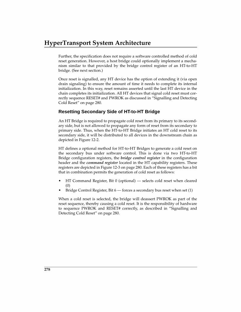
HyperTransport System Architecture
278
Further, the specification does not require a software controlled method of coldreset generation. However, a host bridge could optionally implement a mecha-nism similar to that provided by the bridge control register of an HT-to-HTbridge. (See next section.)
Once reset is signalled, any HT device has the option of extending it (via opendrain signaling) to ensure the amount of time it needs to complete its internalinitialization. In this way, reset remains asserted until the last HT device in thechain completes its initialization. All HT devices that signal cold reset must cor-rectly sequence RESET# and PWROK as discussed in “Signalling and DetectingCold Reset” on page 280.
Resetting Secondary Side of HT-to-HT Bridge
An HT Bridge is required to propagate cold reset from its primary to its second-ary side, but is not allowed to propagate any form of reset from its secondary toprimary side. Thus, when the HT-to-HT Bridge initiates an HT cold reset to itssecondary side, it will be distributed to all devices in the downstream chain asdepicted in Figure 12-2.
HT defines a optional method for HT-to-HT Bridges to generate a cold reset onthe secondary bus under software control. This is done via two HT-to-HTBridge configuration registers, the bridge control register in the configurationheader and the command register located in the HT capability registers. Theseregisters are depicted in Figure 12-3 on page 280. Each of these registers has a bitthat in combination permits the generation of cold reset as follows:
• HT Command Register, Bit 0 (optional) — selects cold reset when cleared(0)
• Bridge Control Register, Bit 6 — forces a secondary bus reset when set (1)
When a cold reset is selected, the bridge will deassert PWROK as part of thereset sequence, thereby causing a cold reset. It is the responsibility of hardwareto sequence PWROK and RESET# correctly, as described in “Signalling andDetecting Cold Reset” on page 280.
Chapter 12: Reset & Initialization
279
Figure 12-2: Example HT-to-HT Bridge Forwarding Cold Reset
CPU
HTTunnel
SCSI RAID Disk array
Reset Logic
HT Reset fromSystem Logic
(Bus N)
HT Reset (Bus N+1)
HTTunnel
CaveDevice
HT to HTBridge
305
13 Device Configuration
The Previous Chapter
Reset signalling and timing, along with actions taken by the system and devicesduring reset, are the primary topics discussed in the previous chapter. Thechapter also discussed software initiated reset and why it’s required. The pro-cess of determining the default speed and link width and the subsequent soft-ware tuning of bus speed and link width are also detailed.
This Chapter
HyperTransport uses PCI configuration. This chapter describes HyperTransporttechnology configuration for host bridges, tunnels, and end (cave) devices.These devices use the type 0 configuration header format, while HyperTrans-port-to-HyperTransport bridges and bridges between HyperTransport andother PCI compatible protocols (e.g. PCI and PCI-X) use the type 1 header for-mat and are described separately in Chapter 16, entitled "HyperTransportBridges," on page 407. Many aspects of HyperTransport device configurationare exactly the same as for generic PCI devices, although some header fields areused differently in HyperTransport, and some not at all. Devices also require atleast one HyperTransport-specific advanced capability register block in addi-tion to the basic PCI configuration space header fields.
The Next Chapter
The high speed signaling performed by HT devices is based on point-to-pointdifferential signaling and source synchronous clocking. Details associated withlink power requirements and the driver and receiver characteristics are dis-cussed in the next chapter. Also, the characteristics of the system-related signals,including RESET#, PWROK, LDTSTOP#, and LDTREQ# are discussed.
HyperTransport System Architecture
306
HyperTransport Uses PCI Configuration
Many current generation computers use the PCI configuration method and the256 byte PCI configuration space memory required of all PCI-compliant devicesto help set up and manage system chipsets and I/O peripherals. Using PCI con-figuration for a bus protocol such as HyperTransport goes a long way towardpromoting software compatibility with the millions of systems already support-ing buses employing PCI-based configuration, including PCI, AGP, PCI-X, USB,etc. HyperTransport is designed for PCI plug-and-play configuration and tominimize impact on existing BIOS and driver software.
What PCI Configuration Accomplishes
During system initialization, low level BIOS or other system software uses con-figuration transaction cycles to “walk” each PCI-compatible bus (PCI, PCI-X,HyperTransport, AGP, etc.) and read the PCI configuration space of each devicefunction it finds. Once discovered, basic and advanced capability features ofeach device are set up as appropriate. Collectively, PCI configuration cyclesmay be used for many aspects of device management, including:
• Assignment of system resources. Unlike earlier bus protocols, includingthe Industry Standard Architecture (ISA), PCI compatible plug-and-playdevices are not allowed to establish their own base addresses and interruptlevels using fixed schemes or through user manipulation of jumpers andswitches. Instead, the designer of a PCI compatible device “hard codes”information in selected PCI Configuration Space fields describing the fixedrequirements of the device with respect to memory and I/O addressesneeded, whether system interrupt support is required, arbitration needs,etc. Once the system address maps and interrupt routing are determined,software then returns to programmable fields in the PCI ConfigurationSpace of each device and programs address ranges, interrupt routing, etc.
• Enabling of device capabilities and options. In addition to assignment ofsystem resources to PCI compatible devices, software also uses the PCIConfiguration Space to select device options, enable bus mastering and tar-get decoding of memory and I/O transactions, program error responsestrategy, and set up other basic PCI and advanced capability protocol fea-tures.
• Checking of dynamic (error) status. Finally, the PCI configuration space isused to log errors resulting from attempted transactions. These loggederrors, if checked by software, provide a picture of the nature of the error,
Chapter 13: Device Configuration
307
which device(s) detected it, etc. The Status register in the configurationspace header is used for generic PCI-type error logging; in addition,advanced capability register blocks also contain logging fields for errorsrelated to a specific capability (e.g. HyperTransport CRC errors, buffer over-flow errors, etc.).
HyperTransport System Limits
HyperTransport shares PCI terminology in describing a system in terms of thenumber of buses, devices, functions, and configuration space.
256 Buses In A System
PCI permits 256 buses in a system and each PCI host bridge or PCI-to-PCIbridge secondary interface is host to a new bus with a unique bus number.Unlike PCI, a HyperTransport bus may not end with a single electrical connec-tion. Tunnel devices enable the construction of device chains which are stillviewed as a single logical bus. The 256 bus limit in HyperTransport, then, isactually 256 chains.
32 UnitIDs Per Bus
PCI permits a maximum of 32 physical devices per bus. In HyperTransport,each functional device can request multiple device numbers, called UnitIDs.The reason for this is because HyperTransport ordering rules consider the trans-actions from each UnitID to be a unique transaction stream; owning multipleUnitIDs enables a device to source more than one transaction stream (e.g. astandard transaction stream and an isochronous transaction stream for its highpriority traffic). The 32 device per bus limit in PCI is a 32 UnitID per bus limit inHyperTransport.
One To Eight Functions Per Device
As in PCI, HyperTransport allows 1-8 logical functions in a physical devicepackage. Each function has its own 256 byte configuration space, and will beassigned unique UnitID(s).
HyperTransport System Architecture
308
256 Bytes Of Configuration Space
Just as in other PCI devices, each function of a HyperTransport device mustimplement a 256 byte configuration space memory. The first one-fourth of theconfiguration space is the header. In addition to the header, devices also mustimplement at least one set of HyperTransport advanced capability registers.
Configuration Accesses: Reaching All Devices
The process of HyperTransport device configuration depends on software beingable to access the 256 byte configuration space of each function in each deviceon each bus in the system. Configuration cycles originate at the CPU that exe-cutes the configuration software; the cycles then move in the direction of the tar-get. This section compares the PCI and HyperTransport methods used to reachthe configuration space of a device which may reside on a bus many levels deepin the topology.
Implied in plug-and-play address assignment on buses such as PCI and Hyper-Transport is the fact that until it is discovered and assigned an address range bylow-level software, a device can’t claim normal memory or I/O transactions.Furthermore, whenever a bus reset occurs, each device “forgets” its addressranges and other information programmed in configuration space and can nolonger be targeted with transactions which depend on assigned addresses. So,how can a device’s configuration space be set up if it doesn’t know its targetaddress?
In addition to the problem of simple devices recognizing their own configura-tion cycles in an uninitialized system, the complex topologies permitted in PCI,PCI-X, and HyperTransport require that bridges be programmed to forwardconfiguration transactions to the proper bus before a device can even considerclaiming it.
Before looking at how HyperTransport differs from PCI in its handling of sys-tem-wide configuration accesses, here is a quick review of how PCI handlesthem.
Chapter 13: Device Configuration
309
Review: How PCI Handles Configuration Accesses
With the exception of chipsets, PCI devices generally power up (or come out ofreset) disabled with respect to either generating transactions as bus master ordecoding memory or I/O transactions as targets. This is because they are notaware of either their own plug-and-play addresses or those of other devices.The Configuration Read and Configuration Write transactions are the only ones aPCI device may decode following reset. Configuration cycles originate at theCPU, and instead of carrying conventional address information (which wouldbe useless), these cycles start downstream carrying the following attributesabout the target in the 32-bit address of the configuration read or write transac-tion:
• Bus number the target resides on (0-255 decimal)• Device number of the target (0-31 decimal)• Function number inside the target (0-7 decimal)• Double Word Offset in target’s configuration space (0-63decimal)Note that while addresses are not known after reset, bus number and device number arefunctions of the board layout and ARE known.
Two Configuration Cycle Types
As PCI configuration cycles travel downstream, there are two variants: type 0and type 1. The type is indicated in the lowest two bits of the 32-bit PCI address.Having two types is necessary because PCI devices don’t know their bus num-ber or device numbers and must depend on upstream bridges to help selectthem.
Type 1 Cycle Until Target Bus Is Reached
Starting at the host bridge, a type 1 configuration cycle is propagated down-stream until it reaches the bridge with a secondary bus number equal to that ofthe configuration cycle bus number field. Type 1 configuration cycles are ignoredby all devices except bridges which will claim them and pass them on to thenext downstream bus if the bus number field of the configuration cycle isbetween the values programmed in the bridge’s secondary and subordinate busnumber registers.
363
14 Electrical
The Previous ChapterHyperTransport uses PCI configuration. The previous chapter described Hyper-Transport technology configuration for host bridges, tunnels, and end (cave)devices. These devices use the type 0 configuration header format, while Hyper-Transport-to-HyperTransport bridges and bridges between HyperTransportand other PCI compatible protocols (e.g. PCI and PCI-X) use the type 1 headerformat and are described separately in Chapter 16, entitled "HyperTransportBridges," on page 407. Many aspects of HyperTransport device configurationare exactly the same as for generic PCI devices, although some header fields areused differently in HyperTransport, and some not at all. Devices also require atleast one HyperTransport-specific advanced capability register block in addi-tion to the basic PCI configuration space header fields.
This ChapterThe high speed signaling performed by HT devices is based on point-to-pointdifferential signaling and source synchronous clocking. Details associated withlink power requirements and the driver and receiver characteristics are dis-cussed in this chapter. Also, the characteristics of the system-related signals,including RESET#, PWROK, LDTSTOP#, and LDTREQ# are discussed.
The Next ChapterThe next chapter focuses on the source synchronous clocking environmentwithin HT. This involves the use of the source synchronous transmit clock toload data into a receive FIFO and the transfer of data into the receiver timedomain with a receive clock that unloads data from the FIFO. Additionally, thespecification defines three clocking modes that require different levels of sup-port for passing packets between these two clock domains.
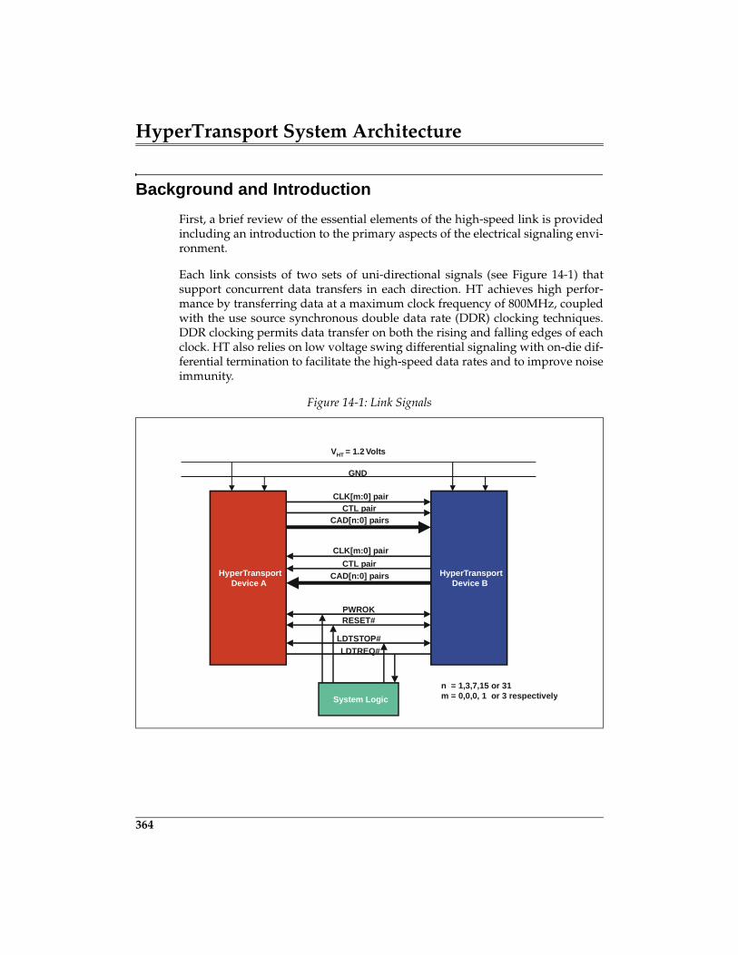
HyperTransport System Architecture
364
Background and Introduction
First, a brief review of the essential elements of the high-speed link is providedincluding an introduction to the primary aspects of the electrical signaling envi-ronment.
Each link consists of two sets of uni-directional signals (see Figure 14-1) thatsupport concurrent data transfers in each direction. HT achieves high perfor-mance by transferring data at a maximum clock frequency of 800MHz, coupledwith the use source synchronous double data rate (DDR) clocking techniques.DDR clocking permits data transfer on both the rising and falling edges of eachclock. HT also relies on low voltage swing differential signaling with on-die dif-ferential termination to facilitate the high-speed data rates and to improve noiseimmunity.
Figure 14-1: Link Signals
HyperTransportDevice A
HyperTransportDevice B
System Logic
VHT = 1.2 Volts
GND
CLK[m:0] pairCTL pair
CAD[n:0] pairs
CLK[m:0] pairCTL pair
CAD[n:0] pairs
PWROKRESET#
LDTSTOP#LDTREQ#
n = 1,3,7,15 or 31m = 0,0,0, 1 or 3 respectively
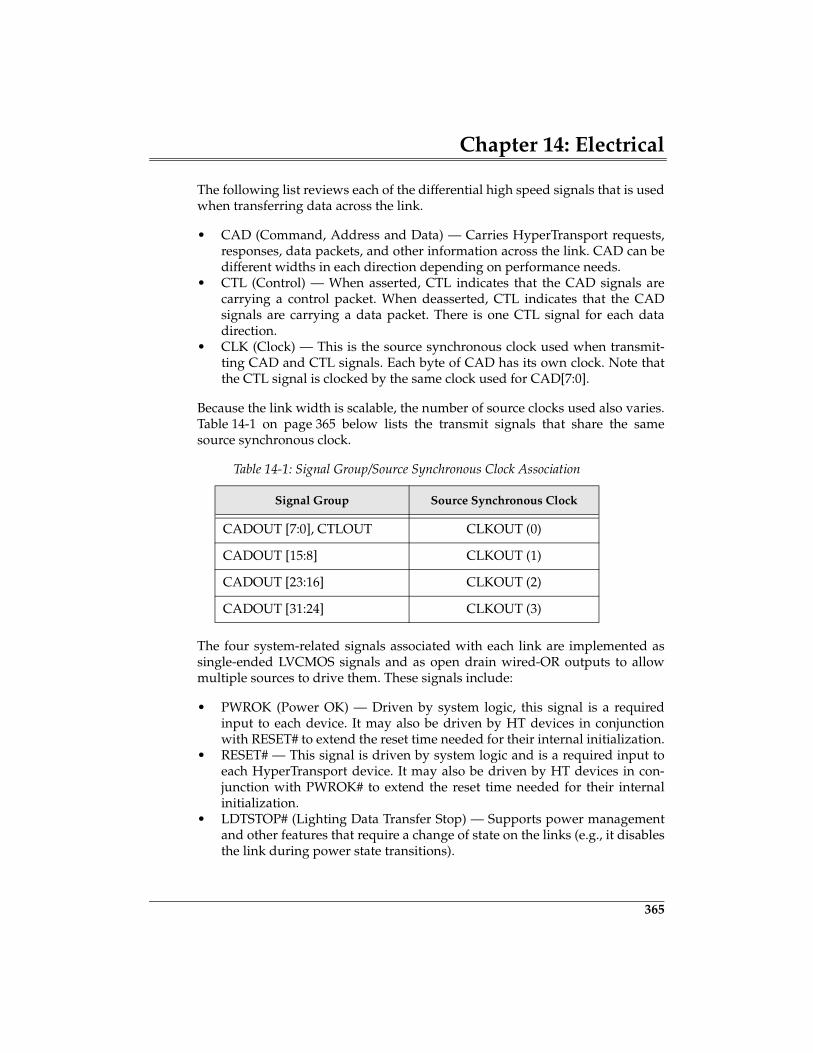
Chapter 14: Electrical
365
The following list reviews each of the differential high speed signals that is usedwhen transferring data across the link.
• CAD (Command, Address and Data) — Carries HyperTransport requests,responses, data packets, and other information across the link. CAD can bedifferent widths in each direction depending on performance needs.
• CTL (Control) — When asserted, CTL indicates that the CAD signals arecarrying a control packet. When deasserted, CTL indicates that the CADsignals are carrying a data packet. There is one CTL signal for each datadirection.
• CLK (Clock) — This is the source synchronous clock used when transmit-ting CAD and CTL signals. Each byte of CAD has its own clock. Note thatthe CTL signal is clocked by the same clock used for CAD[7:0].
Because the link width is scalable, the number of source clocks used also varies.Table 14-1 on page 365 below lists the transmit signals that share the samesource synchronous clock.
The four system-related signals associated with each link are implemented assingle-ended LVCMOS signals and as open drain wired-OR outputs to allowmultiple sources to drive them. These signals include:
• PWROK (Power OK) — Driven by system logic, this signal is a requiredinput to each device. It may also be driven by HT devices in conjunctionwith RESET# to extend the reset time needed for their internal initialization.
• RESET# — This signal is driven by system logic and is a required input toeach HyperTransport device. It may also be driven by HT devices in con-junction with PWROK# to extend the reset time needed for their internalinitialization.
• LDTSTOP# (Lighting Data Transfer Stop) — Supports power managementand other features that require a change of state on the links (e.g., it disablesthe link during power state transitions).
Table 14-1: Signal Group/Source Synchronous Clock Association
Signal Group Source Synchronous Clock
CADOUT [7:0], CTLOUT CLKOUT (0)
CADOUT [15:8] CLKOUT (1)
CADOUT [23:16] CLKOUT (2)
CADOUT [31:24] CLKOUT (3)

HyperTransport System Architecture
366
• LDTREQ# (Lightning Data Transfer Request) — An output from HTdevices that permits a device to request the links be re-enabled for normaloperation.
The following sections describe the power requirements, electrical, and timingcharacteristics of both the differential and single-ended signals, as well as anoverview of the testing environment.
Power Requirements
The HT specification defines the link supply voltage requirements and thepower consumption allowed by HT transmitters and receivers.
Power Supply Voltage
Single fixed power supply provides power to all the transmitter and receivercircuits. The HT link supply voltage (VLDT, or Voltage Lightning Data Transport) israted at:
1.2 volts ± 5%
It is possible to have tight tolerance on VLDT (+-5%) on the power supply volt-age output because most HyperTransport signals are differential with minimalcurrent transients on simultaneous switching signals. The tight tolerancerequirement on the supply voltage ensures that less power supply feedbacknoise will propagate through the system.
Differential Pair Power Consumption
The power consumption associated with the transmitter and receiver of eachdifferential signaling pair is defined by the specification. Table 14-2 on page 367lists these parameters. Note that the values are based on specified values of RONand RTT as described in the next section.
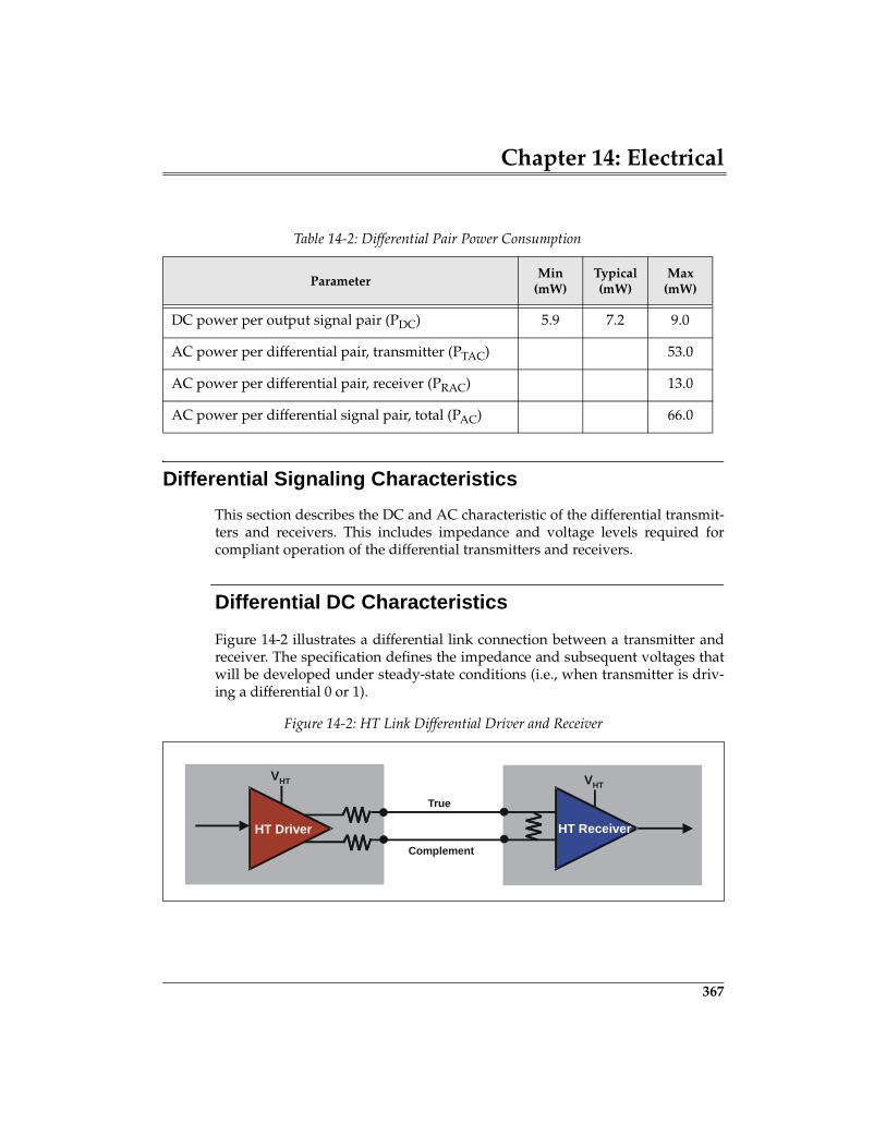
Chapter 14: Electrical
367
Differential Signaling Characteristics
This section describes the DC and AC characteristic of the differential transmit-ters and receivers. This includes impedance and voltage levels required forcompliant operation of the differential transmitters and receivers.
Differential DC Characteristics
Figure 14-2 illustrates a differential link connection between a transmitter andreceiver. The specification defines the impedance and subsequent voltages thatwill be developed under steady-state conditions (i.e., when transmitter is driv-ing a differential 0 or 1).
Table 14-2: Differential Pair Power Consumption
ParameterMin
(mW)Typical (mW)
Max (mW)
DC power per output signal pair (PDC) 5.9 7.2 9.0
AC power per differential pair, transmitter (PTAC) 53.0
AC power per differential pair, receiver (PRAC) 13.0
AC power per differential signal pair, total (PAC) 66.0
Figure 14-2: HT Link Differential Driver and Receiver
VHTVHT
HT Driver HT Receiver
True
Complement
387
15 Clocking
The Previous ChapterThe high speed signaling performed by HT devices is based on point-to-pointdifferential signaling and source synchronous clocking. Details associated withlink power requirements and the driver and receiver characteristics are dis-cussed in this chapter. Also, the characteristics of the system-related signals,including RESET#, PWROK, LDTSTOP#, and LDTREQ# are discussed.
This ChapterThis chapter focuses on the source synchronous clocking environment withinHT. This involves the use of the source synchronous transmit clock to load datainto a receive FIFO and the transfer of data into the receiver time domain with areceive clock that unloads data from the FIFO. Additionally, the specificationdefines three clocking modes that require different levels of support for passingpackets between these two clock domains.
The Next ChapterThe next chapter describes the configuration of devices which use the Hyper-Transport technology type 1 configuration header for bridges. Such devicesinclude HyperTransport-to-HyperTransport bridges and bridges to other PCIcompatible protocols (e.g. HyperTransport-to-PCI or PCI-X). In this chapter, thebasic architecture of a HyperTransport-to-HyperTransport bridge is reviewedand the configuration header fields are described. Differences in usage of bitfields by HyperTransport bridge interfaces vs. PCI bridge interfaces are empha-sized. The format of PCI compatible bridge headers is formally defined in thePCI-to-PCI Bridge Architecture Specification, Revision 1.1.
HyperTransport System Architecture
388
Introduction
The point-to-point high-speed transmission of data from transmitter to receiveracross a HT link relies on source synchronous clocking. The specification identi-fies three modes of clocking:
• Synchronous• Pseudo-Synchronous• Asynchronous
The 1.04 version of the specification states that: “Only the synchronous clockingmode is fully specified in this revision of this specification.” The specificationfurther states that the other modes will be completely specified in later versionsof the specification. All HT compliant devices are required to support the syn-chronous clocking mode. This introduction defines all three modes, and latersections in this chapter detail each mode. As you may have guessed, the sectionon the synchronous mode contains considerably more detail than the othermodes.
Clock Initialization
The receive FIFO in each device must be able to absorb timing differencesbetween the transmit and receive clocks. Data is written into the FIFO in thetransmit clock domain and read in the receive clock domain.
The design and operation of this FIFO must account for the dynamic variationsin phase between the transmit clock domain (Tx Clock Out) and the receiveclock domain (Rx Clock). The FIFO depth must be large enough to store alltransmitted data until it has been safely read into the receive clock domain. Theseparation from the write pointer to which the FIFO data is written and the readpointer from which the FIFO location is read (write-to-read separation) must belarge enough to ensure the FIFO location can be read into the receive clockdomain.
The deassertion of the incoming CTL/CAD signals across a rising CLK edge isused in the transmit clock domain within each receiver to initialize the write(load) pointer. The same deassertion CTL and CAD signals is read from theFIFO synchronous to the receive clock domain and used to initialize the read(unload) pointer. The separation between the write and read pointers is calcu-lated based on worst-case variation between the transmit and receive clocks.
Chapter 15: Clocking
389
Note also that CTL cannot be used to initialize the pointers for byte lanes otherthan 0 in a multi-byte link, because CTL only exists within the byte 0 transmitclock domain.
Synchronous Clock Mode
The specification requires that all HT devices support the synchronous clockmode. This mode is the least complicated method of transferring data fromtransmitter to receiver. Synchronous clock mode requires that the transmit clockand receive clock have the same source, and operate at the same frequency. Ifwe were to assume that the transmit clock and the receive clock alwaysremained synchronized, then a simple clocking interface could be used asdescribed in the following example.
A Conceptual Example
In this synchronous example, the transmit clock (Tx Clock) and receive clock(Rx Clock) are presumed to be in synchronization. Note, however, that sourcesynchronous clocking requires that Transmit Clock Out (Tx Clk Out) be 90°phase shifted from Tx Clock. In this example all other sources of transmit toreceive clock variation are ignored, including the expected clock drift associatedwith PLLs.
Refer to Figure 15-1 on page 390 during the following discussion. (Note thatonly one link direction is illustrated.) The transmitter delivers data synchro-nously across the link using the transmit clock. Tx Clock Out is sourced laterand lags the data by 90° (or one-half bit time), thereby centering the clock edgein the middle of the valid data interval. When the data arrives at the receiver itis clocked into the FIFO using Tx Clock Out. Note that the clocked FIFO has twoentries, which provides a separation of 1 between Tx Clock Out and Rx Clock.Data written into the FIFO during clock 1 would not be read from the FIFOusing Rx Clock until clock 2. This one entry separation (called write-to-read sep-aration) permits time for the sample to be stored prior to being read (i.e. theFIFO entry is not being written to and read from in the same clock cycle). Inshort, two FIFO entries are sufficient to provide the separation needed to ensurethat data is safely stored and transferred into the receive clock domain.
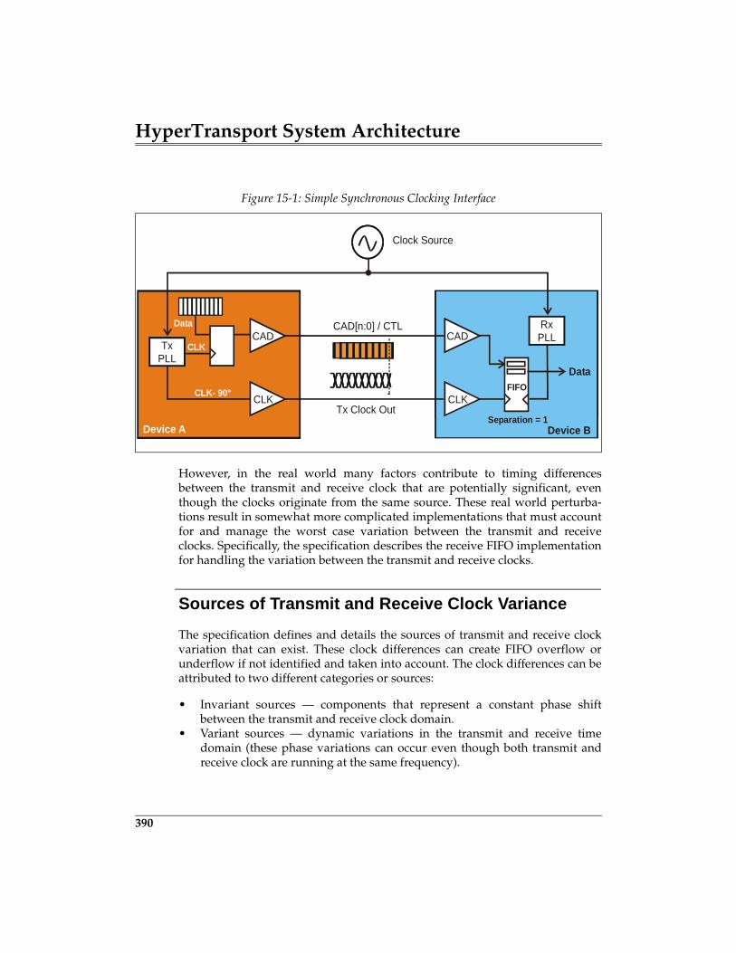
HyperTransport System Architecture
390
However, in the real world many factors contribute to timing differencesbetween the transmit and receive clock that are potentially significant, eventhough the clocks originate from the same source. These real world perturba-tions result in somewhat more complicated implementations that must accountfor and manage the worst case variation between the transmit and receiveclocks. Specifically, the specification describes the receive FIFO implementationfor handling the variation between the transmit and receive clocks.
Sources of Transmit and Receive Clock Variance
The specification defines and details the sources of transmit and receive clockvariation that can exist. These clock differences can create FIFO overflow orunderflow if not identified and taken into account. The clock differences can beattributed to two different categories or sources:
• Invariant sources — components that represent a constant phase shiftbetween the transmit and receive clock domain.
• Variant sources — dynamic variations in the transmit and receive timedomain (these phase variations can occur even though both transmit andreceive clock are running at the same frequency).
Figure 15-1: Simple Synchronous Clocking Interface
Clock Source
CAD[n:0] / CTL
Tx Clock Out
RxPLL
Device A Device B
CADData
CAD
CLK
Data
CLK- 90°
CLKTxPLL
CLKFIFO
Separation = 1
Chapter 15: Clocking
391
The sources of clock variation in some cases can accumulate over time, causingclock variation to increase over time. However, all of the sources of clock varia-tion are naturally limited in terms of the maximum amount of change that canoccur. For example, a PLL is designed to produce an output clock that is syn-chronized with the input source clock, but with certain limitations. That is, vari-ation of output frequency is specified not to change beyond a certain phaseshift. The time over which the clock phase may change can be relatively short orperhaps much longer depending upon conditions. The consideration andassessment of the sources of clock variance is done to determine a FIFO size thatcan absorb the worst-case clock variation. This would occur if all sources ofclock variation simultaneously reach their extremes, a very unlikely circum-stance.
This chapter discusses the variant and invariant sources of transmit clock toreceive clock variance. It also provides an example timing budget for eachsource.
Invariant Sources
The time-invariant factors contribute a small proportion of the overall clockvariance. The invariant factors include:
1. Cross-byte skew in multi-byte link implementations2. Sampling Error
Cross-byte skew in multi-byte link implementations. Differencesin the arrival of Tx Clock Out at the receiver (CLKIN) between each byte lane iscaused by path length mismatch. This constant skew is termed Tbytelaneconst inthe specification. The specification allows up to 1000ps for this skew. Conse-quently, when multiple bytes are clocked into the FIFO the maximum skewcould result in one of the bytes being clocked into the FIFO 1000ps later than theassociated bytes. Thus, when the associated bytes are clocked out of the FIFO byRx Clock, one byte having arrived late may be left behind. This problem issolved by adding additional entries in the FIFOs to handle the maximum lane-to-lane skew, ensuring that all associated bytes are clocked out at the same time.Note that lane-to-lane skew may change due to the effects of temperature, volt-age change, etc. This parameter called Tbytelanevar is included in the variantsource list.
407
16 HyperTransport Bridges
The Previous ChapterThe previous chapter focused on the source synchronous clocking environmentwithin HT. This involves the use of the source synchronous transmit clock toload data into a receive FIFO and the transfer of data into the receiver timedomain with a receive clock that unloads data from the FIFO. Additionally, thespecification defines three clocking modes that require different levels of sup-port for passing packets between these two clock domains.
This ChapterThis chapter describes the configuration of devices which use the HyperTrans-port technology type 1 configuration header for bridges. Such devices includeHyperTransport-to-HyperTransport bridges and bridges to other PCI compati-ble protocols (e.g. HyperTransport-to-PCI or PCI-X). In this chapter, the basicarchitecture of a HyperTransport-to-HyperTransport bridge is reviewed and theconfiguration header fields are described. Differences in usage of bit fields byHyperTransport bridge interfaces vs. PCI bridge interfaces are emphasized. Theformat of PCI compatible bridge headers is formally defined in the PCI-to-PCIBridge Architecture Specification, Revision 1.1.
The Next ChapterThe next chapter describes the features of the optional HyperTransport double-hosted chain topologies. Topics include the reasons behind sharing and non-sharing chains, PCI configuration space registers used to initialize the fabric formultiple hosts, and tunnel support for upstream and downstream packets mov-ing in both directions.
HyperTransport System Architecture
408
HyperTransport Bridges Uses PCI Configuration
HyperTransport bridges use the PCI configuration method and the 256 byteconfiguration space to set up and manage one primary bus and one or more sec-ondary buses. The primary and secondary interfaces of a HyperTransportbridge may both be HyperTransport, or either one could bridge to another PCI-compatible protocol such as PCI or PCI-X. Because the configuration headercontains bits to manage two different interfaces, there are two things to keep inmind when describing bridges between HyperTransport and another protocol:
1. For the HyperTransport interface, the meaning of some bits in the configu-ration header depends upon the particular interface (primary or secondary)that is implemented as HyperTransport.
2. For the interface that is not HyperTransport, bit field definitions revert backto the bus protocol being supported (e.g. PCI or PCI-X).
Basic Jobs Of A HyperTransport Bridge
As in the case of PCI bridges, a HyperTransport bridge has a number of respon-sibilities:
1. It extends the topology through the addition of one or more secondarybuses. Each HyperTransport chain (bus) can support up to 32 UnitIDs.Because a device is permitted to consume multiple UnitID’s, implementinga bridge is a reasonable way to add a new chain that can support 32 addi-tional UnitIDs (the bridge secondary interface consumes at least one of thenew UnitIDs).
2. It acts as host for each of its secondary chains. There are many aspects tothis, including ordering responsibilities, error handling, maintaining aqueue for outstanding transactions routed to other buses, reflecting peer-to-peer transactions originating below it, decoding memory addresses so itmay claim and forward transactions moving between the primary and sec-ondary bus, forwarding/converting configuration cycles based on targetbus number, etc.
3. In cases where it bridges between HyperTransport and PCI/PCI-X, thebridge also must translate protocols for transactions going in either directi-ion. It may also have to remap address ranges between the 40-bit Hyper-Transport address range and the 32/64-bit PCI or PCI-X range.
Chapter 16: HyperTransport Bridges
409
How Does The Bridge Manage It All?
HyperTransport bridges make use of the same HyperTransport Host/Primaryand Slave/Secondary advanced capability blocks already defined for non-bridge devices. Non-bridge HyperTransport device configuration is describedin Chapter 13, entitled "Device Configuration," on page 305. Second, they imple-ment the type 1 configuration space header common to all PCI-compatiblebridges (with the redefinition of certain bits described shortly). This is fortunatebecause:
1. HyperTransport bridges maintain software compatibility with PCI bridges.2. Bridge headers already contain two sets of control/status registers for man-
aging two independent interfaces, making support for mixed HyperTrans-port and PCI/PCI-X bridges a reasonable extension. Each set of primary/secondary bus registers is programmed (and interpreted) according towhether the specific interface is HyperTransport, PCI, or PCI-X.
Same Slave/Primary And Host/Secondary Blocks
The Slave/Primary and Host/Secondary capability blocks used in non-bridgedevices such as tunnels and end (cave) devices are also used for the Hyper-Transport interfaces of bridges. Figure 16-1 on page 410 depicts a simple Hyper-Transport-to-HyperTransport bridge with a single secondary chain. Note that abridge must implement a separate Host/Secondary interface block for each sec-ondary bus it supports.
HyperTransport Bridge Header Fields
In this section, the configuration space type 1 header format for HyperTransportbridge devices is described. For the most part, HyperTransport bridges usethese fields in the same way as PCI bridges; the differences are described here.Header fields not mentioned are used in the same way as in PCI bridges. Referto “The Type 0 Header Format” on page 322 for a description of HyperTrans-port non-bridge type 0 headers.
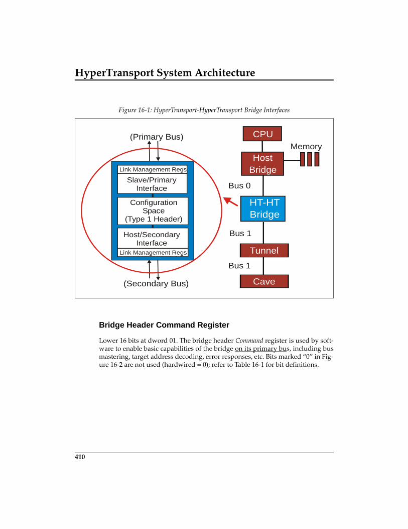
HyperTransport System Architecture
410
Bridge Header Command Register
Lower 16 bits at dword 01. The bridge header Command register is used by soft-ware to enable basic capabilities of the bridge on its primary bus, including busmastering, target address decoding, error responses, etc. Bits marked “0” in Fig-ure 16-2 are not used (hardwired = 0); refer to Table 16-1 for bit definitions.
Figure 16-1: HyperTransport-HyperTransport Bridge Interfaces
Slave/PrimaryInterface
(Primary Bus)
Host/SecondaryInterface
Link Management Regs
Link Management Regs
(Secondary Bus)
CPUMemory
Host Bridge
HT-HTBridge
TunnelBus 1
ConfigurationSpace
(Type 1 Header)
Bus 0
Cave
Bus 1
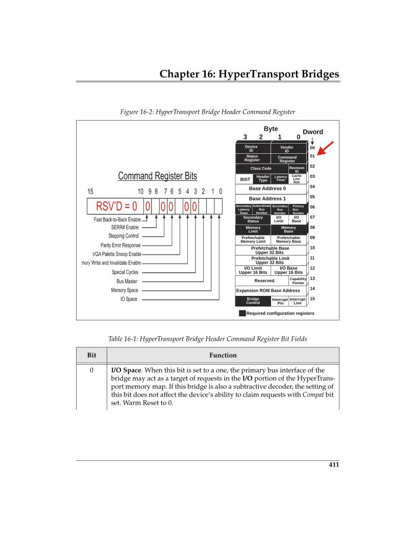
Chapter 16: HyperTransport Bridges
411
Figure 16-2: HyperTransport Bridge Header Command Register
Table 16-1: HyperTransport Bridge Header Command Register Bit Fields
Bit Function
0 I/O Space. When this bit is set to a one, the primary bus interface of the bridge may act as a target of requests in the I/O portion of the HyperTrans-port memory map. If this bridge is also a subtractive decoder, the setting of this bit does not affect the device’s ability to claim requests with Compat bit set. Warm Reset to 0.
Reserved
Prefetchable BaseUpper 32 Bits
Prefetchable LimitUpper 32 Bits
HeaderType
Expansion ROM Base Address
Base Address 0
Base Address 1
VendorID
DeviceID
LatencyTimer
00
01
02
03
04
05
06
07
08
09
10
11
12
13
14
15
RevisionID
Class Code
InterruptLine
InterruptPin
BIST
StatusRegister Command
Register
Required configuration registers
I/O BaseUpper 16 Bits
I/O LimitUpper 16 Bits
PrimaryBusNumber
SecondaryBus
Number
SubordinateBus
Number
SecondaryLatencyTimer
Secondary I/OBase
I/OLimit
MemoryBase
MemoryLimit
PrefetchableMemory Base
PrefetchableMemory Limit
SecondaryStatus
BridgeControl
CacheLineSize
0123Byte Dword
CapabilityPointer
427
17 Double-Hosted Chains
The Previous ChapterThe previous chapter described the configuration of devices that use the Hyper-Transport technology type 1 configuration header for bridges. Such devicesinclude HyperTransport-to-HyperTransport bridges and bridges to other PCIcompatible protocols (e.g. HyperTransport-to-PCI or PCI-X). The basic architec-ture of a HyperTransport-to-HyperTransport bridge is reviewed and the config-uration header fields are described. Differences in usage of bit fields byHyperTransport bridge interfaces vs. PCI bridge interfaces are emphasized. Theformat of PCI compatible bridge headers is formally defined in the PCI-to-PCIBridge Architecture Specification, Revision 1.1.
This ChapterThis chapter describes the features of the optional HyperTransport double-hosted chain topologies. Topics include the reasons behind sharing and non-sharing chains, PCI configuration space registers used to initialize the fabric formultiple hosts, and tunnel support for upstream and downstream packets mov-ing in both directions.
The Next ChapterHT provides a variety of mechanisms to support power management. Thesemechanisms include LDTSTOP#, LDTREQ#, STPCLK messages, andSTOP_GRANT messages. While these mechanism are optional for HT devices,the specification requires this support for x86-based platforms. Note also thatfunctions other than power management may make use of these signals andmessages. This chapter discusses the strategy employed by HT for implement-ing power management and how a given platform can use these mechanisms tosupport power management.
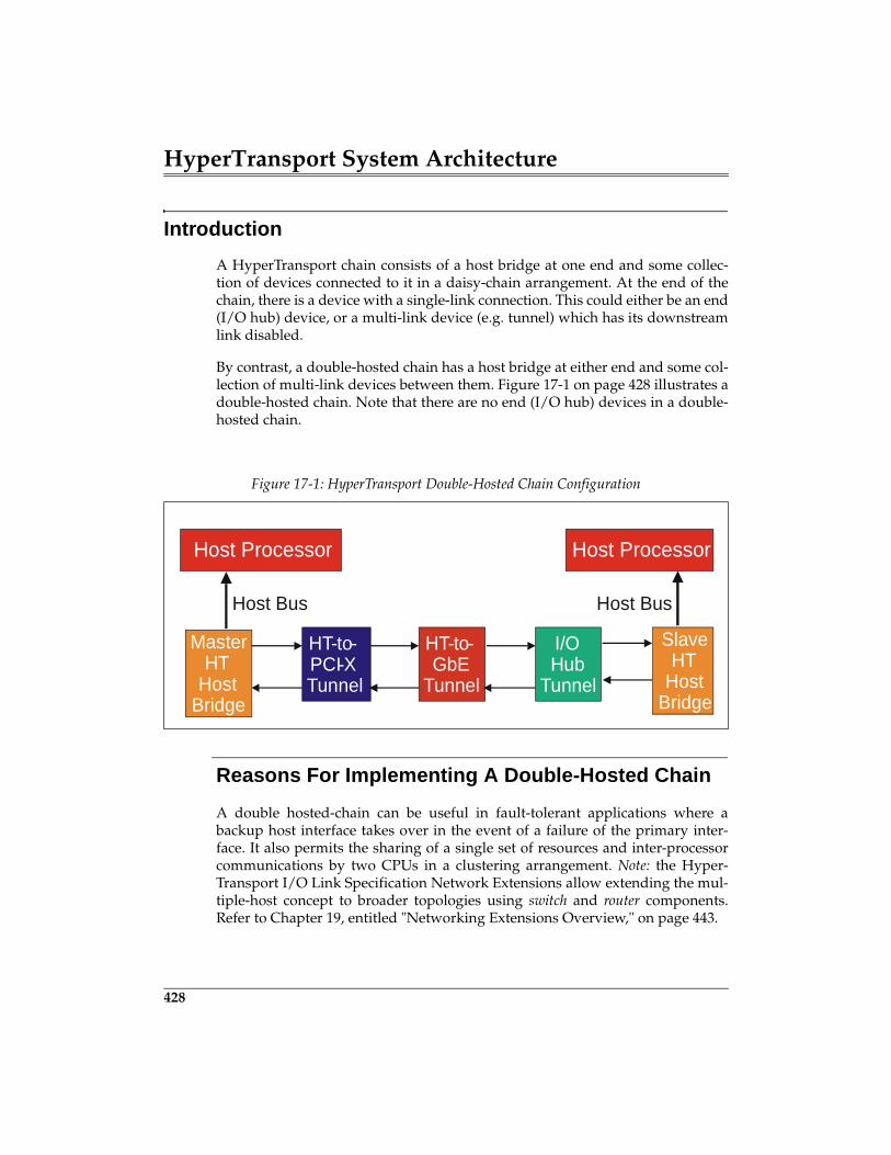
HyperTransport System Architecture
428
Introduction
A HyperTransport chain consists of a host bridge at one end and some collec-tion of devices connected to it in a daisy-chain arrangement. At the end of thechain, there is a device with a single-link connection. This could either be an end(I/O hub) device, or a multi-link device (e.g. tunnel) which has its downstreamlink disabled.
By contrast, a double-hosted chain has a host bridge at either end and some col-lection of multi-link devices between them. Figure 17-1 on page 428 illustrates adouble-hosted chain. Note that there are no end (I/O hub) devices in a double-hosted chain.
Reasons For Implementing A Double-Hosted Chain
A double hosted-chain can be useful in fault-tolerant applications where abackup host interface takes over in the event of a failure of the primary inter-face. It also permits the sharing of a single set of resources and inter-processorcommunications by two CPUs in a clustering arrangement. Note: the Hyper-Transport I/O Link Specification Network Extensions allow extending the mul-tiple-host concept to broader topologies using switch and router components.Refer to Chapter 19, entitled "Networking Extensions Overview," on page 443.
Figure 17-1: HyperTransport Double-Hosted Chain Configuration
HT-to-PCI-XTunnel
HT-to-GbE
Tunnel
I/OHub
Tunnel
SlaveHT
HostBridge
Host ProcessorHost Processor
Host Bus Host Bus
MasterHT
HostBridge
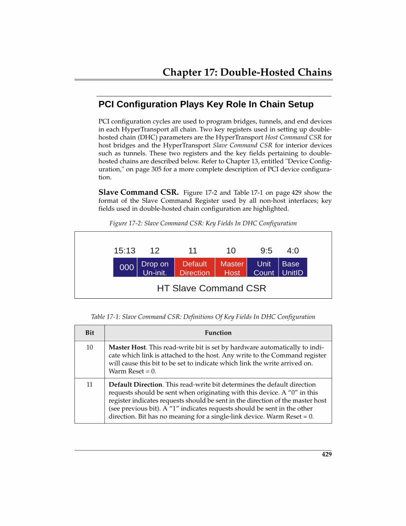
Chapter 17: Double-Hosted Chains
429
PCI Configuration Plays Key Role In Chain Setup
PCI configuration cycles are used to program bridges, tunnels, and end devicesin each HyperTransport all chain. Two key registers used in setting up double-hosted chain (DHC) parameters are the HyperTransport Host Command CSR forhost bridges and the HyperTransport Slave Command CSR for interior devicessuch as tunnels. These two registers and the key fields pertaining to double-hosted chains are described below. Refer to Chapter 13, entitled "Device Config-uration," on page 305 for a more complete description of PCI device configura-tion.
Slave Command CSR. Figure 17-2 and Table 17-1 on page 429 show theformat of the Slave Command Register used by all non-host interfaces; keyfields used in double-hosted chain configuration are highlighted.
Figure 17-2: Slave Command CSR: Key Fields In DHC Configuration
Table 17-1: Slave Command CSR: Definitions Of Key Fields In DHC Configuration
Bit Function
10 Master Host. This read-write bit is set by hardware automatically to indi-cate which link is attached to the host. Any write to the Command register will cause this bit to be set to indicate which link the write arrived on. Warm Reset = 0.
11 Default Direction. This read-write bit determines the default direction requests should be sent when originating with this device. A “0” in this register indicates requests should be sent in the direction of the master host (see previous bit). A “1” indicates requests should be sent in the other direction. Bit has no meaning for a single-link device. Warm Reset = 0.
Drop onUn-init.
DefaultDirection
MasterHost
UnitCount
BaseUnitID
15:13 12 11 10 9:5 4:0
HT Slave Command CSR
000
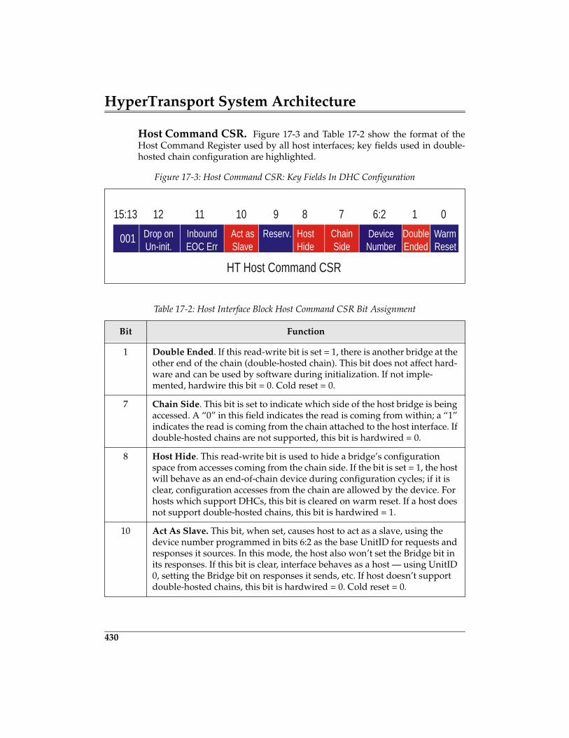
HyperTransport System Architecture
430
Host Command CSR. Figure 17-3 and Table 17-2 show the format of theHost Command Register used by all host interfaces; key fields used in double-hosted chain configuration are highlighted.
Figure 17-3: Host Command CSR: Key Fields In DHC Configuration
Table 17-2: Host Interface Block Host Command CSR Bit Assignment
Bit Function
1 Double Ended. If this read-write bit is set = 1, there is another bridge at the other end of the chain (double-hosted chain). This bit does not affect hard-ware and can be used by software during initialization. If not imple-mented, hardwire this bit = 0. Cold reset = 0.
7 Chain Side. This bit is set to indicate which side of the host bridge is being accessed. A “0” in this field indicates the read is coming from within; a “1” indicates the read is coming from the chain attached to the host interface. If double-hosted chains are not supported, this bit is hardwired = 0.
8 Host Hide. This read-write bit is used to hide a bridge’s configuration space from accesses coming from the chain side. If the bit is set = 1, the host will behave as an end-of-chain device during configuration cycles; if it is clear, configuration accesses from the chain are allowed by the device. For hosts which support DHCs, this bit is cleared on warm reset. If a host does not support double-hosted chains, this bit is hardwired = 1.
10 Act As Slave. This bit, when set, causes host to act as a slave, using the device number programmed in bits 6:2 as the base UnitID for requests and responses it sources. In this mode, the host also won’t set the Bridge bit in its responses. If this bit is clear, interface behaves as a host — using UnitID 0, setting the Bridge bit on responses it sends, etc. If host doesn’t support double-hosted chains, this bit is hardwired = 0. Cold reset = 0.
Drop onUn-init.
InboundEOC Err
Act asSlave
Reserv. HostHide
ChainSide
DeviceNumber
DoubleEnded
15:13 12 11 10 9 8 7 6:2 1 0
HT Host Command CSR
WarmReset
001
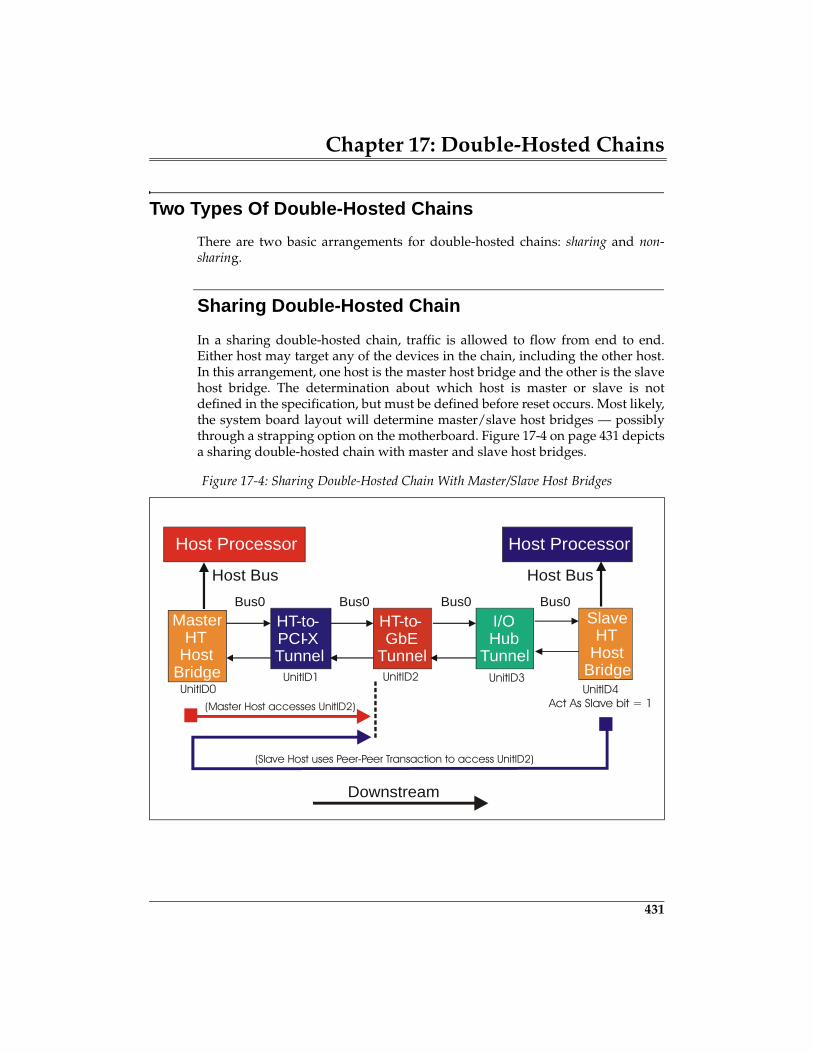
Chapter 17: Double-Hosted Chains
431
Two Types Of Double-Hosted Chains
There are two basic arrangements for double-hosted chains: sharing and non-sharing.
Sharing Double-Hosted Chain
In a sharing double-hosted chain, traffic is allowed to flow from end to end.Either host may target any of the devices in the chain, including the other host.In this arrangement, one host is the master host bridge and the other is the slavehost bridge. The determination about which host is master or slave is notdefined in the specification, but must be defined before reset occurs. Most likely,the system board layout will determine master/slave host bridges — possiblythrough a strapping option on the motherboard. Figure 17-4 on page 431 depictsa sharing double-hosted chain with master and slave host bridges.
Figure 17-4: Sharing Double-Hosted Chain With Master/Slave Host Bridges
HT-to-PCI-XTunnel
HT-to-GbE
Tunnel
I/OHub
Tunnel
SlaveHT
HostBridge
Host ProcessorHost Processor
Host Bus
Downstream
Host Bus
MasterHT
HostBridge
UnitID4Act As Slave bit = 1
UnitID3
(Slave Host uses Peer-Peer Transaction to access UnitID2)
(Master Host accesses UnitID2)
UnitID2UnitID1UnitID0
Bus0Bus0Bus0Bus0
435
18 HT Power Management
The Previous ChapterThe previous chapter described the features of the optional HyperTransportdouble-hosted chain topologies. Topics include the reasons behind sharing andnon-sharing chains, PCI configuration space registers used to initialize the fab-ric for multiple hosts, and tunnel support for upstream and downstream pack-ets moving in both directions.
This ChapterHT provides a variety of mechanisms to support power management. Thesemechanisms include LDTSTOP#, LDTREQ#, STPCLK messages, andSTOP_GRANT messages. While these mechanisms are optional for HT devices,the specification requires this support for x86-based platforms. Note also thatfunctions other than power management may make use of these signals andmessages. This chapter discusses the strategy employed by HT for implement-ing power management and how a given platform can use these mechanisms tosupport power management.
The Next ChapterThe next chapter summarizes some of the major additions to the HyperTrans-port protocol which will be forthcoming in Release 1.05 and Release 1.1 of thespecification. Collectively, these additions are referred the HyperTransport Net-working Extensions, and target some of the special requirements of communica-tions processing. Key features include a message passing protocol for largerpackets, a formal definition for switch devices, a link-level error recoverymethod, sixteen optional additional posted write virtual channels with definedarbitration and bandwidth allocation, direct peer-peer transfers, an increase inthe number of outstanding transactions for host bridges, and a 64-bit address-ing option.
HyperTransport System Architecture
436
Background
Over the years, power management control has migrated to the operating sys-tem in many platforms. System and I/O devices designers provide registers forthe OS to control power at the function, device, bus, and system levels.
• Hardware registers for power management reside in chipsets and IOdevices (e.g. PCI).
• Transitions in power state typically occur under software control as chipsethardware detects inactivity time-outs and interrupts the processor, which inturn executes the power management routines.
Some buses, such as PCI, define power management registers for each functionthat can be programmed to cause changes in power states and to enablewakeup, if supported (e.g. modem wake-up). Other buses like the ISA busappeared before power management was widely implemented, making it diffi-cult to implement power management. That is, lacking a standard set of config-uration registers, an ISA device doesn’t play well in either power managementor plug-and-play schemes. The HT specification defines the signals LDTSTOP#and LDTREQ# (LDT Request) to support power management, but does notdefine a standard set of registers for meeting low power requirements. Instead,to meet platform power management requirements, devices can gate clocks,stop PLLs, and power down portions of the device after the LDTSTOP# signal isasserted. Remote wakeup can be implemented using LDTREQ#.
In addition to LDTSTOP# and LDTREQ#, the STPCLK and STOP_GRANT mes-sages can also be used to support power management activities.
Reporting Power Management Events to the Host Bridge
HT provides two System Management messages that can be used to reportpower management events to the host.
• STPCLK message — uses the SMAF field to define the type of event beingreported and the action to be taken. The SMAF field encoding is not definedby the HT specification.
• SMI message — used to notify (interrupt) the processor when a systemmanagement event occurs. The SMI message can support power manage-ment as will as other features. (Note: SMI is an x86 legacy signal and is dis-cussed in more detail in “X86 CPU Compatibility” on page 491.)
Chapter 18: HT Power Management
437
Message transmission may be stimulated by either hardware or software. A sys-tem that supports power management will very likely include a set of registerswithin the chipset (e.g., the South bridge or ICH) to support power manage-ment. For example, a chipset may give system software the ability to selectwhich hardware events will cause the chipset to send a power managementnotification message to the Host Bridge. Similarly, software (e.g. ACPI software)may access a register, causing a power management to be sent. The actual entityresponsible for sending these message to the Host Bridge is the System Manage-ment Controller (SMC).
Reporting Host Power Management Events to SMC
The Host Bridge may also need to report power management messages to theSystem Management Controller residing on the HT bus (e.g. within the Southbridge). The mechanism for reporting such events is the STOP_GRANT mes-sage. Like the STPCLK message, the SMAF field defines the type of event beingreported and the action required.
Processor VID/FID
The specification defines a STOP_GRANT message for Voltage ID and Fre-quency ID changes associated with the processor. The Athlon processors sup-port changing the frequency and voltage used by the processor as a means ofpower conservation. That is, if the processor clock frequency is slowed, the volt-age may also be lowered for greater power conservation. When the host ini-tiates a VID/FID change, this indicates that the system is entering a low-powerstate. Consequently, the north bridge must generate a STOP_GRANT messagewith an SMAF code specifying the VID/FID change. This message results in theassertion of LDTSTOP#.
Reporting Power Management Events to HT Devices
In response to a STOP_GRANT message, the SMC controller may assert LDT-STOP to all HT device interfaces as illustrated in Figure 18-1 on page 438. Forexample, when the Host Bridge detects that the Processor is entering a VID/FIDchange, it will send a STOP_GRANT message indicating the change and caus-ing the SMC to assert LDTSTOP#. Details regarding the timing relationshipsbetween the reception of STOP_GRANT and the assertion of LDTSTOP# is dis-cussed in “The Link Initialization Disconnect Sequence” on page 227.
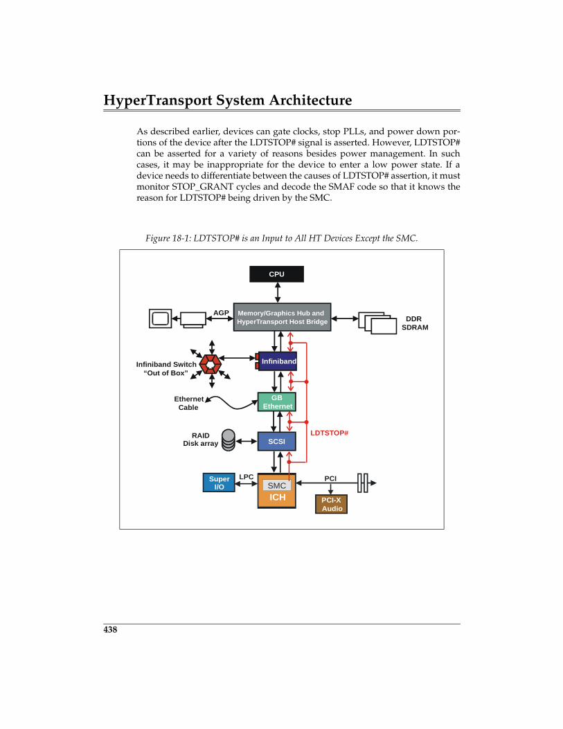
HyperTransport System Architecture
438
As described earlier, devices can gate clocks, stop PLLs, and power down por-tions of the device after the LDTSTOP# signal is asserted. However, LDTSTOP#can be asserted for a variety of reasons besides power management. In suchcases, it may be inappropriate for the device to enter a low power state. If adevice needs to differentiate between the causes of LDTSTOP# assertion, it mustmonitor STOP_GRANT cycles and decode the SMAF code so that it knows thereason for LDTSTOP# being driven by the SMC.
Figure 18-1: LDTSTOP# is an Input to All HT Devices Except the SMC.
CPU
Memory/Graphics Hub and HyperTransport Host Bridge
AGPDDR
SDRAM
Infiniband
GBEthernet
Infiniband Switch
SCSIRAID
Disk array
EthernetCable
“Out of Box”
ICH
PCI
PCI-XAudio
SuperI/O
LPCSMC
LDTSTOP#
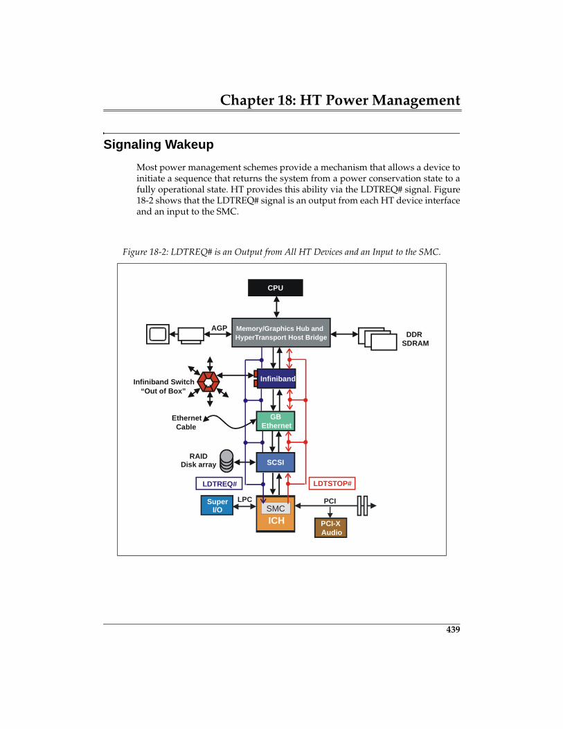
Chapter 18: HT Power Management
439
Signaling Wakeup
Most power management schemes provide a mechanism that allows a device toinitiate a sequence that returns the system from a power conservation state to afully operational state. HT provides this ability via the LDTREQ# signal. Figure18-2 shows that the LDTREQ# signal is an output from each HT device interfaceand an input to the SMC.
Figure 18-2: LDTREQ# is an Output from All HT Devices and an Input to the SMC.
CPU
Memory/Graphics Hub and HyperTransport Host Bridge
AGPDDR
SDRAM
Infiniband
GBEthernet
Infiniband Switch
SCSIRAID
Disk array
EthernetCable
“Out of Box”
ICH
PCI
PCI-XAudio
SuperI/O
LPCSMC
LDTSTOP#LDTREQ#
443
19 Networking Extensions Overview
The Previous ChapterHT provides a variety of mechanisms to support power management. Thesemechanisms include LDTSTOP#, LDTREQ#, STPCLK messages, andSTOP_GRANT messages. While these mechanism are optional for HT devices,the specification requires this support for x86-based platforms. Note also thatfunctions other than power management may make use of these signals andmessages. The previous chapter discusses the strategy employed by HT forimplementing power management and how a given platform can use thesemechanisms to support power management.
This ChapterThis chapter summarizes some of the major additions to the HyperTransportprotocol which will be forthcoming in Release 1.05 and Release 1.1 of the speci-fication. Collectively, these additions are referred the HyperTransport Network-ing Extensions, and target some of the special requirements of communicationsprocessing. Key features include a message passing protocol for larger packets,a formal definition for switch devices, a link-level error recovery method, six-teen optional additional posted write virtual channels with defined arbitrationand bandwidth allocation, direct peer-peer transfers, an increase in the numberof outstanding transactions for host bridges, and a 64-bit addressing option.
The Next ChapterHT is designed to support a variety of I/O and processor buses via bridges. Thespecification defines specific requirements for supporting PCI, PIC-X, AGP, andprocessor buses. The next chapter discusses these support requirements.
HyperTransport System Architecture
444
An Important Note
At the time of this writing, the HyperTransport I/O Link Specification Revision1.04 is released. The 1.04 revision of the specification does not deal with the net-working extensions but much of the work on the HyperTransport 1.05 and 1.1revisions has been done by the HyperTransport Technical Working Group, andquite a bit of preliminary information on this important addition to the protocolhas been released.
The networking extensions are backward compatible with the 1.04 and earlierrevisions. Compatibility extends to any mix of devices which may or may notsupport the extensions.
This chapter presents material based on information currently available. Checkhttp://www.hypertransport.org for updated information on all revisions to thespecification.
Server And Desktop Topologies Are Host-Centric
As illustrated in Figure 19-1 on page 445, a typical desktop or server platform issomewhat vertical. It has one or more processors at the top of the topology, theI/O subsystem at the bottom, and main system DRAM memory in the middleacting as a holding area for processor code and data as well as the source anddestination for I/O DMA transactions performed on behalf of the host proces-sor(s). The host processor plays the central role in both device control and inprocessing data; this is sometimes referred to as managing both the control planeand the data plane.
HyperTransport works well in this dual role because of its bandwidth and thefact that the protocol permits control information including configurationcycles, error handling events, interrupt messages, flow control, etc. to travelover the same bus as data — eliminating the need for a separate control bus oradditional sideband signals.
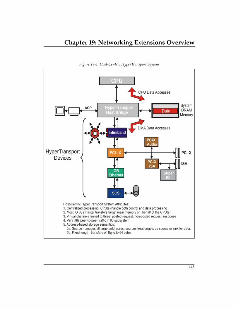
Chapter 19: Networking Extensions Overview
445
Figure 19-1: Host-Centric HyperTransport System
CPU
HyperTransport Host Bridge
AGP SystemDRAM
Memory
Infiniband
PCI - X
GBEthernet
PCI-XHyperTransportDevices
SCSI
PCI-XISA ISA
SuperIO
PCI-XAudio
DMA Data Accesses
Data
HyperTransport System Architecture
446
Upstream And Downstream Traffic
There is a strong sense of upstream and downstream data flow in server and desk-top systems because very little occurs in the system that is not under the directcontrol of the processor, acting through the host bridge. Nearly all I/O initiatedrequests move upstream and target main memory; peer-peer transactionsbetween I/O devices are the infrequent exception.
Storage Semantics In Servers And Desktops
Without the addition of networking extensions, HyperTransport protocol fol-lows the conventional model used in desktop and server busses (CPU host bus,PCI, PCI-X, etc.) in which all data transfers are associated with memoryaddresses. A write transaction is used to store a data value at an address loca-tion, and a read transaction is used to later retrieve it. This is referred to as asso-ciating storage semantics with memory addresses. The basic features of thestorage semantics model include:
Targets Are Assigned An Address Range In Memory Map
At boot time, the amount of DRAM in the system is determined and a region atthe beginning of the system address map is reserved for it. In addition, each I/Odevice conveys its resource requirements to configuration software, includingthe amount of prefetchable or non-prefetchable memory-mapped I/O addressspace it needs in the system address map. Once the requirements of all targetdevices are known, configuration software assigns the appropriate startingaddress to each device; the target device then “owns” the address rangebetween the start address and the start address plus the request size.
Each Byte Transferred Has A Unique Target Address
In storage semantics, each data packet byte is associated with a unique targetaddress. The first byte in the data packet payload maps to the start address andsuccessive data packet bytes are assumed to be in sequential addresses follow-ing the start address.
The Requester Manages Target Addresses
An important aspect of storage semantics is the fact that the requester is com-pletely responsible for managing transaction addresses within the intended tar-
Chapter 19: Networking Extensions Overview
447
get device. The target has no influence over where the data is placed duringwrite operations or retrieved in read operations.
In HyperTransport, the requester generates request packets containing the tar-get start address, then exchanges packets with the target device. The maximumpacket data payload is 64 bytes (16 dwords). Transfers larger than 64 bytes arecomprised of multiple discrete transactions, each to an adjusted start address.Using HyperTransport’s storage semantics, an ordered sequence of transactionsmay be initiated using posted writes or including a non-zero SeqID field in thenon-posted requests, but there is no concept of streaming data, per se.
Storage Semantics Work Fine In Servers And Desktops
As long as each requester is programmed to know the addresses it must target,managing address locations from the initiator side works well for general pur-pose data PIO, DMA, and peer-peer exchanges involving CPU(s), memory andI/O devices. When the target is prefetchable memory, storage semantics alsohelp support performance enhancements such as write-posting, read pre-fetch-ing, and caching — all of which depend on a requester having full control of tar-get addresses.
1.04 Protocol Optimized For Host-Centric Systems
Because the HyperTransport I/O Link Protocol was initially developed as analternative to earlier server and desktop bus protocols that use storage seman-tics (e.g. PCI), the 1.04 revision of the protocol is optimized to improve perfor-mance while maintaining backwards compatibility in host-centric systems:
1. The strongly ordered producer-consumer model used in PCI transactionswhich guarantees flag and data coherence regardless of the location of theproducer, consumer, flag location, or data storage location is available in theHyperTransport protocol.
2. Virtual channel ordering may optionally be relaxed in transfers where thefull producer-consumer model is not required.
3. The strong sense of upstream and downstream traffic on busses such as PCIis also preserved in HyperTransport. Programmed I/O (PIO) transactionsmove downstream from CPU to I/O device via the host bridge. I/O busmaster transactions move upstream towards main memory.
4. Direct peer-peer transfers are not supported in the 1.04 revision of theHyperTransport I/O Link Specification; requests targeting interior devicesmust travel up to the host bridge, then be reissued (reflected) back down-stream towards the target.
457
20 I/O Compatibility
The Previous ChapterThe previous chapter summarized some of the major additions to the Hyper-Transport protocol which will be forthcoming in Release 1.05 and Release 1.1 ofthe specification. Collectively, these additions are referred the HyperTransportNetworking Extensions, and target some of the special requirements of communi-cations processing. Key features include a message passing protocol for largerpackets, a formal definition for switch devices, a link-level error recoverymethod, sixteen optional additional posted write virtual channels with definedarbitration and bandwidth allocation, direct peer-peer transfers, an increase inthe number of outstanding transactions for host bridges, and a 64-bit address-ing option.
This ChapterHT is designed to support a variety of I/O and processor buses via bridges. Thespecification defines specific requirements for supporting PCI, PIC-X, AGP, andprocessor buses. This chapter discusses these support requirements.
The Next ChapterThe large 1 Terabyte HT address space may be outside the limits of a given pro-cessor or expansion bus. When address locations are mapped into the HT spacethat exceed the processor or expansion bus address space then the addressesmust be remapped to/from HT space. The next chapter discusses the HT solu-tion for remapping prefetchable memory, MMIO, and I/O addresses.
Introduction
PC compatibility remains important in many operating environments and mayinclude the use of several legacy buses. HT is intended to support connectionsto a variety of I/O buses, and the specification gives special attention to the PClegacy buses to ensure compatible support.
HyperTransport System Architecture
458
Several areas must be considered to ensure compatibility with I/O buses,including:
• Protocol differences• Ordering requirements• Command translation• Address space and range differences• Potential deadlocks
The buses currently supported and discussed by the HT specification includePCI, PCI-X, AGP, and host processor buses, with special attention given toissues associated with PC legacy support via the ISA/LPC buses.
PCI Bus Issues
Several features of the PCI bus must be handled in the correct fashion wheninterfacing with the HT bus. For background information and details regardingPCI ordering, refer to MindShare’s PCI System Architecture book, 4th edition.
PCI Ordering Requirements
Transaction ordering on the PCI bus is based on the Producer/Consumer pro-gramming model. This model involves 5 elements:
1. Producer — PCI master that sources data to a memory target2. Target — main memory or any PCI device containing memory3. Consumer — PCI master that reads and processes the Producer data from
the target4. Flag element — a memory or I/O location updated by the producer to indi-
cate that all data has been delivered to the target, and checked by the Con-sumer to determine when it can begin to read and process the data.
5. Status element — a memory or I/O location updated by the Consumer toindicate that it has processed all of the Producer data, and checked by theProducer to determine when the next batch of data can be sent.
This model works flawlessly in PCI when all elements reside on the sameshared PCI bus. When these elements reside on different PCI buses (i.e. acrossPCI to PCI bridges, the model can fail without adherence to the PCI orderingrules.
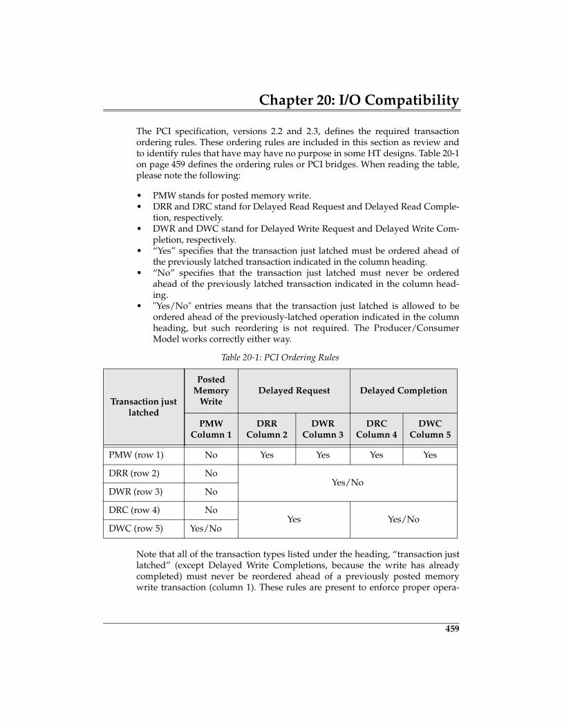
Chapter 20: I/O Compatibility
459
The PCI specification, versions 2.2 and 2.3, defines the required transactionordering rules. These ordering rules are included in this section as review andto identify rules that have may have no purpose in some HT designs. Table 20-1on page 459 defines the ordering rules or PCI bridges. When reading the table,please note the following:
• PMW stands for posted memory write.• DRR and DRC stand for Delayed Read Request and Delayed Read Comple-
tion, respectively.• DWR and DWC stand for Delayed Write Request and Delayed Write Com-
pletion, respectively.• “Yes” specifies that the transaction just latched must be ordered ahead of
the previously latched transaction indicated in the column heading.• “No” specifies that the transaction just latched must never be ordered
ahead of the previously latched transaction indicated in the column head-ing.
• "Yes/No" entries means that the transaction just latched is allowed to beordered ahead of the previously-latched operation indicated in the columnheading, but such reordering is not required. The Producer/ConsumerModel works correctly either way.
Note that all of the transaction types listed under the heading, “transaction justlatched” (except Delayed Write Completions, because the write has alreadycompleted) must never be reordered ahead of a previously posted memorywrite transaction (column 1). These rules are present to enforce proper opera-
Table 20-1: PCI Ordering Rules
Transaction just latched
Posted Memory
WriteDelayed Request Delayed Completion
PMWColumn 1
DRRColumn 2
DWRColumn 3
DRCColumn 4
DWC Column 5
PMW (row 1) No Yes Yes Yes Yes
DRR (row 2) NoYes/No
DWR (row 3) No
DRC (row 4) NoYes Yes/No
DWC (row 5) Yes/No
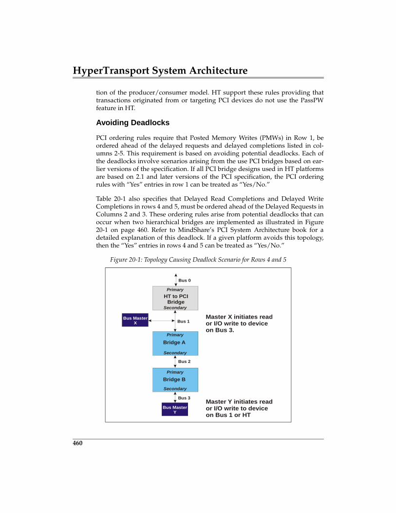
HyperTransport System Architecture
460
tion of the producer/consumer model. HT support these rules providing thattransactions originated from or targeting PCI devices do not use the PassPWfeature in HT.
Avoiding Deadlocks
PCI ordering rules require that Posted Memory Writes (PMWs) in Row 1, beordered ahead of the delayed requests and delayed completions listed in col-umns 2-5. This requirement is based on avoiding potential deadlocks. Each ofthe deadlocks involve scenarios arising from the use PCI bridges based on ear-lier versions of the specification. If all PCI bridge designs used in HT platformsare based on 2.1 and later versions of the PCI specification, the PCI orderingrules with “Yes” entries in row 1 can be treated as “Yes/No.”
Table 20-1 also specifies that Delayed Read Completions and Delayed WriteCompletions in rows 4 and 5, must be ordered ahead of the Delayed Requests inColumns 2 and 3. These ordering rules arise from potential deadlocks that canoccur when two hierarchical bridges are implemented as illustrated in Figure20-1 on page 460. Refer to MindShare’s PCI System Architecture book for adetailed explanation of this deadlock. If a given platform avoids this topology,then the “Yes” entries in rows 4 and 5 can be treated as “Yes/No.”
Figure 20-1: Topology Causing Deadlock Scenario for Rows 4 and 5
Bridge A
Bridge B
Secondary
Secondary
Primary
Primary
Bus 1
Bus 2
Bus 3
Bus MasterY
Bus MasterX
HT to PCIBridge
Secondary
Primary
Bus 0
Master X initiates reador I/O write to deviceon Bus 3.
Master Y initiates reador I/O write to deviceon Bus 1 or HT
Chapter 20: I/O Compatibility
461
Subtractive Decode
PCI employs a technique referred to as subtractive decode to handle devicesthat are mapped into memory or I/O address space by user selection ofswitches and jumpers (e.g. ISA devices). Consequently, configuration softwarehas no knowledge of the resources assigned to these devices. Fortunately, thesePC legacy devices are mapped into relatively small ranges of address space thatcan be reserved by platform configuration software.
Subtractive Decode: The PCI Method
Subtractive decode is a process of elimination. Since configuration softwareallocates and assigns address space for PCI, HT, AGP and other devices, anyaccess to address locations not assigned can be presumed to target a legacydevice, or may be an errant address.
All PCI devices must perform a positive decode to determine if they are beingtargeted by the current request. This decode must be performed as a fast,medium, or slow decode. The device targeted must indicate that it will respondto the request by signaling device select (DEVSEL#) across the shared bus.When device driver software issues a request with an address that has not beenassigned by configuration software, no PCI device is targeted (i.e. no DEVSEL#is asserted within the time allowed) By process of elimination, the subtractivedecode agent recognizes that no PCI device has responded and therefore itasserts DEVSEL# and forwards the transaction to the ISA bus, where therequest is completed.
Subtractive Decode: The Simple HT Method
An HT system with a single chain can possibly implement subtractive decodewithout extra host support required of more complex HT systems. Figure 20-2on page 462 illustrates a simple system with a single-hosted chain. Note that thesubtractive decode agent is at the end of the chain. If a request initiated at thehost reaches the South Bridge, then the bridge knows that no other HT agentshave claimed the transaction based on positive decode; therefore, a subtractivedecode is safe.
477
21 Address Remapping
The Previous ChapterHT is designed to support a variety of I/O and processor buses via bridges. Thespecification defines specific requirements for supporting PCI, PIC-X, AGP, andprocessor buses. The previous chapter discussed these support requirements.
This ChapterThe large 1 Terabyte HT address space may be outside the limits of a given pro-cessor or expansion bus. When address locations are mapped into the HT spacethat exceed the processor or expansion bus address space, then the addressesmust be remapped to and from HT space. This chapter discusses the HT solu-tion for remapping memory, MMIO, and I/O addresses.
The Next ChapterMany HT platforms may be based on x86 processors. Compatibility support forthese processors is defined by the HT specification. This chapter discusses thex86 features that require specific support by HT technology and details the HTmethods of signaling.
Introduction
An HT-based system may include processors or expansion buses that havesmaller address ranges than the large 1 TeraByte space used by HT. In suchcases address translation may be required. For example, the x86 CPU mighthave a maximum memory address range of 64GB and a PCI bus implementa-tion may be limited to 4GB of memory address space. If addresses are allocatedin HT address space beyond the range of the CPU and Expansion bus, thenaddress translation is required.
HyperTransport System Architecture
478
To illustrate the possible remapping requirement, Figure 21-1 on page 479depicts an implementation similar to that described in the previous paragraph.This example does not depict a typical implementation, but rather illustrates anextreme case where address remapping is required by both the CPU to HTBridge and the HT-to-PCI Bridge. The system allocates a 4GB range of processormemory address space for PCI devices that is near the top of the 64GB range.This processor address space is mapped into the HT space above the 64GBrange of the processor and beyond the address range of the PCI bus. When soft-ware executing on the CPU accesses a memory location within a PCI device twoaddress translations must occur:
1. The CPU to HT Bridge must translate the CPU address within the 60 - 64GBaddress range to the 1,008 to 1,012GB range.
2. The HT-to-PCI Bridge must translate the HT address down to the 0-4GBrange of the PCI bus.
A similar address translation must take place to support I/O address space. HTmaps I/O space very high in its address space and outside the range of both theCPU and PCI bus, thereby creating the need for address remapping.
HT provides an Address Remapping Capability Block that support remappingHT addresses to expansion buses. However, the specification does not define amechanism for remapping CPU to HT address space.
The Address Remapping Capability Block
This capability block allows software to control the HT to expansion bus bridgeaddress for:
• remapping HT I/O address space down to a lower range within an expan-sion bus.
• remapping HT MMIO space to expansion bus address space.• remapping HT Memory space to expansion bus address space.• remapping Bus Master memory transactions from expansion bus address
space to HT address space.
Figure 21-2 on page 479 illustrates the format of the Address Remapping capa-bility block. The following sections describe each register and its remappingfunction.
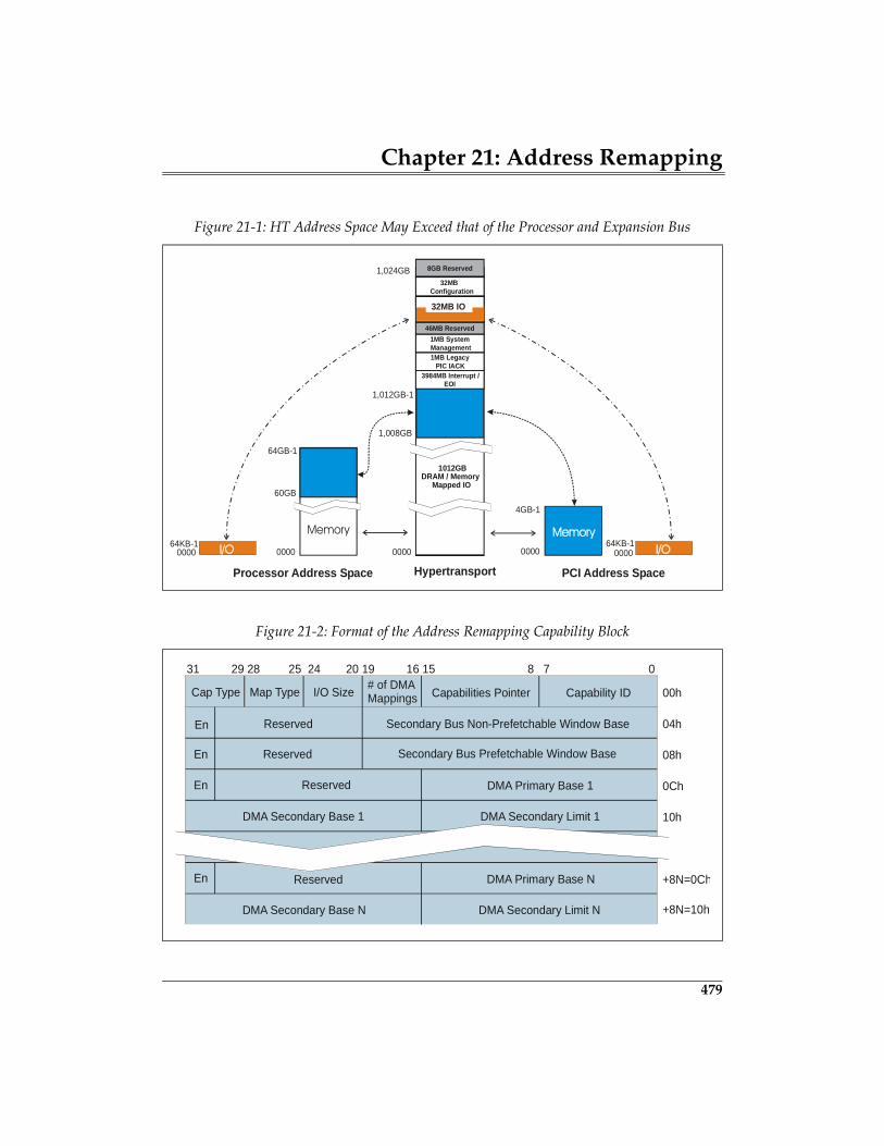
Chapter 21: Address Remapping
479
Figure 21-1: HT Address Space May Exceed that of the Processor and Expansion Bus
Figure 21-2: Format of the Address Remapping Capability Block
1012GBDRAM / Memory
Mapped IO
3984MB Interrupt /EOI
1MB LegacyPIC IACK
1MB SystemManagement
46MB Reserved
8GB Reserved
32MBConfiguration
64GB-1
0000
1,012GB-1
1,024GB
0000
4GB-1
0000
Processor Address Space Hypertransport
64KB-1Memory
64KB-1
PCI Address Space
32MB IO
1,008GB
60GB
0000 0000
Reserved
10h
# of DMAMappings Capabilities Pointer Capability ID
31 29 28 25 24 20 19 16 15 8 7 0
00h
04h
08h
0Ch
+8N=0Ch
I/O SizeMap TypeCap Type
Secondary Bus Non-Prefetchable Window Base
Secondary Bus Prefetchable Window BaseReserved
Reserved
Reserved
En
En
En
En
DMA Primary Base 1
DMA Primary Base N
DMA Secondary Limit 1
DMA Secondary Limit N
DMA Secondary Base 1
DMA Secondary Base N +8N=10h
HyperTransport System Architecture
480
The registers within the remapping capability block are briefly described below.Detailed discussion of their implementation is discussed in the following sec-tions.
• Number of DMA Mappings — This read-only field indicates how manyDMA Primary/Secondary register sets (if any) are defined by the remap-ping capability block.
• I/O Size — This register is intended to permit configuration software tolimit the I/O address range supported by the expansion bus to a rangesmaller than the 32MBs supported by HT.
• Mapping Type — The HT specification does not currently define a map-ping type. This read-only register must be zero (0) and is reserved for futureextensions.
• Capability Type — A read-only value of 01000b indicates an addressremapping capability block.
• Secondary Bus Non-Prefetchable Window Base — This register is writtenby configuration software to define the HT address range that is mapped toMMIO space on the secondary (expansion) bus. Contents of this register areaddress bits 39:20, providing a minimum HT range of 1MB for expansionbus MMIO addresses.
• SBNPCtl — This register permits software to enable/disable the SecondaryBus Non-Prefetchable Window Base register. When the window register isenabled, the SBNPCtl register also specifies which HT attributes are sup-ported by the expansion bus. (i.e. HT requests passing through the windowmay have these attributes active). The attributes include NonCoherent, Iso-chronous, and Compatibility.
• Secondary Bus Prefetchable Window Base — This register is written byconfiguration software to define the HT address range that is mapped toprefetchable memory address space on the secondary (expansion) bus. Con-tents of this register are address bits 39:20, providing a minimum HT rangeof 1MB for expansion bus prefetchable memory addresses.
• SBPreCtl — This register permits software to enable/disable the SecondaryBus Prefetchable Window Base register. When the window register isenabled, the SBPreCtl register also specifies which HT attributes are sup-ported by the expansion bus. The attributes include NonCoherent, Isochro-nous, and Compatibility.
• DMA Primary Base 1-N — The DMA Primary Base register permits configu-ration software to define the HT base address (bits 39:24) for each DMAmapping. These mappings are used by bus masters residing on the expan-sion bus when accessing HT address space that is outside the range of theexpansion bus.
• DMACtl 1-N — This register permits software to enable/disable the corre-sponding DMA mapping. When the mapping is enabled, the DMACtl regis-
Chapter 21: Address Remapping
481
ter also specifies whether NonCoherent and Isochronous transactions aresupported on the expansion bus.
• DMA Secondary Base 1-N and DMA Secondary Limit 1-N — These regis-ters create a DMA memory window within the secondary (expansion) busaddress range for DMA transfers to HT address space. The starting addressof the HT range is specified by the DMA Primary Base register.
I/O Address ReMapping
Because HT does not directly support I/O address space, it reserves a 32MB ofmemory address space for transporting I/O addresses across the bus. When theprocessor initiates and I/O transaction, the address must be translated by theCPU to HT bridge to an address within the reserved HT I/O address range(FD_FC00_0000h- FD_FDFF_FFFFh). HT transports the transaction across theHT chain to the HT-to-PCI bridge which must translate the HT I/O address sothat is falls within the expansion bus I/O address range.
The IO Size register within the Address Remapping Capability block supportsthe I/O address space remapping. This 5-bit register defines the size of the I/Oaddress space on the expansion bus, up to 32MBs. Note that the upper 15 bits ofthe HT I/O address range (FD_FC00_0000h- FD_FDFF_FFFFh) identifies theaddress as I/O, while the lower 25 address bits define any location within the32MB I/O address range. The I/O Size register specifies the number of upperaddress bits (Addr 24:0) that will not be used when generating an I/O addresson the expansion bus. For example, an I/O size value of 01101b (13d) results inan expansion bus I/O range of 4KB (Addr 11:0). The default value of zerocauses all 25 bits of a HyperTransport I/O request to be passed to the expansionbus, thereby supporting the maximum 32MB I/O range. The next two sectionsgive example implementation of I/O address remapping.
X86 Processor and PCI I/O Remapping Example
This example assumes that the x86 processor and the PCI bus support a maxi-mum I/O address space of 64KB as illustrated in Figure 21-3 on page 483. TheHost to HT bridge translates each processor initiated I/O address up to thereserved HT I/O address range and the HT-to-PCI bridge translates the addressback down to the PCI I/O address range. HT-to-PCI bridges use the PCI to PCIbridge’s I/O Base and Limit configuration registers that are defined by the PCI2.3 and earlier specifications, along with the I/O size field of the AddressRemapping capability block.
491
22 X86 CPU Compatibility
The Previous ChapterThe large 1 Terabyte HT address space may be outside the limits of a given pro-cessor or expansion bus. When address locations are mapped into the HT spacethat exceed the processor or expansion bus address space, then the addressesmust be remapped to and from HT space. The previous chapter discussed theHT solution for remapping memory, MMIO, and I/O addresses.
This ChapterMany HT platforms may be based on x86 processors, and the HT specificationdefines the necessary compatibility support. This chapter discusses the x86 fea-tures that require specific support by HT and details how HT provides the capa-bility.
Background
Several x86 processor-specific features require support for both hardware andsoftware compatibility, including:
• A method for supporting x86 CPU legacy signals• A method for supporting x86 Special Cycles• x86 legacy interrupt support — PCI (8259) and APIC• Power Management
Other legacy issues related to Industry Standard Architecture (ISA) platformsdeal with I/O bus compatibility, rather than processor-related issues. Thesetopics are discussed in the chapter entitled, “I/O Compatibility.”
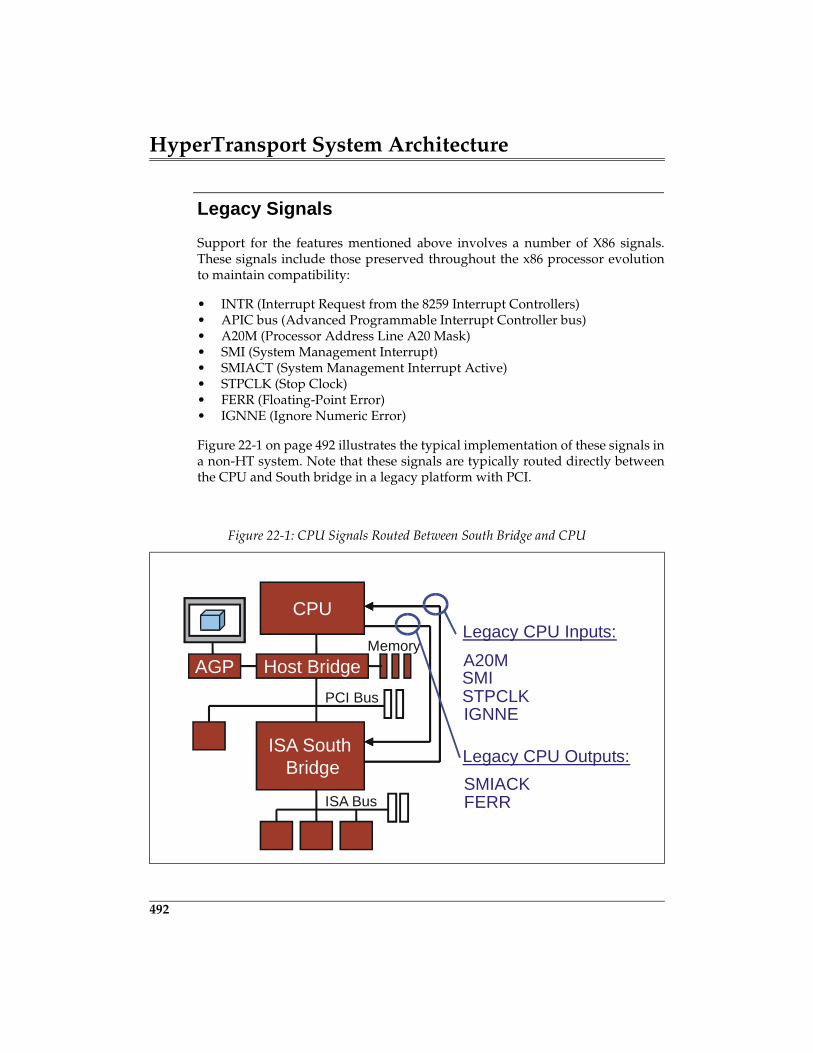
HyperTransport System Architecture
492
Legacy Signals
Support for the features mentioned above involves a number of X86 signals.These signals include those preserved throughout the x86 processor evolutionto maintain compatibility:
• INTR (Interrupt Request from the 8259 Interrupt Controllers)• APIC bus (Advanced Programmable Interrupt Controller bus)• A20M (Processor Address Line A20 Mask)• SMI (System Management Interrupt)• SMIACT (System Management Interrupt Active)• STPCLK (Stop Clock)• FERR (Floating-Point Error)• IGNNE (Ignore Numeric Error)
Figure 22-1 on page 492 illustrates the typical implementation of these signals ina non-HT system. Note that these signals are typically routed directly betweenthe CPU and South bridge in a legacy platform with PCI.
Figure 22-1: CPU Signals Routed Between South Bridge and CPU
Legacy CPU Inputs:
IGNNE
A20M
Legacy CPU Outputs:SMIACK
CPU
MemoryHost Bridge
ISA SouthBridge
ISA Bus
PCI Bus
AGPSTPCLK
FERR
SMI
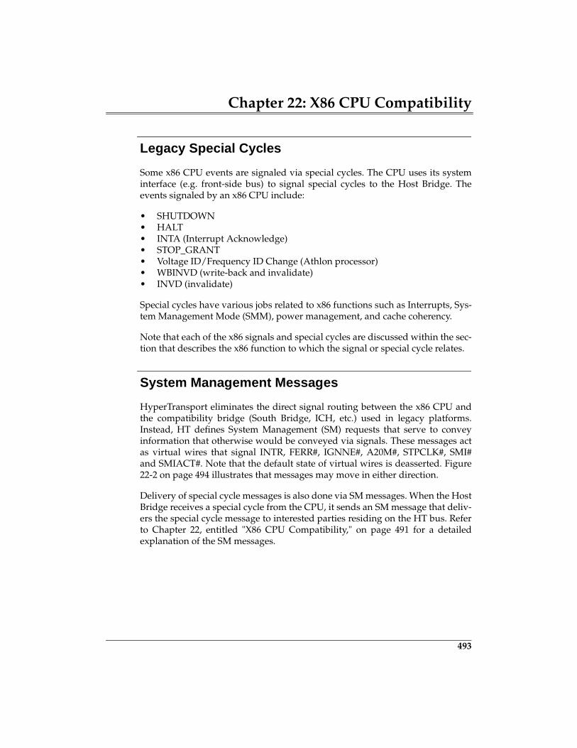
Chapter 22: X86 CPU Compatibility
493
Legacy Special Cycles
Some x86 CPU events are signaled via special cycles. The CPU uses its systeminterface (e.g. front-side bus) to signal special cycles to the Host Bridge. Theevents signaled by an x86 CPU include:
• SHUTDOWN • HALT • INTA (Interrupt Acknowledge)• STOP_GRANT• Voltage ID/Frequency ID Change (Athlon processor)• WBINVD (write-back and invalidate)• INVD (invalidate)
Special cycles have various jobs related to x86 functions such as Interrupts, Sys-tem Management Mode (SMM), power management, and cache coherency.
Note that each of the x86 signals and special cycles are discussed within the sec-tion that describes the x86 function to which the signal or special cycle relates.
System Management Messages
HyperTransport eliminates the direct signal routing between the x86 CPU andthe compatibility bridge (South Bridge, ICH, etc.) used in legacy platforms.Instead, HT defines System Management (SM) requests that serve to conveyinformation that otherwise would be conveyed via signals. These messages actas virtual wires that signal INTR, FERR#, IGNNE#, A20M#, STPCLK#, SMI#and SMIACT#. Note that the default state of virtual wires is deasserted. Figure22-2 on page 494 illustrates that messages may move in either direction.
Delivery of special cycle messages is also done via SM messages. When the HostBridge receives a special cycle from the CPU, it sends an SM message that deliv-ers the special cycle message to interested parties residing on the HT bus. Referto Chapter 22, entitled "X86 CPU Compatibility," on page 491 for a detailedexplanation of the SM messages.
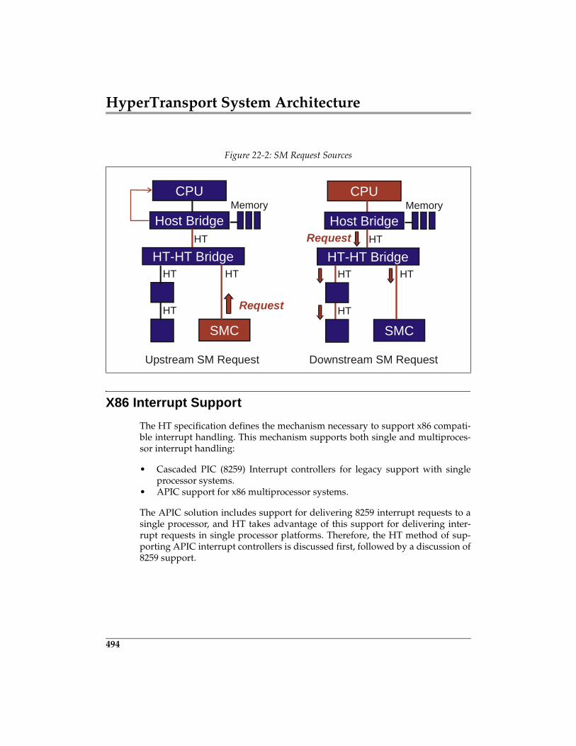
HyperTransport System Architecture
494
X86 Interrupt Support
The HT specification defines the mechanism necessary to support x86 compati-ble interrupt handling. This mechanism supports both single and multiproces-sor interrupt handling:
• Cascaded PIC (8259) Interrupt controllers for legacy support with singleprocessor systems.
• APIC support for x86 multiprocessor systems.
The APIC solution includes support for delivering 8259 interrupt requests to asingle processor, and HT takes advantage of this support for delivering inter-rupt requests in single processor platforms. Therefore, the HT method of sup-porting APIC interrupt controllers is discussed first, followed by a discussion of8259 support.
Figure 22-2: SM Request Sources
CPUMemory
Host Bridge
SMC
HT
HT-HT BridgeHTHT
HT Request
CPUMemory
Host Bridge
SMC
HT
HT-HT BridgeHTHT
HT
Request
Upstream SM Request Downstream SM Request
Chapter 22: X86 CPU Compatibility
495
APIC Interrupt Support
The APIC subsystem was designed to support multi-processing implementa-tions. The subsystem permits an interrupt to be directed to a particular proces-sor for handling or may deliver an interrupt to a group of processors and allowthem to arbitrate to determine which one will accept and service the interrupt.In addition to standard interrupt delivery, the APIC bus supports delivery ofother interrupts including 8259 interrupts, NMI (Non Maskable Interrupts), andSMI# (x86 System Management Interrupts).
Legacy Method of Handling APIC Interrupts
Figure 22-3 on page 495 illustrates a standard APIC subsystem implemented ina legacy-based system with a PCI-X expansion bus. The APIC subsystem is splitbetween the IO APIC located in the ICH and local APIC modules associatedwith each CPU. A synchronous APIC bus connects the IO APIC with the localAPIC modules of all processors.
Figure 22-3: Legacy APIC Implementation
CPU
X86 Host Bridge DDR SDRAM
ICH
SuperI/O
LPC
CPU
IO APIC
GBEthernet
PCI-X
SCSIRAID
Disk ArrayUSB
APIC Bus
LocalAPIC
LocalAPIC

Appendix
Glossaryof
Terms
Glossary
525
Address Map. The 1.04 revision of the HT specification defines a 40-bit memorymap. All resources which can be targeted with directed packets are mapped intothis space. In addition, reserved portions of the memory map are used for spe-cial purposes, including IO accesses, broadcast messages, interrupts, configura-tion cycles, etc.
AGP (Accelerated Graphics Port). A high-performance, point-to-point inter-face which connects a graphics adapter to the main memory controller in theMemory Controller Hub (MCH) or North Bridge (Host/PCI Bridge).
Atomic Read-Modify-Write Transaction. A hybrid read and write operationissued from one source, targeting main memory. An Atomic RMW is guaran-teed to complete without intervening accesses of the same location by any otherdevice. This command is useful when a memory semaphore is being updatedby one of the devices sharing it. HT supports two Atomic RMW variants: Fetchand Add and Compare and Swap.
Base Address Registers (BARs). Device configuration registers that define thestart address, length, and type of address space required and owned by adevice. The type of space implemented will be either memory or I/O. The valuewritten to this register during device configuration will program its addressdecoders to detect and accept accesses within the indicated range. Because HTmemory maps IO accesses, an IO request in the Base Address Register willresult in the assignment of a starting address in the memory map rangereserved for IO.
Bit Time. One half of a link clock period. As a double data rate (DDR) interface,HT CAD and CTL information is sent during each bit time, resulting in two bitstransferred, per signal, per clock.
Bridge. A device that provides a logical and electrical interface between twoindependent buses. Examples would be the bridge between the host processorbus and HyperTransport, a bridge between PCI/PCI-X and HT, or a bridgebetween two HT buses. Each secondary interface hosts a new bus (chain).
Broadcast Message. A special case of a posted write request which is used todeliver a message to all devices that see it. There is no specific target; eachdevice accepts it (based on the command type) and forwards it downstream.The end-of-chain device accepts the message, and drops it.
Broadcast Request. See Broadcast Message.
HyperTransport System Architecture
526
Bus Concurrency. Separate transfers occurring simultaneously on two or morebuses. Because HT is implemented with independent point-to-point connec-tions instead of a shared bus, HT concurrency can occur within the same chain.
Byte. 8 bits of digital information.
Byte Mask. In HT, there are no separate byte enable signals; data bus usage isimplied in the command type and the mask/count field which accompaniesrequest and response packets. For WrSized (byte) requests, a 32 bit “byte mask”precedes the 1-16 dword data packet and indicates valid bytes being sent —much like byte enables in PCI.
Byte Read. Sized read requests (RdSized) in HT carry a bit indicating whetherthe data to be transferred is in bytes or dwords. For byte reads, the maximumtransfer size is one dword (four bytes); the mask field in the request indicatesthe valid bytes being transferred. Any byte combination is valid.
Byte Write. Sized write requests (WrSized) in HT also carry a bit indicatingwhether the data to be transferred is in bytes or dwords. For byte writes, anycombination of bytes within a 32-byte, address aligned group may be trans-ferred. The count field in the request indicates the total dwords sent; valid byteswithin those dwords are indicated in the 32-bit byte mask which precedes thedata.
Cache. A relatively small amount of high-speed Static RAM (SRAM) that isused by CPUs to keep copies of code/data information recently read from sys-tem DRAM memory. Data from internal CPU caches may be accessed at fullinternal clock speed, avoiding a bus cycle to main memory.
Cache Line. When data is moved into or out of a cache, the transfer occurs infixed amounts called cache lines. The size of a cache line is cache design depen-dent, but typically is 32, 64, or 128 bytes.
CAD Bus. The CAD (Command, Address and Data) bus carries all information,control, and data packets between two devices on a link. There is one CAD busin each link direction, and bus width ranges from 2 bits to 32 bits wide.
Capability Registers. HT devices implement one or more sets of advancedcapability registers to support features beyond basic PCI compliance. Capabilityregister defined include: Host/Secondary interfaces, Slave/Primary interfaces,Interrupt Discovery and Configuration, Address Remapping, Revision ID, etc.
Cave Device. A single-link HT device. These always reside at the end of a chainand are also referred to as end devices.
Glossary
527
Chain. In HT, a logical bus may be comprised of multiple devices daisy-chainedtogether. At the top of the chain is a host bridge, in the middle there may bedual-link tunnel devices. At the end of a chain is a device with a single link con-nection to the chain. This may be a cave device, a tunnel device using only oneinterface, or the primary interface of a bridge to a new chain (bus).
Chain Down Error. In HT, each device is required to track outstanding requestsuntil a response is returned. A chain down error is said to have occurred if a linkgoes down between the time a non-posted request is issued and its responsereturns. A reset will flush any pending requests after a chain down error.
Chain Fail. A chain fail occurs when a Sync flood or an event that can cause oneis detected. Each device which detects the event sets the chain fail bit in its ErrorHandling register. The bit is cleared on reset.
Clocking Modes. HT supports three clocking modes of a link receiver interfacewith respect to the corresponding transmitter: synchronous clocking, pseudo-synchronous clocking, and asynchronous clocking.
Coherency. If the information resident in a cache accurately reflects the originalinformation in DRAM memory, the cache is said to be coherent or consistent. InHyperTransport, transactions targeting DRAM main memory may eitherrequire action to guarantee coherency, or not. The coherent bit in WrSized andRdSized request packets indicates whether or not the host bridge must takecoherency actions (cause a snoop of the CPU caches, etc.).
Coherent Bit. See Coherency.
Command Code. Each HyperTransport control packet contains a 6-bit com-mand code in the first byte. This information informs other devices of theintended operation and the format of the remainder of the packet. Some of the6-bit command codes include options bits which may be used to indicatewhether the packet is to travel in the isochronous channel, is posted or not, etc.
Compatibility Bit. The compatibility bit (Compat) in an HT request is set by thehost bridge to indicate the packet must be forwarded down the compatibilitychain in the direction of the compatibility bridge where it will be accepted,regardless of the address it carries. The use of this bit provides compatibilitywith the South Bridge subtractive decoder in PCI systems where transactionswhich are otherwise unmapped in the system may be claimed by the subtrac-tive decoder and forwarded to the compatibility bus (e.g. ISA).
HyperTransport System Architecture
528
Configuration Cycle. A link transaction to read or write the contents of adevice's configuration registers is called a configuration cycle. In HT, configura-tion accesses are performed using RdSized and WrSized requests targetingaddresses reserved for configuration type 0 and type 1 cycles.
Configuration Space. Each HT device is required to implement the 256 byteconfiguration space required of all PCI-compliant devices. Because PCI permits256 busses in a system, 32 logical devices per bus, and 8 functions per device,the total configuration address space to reach all possible devices and functionsis 16MB (256 busses x 32 devices x 8 functions x 256 bytes = 16MB). HT memorymaps the entire configuration address space in a 32 MB reserved address range;the lower 16MB of the reserved range is for type 0 configuration cycles and theupper 16MB of the reserved range indicates type 1 configuration cycles.
Configuration Header Region. The first one-fourth of the configuration space(64 bytes) has a well-defined format and is referred to as the configurationheader region. The two key header formats are type 0 (non-bridge) and type 1(HT bridges or bridges between HT and other compatible protocols (PCI, PCI-X, or AGP).
Consistency. See Coherency.
Control Packet. Control packets include information, request, and responsetypes. Information packets are used for local communication between the trans-mitter-receiver pairs on each link. Request packets may be 4 or 8 bytes, and areused to initiate transactions. Response packets are 4 bytes and are returned bythe target of each non-posted request.
CRC. In HT, a Cycle Redundancy Code (CRC) is used to assure the integrity oftransmitted data. Starting after reset, each transmitter on each link interface cal-culates a 32-bit CRC value and periodically sends it to the correspondingreceiver where it is checked against the value calculated as CAD packets arrive.CRC is calculated independently for each 8 bits of CAD width. The error han-dling strategy for handling CRC errors is programmable.
CRC Testing Mode. HT provides a method for stress-testing CRC checking atthe receiver. If both devices on a link support the CRC test mode, a transmittercan enter the CRC test mode under software control and generate dummy pack-ets which are checked for CRC validity by the receiver, then dropped.
CTL Signal. The link control (CTL) signal is driven by each transmitter to indi-cate to the receiver that control packet information is in transit over the CADbus; when CTL is deasserted by the transmitter, a data packet is in transit. Thereceiver uses the CTL signal to demultiplex control and data packets.
Index
541
NumericsCount[3:0] 76, 91Mask[3:0] 76, 78Addr[39:2] 22Command 69, 74, 146, 151, 154, 156, 162, 164, 168, 170, 175, 176, 180, 183, 185, 190, 192, 194, 1958259 EOI Command 5078259 Interrupt Compatibility 505
AA20 Mask Support 508Accepting Packets 264Address Map 23, 202, 312, 446Address Remapping 477Address Remapping Capability Block 419, 478, 479Address Remapping Capability Block Format 479Address-Based Semantics 21, 22Advanced Capability Registers 323AGP Compatibility 470AGP Ordering 471APIC Interrupt Support 495Asynchronous Clock Mode 402Atomic Operations 46Atomic Read-Modify-Write 46, 66, 75, 89, 91, 182, 250, 261
BBandwidth per Pin 17Base Address Register 329, 424Bit-Time 294, 381Broadcast 263Broadcast Message 46, 70, 75, 82, 83, 207, 261, 266, 521Broadcast Request 220, 263, 268Bus Numbering 318
Byte Mask 141, 159, 160, 252, 466Byte Read 37, 78, 79, 96, 167Byte Write 42, 78, 79, 156
CCache Line Size Register 329, 425CAD Signal Group 55CAD Signals 28, 30, 35, 55, 291, 292, 294, 365, 388Capabilities Pointer 209, 328, 330, 334, 355, 414, 425Capability Command Register. 266Capability ID 209, 324, 331, 334, 355Capability Registers 50, 225, 245, 276, 299, 300, 308, 323, 470Capability Type 209, 332, 336Cave 20, 33Cave Device 243, 245, 259, 321, 333Chain 20, 33, 82Chain Down Error 230, 247Chain Fail 247, 350, 351Chain Initialization 316, 318CLK Signal 28, 35, 55, 383Clock Distribution Skew 392Clock Frequency Tuning 299Clock Initialization 388Clock Signals 55Clock Variance Timing Budget 393Clocking Mode 388, 394, 401Coherent Bit 488Cold Reset 276Command Register 325, 410Compare and Swap 70, 90, 184, 188Compatibility Bit 82, 152, 260, 264, 269, 326, 463, 488Configuration 434Configuration Cycle Types 309
Index
542
Configuration Cycles 75, 82, 267, 306, 308, 309, 310, 311, 313, 315, 316, 408, 429, 434, 444Configuration Space 117, 200, 230, 306, 308, 310, 311, 408, 434, 470Configuration Space Mapping 312Consortium URL 16, 17Control Packet 28, 35, 55, 65, 140, 238Control Packet Format 69Control Packet Types 36CRC 50, 58, 231, 232, 234, 235, 242, 254, 282CRC Test Mode 237, 337CRC Window 223, 282, 294Cross-Byte Skew 391CTL Signal 35, 55, 67, 68, 104, 231, 237, 294, 349, 365
DData Coherency 120Data Packet 28, 35, 66, 67, 140, 263, 506Data Packet Types 37Direct Memory Access 25, 121Directed Requests 263, 266, 267, 268DMA Primary Base Register 480DMA Remapping 480DMA Secondary Base and Limit Registers 481DMA Transactions 121DMA Transfers 25DMA Window Control Register 480Double-Host Chain Initialization 320
Double-Hosted Chain 137, 320, 428, 431, 432, 433, 434Double-Hosted Chain Ordering 137Downstream Ordering Rules 123, 136Dword Read 37, 79, 161, 164Dword Write 67
EEnd of Chain 230, 243, 265, 432End of Interrupt 200, 207, 502, 507Enumeration Scratchpad Register 360EOI Packet Format 208, 209EOI Request Message Format 503Error Bit 42, 49, 241, 243, 250, 251Error Conditions 230Error Handling Register 230, 234, 247, 350, 360Error Interrupts 230Error Logging 234, 239, 241, 243, 245, 249, 307Error Reporting 60, 234, 239, 242, 246, 250, 259, 517Error Response 230, 250, 251Error Signaling 58
FFairness Algorithm 48, 258, 272Fairness and Forward Progress 271, 272Fatal Interrupt 231, 234, 252Feature Capability Register 347, 348, 359Fence Request 45, 87, 88, 179, 180Fence Transactions 45Fetch and Add 90, 184
Index
543
FIFO Size Calculation 394flow 101Flow Control 36, 42, 47, 58, 65, 68, 71, 99, 101, 103Flow Control Buffers 71, 75, 104, 105, 106, 107, 145, 241, 452Flow Control Counters 107Flush Request 39, 44, 66, 84, 86, 97, 173, 175, 176Flush Transactions 44Forwarding Packets 259, 265, 271Frequency Capability Register 299
GGlobally Ordered 134, 136Globally Visible 84, 124, 134, 135
HHigh-Speed Signals 28, 55Host Bridge 24, 34, 39, 82, 121, 132, 137, 200, 216, 220, 226, 258, 267, 270, 307, 316, 320, 428, 432, 436, 446, 493Host Ordering 132Host/Secondary Interface 354, 355, 409HyperTransport Consortium 16HyperTransport Protocol Charac-teristics 16HyperTransport-to-HyperTrans-port Bridge 318, 408, 409
II/O Address ReMapping 481I/O Base and Limit Registers 420, 482I/O Stream 37, 39, 137Information Packet 36, 65, 71, 115, 145, 259
Initialization Complete 266, 295, 317Interleaving Control and Data Packets 67Interrupt Capability Block Format 209Interrupt Definition Register 209, 210, 211, 500Interrupt Discovery and Configu-ration Capability Block 200, 209, 210Interrupt Information Fields 205Interrupt Line Register 330, 425Interrupt Pin Register 330, 425Interrupt Request Data Packet 206Interrupt Request Packet 204Interrupt Request Packet Format 205Interrupt Requests 204Interrupt Signaling 58Interrupt Type Field 205Isoc Bit 116, 360Isochronous Channel 37, 48, 73Isochronous Flow Control 75, 116, 348Isochronous Transactions 48
LLatency Timer Register 329, 424LDTREQ# 29, 30, 57, 366, 436, 439, 440, 441LDTSTOP# 29, 30, 57, 72, 216, 223, 225, 226, 282, 300, 304, 365, 436, 437LDTSTOP# Signaling 438Legacy Numeric Error Handling 516Legacy Signal Support 492
Index
544
Link Configuration Register 282, 288, 295, 337, 339, 358Link Control Register 73, 225, 227, 234, 244, 295, 317, 336, 358, 432Link Error Register 238, 239, 241, 245, 345, 359Link Frequency Capability Regis-ter 282, 299, 346Link Frequency Register 300, 301, 344, 399Link Initialization 282, 288Link Initialization Disconnect 225Link Management Overview 47Link Support Signals 29Link Width Initialization 282, 283Link Width Tuning 295Low-Level Link Initialization 282, 291, 433Low-Speed Signals 56
MMaster Host Bridge 320, 431, 432Max_Latency Register 330Memory Base and Limit Register 419, 485Memory Base Upper Register 352Memory Map 23, 312, 446Message Semantics 21, 450Min_Grant Register 330Minimum FIFO Size 395
NNetworking Support 17Non-Fatal Interrupt 234, 249Non-NXA Error 247Non-Posted Request 66, 94, 105, 108, 125, 132, 135, 250Non-Posted Sized Writes 42
Non-Sharing Double-Hosted Chain 432NOP Packet 67, 71, 104, 109, 116, 145, 146, 148, 223, 259NXA Error 251
OOrdering Rules, HT 122
PPacket Framing 294Packet Rejection 265, 266Packetized Transfers 35PassPW Bit 45, 124, 126, 127, 128PCI Ordering 458, 459, 460PCI-X Ordering 467Pin Count 31Point-to-Point Interconnect 14Posted Request 37, 44, 45, 58, 70, 77, 80, 81, 105, 108, 111, 125, 127, 130, 131, 136, 241Posted Sized Writes 43Posted Write 37, 43, 44, 45, 70, 84, 125Prefetchable Memory Base and Limit Registers 419, 486, 487Primary Latency Timer Register 424Processor VID/FID 437Producer/Consumer Model 458, 459, 472Programmed I/O 24, 41Programmed I/O Transactions 121Protocol Errors 230, 237, 238, 239, 345, 350Pseudo-Synchronous Clock Mode 399
Index
545
Pseudo-Synchronous Clocking Mode 401PWROK 29, 49, 56, 223, 280, 281, 302, 356, 365, 378
RRead Request 66Read Response 36, 37, 66, 70, 94, 262Receive Buffer Overflow 50, 230, 241Receive FIFO 110, 282, 290, 388, 401Receiver Flow Control Counters 108Request EOI Field 206Request packet 65Request Packet Types 36Reset 27, 29, 49, 56, 74, 110, 223, 276, 278RESET# 29, 49, 56, 223, 247, 277, 278, 302, 304, 365, 378Response Errors 50, 230Response packet 66Response Packet Types 36Revision ID Capability Block 361Revision ID Register 343Routing Packets 258
SScalability 15, 20, 30Scalable Bandwidth 20Scalable Clock Speed 32Scalable Data Width 31Secondary Bus Non-Prefetchable Window Base 480Secondary Bus Non-Prefetchable Window Control Register 480
Secondary Bus Prefetchable Win-dow Control Register 480Secondary Bus Window Base regis-ter 488Secondary Status Register 254, 415Sequence ID 39, 75, 124, 125Signal Groups 54Signaling Interrupt Acknowledge 507Signaling INTR 506Sized Byte Read 37, 79, 507Sized Byte Write 37, 79Sized Dword Read 37, 79Sized Read 70, 75Sized Read Transactions 41Sized Write 75Sized Write Transactions 42Slave Host Bridge 320, 431Slave/Primary Interface 332, 333SM Request Packet Format, Down-stream 220SM Request Packet Format, Up-stream 218SM Request, Sources of 216Source Tag 39, 94Special Cycles 493, 521Specification 1.04 20Status Register 230, 307, 326, 413, 415Stop Clock Signal 441STOP_GRANT Cycles 438Storage Semantics 446, 447STPCLK# 441STPCLK# Signaling 442Strongly Ordered Sequence 126
Index
546
Subtractive Decode 77, 82, 264, 412, 461Sync Flood 230, 235, 253Sync Pattern 74Sync/Error Packet 74Synchronous Clock Mode 389Synchronous Clocking Interface 390System Block Diagram 21System Management 216, 436, 493System Management Address Range 217System Management Commands, Upstream 221System Management Mode 493, 511
TTarget Done 36, 37, 39, 66, 94, 97Transaction Requests 40Transaction Responses 40Transaction Stream 39, 125, 137Transaction Types 41Transmit and Receive FIFOs 110Transmitter Flow Control Counters 109Tunnel 20, 33, 105, 125, 244, 271, 300, 321, 333Type 0 Configuration Cycle 267, 310, 314, 315, 434Type 1 Configuration Cycle 309, 314, 432
UUnit ID 77, 94, 125, 154, 179, 243, 268, 316Upstream Ordering Rules 122, 123, 125
VVirtual Channel 37, 38, 69, 105, 125, 447, 451Virtual Channel Buffers 38
WWakeup Signaling 439, 440Warm Reset 302Write Request 42, 43, 66, 75
XX86 Power Management Support 441X86-Based Interrupt Request Mes-sage Format 502