HYLAS 1 INSTALLATION MANUAL -...
79
HYLAS 1 INSTALLATION MANUAL YOUR GUIDE TO INSTALLING SATELLITES FOR CONNECTION TO HYLAS 1
Transcript of HYLAS 1 INSTALLATION MANUAL -...

HYLAS 1 INSTALLATION MANUAL
YOUR GUIDE TO INSTALLING SATELLITES FOR CONNECTION TO HYLAS 1
.2 Avanti Installation Manual 1.1
GENERAL
1. Overview ....................................................................................................... 03
2. Purpose ........................................................................................................03
3. Objective ......................................................................................................03
4. Install Summary ...............................................................................................04
5. Tooling requirements ........................................................................................06
6. Consumable requirements ..................................................................................08
7. Health and Safety ............................................................................................09
8. Quality Assurance ........................................................................................... 15
SITE HARDWARE PREPARATION
9. Site Assessment And Survey ................................................................................16
10. Bracket selection and installation .........................................................................24
11. Prodelin model AN8-074P .74m Antenna Assembly ....................................................33
12. Cabling .........................................................................................................46
TERMINAL COMMISSIONING AND ANTENNA ALIGNMENT
13. Terminal connection .........................................................................................57
14. Antenna Alignment Methods ...............................................................................59
15. Commissioning the 9200 terminal using AFA software ............................................70
CONNECTION TESTING AND CUSTOMER REPORTING
16. Terminal testing and demonstration.......................................................................76
17. Useful Tools....................................................................................................78
18. Reporting and sign acceptance certificate ...............................................................79
19. Completing the report with AFA ............................................................................81
20. Clearing site .................................................................................................. 85
21. Return Material Request (RMA) Process ................................................................. 86
.3 Avanti Installation Manual 1.1
General
1. OVERVIEW
This document is a guide to installation techniques, standards and best practice for use when installing Avanti
Broadband satellite systems. Covered in this manual are all aspects of an installation using the Hughes 9200
terminal modem and the Hughes/Raven AN8-074R 0.74cm satellite antenna / transceiver unit. It is written for
Avanti accredited installers who are familiar with satellite installation practices and are capable of properly
applying the information contained herein.
2. PURPOSE
Using this manual will enable a installation engineer to install and commission Avanti Broadband systems
correctly and to the highest standards ensuring that the highest standard of health and safety are maintained
during the installation and installed equipment is fitted to a safe, high standard. Covered in this manual are
all standard installation methods, specifications, and tooling requirements.
3. OBJECTIVE
After thorough reading of this manual all engineers will be able to complete the highest quality satellite
broadband installation, commission, test and demonstrate to a customer the working broadband system is to
the standard expected for this type of service.
This manual aims to provide Installers with a good scope of works and step by step methodology to achieve
a successful installation. The below steps are covered in depth within this manual and ensure you are fully
conversant with all requirements before attempting to complete a system installation.

.4 Avanti Installation Manual 1.1
General
4. INSTALLATION SUMMARY
Line of site check and survey assessment
Risk assessment and method statements Selecting and Mounting antenna bracket
Cabling standard
Correct termination using compression connectors
Assembly of Prodelin AN8-074PO antenna
Connection of Avanti/Hughes 9200 terminal
Pre-antenna alignment terminal commissioning
Antenna alignment
Auto commission of Avanti/Hughes 9200 terminal
Terminal testing and customer demonstration
Signoff and reporting

.5 Avanti Installation Manual 1.1
General
9. Antenna Alignment
Complete AFA reporting
INSTALLATION OVERVIEW
1. Line of Sight and Survey Assess Line of Sight Verify Line of Sight using inclinometer and compass
Assess Bracket position and cable entry point
Assess customer terminal installation point
2. Risk Assessment and Method Statement
Complete Online Risk assessment in AFA or
manual form
Complete Method Statement
in AFA or manual form
3. Selecting and Mounting Antenna Bracket Select suitable bracket type Locate and mount bracket
Check level for trueness/ plumb
4. Cabling Standard Select cable type Secure cable Cable entry point/
waterprrofing
5. Correct Termination using compression connectors
Select correct connectors for cable type
Terminate cable using selected connectors
6. Assembly of Prodelin AN8- 074PO Antenna Assemble antenna Assemble transceiver Check waveguide alignment
Mount transceiver to dish structure
7. Connection of Avanti/Hughes 9200 Terminal
Connect Rx Tx Cables at terminal
Connect commissioning laptop via Ethernet
8. Pre Antenna alignment terminal commissioning
Set pre-configuration data, using AFA Input GPS
Select Satellite and beam criteria
Set terminal to Antenna Alignment mode
Horizon HD-S2 connection using DC bypass splitter Coarse pointing mode Fine pointing mode
Antenna lock down and verification
10. Auto Commission of Avanti/ Hughes 9200 Terminal
Run Avanti Field Assist – (AFA)
11. Terminal Testing and Customer Demonstration Ping Test Browsing Test Speed Test Customer Demonstraton
12. Signoff and Reporting Complete Customer Sign off
Sheet Add required photos to AFA Complete
report

.6 Avanti Installation Manual 1.1
General
5. TOOLING REQUIREMENTS
The following are tools which Avanti recommends are used for a successful installation
5.1 HAND TOOLS
5.1.1 Sockets & Spanners • 3/8 Torque Ratchet, Torque Requirement 5 ft/lb (Norbar part number NORSL0PK) model
NORSL0PK • 1/2 Standard Ratchet • 1/2 Deep Socket 1/2 drive • 1/2 Deep Socket 3/8 drive
• 7/16 deep socket 3/8 drive
• 17mm deep socket ½ drive
• 16mm Deep Socket 1/2 drive
• 13mm Deep Socket 3/8 drive
• 10mm Deep Socket 3/8 drive
• 8mm Shallow Socket 3/8 drive • 1/2 Combination Spanner • 10mm Combination Spanner
• 11mm Combination Spanner
• 13mm Combination Spanner
• 16mm Combination Spanner
• 17mm Combination Spanner
• 7/64 Torque Allen driver / key
5.1.2 Cutting Tools • Stanley Knife • Side Cutters • Engineers Hacksaw
5.1.3 Screwdrivers • Flat Blade – Selection • Posi-drive – Selection
5.1.4 Cable Tools • Cable Stripping Tool • Cable Insertion Tool • ‗F‘ Connector Compression Tool • Rubber Cable Grip • CAT5e Cable Stripper • CAT5e Crimp Tool • 11mm ‗F‘ Connector Torque Tool, Torque Requirement 30 in/lb • 14mm ‗F‘ Connector Torque Tool , Torque Requirement 30 in/lb

.7 Avanti Installation Manual 1.1
General
5. TOOLING REQUIREMENTS
5.1.5 Other Tools • Pliers Standard • 22oz Claw Hammer • Magnetic Bullet Spirit Level • Mastic Gun • Mole/Vice Grips • Spade • Trench Spade • Ground Auger • Electricians Fish Wire • Post Spirit Level
5.1.6 Survey & Reporting Tools • Camera, capable of image transfer to laptop 2Meg minimum picture quality. • GPS Device, i.e. Garmin E-Trex
• Tandem Inclinometer/compass
• Laptop
• Horizon meter HD-S2 with ACM software.
5.1.7 Power Tools Drill • 5mmx100mm Masonry • 16mmx200mm Masonry • 16mmx600mm Masonry • 16mmx1000mm Masonry • 16mm Wood Auger • Set of steel bits • Angle Grinder – Cordless • Mains Tester
5.1.8 Height Tools • Ladders • Roof (cat) Ladders • Height Safety Equipment • Ladder Safety Equipment

.8 Avanti Installation Manual 1.1
General
6. CONSUMABLE REQUIREMENTS
Standard Installation Consumables
Mount converter 76mm to 60mm. NOTE:
Cable ties 300mm black / white /clear. ALL INSTALLATION ENGINEERS SHOULD HAVE
WF100 Cablecon 5.1 compression connector. ACCESS TO THE COMPLETE INSTALLATION
WF125 Cablecon 6.0 compression connector. CONSUMABLES LIST OPPOSITE TO ENSURE
Hi-grade multi use barrel F-F connector. ALL INSTALLATIONS CAN BE COMPLETED ON
Silicon Dielectric grease. THEIR SCHEDULED DATE.
Silicon based self – amalgamating tape. RX and TX labels. M8-M10 Rawl-bolts. WD 40 or equivalent. WF100 Twin-sat CAI approved foam dielectric.
Installation Consumables.
BRACKETS and FIXINGS. CABLE.
Standard 60mm „L‟ bracket short. 35cm WF100 Twin-sat CAI approved foam dielectric.
Standard 60mm „L‟ bracket long. 55cm WF125 green direct burial CAI approved.
K+K or „A„ frame (Both to have support leg) Cat5e external grade 100 meter.
20cm / 8in. Cat5e 2 meter straight patch lead.
46cm / 18in. 4 gang surge protected mains extension.
55cm / 24in. Twin-sat 7 mm Grommet black / white.
60mm / 2meter or 3meter pole. 7 mm grommet black / white.
‗V‘ bolts for 60mm pole including washers. 10 mm grommet black / white. (WF125)
Universal Clamp. Cable clips 2 x 7mm masonry grade.
Non penetrating roof mount 60mm. Cable clips 9mm round masonry grade.
4 x 600mm x 600mm x 50mm flags. Cable clips 6-7mm round masonry grade.
M10 / 16mm Rawl-bolts. Pin plugs.
Rapid set postcrete. Brick plate terracotta.
DRILL BITS. Brick plate white.
16mm 200mm masonry External grade clear silicon.
16mm 600mm masonry Cable ties 300mm black / white /clear.
16mm 1000mm masonry CONNECTORS.
5.5mm 100mm masonry WF100 Cablecon 5.1 compression connector.
Grinder cutting disks. WF125 Cablecon 6.0 compression connector.
Hi-grade multi use barrel F-F connector.
Silicon Dielectric grease.
RJ 45 connectors.
Silicon based self – amalgamating tape.
Replacement Cable stripper blades.
RX and TX labels.

.9 Avanti Installation Manual 1.1
General
7. HEALTH AND SAFETY
General health and safety for installing vsat systems. For your safety and protection, read this entire installation guide before attempting to install any
Avanti Broadband system. In particular, read this safety section carefully. Keep this safety information
where you can refer to it if necessary.
7.1 PRODUCT WARNING LABELS
The following safety alert labels are affixed to the antenna feed support arms, radio transmitter, and antenna
reflector, respectively.
POWER
FEED SUPPORT ARMS
RADIO TRANSMITTER
These labels advise that the antenna emits radio frequency (RF) energy. Because of this potential safety hazard,
observe all cautions on these labels and in the next section, Antenna installation safety.
.10 Avanti Installation Manual 1.1
General
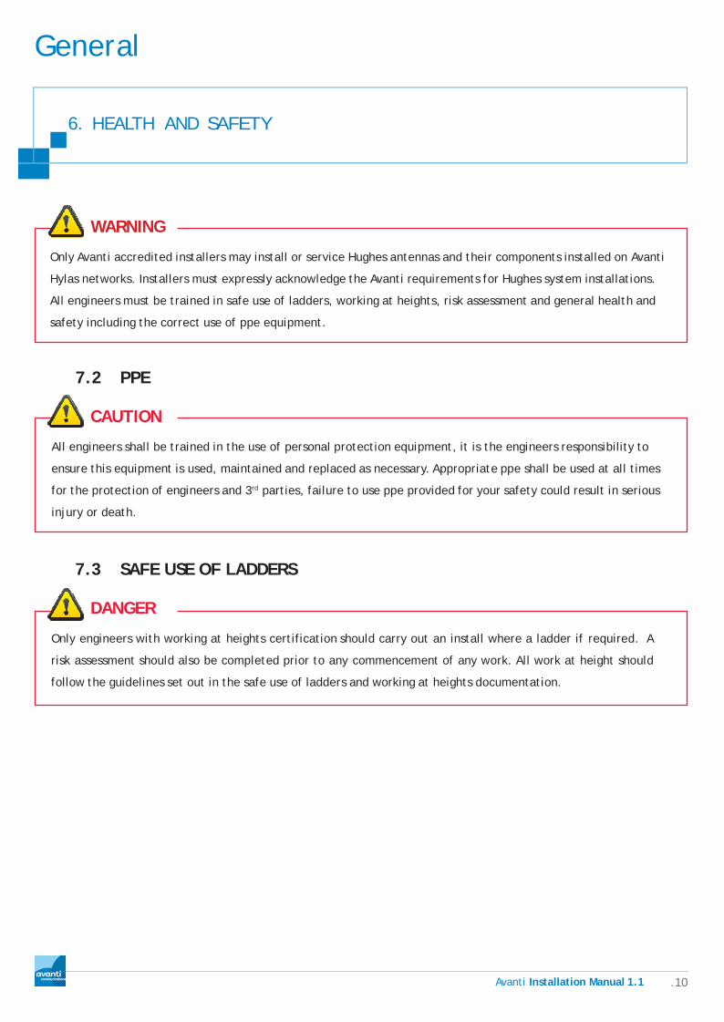
6. HEALTH AND SAFETY
WARNING
Only Avanti accredited installers may install or service Hughes antennas and their components installed on Avanti
Hylas networks. Installers must expressly acknowledge the Avanti requirements for Hughes system installations.
All engineers must be trained in safe use of ladders, working at heights, risk assessment and general health and
safety including the correct use of ppe equipment.
7.2 PPE
CAUTION
All engineers shall be trained in the use of personal protection equipment, it is the engineers responsibility to
ensure this equipment is used, maintained and replaced as necessary. Appropriate ppe shall be used at all times
for the protection of engineers and 3rd parties, failure to use ppe provided for your safety could result in serious
injury or death.
7.3 SAFE USE OF LADDERS
DANGER
Only engineers with working at heights certification should carry out an install where a ladder if required. A
risk assessment should also be completed prior to any commencement of any work. All work at height should
follow the guidelines set out in the safe use of ladders and working at heights documentation.
.11 Avanti Installation Manual 1.1
General
7. HEALTH AND SAFETY
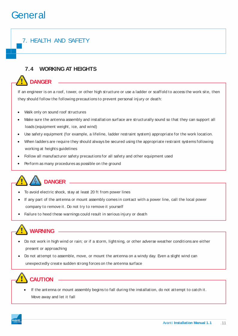
7.4 WORKING AT HEIGHTS
DANGER
If an engineer is on a roof, tower, or other high structure or use a ladder or scaffold to access the work site, then
they should follow the following precautions to prevent personal injury or death:
• Walk only on sound roof structures
• Make sure the antenna assembly and installation surface are structurally sound so that they can support all
loads (equipment weight, ice, and wind)
• Use safety equipment (for example, a lifeline, ladder restraint system) appropriate for the work location.
• When ladders are require they should always be secured using the appropriate restraint systems following
working at heights guidelines
• Follow all manufacturer safety precautions for all safety and other equipment used
• Perform as many procedures as possible on the ground
DANGER
• To avoid electric shock, stay at least 20 ft from power lines
• If any part of the antenna or mount assembly comes in contact with a power line, call the local power
company to remove it. Do not try to remove it yourself
• Failure to heed these warnings could result in serious injury or death
WARNING
• Do not work in high wind or rain; or if a storm, lightning, or other adverse weather conditions are either
present or approaching
• Do not attempt to assemble, move, or mount the antenna on a windy day. Even a slight wind can
unexpectedly create sudden strong forces on the antenna surface
CAUTION
• If the antenna or mount assembly begins to fall during the installation, do not attempt to catch it.
Move away and let it fall
.12 Avanti Installation Manual 1.1
General
7. HEALTH AND SAFETY
WARNING
• Antennas that have been improperly installed or attached to an unstable structure are susceptible to
wind damage, which can be very serious or even life threatening. The product owner and installer
assume full responsibility that the installation is structurally sound to support all loads (weight, wind,
and ice) and is properly sealed against leaks
7.5 RADIATION HAZARDS
CAUTION
Observe these precautions to avoid exposure to RF radiation, a potential safety hazard:
• The antenna must be installed in a location not readily accessible to children and in a manner that prevents
human exposure to potentially harmful levels of radiation
• Antennas mounted at any site with a greater than 30° elevation angle must be installed such that the lower
lip of the antenna reflector is at least 5 ft above any surface upon which a person might be expected to
stand, and 3 ft 3 inches from any opening (such as a door or window) in a building or adjacent structure
• Antennas mounted at any site with a less than 30° elevation must be installed such that the lower lip of
the antenna reflector is at least 5 ft 9 inches above any surface upon which a person might be expected to
stand, and 3 ft 3 inches from any opening (such as a door or window) in a building or adjacent structure
• The antenna must be mounted such that no object that could reasonably be expected to support a person is
within 6 ft 7 inches of the edges of a cylindrical space projecting outward from the antenna reflector toward
the satellite
• If the above distance requirements cannot be met, the antenna must be mounted in a controlled area
inaccessible to the general public, such as a fenced enclosure or a roof
• A fenced installation must have a locked entry, and the fenced area must be large enough to protect the
general public from exposure to potentially harmful levels of radiation
• Access to a roof installation in a commercial, industrial, or institutional environment must be limited by a
door or a permanently fastened ladder that is locked to deny access to the general public.
• Once the transmitter becomes operational, maintain a safe distance; at least 3 feet
• Failure to observe these cautions could result in injury to eyes or other personal injury

.13 Avanti Installation Manual 1.1
General
7. HEALTH AND SAFETY
CAUTION
• All antennas of any type or size must carry an industry standard and government approved Radiation Hazard
Caution label on the feed support arm
• A fenced or roof installation in a commercial, industrial, or institutional environment must carry a Radiation
Hazard Caution sign on the access door, gate, or permanently mounted access ladder within plain sight of
anyone approaching the antenna from the front or sides of the reflector
• Failure to observe these cautions could result in injury to eyes or other personal injury
CAUTION
• No Satellite antenna over 60cm shall be mounted onto a chimney stack under any circumstance as
this contravenes planning and building regulations
7.6 COSHH
CAUTION
• All substances identified under ―control of substances hazardous to health‖ shall be recorded and
the relevant product data sheets will be issued to all engineers effected. These substances will be
namely:- silicon sealant, silicon grease, wd40 and postcrete
7.7 RISK ASSESSMENT
CAUTION
All engineers shall carry out a full risk assessment prior to commencement of any work; the details obtained
from this activity shall be recorded on a risk assessment form, or submitted electronically via AFA when
available. It is the responsibility of all engineers to ensure that a accurate risk assessment is completed,
submitted and acted on during any installation works. Any risks that are identified must be removed or
controlled where this is not possible, your line manager must be contacted immediately for further guidance,
no work must be carried out until the risk has been removed or sufficient control measures have been put in
place to reduce the identified risk to a satisfactory, controlled level.

.14 Avanti Installation Manual 1.1
General
7. HEALTH AND SAFETY
7.8 METHOD STATEMENTS
All engineers should complete a full method statement alongside the risk assessment detailed above. This
method statement should detail the installation requirements and the methods that will be used to complete
the installation using the control measures identified during the risk assessment.

Ava n ti Installation Manual1.0 .15
General
8. QUALITY ASSURANCE
All installations automatically go through a period of quality monitoring, as well as this customer site are
visited and thoroughly inspected to ensure the guidelines in this document have been implemented
correctly. All installations will be analysed and reports generated to identify installation related issues.

Ava n ti Installation Manual1.0 .16
Site Hardware Preparation
9. SITE ASSESSMENT AND SURVEY
1. Explain the installation process to the customer.
2. Conduct a site survey of the purposed antenna location to confirm the location will have clear line of sight to
HYLAS 1 at 33.5° west.
9.1 ANTENNA LOCATION.
Care must be taken when choosing a location for the antenna, consideration should be given to the
building fabric and it‘s suitability for mounting a large antenna to.
o Suitable mounting locations should be of brick, block, stone or concrete construction.
o Antennas should be mounted well above head height where possible.
o Working at height guidelines should be observed, mounting the antenna at a safe height. No antenna
should be mounted at extreme heights purely for cosmetic reasons, this will be governed by line of sight.
o Be careful not to select a location that will obstruct windows, doorways, walkways or vehicle access routes.
o Line of sight should be checked from the proposed location using a inclinometer to ensure a clear view
of the satellite can be obtained.
o When choosing antenna location make sure it is safe to erect a ladder up to the antenna mounting
position, also consider any access required along any cable routes to the entry point.
o Try to minimise cable length, by mounting antenna as close as possible to entry point.
o If there is a choice of antenna location, choose the site that is most aesthetically pleasing, as long as it
does not affect safety during the installation, or Line of Sight.
CAUTION
o Do not mount bracketry on top few course of brick as this is a weak point in wall structure, all
brackets should be a minimum of 50cm from any wall edge.
o Antennas should not be mounted directly onto a timber structure.
o Antennas should not be mounted on any chimney.
o Try to avoid installing the antenna or bracketry below head height to remove risk of people injuring
themselves by walking in to it, and also remove any exposure risk from radiation emissions. If this is
essential make sure it is clearly marked and physically access is restricted by a fence and locked
gate.
o Consideration must be given when installing equipment in situations where it may be struck by
moving vehicles or machinery, especially on farms or industrial properties, check with the customer
as to the types and heights of vehicles that may operate in the area of the antenna.
Ava n ti Installation Manual1.0 .17
Site Hardware Preparation
9. SITE ASSESSMENT AND SURVEY
9.2 LINE OF SIGHT
Line of sight is probably the most important aspect of the satellite broadband installation, this will determine
how good a signal can be achieved and therefore the performance of the broadband connection.
CAUTION
Failure to obtain clear line of sight will result in a degraded signal and therefore a poor intermittent
broadband service or no connection and no service at all. It will also affect the commissioning of the terminal
which will ultimately fail.
To ascertain whether a good line of sight is possible the following process should be followed.
Use a net resource i.e. `antennapointer.com` to check pointing details for the postcode you are going to be
installing at, you will require the magnetic azimuth and the elevation for install location before arrival on
site. These details can also be obtained by inputting the Gps coordinates into the Hughes terminal, this option
will be discussed later.
Site Hardware Preparation
.18 Avanti Installation Manual 1.0
9. SITE ASSESSMENT AND SURVEY
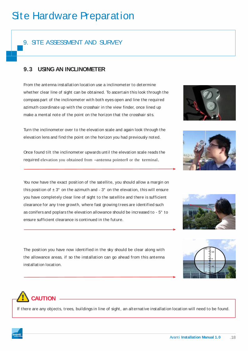
9.3 USING AN INCLINOMETER
From the antenna installation location use a inclinometer to determine
whether clear line of sight can be obtained. To ascertain this look through the
compass part of the inclinometer with both eyes open and line the required
azimuth coordinate up with the crosshair in the view finder, once lined up
make a mental note of the point on the horizon that the crosshair sits.
Turn the inclinometer over to the elevation scale and again look through the
elevation lens and find the point on the horizon you had previously noted.
Once found tilt the inclinometer upwards until the elevation scale reads the
required elevation you obtained from ―antenna pointer‖ or the terminal.
You now have the exact position of the satellite, you should allow a margin on
this position of ± 3° on the azimuth and – 3° on the elevation, this will ensure
you have completely clear line of sight to the satellite and there is sufficient
clearance for any tree growth, where fast growing trees are identified such
as conifers and poplars the elevation allowance should be increased to - 5° to
ensure sufficient clearance is continued in the future.
The position you have now identified in the sky should be clear along with
the allowance areas, if so the installation can go ahead from this antenna
installation location.
CAUTION
If there are any objects, trees, buildings in line of sight, an alternative installation location will need to be found.

Site Hardware Preparation
.19 Avanti Installation Manual 1.0
9. SITE ASSESSMENT AND SURVEY
9.4 USING A COMPASS
Compass Needle:
This arrow will always point to the Magnetic North.
This will be outlined later in more detail. Often the
compass needle is painted red so you do not mistake
the north arrow for the south arrow.
Heading Arrow:
This arrow is fixed on the base plate and it should
point in the direction that you need to look at. So
when you hold a navigation compass, always make
sure this arrow is pointed towards your destination.
i.e. The satellite.
Turntable Housing:
This top part of the Compass holds the basic
directions (north, east, south, andwest) and the
degrees. As we will see later on, this housing is
turntable so you can adjust your bearing to the
magnetic north.
Base Plate and Grip:
The base plate often has a ruler that can be used in
combination with your topographical map for
determining distances and triangulating your position.
The end is often shaped to form a palm grip with the
Heading Arrow pointing in the direction that you are
going.

Site Hardware Preparation
.20 Avanti Installation Manual 1.0
9. SITE ASSESSMENT AND SURVEY
Taking a bearing
Using a website such as
www.antennapointer.com you can
find out what the azimuth and
elevation requirements are for
finding your satellite, remember
to input the area where your
installation is taking place so you
obtain the correct details.
y The Azimuth you will need is magnetic as your compass is magnetic.
y Once you know what azimuth your satellite lies on, you can rotate the
housing so that bearing lies straight with the heading arrow (the image
below shows a bearing directly south)
y Position yourself with the compass held out in front of you and rotate
yourself until the red compass needle is in line with the red North, the
heading arrow now shows your azimuth to your satellite. You now know
where your Line of Sight lies on its azimuth.

Site Hardware Preparation
.21 Avanti Installation Manual 1.0
9. SITE ASSESSMENT AND SURVEY
9.5 USING THE GARMIN GPS METER
For the satellite broadband installation to work correctly and to enable the completion of the system auto
commission, an accurate site location needs to be identified . To do this we will use the Garmin Gps meter as
described below, once the site location has been identified the coordinates should be stored for later use.
1. Find space without too many obstructions
around, i.e. large trees, buildings etc.
2. Switch on GPS meter power button; it will
now search for satellites.
3. Once satellites have been found, the
following will be displayed.
4. Now press page button 4 times until
following is displayed and select ―mark‖
POWER
PAGE
ENTER
5. Now press ―enter‖ button once, the following
will be displayed press the ―enter‖ button
again to store the information.
You now have GPS coordinates shown at bottom of meter stored on your meter. To recover these scroll to the
waypoints option press ―enter ―then ―enter‖ again and scroll to the last entry and press enter again, these are
the coordinates you stored for this site .

Site Hardware Preparation
.22 Avanti Installation Manual 1.0
9. SITE ASSESSMENT AND SURVEY
9.6 TERMINAL LOCATION
The satellite terminal modem needs to be located within 2 meters of the customers Pc and within 2 meters of a
240 volt mains socket. This location should be discussed with the customer whilst keeping the following in mind.
1. Try to locate near to an external wall to minimize internal cabling, as black twin-sat cable is unsightly and
does not route easily over doorways etc.
2. The terminal must be easily accessible, for re-booting, future testing, troubleshooting etc.
3. Ensure there is adequate ventilation for the terminal.
4. If customer intends to set up a wireless network, try to locate terminal where you can achieve good wireless
coverage throughout the premises, however remember we are not responsible for this type of connection and
the customer may be asked to test their connection from this point if they have any problems (not very easy
with a desktop pc).
9.7 CABLING REQUIREMENTS
1. During survey the cable route should be discussed and agreed with the customer.
2. Cables should be surface mounted to external walls, fixed with twin cable clips.
3. Cables can be fixed behind vertical downpipes by using cable ties.
4. Cable entry point should be through a solid external wall.
CAUTION
No cables should be run horizontally at height, due to H & S restrictions. Cables should be dropped vertically, then
run horizontally at a safe height for the engineer without the use of ladders. Under no circumstances should cables
be run horizontally at height for purely aesthetic reasons.
DANGER
No Cable should not be attached or secured within 3‖ of mains cables, this can result in dangerous voltages
being introduced to the RF cable.
Site Hardware Preparation
.23 Avanti Installation Manual 1.0
9. SITE ASSESSMENT AND SURVEY
If customer wishes cable to be routed through loft space, it must be safe to do so.
CAUTION
o There should be adequate fixed lighting (not a torch)
o The loft should be boarded / floored and there should be no hazardous substances present, pre 1980
roof spaces should be avoided as these could contain asbestos.
o There should be a fixed means of access to the roof space i.e. suitable loft ladder.
o If customer wishes cable to be routed under floor, they must provide safe and easy access to do
so, there should be a minimum of 1 meter head clearance with no exposed mains services through
the purposed cable route.
o If customer wishes cabling to be installed behind walls, in the cavity etc, this will only be undertaken
if customer has previously installed a sufficient draw wire, and it is safe to do so.

Site Hardware Preparation
.24 Avanti Installation Manual 1.0
10. BRACKET SELECTION AND INSTALLATION
Now we have determined where the antenna is to be mounted, the routing for the RF cable and the location
of the terminal with agreement of the customer, the risk assessment and method statement can be completed
either electronically via AFA or manually on the correct documents supplied. Once this has been done we can
move on to the installation.
Bracket Types and Selection
There are five bracket installation methods available suitable for all mounting scenarios of the antenna.
Short ―L‖ bracket
suitable for mounting the antenna to a
south/west wall.
Long ―L‖ bracket
suitable for mounting south or west facing wall
where the angle of the antenna will require
further clearance from the wall.
Site Hardware Preparation
.25 Avanti Installation Manual 1.0
10. BRACKET SELECTION AND INSTALLATION
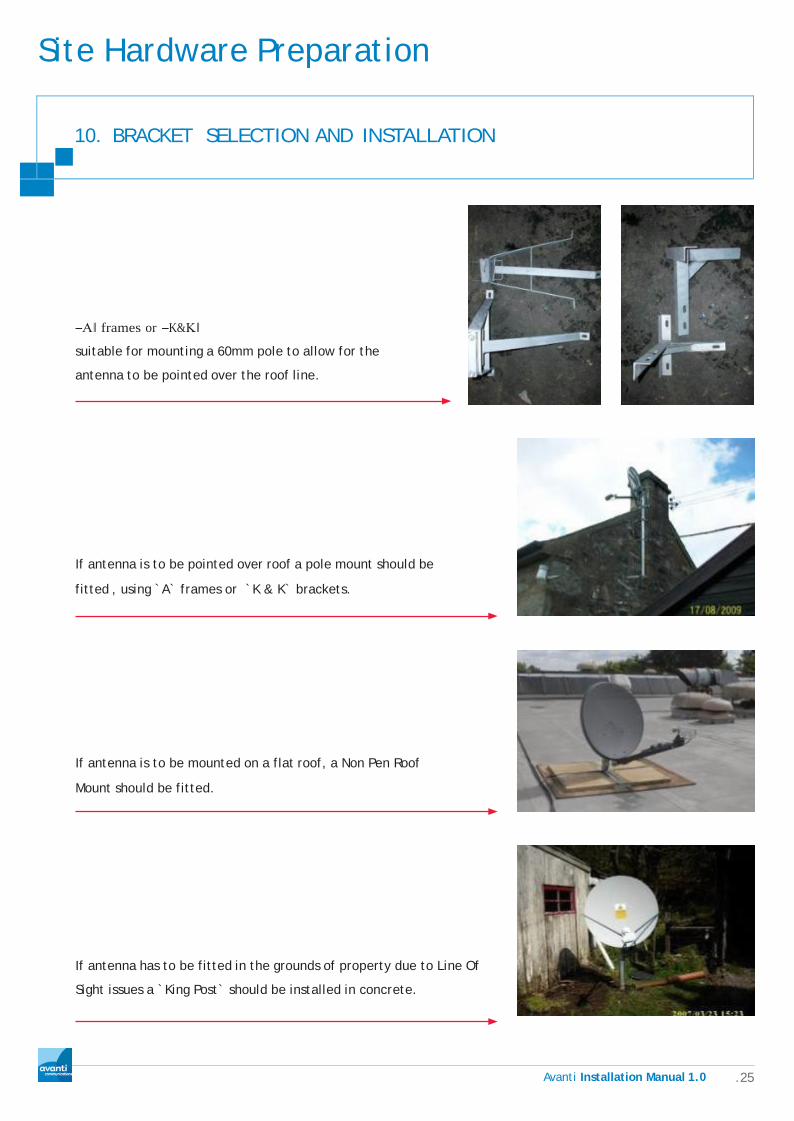
―A‖ frames or ―K&K‖
suitable for mounting a 60mm pole to allow for the
antenna to be pointed over the roof line.
If antenna is to be pointed over roof a pole mount should be
fitted , using `A` frames or `K & K` brackets.
If antenna is to be mounted on a flat roof, a Non Pen Roof
Mount should be fitted.
If antenna has to be fitted in the grounds of property due to Line Of
Sight issues a `King Post` should be installed in concrete.

Site Hardware Preparation
.26 Avanti Installation Manual 1.0
10. BRACKET SELECTION AND INSTALLATION
10.1 INSTALLATION OF STANDARD „L‟ BRACKET
CAUTION
Erect ladders safely at chosen antenna mounting location and secure, deploy all safety system required to meet
risk assessment.
1. At chosen bracket location drill one 16mm hole to depth of 75 mm,
for Rawlbolt.
2. Install the Rawl-bolt, fully tighten then remove bolt leaving the
sleeve in place
3. Fit Bracket and tighten bolt just enough to leave some movement.
4. Using a magnetic spirit level, ensure mast is plumb and mark other
3 holes
5. Move bracket aside and drill other 3 holes
to depth of 75mm.
6. Loosely fit the remaining 3 Rawlbolts, check
again to make sure bracket is level, adjust
if necessary then tighten as far as possible
without damaging wall.

Site Hardware Preparation
.27 Avanti Installation Manual 1.0
10. BRACKET SELECTION AND INSTALLATION
10.2 INSTALLATION OF POLE MOUNT ON “A” FRAMES OR “K&K” BRACKETS
CAUTION
o Erect ladders safely at chosen antenna mounting location and secure, deploy all safety system
required to meet risk assessment.
o Choose appropriate bracketry, ensure the standoff of the bracket provides sufficient clearance for leaves, gutters etc.
o Allow a minimum of 50cm from all wall edges.
1. Drill 1 x 16mm hole to depth of 75mm
2. Insert 16mm Raw bolt, fully tighten, then remove the bolt
3. Fit bracket using the bolt just removed (hand tight), place a
level across the bracket and mark the other two holes

Site Hardware Preparation
.28 Avanti Installation Manual 1.0
10. BRACKET SELECTION AND INSTALLATION
4. Turn the bracket clear of the marks
5. Drill these two holes to a depth of 75mm
6. Insert two bolts to these holes and fully tighten then remove
7. Turn bracket back into position and fit the remaining bolts,
check level and fully tighten
8. Slide a 60mm pole through the u-bolt / universal clamp until
the top of the pole is at the height required for mounting the
antenna and tighten in position.
9. Slide the second bracket onto the base of the pole, hand
tighten the u-bolt / universal clamp
10. Place a magnetic level onto the pole and adjust until
plumb, mark the holes
Site Hardware Preparation
.29 Avanti Installation Manual 1.0
10. BRACKET SELECTION AND INSTALLATION
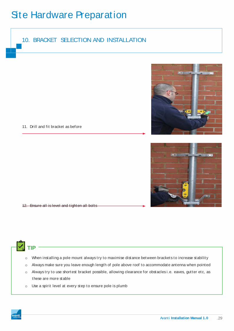
11. Drill and fit bracket as before
12. Ensure all is level and tighten all bolts
TIP
o When installing a pole mount always try to maximise distance between brackets to increase stability
o Always make sure you leave enough length of pole above roof to accommodate antenna when pointed
o Always try to use shortest bracket possible, allowing clearance for obstacles i.e. eaves, gutter etc, as
these are more stable
o Use a spirit level at every step to ensure pole is plumb

Site Hardware Preparation
.30 Avanti Installation Manual 1.0
10. BRACKET SELECTION AND INSTALLATION
10.3 INSTALLATION OF “NON-PEN” MOUNT
In the event that none of the property walls are suitable for mounting the antenna other options should be
considered. Where the building has a flat roof or a patio area a ―NPRM‖ ―Non-penetrating roof mount‖ can be fitted.
CAUTION
• Make sure roof is able to take the weight of all equipment
• Ensure there is a safe access route
• Choose best site for NPRM, ensuring clear Line Of Sight
• Ensure there is a safe method of transferring all equipment to antenna position
1. Place a 1220mm x 1220mm piece of ¼‖ marine plywood on the roof to protect the roofing materials
and evenly distribute the weight.
2. Assemble NPRM frame and place in position on top of plywood.
3. Fit 4 600mm x 600mm x 60mm paving slabs into the frame, and make sure it is stable with no
movement or wobble.
TIP
Don‘t fully tighten the two support braces until the weight of the antenna is on the mount, this will ensure the base sits flush and level with the ground.

Site Hardware Preparation
.31 Avanti Installation Manual 1.0
10. BRACKET SELECTION AND INSTALLATION
10.4 INSTALLATION OF “KING POST”
This type of installation should only be undertaken where it is impossible to achieve Line Of Sight by using
standard wall mount. This option may be chargeable to the customer so before this option is discussed
with the customer you should consult your line manager for further information as this would be classed
as a non-standard installation. This option is not to be used for purely cosmetic reasons, where a customer
wants this type of installation for cosmetic only reasons there will be an additional charge.
After discussion with customer, choose best site for `king post` installation, trying to keep cable length to
a minimum and ensuring a clear line of sight is achievable, consideration needs to be given to obstacles
that may pass in front of the antenna i.e. traffic on a road or vehicles that may be parked in this area.
CAUTION
The area around the antenna site will require fencing off to prevent
live stock accessing and damaging the antenna, also to ensure a safe
distance is maintained from the radiated RF transmission while the
system in use.
CAUTION
Before any digging takes place ensure that there are no mains services in the area you will be working in i.e.
Electricity, gas, or water. If any of these are suspected then no work should be completed without a full survey
being completed.

Site Hardware Preparation
.32 Avanti Installation Manual 1.0
10. BRACKET SELECTION AND INSTALLATION
1. Ensure ground is stable enough to support the `king post` i.e. not
boggy etc
2. Using auger or a post spade dig hole around 30cm in diameter and
90cm in depth.
3. Cut the 60mm pole to a length that keeps the antenna as low as
possible but allows clear line of site (remember the fence)
4. Fit two universal clamps to bottom of pole and fully tighten, this is
to stop the pole from `spinning` in the concrete once cured
5. Fill the base of the hole with dry postcrete to a depth of 6cm this will seal the base of the post once set
6. Lower the end of the pole with the universal clamps down into the hole
7. Fit a post level to the top of the pole
8. Use rapid set postcrete and or a hardener / accelerator
9. Follow the instructions supplied with the postcrete and fill the hole to the top
10. Add more water, and postcrete as necessary, and `tamp` with stick to remove
trapped air
11. Ensure your ‗king post‘ is plumb in all directions
12. Level again and hold in position until mixture cures enough to hold on its own
13. Complete all other works, giving postcrete time to set
14. Rapid set postcrete should achieve its working strength in around 30 minutes depending on the
temperature and climate; however care should be taken when mounting and aligning the antenna to
prevent loosening of the post.
• Green WF125 UG cable
should be used when cable
is to be buried, if using
this cable ensure that
proper Webro WF125 `F`
connectors are fitted

Site Hardware Preparation
.33 Avanti Installation Manual 1.0
11. PRODELIN MODEL AN8-074P .74M ANTENNA ASSEMBLY
11.1 COMPONENTS
The main components of the antenna kit are:
• Az/El mount assembly
• Reflector bracket and attachment disk
• Antenna reflector
• Feed support arm
• Radio assembly
• Feed horn and collar
• Related components
ANTENNA KIT COMPONENTS
11.2 AZ/EL MOUNT ASSEMBLY
The Az/El mount assembly, shown in Figure
3, consists of the Az/El canister, the elevation
scale, and the azimuth and elevation
adjustment tools.
The Az/El canister supports the antenna and
secures it to the mast. The elevation scale is
used to measure the angle of antenna
elevation. The azimuth and elevation
adjustment tools are used to finely adjust the
azimuth and elevation of the reflector during
antenna pointing.
ELEVATION SCALE
AZIMUTH ADJUSTMENT
ELEVATION ADJUSTMENT
CANISTER
FIGURE 3
Az/El mount assembly

Site Hardware Preparation
.34 Avanti Installation Manual 1.0
11. PRODELIN MODEL AN8-074P .74M ANTENNA ASSEMBLY
The reflector bracket shown in Figure 4 supports the antenna
reflector and enables the reflector to rotate so that it can
be adjusted for proper tilt. The reflector bracket attaches to
antenna at the Az/El mount assembly.
FIGURE 4
Reflector bracket
The antenna reflector shown in Figure 5 focuses the transmitted and
received RF signals. It attaches to the reflector bracket.
FIGURE 5
ANTENNA REFLECTOR
CAUTION
To avoid damage to the antenna reflector, handle it with care. After assembly, do not use the reflector to rotate
the antenna.
11.3 FEED SUPPORT ARM
Figure 6 shows the feed support
arm. The feed support arm supports
the radio assembly and feed horn.
It attaches to the reflector bracket.
FIGURE 6
Feed support arm

Site Hardware Preparation
.35 Avanti Installation Manual 1.0
11. PRODELIN MODEL AN8-074P .74M ANTENNA ASSEMBLY
11.4 RADIO ASSEMBLY
The radio assembly shown in Figure 7 consists
of the radio transmitter, low noise block
converter (LNB), transmit/receive isolation
assembly (TRIA), and polarizer waveguide.
FIGURE 7
Radio assembly
11.5 FEED HORN AND COLLAR
The elliptical feed horn, shown in Figure 8, attaches to the
polarizer waveguide on the radio assembly by way of the
two-piece collar. The feed horn gathers the reflected signal
from the antenna reflector and channels it toward the LNB.
FIGURE 8
Feed horn and collar
CAUTION
• Do not remove the protective packing material from the feed horn window until installation of the radio
assembly is complete.
• Do not attempt to remove the feed horn window at any time. Be careful not to damage the feed horn window.
• Do not touch the plastic film that covers the window.
Site Hardware Preparation
.36 Avanti Installation Manual 1.0
11. PRODELIN MODEL AN8-074P .74M ANTENNA ASSEMBLY
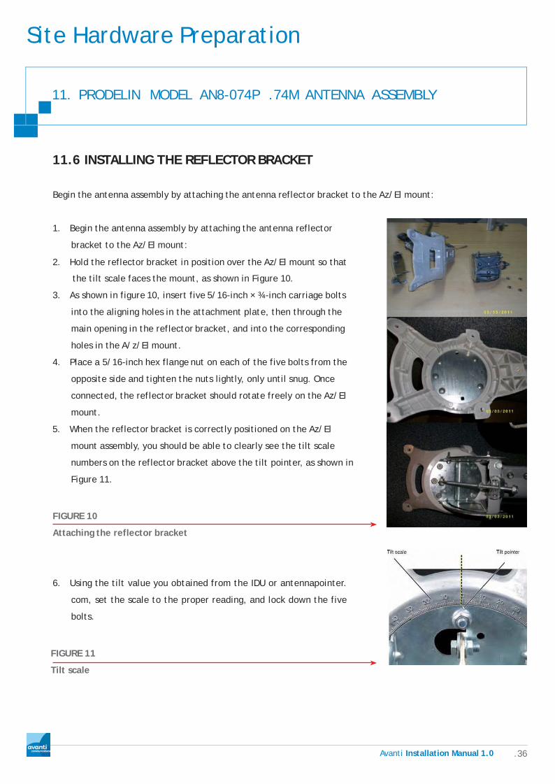
11.6 INSTALLING THE REFLECTOR BRACKET
Begin the antenna assembly by attaching the antenna reflector bracket to the Az/El mount:
1. Begin the antenna assembly by attaching the antenna reflector
bracket to the Az/El mount:
2. Hold the reflector bracket in position over the Az/El mount so that
the tilt scale faces the mount, as shown in Figure 10.
3. As shown in figure 10, insert five 5/16-inch × ¾-inch carriage bolts
into the aligning holes in the attachment plate, then through the
main opening in the reflector bracket, and into the corresponding
holes in the A/z/El mount.
4. Place a 5/16-inch hex flange nut on each of the five bolts from the
opposite side and tighten the nuts lightly, only until snug. Once
connected, the reflector bracket should rotate freely on the Az/El
mount.
5. When the reflector bracket is correctly positioned on the Az/El
mount assembly, you should be able to clearly see the tilt scale
numbers on the reflector bracket above the tilt pointer, as shown in
Figure 11.
FIGURE 10
Attaching the reflector bracket
6. Using the tilt value you obtained from the IDU or antennapointer.
com, set the scale to the proper reading, and lock down the five
bolts.
FIGURE 11
Tilt scale

Site Hardware Preparation
.37 Avanti Installation Manual 1.0
11. PRODELIN MODEL AN8-074P .74M ANTENNA ASSEMBLY
11.7 INSTALLING THE ANTENNA REFLECTOR BRACKET
To attach the antenna reflector to the reflector bracket:
1. Hold the reflector against the reflector bracket so
that the hole for the Phillips head screw is nearest
the bottom, as shown in Figure 12
2. Insert four carriage bolts (5/16-inch × ¾-inch)
into the holes in the reflector and through the
corresponding holes in the reflector bracket, as
shown in the illustration.
FIGURE 12
Attaching the antenna reflector
3. Insert the ¼-inch Phillips head screw through the hole near the bottom of the reflector and into the
corresponding hole in the reflector bracket arm
4. using a Phillips head screwdriver, tighten the ¼-inch screw
5. From the back of the reflector bracket, secure the four bolts with four ½-inch hex flange nuts and fully
tighten
Note: Ensure that the carriage bolts are firmly seated before tightening the nuts

Site Hardware Preparation
.38 Avanti Installation Manual 1.0
11. PRODELIN MODEL AN8-074P .74M ANTENNA ASSEMBLY
11.8 Installing the feed support arm
To install the feed support arm:
1. Insert the feed support arm into the housing at the
bottom of the reflector bracket, as shown in Figure 13
FIGURE 13
ATTACHING THE FEED SUPPORT ARM TO THE TAILPIECE
2. Insert two ¼-inch × 1¾-inch bolts down through the tailpiece into the feed support arm
3. Place one flat washer, lock washer, and hex nut onto each bolt and tighten to 5 ft-lb of torque
CAUTION
5 ft/lb Maximum, more than this will cause damage to the mounting bracket
11.9 INSTALLING THE RADIO ASSEMBLY
To mount the radio assembly to the feed support arm:
1. Insert a single 5/16-inch × 1¾-inch bolt, with flat washer
and lock washer up through the feed support arm from
underneath
2. Position the long adapter bracket on the feed support
arm so that the bolt fits through the hole
3. Position the feed horn support bracket above the long
adapter bracket on the feed support arm as shown in
Figure 14
FIGURE 14
Positioning the radio and feed horn brackets
Site Hardware Preparation
.39 Avanti Installation Manual 1.0
11. PRODELIN MODEL AN8-074P .74M ANTENNA ASSEMBLY
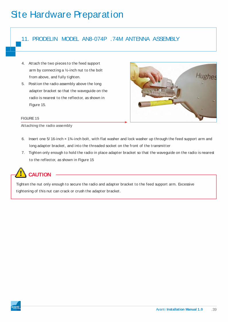
4. Attach the two pieces to the feed support
arm by connecting a ½-inch nut to the bolt
from above, and fully tighten.
5. Position the radio assembly above the long
adapter bracket so that the waveguide on the
radio is nearest to the reflector, as shown in
Figure 15.
FIGURE 15
Attaching the radio assembly
6. Insert one 5/16-inch × 1¾-inch bolt, with flat washer and lock washer up through the feed support arm and
long adapter bracket, and into the threaded socket on the front of the transmitter
7. Tighten only enough to hold the radio in place adapter bracket so that the waveguide on the radio is nearest
to the reflector, as shown in Figure 15
CAUTION
Tighten the nut only enough to secure the radio and adapter bracket to the feed support arm. Excessive
tightening of this nut can crack or crush the adapter bracket.

Site Hardware Preparation
Ava n ti Installation Manual1.0 .40
11. PRODELIN MODEL AN8-074P .74M ANTENNA ASSEMBLY
8. Place the short adapter bracket in position near the end
of the feed support arm and lower the radio onto it as
shown in Figure 16
9. Insert one 5/16-inch x 1:y,j-inch bolt, with flat washer
and lock washer, up through the feed support arm and
the short adapter bracket, into the threaded socket at
the rear of the transmitter
10. Tighten the bolt to secure the adapter bracket and
radio to the feed support arm. Tighten only until snug.
FIGURE 16
Securing the rear of the radio assembly
Tighten the nut only enough to secure the radio and adapter bracket to the feed support arm. Excessive
tightening of this nut can crack or crush the adapter bracket.

Site Hardware Preparation
Ava n ti Installation Manual1.0 .41
11. PRODELIN MODEL AN8-074P .74M ANTENNA ASSEMBLY
11.10 ADJUSTING TRANSMIT CIRCULAR POLARIZATION
(TRANSMIT POLARIZATION)
It may be necessary for you to reposition the polarizer waveguide on the radio assembly to set the proper
polarization between the radio transmitter and the antenna reflector. Before proceeding, check the
installation reference sheet to determine whether the installation calls for left-hand circular polarization
(LHCP) or right-hand circular polarization (RHCP). This is transmit polarization not receive.
Once you determine which polarization setting
is required, check the position of the polarizer
waveguide on the radio to determine whether
an adjustment is necessary. From the rear of
the radio, looking toward the reflector, you
can easily determine whether the polarizer is
currently set for LHCP or RHCP by the way it
leans. (See Figure 17.)
FIGURE 17
DETERMINING THE POLARIZATION SETTING

Site Hardware Preparation
.42 Avanti Installation Manual 1.0
11. PRODELIN MODEL AN8-074P .74M ANTENNA ASSEMBLY
To reposition the polarizer
1. Remove the two-piece polarizer collar by loosening and
removing the two Allen screws that hold it together
2. Separate the polarizer from the TRIA and rotate it one
quarter turn (clockwise for LHCP or counter-clockwise for
RHCP), until the appropriate notch lines up with the key
on the end of the TRIA. As shown in Figure 18, the LHCP
FIGURE 18
Adjusting circular polarization (collar removed)
After making the adjustment, reseat the waveguide with the TRIA and reassemble the collar as follows:
3. Fit the two halves of the collar around the waveguide as shown in Figure 19 so that the notches in the collar
come together around the ridge formed at the waveguide seam. When properly aligned, the seam formed by
the two halves of the collar will line up with the seam on the waveguide
4. Reinsert the two Allen screws into the
collar and tighten to secure the polarizer
in place. Be sure to tighten the collar
completely notch is adjacent to the L
on the polarizer and the RHCP notch is
adjacent to the R on the polarizer)
FIGURE 19
Securing the waveguide collar
CAUTION
You must assemble the collar exactly as described above and as shown in Figure 19. Failure to do so could allow
moisture to accumulate inside the TRIA, causing damage to the radio.

Site Hardware Preparation
.43 Avanti Installation Manual 1.0
11. PRODELIN MODEL AN8-074P .74M ANTENNA ASSEMBLY
11.11 INSTALLING THE FEED HORN
To attach the feed horn to the radio assembly:
1. Remove and discard the protective seal from the polarizer on the radio assembly (shown in Figure 20)
CAUTION
• Do not remove the protective packing material from the feed horn window until installation of the radio
assembly is complete
• Do not attempt to remove the feed horn window at any time
• Be careful not to damage the feed horn window
• Do not touch the plastic film that covers the window
FIGURE 20
Remove the protective seal
2. Remove the dust cap from the stem of the feed horn
and insert the O-ring into the groove inside the stem as
shown in Figure 21.
FIGURE 21
Insert O-ring

Site Hardware Preparation
.44 Avanti Installation Manual 1.0
11. PRODELIN MODEL AN8-074P .74M ANTENNA ASSEMBLY
3. Place the feed horn on the feed horn support bracket so
that the holes on either side of the feed horn fit into the
corresponding pins on the bracket, as shown in Figure 22.
FIGURE 22
Place the feed horn on the adapter bracket
4. Position the radio such that the tip of the polarizer waveguide fits against the stem of the feed horn,
then fit the two halves of the feed horn collar around the ridge at the point where the feed horn
meets the waveguide, as shown in Figure 23. When properly aligned, the seam formed by the two
halves of the collar will line up with the seam on the waveguide as shown in the figure 23 below.
FIGURE 23
Aligning the collar on the waveguide
CAUTION
You must assemble the collar exactly as described above and as shown in Figure 19. Failure to do so could allow
moisture to accumulate inside the TRIA, causing damage to the radio.
5. Insert two Allen screws into the collar and tighten to secure the feed horn in place.
6. Insert the final two mounting screws onto either side of the feed horn and secure it to the feed horn
support bracket using a ¼-inch Phillips head screwdriver.
7. At this point, fully tighten any hardware that is not tight—however, leave nuts that are used for pointing
adjustments slightly loose or just snug.

Site Hardware Preparation
.45 Avanti Installation Manual 1.0
11. PRODELIN MODEL AN8-074P .74M ANTENNA ASSEMBLY
11.12 MOUNTING OF SELECTED ANTENNA ONTO SELECTED BRACKET
CAUTION
Erect ladder and secure, allowing safe access to bracket.
Method 1
If you feel comfortable with the weight of the antenna, carry it up ladder, completely assembled, with reflector
on your back and feed support arm over your shoulder.
1. Once you reach position of bracket, get comfortable on ladder and hook yourself on to rung with cows-tail.
2. Now remove antenna from your shoulder, turn it around and drop canister on to bracket and secure.
Method 2
3. Carry assembled Az/el mount and reflector up ladder to position of bracket.
4. Once you reach position of bracket, get comfortable on ladder and hook yourself on to rung with cows-tail.
5. Drop canister on to bracket and secure.
6. Now bring up feed support arm(s) and radio assembly and assemble in position.

Site Hardware Preparation
.46 Avanti Installation Manual 1.0
12. CABLING
Before any existing cable is connected to the new equipment the following points should be checked. If any
issues are found then the cable should be replaced.
12.1 Cable standard
Avanti user standard cable specification; WF100 shotgun and WF125. CT125green duct grade cable can be used
for Kingpost installs
1. Check the cable, type air flow cable is not acceptable for satellite
broadband installations and should be replaced with foam dielectric
type cable WF100. This is due to the nature of air flow cable types
and issues with them being easily crushed and distorted.
FIG. 2: DIFFERENT TYPES OF DIELECTRIC
Top left, foam dielectric used in type B cable Top
left, semi-airspaced used in type D cable Bottom
left, semi-airspaced used in type C cable Bottom
right, semi-airspaced used in type A cable
2. The cable should be marked with its type WF100, CT100, WF125 and CT125 these are acceptable. These
cable should be Tri or Quad shielded
3. Cable selection: The cable used for all installs, service calls and migrations should be shotgun WF100 unless
otherwise stated or in cases where the cable runs underground in which case CAI Approved underground
WF125 cable should be used

Site Hardware Preparation
.47 Avanti Installation Manual 1.0
12. CABLING
12.2 Bend radius
Before connecting any cables, check the existing cable for kinks,
crushing, damage and poorly formed bends. These situations result
in the cable performance being impaired resulting in poor the
performance of the broadband service you are installing.
CABLE BEND
CAUTION
Bend Radius: Which is measured to the inside curvature is the minimum radius one can bend a cable without
kinking it, damaging it, or shortening its life. Bends in the cable must always be kept to a minimum.
12.3 Interference considerations
When checking or running cables pay attention to possible sources of RF interference as theses will interfere
with the broadband connection.
CAUTION
• Avoid running cables alongside High Voltage mains cabling especially external three phase cables. There
should be a minimum of 10cm between the cables, failure to follow this guideline can result in interference,
however can also cause the Rx /Tx cable of the installation being induced with a high voltage which can give
a nasty shock and also damage satellite and computer equipment
• Try to avoid running near fluorescent lighting units
• Lift/elevator or other electric motors and generators
• Avoid other transmission sources such as two way radios and cordless phones
Site Hardware Preparation
.48 Avanti Installation Manual 1.0
12. CABLING
12.4 Maximum Cable Lengths
The ‗standard installation‘ will have up to 30 meters of cable however, ‗non–standard‘ installations could be
anything up to the maximum for the cable type. Installed cables should be kept to a minimum length whenever
possible.
o WF100 / CT100 maximum cable length deployed 125 meters
o WF125 / CT125 maximum cable length deployed 250 meters
12.5 Cable entry point requirements
CAUTION
• Always check for services with an appropriate tester before drilling commences, however these cannot be
relied upon fully as they are not always 100% accurate
• Always drill from inside the property to the outside (NEVER THE OTHER WAY AROUND)
• Drill from just above skirting board level where possible with a slight downward angle, this is to lessen the
possibility of water migrating into the hole
• Avoid drilling near any mains power outlet or switch
• Remember to seal the hole with a grommet on the inside and silicone and blast plate on the exterior. (refer
below to item 10)
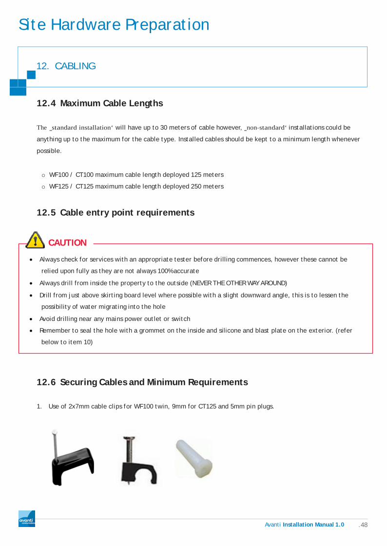
12.6 Securing Cables and Minimum Requirements
1. Use of 2x7mm cable clips for WF100 twin, 9mm for CT125 and 5mm pin plugs.

Site Hardware Preparation
.49 Avanti Installation Manual 1.0
12. CABLING
2. Cables should be secured to wall with cable clips, on
vertical runs these should be a maximum of 50cm apart
and on the horizontal 30cm (or hammer length) apart.
Cables can be secured behind downpipes etc, using
cable ties
3. Where the substrate is too hard, i.e. Granite or other stone the use of pin plugs will be required. In this
scenario you will need to drill a 5mm hole first, insert pin plug then proceed using correct cable clip
4. If the cable needs to be run across a flat roof, fit a 50mmx25mm wooden batten and attach the cable to this
5. Cable should be fixed to the antenna arm using cable ties, the cable should not be fed through the support arm
12.7 DRIP AND SERVICE LOOP REQUIREMENTS
1. At cable entry point always leave drip loop, this is to
lessen possibility water migrating into hole
2. A 1 meter service loop should be positioned at the
rear of the antenna and neatly coiled without twists

Site Hardware Preparation
.50 Avanti Installation Manual 1.0
12. CABLING
12.8 CONDUIT FOR UNDERGROUND CABLE RUNS
1. If cable has to be buried, it should be placed inside conduit for its full length for added protection
2. The duct must be present at least 10cm above ground at both sides of the cable run, it must also be sealed
with silicone
3. An alternate option is to use direct burial cable as specified In section 10.1
12.9 WATERPROOFING - BLAST PLATES AND GROMMETS
1. The cable should always enter from underneath the entry point
2. At the external cable entry point, seal the hole with silicone sealant
FILL ENTRY POINT WITH SILICON
3. A plastic blast plate should then be fitted, use a colour that‘ fits in with
the render or stone colour the best
4. Using clear silicone to fix the blast plate to the wall, if this is
insufficient, a couple of nails from cable clips will hold it in place
BLAST PLATE OVER CABLE
5. At the internal entry point a plastic
grommet should be fitted to tidy up the
hole and protect the cable, this should
be tight in hole, but if not a small bit of
sealant can be used to hold it in place.
FIT A GROMMET TO THE INTERNAL HOLE
Site Hardware Preparation
.51 Avanti Installation Manual 1.0
12. CABLING
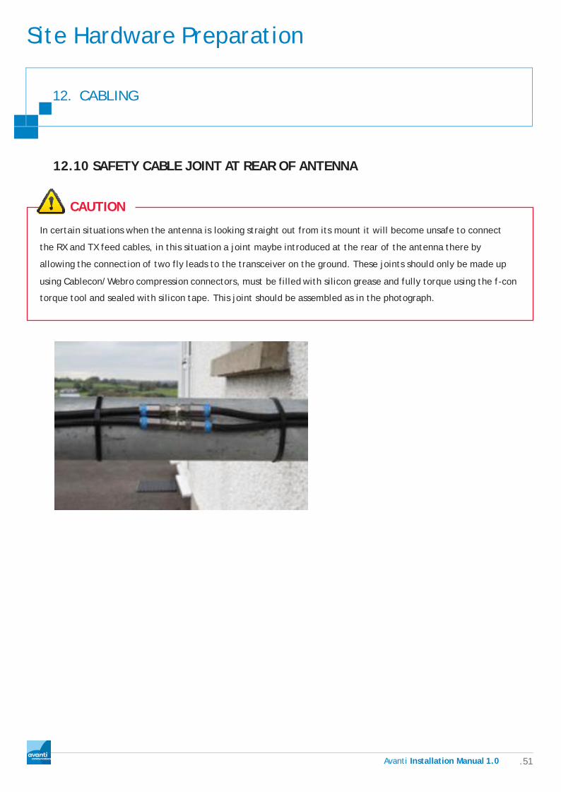
12.10 SAFETY CABLE JOINT AT REAR OF ANTENNA
CAUTION
In certain situations when the antenna is looking straight out from its mount it will become unsafe to connect
the RX and TX feed cables, in this situation a joint maybe introduced at the rear of the antenna there by
allowing the connection of two fly leads to the transceiver on the ground. These joints should only be made up
using Cablecon/Webro compression connectors, must be filled with silicon grease and fully torque using the f-con
torque tool and sealed with silicon tape. This joint should be assembled as in the photograph.

Site Hardware Preparation
.52 Avanti Installation Manual 1.0
12. CABLING
12.11 COMPRESSION CONNECTORS
12.11.1 Required tools as shown in image below:
o Side Cutters
o Cable Stripping tool
o ‗F‘ Compression tool
o ‗F‘ Insertion tool
o Cable gripper
o 11mm spanner
o 14mm spanner
o F-connector torque tools
12.11.2 Connector selection
y Avanti recommend the use of Cablecon /Webro compression connectors only
y Connectors currently in service are 5.1 for WF100 and 6.0 for WF125
y No other type of connector may be used at this time
12.11.3 Fitting Webro WF100 compression connectors
The WF100 cable uses the Cablecon 5.1 ‗F‘ connector
1. Using stripping tool, insert cable and rotate stripper
around the cable several times until cable is cut, then pull
away. Discard pieces of cable safely. Pull back braiding
around outer sheath of cable
2. Fit Cablecon/Webro compression connector onto insertion
tool and ensure a secure fit, with 11mm spanner
TIP
Put a small amount of silicon grease into the rear of the connector around the neck of the center pillar, this will
lubricate the cable as you push it into the connector and will also provide additional waterproofing.

Site Hardware Preparation
.53 Avanti Installation Manual 1.0
12. CABLING
3. Place cable gripper on cable about 2cm
below cut part of cable
4. Push connector onto cable and with a gentle force
using a push and twist action until you can see the
inner cable stinger in the hole of the insertion tool.
5. Unscrew insertion tool and ensure foam dielectric is up to the shoulder of the connector, if not repeat
above steps.
6. Place cable and connector into
compression tool and squeeze together
until ‗F‘ compresses fully.
7. Visually check the ‗F‘ connector to ensure it is fitted
properly and secure.

Site Hardware Preparation
.54 Avanti Installation Manual 1.0
12. CABLING
12.12 FITTING WEBRO WF125 COMPRESSION CONNECTORS
The WF125 cable uses the Cablecon/Webro 6.0 ‗F‘ connector; it has a centre stinger already pre-fitted. The
cable must be prepared in the same manner. The centre core of the connector will come through confirming a
good connection internally.
1. Using stripping tool, insert cable and rotate
stripper around the cable several times until
cable is cut, then pull away. Discard pieces of
cable safely. Pull back all the braiding around
outer sheath of cable.
2. Fit Cablecon/Webro compression connector
onto insertion tool and ensure a secure fit
using a 14mm spanner.
3. Place cable gripper on cable about 2cm
below cut part of cable.
TIP
Put a small amount of silicon grease into the rear of the connector around the neck of the center pillar, this will
lubricate the cable as you push it into the connector and will also provide additional waterproofing.

Site Hardware Preparation
.55 Avanti Installation Manual 1.0
12. CABLING
4. Push connector onto cable and with a gentle force using a
push and twist action until you can see the inner core in the
hole of the insertion tool.
5. Unscrew insertion tool and ensure foam dielectric is up to the shoulder of the connector, if not repeat
above steps.
6. Place cable and connector into
compression tool and squeeze
together until ‗F‘ compresses fully.
7. Check that the centre pin of the ‗F‘
connector to ensure it has pushed out as
pictured below, this means the connector
is fitted correctly.

Site Hardware Preparation
.56 Avanti Installation Manual 1.0
12. CABLING
12.13 THE SKIN EFFECT
The Skin effect is the tendency of an alternating electric current (AC) to distribute itself within a conductor so
that the current density near the surface of the conductor is greater than that at its core. That is, the electric
current tends to flow at the ―skin‖ of the conductor, at an average depth called the skin depth. The skin
effect causes the effective resistance of the conductor to increase with the frequency of the current because
much of the conductor carries little current. Skin effect is due to eddy currents set up by the AC current. At
60 Hz in copper, skin depth is about 8.5 mm. At high frequencies skin depth is much smaller.
In basic terms, the signal will be carried over the outer skin of the centre copper core, so if you used a knife
to prepare the cable and nicked the copper core, this may cause some problems to arise. Therefore to avoid
this always use the correct cable stripping tool.
12.14 WATERPROOFING REQUIREMENTS
y Cablecon 5.1 and 6.0 compression
‗F‘ connectors have been
fully tested for water ingress.
Compression ‗F‘ connectors are the
only connectors accepted by Avanti
for use on its network.
y Dielectric grease must be used at
all times.
y The 5.1 ‗F‘ connector used on
WF100 must be torque to 3.5nM or
30 in/lb. Using an 11mm or 7/16
spanner.
y The 6.0 ‗F‘ connector used on
WF125 must be torque to 3.5nM
or 30 in/lb. Using a 14mm or 9/16
spanner.
.57 Avanti Installation Manual 1.0
Terminal Commissioning And Antenna Alignment
13. TERMINAL CONNECTION
Location and connection should be straight forward during an installation however pay attention to ventilation
and surge protection.
13.1 TERMINAL LOCATION
1. Discuss terminal location preference with customer and confirm if possible.
2. Try to locate terminal as close to customers PC as possible.
3. Ensure the terminal will have adequate ventilation in the selected location.
4. Terminal must be located within a couple of meters of a 240v mains outlet.
5. If customer intends to set up a wireless network, try to locate terminal where you can achieve good
wireless coverage throughout the premises.
6. Try to locate near to an external wall to minimise internal cabling, as black twin-sat cable is unsightly and
does not route easily over doorways etc.
7. The terminal must be easily accessible, for re-booting, future testing, troubleshooting etc.
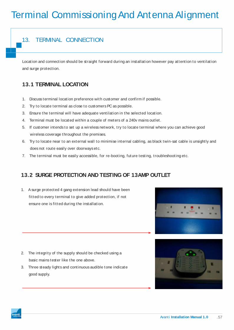
13.2 SURGE PROTECTION AND TESTING OF 13AMP OUTLET
1. A surge protected 4 gang extension lead should have been
fitted to every terminal to give added protection, if not
ensure one is fitted during the installation.
2. The integrity of the supply should be checked using a
basic mains tester like the one above.
3. Three steady lights and continuous audible tone indicate
good supply.
.58 Avanti Installation Manual 1.0
Terminal Commissioning And Antenna Alignment
13. TERMINAL CONNECTION
DANGER
If the tester shows any fault with the supply, do not connect the terminal until the customer has had the fault
resolved. Contact your line manager for further advice.
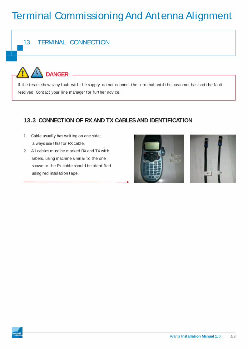
13.3 CONNECTION OF RX AND TX CABLES AND IDENTIFICATION
1. Cable usually has writing on one side;
always use this for RX cable.
2. All cables must be marked RX and TX with
labels, using machine similar to the one
shown or the Rx cable should be identified
using red insulation tape.
.59 Avanti Installation Manual 1.0
TERMINAL COMMISSIONING AND ANTENNA ALIGNMENT
14. AFA Job Synchronization.
14.1 AFA JOB SYNCHRONIZATION WITH OSS
Before any installation can be completed using the AFA the AFA software must be synchronized with the
Avanti OSS system, this will ensure the job details are available at the terminal commissioning stage.
Without these details preloaded into the AFA you will not be able to complete any installation. The
following describes how to synchronize the AFA with the OSS which must be completed BEFORE
attending site.
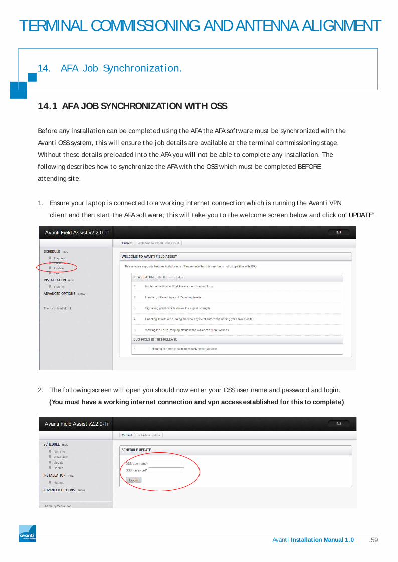
1. Ensure your laptop is connected to a working internet connection which is running the Avanti VPN
client and then start the AFA software; this will take you to the welcome screen below and click on”UPDATE”
2. The following screen will open you should now enter your OSS user name and password and login.
(You must have a working internet connection and vpn access established for this to complete)

TERMINAL COMMISSIONING AND ANTENNA ALIGNMENT
.60 Avanti Installation Manual 1.0
14. AFA Job Synchronization.
2. The login screen will show “please wait” and “updating schedule”.
3. Once the update is completed you will see the screen below.
4. You can now view and check your jobs are loaded in the AFA schedule by selecting week view or day view and then the date from the calendar, your jobs for that date will show in the schedule table as below. You can select print to print a copy of your weeks work.

TERMINAL COMMISSIONING AND ANTENNA ALIGNMENT
14. AFA Job Synchronization.
5. By clicking on the customer code in the schedule table all the details for that customer will be shown, again you can print all the customers’ details.
6. You can also select search to find a particular customer by using the search option useful if you don’t know the actual install date. Enter your customer code and click on “go” clicking on the customer code shown under “job” will show all the customer detail.
Ava n ti Installation Manual1.0 .61

TERMINAL COMMISSIONING AND ANTENNA ALIGNMENT
Ava n ti Installation Manual1.0 .62
14. AFA Job Synchronization.
7. That is the AFA / OSS sync completed and ready for you to complete your onsite installation. To exit the AFA click on exit shown below.
8. You can now attend your customer’s site address and start the installation as described in the next section.

TERMINAL COMMISSIONING AND ANTENNA ALIGNMENT
Ava n ti Installation Manual1.0 .63
14. ANTENNA ALIGNMENT METHOD
14.2 POINTING THE ANTENNA
Prerequisites
Before pointing the antenna, you must:
1. Assemble and install the antenna and radio assembly. Follow the instructions in the installation guide for
the specific antenna model you are installing.
2. Install the IDU. Follow the instructions in the installation guide for the specific IDU model you are installing.
3. Run and connect the intra-facility link (IFL) cable between:
a. The SAT OUT connector on the IDU and the transmit connector on the radio transmitter.
b. The SAT IN connector on the IDU and the receive connector on the LNB, an active two way splitter
should be fitted at the rear of the antenna to facilitate alignment using the Horizon HD-S2 meter.
CAUTION
The IDU must be powered off when you connect or disconnect the IFL cables. If power is on, you could short the
connectors and cause damage to the IDU and radio assembly.

TERMINAL COMMISSIONING AND ANTENNA ALIGNMENT
Ava n ti Installation Manual1.0 .64
14. ANTENNA ALIGNMENT METHOD
14.3 POINTING OVERVIEW
Antenna pointing is a critical part of the antenna installation process. If the antenna is not properly pointed
toward the satellite, the IDU cannot communicate with the satellite to full capacity, and performance will
be degraded. The Hughes Net system uses a narrow Ka-band beam that can be sensitive to pointing errors, so
proper and accurate antenna pointing is essential.
To point the antenna you adjust azimuth and elevation while you use the Horizon HD-S2 to measure signal
strength in a defined series of steps.

TERMINAL COMMISSIONING AND ANTENNA ALIGNMENT
Ava n ti Installation Manual1.0 .65
14. ANTENNA ALIGNMENT METHOD
14.4 ALIGNMENT AND TERMINAL CONFIGURATION
USING THE HORIZON USB S2 METER AND THE AFA
1. Fit antenna on to bracket and point it in the general direction of the satellite, tighten the canister
and elevation bolts just enough to still allow some movement.
2. Connect a test lead to the RX connection on ODU and the other end to a 2 way dc bypass active
splitter.
3. Connect the Rx cable from the IDU to the Dc bypass port on the splitter and a second fly lead between
the splitter and the input connection on meter.
4. Power on the terminal.
14.5 CONNECTING YOUR LAPTOP
1. The Laptop should be
connected directly
to terminal via a
cat5e patch lead.
2. The laptop should be
set to DHCP.
3. Laptop will be issued
an IP address
automatically via the
DHCP on the
terminal.

TERMINAL COMMISSIONING AND ANTENNA ALIGNMENT
Ava n ti Installation Manual1.0 .66
14. ANTENNA ALIGNMENT METHOD
14.6 TERMINAL PRE ALIGNMENT CONFIGURATION USING AFA SOFTWARE
Avanti Field Assist is a desktop software application that helps field engineers set up and configure Hughes
terminals on site, file installation, QA and risk assessment reports while on site. All reports and configuration
settings are stored offline and later transferred to Avanti‘s OSS system when an online connection is available.
With the terminal connected to the commissioning laptop via an Ethernet lead proceed as follows.
NOTE: Ensure you have all the cables connected at the antenna, the splitter and meter in line BEFORE you power up the terminal. Do not disconnect any leads OR Power off the terminal until the terminal is fully commissioned.
1. Power on the terminal and Start the AFA the launch screen will load. Select “Hughes” from the left menu.
2. The AFA will now ask for the customer code that you are about to install. Select the date of the install and then
your customer from the “select job” drop down. Your job details will appear as below. Click “Proceed with the job”

TERMINAL COMMISSIONING AND ANTENNA ALIGNMENT
Ava n ti Installation Manual1.0 .67
3. The AFA will now check the terminal software version and update if required (Note some versions of software require the terminal to be hard rebooted, follow the on screen messages if this is required).
3. Once the software has been upgraded and verified (The terminal will automatically reboot if upgraded) you will see the screen as below.
4. Enter the GPS settings you collect earlier, using Deg, Min and Sec format. Select the antenna size from the drop down and click “Apply”
TERMINAL COMMISSIONING AND ANTENNA ALIGNMENT
Ava n ti Installation Manual1.0 .68
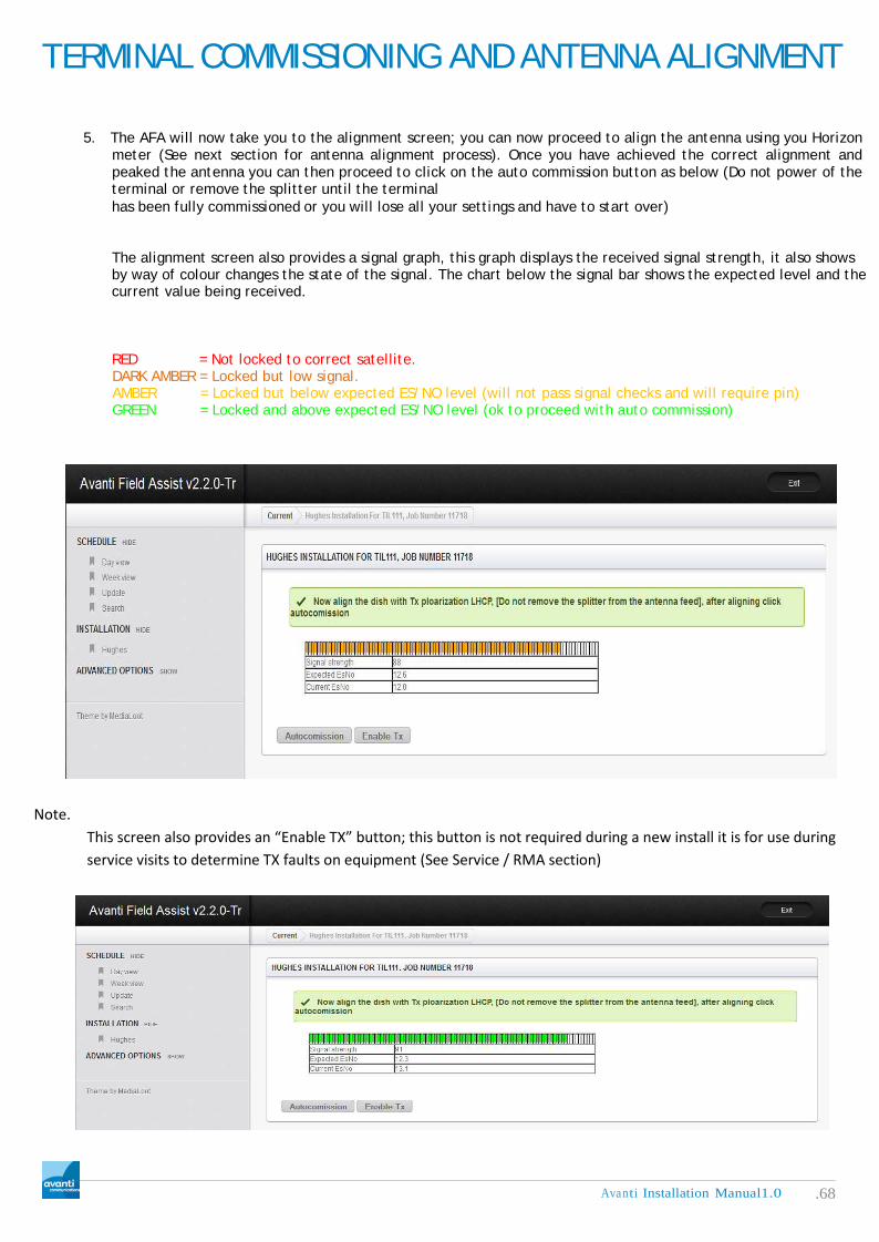
5. The AFA will now take you to the alignment screen; you can now proceed to align the antenna using you Horizon meter (See next section for antenna alignment process). Once you have achieved the correct alignment and peaked the antenna you can then proceed to click on the auto commission button as below (Do not power of the terminal or remove the splitter until the terminal has been fully commissioned or you will lose all your settings and have to start over) The alignment screen also provides a signal graph, this graph displays the received signal strength, it also shows by way of colour changes the state of the signal. The chart below the signal bar shows the expected level and the current value being received. RED = Not locked to correct satellite. DARK AMBER = Locked but low signal. AMBER = Locked but below expected ES/NO level (will not pass signal checks and will require pin) GREEN = Locked and above expected ES/NO level (ok to proceed with auto commission)
Note.
This screen also provides an “Enable TX” button; this button is not required during a new install it is for use during service visits to determine TX faults on equipment (See Service / RMA section)
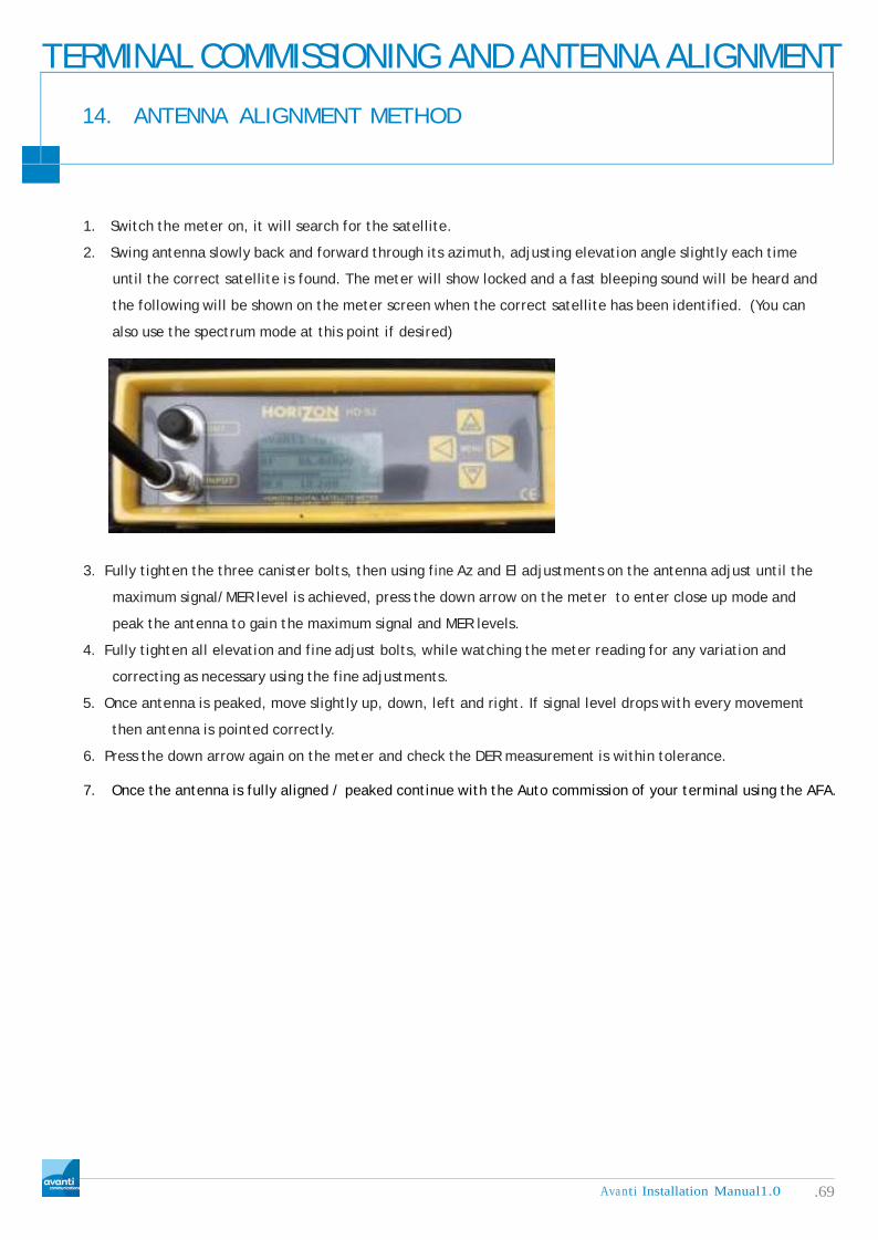
TERMINAL COMMISSIONING AND ANTENNA ALIGNMENT
Ava n ti Installation Manual1.0 .69
14. ANTENNA ALIGNMENT METHOD
1. Switch the meter on, it will search for the satellite.
2. Swing antenna slowly back and forward through its azimuth, adjusting elevation angle slightly each time
until the correct satellite is found. The meter will show locked and a fast bleeping sound will be heard and
the following will be shown on the meter screen when the correct satellite has been identified. (You can
also use the spectrum mode at this point if desired)
3. Fully tighten the three canister bolts, then using fine Az and El adjustments on the antenna adjust until the
maximum signal/MER level is achieved, press the down arrow on the meter to enter close up mode and
peak the antenna to gain the maximum signal and MER levels.
4. Fully tighten all elevation and fine adjust bolts, while watching the meter reading for any variation and
correcting as necessary using the fine adjustments.
5. Once antenna is peaked, move slightly up, down, left and right. If signal level drops with every movement
then antenna is pointed correctly.
6. Press the down arrow again on the meter and check the DER measurement is within tolerance.
7. Once the antenna is fully aligned / peaked continue with the Auto commission of your terminal using the AFA.
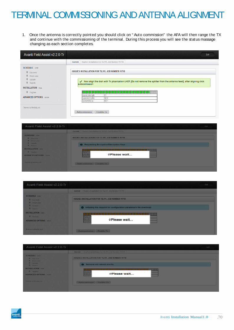
Ava n ti Installation Manual1.0 .70
TERMINAL COMMISSIONING AND ANTENNA ALIGNMENT
1. Once the antenna is correctly pointed you should click on “Auto commission” the AFA will then range the TX and continue with the commissioning of the terminal. During this process you will see the status massage changing as each section completes.

Ava n ti Installation Manual1.0 .71
TERMINAL COMMISSIONING AND ANTENNA ALIGNMENT
2. If you were unable to reach the expected ES/NO level you should recheck the antenna alignment then click the auto commission button again. On the third fail attempt you will be asked for a pin number to proceed. This pin number is only available by calling Avanti technical support on +44(0)2077498105, enter the number provided and then click on “auto commission” this will then complete as above.
3. The terminal may reboot several times during this process, once completed you will see the screen pictured below, and you should now enter your OSS Username and password and click on “Login” to complete the report and the job. At this point all browsing test and speed test should be checked and demonstrated to the customer. If your terminal is set up with a routed IP address the screen will show the settings required on your laptop network card.
4. Fill out the required fields in the reporting section as below, then click “Submit Report”
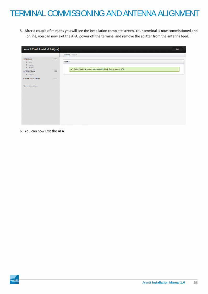
TERMINAL COMMISSIONING AND ANTENNA ALIGNMENT
.68 Avanti Installation Manual 1.0
5. After a couple of minutes you will see the installation complete screen. Your terminal is now commissioned and online; you can now exit the AFA, power off the terminal and remove the splitter from the antenna feed.
6. You can now Exit the AFA.

.69 Avanti Installation Manual 1.0
Connection Testing And Customer Reporting
16.1 BROWSING TESTS
Browsing tests are used so you can see graphically that you have a connection, your DNS is working, and to
some extent if the delay for the webpage opening is acceptable.
1. Test Pages as follows
www.google.co.uk
www.bbc.co.uk
www.cnn.com
2. Browsing should also be demonstrated to the customer
16.2 SPEED TESTS
Speed Tests are carried out so you can identify incorrect SLA, this may also help you identify any issues with
the installation.
y Avanti provide several download test files, varying in size. 1MB(1.bin), 5MB(5.bin), 10MB(10.bin) and
50MB(50.bin). You can access these files at this web site http://speedtest.avantiplc.eu/ Use your browser or WGET to test the speed.
16.3 PING TESTS
Ping is a computer network administration utility used to test the reachability of a host on an Internet Protocol
(IP) network and to measure the round-trip time for messages sent from the originating host to a destination
computer. The name comes from active sonar terminology.
1. Ping operates by sending Internet Control Message Protocol (ICMP) echo request packets to the target
host and waiting for an ICMP response. In the process it measures the time from transmission to reception
and records any packet loss. The results of the test are printed in form of a statistical summary of the
response packets received, including the minimum, maximum, and the mean round-trip times.

.70 Avanti Installation Manual 1.0
Connection Testing And Customer Reporting
16. TERMINAL TESTING AND DEMONSTRATION
2. Above you can see how ping works, on average the RTT you will probably see over a satellite connection is
500-700ms. You should also not see any packet loss.
16.4 Ping Commands
1. Ping www.awebsite.com, this will ping this website, if there is no DNS resolution you will not be able to ping.
2. Ping 74.125.230.112 this will ping an IP address, DNS is not required.
3. You can use the following switches also:
A. /t – constantly ping until interrupted
B. /n 10 – Ping 10 times, change the number for more or less
C. /l 4096 – Increase packet size, change value to required packet, shown is 4KB packet.

.71 Avanti Installation Manual 1.0
Connection Testing And Customer Reporting
17. USEFUL TOOLS
17.1 WGET
GNU Wget is a free software package for retrieving files using HTTP, HTTPS and FTP, the most widely-used
Internet protocols. It is a non-interactive command line tool, so it may easily be called from scripts, cron jobs,
terminal without X-Windows support, etc.
17.2 NETPERSEC
NetPerSec monitors and graphs your network
bandwidth usage for all or any network
interface card. An ingenious Windows system
tray icon displays a miniature bandwidth graph.
17.3 DU METER
DU Meter provides an accurate account of the
data which is flowing through your computer‘s
network connection. This real time readout
is presented in both numerical and graphical
format.
DU Meter or NetPerSec is personal preference
both work in a similar way.

Connection Testing And Customer Reporting
.81 Avanti Installation Manual 1.0
18. COMPLETING THE REPORT WITH AFA
Once testing has been completed and the broadband service has been demonstrated to the customer you are
required to complete the following steps.
18.1 AFA REPORTING REQUIREMENTS
To complete the job the report section on AFA must be completed with all relevant detail required.
Avanti recommend that certain photographs should be gathered whilst completing the
installation, this will assist when troubleshooting in the future. See next section for details of
photographic recommendations.
18.2 PHOTOGRAPHIC REPORTING RECOMMENDATIONS
1. The first photograph should be of the line of sight from the antenna. This
should be taken with the camera placed back against the antenna reflector
just above the boom arm and clearly show the transceiver in the center of
the shot.
2. The second
photograph
required is of the
antenna and its
mounting bracket
3. The third
photograph is of
the antenna in its
mounting location
showing the building
it is attached to.

Connection Testing And Customer Reporting
.82 Avanti Installation Manual 1.0
19. CLEARING SITE
Once the report has been completed and sent via AFA the customers site should be cleared.
• All tools and ladders should be removed
• Any debris should be cleaned up and disposed of in a safe manner

Connection Testing And Customer Reporting
.83 Avanti Installation Manual 1.0
20. SERVICE AND RETURN MATERIAL REQUEST (RMA)
Before returning any suspected faulty equipment to Avanti via the RMA process the following should be checked, this should be done on site during a service visit to determine that the unit is actually at fault.
1. Physical Inspection Prior to screening all returned hardware, check for physical damage and possible water ingress – minor scuffs & reasonable cosmetic damage are acceptable. Water/fluid damage, cracks & holes are treated as an immediate failure, no testing should be carried out – This type of damage is not covered under warranty.
2. Initial Testing
Connect the HN9200 to the Test PC and power up IDU, check the LED lights for indication of power present. The power LED should at least flash after 30 seconds – if not, record S/N & return to AVANTI for repair or WEEE disposal.
3. Connect to PC
Connect the CAT5 cable between your PC and the HN9200.
Note: The HN9200 auto detects the type of cables your have (X or Straight Cat5).
The HN9200’s Ip address is preset to 192.168.0.1. If your PC’s network card to set for DHCP, the HN9200 will automatically allocate you the Ip address of 192.168.0.2.It is preferred the PC has a statically assigned ip of 192.168.0.2 & a gateway of 192.168.0.1 (255.255.255.0 mask), in a lab environment this should always be the case.
At your PC, open a Command prompt
Type ipconfig <enter>
Your window should like this:
Ensure you can ping the IDU, (ping 192.168.0.1) before proceeding to the next section
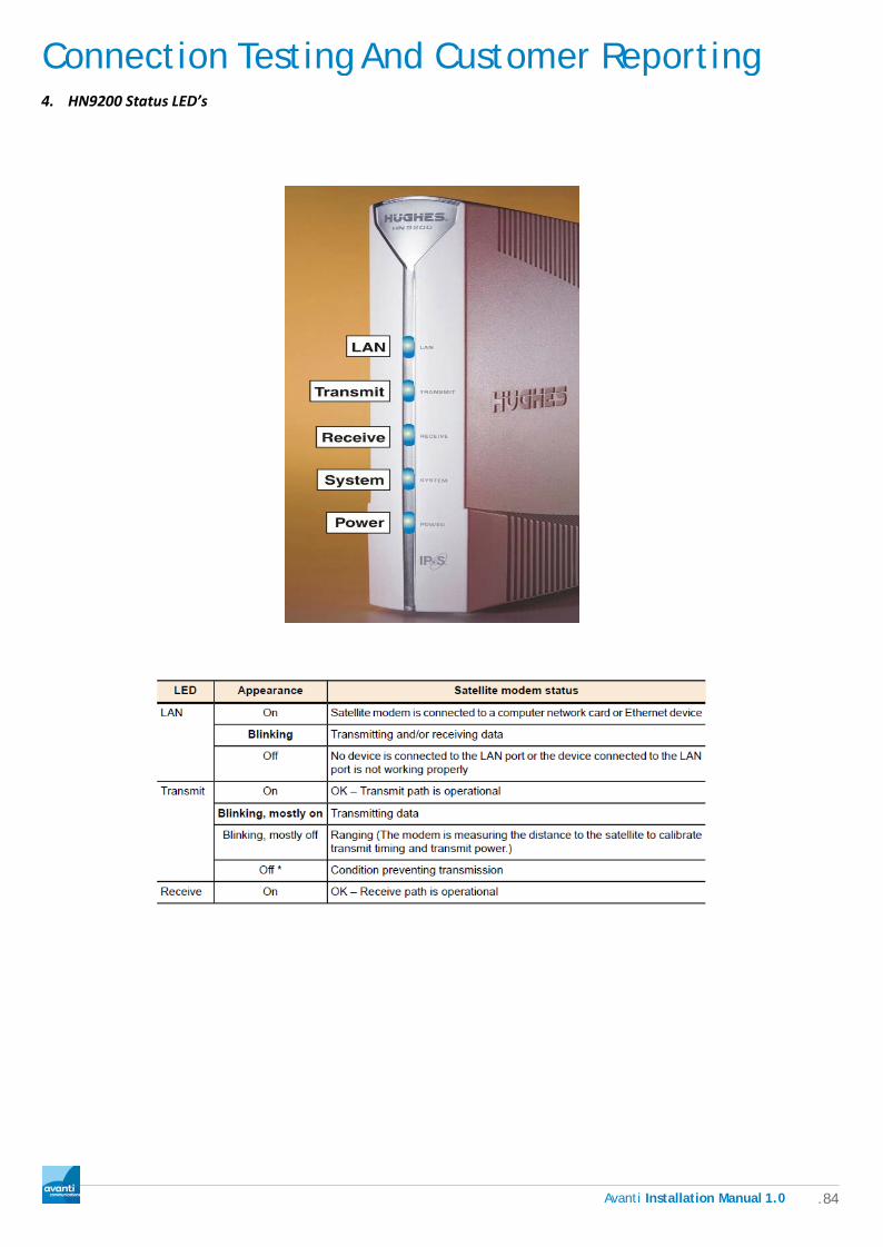
Connection Testing And Customer Reporting
.84 Avanti Installation Manual 1.0
4. HN9200 Status LED’s