Hydropower & Dam Safety Project Descriptions
19
21300 RIDGETOP CIRCLE STERLING, VA 20166 WWW.SUTRON.COM (703)406-2800 (703)406-2801 FAX [email protected] HYDROPOWER & DAM SAFETY HYDROPOWER SERVICES Inflow Monitoring for Short Term Scheduling High Hazard Dam Warning Systems Water Use Optimization Input to Real-Time Models Inflow/Outflow Monitoring Systems Compliance Monitoring Instream Flow Requirements Ramp Rates Water Rights Monitoring Water Quality Monitoring Gate Control Geotechnical Monitoring Systems HYDROPOWER CUSTOMERS PacifiCorp Florida Power & Light TVA PG&E Northeast Utilities Southern California Edison Millineum Power Bureau of Reclamation H Hatfield Hydro Thunder Bay Power So. New Hampshire Power Consumer Power US Army Corps of Engineers American Power Reliant Energy Niagara Mohawk Grant County, WA PUD EWEB PACIFICORP - CASE STUDY NORTH UMPQUA HYDROELECTRIC PROJECT, FERC PROJECT NO. 1927 Compliance with Oregon Water Resources Department (OWRD) licensing regulations by monitoring flow in the network of canals withdrawing water from the North Umpqua River and its tributaries near Toketee Lake As one of the lowest-cost hydropower producers in the U.S., Pacifi Corp generates 8,000 megawatts of energy for nearly 1.5 million customers in the Pacific Northwest. On July 19th of 2000 Pacifi Corp agreed to monitor flow in the network of canals withdrawing water from the North Umpqua River and its tributaries near Toketee Lake to assure water rights compliance. Sutron received contracts for the fi rst two phases of the project. The contract for the fi rst phase, valued at $200,412, was completed in 2001. The contract for the second phase of the project, valued at over $369,500, was awarded to Sutron in July 2002 (included with July 2002 bookings) to be completed by October 31, 2002. The contract for the third phase of the project, which will include real-time telemetry for all existing gauging stations, is expected in 2004. In the first phase a set of four stream gauging stations were established on the main canals supplying water for generation. In the second phase an additional 15 monitoring stations will be added on the natural stream reaches adjacent to the canals and on the penstocks that fee the project generators. Data from all the sites will be brought to Pacifi Corp’s Toketee Control Center where it will be available to system operators. Toketee Lake, Fish Creek penstock in foreground, Lemolo 2 penstock in right background Typical bypass reach site
Transcript of Hydropower & Dam Safety Project Descriptions

21300 RIDGETOP CIRCLE STERLING, VA 20166 WWW.SUTRON.COM (703)406-2800 (703)406-2801 FAX [email protected]
HYDROPOWER & DAM SAFETYHYDROPOWER SERVICES
Inflow Monitoring for Short Term Scheduling
High Hazard Dam Warning Systems
Water Use Optimization
Input to Real-Time Models
Inflow/Outflow Monitoring Systems
Compliance Monitoring
Instream Flow Requirements
Ramp Rates
Water Rights Monitoring
Water Quality Monitoring
Gate Control
Geotechnical Monitoring Systems
HYDROPOWER CUSTOMERSPacifiCorp Florida Power & Light
TVA PG&E
Northeast Utilities Southern California Edison
Millineum Power Bureau of Reclamation H
Hatfield Hydro Thunder Bay Power
So. New Hampshire Power Consumer Power
US Army Corps of Engineers American Power
Reliant Energy Niagara Mohawk
Grant County, WA PUD EWEB
PACIFICORP - CASE STUDY
NORTH UMPQUA HYDROELECTRIC PROJECT, FERC PROJECT NO. 1927Compliance with Oregon Water Resources Department (OWRD) licensing regulations by monitoring flow in the network of canals withdrawing water from the North
Umpqua River and its tributaries near Toketee LakeAs one of the lowest-cost hydropower producers in the U.S., Pacifi Corp generates 8,000 megawatts of energy for nearly 1.5 million customers in the Pacific Northwest. On July 19th of 2000 Pacifi Corp agreed to monitor flow in the network of canals withdrawing water from the North Umpqua River and its tributaries near Toketee Lake to assure water rights compliance.
Sutron received contracts for the fi rst two phases of
the project. The contract for the fi rst phase, valued at $200,412, was completed in 2001.
The contract for the second phase of the project, valued at over $369,500, was awarded to Sutron in July 2002 (included with July 2002 bookings) to be completed by October 31, 2002. The contract for the third phase of the project, which will include real-time telemetry for all existing gauging stations, is expected in 2004.
In the first phase a set of four stream gauging stations were established on the main canals supplying water for generation. In the second phase an additional 15 monitoring stations will be added on the natural stream reaches adjacent to the canals and on the penstocks that fee the project generators. Data from all the sites will be brought to Pacifi Corp’s Toketee Control Center where it will be available to system operators.
Toketee Lake, Fish Creek penstock in foreground, Lemolo 2 penstock in right background
Typical bypass reach site

21300 RIDGETOP CIRCLE STERLING, VA 20166 WWW.SUTRON.COM (703)406-2800 (703)406-2801 FAX [email protected]
The system will produce daily water usage reports and compare water usage to minimum and maximum allowable flows.
The turnkey system is designed, built, installed, supported and maintained by Sutron. Sutron also provides Pacifi Corp with the following:
Hydrologic engineering services, stream gauging, installation of staff gauges, all data logging instrumentation and equipment, gauge houses
Data reporting software and training of Pacifi cCorp employees for maintenance and operation.
REQUIREMENTSIn 2000, PacifiCorp met with Oregon Water Resources Department (OWRD) representatives at the Toketee Con-trol Center to review PacifiCorp’s schedule for bringing the North Umpqua Project into compliance with operating licenses that specify maximum diversion from each natural stream as well as minimum flows to be maintained in bypass reaches (natural streams) below project diversions. The resulting agreement stipulated installation of a gag-ing system to account for all project diversions and bypass flows. Discharge data from the canal gaging system and penstock flowmeters was to be reported to the District 15 Watermaster’s Office in Roseburg, Oregon, on a daily basis. Flow information from bypass reaches will be reported daily beginning in 2002.
The resulting project has two phases. Phase I provides for monitoring flows in canals (by datalogger) and penstocks (by ultrasonic flowmeters). Reports will be generated by operators who acquire data from the logger network and the penstock flowmeters. Phase 2, completed by October 31st of 2002, will add monitoring of bypass reaches and bring all of the data to the Toketee Control Center by means of a radio network. A computer system will allow operators to monitor flows in real-time and will automate report generation for OWRD. OWRD requirements:
Gages will meet applicable United States Geological Survey (USGS) standards.
Rating tables for each gage will be developed from current meter measurements over the range of expected canal flows.
Each rating will be verified annually to ensure accuracy
Discharge data from the canal gaging system and penstock flowmeters will be reported to the District 15 Watermaster daily beginning in 2001.
Flow information from bypass reach USGS gages will also be reported daily beginning in 2002.
THE PROBLEMBecause the area is mountainous with canal and river sites scattered over a 100 square miles, flow monitoring for North Umpqua presents challenges.
HYDROPOWER & DAM SAFETY
Cinnamon Butte repeater site
Clearwater 1 Forebay gaging station with shelter and logger

21300 RIDGETOP CIRCLE STERLING, VA 20166 WWW.SUTRON.COM (703)406-2800 (703)406-2801 FAX [email protected]
Bypass reaches are in areas difficult to access, even on foot. Sites are often surrounded by tall trees, inhibiting communications and preventing use of solar panels for power. Access is primarily via dirt roads, barely passable in bad weather. Visiting each site daily requires heavy manpower (about 4 hours for a complete circuit). A water right or flow violation could go undetected for days. Viewing flow conditions in real-time is critical.
THE SOLUTION – PHASE 1Monitoring canal and river flows requires sophisticated expertise so PacifiCorp asked the U.S. Geological Survey to recommend a vendor. Sutron Corporation, a designer/manufacturer/installer of turnkey remote monitoring systems, was recommended.
Sutron and PacifiCorp agreed to focus on canal sites
WATER RIGHT ALERT – 188.0 cfs Lemolo 2 Canal
in 2001 (Phase I) and completion of the entire system by October of 2002. ODWR Phase I requirements will be met by placing permanent gaging stations near the downstream ends of major canals, using data loggers (without telemetry) that read flow directly by determining the relationship between flow depth and discharge rate and that store flow data.
Real-time flow data requires a communications network. PacifiCorp has in place a variety of hard-wire and fiber optic links and has conducted experiments with line-of-site radio. PacifiCorp’s access rights to an existing radio repeater site at Cinnamon Butte to the east of the project area will be an integral part of the solution. A complete radio path survey to facilitate design of the communications network for Phase 2 was completed in September, 2001.
HYDROPOWER & DAM SAFETY

21300 RIDGETOP CIRCLE STERLING, VA 20166 WWW.SUTRON.COM (703)406-2800 (703)406-2801 FAX [email protected]
THE SOLUTION – PHASE 2The Phase 1 monitoring system was in place by October 31, 2001 and the communications path survey to determine the exact combination of radios, repeaters, and other links needed to bring data back to the
Control Center is finished. Next, the final communications system including data loggers and communications for the bypass reach sites will be implemented. The penstock flow meters will also be integrated into the telemetry network.
When the entire computer system and software have been incorporated, operators will access a computer that stores canal and stream gage ratings which are easily updated if changes are indicated by the stream gaging program. Ratings will be used in real-time to convert the telemetered stream and canal stages to flow. Values of the stage readings and the flows will be stored in a relational data-base that limits storage time for telemetered stage values and computed flows to 6 months.
There will also be a process that automatically generates OWRD flow reports containing tables showing site-specific stage and flow measurements at a mutually-agreed-upon time of day and that stores this data on the system hard drive. A graphical man-machine interface (MMI) will aid operators in station setup and interpreting data. Trained personnel will use the MMI to change station characteristics as well as add or remove stations.
The primary operator display will resemble a spreadsheet that contains a list of system gaging points and the current stage and flow. The display will update in real time.
The table will update every 15 minutes (interval set by agreement with OWRD). Stations whose report times are more than 20 minutes old will be marked by yellowed time panels. Stations whose report times are more than 1 hour and 10 minutes old will be marked by red time panels. Yellow and red marked time panels alert the operator to any problems with telemetry.
The table will also provide water right and low flow alerts. When flow exceeds the water right for the site, the flow value will be changed to blinking red and the amount of the alert will be presented in a separate “alert” window at the bottom of the table. Similarly, the system will warn if the flow drops below the specified minimum. The design will allow for multiple alerts (alerts at more than one site.)
HYDROPOWER & DAM SAFETY
SUMMARY AND CONCLUSIONSPacifiCorp’s real-time flow monitoring network will allow project operators to view the flow in system canals, bypass reaches and penstocks in real time as well as alert them when any violation of minimum flow requirements or water rights takes place. The system will use line-of-sight radio, fiber optic, and hard-wire communications technologies, data loggers, streamgaging stations, and ultrasonic flow-meters. It will save about four person-hours per day and greatly shorten response time to any flow change situation.

21300 RIDGETOP CIRCLE STERLING, VA 20166 WWW.SUTRON.COM (703)406-2800 (703)406-2801 FAX [email protected]
DAM SAFETY MONITORING &GOES SATELLITE TELEMETRY
USE OF GOES SATELLITE TRANSMISSIONS IN DAM
MONITORINGBy: Thomas N. Keefer
Vice President, Special Projects,Sutron Corporation, Sterling, Virginia
Abstract
Information on piezometer levels and other geotechnical parameters has traditionally been collected by hand or by ground-based radio or hard-wire telemetry systems. Sutron Corporation has worked with the New England District, US Army Corps of Engineers (NAE) to develop alternative telemetry networks combining line-of-site radio, hard-wire, and GOES (Geostationary Operational Environmental Satellite) messaging.
NAE has responsibility for 31 flood control dams in Connecticut, Massachusetts, New Hampshire and Vermont. These dams control flood runoff in four major river basins in these states. All USACE dams are required to have a level of instrumentation that enables proper monitoring and evaluation of the structure under all operating conditions.
Geotechnical instrumentation at NAE dams consists of piezometers, seismic strong motion instruments, crest survey monuments, tilt plates, inclinometers, and other instruments as deemed necessary to adequately monitor embankment performance. Automated instrumentation systems are currently being installed at each dam to collect and transmit data from the piezometers, seepage measurement devices, pool level sensors and strong motion instruments to the NAE District office. These systems will improve the early warning of potentially critical embankment performance parameters. The GOES satellite system is a key part of the telemetry.
System installations consist of two types:
Upgrades to existing hard-wired systems
New, his automated wireless systems.
The master data collection station at each site is a programmable data logger. Sutron developed custom software for the loggers to support the necessary multiplexing equipment.
Automated data is sent from the master stations at each site via network modems and/or GOES transmissions. Data is decoded and streamed into an Oracle database, with automated tabular, graphical, and visual Dam Safety output products posted on the web.
The upgrades to the hard-wired systems consist of data logger and telemetry upgrades using existing vibrating-wire piezometers. The upgrades have the advantage of requiring only a single data logger with a multiplexer and wiring to each piezometer. The disadvantage is a greater incidence of lightning damage to equipment, vs. having more data loggers to maintain at wireless field stations. The new automated wireless systems at NAE are field stations with solar power and battery backup. These systems employ pressure transducers utilizing 4-20 ma output.
BACKGROUNDNew England District of the US Army Corps of Engineers (NAE) was a pioneer in adopting the Geostationary Operational Environmental Satellite (GOES) system for hydromet operations. NAE was one of the first districts to purchase a Direct-readout ground station for GOES in the late 1970s. The GOES system is a worldwide network of geostationary satellites
parked in fixed positions over the equator. The satellites, primarily used for hurricane tracking
and other weather-related activities, are also equipped with a data collection system (DCS)
link. The DCS link allows licensed users to transmit environmental data through the GOES
network to their own ground stations or to the central GOES ground station operated by the
National Oceanic and Atmospheric Administration’s (NOAA’s) National Satellite Data
Information Service (NESDIS) at Wallops Island, Virginia. The original GOES DCS link limited
users to 100 bits per second (bps) data through assigned

21300 RIDGETOP CIRCLE STERLING, VA 20166 WWW.SUTRON.COM (703)406-2800 (703)406-2801 FAX [email protected]
one-minute windows every four hours. Additional emergency data could be sent through two dedicated “random” channels by any user with no assigned time windows. The system has been improved over the years so that users can now transmit 300 bps data through 10-second windows every hour. The availability of hourly data has greatly increased the utility of the system. Hourly data is adequate for daily operations on many larger river systems.
NAE has responsibility for 31 flood control dams in Connecticut, Massachusetts, New Hampshire and Vermont. These dams control flood runoff in four major river basins in these states. All USACE dams are required to have a level of instrumentation that enables proper monitoring and evaluation of the structure under all operating conditions.
Geotechnical instrumentation at NAE dams consists of piezometers, seismic strong motion instruments, crest survey monuments, tilt plates, inclinometers, and other instruments as deemed necessary to adequately monitor embankment performance. Automated instrumentation systems are currently being installed at each dam to collect and transmit data from the piezometers, seepage measurement devices, pool level sensors and strong motion instruments to the NAE District office. The availability of hourly GOES data encouraged NAE to experiment with real-time telemetry of geotechnical information.
PURPOSE AND SCOPEThe purpose of this paper is to describe the techniques used by NAE to transmit geotechnical data through the GOES system.
The paper covers:
Hardware issues related to collecting data at the dams
Software issues related to data collection and GOES message creation
COLLECTING DATA AT THE DAMSPIEZOMETER NETWORKS AND GOES
A key element of earth-fill dam performance monitoring is an installed piezometer network. The purpose of the piezometer network is to allow the operating agency to monitor the piezometric surface within the toe embankment to ensure that the surface remains within the embankment and that piping does not occur.
The piezometer network is often installed during construction. Fifteen to thirty or more pressure transducers – typically based on vibrating wire technology – are buried in the embankment or suspended in small diameter bore holes within the embankment. The transducer cables can be terminated in individual locations at the borehole, or, in some instances all extended to a central location and terminated in a junction box.
Piezometer levels are not expected to change rapidly. Rapid change is exactly what is NOT expected. Thus the reading of the piezometer levels has traditionally been done by manual methods. A “readout box” can be attached to an individual sensor, or the box can be attached to a switch in the central junction box. Readings are then taken manually and recorded so that piezometric surface plots can be created.
The nature of the piezometer networks presents the greatest challenge in using GOES as a telemetry method. Virtually all NAE dams are equipped with GOES telemetry. Typical dams transmit the pool elevation and outlet discharge. GOES is used at streamgaging stations to transmit river stage and compute inflow discharges. Many sites are equipped with rain gages and other weather instrumentation. The traditional instruments used to make these measurements provide zero to five-volt DC outputs, switch closure outputs, and other standard outputs that are compatible with the telemetry devices used for GOES. The GOES telemetry devices, called Data Collection Platforms (DCPs) can automatically take readings from any of the common hydrologic instruments used for pool elevation, stream stage, and weather. Most DCPs do NOT incorporate the technology required to take readings from vibrating wire piezometers. The manufacturers of vibrating wire equipment usually use proprietary techniques to make pressure measurements, and provide proprietary readout boxes for use in making manual measurements. In addition, most DCPs are not designed for large numbers of inputs of one type. The limited bandwidth of the GOES system (300 bps and 10 seconds of time per transmission) means that most DCPs are designed with limits such as 8 analog sensors or some other fairly low limit. Special hardware and software techniques are required to read a vibrating wire network and incorporate the information into GOES transmissions.
A secondary issue related to the use of GOES is costs A single GOES DCP, along with the associated enclosure, antenna, solar panel or AC power supply, and battery can cost as much as $4,000. It is thus not practical to put individual DCPs at single transducers. Some type of network hardware is required.
DAM SAFETY MONITORING &GOES SATELLITE TELEMETRY

21300 RIDGETOP CIRCLE STERLING, VA 20166 WWW.SUTRON.COM (703)406-2800 (703)406-2801 FAX [email protected]
SOLVING THE HARDWARE PROBLEMThree types of hardware problems present
themselves:
1. Bringing signals from a large number of individual piezometers to a central location where the DCP is located
2. Interfacing the large number of sensor signals to a typical DCP that is not designed for large numbers of one type of input
3. Interfacing vibrating wire sensors to a typical DCP
The first problem, that of bringing the piezometer levels to a central location, is a function of the age of the dam being monitored. Older dams are equipped with vibrating wire sensors that are already wired to central locations. These older sites offer mixed benefits.
The wiring problem is already solved, but the long wires are often buried in shallow trenches and make excellent lightning antennas. Nearby lightning strikes can generate surge voltages in the signal cables. The surges are easily capable of burning out individual signal channels, or in some instances burning up complete data loggers and associated equipment.
Sites with individual sensors terminated at the top of bore holes offer a different challenge. Extending wires to each site is not desirable because of the lightning problem.
Fiber optic links are feasible, but extending trenches over the toe embankment can be problematic, depending on what type of surface material is present, the slope, and other factors. The method chosen by NAE is to make use of low-cost ($300 to $500), license-free, spread-spectrum radio modules. These modules can be placed in small housings atop
individual bore holes and used to relay the piezometer signal to the central location, thus eliminating wires and most of the lightning-related problems.
The second problem has a dedicated hardware solution. The manufacturers of piezometer equipment offer hardware multiplexers that:
Allows the user to wire large numbers (usually in increments of 16 – i.e. 16, 32, 48, etc.) of instruments to a single input/output (I/O) board
Optionally contains the necessary hardware/software required to take readings from a vibrating wire sensor
Provides the data from the sensor network as either a serial digital output, analog output, or four-to-twenty-milliamp output
The use of a multiplexer requires programming capability within the DCP or the data logger that drives the DCP. The necessary programming is described in the next section.
The third problem, that of reading the signal from vibrating wires, has two solutions. The first solution is to incorporate more dedicated hardware. Multiplexers are available with a module that can “ping” vibrating wires and return the pressure value. The second solution is to make use of pressure transducers that offer standard zero to five volt or four-to-twentymilliamp outputs that can be read by the DCP.
Figures 1 and 2 illustrate typical solutions for the hardware problems associated with using piezometers with GOES DCPs. Figure 1 illustrates a typical multiplexer solution as used with an existing vibrating wire network connected to a central location. Figure 2 illustrates the general structure of a network that makes use of spread-spectrum radio links to bring the piezometer data to the central location.
Figure 1. – Reading a Network with a Multiplexer
DAM SAFETY MONITORING &GOES SATELLITE TELEMETRY

21300 RIDGETOP CIRCLE STERLING, VA 20166 WWW.SUTRON.COM (703)406-2800 (703)406-2801 FAX [email protected]
Note in both figures that the device labeled Satlink is the GOES DCP. It is connected to an antenna that is pointed at the GOES satellite. The device labeled XPert is a data logger.
The data logger is required for data storage and to provide the necessary programmability to read the multiplexer and/or poll the individual piezometer sites using the spread-spectrum radios.
DATA LOGGER, DCP, AND SOFTWARE ISSUESGOES DCPs are offered by a number of manufacturers. The type of DCP used must be considered carefully when deciding on which one is appropriate for use with a piezometer network. Two general types of DCPs are offered. The first type is a dedicated “OEM” transmitter. These DCPs typically offer no specific input/output capability. They are designed to be used as a general-purpose output device for any manufacturer’s data logger. These DCPs accept a serial data stream as input and handle the work associated with creating a GOES message and transmitting it on time. The second type is a combined data logger/transmitter. The combined units are capable of reading a variety of inputs – typically a number of analog voltages, a special serial interface called SDI-12, counters, and switches used for tipping bucket rain gages. Most also offer some type of serial interface. These DCPs can be connected directly to hydrologic instruments. They collect data on a schedule, maintain a log of values, and handle the GOES transmissions. Some offer programming capability so that the user can write special data handling software such as interfaces to serial instruments or custom averaging routines.
The piezometer-monitoring network developed by NAE makes use of programmable data loggers and DCPs. The data loggers are programmable either in BASIC or C++. The programmability made it possible to incorporate the necessary software to schedule data collection on the multiplexer and also to poll data using the spread spectrum radios. The data logger is used to collect data and format the GOES messages. The DCP is used strictly for scheduling and sending the messages.
Two types of multiplexing hardware are used by NAE. One type combines the multiplexer with a module
that is capable of reading vibrating wires. The other just uses the multiplexer to read analog or four-to-twenty milliamp signals from a network of sensors. The multiplexer/vibrating wire combination provides data as serial values from the vibrating wire interface module. The multiplexer by itself provides a four-to-twenty milliamp or analog voltage output. In either case, programming is required. The multiplexer must be controlled by the data logger in both cases. A software module is required that sends “clocking” signals to the multiplexer to tell it which piezometer it is to read. The clocking signal consists of a timed series of zero-to-five volt pulses. Typically one pulse means “read channel one”, two pulses means “read channel two”, and so on.
If the multiplexer is being used alone, then its output will be tied to a single analog or four-to-twenty-milliamp input on the data logger. A software module must be created to tell the data logger which sensor is connected at a particular time, and when and where to log the data. The logger typically “knows” how to take data from the logged values and create a GOES message.
When the vibrating wire interface module is used along with the multiplexer the data enters the logger through a serial port. The same clocking software can be used to set the multiplexer to a data channel. Different software is required to open a serial port and read the data provided by the vibrating wire module. Logging the vibrating wire data and sending the GOES message are the same.
Figure 2. – Polling individual sites using spread-spectrum radio
DAM SAFETY MONITORING &GOES SATELLITE TELEMETRY

21300 RIDGETOP CIRCLE STERLING, VA 20166 WWW.SUTRON.COM (703)406-2800 (703)406-2801 FAX [email protected]
GOES DATA TRANSMISSIONSGOES MESSAGE STRUCTURE
Recall from earlier discussions that the current GOES system supports hourly data transmissions through “windows” ten seconds wide at a data rate of 300 bits per second. The windows present strict limits on the amount of data that can be sent in individual transmissions.
NOAA-NESDIS, the operators of the system, dictate that the content of GOES messages must be formatted in printable ASCII characters. The user is free to chose how data are encoded within the ASCII character set. Some users chose to send readable message, encoding the number 3756.88 as the ASCII characters 2,7,5,6, “dot”, 8, and 8.
Thus this single number requires seven bytes (56 bits) to transmit. Other users make use of data encryption. Numbers are “scaled” and represented by one, two, or three bytes with the restriction that each byte only contain the numbers that correspond to printable ASCII characters. This encryption scheme, referred to as “pseudo-binary” can place many more numbers within a message. The downside is that the numbers are not readily interpreted by eye, and restricting the scaling to the printable ASCII range eliminates approximately one third of the range of numbers that could be sent by using full binary encoding. Pseudo-binary is still considerably more efficient than ASCII encoding.
It is not possible to make use of the entire 10-second window for data. Each message requires “overhead” consisting of a station ID and other required information. In addition, the software and the Wallops Island ground station cannot acquire DCP signals exactly as they begin. At least one, and in most instances two, of the 10 seconds are lost to signal handling issues. The remaining eight seconds provides space for 300 characters (8 seconds times 300 bits per second divided by 8 bits per character). Adequate resolution can usually be achieved by scaling data into two or three bytes. Thus a message can contain 100 to 150 data values, minus 25 to 50 characters of overhead.
A typical dam site might already be sending fifteen-minute data for the pool elevation, the tailwater elevation, and perhaps several gate and/or valve openings. Thus an existing site might already be using up five or six parameters worth of space. Typical 15-minute data would require 4 x 5(# of sensors) x 3 bytes = 60 characters of the available space. This still leaves more-than-adequate room to add 15 or 20 piezometer readings if the data are only collected hourly.
HOW DATA GETS TO THE USERNEA has its own GOES ground station. They also maintain a DOMSAT receiver (receives the Wallops Island GOES data via commercial satellite), and an internet connection.
NEA can receive and decode any satellite message from any GOES streamgage or reservoir site within the district. Hourly data is available for use within a minute of the time a transmission leaves the DCP at the remote site.
Data from the piezometric networks is kept in a database. The database allows for easy automation of time-history plots of the piezometric surface at any dam. The data can be used for real-time alarms and warnings now that they are available in real-time, Incorporating the data in the GOES system has reduced or eliminated the need for most manual data processing.
SUMMARY AND CONCLUSIONSSutron Corporation has worked with New New England District, US Army Corps of Engineers (NAE) to develop techniques for monitoring piezometer networks using GOES satellite technology. A combination of hardware multiplexers, vibrating wire interface, inexpensive spread-spectrum, license-free radios, and software make possible the incorporation of large numbers of piezometer levels in a GOES message. Recent improvements in the GOES system make it possible to view piezometer levels each hour. This enhances the data’s value for emergency warning purposes. NAE has responsibility for 31 flood control dams in Connecticut, Massachusetts, New Hampshire and Vermont. These dams control flood runoff in four major river basins in these states. The GOES system will help NAE meet its mandate to have a level of instrumentation that enables proper monitoring and evaluation of the structures under all operating conditions.
DAM SAFETY MONITORING &GOES SATELLITE TELEMETRY

21300 RIDGETOP CIRCLE STERLING, VA 20166 WWW.SUTRON.COM (703)406-2800 (703)406-2801 FAX [email protected]
7/05/2006
HYDROPOWER PRODUCERS
HYDROPOWER PRODUCERS NEED REAL-TIME DATA.SUTRON DELIVERS. Environmental concerns, water rights issues, safety requirements, decision support, optimization software……. All require real-time data to provide the greatest benefit to producers.
GETTING THE DATA WHEN YOU NEED ITSutron specializes in collecting and delivering remote data in your specified format because it’s not real-time if you have to wait to use it.
Sutron remotes include:
Low current operation
Multiple telemetry multi-tasking
MODBUS, ALERT, SSP and other protocols
Built in HTTP server
Alarm and control capabilities
Sutron remotes are used to collect water flow and water quality data from stream, river and canal gauges; reservoir pool, precipitation, and met stations; as well as in flood control systems, piezometer based dam safety systems and much more.
GETTING THE DATA WHERE YOU NEED IT Sutron manufactures, designs, installs and operates many types of telemetry systems including, Geostationary Satellite, Commercial Satellite, LOS Radio, Modem, and Ethernet Systems.
GETTING THE DATA THE WAY YOU NEED ITSutron’s XConnect Software is the solution to getting your data your way. XConnect is a fourth generation hydro-met data collection engine. XConnect and its predecessors are used to collect crucial operational data used to manage complete river systems such as the Colorado in the Western USA and the Mahanadie and Chambal River Basins in India; and individual hydropower projects in the USA and around the world.
XConnect provides data collection, real time calculations, viewing and web posting tools. Its open database architecture and flexible Export options make XConnect the perfect front-end data collection engine for your modeling
software.
DATA HOSTING SERVICES - OUTSOURCED DATA COLLECTION Not ready to implement a data collection network on your own? Sutron can collect, decode, archive and deliver your data to you or post to the web; or install and operate your data collection network.

21300 RIDGETOP CIRCLE STERLING, VA 20166 WWW.SUTRON.COM (703)406-2800 (703)406-2801 FAX [email protected]
7/05/2006
ROMANIA - MARU DAM & HERCULANE DAM PROJECTS
DELIVERY, INSTALLATION, TRAINING & COMMISSIONING AT FULL FUNCTIONAL CAPACITY OF A WATER LEVEL MONITORING SYSTEM AT MARU DAM AND HERCULANE DAM IN ROMANIA
This project’s objective is the delivery, installation and finishing at full functional capacity of the equipment of measuring the water level at the Maru Dam and Herculane Dam in order to supply on-line water level data at the dam, both locally on the spot and to a distant center.
ETA Automatizari Industriale conducted an assessment at the location of both dams together with the GSM and satellite communications operators. The Geographic coordinates of the 2 locations have been measured in order to find the optimal data communications solutions. GSM signal level measurements have been conducted.
The existing facilities in which the new equipment was installed were assessed for their capabilities to offer cable connection for data transmition and utilities, data transmition to the Central Control Room and wireless transmission to SH Caransebes. The information received from the two points will be transmitted to the computer network in function at SH Caransebes and in a database.
The assembly of the system started at September 8th 2003 and the finishing at the dams was done in full on September 24th 2003. At the same date were done communications tests.
Lake Maru is located 25 miles from Caransebes. The equipment of measuring the water level at the Maru Dam is located on the right side of the dam, and the measuring is done through a metal pipe located inside the drawing-off well of the dam, up-stream connected.
The Lake Herculane is located at 50 miles from Caransebes. The water level measuring equipment at the Herculane Dam is located also on the rightside of the dam, and the measuring is done through a metal pipe located inside the dam.
This system was needed for the prompt evaluation of the water level, for an increased security in functioning and for the accuracy of the data collected and organized in a data base. Was foreseen the future possibility of prediction of the evolution of the water level, coordinated with the optimal working level and efficiency of the hydro-equipment.
In this project, ETA Automatizari Industriale has used sensors from the Swiss company Rittmeyer and dataloggers from the American Company SUTRON – a well known name in telemetry, especially in hydrology. SUTRON is world leader in this field, having built many major projects similar to this one around the world.
OWNER: S.C. Hidroelectrica S.A. Subsidiary Hidrocentrale Caransebes Eng. Claudiu Mircea SUMA Eng. Daniel FLOREA Eng. Erich BLENERT Eng. Alin GHERGHESCU Silviu HREHORET
PURPOSE: Provide extensive Met System including 100 Automatic Weather Stations and Receive Site to replace existing monitoring and warning system
CONTACT: ETA Automatizari Industriale http://www.scada.ro http://www.termoficare.ro
Str. Paris nr. 2A, 300 003 Timisoara http://www.localizare.ro
Tel: (+) 0256 – 294608
Fax: (+) 0256 – 294609
E-mail: [email protected]

21300 RIDGETOP CIRCLE STERLING, VA 20166 WWW.SUTRON.COM (703)406-2800 (703)406-2801 FAX [email protected]
7/05/2006
ROMANIA - MARU DAM & HERCULANE DAM PROJECTS
SensorsIn the 2 cases with the measuring range of 72 m, and 27 m respectively, for the measuring level was required an accuracy of 1 centimeter. This level of accuracy was accomplished by using submersible pressure sensors with a domain of 20 meters water column (30 psi) and a preciseness of 0,05%. This represents in this domain to 1 cm.
The sensors have a digital communication standardized protocol: SDI-12. This protocol has a public status and it is used by many environmental sensors and dataloggers producers. On a fascicle of wires up to 10 sensors may be connected. The sensors are provided with high tension protection and an anti-humidifier device to prevent condensing on the pressure equalizer tube.
DataloggerThe controller used in this project is made by SUTRON: XLite 9210-0000. This controller is completely programmable, using the Windows CE computing system; has a display LCD, 3 interface serial RS-232 and one RS-485. For interconnecting with the submersible sensors, Xlite has an interface SDI-12. On the serial interface 3 is connected the modem GSM MC35 Terminal. The Controller manages the pressure readings at programmed intervals and the data communication through GSM/CSD to the LAN of SH Caransebes. The readings are displayed on site as well on the LCD monitor of 2 x 20 characters.
The communication fascicle of cables SDI-12 allows the installation of the controller at remote distance from the submersible sensors. This distance might be according to the standards of over 70 meters (~ 200 feet). The whole controller has a small electricity (power) consumption, so may get power supply from electric batteries. In this case we used a system with storage buffer battery connected to the power network (220 V), with protection towards random fluctuations.

21300 RIDGETOP CIRCLE STERLING, VA 20166 WWW.SUTRON.COM (703)406-2800 (703)406-2801 FAX [email protected]
7/05/2006
ROMANIA - MARU DAM & HERCULANE DAM PROJECTS
MARU DAM
HERCULANE DAM

21300 RIDGETOP CIRCLE STERLING, VA 20166 WWW.SUTRON.COM (703)406-2800 (703)406-2801 FAX [email protected]
7/05/2006
ROMANIA - MARU DAM & HERCULANE DAM PROJECTS
WIRELESS CONNECTIONIn order to acquire the connection with the data loggers we used GSM industrial modems, type Siemens MC35 Terminal. In order to obtain a steadfast communication we used antennas type Sirio SPB-918-10, with good results.
APPLICATION IN LAN SH CARANSEBESETA Automatizari Industriala has delivered an application which was installed on the server existing at SH Caransebes head quarters and which makes available to the network the data regarding the water level. Added to that the information will be stored in a data base MS
Access or in any other ODBC data base. This application may automatically access the data from dataloggers (in a possibly pre-established time frame).

21300 RIDGETOP CIRCLE STERLING, VA 20166 WWW.SUTRON.COM (703)406-2800 (703)406-2801 FAX [email protected]
7/05/2006
SYSTEM RUNNINGThe SUTRON Datalogger allows easy set-up of the sensors and the programing of the water level measuring intervals. It also offers an algoritm of displaying and transmission of water level, according with the measuring range of each sensor. The results of the measurements are saved in a .log file in the datalogger’s memory. The application from the SH Caransebes head quarter is collecting these data from the datalogger (in a pre-established time frame) and save them in a data base.
ETA Automatizari Industriale is active on Romanian IT market and has experience in designing, developing, and implementing SCADA systems for public utilities industry. More tan 200 SCADA systems developed by our company are running the industrial thermal processes of the thermal energy suppliers in the following cities: Timisoara, Cluj-Napoca, Arad, Oradea, Deva, Alba-Iulia, Sannicolau Mare, Pitesti, Iasi (of an ~ total population of over 3,000,000).
Our SCADA solution (based on the OPC standard) have been chosen by S.C. Electrica S.A. FDFEE “Electrica Banat” S.A. for the remote control operation of the re-connectors from SDFEE Timisoara, SDFEE Arad, SDFEE Resita and SDFEE Deva. In this projects our company has used a technological mix in order to ensure the communication: GPRS and trunking radio stations.
ETA Automatizari Industriale has already a good history of cooperation S.C. Hidroelectrica S.A., developing till now two important projects. At the Subsidiary Hidrocentrale Targu Jiu, ETA Automatizari Industriale has supplied a SCADA solution, modern and standardized (using the OPC servers) for the monitoring of 7 hydro-electric power plants. In that project
the data communication is done through wireless technology: 2.4 GHz and radio at 430 MHz.
At the Subsidiary Hidrocentrale Caransebes, ETA Automatizari Industriale has implemented the hereby mentioned system of measuring of the water levels at the Maru and Herculane Dams, integrating successfully high accuracy and fiability equipments: Rittmeyer (Switzerland) level sensors and SUTRON (SUA) controllers.
Starting 2002, ETA Automatizari Industriale is the exclusive representative in Romania of the German company EYEVIS GmbH – producer of the systems type video wall for control rooms – and has implemented other important projects in our country. ETA Automatizari Industriale has developed recently couple of important projects in the field of equipment installed at the control rooms at electric power control centers in the country.
Our company has installed video wall systems – data display on wide surfaces, with DLP cubes (Digital Light Processing) for the control rooms of S.C. Hidroelectrica S.A. Subsidiary Hidrocentrale Targu Jiu and S.C. Electrica S.A. F.D.F.E.E. “Electrica Banat” S.A.
Assessing the positive results of our company in the monitoring, tele-reading and remote control operation projects S.C. Hidroelectrica S.A. has granted us the status of agreed supplier. Starting the year 2003, ETA Automatizari Industriale is certified according to quality standard ISO 9001:2000.
Translated By Constantin Barba
ROMANIA - MARU DAM & HERCULANE DAM PROJECTS

21300 RIDGETOP CIRCLE STERLING, VA 20166 WWW.SUTRON.COM (703)406-2800 (703)406-2801 FAX [email protected]
7/05/2006
In conjunction with the New England District, US Army Corps of Engineers, Sutron has developed two new software input blocks for the XPert Datalogger series. The blocks support several third-party vibrating wire interfaces and multiplexers. An XPert can now act as a stand-alone logger for a network of piezometers, or can act as a concentrator, relaying data to other system XPerts for telemetry back to a central location.
INTERFACING TO VIBRATING WIRES
Sutron now offers a family of solutions for connecting vibrating wires to our loggers. XPert blocks are available to support:
GEOKON MODEL 8020-51 vibrating wire to voltage converter (single wire with or without thermistor)
CANARY SYSTEMS VW DSP serial vibrating wire interface (two wires, with or without thermistors)
CANARY SYSTEMS MINIMUX used in conjunction with the VW DSP or 8020-51 for up to 32 wires, or 16 wire/thermistor pairs. The MiniMux can also be used alone for non-vibrating wire sensors. The VW DSP supports multiple MiniMuxes, allowing the user to connect very large wire networks to an XPert.
VIBRATING WIRE PIEZOMETERS WORK WITH SUTRON DATALOGGERS?
YES THEY DO!
VIBRATING WIRE PIEZOMETERS

21300 RIDGETOP CIRCLE STERLING, VA 20166 WWW.SUTRON.COM (703)406-2800 (703)406-2801 FAX [email protected]
7/05/2006
CONNECTING TO THE XPERT
The XPert user has a variety of ways to connect families of pressure sensors. The following are just some of the many options available.
VIBRATING WIRE PIEZOMETERS
Vibrating Wire SensorVW DSP
SINGLE VIBRATING WIRE, SERIAL INTERFACE
VW DSP
Vibrating Wire Sensor
Vibrating Wire Sensor
TWO VIBRATING WIRES WITH THERMISTORS, SERIAL INTERFACE
VW DSP
Vibrating Wire Sensor #1
Vibrating Wire Sensor #16
FAMILY OF 16 WIRES, SERIAL INTERFACE
21300 RIDGETOP CIRCLE STERLING, VA 20166 WWW.SUTRON.COM (703)406-2800 (703)406-2801 FAX [email protected]
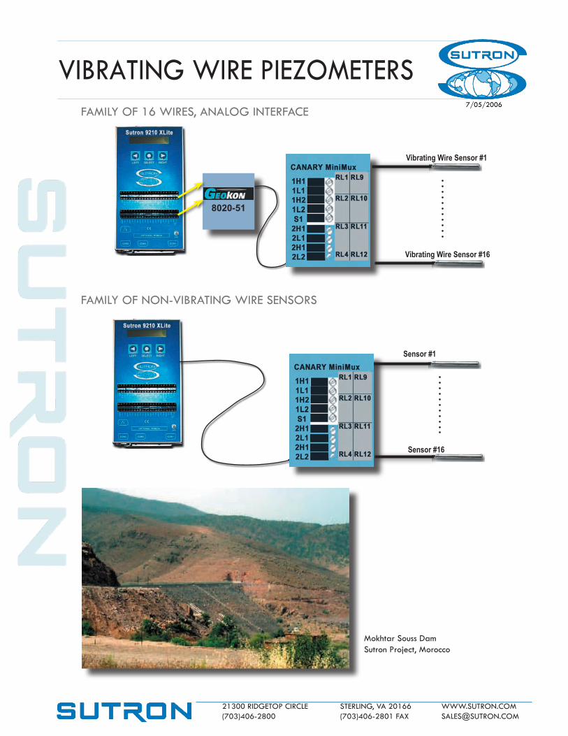
7/05/2006FAMILY OF 16 WIRES, ANALOG INTERFACE
FAMILY OF NON-VIBRATING WIRE SENSORS
8020-51
Vibrating Wire Sensor #1
Vibrating Wire Sensor #16
Sensor #1
Sensor #16
Mokhtar Souss DamSutron Project, Morocco
VIBRATING WIRE PIEZOMETERS

21300 RIDGETOP CIRCLE STERLING, VA 20166 WWW.SUTRON.COM (703)406-2800 (703)406-2801 FAX [email protected]
7/05/2006
8020-51
Vibrating Wire Sensor
Vibrating Wire Sensor
900 mHz
900 mHz
TELEPHONE CELLULARINTERNET PCMCIA CARD
Concentrator
TELEMETRY
VIBRATING WIRE PIEZOMETERSDIRECT COMMUNICATIONS FROM XPERT DATALOGGER
COMMUNICATIONS OPTIONSData can be sent from any Xpert Datalogger configuration by any of the following options that Xpert supports:
• LOS Radio
• Dialup or Cellular telephone
• Hard-wire (including serial MODBUS)
• GOES satellite
CONCENTRATORSOne of the XPert’s most powerful features is its ability to act as a cross-device repeater. This allows one XPert to act as a sensor interface for a large number of sensors and then relay the data to another XPert for telemetry. One of the many possibilities is illustrated here.