
HydroLynx Systems, Inc.hydrolynx.com/manuals/5050LL-PTK.pdf · from BFSL due to a change in...
16
HydroLynx Systems, Inc. Model 5050LL-PTK Submersible Pressure Transducer Instruction Manual Document No: A102709 Document Revision Date: December, 2004
Transcript of HydroLynx Systems, Inc.hydrolynx.com/manuals/5050LL-PTK.pdf · from BFSL due to a change in...
HydroLynx Systems, Inc.
Model 5050LL-PTKSubmersible Pressure Transducer
Instruction Manual
Document No: A102709Document Revision Date: December, 2004

HydroLynx Systems, Inc. Model 5050LL-PTK Submersible Pressure Transducer
Page 2 A102709
Receiving and UnpackingCarefully unpack all components and compare to the packing list. Notify HydroLynxSystems immediately concerning any discrepancy. Inspect equipment to detect anydamage that may have occurred during shipment. In the event of damage, any claim forloss must be filed immediately with the carrier by the consignee. If the equipment wasshipped via Parcel Post or UPS, contact HydroLynx Systems for instructions.
ReturnsIf equipment is to be returned to the factory for any reason, call HydroLynx between8:00 a.m. and 4:00 p.m. Pacific Time to request a Return Authorization Number (RA#).Include with the returned equipment a description of the problem and the name, address,and daytime phone number of the sender. Carefully pack the equipment to preventdamage during the return shipment. Call HydroLynx for packing instructions in the caseof delicate or sensitive items. If packing facilities are not available, take the equipment tothe nearest Post Office, UPS, or other freight service and obtain assistance withpackaging. Please write the RA# on the outside of the box.
WarrantyHydroLynx Systems warrants that its products are free from defects in material andworkmanship under normal use and service for a period of one year from the date ofshipment from the factory. HydroLynx Systems' obligations under this warranty are limitedto, at HydroLynx's option: (I) replacing; or (ii) repairing; any product determined to bedefective. In no case shall HydroLynx Systems' liability exceed product's original purchaseprice. This warranty does not apply to any equipment that has been repaired or altered,except by HydroLynx Systems, or that has been subjected to misuse, negligence, oraccident. It is expressly agreed that this warranty will be in lieu of all warranties of fitnessand in lieu of the warranty of merchantability.
AddressHydroLynx Systems, Inc.950 Riverside Pkwy., Suite 10West Sacramento, CA 95605Phone: (916) 374-1800Fax: (916) 374-1877E-mail: [email protected]
Copyright © 2004 by HydroLynx Systems, Inc.
Model 5050LL-PTK Submersible Pressure Transducer HydroLynx Systems, Inc.
A102709 Page 3
TABLE OF CONTENTSSECTION NO. PAGE NO.
1.0 INTRODUCTION . . . . . . . . . . . . . . . . . . . . . . . . . . . . . . . . . . . . . . . . . . . . . . . . . . 51.1 General Description . . . . . . . . . . . . . . . . . . . . . . . . . . . . . . . . . . . . . . . . . . . 51.2 Specifications . . . . . . . . . . . . . . . . . . . . . . . . . . . . . . . . . . . . . . . . . . . . . . . . 5
2.0 INSTALLATION . . . . . . . . . . . . . . . . . . . . . . . . . . . . . . . . . . . . . . . . . . . . . . . . . . . 72.1 Sensor Protection . . . . . . . . . . . . . . . . . . . . . . . . . . . . . . . . . . . . . . . . . . . . 72.2 Cable Protection . . . . . . . . . . . . . . . . . . . . . . . . . . . . . . . . . . . . . . . . . . . . . 72.3 Well Sites . . . . . . . . . . . . . . . . . . . . . . . . . . . . . . . . . . . . . . . . . . . . . . . . . . . 7
3.0 OPERATION . . . . . . . . . . . . . . . . . . . . . . . . . . . . . . . . . . . . . . . . . . . . . . . . . . . . . . 73.1 Transmitter . . . . . . . . . . . . . . . . . . . . . . . . . . . . . . . . . . . . . . . . . . . . . . . . . . 7
3.2 Calibration Check . . . . . . . . . . . . . . . . . . . . . . . . . . . . . . . . . . . . . . . 8
4.0 MAINTENANCE . . . . . . . . . . . . . . . . . . . . . . . . . . . . . . . . . . . . . . . . . . . . . . . . . . . 8
5.0 TROUBLESHOOTING . . . . . . . . . . . . . . . . . . . . . . . . . . . . . . . . . . . . . . . . . . . . . . 9
6.0 FORMS AND DRAWINGS . . . . . . . . . . . . . . . . . . . . . . . . . . . . . . . . . . . . . . . . . . . 9

HydroLynx Systems, Inc. Model 5050LL-PTK Submersible Pressure Transducer
Page 4 A102709
Model 5050LL-PTK Submersible Pressure Transducer HydroLynx Systems, Inc.
A102709 Page 5
1.0 INTRODUCTION
1.1 General Description
The Model 5050LL-PTK Pressure Transducer is a submersible transducer with a ventedcable, a moisture filter, and a termination enclosure. The stainless steel enclosedtransducer measures water level by sensing the pressure of the water above the sensorlocation.
For use as a water level sensor, the 5050LL-PTK has been designed for direct submersioninto liquids compatible with the 316 stainless steel housing and the polyurethane andTefzel jacketed cable. The sensing element is a silicon pressure cell with an integralcompliant stainless steel barrier diaphragm. A high pressure design allows the sensor tobe subjected to pressures well beyond the specified operating range without any damageto the sensor.
An outside diameter of 1 inch allows use of the 5050LL-PTK in places where sensors withlarger diameters cannot fit. The sensor still has sufficient mass to sink to the requireddepths. The output of the 5050LL-PTK is compatible with HydroLynx data transmitters anddata loggers.
Cable lengths are specified based upon the length of vented cable required to fullysubmerge the sensor with enough extra length to place the end of the vented cable aboveflood level. Additional signal cable may be used to reach from the termination enclosureto the data transmitter location. This added cable is standard, unvented, three conductorcable. The termination enclosure is located as close as possible to the sensor while at thesame time remaining above the flood water level. The data transmitter end of the signalcable is equipped with a circular, MS style, four-pin connector.
1.2 Specifications
ELECTRICALPower required: 10 to 40 Vdc, 12 Vdc typicalCurrent drain: 20mAdc maximumPower supply rejection:
Vdc output: <±0.001%FSO/VdcmA output: <±0.05% FSO/Vdc
Output signal:0-5 Vdc: 3-wire standard4-20 mAdc: 2-wire optional
Zero offset:0-5 Vdc: ± 50 mVdc max4-20 mVdc: ± 0.06 mAdc max
Output impedance: <10 ohmsInsulation resistance: >100 megohms at 50 VdcCircuit protection: Polarity, Surge, Shorted Output

HydroLynx Systems, Inc. Model 5050LL-PTK Submersible Pressure Transducer
Page 6 A102709
PERFORMANCEPressure range: 0-5 through 0-250 PSIGStatic accuracy: ±0.25% FSO typical,
0.50% FSO maximum (includes combined errorsdue to nonlinearity, hysteresis, and nonrepeatabilityfor a BFSL at 25°C per ISA S51.1)
Thermal error: ±0.05% FSO/°C (maximum allowable deviationfrom BFSL due to a change in temperature per ISAS51.1)
Burst pressure: X 2.0 rated pressureProof pressure: X 1.5 rated pressureResolution: Infinite, depends upon monitoring deviceFrequency response: 1 k Hz
ENVIRONMENTALOperating temperature range: -20 to +70°CCompensated temperature range: 0 to 50°CBarometric compensation: Vented to atmosphereVibration response
10g's to 2000 Hz: NilShock: 1000 g's for 1 ms in each of the 3 orthogonal axes
does not affect calibration
PHYSICALSize: 3.53" long by 1" diameterWeight: 7 oz without cableWetted materials: 316, Stainless Steel, VitonMounting: Suspended by vented cable. For turbulent
conditions, specify optional mounting bracket
CABLECable type: Polyurethane jacket, shielded, with polyethylene
vent tube and Kevlar tension members, 200 lbs pullstrength Tefzel jacket optional
Cable weight: 0.05 lbs per footMin o.d.: 0.28"Max o.d.: 0.31"Number of conductors: 3 or 4Insulation: PVCShield: 36 gauge spiral tinned copperWire size: 22 AWG (19/34) tinned copperResistance: 16.45 ohms per 1000 feetVent tube: 0.060" o.d. polyethylene

Model 5050LL-PTK Submersible Pressure Transducer HydroLynx Systems, Inc.
A102709 Page 7
2.0 INSTALLATION
2.1 Sensor Protection
The pressure transducer installation should provide protection against possible damagefrom debris during high and low water flows. Protection must also be provided to preventexcessive silting onto the sensor. Two mounting accessories are available for the sensor:
5050LL-PT-BM Mounting bracket for bolting the sensor onto a concrete abutment
5050LL-PT-CAB Concrete anchor for mounting the sensor in a stream
2.2 Cable Protection
Although the vented cable attached to transducer is waterproof, additional cable protectioncan be achieved using plastic or metal pipe. The pipe should cover the cable from thesensor location to the termination enclosure. Metal conduit or pipe is recommended as thebest method of cable protection.
For installations involving hanging the sensor down a well or conduit, use strain reliefsdesigned for cables. These strain reliefs are constructed of steel mesh and are readilyavailable. Also if space allows, provide a loop of cable just above the strain relief to allowextra protection against pulling from below. For extremely long cables, strain reliefs shouldplaced at several places along the cable.
2.3 Well Sites
The 5050LL-PTK may be used to measure well water depth. The sensor is usually placeddirectly into the well. The cable is able to withstand up to 200 pounds of tension and willnot stretch. The cable can be tied off to hold the sensor at the required depth.
3.0 OPERATION
3.1 Transmitter
The 5050LL-PTK Pressure Transducer connects to the HydroLynx Model 5096 DataTransmitter via a four-pin circular connector. A 15-foot length of cable with the connectorattached is supplied with the termination enclosure. The connector is normally plugged intothe data transmitter's 4-pin analog port. The connector may also be connected into the4-pin barometric pressure sensor port by rotating the index slot of the connector.
The data transmitter powers the pressure sensor through the switched +12 volts powerline. The sensed pressure is converted by the sensor's internal signal conditioning into a0-5Vdc or a 4-20 mAdc signal. The data transmitter converts the signal into a 0 to 255decimal value. The sensor value is received by the base station and is converted intowater level information.
HydroLynx Systems, Inc. Model 5050LL-PTK Submersible Pressure Transducer
Page 8 A102709
To properly set the base level of the pressure transducer, refer to the operating manualfor the base station and use the calibration data sheet supplied with the transducer.
3.2 Calibration Check
The 5050LL-PTK is calibrated at the factory and is furnished with a calibration data sheet.Calibration of the sensor can be checked using a known column of water and a +12 Vdcpower source.
Placing the sensor into a known depth of water should produce an output signalproportional to the depth of the water. Refer to the calibration data sheet to obtain thecalibrated range of the sensor. Make certain that the sensor is powered by a stable powersource during the test.
Place the transducer into the column of water and measure the sensor's output signal.Using the calibrated range of the sensor, calculate the height of the water based upon themeasured voltage:
RANGE ÷ 5 VDC = Ft/Volts
MEASURED VOLTAGE X Ft/Volts = Height Of Water
When used with the 5096 Data Transmitter, adjustments can be made in the programmingset-up to compensate for slight changes in the sensor's calibration. The 5050LL-PTKsensor has no user accessible adjustments. Significant changes in the sensor calibrationrequires that the sensor be returned for factory testing and adjustment or replacement.
4.0 MAINTENANCE
The Model 5050LL-PTK Pressure Transducer should require minimal maintenance. Duringeach site maintenance visit, it is advisable to check the operation of the pressuretransducer. If a manual depth gauge is located nearby, a comparison can be made of thelatest sensor reading with that of the depth gauge. Visually check that the cables are ingood condition. Check that the transducer has not moved and is still securely in place. Ifpossible, clear away any silt or debris from the transducer.
Water collecting in the vent tube is a major cause of pressure transducer problems.Excessive moisture in the vent tube may driven off by heating the sensor and its cable.Place the transducer and its coiled cable into a pan and heat the pan in an oven at 122°F(50°C) for two hours. The oven temperature must not exceed 122°F. An alternate methodinvolves hanging the transducer in a vertical position with the sensor at the top for eightto ten hours. The water should drain down and out of the vent tube.
Algae or marine growth is also a major problem for pressure transducers located in warmwater. There is no perfect solution to this problem. One method of protection involveswrapping the sensor with copper wire such as that found in scouring pads. Any marine

Model 5050LL-PTK Submersible Pressure Transducer HydroLynx Systems, Inc.
A102709 Page 9
growth will be deposited onto the copper and as it erodes the copper will drop off. Thecopper wire may also be removed manually during scheduled maintenance. Anotheralternative is to impregnate the stainless steel housing with an antifouling chemical.
5.0 TROUBLESHOOTING
If data from the pressure transducer seems high, check for excessive silting around theopen end of the sensor. If other errors appear, check that the transducer is mountedsecurely and that its position has not changed. If the cause of the erroneous data is notdue to changes in the physical surroundings, the next step is to determine whether thetransducer is faulty or the data transmitter is at fault.
Refer to the data transmitter manual for testing the transmitter for errors. If the output vsthe water pressure as compared on the calibration curve is correct, the problem is in thetransmitter.
To determine if the transducer is at fault, connect the sensor to a stable 12 Vdc source.Disconnect the signal connector from the transmitter and measure the sensor outputvoltage at the terminal block inside the cable termination enclosure. Determine the presentstream or reservoir water level and calculate the sensor output voltage. The measuredvoltage should agree or be very close to the calculated value.
Another method for testing the pressure transducer operation is to blow into the open endof the vent filter. Blowing into the tube increases the pressure on the back side of thesensor and in turn creates a change in the output. Typically, an average person can exertabout 1 psi by blowing into the tube.
Inspect the cable installation for problems. Severe crimps, tight bends, or loops with aradius of less than 1 inch will cause the sensor to read incorrectly. Wherever the ventedcable passes into an enclosure, check to see that the cable grip does not pinch the cable.The maximum allowable force on the vented cable is 15 ft/lbs.
6.0 FORMS AND DRAWINGS
AC107408 Outline - SensorAC107407 Wiring Diagram - Terminal EnclosureAC107867 Wiring Diagram - Sensors to 5096NAC107587 Wiring Diagram - PCB, 4-20 mA Output Terminal EnclosureAC100901 Curve - Voltage vs Feet of WaterA100966 5050LL-PTK Test ResultsA104973 Maintenance Report


HydroLynx Systems, Inc. ! 950 Riverside Pkwy., Suite 10 ! West Sacramento, CA 95605Phone 916-374-1800 ! Fax 916-374-1877 ! Email [email protected]
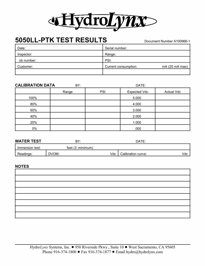
5050LL-PTK TEST RESULTS Document Number A100966-1
Date: Serial number:
Inspector: Range:
ob number: PSI:
Customer: Current consumption: mA (20 mA max)
CALIBRATION DATA BY: DATE:
Range PSI Expected Vdc Actual Vdc
100% 5.000
80% 4.000
60% 3.000
40% 2.000
20% 1.000
0% .000
WATER TEST BY: DATE:
Immersion test: feet (3' minimum)
Readings: DVOM: Vdc Calibration curve: Vdc
NOTES

HydroLynx Systems, Inc. ! 950 Riverside Pkwy., Suite 10 ! West Sacramento, CA 95605Phone 916-374-1800 ! Fax 916-374-1877 ! Email [email protected]
Maintenance Report Document No. A104973
SITE INFORMATION
Location: Gauge type: ID#:
Purpose/Comments:
Weather conditions:
EQUIPMENT INFORMATION
Equipment Model # Asset # Comments
Data transmitter
Antenna
Battery
Solar panel
Sensors
TEST DATA
POWER
Battery voltage w/o load: Vdc w/ load: Vdc Difference: Vdc
Current Standby: :A w/ load: A
Solar panel w/o load: Vdc w/ load: A Reverse: mA
SIGNAL OUT - TX
Power out: W Reverse power: W Freq error: Hz Dev: ± kHz
SIGNAL IN - SENSOR
Sensor Measured Reading Comments
COMMENTS


