OPen-file Report 569: A hydrogeologic investigation of groundwater ...

Hydrogeologic Investigation Guide
Delaware Department of Natural Resources and
Environmental Control
Tank Management Section
June 2012

2
Delaware Department of Natural Resources and Environmental Control
Division of Waste and Hazardous Substances
Tank Management Section
Mailing Address: DNREC-TMS
391 Lukens Drive
New Castle, DE 19720
Telephone: 302-395-2500
Fax: 302-395-2555
Website: www.dnrec.delaware.gov/Tanks/
To report a release call: 1-800-662-8802

Table of Contents
Hydrogeologic Investigation Checklist .................................................................. 1
List of Acronyms ...................................................................................................... 2
Hydrogeologic Investigation Guide ........................................................................ 3 Part I – Introduction .................................................................................................................................. 3
1.0 Introduction ............................................................................................................................... 3 2.0 Responsibility ........................................................................................................................... 3 3.0 Work Plans ................................................................................................................................ 4 4.0 How to use the Hydrogeologic Investigation Guide ................................................................. 4 5.0 Summary of Intent .................................................................................................................... 5 6.0 Professional Geologist (PG), Professional Engineer (PG) Signature Requirements ................ 5 7.0 Aboveground Storage Tanks (ASTs) ........................................................................................ 6
Part II – Data Collection and Reporting ................................................................................................... 7 1.0 Release Information .................................................................................................................. 7 2.0 Quality Assurance and Quality Control .................................................................................... 8 3.0 Defining the Vertical and Horizontal Extent of Soil Contamination ........................................ 8 4.0 Groundwater Flow Direction .................................................................................................. 10 5.0 Defining the Vertical and Horizontal Extent of Groundwater Contamination ....................... 12 6.0 Points of Exposure (POEs) ..................................................................................................... 13
Part III – Data Interpretation .................................................................................................................. 15 1.0 Contaminant Migration Pathways (CMPs) ............................................................................. 15 2.0 Risk Assessments .................................................................................................................... 15 3.0 Human Risk Assessment and Management ............................................................................ 16 4.0 Environmental Risk Assessment and Management ................................................................ 17 5.0 Conceptual Site Model (CSM) ................................................................................................ 17 6.0 Recommendation .................................................................................................................... 18
List of Attachments to be included with Hydrogeologic Investigation Report 20
Appendices ..............................................................................................................21 Corrective Action Process Flow Chart ................................................................................................... 22 QA/QC Guide ......................................................................................................................................... 23 Example Boring/Well Log ...................................................................................................................... 25 Soil Classification Guide ........................................................................................................................ 26 Example Data Tables .............................................................................................................................. 29 List of CSM Websites ............................................................................................................................. 30 Referenced ASTM Standards ................................................................................................................. 31

4

1
Hydrogeologic Investigation Checklist Check below if included:
____ Project information
Facility ID#: _________________________________ File Code: 34
Facility Project #: _________________________________
Facility Name: _________________________________
Facility Address: _________________________________
Tax Parcel ID: _________________________________
____ Responsible Party information
Responsible Party: ________________________________
Address: ________________________________
Contact: ________________________________
Data Collection and Reporting Page in Guide
____ Release Information (cause, amount, etc.) ………………………………………………. 7
____ QA/QC procedures ……….. ………………….………………………………………….. 8
____ Investigative work conducted ………………… ………………………………………….. 8
____ Vertical and Horizontal extent of Soil contamination ….……………………………….. 9
____ Groundwater Flow Direction …………………..………………………..……………...... 10
____ Vertical and Horizontal extent of Groundwater contamination ………………………. 11
____ Points of Exposure ………………… ……………………………………………….…… 13
Data Interpretation
____ Risk and Risk-Based Screening Levels ……………………………………………………. 15
____ Conceptual Site Model ……………………………………………………………….…… 17
____ Recommendations ……………………………………………………………………….. 18
Which best fits your recommendations (check all that apply):
____ No Further Action
____ One year of monitoring
____ Remedial Action
____ Further investigation
____ Tier 2 evaluation
____ Other
Appendices
____ Laboratory reports with chain of custody documentation
____ Regional figure
____ Facility scale figure
____ Groundwater flow figure
____ Contaminant distribution figures
____ soil
____ groundwater
____ Boring logs/well logs
____ Well Permits
____ Point of exposure figure
____ Cross sections
____ Analytical results tables
____ Groundwater gauging table
____ Financial Responsibility Survey (if received)

2
List of Acronyms
AST Aboveground Storage Tank
ASTM American Society for Testing and Materials
CMP Contaminant Migration Pathway
COC Chemical of Concern
CSM Conceptual Site Model
DERBCAP Delaware Risk Based Corrective Action Program
DNREC Department of Natural Resources and Environmental Control
HI Hydrogeologic Investigation
HIR Hydrogeologic Investigation Report
ID Identification
LIF Laser Induced Fluorescence
LCSM LNAPL Conceptual Site Model
LUST Leaking Underground Storage Tank
MIP Membrane Interface Probe
MTBE Methyl Tertiary Butyl Ether
NFA No Further Action
PE Professional Engineer
PG Professional Geologist
POC Point of Compliance
POE Point of Exposure
QA Quality Assurance
QC Quality Control
RAWP Remedial Action Work Plan
RBCA Risk Based Corrective Action
RBSL Risk Based Screening Level
RP Responsible Party
TMS Tank Management Section
UST Underground Storage Tank

3
Hydrogeologic Investigation Guide
Part I – Introduction
1.0 Introduction
1.1 The Hydrogeologic Investigation Guide (referenced as “this guide”) is one document in a
series of guidance documents that the Department of Natural Resources and Environmental
Control, Tank Management Section (DNREC-TMS) has created (or will create) to assist
consultants, responsible parties, and the public with following the requirements of Part E of
DE Admin. Code 1351, State of Delaware Regulations Governing Underground Storage
Tank Systems (the UST Regulations).
1.2 This guide will focus on how to successfully complete the Hydrogeologic Investigation (HI)
requirements as required in Part E §4.2 of the UST Regulations.
1.3 This guide is to be used in conjunction with the Delaware Risk-Based Corrective Action
Program (DERBCAP).
1.4 The HI is perhaps the most important part of the corrective action process (Corrective Action
Process Flow Chart in appendix) because it defines the extent of the confirmed release.
1.5 The intention for this guide is to elicit complete HIs to allow for better protection of human
health, safety, and the environment. In addition, Leaking Underground Storage Tank (LUST)
projects will progress more quickly towards a no further action (NFA) determination by the
DNREC-TMS.
1.6 Since all projects are driven by risk, the completion of every task covered in this document is
not necessary for all situations.
2.0 Responsibility
2.1 It is the responsibility of the Responsible Party (RP) to successfully complete the HI
requirements as stated in the UST Regulations, the Hydrogeologic Investigation Required
letter, and all subsequent correspondence concerning a confirmed release.
2.2 Part E § 4.2.2 of the UST Regulations requires the RP to submit the complete Hydrogeologic
Investigation Report (HIR) to the DNREC-TMS within 120 days following receipt of the
Hydrogeologic Investigation Required letter. Incomplete HIRs will not be accepted and will
not be considered for meeting the 120 day deadline.
2.3 Two copies of the HIR should be submitted to the DNREC-TMS project officer for review.
One of the copies should be an electronic copy.
2.4 In general, the RP hires a qualified environmental professional, or consultant, to assist them
in meeting the investigation and reporting requirements of the HI and HIR.
2.5 It is important to realize that although the RP hires a consultant, it is ultimately the
responsibility of the RP (not the consultant) to meet the requirements and deadlines set in
the UST Regulations and by the DNREC-TMS; therefore, it is important for the RP to
make sure the consultant is meeting deadlines on their behalf.
2.6 Unless the RP is well-versed in conducting a HI, it is recommended that the RP requests
proposals from multiple consultants. To address the same LUST project, different consultants
will have different approaches that come with varying time frames and costs.
2.7 The RP should hire a consultant based on, but not limited to, weighing the following factors:
Experience
Professionalism
PG and/or PE licenses as necessary
References
Cost
Approach
Reliability

4
2.8 The hydrologists at the DNREC-TMS are always available to discuss different approaches
and technologies.
2.9 During the process of the HI, the reporting requirements of Part E § 1 of the UST Regulations
must be followed. The DNREC-TMS must be notified immediately if any of the following
observations are made:
Any private or public well impact
The appearance of mobile or free light non-aqueous phase liquid (LNAPL)
Any surface water impact resulting in a sheen
Anytime there is an immediate threat to human health and safety or the environment.
3.0 Work Plans
3.1 The DNREC-TMS recently reviewed its corrective action process to more efficiently move
projects toward NFA determinations and to lessen the burden of administrative work (report
and work plan reviewing, letter writing, etc.).
3.2 The first step in streamlining the DNREC-TMS’s corrective action process was the
elimination of the requirement to submit a HI work plan for the initial investigations. Work
required after the submittal of the initial HIR will still require a work plan.
3.3 In the past, the scopes of approved work plans were sometimes insufficient in delineating the
full extent of the contamination. In these cases decisions to expand the investigations could
have been made in the field to more quickly delineate the plume and provide useful
information for the project. However, these “expanded” investigations were not performed
because they were not pre-approved by the DNREC-TMS. As a result, several weeks were
added to the project life and additional costs were incurred by the RP through the
development of additional work plans, field mobilizations, etc.
3.4 The DNREC-TMS expects that by eliminating the work plan step in the corrective action
process, a more flexible, field-driven investigation will be performed. Decisions made in real
time will allow for an additional field mobilization, if necessary, within the 120 day deadline.
Better field time management will permit time for more complete data collection, allowing
for more constructive recommendations for a path forward or a warranted request for a NFA
determination.
3.5 While a work plan will no longer be required for a HI, the DNREC-TMS welcomes and
encourages meetings or teleconferences to discuss your planned investigation in advance
of any field mobilizations.
4.0 How to use the Hydrogeologic Investigation Guide
4.1 The purpose of the HI checklist is to act as a quick visual guide to ensure that the HI is
complete and contains the appropriate sections and report appendices.
4.2 The HI checklist must be filled out and included as the cover of the HIR. It is acceptable to
place the HI checklist behind your hired consultant’s coversheet.
4.3 This guidance document is intended to help the RP and their hired consultant understand
what the DNREC-TMS expects in terms of a complete HI for a range of projects.
4.4 Although this guide covers a topic of a technical nature, it is written in such a way that a non-
technical reader can form a general understanding of the concepts and use the information to
review a consultant’s report and recommendations. However, the majority of the material in
this guidance document assumes the reader has a basic technical background and is geared
toward the professionals that will be conducting the HI.
4.5 The content of this guide is intended to ensure that good quality data is collected and allow
for good professional decision making and accommodate a wide variety of LUST projects
and situations to be addressed.
4.6 The sections of this guidance document beginning in Part II are organized as follows:

5
4.6.1 The section title will begin a new section (e.g., 1.0) and will be printed in bold.
The section title will correspond to the table of contents and loosely to the HI
checklist.
4.6.2 The first subsection (e.g., 1.1) will have the title of Topics of discussion, and
will be a bulleted list of topics which will make up the body of the report for
that section.
4.6.3 The second subsection (e.g., 1.2) will have the title of Report Appendices to be
included, and will be a bulleted list of appendices (i.e., figures, tables, lab
reports, etc.) that should accompany the HIR. The appendices will be relevant
to the section. If during the investigation it is found that appendices listed are
not applicable to the project, they do not need to be submitted.
4.6.4 The third subsection (e.g., 1.3) will be the guidance on how to create and
submit required Report Appendices and how to sufficiently investigate and
report on topics which are integral to the report.
4.7 Some requirements are repeated in several sections. Double submittal is not expected and
combining requirements is recommended. For example, in Part II Sections 3.0 and 4.0,
figures are required to be submitted detailing the locations of borings and sample points. If
the data required in said parts can be clearly depicted with one figure, one figure is all that is
needed.
4.8 Due to the risk-based nature of the DNREC-TMS Program, written justification explaining
why completing a requirement as prescribed in this guide is not applicable due to the risk
posed by a facility is as sufficient as completing the requirement as outlined in this guide
when the risk warrants its completion. For example, door-to-door well surveys may not be
necessary if the exposure pathway can be eliminated.
5.0 Summary of Intent
5.1 The DNREC-TMS recognizes that each LUST project presents its own unknowns and
complications and that some methods for completing a HI are more beneficial than others for
different sites and at different times (e.g. temporary direct push sampling versus permanent
monitoring wells and vice versa).
5.2 The DNREC-TMS would like to see all projects move as efficiently towards a NFA
determination as possible while providing for the protection of human health and safety, and
the environment. The DNREC-TMS understands that achieving every task in this document
is not necessary for completing that goal and does not expect extra, non-value-added work to
be conducted.
5.3 The DNREC-TMS is always available for guidance.
6.0 Professional Geologist (PG), Professional Engineer (PG) Signature Requirements
6.1 According to Part E §4.2.3 of the UST Regulations, a HIR is required to be signed by a
Delaware-licensed PG or PE. This requirement is in place to ensure the quality of the
investigation and accuracy of data interpretation because it has a direct impact on the well-
being of the environment and individuals.
6.2 In some cases, when a release is limited and an investigation can be completed through Tier 0
soil sampling only, PG or PE signature may not be necessary. However, prior DNREC-TMS
approval will be required.
Here is an example of 6.2:
A 550-gallon heating oil UST is removed with composite and grab soil samples collected and
groundwater is not encountered. The samples are analyzed for DRO with the results of the grab
sample being reported at 1,800 mg/Kg, which is over the action level of 1,000 mg/Kg. A HI is then
required. The RP hires a consultant who plans to collect a soil sample from a deeper depth and
from four locations around the former UST with all samples being analyzed for DRO. The results
of this investigation do not need to be signed by a PG or PE.

6
7.0 Aboveground Storage Tanks (ASTs)
7.1 While this guide was created to aid in completing a HI for a LUST facility, the general
principals are applicable for AST facilities with a confirmed release and this guidance should
be followed to complete the investigation required in Part E, § 1.0 in the DE Admin. Code
1352, State of Delaware Regulations Governing Aboveground Storage Tanks (the AST
Regulations).
7.2 When following this guide to complete an investigation at an AST facility with a confirmed
release, it is important to remember that the AST Regulations use different terminology and
definitions and that the AST Regulations must be followed.
7.3 Just as in LUST projects, the DNREC-TMS project officer is available for teleconferences or
meetings.
7.4 For additional guidance, please review the Aboveground Storage Tank Site Assessment
Guidance document found at: http://www.dnrec.delaware.gov/tanks/Pages/Corrective-
Action-Program.aspx
7
Part II – Data Collection and Reporting
1.0 Release Information
1.1 Topics of discussion:
Identify how the leak was caused, when the leak began, and how the leak was identified.
Report the estimated volume of the release and what was released.
Report any actions conducted as an emergency effort by any party to minimize the
release (e.g. trenching, pumping).
1.2 Report Appendices to be included:
Documentation supporting release volume calculation, including inventory records
Repair documentation
Photos
Field Orders and/or Secretary Orders from DNREC emergency personnel
General Site Figure
Regional Figure
Other applicable documentation
1.3 Guidance
1.3.1 The cause of a release is sometimes very difficult to pinpoint, but professional
judgment based on how the release was identified can provide assistance. A
release is commonly identified during UST removal activities, retrofit
activities, or during a Phase II assessment. The location of contamination will
aid in producing an approximate cause of the release. In addition, this data is
now required to be collected under the Energy Policy Act of 2005 (Pub.L. 109-
58) and is important in the development of a conceptual site model (CSM)
(Part III Section 5 of this guide).
1.3.2 Carefully review all data available for the specific site. Review UST removal
or closure-in-place reports, data on previous LUST projects at the facility, and
basic information on nearby LUST facilities (especially if a second source is a
potential).
1.3.3 Speak to the DNREC-TMS compliance officer, if one is assigned. The project
officer can and will provide you with this information.
1.3.4 Other than in emergency situations, determining the exact time that a leak
began may be impossible. Estimates of when the release began may be aided
by reviewing inventory records and product delivery receipts and looking for
continuous net losses or receiving excessive deliveries. This documentation
may be obtained from the UST operator, DNREC-TMS files, or the UST
owner.
1.3.5 Inventory records and product delivery receipts can also aid in approximating
the volume of product released. In addition, by defining the extent of soil
contamination, a loose estimate of volume released can be obtained.
1.3.6 If remedial actions were taken before receipt of the letter informing the RP that
a HI is required, details of those actions and backup documentation must be
gathered and submitted.
1.3.7 A general figure of the facility must be prepared and submitted with the HIR.
The figure must be set to an appropriate scale, have a north arrow and legend,
and include the locations of present and former USTs, present and former
dispensers, present and former piping runs and utilities, and all structures.
1.3.8 A figure of the region must be prepared and submitted with the HIR. The figure
must be scaled appropriately to allow someone who is not familiar with the
area to find the facility.

8
2.0 Quality Assurance and Quality Control
2.1 Topics of discussion
Briefly discuss the QA/QC that was performed during this HI
Discuss any potential problems that have been identified through your QA/QC efforts.
2.2 Report Appendices to be included:
QA/QC Plan
Chain of Custody forms with appropriate information
Field logs
Calibration logs
Analytical summary reports
2.3 Guidance
2.3.1 QA/QC is crucial for ensuring that the data reported and decisions made from
that data are sound. Part E § 4.3 of the UST Regulations requires the
development, implementation, and submittal of a QA/QC plan.
2.3.2 Analytical reports must always include a chain of custody.
2.3.3 When relinquishing the chain of custody, signatures, times, and dates must be
documented. In addition, the temperature of the samples when received by the
lab must be noted on the chain of custody or documented in a laboratory
summary report. If your lab does not currently provide this service, it should be
requested.
2.3.4 All groundwater and soil sampling events from which volatile compounds are
being analyzed for must include one trip blank per cooler.
2.3.5 One equipment blank sample must be collected per day when non-dedicated
equipment is used.
2.3.6 All samples must be collected and placed in the appropriate, sterile containers.
2.3.7 All effort must be made to deliver samples to the laboratory within 24 hours of
the sampling event. If this is not possible, a description of the handling of the
samples must be included in the QA/QC section of the HIR.
2.3.8 Samples must be kept at ≤ 6 °C until delivered to the laboratory.
2.3.9 Contaminant and analytical method specific holding times must be met.
2.3.10 If sample results are reported with expired holding times or excessive
temperatures, the DNREC-TMS may not accept the results and may require the
samples be recollected.
2.3.11 Field blanks, duplicate samples, and split sampling may be necessary.
2.3.12 Having the lab run matrix spikes and matrix spike duplicates is recommended.
2.3.13 Lab reports must include the results of matrix spikes, matrix spike duplicates,
and instrument calibration results.
2.3.14 All sampling equipment that is not dedicated or disposable must go through
proper decontamination procedures to protect against cross contamination.
ASTM practice D5088 provides procedures for decontamination.
2.3.15 Instruments used for collecting field measurements should be properly
calibrated according to the manufacturer’s standards. Calibration dates and
times must be recorded in field books, field logs, or equipment logs.
2.3.16 Further guidance and explanation is available in the appendix.
3.0 Defining the Vertical and Horizontal Extent of Soil Contamination
3.1 Topics of discussion:
Interpret analytical and screening data collected to date to determine the volume of soil
contamination.
Discuss sampling methods.
Discuss screening methods.
Discuss how source mass is contributing to daughter plumes.
Report any identified data gaps and propose how they will be filled.

9
3.2 Report Appendices to be included:
Figure with soil sample and boring locations
Figure with interpreted extent and concentrations of soil contamination
Lab analytical reports
Table of soil sample analytical results
Boring log(s)
Cross section(s)
3.3 Guidance
3.3.1 Part E §4.2.1.2 and §4.2.1.3 of the UST Regulations require that the horizontal
and vertical extent and distribution of the Release be determined. This
requirement includes soil contamination. Defining the extent of soil
contamination is a critical part of a HI. Note that the data gathered may come
from many phases of work at a tank site, from tank removal or closure-in-place
through HI and remediation.
3.3.2 Soil samples must be collected in the proper laboratory-provided bottleware,
according to the method of analysis.
3.3.3 Defining the extent of soil contamination is integral to the following:
Estimating the amount of source mass contributing to dissolved and vapor
contamination;
Aiding in selection of locations for groundwater sampling or monitor well
installation;
Aiding in remedial design or modeling;
Estimating the potential extent of soil overexcavation, either during
underground storage tank removal or as a remedial strategy;
Determining risks, such as potential for exposure to contaminated soil during
excavation. This includes long term stewardship of a property, when residual
contamination is left in soil, following a risk-based NFA determination.
3.3.4 Collection of data can occur in every phase of corrective action, but early
determination of the extent of soil contamination will serve to guide further
corrective actions. Techniques such as membrane interface probe (MIP) or
laser-induced fluorescence (LIF) are quick ways to develop a 3-dimensional
picture of contamination at the site. These investigative tools may cost more
initially but can lower costs through the collection of fewer soil samples, less
staff time associated with field mobilizations and sample collection, and
providing the ability to target well placement.
3.3.5 Ensure that soil data collection is integrated with groundwater data.
3.3.6 All opportunities for collecting soil data, such as during monitor well
installation, excavation, installation of remediation systems, etc., should be
exploited.
3.3.7 It is beneficial to review soil analytical data from tank system removal, closure-
in-place, and retrofit reports to aid in defining extent of soil contamination.
You may need to check the DNREC-TMS facility file for the information.
3.3.8 Field screening information is a part of delineating soil contamination. Ensure
that QC is employed in screening data collection, data is recorded accurately,
and equipment is properly calibrated.
3.3.9 Field screening techniques must be used in selecting representative soil
samples for laboratory analyses. Samples collected, bagged and used for
headspace readings must not be submitted to the lab for analysis.
Grab soil samples must be collected from the points of highest screening
readings or areas of staining and at the interval directly above the water table.
If screening readings are non-detect, a grab sample can be collected from the
interval above the water table.

10
If detections are detectable but uniform, a grab sample from above the water
table and a composite sample of the boring must be collected.
3.3.10 Soil borings must continue until evidence of contamination is screened out.
Soil borings that stop at the water table and still exhibit signs of contamination
do not vertically delineate contamination
3.3.11 Soil samples must be collected below the water table from a representative
number of locations if staining is observed. However, borings may be
terminated if a confining layer of two feet or greater is encountered below the
surface aquifer.
3.3.12 You must clearly describe in the HIR how the extent of contamination was
determined. That is, describe what laboratory and/or field screening data was
used in determining the lateral and vertical extent of soil contamination.
3.3.13 A figure must be included displaying the horizontal extent of soil
contamination and defining areas of varying concentrations. The figure must be
to scale with a north arrow and legend. All soil borings and sample locations
related to the current release should be included on the figure.
3.3.14 A table must be prepared summarizing analytical results. The table must
include local identification (SB-1), DNREC well permit number, proposed
RBSLs, and laboratory detection limit if result is not detected. An example is
included in the appendix.
3.3.15 A cross-section displaying the extent of soil contamination (soil sample
locations, screening results, observed staining, lithology, etc.) as well as
groundwater sampling data (lithology, sample locations, well screens,
screening results, water elevations, etc.) must be prepared to support the
discussion on the vertical extent of soil contamination.
3.3.16 Boring/well logs must include field screening information, including notation
of intervals from which screening information and soil samples were collected.
Boring logs must also include drilling method, local identification (SB-1) and
the DNREC well permit number (if applicable). In addition, lithology must be
described by using common nomenclature such as the Unified Soil
Classification System (ASTM D2488). An example is included in the
appendix.
3.3.17 For releases near subsurface structures, consider where released product may
have migrated, such as into drains, trenches, along walls, pipes, etc. Soil
contamination may “hide” in such areas.
4.0 Groundwater Flow Direction
4.1 Topics of discussion:
Discuss how the groundwater flow direction was determined.
Interpret data collected to date to determine the migration of a groundwater
contamination plume.
Starting with the larger conduits or preferential pathways consider the potential for them
to influence groundwater flow and the overall CSM (Part III Section 5.0).
Discuss the ultimate discharge location of groundwater
Report any identified data gaps and propose how they will be filled.
4.2 Report Appendices to be included:
Figure with sample and groundwater gauging locations
Figure(s) with inferred groundwater elevation and flow direction
A figure with preferential pathways identified
Well Permits
A table with gauging or groundwater elevation data
4.3 Guidance

11
4.3.1 If groundwater contamination is confirmed, the RP will need to determine in
what direction groundwater flows to determine if any POEs are at risk.
4.3.2 In early stages of an investigation, or perhaps as the only means in a limited
investigation, topographic maps, information on nearby sites, published works,
or information on drainage basins can be used.
4.3.3 The best way to determine groundwater flow direction is through an installed
monitoring well network. For the outcome of the gauging data to be acceptable
the following principles must be followed:
A minimum of three wells must be used and the wells must be installed in a
configuration that allows for determining groundwater flow, like an
equilateral triangle. In other words, the wells must be well distributed over
the area of interest. Wells installed in a straight line or near straight line will
not provide useful data in determining groundwater flow.
Wells used in determining groundwater flow must be screened at
approximately the same interval. Deep well data should not be used for
determining shallow groundwater flow or vice versa.
Wells to be used for determining groundwater flow should not be installed in
former tank pits or other areas of non-native fill. Groundwater elevations
tend to be distorted in these areas and will affect results. However, wells
installed in these areas can provide useful contamination data.
Wells used to assess the surficial aquifer must be screened several feet above
the groundwater table to allow for fluctuation in the water level and to allow
LNAPL to flow into the well.
Groundwater monitoring wells must be adequately developed to provide
good communication with the aquifer. ASTM guide D5521 provides a
framework for well development.
While a professional survey of wells is not required, a survey must be
conducted by skilled individuals to obtain top of casing elevations.
Well elevations must be in reference to an immobile and permanent
benchmark. This benchmark should be noted in the discussion of how
groundwater flow direction was determined to allow for the replication of the
survey data if necessary.
Groundwater elevations can be collected from temporary wells or from
screen points. However, that data should not be used as the only means of
determining groundwater flow direction due to the variability associated with
those installation methods.
4.3.4 When groundwater elevations are collected, a scaled figure must be prepared
with groundwater elevations, contours and groundwater flow direction
indicated.
4.3.5 Groundwater gauging data must be tabulated. The table must include the well
ID, depth to water, top of screened interval height, groundwater elevation,
depth to product, and product thickness. An example can be found in the
appendix of this guide.
4.3.6 Preferential pathways in the form of man-made conduits (former UST system
trenches, sewer lines, electric lines, etc.) affect the flow of groundwater and
vapors and the overall distribution of contamination. Possible effects of man-
made conduits must be considered.
4.3.7 RBSLs established in the DERBCAP Guide were created using generic
parameters (hydraulic conductivity, seepage velocity, gradient). You are
required to establish estimates of hydraulic conductivity and gradient based on
the information available.

12
5.0 Defining the Vertical and Horizontal Extent of Groundwater Contamination
5.1 Topics of discussion:
Interpret data collected to date to determine the vertical and horizontal extent of
groundwater contamination.
Discuss any impacted or potentially impacted off site properties.
Discuss the potential for plume diving to occur.
Report any identified data gaps and propose how they will be filled.
5.2 Report Appendices to be included:
Figure with sample locations
Figure(s) with interpreted extent and inferred concentration isopleths of groundwater
contamination
Lab analytical reports
Table of groundwater analytical results
Boring and well logs
Well Permits
Cross-section(s)
5.3 Guidance
5.3.1 The goal of this section is to determine the distribution of groundwater
contamination. Part E §4.2.1.2 and §4.2.1.3 of the UST Regulations requires
that the horizontal and vertical extent and distribution of the Release be
determined. While this requirement is straightforward, it is also time
consuming, costly, and difficult to accomplish.
5.3.2 Groundwater samples must be collected in the proper laboratory provided
bottleware according to the method of analysis. ASTM standards D6452,
D6634, and D6771 provide methods for sampling monitoring wells as well as
information on sampling devices.
5.3.3 Wells installed for the purposed of collecting groundwater samples must not
have well screen lengths greater than 15 feet without first getting approval
from the DNREC-TMS project officer.
5.3.4 Wells used to assess the surficial aquifer must be screened several feet above
the groundwater table to allow for fluctuation in the water level and to allow
LNAPL to flow into the well.
5.3.5 Groundwater samples must be collected from the source zone or expected area
of worst contamination.
5.3.6 Groundwater samples must be collected up-gradient of the area of
contamination. This data may confirm an off-site source, another previously
unknown area of contamination, show fluctuation in groundwater flow
direction, or provide background data.
5.3.7 Groundwater samples must be collected from the downgradient property
boundary to establish a point of compliance (POC).
LUST projects that require a HI and have concentrations of chemicals of
concern (COCs) in excess of the DERBCAP <50 foot RBSLs are typically
fueling stations. Generally, fueling stations are relatively small and POC
wells are easily impacted. This requires an off-site investigation and may
warrant some type of interim remedial action.
LUST projects located on a large parcel of land are more likely to have a
clean POC well. However, the extent of the plume will not necessarily be
defined, in which case samples will need to be collected between the source
zone and the POC well to aid in determining distribution, plume stability,
and fluctuations in groundwater flow.

13
5.3.8 As long as screened intervals are appropriate, samples can be collected and
lateral distribution and extent can be determined from both permanent and
temporary wells.
5.3.9 A figure must be prepared showing a graphical representation of lateral
contamination distribution. Several figures may be necessary if multiple COCs
are “driving” the project. For example, if benzene and MTBE concentrations
exceed RBSL, two figures will need to be drafted if the data is too jumbled or
confusing when represented on one figure.
5.3.10 Groundwater contamination can migrate to deeper depths when influenced by
geology, drawdown from a well, surface water infiltration, and contaminant
density.
5.3.11 Groundwater samples should be collected from varying depths to determine the
vertical extent of contamination. This can be accomplished by installing
nesting well units or collecting temporary samples from multiple depths.
5.3.12 A cross-section displaying the well network and locations of temporary wells
(lithology, well screens, screening results, water elevations, etc.) as well as soil
contamination data (soil sample locations, screening results, lithology,
observed staining, etc.) must be prepared to backup the discussion on the
vertical extent and potential for diving plumes.
5.3.13 A table must be prepared summarizing analytical results. The table must
include local identification (SB-1), DNREC well permit number, proposed
RBSLs, and laboratory limits of quantitation if analyte is not detected. An
example is included in the appendix.
5.3.14 Boring/well logs must include field screening information, including notation
of intervals from which screening information and soil samples were collected.
Boring logs must also include drilling method, local identification (SB-1), and
the DNREC permit number. In addition, lithology must be described by using
common nomenclature such as the Unified Soil Classification System (ASTM
D2488). Well logs must include construction details of the well. An example is
included in the appendix.
6.0 Points of Exposure (POEs)
6.1 Topics of discussion:
Discuss methods used to identify POEs.
Discuss identified POEs.
Report any identified data gaps and propose how they will be filled.
6.2 Report Appendices to be included:
Figure identifying POEs
DNREC Water Resource well records
Table of all identified POEs
Results of a neighborhood receptor search
Drilling records and logs for nearby wells
6.3 Guidance:
6.3.1 POEs are sensitive receptors where a person, population, or wildlife may come
in contact with contamination and include, but are not limited to the following:
Note: Ideally a permanent well network or network of temporary well samples will include samples
collected from the fringe and the core of the plume with concentrations of COCs above laboratory
detection limits but below the <50’ RBSLs. Wells significantly outside the footprint of the plume provide
little information.

14
Private and public wells,
Wellhead protection areas,
Surface water bodies,
Building basements,
Underground utility vaults, and
Areas considered to be environmentally sensitive (see Section 6.3.2 of this
Part)
6.3.2 Areas that are considered environmentally sensitive include but are not limited
to the following:
Recharge Water Resource Protection Areas (WRPAs) located in New Castle
County,
Areas in Kent and Sussex Counties that are identified as areas of excellent
recharge,
Wellhead protection areas, and
Surface water bodies
6.3.3 Protecting human health and safety and the environment is the ultimate mission
of the DNREC-TMS. The first step in protecting them from a release is
accurately identifying POEs.
6.3.4 With the HI being the initial step in the corrective action process, POEs with
the greatest potential to become impacted must be considered first. Initially, the
DNREC-TMS requires that all POEs within at least 500 feet of the contaminant
plume be considered at risk of becoming impacted.
6.3.5 When identifying POEs, the DNREC-TMS requires that DNREC’s Division of
Water Resources, Water Supply Section be contacted at (302) 739-9945. They
keep a database of permitted water wells throughout Delaware and can provide
a list of permitted wells within 500 feet of the facility. Copies of records
received from the Division of Water Resources must be submitted as
supporting documentation.
6.3.6 DNREC-Water Supply’s database only tracks wells that have gone through the
permitting process since 1969. If a well was installed before 1969 or never
received a permit, it will not be identified in the search. In addition, records for
relatively old wells may not be reliable.
6.3.7 Due to the shortcomings of the database used to track well permits, it is
necessary to conduct a neighborhood receptor search to verify locations of
identified wells and located previously unknown wells. The neighborhood
receptor search may be conducted in a phased approach as more is learned
about the risk posed by the LUST. In addition to gathering information on
wells, information on buildings with basements should also be collected.
6.3.8 Local water companies can also be contacted to learn who is not served by
public water within the 500 foot radius.
6.3.9 The required figure must be drawn to scale with a clear legend and north arrow.
All POEs identified within 500 feet of the plume boundaries must be
represented on the figure.
6.3.10 All identified POEs must be compiled in tabular form, which must include
each POE’s distance from the plume boundary. If wells are identified, the table
must include each well’s location, the property owner, and, if available, well
construction details including depth, screened interval, and date installed.

15
Part III – Data Interpretation
1.0 Contaminant Migration Pathways (CMPs)
1.1 Topics of discussion:
Discuss how contamination may travel through each of the contaminant migration
pathways and impact potential POEs.
Discussion and representation of any calculations used.
Report any identified data gaps and propose how they will be filled.
1.2 Report Appendices to be included:
Figures with utility corridors/conduits/other preferential pathways
1.3 Guidance:
1.3.1 CMPs are the routes that COCs take from a contaminant source to a sensitive
receptor or POE through soils, groundwater, and air. There are three (3)
exposure routes that DNREC-TMS is concerned with: dermal or physical contact with the contamination
inhalation or vapor issues, refer to Section 2.3.8 of this Part for a link to
additional guidance
ingestion, primarily through drinking impact water
1.3.2 The RP is responsible for determining how far contaminants have migrated
through each pathway and to determine if any POEs are either impacted or in
danger of being impacted by the release of regulated substances.
2.0 Risk Assessments 2.1 Topics of discussion:
Discuss what RBSLs are recommended to be implemented
Indicate whether or not concentrations discovered are above applicable RBSLs
Based on concentrations discovered and POEs identified, determine if CMPs are or may
potentially become complete.
Report any identified data gaps and propose how they will be filled.
2.2 Report Appendices to be included:
Any backup documentation or supporting documentation
2.3 Guidance:
2.3.1 The DERBCAP Guidance Manual should be referred to for more background
and details on RBSLs, risks, and risk assessments.
2.3.2 Based on the distance to POEs and property boundaries determine what
scenario in the DERBCAP Guidance Manual (pages 27-35) is appropriate for
this LUST project.
2.3.3 Property boundaries are considered POCs and cannot be ignored in the
determination of RBSLs.
2.3.4 A request for NFA may be appropriate when concentrations of all COCs are
below applicable RBSLs, POEs are not impacted, vapor issues are not a
concern, and LNAPL is not present or has been addressed in accordance with
Part E, §3.3 of the UST Regulations.
2.3.5 If contamination can be shown to exist only in the subsurface soil on-site,
contamination is below soil to groundwater RBSLs, and groundwater is not
impacted, the ingestion migration pathway can generally be assumed to be
incomplete and not pose a risk.
2.3.6 If contamination can be shown to exist only in the subsurface soil on-site,
contamination is below soil to groundwater RBSLs, and groundwater is not
impacted, the ingestion migration pathway can generally be assumed to be
incomplete and not pose a risk.
2.3.7 As the degree of contamination increases or if LNAPL is present, the amount
of details and sampling required for the risk assessment increases.

16
2.3.8 The results of the RP’s consultant’s risk assessment are used by DNREC-TMS
to determine if active remediation will be required for each LUST site project
and to assess if an appropriate RBSL has been proposed. For guidance on
vapor intrusion, risks, and investigation, refer to the guidance document
prepared by the DNREC-Site Investigation and Restoration Section which can
be found at:
http://www.dnrec.state.de.us/dnrec2000/Divisions/AWM/sirb/policy%20conce
rn07008.pdf
2.3.9 The American Petroleum Institute has created a vapor intrusion model that
estimates biodegradation of petroleum vapors. This model can be obtained at:
http://www.api.org/ehs/groundwater/vapor/bio-vapor-intrusion.cfm
2.3.10 Please contact DNREC-TMS prior to proceeding with vapor intrusion
investigation activities.
3.0 Human Risk Assessment and Management
3.1 Topics of discussion:
Report all private/public wells that have been sampled and discuss results.
Discuss interim remedial actions that have been performed to eliminate, temporarily or
permanently, human risk. Examples include water filtration, well replacement, vapor
recovery (passive or active), etc.
Describe all points of exposure (i.e. potable wells, basements, conduits, etc.) as identified
in Part II Section 6 of this guide that have the potential to be, or were, impacted by the
release. The description should include, but is not limited to, the location, well ID, depth
of wells, construction detail of wells and building foundations, sampling results, etc.
Describe potential human health risks due to contaminant migration, future well
installation, future construction, and utility work. All exposure pathways should be
discussed in detail including dissolved, soil, and vapor phases.
Report any identified data gaps and propose how they will be filled.
3.2 Report Appendices to be included:
Copies of letters issued to property owners regarding well sampling
Figure with locations of sampled private/public wells
Well logs/records for potable wells
Lab analytical reports
3.3 Guidance:
3.3.1 Prior to assessing human health risks, all immediate risks to human health and
safety must be addressed and resolved. According to Part E § 4.2.1.4 of the
UST Regulations, the RP must “Evaluate, in accordance with DERBCAP or
other Department approved procedures, the potential risks posed by the
Release including identification of environmentally sensitive receptors, and an
estimate of the impacts to human health and the environment that may occur as
a result of the release”.
3.3.2 If groundwater contamination is discovered, regardless of concentration, any
onsite potable wells must be sampled. However, if the ingestion contamination
migration pathway for a specific drinking well can be show to be nonexistent
due to the well’s construction the well does not need to be sampled with the
initial investigation. Exemption from sampling a well must be clearly justified
in the report.
3.3.3 The RP must send the sampling results for potable wells to the property owner
and tenant. The RP is not responsible for discussing health issues and may refer
them to the DNREC-TMS.
3.3.4 If contamination is discovered in a potable well, the DNREC-TMS must be
notified immediately by phone or email.

17
3.3.5 If contamination is discovered in a potable well in concentrations above the
maximum contaminant levels recommended by the Environmental Protection
Agency or above Delaware drinking water standards, the RP must provide an
immediate response to insure the well’s users have access to clean water.
3.3.6 At this initial phase of the corrective action process, all private/public wells
within the maximum RBSL distance that was exceeded must be sampled. For
example: if benzene is reported at a concentration of 120 µg/L, which exceeds
the 51-100 foot RBSL, all wells located within 100 feet of the sample location
must be sampled. However, if the ingestion contamination migration pathway
for a specific drinking well can be show to be nonexistent due to the well’s
construction the well does not need to be sampled with the initial investigation.
Exemption from sampling a well must be clearly justified in the report.
4.0 Environmental Risk Assessment and Management
4.1 Topics of discussion:
Describe the potential environmental receptors that are impacted or in danger of being
impacted (i.e. surface water body, wetlands, wildlife habitat, etc.).
Describe the pathways through which the contamination is moving, or could potentially
move, to cause an environmental risk.
Report any identified data gaps and propose how they will be filled.
4.2 Report Appendices to be included:
Lab analytical reports
4.3 Guidance:
4.3.1 Prior to assessing environmental risks, all immediate risks to human health,
safety and the environment must be addressed and resolved. According to Part
E § 4.2.1.4 of the UST Regulations, the Responsible Party must “Evaluate, in
accordance with DERBCAP or other Department approved procedures, the
potential risks posed by the Release including identification of
environmentally sensitive receptors, and an estimate of the impacts to human
health and the environment that may occur as a result of the release”.
4.3.2 It is not expected or required at this time that a full ecological survey be
conducted. However, it is required that environmental receptors, POEs, be
identified.
4.3.3 It should be noted that calculating risk, as is done for RBSLs, involves using
mathematical equations relating to a variety of factors including, but not
limited to, body weight, consumption rates, concentrations, and ingestion rates.
The DERBCAP assumptions may not be appropriate for environmental risks.
5.0 Conceptual Site Model (CSM)
5.1 Topics of discussion:
Interpret all data collected to date and explain the CSM model that guides the project
forward.
Report any identified data gaps and propose how they will be filled.
5.2 Report Appendices to be included:
Figures or other graphically representations
5.3 Guidance:
5.3.1 A CSM must be designed based on all of the data collected to date. The CSM
should attempt to explain why contamination is located where it is located and
where it is going.
5.3.2 It is important to prepare a CSM because it will aid in determining what steps
are needed next. The CSM should justify the recommendations.
5.3.3 The CSM should be updated as data comes in. New data can either confirm that
the CSM is correct or that it is flawed.

18
5.3.4 The DNREC-TMS is not looking for a lengthy or costly CSM, but the
DNREC-TMS is requiring that the CSM be described in the HIR.
5.3.5 Included in the appendix is a list of web sites describing CSMs and how you
may want to produce one.
5.3.6 When LNAPL is present, Part E § 3.3 of the UST Regulations require that a
LNAPL Conceptual Site Model (LCSM) be prepared. The LCSM should
explain the observance of LNAPL or lack of LNAPL and its distribution. The
LCSM must be conducted in accordance with Part E § 3.3 of the UST
Regulations. Additional information and guidance can be found at the Interstate
Technology & Regulatory Council web site, www.itrcweb.org.
6.0 Recommendation
6.1 Topics of discussion:
Clearly report recommended next steps.
6.2 Report Appendices to be included:
Figures with locations of proposed future investigations
Access agreements
Design information
6.3 Guidance:
6.3.1 According to Part E § 4.2.2 of the UST Regulations, “…The hydrogeologic
investigation report shall include recommendations for further action or a no
further action determination…”. If such recommendations are not included in
the HIR, the report will not be accepted by the DNREC-TMS as being
complete. The HIR must include a recommendation for at least one of the
following outcomes:
6.3.1.1 No Further Action Recommendation
A NFA recommendation may be made if concentrations of
all appropriate contaminants of concern are below
DERBCAP Risk-Based Screening levels. This is assuming
that the soil and groundwater samples adequately
characterize the site.
In some cases, it may be necessary to perform quarterly
monitoring for a period of one year before a NFA may be
granted.
6.3.1.2 Remedial Action Work Plan (RAWP) - If the site is adequately
characterized according to Part II Sections 3 and 5 of this guide, and
concentrations exceed DERBCAP RBSLs, the RP can recommend
evaluating and implementing an active remedial action. This
recommendation for remediation in the HI may come in several forms.
The following are acceptable forms for the recommendation:
A full scale RAWP that includes design information and
everything that is required in a RAWP as per Part E §5 of the
UST Regulations and appropriate guidance.
A recommendation to perform pilot and feasibility testing in
order to design an appropriate remedial action.
A request to pursue evaluating remedial technologies with
appropriate timeframes as to when a full RAWP will be
submitted.
A hybrid of any of the above with an interim remedial action
to jump start the remedial process.
6.3.1.3 Tier 2 Evaluation - If the site is adequately characterized according to
Part II Sections 3 and 5 but the concentrations exceed DERBCAP

19
RBSLs, the RP can recommend evaluating the site under Tier 2 of
DERBCAP. This recommendation shall include, at a minimum, the
following:
A description of what additional data is needed in order to
change the default parameters used to calculate the RBSLs in
DERBCAP to create Site Specific Target Levels
Justification for use of default or site-specific values for Site
Specific Target Level calculation
A timeframe as to when the data will be collected.
A detailed work plan for how Site Specific Target Levels
will be calculated or a timeframe for when such a work plan
will be submitted if data is required to be collected prior to
creating such a work plan.
6.3.1.4 Quarterly Monitoring and Further Investigation – In some cases, the
initial investigation will be unsuccessful in meeting the minimum
requirements of a complete HI or there is not enough data in order to
make an appropriate recommendation. In such cases, the RP may
recommend either performing additional quarterly monitoring (up to one
year) or may need to continue the HI to further delineate the
contamination. Such recommendations must include, at a minimum, the
following justifications:
A detailed description as to why additional monitoring is
necessary.
An explanation of what the additional information collected
during the monitoring period will provide.
Details on the locations of additional sampling points
including maps, figures, and sampling methods.
Reasons for sampling locations.
Estimated timeframe for completion of additional
investigation.
Part E, § 4.2.4 of the UST Regulations requires that
additional information must be submitted within 90 days of
HIR approval.
6.3.1.5 Other
Seeking evaluation under different programs such as
Brownfields or Voluntary Clean Up

20
List of Attachments to be included with Hydrogeologic Investigation Report
Figures (one figure may serve several purposes)
General Site Figure
Regional Figure
Figure identifying POEs
Figure with locations of sampled private/public wells
Figure with preferential pathways identified.
Figure with sample and boring locations
Figure with inferred groundwater elevation and flow direction
Figure with interpreted extent and concentrations of soil contamination
Figure(s) with interpreted extent and inferred concentrations of groundwater
contamination
Tables Table of all identified POEs
Results of a neighborhood receptor search
DNREC Water Resource well records
Groundwater gauging table
Tables of analytical results
Other Hydrogeologic Investigation Checklist All Supporting/Backup documentation
Lab analytical reports
Photos
Field Orders and/or Secretary Orders from DNREC emergency personnel
QA/QC Plan
Copies of letters issued to property owners regarding well sampling
Well logs/records
Drilling records and logs for nearby wells
Boring logs
Cross sections
Well logs

21
Appendices
Corrective Action Process Flow Chart
QA/QC Guide
Example boring/well log
Soil classification guide
Example Data Tables
List of CSM weblinks
Referenced ASTM Standards

22
Corrective Action Process Flow Chart

23
QA/QC Guide
Page 1 of 2
QA/QC Guide
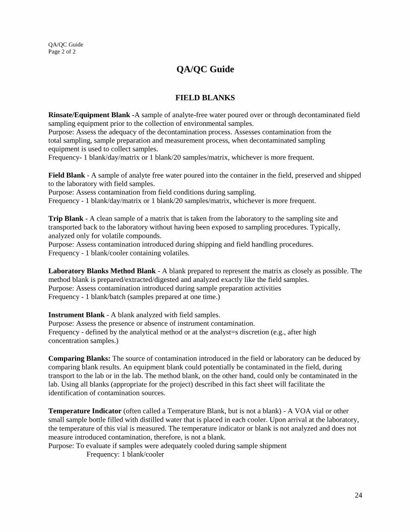
24
QA/QC Guide
Page 2 of 2
QA/QC Guide
FIELD BLANKS
Rinsate/Equipment Blank -A sample of analyte-free water poured over or through decontaminated field
sampling equipment prior to the collection of environmental samples.
Purpose: Assess the adequacy of the decontamination process. Assesses contamination from the
total sampling, sample preparation and measurement process, when decontaminated sampling
equipment is used to collect samples.
Frequency- 1 blank/day/matrix or 1 blank/20 samples/matrix, whichever is more frequent.
Field Blank - A sample of analyte free water poured into the container in the field, preserved and shipped
to the laboratory with field samples.
Purpose: Assess contamination from field conditions during sampling.
Frequency - 1 blank/day/matrix or 1 blank/20 samples/matrix, whichever is more frequent.
Trip Blank - A clean sample of a matrix that is taken from the laboratory to the sampling site and
transported back to the laboratory without having been exposed to sampling procedures. Typically,
analyzed only for volatile compounds.
Purpose: Assess contamination introduced during shipping and field handling procedures.
Frequency - 1 blank/cooler containing volatiles.
Laboratory Blanks Method Blank - A blank prepared to represent the matrix as closely as possible. The
method blank is prepared/extracted/digested and analyzed exactly like the field samples.
Purpose: Assess contamination introduced during sample preparation activities
Frequency - 1 blank/batch (samples prepared at one time.)
Instrument Blank - A blank analyzed with field samples.
Purpose: Assess the presence or absence of instrument contamination.
Frequency - defined by the analytical method or at the analyst=s discretion (e.g., after high
concentration samples.)
Comparing Blanks: The source of contamination introduced in the field or laboratory can be deduced by
comparing blank results. An equipment blank could potentially be contaminated in the field, during
transport to the lab or in the lab. The method blank, on the other hand, could only be contaminated in the
lab. Using all blanks (appropriate for the project) described in this fact sheet will facilitate the
identification of contamination sources.
Temperature Indicator (often called a Temperature Blank, but is not a blank) - A VOA vial or other
small sample bottle filled with distilled water that is placed in each cooler. Upon arrival at the laboratory,
the temperature of this vial is measured. The temperature indicator or blank is not analyzed and does not
measure introduced contamination, therefore, is not a blank.
Purpose: To evaluate if samples were adequately cooled during sample shipment
Frequency: 1 blank/cooler

25
Example Boring/Well Log
Well Log Header
Sample Log Borehole Log Well
Design Log
Sam
ple
#
OV
A/P
ID
Sp
l.
resu
lts
Den
sity
(blo
ws/
ft.
) Dep
th i
n
ft.
Dep
th i
n
feet
US
CS
Sy
mb
ol
Gra
ph
ic
Lo
g
Geologic Description (soil type, color, grain,
minor soil component, moisture, density,
odor, etc.)

26
Soil Classification Guide
Page 1 of 3
Soil Classification Guide

27
Soil Classification Guide Page 2 of 3

28
Soil Classification Guide Page 3 of 3

29
Example Data Tables
Well Gauging Data
June 25, 2008
Local ID
DNREC
Permit #
Depth to
GW
Depth to
LNAPL
LNAPL
Thickness
GW
Elevation
MW-1 123456 8.10 ND N/A 9.54
MW-2 123457 12.43 12.06 0.37 9.47
MW-3 123458 9.92 ND N/A 9.51
All distances in feet.
Local ID RBSL
<50 ft
RBSL
51-100 ft
RBSL
101-300
ft
MW-1
MW-2
MW-3
MW-4
Sample Date 6/26/2008 6/26/2008 6/26/2008 6/26/2008
Benzene 29 51 160
Toluene 7300 >520,000 >520,000
Ethylbenzene 3700 >630,000 >630,000
Total Xylenes 73000 >200,000 >200,000
MTBE 180 240 560
TBA N/A N/A N/A
Other Analytes
as Applicable
All concentrations in µg/L
Soil Sample Analytical Results
Local ID
RBSL
<50 ft
RBSL
<50 ft
SB-1
SB-2
SB-3
SB-4
Sample Date <50ft <50 ft 6/26/2008 6/26/2008 6/26/2008 6/26/2008
Sample Depth Soil GW Soil DC 10-11ft 11-12ft 6-7ft 7-8ft
Benzene 0.23 19
Toluene 210 3800
Ethylbenzene 350 2300
Total Xylenes >500 43,900
MTBE 0.13 200
TBA N/A N/A
Other Analytes
as Applicable
All concentrations in mg/Kg
Groundwater Analytical Results
Local ID Permit # RBSLs
MW-1 123456 <50'
Analyte
(RBSL)
Benzene
(29)
Toluene
(7,300)
Ethylbenzene
(3,700)
Total Xylenes
(73,000)
MTBE
(180)
DATE
Groundwater Sample Analytical
Results
Permit Local Screened
Number ID Interval
123456 MW-1 10-15ft
123456 MW-2 11-16ft
654321 MW-3 10-15ft
654321 MW-4 9-14ft

30
List of CSM Websites
http://www.ce.utexas.edu/prof/maidment/risk/lhwlect/scmv2/index.htm
http://www.epa.gov/region8/r8risk/hh_scm.html
http://www.co.sanmateo.ca.us/vgn/images/portal/cit_609/21/40/651311576Site%20Conceptual%20Mode
l.pdf
http://www.newmoa.org/cleanup/cwm/csm/HuntWhatIsTheCSM.pdf
http://www.emd.saccounty.net/Documents/presentations/Site%20Conceptual%20Model_files/frame.htm
http://www.triadcentral.org/mgmt/splan/sitemodel/index.cfm
http://www.dnr.mo.gov/env/hwp/tanks/siteconceptualmodelsmrbca.pdf
www.co.san-diego.ca.us/deh/water/docs/sam_kkezer_scm.ppt
http://www.epa.gov/athens/learn2model/part-two/onsite/i2l0_onsite.htm

31
Referenced ASTM Standards
D2488 Standard Practice for Description and Identification of Soils (Visual-Manual Procedure)
D5088 Practice for Decontamination of Field Equipment Used at Non-Radioactive Waste Sites
D5521 Guide for Development of Ground-Water Monitoring Wells in Granular Aquifers
D6452 Standard Guide for Purging Methods for Wells Used for Ground-Water Quality
Investigations
D6634 Guide for the Selection of Purging and Sampling Devices for Ground-Water Monitoring
Wells
D6771 Standard Practice for Low-Flow Purging and Sampling for Wells and Devices Used for
Ground-Water Quality Investigations