Hydrogenation-Assisted Graphene ARTICLE Origami...
25
ZHU AND LI VOL. 8 ’ NO. 3 ’ 2864–2872 ’ 2014 www.acsnano.org 2864 February 24, 2014 C 2014 American Chemical Society Hydrogenation-Assisted Graphene Origami and Its Application in Programmable Molecular Mass Uptake, Storage, and Release Shuze Zhu and Teng Li * Department of Mechanical Engineering and Maryland NanoCenter, University of Maryland, College Park, Maryland 20742, United States G raphene has emerged as an extra- ordinary material with its capability to accommodate an array of remark- able electronic, mechanical, and chemical properties. 13 Extra-large surface-to-volume ratio renders graphene a highly flexible morphology, giving rise to intriguing ob- servations such as ripples, wrinkles, and folds 48 as well as the potential to transform into other novel carbon nanostructures. 816 In particular, self-folding of graphene, 8 or graphene origami, 1719 has been subjected to intensive study due to the need to fabri- cate unconventional nanostructures via ap- proaches beyond conventional material preparation techniques. Progresses in pat- terning graphene with atomic-scale preci- sion have further paved the way toward achieving graphene origami in a program- mable fashion. 1823 For example, water nanodroplet can activate the self-folding of graphene flake cut in a particular cross shape. 8 The unique feature of such an un- conventional bottom-up nanomanufacture technique is that a material building block can self-assemble into a final folded struc- ture, which is typically energetically more favorable and thus more stable than the original building block. 24 In general, non- bonded adhesion, such as van der Waals (vdW) forces, plays a crucial role in over- coming the energy barrier (e.g., bending energy) in order to fold graphene as well as stabilizing the folded nanostructure against the perturbation from thermal fluc- tuation. A direct example is that a carbon nanoscroll can hold its spiral morphology rather stably via vdW forces distributed among interlayers over a large surface area. 816 On the other hand, manipulating or neutralizing the interlayer vdW interac- tion can significantly affect the morphology of the carbon nanoscroll because of its open and tunable topology. 25 By suitably pro- gramming the original graphene building blocks, the resulting folded nanostructures of graphene can be customized to take vari- ous unique morphology and topology that are otherwise impossible in conven- tional carbon nanostructures, such as carbon * Address correspondence to [email protected]. Received for review January 2, 2014 and accepted February 24, 2014. Published online 10.1021/nn500025t ABSTRACT The malleable nature of atomically thin graphene makes it a potential candidate material for nanoscale origami, a promising bottom-up nanomanufacturing approach to fabricating nanobuilding blocks of desirable shapes. The success of graphene origami hinges upon precise and facile control of graphene morphol- ogy, which still remains as a significant challenge. Inspired by recent progresses on functionalization and patterning of graphene, we demonstrate hydrogenation-assisted graphene origami (HAGO), a feasible and robust approach to enabling the formation of unconventional carbon nanostructures, through systematic molecular dynamics simulations. A unique and desirable feature of HAGO-enabled nanostructures is the programmable tunability of their morphology via an external electric field. In particular, we demonstrate reversible opening and closing of a HAGO-enabled graphene nanocage, a mechanism that is crucial to achieve molecular mass uptake, storage, and release. HAGO holds promise to enable an array of carbon nanostructures of desirable functionalities by design. As an example, we demonstrate HAGO-enabled high-density hydrogen storage with a weighted percentage exceeding the ultimate goal of US Department of Energy. KEYWORDS: graphene . origami . hydrogenation . self-assembly . nanomanufacture ARTICLE
Transcript of Hydrogenation-Assisted Graphene ARTICLE Origami...

ZHU AND LI VOL. 8 ’ NO. 3 ’ 2864–2872 ’ 2014
www.acsnano.org
2864
February 24, 2014
C 2014 American Chemical Society
Hydrogenation-Assisted GrapheneOrigami and Its Application inProgrammable Molecular MassUptake, Storage, and ReleaseShuze Zhu and Teng Li*
Department of Mechanical Engineering and Maryland NanoCenter, University of Maryland, College Park, Maryland 20742, United States
Graphene has emerged as an extra-ordinary material with its capabilityto accommodate an array of remark-
able electronic, mechanical, and chemicalproperties.1�3 Extra-large surface-to-volumeratio renders graphene a highly flexiblemorphology, giving rise to intriguing ob-servations such as ripples, wrinkles, andfolds4�8 aswell as the potential to transforminto other novel carbon nanostructures.8�16
In particular, self-folding of graphene,8 orgraphene origami,17�19 has been subjectedto intensive study due to the need to fabri-cate unconventional nanostructures via ap-proaches beyond conventional materialpreparation techniques. Progresses in pat-terning graphene with atomic-scale preci-sion have further paved the way towardachieving graphene origami in a program-mable fashion.18�23 For example, waternanodroplet can activate the self-foldingof graphene flake cut in a particular crossshape.8 The unique feature of such an un-conventional bottom-up nanomanufacturetechnique is that a material building block
can self-assemble into a final folded struc-ture, which is typically energetically morefavorable and thus more stable than theoriginal building block.24 In general, non-bonded adhesion, such as van der Waals(vdW) forces, plays a crucial role in over-coming the energy barrier (e.g., bendingenergy) in order to fold graphene as wellas stabilizing the folded nanostructureagainst the perturbation from thermal fluc-tuation. A direct example is that a carbonnanoscroll can hold its spiral morphologyrather stably via vdW forces distributedamong interlayers over a large surfacearea.8�16 On the other hand, manipulatingor neutralizing the interlayer vdW interac-tion can significantly affect the morphologyof the carbon nanoscroll because of its openand tunable topology.25 By suitably pro-gramming the original graphene buildingblocks, the resulting folded nanostructuresof graphene can be customized to take vari-ous unique morphology and topologythat are otherwise impossible in conven-tional carbon nanostructures, such as carbon
* Address correspondence [email protected].
Received for review January 2, 2014and accepted February 24, 2014.
Published online10.1021/nn500025t
ABSTRACT The malleable nature of atomically thin graphene
makes it a potential candidate material for nanoscale origami, a
promising bottom-up nanomanufacturing approach to fabricating
nanobuilding blocks of desirable shapes. The success of graphene
origami hinges upon precise and facile control of graphene morphol-
ogy, which still remains as a significant challenge. Inspired by recent
progresses on functionalization and patterning of graphene, we demonstrate hydrogenation-assisted graphene origami (HAGO), a feasible and robust
approach to enabling the formation of unconventional carbon nanostructures, through systematic molecular dynamics simulations. A unique and desirable
feature of HAGO-enabled nanostructures is the programmable tunability of their morphology via an external electric field. In particular, we demonstrate
reversible opening and closing of a HAGO-enabled graphene nanocage, a mechanism that is crucial to achieve molecular mass uptake, storage, and release.
HAGO holds promise to enable an array of carbon nanostructures of desirable functionalities by design. As an example, we demonstrate HAGO-enabled
high-density hydrogen storage with a weighted percentage exceeding the ultimate goal of US Department of Energy.
KEYWORDS: graphene . origami . hydrogenation . self-assembly . nanomanufacture
ARTIC
LE

ZHU AND LI VOL. 8 ’ NO. 3 ’ 2864–2872 ’ 2014
www.acsnano.org
2865
nanotube and fullerene. Such novel nanostructurescan overcome some intrinsic difficulties that the con-ventional carbon nanostructures would inevitably suf-fer for certain applications. For example, the hollownature of carbon nanotube26 and fullerene27 has mo-tivated the proposal of using such materials as hydro-gen storagemedium, yet the fact that large size carbonnanotubes and fullerene become structurally unstableposes a practical limitation on storage capacity. By con-trast, suitably folded graphene nanostructures canserve as nanocapsules or nanocontainers to host mo-lecular-scale cargo of desirable quantity,28,29 which hasprofound implications in molecular vessel and drugdelivery applications.30 For example, as to be shown inthis letter, a graphene nanocage can stably store hy-drogenmoleculeswith aweighted percentage of 9.7%,exceeding US Department of Energy (DOE)'s ultimategoal of 7.5%.31
The two-dimensional nature of graphene makes thechemical functionalization of graphene a promisingapproach tomodulating the graphene properties.32�38
For example, hydrogenation of graphene32,39,40 in-volves bonding atomic hydrogen to the carbon atomsin graphene. Such a reaction changes the hybridizationof graphene from sp2 into sp3. As a result, the two-dimensional atomic structure of pristine graphene isdistorted.10,11,41 Significant progresses have beenachieved on controllable hydrogenation of graphene.For example, single-sided hydrogenation of pristinegraphene has been theoretically and experimentallyexplored.10,11,32,41�47 Hybrid superlattices made ofpatterned hydrogenation can be fabricated in a con-trolled fashion on both macroscopic and microscopicscales.40 Recent studies show that hydrogen chemi-sorption in graphene can be enhanced by local curva-ture in a graphene sheet.45,48,49 It has also been shownthat a graphene sheet can closely conform to the sharpfeatures on a substrate surface (e.g., extrusions andedges),50�53 leading to large local curvature in thegraphene. These findings suggest the feasibility ofprecise hydrogenation (e.g., in atomic rows) of gra-phene in a programmable fashion. These advances onprogrammable bonding of atomic hydrogen to carbonatoms in pristine graphene open up new avenues formanipulating the morphology of graphene and there-fore exploring graphene-based novel nanomaterials. Inthis letter, we use molecular dynamics (MD) simula-tions to demonstrate the hydrogenation-assistedgraphene origami (HAGO), in which initially planar,suitably patterned graphene can self-assemble intothree-dimensional nanoscale objects of desirable geo-metric shapes. We further demonstrate that the HAGOprocess can be modulated by an external electric field,enabling programmable opening and closing of theresulting three-dimensional nano-objects, a desirablefeature to achieve molecular mass manipulation, stor-age, and delivery. To benchmark this unique feature,
we demonstrate using HAGO-enabled nanocagefor controllable uptake and release of fullerenes andnanoparticles as well as ultrahigh density of hydrogenstorage.
RESULTS AND DISCUSSION
Hydrogenation of a carbon atom in pristine gra-phene generates an sp3 carbon�hydrogen (C�H)bond, which induces a local structural change aroundthat carbon atom. The chemically adsorbed hydrogenatom attracts its bonded carbon atom while it repelsother neighboring carbon atoms. Therefore, the threeinitially planar carbon�carbon (C�C) bonds associatedwith the hydrogenated carbon atom would locallybend away from the hydrogen atom. If the grapheneis hydrogenated on both sides, the resulting hydro-genated graphene (termed as graphane32,39) wouldoverall remain a rather planarmorphology because thelocal distortions of the C�C bonds neutralize eachother. Nevertheless, if the graphene is single-sidedhydrogenated, the local distortion at each hydroge-nated carbon atom is accumulated.54 For example, ifhydrogenation lines are introduced in one side of agraphene, the accumulated distortion can effectivelyfold the graphene along the hydrogenation lines to acertain angle. Figure 1 shows that such a folding angleat equilibrium increases when the number of rows ofhydrogenation increases. In particular, it is found thatthe folding angle can be tailored to be close to 90� (e.g.,Figure 1(b,e)), which offers the possibility to potentiallyform a stable folded substructure that consists of twofaces that are folded nearly perpendicularly along thehydrogenation lines. The HAGO process often involvesa cascade of or simultaneous events of such foldingsteps, as to be shown below.Using MD simulations, we have successfully demon-
strated an array of unconventional nanostructuresenabled by HAGO, including hexahedral nanocage(Figure 2), octohedral nanocage, and nanobusket(Figures S1, S2, Supporting Information). In the simula-tions, the C�C and C�H bonds in the graphene as wellas the nonbonded C�C and C�H interactions aredescribed by AIREBO potential.55 The simulations arecarried out using Large-Scale Atomic/Molecular Mas-sively Parallel Simulator (LAMMPS).56 Figure 2(a) de-picts our simulation model to achieve HAGO-enabledhexahedral graphene nanocage. The double-crossshaped graphene flake is cut out of a rectangulargraphene with a length L = 13.2 nm and a width W =7.1 nm. Rows of single-sided hydrogenation are intro-duced along the expected edges, which demarcate thegraphene flake into nine regions. Hereinafter, eachsuch region is referred to as a graphene wall. Each ofthe six outer graphene walls (labeled 1�6) has threefree edges, and the center graphene wall (labeled 7)has only two free edges, while the remaining twographene walls (labeled 8 and 9) have no free edges.
ARTIC
LE

ZHU AND LI VOL. 8 ’ NO. 3 ’ 2864–2872 ’ 2014
www.acsnano.org
2866
Carbon atoms along the free edges of the grapheneflake are saturated by hydrogen atoms to avoid un-wanted bond formation during the self-assemblingprocess. Figure 2(b) shows the structural configurationafter the initial energy minimization (see Methodsand Movie M1 in Supporting Information). Figure 2(c)shows the further structural evolution (seeMovieM2 inSupporting Information). At 18 ps, all six outer gra-phene walls are in the process of bending upward,which later fold along the hydrogenated edges up toabout 90�. At 26 ps, the two graphene walls (labeled 8and 9) are in the process of bending upward, whichcauses the two sets of folded graphene walls (1�2�3and 4�5�6) to come close to each other, resemblingthe closing of a venus flytrap. At 40 ps, the two setsof folded graphene walls overlap with each other.Because of geometrical constraints and interwall vdWinteraction, an outer graphene wall on the left slides
above or beneath another outer graphene wallon the right. The vdW interaction further drives thetightening of the folded structure and serves as theinterwall adhesives to stabilize the final structure. Asa result, a quasicubic hexahedral graphene nanocageis formed.In practice, hydrogenation process of graphenemay
not be as perfect as the ideal case (e.g., Figure 2(a)). Inother words, defective hydrogenation (e.g., missinghydrogen atoms) could occur in a random fashion. Tothis end, we have carried out further simulations ofpatterned graphene with random imperfection in hy-drogenation. These further studies reveal that HAGO isa rather robust self-assembly process with a strongtolerance to possible imperfect hydrogenation. Forexample, we show that the graphene nanocage canstill be successfully formed even if only less than 70%of single-side hydrogenation from the ideal case isachieved (as detailed in Section IV in SupportingInformation).In the HAGO-enabled graphene nanocage, the inter-
wall vdW interaction energy plays a key role in main-taining the nanocage structural stability. Therefore,manipulation of such an interaction energy potentiallyoffers the morphological tunability of the graphenenanocage (e.g., controllable opening and closing). Wenext show that an external electric field can effectivelyreduce the interwall adhesion. Therefore, by tuning theexternal electric field, facile control of the morphologyof graphene nanocage can be achieved. An externalelectric field can cause the polarization of carbonatoms in graphene. As a result, the intergraphene-layerinteraction can be changed. For example, it is shownthat an electric field can effectively cause the radial ex-pansion of a carbon nanoscroll due to the polarization-induced decrease of intergraphene-layer adhesion.25
Recently first-principle calculations have revealedthe dependence of the effective dielectric constantin graphene structures on external electric field.57,58
For a graphene bilayer, both in-plane and out-of-plane
Figure 1. Top view and side view of graphene structures folded to an angle due to single-sided hydrogenation along variouslines at equilibrium. (a) One-line and (b) two-line hydrogenation are introduced along zigzag direction of graphene lattice,respectively. (c�e): One-line, two-line, and three-line hydrogenation are introduced along arm-chair direction of graphenelattice, respectively. The bottom row plots the variation of the folding angle at 300 K over time, which is shown to beminimum, indicating robust stability of the folded substructure.
Figure 2. (a) Double-cross shaped graphene flake toachieve HAGO-enabled hexahedral graphene nanocage.Insets show the hydrogenation lines, which demarcate thegraphene flake into nine regions (labeled by numbers). (b)Energy-minimized structure by conjugate gradient (CG) andsteepest descent algorithm. (c) Further energy minimiza-tion toward the formation of a graphene nanocage.
ARTIC
LE
ZHU AND LI VOL. 8 ’ NO. 3 ’ 2864–2872 ’ 2014
www.acsnano.org
2867
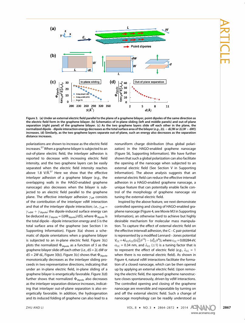
polarizations are shown to increase as the electric fieldincreases.57When a graphene bilayer is subjected to anout-of-plane electric field, the interlayer adhesion isreported to decrease with increasing electric fieldintensity, and the two graphene layers can be easilyseparated when the electric field intensity reachesabove 1.8 V/Å.57 Here we show that the effectiveinterlayer adhesion of a graphene bilayer (e.g., theoverlapping walls in the HAGO-enabled graphenenanocage) also decreases when the bilayer is sub-jected to an electric field parallel to the grapheneplane. The effective interlayer adhesion γeff consistsof the contribution of the interlayer vdW interactionand that of the interlayer dipole interaction; i.e., γeff =γvdW þ γdipole; the dipole-induced surface energy canbe deduced as γdipole = ((dΦdipole)/dS), whereΦdipole isthe total dipole�dipole interaction energy and S is thetotal surface area of the graphene (see Section I inSupporting Information). Figure 3(a) shows a sche-matic of dipole orientations when a graphene bilayeris subjected to an in-plane electric field. Figure 3(c)plots the normalized Φdipole as a function of S as thegraphene bilayer slide off each other (i.e., dS= 2L dW ordS = 2W dL, Figure 3(b)). Figure 3(c) shows thatΦdipole
monotonically decreases as the interlayer sliding pro-ceeds in two representative directions, indicating thatunder an in-plane electric field, in-plane sliding of agraphene bilayer is energetically favorable. Figure 3(d)further shows that normalized Φdipole also decreasesas the interlayer separation distance increases, indicat-ing that interlayer out-of-plane separation is also en-ergetically favorable. In addition, the hydrogenationand its induced folding of graphene can also lead to a
nonuniform charge distribution (thus global polari-zation) in the HAGO-enabled graphene nanocage(Figure S6, Supporting Information). We have furthershown that such a global polarization can also facilitatethe opening of the nanocage when subjected to anexternal electric field (See Section V in SupportingInformation). The above analysis suggests that anexternal electric field can reduce the effective interwalladhesion in a HAGO-enabled graphene nanocage, aunique feature that can potentially enable facile con-trol of the morphology of graphene nanocage via
tuning the external electric field.Inspired by the above feature, we next demonstrate
controlled opening and closing of HAGO-enabled gra-phene nanocage (Figure 4, seeMovieM3 in SupportingInformation), an otherwise hard to achieve but highlydesirable mechanism for molecular mass manipula-tion. To capture the effect of external electric field onthe effective interwall adhesion, the C�C pair potentialis represented by a modified Lennard�Jones potentialVCC=4λCCεCC((σCC
12/r12)� (σCC6 /r6)),where εCC=0.00284eV,
σCC = 0.34 nm, and λCC (e1) is a tuning factor that isto represent the effect of electric field (e.g., λCC = 1when there is no external electric field). As shown inFigure 4, natural vdW interactions facilitate the forma-tion of a closed nanocage, which can be then openedup by applying an external electric field. Upon remov-ing the electric field, the opened graphene nanostruc-ture closes spontaneously, driven by vdW interactions.The controlled opening and closing of the graphenenanocage are reversible and repeatable by turning onand off the external electric field. Such a change ofnanocage morphology can be readily understood as
Figure 3. (a) Under an external electric field parallel to the plane of a graphene bilayer, point dipoles of the same direction asthe electric field form in the graphene bilayer. (b) Schematics of in-plane sliding (left and middle panels) and out-of-planeseparation (right panel) of the graphene bilayer. (c) As the two graphene layers slide off each other in the plane, thenormalizeddipole�dipole interaction energydecreases as the total surface area of the bilayer (e.g., 2(LþdL)Wor 2L(WþdW))increases. (d) Similarly, as the two graphene layers separate out-of-plane, such an energy also decreases as the separationdistance increases.
ARTIC
LE

ZHU AND LI VOL. 8 ’ NO. 3 ’ 2864–2872 ’ 2014
www.acsnano.org
2868
follows. In the HAGO-enabled formation of graphenenanocage, the closing of the nanocage leads tothe decrease of interwall vdW interaction energy,which counterbalances the increase of folding in-duced bending energy. On the other hand, sub-jected to a sufficiently strong electric field, theeffective interwall adhesion decreases, to some ex-tent that is not able to hold up the nanocage. As aresult, the nanocage opens up to relax the excessivebending energy.The controlled opening and closing of such gra-
phene nanocages have practical significance, e.g., to beused as a nanovessel or nanocontainer to achievemolecular mass delivery.28�30 As a demonstration ofsuch a functionality, we study the uptake and releaseof C60 molecules using a HAGO-enabled graphenenanocage. A closed nanocage is first immersed intoa reservoir of C60 molecules, as shown in Figure 5(a)(see Movie M4 in Supporting Information). The MD
simulation using AIREBO potential is carried out withNVT ensemble at a temperature of 300 K.Reflective wall boundary condition is imposed in all
three dimensions of the simulation box to simulate aconstant feed of C60 molecules. Initially, C60 moleculesevolve to adhere to the outer surface of the graphenenanocage because of vdW adhesion. When an electricfield is applied (e.g., λCC decreases from 1 to 0.12), thenanocage opens up. Driven by thermal noise, some C60molecules could migrate into the inner space of thenanocage. Upon turning off the electric field, thenanocage closes spontaneously, and these C60 mol-ecules are uptaken and stored inside the nano-cage (Figure 5(a�d), see Movie M4 in SupportingInformation). After the nanocage with the cargo load(e.g., C60) is transported to a designated destination,release of the cargo load can be achieved by applyingan electric field to open up the nanocage, followed bythemigration of the C60molecules out of the nanocage
Figure 4. Controlled opening and closing of graphene nanocage via tuning effective interwall adhesion. λCC = 1: withoutapplied electric field, nanocage is closed; λCC = 0.12: under an applied electric field, interwall adhesion decreases, leading tothe opening of the nanocage under thermal fluctuation. The simulation is done in the NVT ensemble at 300 K.
Figure 5. (a�d) Controlled opening and closing of a graphene nanocage immersed in a C60 reservoir can enable the uptake ofC60 molecules by the nanocage. (e�h) After the cargo-loaded nanocage is transported to the destination, the stored C60molecule can be released by the electric field induced opening of the nanocage. (i�l) Release of a silicon nanoparticle from agraphene nanocage under the same mechanism.
ARTIC
LE

ZHU AND LI VOL. 8 ’ NO. 3 ’ 2864–2872 ’ 2014
www.acsnano.org
2869
driven by thermal fluctuation (Figure 5(e�h), see MovieM5 in Supporting Information). We have also demon-strated the uptake and release of other molecular mass(e.g., silicon nanoparticles, Figure 5(i�l)) using theHAGO-enabled graphene nanocage under the samemechanisms. Note that, despite thepossible uncertaintyof the thermally driven process, programmable uptake,storage, and release of molecular mass could be im-plemented by controlling a large amount of HAGO-enabled graphene nanocages via a global electric field.An external electric field can also facilitate the for-
mation of graphene nanocages of large sizes that areotherwise challenging to achieve. Figure 6 shows theelectric field assisted formation of a graphene nano-cagewith a size of 9 nmby 9 nmby 12 nm. Figure 6(a,b)shows two snapshots during the energy minimizationprocess. When the graphene flake becomes larger, itbecomes easier to fluctuate out-of-plane. As a result,neighboring graphene walls evolve to partially attachto each other driven by vdW adhesion, preventing thedesirable formation of a nanocage. Such an unwantedfeature can be overcome by the help of externalelectric field. As shown in Figure 6(d�f), upon applyingan electric field followed by turning it off, the initiallycollapsed graphene structure first partially opens upand finally folds up into a rather regular hexahedronnanocage (see Movie M6 in Supporting Information).The effect of the electric field in such a process can beunderstood as follows. In the presence of an electricfield, the effective interwall adhesion decreases, whichcannot balance the excessive bending energy in theinitially collapsed and distorted graphene structure.
As a result, the entire graphene structure first partiallyopens up to release excessive bending energy andthen gradually evolves toward lower energy config-uration (Figure 6(d,e)). After such a priming processand followed by restoring the natural interwall vdWadhesion by turning off the electric field, the graphenestructure finally evolves into a regular nanocage asdesired, which corresponds to the lowest energy levelas shown in Figure 6(g). In otherwords, the electric fieldcan help prevent the graphene structure getting stuckin unwanted metastable states and thus facilitate theformation of the thermodynamically stable graphenenanostructure. Results in Figure 6 further demon-strate the feasibility and robustness of the program-mable HAGO process.The tunable and robust morphology HAGO-enabled
graphene nanocage as well as its hollow nature with avolumetric capacity of nearly 1000nm3 (e.g., Figure 6(f))render attractive attributes for potential applicationssuch as nanoscale pressure tank.26,27 To benchmarksuch potentials, here we demonstrate high density hy-drogen storage enabled by graphene. Giant fullereneshave been proposed to serve as a medium of highdensity hydrogen storage,27 but their closed natureposes an intrinsic challenge to uptake and releasehydrogen, as such a processes involve breaking cova-lent C�C bonds and thus are irreversible. By contrast, aHAGO-enabled graphene nanocage can be repeatedlyopened and closed via facile control of an externalelectric field, making reversible uptake and release ofhydrogen feasible. Although the graphene nanocageis not fully sealed by covalent bonds as in a giant
Figure 6. (a) Patterned graphene is suitably hydrogenated to form a graphene nanocage of large size. (b) Morphology afterinitial energy minimization. (c�f) Electric field assisted formation of large size graphene nanocage. (g) Evolution of potentialenergy from (b�f), indicating that the electric field can help prevent the graphene nanostructure trapped in unwantedmetastable state (c) and facilitate the formation of the final nanocage (f), a thermodynamically stable state.
ARTIC
LE

ZHU AND LI VOL. 8 ’ NO. 3 ’ 2864–2872 ’ 2014
www.acsnano.org
2870
fullerene, the interwall adhesion over large areas in-deed allows it to sustain sufficiently high pressure (thusstore a large amount of hydrogen molecules inside). Inaddition, when an empty nanocage is immersed in ahydrogen reservoir, a slight opening of the nanocageeffectively gives rise to the formation of gaps or poresalong the edge and corner of the nanocage, a featurethat allows the adsorption of hydrogen atoms into theinner volume of the nanocage (See Section VI inSupporting Information).59,60
As shown in Figure 7(a) (seeMovie M7 in SupportingInformation), the graphene nanocage in Figure 6 canhost 47 880 hydrogen atoms in its inner volume at atemperature of 70 K. During the MD simulation, noescaping of the hydrogen is observed at such a tem-perature. The graphene nanocage contains 37 130carbon atoms and 1468 initially chemically adsorbedhydrogen atoms. Therefore, the weighted percentageof the hydrogen storage is about 9.7%, which exceedsthe US DOE target of 5.5% for the year 2017 and theultimate goal of 7.5%,31 indicating the promising po-tential of HAGO-enabled graphene nanocage as a highdensity hydrogen storage medium. The hydrogenstorage density using graphene nanocage dependson the nanocage size, which can be estimated by asimple model. Consider a cubic graphene nanocageformed viaHAGOprocesswith side length of L, let Fcbethe area density of graphene, Fh be the volume densityof the stored hydrogen, mh and mc be the atomicmass of hydrogen and carbon atoms, respectively.The weighted percentage of hydrogen storage insuch a graphene nanocage can be estimated by((mhFhL3)/(mhFhL3 þ 9mcFcL2)). Figure 7(b) plots the
weighted percentage of hydrogen storage as a func-tion of graphene nanocage size L, for four differenthydrogen volume density. As shown in Figure 7(b), thehydrogen storage capacity increases as the graphenenanocage size increases, in an approximately linearfashion. For example, to reach the DOE's ultimate goalfor hydrogen storage density, graphene nanocages ofsize greater than 12 and 6 nm are needed, for thehydrogen volume density of 30 and 60 atom/nm3,respectively. We have also shown that such hydrogenvolume density levels can be feasibly achieved bytuning the ambient hydrogen reservoir pressure (seeSection VI in Supporting Information). In this sense, theabove estimation offers a rule-of-thumb guideline forthe design of graphene nanocage to achieve certainhydrogen storage density. The hydrogen atoms storedinside the graphene nanocage can also be effectivelyreleased by elevating the temperature (details avail-able in Section VII in Supporting Information).
CONCLUSIONS
In summary, through systematic MD simulations, wedemonstrate a feasible and robust hydrogenation-assisted graphene origami (HAGO) process. We furtherreveal that a HAGO-enabled graphene nanocage canbe reversibly opened and closed in a programmablefashion via the facile control of an external electric field,a desirable feature that can enable controllable mo-lecular mass uptake, storage, and release, as well ashigh density hydrogen storage. These promising ap-plications of HAGO process and HAGO-enabled novelnanostructures call for further experimental investiga-tions to explore their full potential.
METHODS
C�C and C�H bonds in the graphene as well as the non-bonded C�C and C�H interactions are described by AIREBOpotential.55 The simulations are carried out using Large-Scale
Atomic/Molecular Massively Parallel Simulator (LAMMPS).56 Thetime step for all simulations is set to be 0.5 femtoseconds (fs).Molecular dynamics simulations in Figure 1, Figure 4, Figure 5,and Figure 6(c�f) are done in NVT ensemble at 300 K and byNose�Hoover thermostat. Molecular dynamics simulations in
Figure 7. (a) High density hydrogen storage in HAGO-enabled graphene nanocage, with a weighted percentage of 9.7%,beyond the US DOE ultimate goal of 7.5% for hydrogen storage. For visual clarity, only half of the nanocage is shown. SeeMovieM7 in Supporting Information. (b)Weighted percentage of hydrogen storage in HAGO-enabled graphene nanocage asa function of the side length of a cubic graphene nanocage, for four different hydrogen volumedensities inside the nanocage.Dashed lines denote US DOE ultimate goal and year 2017 goal on hydrogen storage density.
ARTIC
LE

ZHU AND LI VOL. 8 ’ NO. 3 ’ 2864–2872 ’ 2014
www.acsnano.org
2871
Figure 7(a) are done in NVT ensemble at 70 K and by Nose�Hoover thermostat. Figure 2 is to demonstrate that HAGO isintrinsically energetically favorable; therefore, energy minimi-zation simulations are done in NVE ensemble (not NVT) inFigure 2. Energy minimization simulations in Figure 2 (also inFigure 6(a,b)) are first done by conjugate gradient (CG) algo-rithm followed by steepest descent algorithm until either thetotal energy change between successive iterations dividedby the energy magnitude is less than or equal to 10�10 or thetotal force is less than 10�5 eV Å�1. However, both conjugategradient and steepest descent algorithm are highly possible tofind a local energy minimum point. To gain further approach toglobal energyminimum configuration, we adopted an alternateway of relaxing a system by running dynamics with a small orlimited time step.56 The simulation is then running in NVEensemble with the restriction that the maximum distance anatom can move in one time step is 0.1 Å. The time step is set tobe 0.5 fs.
Conflict of Interest: The authors declare no competingfinancial interest.
Acknowledgment. This research is supported by the Na-tional Science Foundation (Grant Numbers: 1069076 and1129826). Z.S. is thankful for the support of the Clark SchoolFuture Faculty Program at the University of Maryland.
Supporting Information Available: Details of theoreticalmethod, other forms of HAGO-enabled nanostructures, effectof imperfection in hydrogenation pattern, effect of globalpolarization, hydrogen adsorption into graphene nanocage,and temperature-modulated hydrogen release. Supporting fig-ures and videos. This material is available free of charge via theInternet at http://pubs.acs.org.
REFERENCES AND NOTES1. Geim, A.; Novoselov, K. The Rise of Graphene. Nat. Mater.
2007, 6, 183–191.2. Klimov, N. N.; Jung, S.; Zhu, S.; Li, T.; Wright, C. A.; Solares,
S. D.; Newell, D. B.; Zhitenev, N. B.; Stroscio, J. A. Electro-mechanical Properties of Graphene Drumheads. Science2012, 336, 1557–1561.
3. Lee, C.; Wei, X.; Kysar, J.; Hone, J. Measurement of theElastic Properties and Intrinsic Strength of MonolayerGraphene. Science 2008, 321, 385–388.
4. Fasolino, A.; Los, J.; Katsnelson, M. Intrinsic Ripples inGraphene. Nat. Mater. 2007, 6, 858–861.
5. Zhu, S.; Galginaitis, J.; Li, T. Critical Dispersion Distance ofSilicon Nanoparticles Intercalated Between GrapheneLayers. J. Nanomater. 2012, 375289(1)–375289(4), DOI:10.1155/2012/375289.
6. Li, T. Extrinsic Morphology of Graphene. Modell. Simul.Mater. Sci. Eng. 2011, 19, 054005(1)–054005(15).
7. Kim, K.; Lee, Z.; Malone, B.; Chan, K.; Aleman, B.; Regan, W.;Gannett, W.; Crommie, M.; Cohen, M.; Zettl, A. MultiplyFolded Graphene. Phys. Rev. B: Condens. Matter Mater.Phys. 2011, 83, 245433(1)–245433(8).
8. Patra, N.; Wang, B.; Kral, P. Nanodroplet Activated andGuided Folding of Graphene Nanostructures. Nano Lett.2009, 9, 3766–3771.
9. Zhang, Z.; Li, T. Carbon Nanotube Initiated Formation ofCarbon Nanoscrolls. Appl. Phys. Lett. 2010, 97, 081909(1)–081909(3).
10. Zhu, S.; Li, T. Hydrogenation Enabled Scrolling of Graphene.J. Phys. D: Appl. Phys. 2013, 46, 075301(1)–075301(8).
11. Yu, D.; Liu, F. Synthesis of Carbon Nanotubes by Rolling upPatterned Graphene Nanoribbons Using Selective AtomicAdsorption. Nano Lett. 2007, 7, 3046–3050.
12. Zhang, Z.; Li, T. Ultrafast Nano-Oscillators Based on Inter-layer-Bridged Carbon Nanoscrolls. Nanoscale Res. Lett.2011, 6, 470(1)–470(11).
13. Shi, X.; Pugno, N.; Gao, H. Tunable Core Size of CarbonNanoscrolls. J. Comput. Theor. Nanosci. 2010, 7, 517–521.
14. Xie, X.; Ju, L.; Feng, X.; Sun, Y.; Zhou, R.; Liu, K.; Fan, S.; Li, Q.;Jiang, K. Controlled Fabrication of High-Quality Carbon
Nanoscrolls fromMonolayer Graphene.Nano Lett. 2009, 9,2565–2570.
15. Braga, S.; Coluci, V.; Legoas, S.; Giro, R.; Galvao, D.; Baugh-man, R. Structure and Dynamics of Carbon Nanoscrolls.Nano Lett. 2004, 4, 881–884.
16. Martins, B.; Galvao, D. Curved Graphene Nanoribbons:Structure and Dynamics of Carbon Nanobelts. Nanotech-nology 2010, 21, 075710(1)–075710(6).
17. Siegel, J. Materials Chemistry: Carbon Origami. Nature2012, 486, 327–328.
18. Feng, J.; Li, W.; Qian, X.; Qi, J.; Qi, L.; Li, J. Patterning ofGraphene. Nanoscale 2012, 4, 4883–4899.
19. Qi, J.; Huang, J.; Feng, J.; Shi, D.; Li, J. The Possibility ofChemically Inert, Graphene-Based All-Carbon ElectronicDevices with 0.8 eV Gap. ACS Nano 2011, 5, 3475–3482.
20. Bell, D.; Lemme, M.; Stern, L.; Williams, J. R.; Marcus, C.Precision Cutting and Patterning of Graphenewith HeliumIons. Nanotechnology 2009, 20, 455301(1)–455301(5).
21. Ci, L.; Xu, Z.; Wang, L.; Gao, W.; Ding, F.; Kelly, K.; Yakobson,B.; Ajayan, P. Controlled Nanocutting of Graphene. NanoRes. 2008, 1, 116–122.
22. Ci, L.; Song, L.; Jariwala, D.; Elias, A.; Gao, W.; Terrones, M.;Ajayan, P. Graphene Shape Control by Multistage Cuttingand Transfer. Adv. Mater. 2009, 21, 4487–4491.
23. Fischbein, M.; Drndic, M. Electron Beam Nanosculpting ofSuspended Graphene Sheets. Appl. Phys. Lett. 2008, 93,113107(1)–113107(3).
24. Whitesides, G. Nanoscience, Nanotechnology, and Chem-istry. Small 2005, 1, 172–179.
25. Shi, X.; Cheng, Y.; Pugno, N.; Gao, H. Tunable Water Chan-nels with Carbon Nanoscrolls. Small 2010, 6, 739–744.
26. Chen, H.; Sun, D.; Gong, X.; Liu, Z. Self-Assembled WaterMolecules as a Functional Valve for a High-Pressure Nano-container. Angew. Chem., Int. Ed. 2013, 52, 1973–1976.
27. Pupysheva, O.; Farajian, A.; Yakobson, B. Fullerene Nano-cage Capacity for Hydrogen Storage. Nano Lett. 2008, 8,767–774.
28. Chen, Y.; Guo, F.; Jachak, A.; Kim, S.; Datta, D.; Liu, J.; Kulaots,I.; Vaslet, C.; Jang, H.; Huang, J.; Kane, A.; Shenoy, V.; Hurt, R.Aerosol Synthesis of Cargo-Filled Graphene Nanosacks.Nano Lett. 2012, 12, 1996–2002.
29. Chen, Y.; Guo, F.; Qiu, Y.; Hu, H.; Kulaots, I.; Walsh, E.; Hurt, R.Encapsulation of Particle Ensembles in Graphene Nano-sacks as a New Route to Multifunctional Materials. ACSNano 2013, 7, 3744–3753.
30. Fernandes, R.; Gracias, D. Self-Folding Polymeric Contain-ers for Encapsulation and Delivery of Drugs. Adv. DrugDelivery Rev. 2012, 64, 1579–1589.
31. DOE, Office of Energy Efficiency and Renewable Energy(EERE). http://www1.eere.energy.gov/hydrogenandfuelcells/storage/pdfs/targets_onboard_hydro_storage.pdf, 2009.
32. Elias, D.; Nair, R.; Mohiuddin, T.; Morozov, S.; Blake, P.;Halsall, M.; Ferrari, A.; Boukhvalov, D.; Katsnelson, M.; Geim,A.; Novoselov, K. Control of Graphene's Properties byReversible Hydrogenation: Evidence for Graphane. Science2009, 323, 610–613.
33. Xu, Y.; Bai, H.; Lu, G.; Li, C.; Shi, G. Flexible Graphene Filmsvia the Filtration of Water-Soluble Noncovalent Function-alized Graphene Sheets. J. Am. Chem. Soc. 2008, 130,5856–5857.
34. Ryu, S.; Han,M.;Maultzsch, J.; Heinz, T.; Kim, P.; Steigerwald,M.; Brus, L. Reversible Basal Plane Hydrogenation ofGraphene. Nano Lett. 2008, 8, 4597–4602.
35. Wang, X.; Tabakman, S.; Dai, H. Atomic Layer Deposition ofMetal Oxides on Pristine and Functionalized Graphene.J. Am. Chem. Soc. 2008, 130, 8152–8153.
36. Boukhvalov, D.; Katsnelson, M. Chemical Functionalizationof Graphene with Defects. Nano Lett. 2008, 8, 4373–4379.
37. Boukhvalov, D.; Katsnelson, M.; Lichtenstein, A. Hydrogenon Graphene: Electronic Structure, Total energy, Struc-tural Distortions and Magnetism from First-PrinciplesCalculations. Phys. Rev. B: Condens. Matter Mater. Phys.2008, 77, 035427(1)–035427(7).
38. Balog, R.; Jorgensen, B.; Nilsson, L.; Andersen, M.; Rienks, E.;Bianchi, M.; Fanetti, M.; Laegsgaard, E.; Baraldi, A.; Lizzit, S.;
ARTIC
LE

ZHU AND LI VOL. 8 ’ NO. 3 ’ 2864–2872 ’ 2014
www.acsnano.org
2872
Sljivancanin, Z.; Besenbacher, F.; Hammer, B.; Pedersen, T.;Hofmann, P.; Hornekaer, L. Bandgap Opening in GrapheneInduced by Patterned Hydrogen Adsorption. Nat. Mater.2010, 9, 315–319.
39. Sofo, J.; Chaudhari, A.; Barber, G. Graphane: A Two-Dimen-sional Hydrocarbon. Phys. Rev. B: Condens. Matter Mater.Phys. 2007, 75, 153401(1)–153401(4).
40. Sun, Z.; Pint, C.; Marcano, D.; Zhang, C.; Yao, J.; Ruan, G.; Yan,Z.; Zhu, Y.; Hauge, R.; Tour, J. TowardsHybrid Superlattices inGraphene. Nat. Commun. 2011, 2, 559(1)–559(5).
41. Reddy, C.; Zhang, Y.; Shenoy, V. Patterned Graphone;ANovel Template for Molecular Packing. Nanotechnology2012, 23, 165303(1)–165303(5).
42. Pujari, B.; Gusarov, S.; Brett, M.; Kovalenko, A. Single-Side-Hydrogenated Graphene: Density Functional Theory Pre-dictions. Phys. Rev. B: Condens. Matter Mater. Phys. 2011,84, 041402(R)(1)–041402(R)(4).
43. Zhou, J.; Wang, Q.; Sun, Q.; Chen, X.; Kawazoe, Y.; Jena, P.Ferromagnetism in Semihydrogenated Graphene Sheet.Nano Lett. 2009, 9, 3867–3870.
44. Sessi, P.; Guest, J.; Bode, M.; Guisinger, N. PatterningGraphene at the Nanometer Scale via Hydrogen Desorp-tion. Nano Lett. 2009, 9, 4343–4347.
45. Chernozatonskii, L.; Sorokin, P. Nanoengineering Struc-tures on Graphene with Adsorbed Hydrogen “Lines”.J. Phys. Chem. C 2010, 114, 3225–3229.
46. Zhang, H.; Miyamoto, Y.; Rubio, A. Laser-Induced Preferen-tial Dehydrogenation of Graphane. Phys. Rev. B: Condens.Matter Mater. Phys. 2012, 85, 201409(R)(1)–201409(R)(4).
47. Zhou, J.; Sun, Q. How to Fabricate a SemihydrogenatedGraphene Sheet? A Promising Strategy Explored. Appl.Phys. Lett. 2012, 101, 073114(1)–073114(4).
48. Tada, K.; Furuya, S.; Watanabe, K. Ab Initio Study of Hydro-gen Adsorption to Single-Walled Carbon Nanotubes. Phys.Rev. B: Condens. Matter Mater. Phys. 2001, 63, 155405(1)–155405(4).
49. Ruffieux, P.; Groning, O.; Bielmann, M.; Mauron, P.;Schlapbach, L.; Groning, P. Hydrogen Adsorption on Sp2-Bonded Carbon: Influence of the Local Curvature. Phys.Rev. B: Condens. Matter Mater. Phys. 2002, 66, 245416(1)–245416(8).
50. Lui, C.; Liu, L.; Mak, K.; Flynn, G.; Heinz, T. Ultraflat Graphene.Nature 2009, 462, 339–341.
51. Ishigami, M.; Chen, J.; Cullen, W.; Fuhrer, M.; Williams, E.Atomic Structure of Graphene on SiO2. Nano Lett. 2007, 7,1643–1648.
52. Zhu, S.; Li, T. Wrinkling Instability of Graphene on Sub-strate-Supported Nanoparticles. J. Appl. Mech. 2014, 81,061008(1)–061008(5).
53. Yamamoto, M.; Pierre-Louis, O.; Huang, J.; Fuhrer, M.;Einstein, T.; Cullen, W. “The Princess and the Pea” at theNanoscale: Wrinkling and Delamination of Graphene onNanoparticles. Phys. Rev. X 2012, 2, 041018(1)–041018(11).
54. Zhang, Z.; Liu, B.; Hwang, K.; Gao, H. Surface-Adsorption-Induced Bending Behaviors of Graphene Nanoribbons.Appl. Phys. Lett. 2011, 98, 121909(1)–121909(3).
55. Stuart, S.; Tutein, A.; Harrison, J. A Reactive Potential forHydrocarbons with Intermolecular Interactions. J. Chem.Phys. 2000, 112, 6472–6486.
56. Plimpton, S. Fast Parallel Algorithms for Short-RangeMolecular-Dynamics. J. Comput. Phys. 1995, 117, 1–19.
57. Santos, E.; Kaxiras, E. Electric-Field Dependence of theEffective Dielectric Constant in Graphene. Nano Lett.2013, 13, 898–902.
58. Santos, E. Magnetoelectric Effect in Functionalized Few-Layer Graphene. Phys. Rev. B: Condens. Matter Mater. Phys.2013, 87, 155440(1)–155440(7).
59. Gogotsi, Y.; Dash, R.; Yushin, G.; Yildirim, T.; Laudisio, G.;Fischer, J. Tailoring of Nanoscale Porosity in Carbide-Derived Carbons for Hydrogen Storage. J. Am. Chem.Soc. 2005, 127, 16006–16007.
60. Yushin, G.; Dash, R.; Jagiello, J.; Fischer, J.; Gogotsi, Y.Carbide-Derived Carbons: Effect of Pore Size on HydrogenUptake and Heat of Adsorption. Adv. Funct. Mater. 2006,16, 2288–2293.
ARTIC
LE

S1
Supporting Information
Hydrogenation Assisted Graphene Origami and Its Application in Programmable
Molecular Mass Uptake, Storage, and Release
Shuze Zhu, Teng Li*
Department of Mechanical Engineering and Maryland NanoCenter, University of Maryland,
College Park, MD 20742
*Corresponding author: [email protected]
I. Dipole-dipole interaction
The dipole-dipole interactionsS1 can be described as V(r⃗ij) =1
4πϵ0|r⃗⃗ij|3 [|p⃗⃗i||p⃗⃗j| −
3(r⃗⃗ij.p⃗⃗⃗i)(r⃗⃗ij.p⃗⃗⃗j)
|r⃗⃗ij|2 ],
where r⃗ij is the distance between dipole i and dipole j, p⃗⃗i = 4πϵ0αiE⃗⃗⃗ the induced dipole mement,
E⃗⃗⃗ the applied electric field, ϵ0 the vacuum permittivity, and αi the polarizability of atom i .
Assume E⃗⃗⃗ = (Ex, 0,0) and the carbon planes are in parallel with the electric field. Only the
dipole-dipole interaction between two layers is considered because they are expected to act
against the vdW adhesion the most. Let r⃗ij = (xj − xi, yj − yi, zj − zi) and assuming constant
polarizability for each carbon atomαi = αj = α, we have
V(r⃗ij) =4πϵ0α2Ex
2
((xi−xj)2
+(yi−yj)2
+d2)
32
−12πϵ0α2Ex
2(xj−xi)2
((xi−xj)2
+(yi−yj)2
+d2)
52
, where d denotes the interlayer spacing.
The total dipole-dipole interaction energy is Φdipole = ∑ V(r⃗ij)i≠j , from which the dipole-
induced surface energy can be deduced as γdipole =dΦdipole
dS=
dΦdipole
2(WdL+LdW). The total dipole-
dipole interaction energy can be calculated as

S2
Φdipole = λxλy ∫ ∫ ∫ ∫4πϵ0α2Ex
2
((x1 − x2)2 + (y1 − y2)2 + d2)32
y2max
y2min
y1max
y1min
x2max
x2min
x1max
x1min
−12πϵ0α2Ex
2(x2 − x1)2
((x1 − x2)2 + (y1 − y2)2 + d2)52
dx1dx2 dy1dy2
where λxand λy are the dipole density along x and y direction.
II. Formation of octohedral nanocage
We demonstrate the HAGO-enabled formation of octahedral graphene nanocage. A graphene
bilayer is patterned into a shape with four triangular flaps and its outer surface is suitably
hydrogenated, as shown in Figure S1 (a). Different from those in the case of forming hexahedron
graphene nanocage, all free edges in the graphene bilayer are not saturated by hydrogen atoms to
allow the desirable bonding formation to seal the edges. The initial separation distance between
the two graphene layers is 0.34 nm and the simulation is carried out with Canonical Ensemble at
a temperature of 900K to facilitate the covalent bonding formation between neighboring free
edges. Single-sided hydrogenation in the center region leads to accumulated distortion of each
graphene layer (Figure S1 (b)). As a result, the center region of each graphene layer bulges out
and separate, causing the four triangle flaps in the top graphene layer curve down and those in
the bottom layer curve up. When the free side edges of neighboring triangle flaps come close to
each other, covalent bonds form between the unsaturated carbon atoms along the free edges
(Figure S1 (c)). Meanwhile, the four basal edges in the top graphene layer also bond with the
corresponding four basal edges in the bottom graphene layer, as the curving of both layers occurs.
Finally, an octahedron graphene nanocage with closed topology is formed. (Figure S1 (d)). If
needed, the resulting nanocage can undergo a thermal dehydrogenation process. The temperature

S3
is first gradually increased to 1400K in 100 picoseconds and maintained at 1400K for another
100 picosecond to allow the hydrogen atoms to desorb from the graphene completely. Then the
temperature is cooling down to 300K gradually in 100 picoseconds. The temperature is
Figure S1. Snapshots of the formation of octahedron graphene nanocage and resultant
hydrogen-free nanostructure after dehydrogenation. (a) Initial configuration. (b) Single-sided
hydrogenation causes the central parts to bulge out and separate. (c) As neighboring free edges
come close to each other, covalent bonds form to seal the edges, leading to an octahedron
graphene nanocage (d). Further dehydrogenation can result in a hydrogen-free octahedron
graphene nanocage (e).
(a) (b)
(c) (d)
(e)
2 ps
1 ps
21 ps
0 ps
DehydrogenatedOctahedron

S4
controlled by a Nose-Hoover thermostat and is relaxed every 0.1 picosecond. The resulting
hydrogen-free octahedron graphene nanocage is shown in Figure S1 (e).
III. Formation of a graphene nanobusket
Figure S2. Snapshots of the formation of a graphene nanobasket.
We further show the formation of a graphene nanobasket, as shown in Figure S2. The molecular
dynamics simulation is carried out with Canonical Ensemble at a temperature of 900K. A
monolayer graphene is first patterned into a shape of four trapezoidal flaps connecting to a
square base (Figure S2 (a)). Two rows of hydrogenation are introduced along the four sides of
the central square base. The hydrogenation induced bending causes the four flaps to curve up
and come close to each other, so that covalent bonds form between neighboring free edges,
leading to the formation of a stable graphene nanobasket (Figure S2 (c)).
IV. Effect of imperfection in hydrogenation pattern on HAGO
We further investigate the formation of graphene nanocage with the influence of the defective
hydrogenation. To this end, we employ the same simulation methodology as in Figure 2 in order
to make direct comparison. As a reference, Figure S3 (a) shows the complete hydrogenation
pattern as in Figure 2 with 184 hydrogen atoms (the carbon atoms are not shown for visual
(a) (b) (c)

S5
clarity). Defective hydrogenation patterns are generated by randomly removing hydrogen atoms
from the complete hydrogenation pattern. Three defective levels are considered, with 20, 40 and
56 hydrogen atoms removed from the complete hydrogenation pattern, corresponding to the
perfection rate of 89.2% (Figure S4 (a)), 78.3% (Figure S4 (b)) and 69.6% (Figure S3 (b)),
respectively. It turns out that in all three cases of defective hydrogenation, the HAGO-driven
formation of graphene nanocage can still be achieved. Figure S3 (e) plots the sequential
snapshots of the nanocage formation and the corresponding energy evolution for the case of
perfection rate of 69.6%, which reveal a process quite similar with the case of complete
hydrogenation as shown in Figure 2. Figure S4 (a) and (b) further show the final shape of the
nanocages formed under the hydrogenation perfection rate of 89.2% and 78.3%, respectively.
No appreciable difference in the final shapes is found in all simulation cases once the graphene
nanocage is finally formed.
To further illustrate the effect of the imperfection in hydrogenation on the kinetics of nanocage
formation, Figure S4 (c) compares the energy evolution of the simulated structure under
hydrogenation perfection rates of 100% (complete hydrogenation, as in Figure 2 (c)), 89.2%,
78.3% and 69.9%, respectively. Figure S4 (a) and (b) show the defective hydrogenation pattern
with the perfection rate of 89.2% and 78.3%, respectively, and also the final shape of the
resulting nanocage structure. Similar significant drops of energy as the patterned graphene folds
up and the nanocage forms occur in all four cases. The time needed to form a graphene nanocage
as well as the equilibrium energy level increases slightly as the hydrogenation perfection rate
decreases. Nonetheless, all curves in Figure S4 (c) suggest that the HAGO-driven process of
patterned graphene with defective hydrogenation is energetically favorable. To further
demonstrate the robustness of HAGO-driven process is insensitive to the randomness of the

S6
defective hydrogenation, Figure S5 shows another set of three randomly generated defective
hydrogenation patterns with perfection rate of 89.2%, 78.3%, and 69.9%, respectively, all of
which leads to successful formation of a graphene nanocage in a similar fashion as shown in
Figures S3 and S4.
The above studies clearly demonstrate that HAGO is a rather robust self-assembly process with a
strong tolerance to possible imperfect hydrogenation in practices.
Figure S3. (a) Complete single-sided hydrogenation pattern, with 184 hydrogen atoms, as in
Figure 2. For visual clarity, only hydrogen atoms are shown. (b) A randomly generated defective
hydrogenation pattern, which contains 128 hydrogen atoms (i.e., the perfection rate is 69.6%). (c)
21 ps 33 ps
48 ps
74 ps
(a) (b)
(c) (d)
(e)
Ideal hydrogenation patternDefective hydrogenation pattern
Perfection rate: 69.6%

S7
Double-cross shaped graphene flake with the defective hydrogenation pattern of (b). (d) Energy-
minimized structure in (c) by conjugate gradient and steepest descent algorithm. (e) Further
energy minimization towards the formation of a graphene nanocage.
Figure S4. (a) Randomly generated defective hydrogenation pattern with 164 hydrogen atoms
(perfection rate 89.2%) and its resulting graphene nanocage. (b) Randomly generated defective
hydrogenation pattern with 144 hydrogen atoms (perfection rate 78.3%) and its resulting
graphene nanocage. (c) Comparison of the energy evolution for different hydrogenation
perfection rates towards the formation of nanocage. The curve for 100% perfection rate is
replotted from Figure 2 (c) for comparison.
(a)
(b)
(c)
Defective hydrogenation pattern. Perfection rate: 89.2%
Defective hydrogenation pattern. Perfection rate: 78.3%
Hydrogenation perfection rate:

S8
Figure S5. Another set of randomly generated defective hydrogenation patterns and their
resulting graphene nanocages. Hydrogenation perfection rate: (a) 89.2%. (b) 78.3%. (c) 69.6%.
V. Effect of hydrogenation and folding induced global polarization on the morphology of
graphene nanocage under an external electric field
Beside the local point dipoles induced by an external electric field, intrinsic global polarization
could also occur in a HAGO-enabled nanostructure. Such an intrinsic polarization results from
the non-uniform distribution of charges in the resulting nanostructures due to hydrogenation and
folding. Figure S6 (a) shows the charge distribution in the resulting graphene nanocage. The
initial charge for every atom in the graphene nanocage structure is set to zero. The equilibrium
(a)
(b)
(c)
Defective hydrogenation pattern. Perfection rate: 89.2%
Defective hydrogenation pattern. Perfection rate: 78.3%
Defective hydrogenation pattern. Perfection rate: 69.6%

S9
charge distribution is calculated by the ReaxFF potential implemented in LAMMPS package.
Due to the difference of electronegativity between hydrogen and carbon atoms, the hydrogen
atoms that reside on the edges of the nanocage have the highest positive charge; The carbon
atoms that are bonded to those hydrogen atoms have the highest negative charge while other
carbon atoms have charges with extremely low magnitude. Subject to an external electric field,
the positively charged hydrogen atoms and the negatively charged carbon atoms that are bonded
to these hydrogen atoms would experience local electrostatic forces in opposite directions. As a
result, the folded edges in the nanocage would subject to localized electrostatic moments. Figure
S6 (b) further clarifies the distribution of the positive and negative charges in the nanocage,
which adopts an alternating pattern. For example, most part of the top surface is negatively
charged, while the edges are positively charged. Similarly, the middle portion of the side surface
is negatively charged, while the edges and some portion near the edges are positively charged.
Such alternating polarization patterns give rise to the formation of large molecular dipoles within
the nanocage. An external electric field can interact with such dipoles and thus change the
morphology of the graphene nanocage. To demonstrate such an effect of external electric field
on the morphology change of the graphene nanocage, we explicitly prescribe a constant electric
field in the MD simulation, which is carried out in NVT ensemble at a temperature of 300K. The
electric field is assigned along a fixed direction and the effect of electric field intensity is studied.

S10
Figure S6. (a) Hydrogenation and folding induced non-uniform charge distribution in the
graphene nanocage. (b) Mapping of positive and negative charges in the graphene nanocage.
(c)-(e) The opening process of the graphene nanocage under the electrostatic force induced by
an external electric field. (f)-(g) Upon removing the external electric field, the partially open
graphene nanocage closes up spontaneously.
Subject to a weak electric field (e.g., with an intensity of 0.1V/Å), no appreciable morphology
change of the nanocage is observed as the resulting electrostatic force or moment is not strong
enough to overcome the stabilizing interactions such as inter-wall vdW forces. However, subject
to an electric field of intensity of 0.4V/Å, the graphene nanocage becomes unstable and fails to
55 ps (E=0.4V/Å)32 ps (E=0.4V/Å) 49 ps (E=0.4V/Å)
62 ps (E=0V/Å) 68 ps (E=0V/Å) 74 ps (E=0V/Å)
(c) (d) (e)
(f) (g) (h)
0.16-0.16 Negative Positive
(a) (b)

S11
maintain its hexahedral shape. Figure S6 (c) to (e) show the sequential snapshots of the resultant
opening process of the graphene nanocage under such an electric field. When the electric field is
turned off after the nanocage opens up, the partially unfolded structure can gradually recover its
hexahedral configuration, as shown in Figure S6 (f) to (h). The above analysis reveals that the
hydrogenation and folding induced intrinsic polarization of the graphene nanocage indeed
facilitates the programmable opening of the nanocage via an external electric field.
Section VI: Hydrogen storage process in a graphene nanocage immersed in a hydrogen
reservoir
We investigate the hydrogen storage process using a graphene nanocage. Figure S7 (a) shows the
simulation model, an initially empty cubic graphene nanocage (about 3 nm by 3 nm by 3 nm)
formed by HAGO process is placed in a hydrogen reservoir with a cubic cavity of proper size to
fit the nanocage. A cubic simulation box (8.6 nm by 8.6 nm by 8.6 nm) is used with periodical
boundary condition prescribed in all three principal directions. Effectively, such a simulation
models the senario of a large number of empty graphene nanocages immersed in a vast hydrogen
reservoir in a periodical fashion. The simulation is done in 70K in NVT ensemble and by Nose-
Hoover thermostat. Figure S7 (b) shows a typical cross-section view of the hydrogen reservoir
when the nanocage remains closed in a dynamics simulation (for visual clarity the nanocage is
not shown). Figure S7 (b) shows a cross-section view of the hydrogen reservoir when the
nanocage remains closed in simulation. When an electric field is applied (𝑖. 𝑒. , 𝜆𝐶𝐶 = 0.05 in
Figure S7(c)), the slight opening of the nanocage against the outer pressure from the hydrogen
reservoir creates gaps and pores along the edges and corners of the nanocage, through which the
hydrogen can diffuse into the inner volume of the nanocage. Figure S7 (d) shows several

S12
snapshots of the cross-section views of the hydrogen reservoir, revealing the gradual adsorption
process of hydrogen into the inner volume of the nanocage. The adsorption process lasts for 400
ps, during which the electric field is first on for 50 ps and then off for 50 ps, and such a pattern is
repeated during the 400 ps.
Figure S7 (e) further plots the number of hydrogen atoms adsorbed into the nanocage and the
corresponding weighted percentage of hydrogen storage at four stages shown in Figure S7 (d). It
is shown that, a weighted percentage of hydrogen storage of 2.51% can be achieved using a
graphene nanocage with a dimension about 3 nm by 3 nm by 3 nm. This weighted percentage is
smaller than that shown in Figure 7 (a) due to the relatively smaller nanocage dimension used
here. Figure S7 (f) plots the evolution of the effective volume density of hydrogen adsorbed
inside the graphene nanocage, which shows an increasing trend of the hydrogen volume density
inside the nanocage. At the equilibrium, the hydrogen atoms adsorbed inside the nanocage
reaches a volume density comparable to the ambient hydrogen volume density (defined as the
total number of hydrogen atoms in the simulation box divided by the volume of the simulation
box). This result suggests that it is possible to tune the hydrogen storage density in graphene
nanocage by varying the pressure of the hydrogen reservoir (e.g., a higher storage density
achieved by increasing the reservoir pressure), a desirable feature for hydrogen storage.

S13
Figure S7. (a) Simulation model of an empty graphene nanocage immersed in a hydrogen
reservoir. (b) A cross-section view of the hydrogen reservoir when the graphene nanocage is
closed in a dynamics simulation (for visual clarity, the nanocage is not shown). (c) The slight
opening of graphene nanocage gives rise to gaps and pores along the edges and corners. For
visual clarity, the ambient hydrogen atoms are not shown. (d) Sequential snapshots of the cross-
section view of the hydrogen reservoir showing the adsorption of hydrogen into the inner volume
of the nanocage. For visual clarity, the nanocage is not shown. (e) The evolution of the number
of hydrogen atoms adsorbed into the nanocage and the corresponding weighted percentage of
hydrogen storage. (f) The evolution of the effective volume density of hydrogen adsorbed inside
the graphene nanocage. The dashed shows the level of ambient volume density of hydrogen
atoms.
(a) (b) (c)
(d)
(e)0.97%
1.18%
2.21%2.51%
(f)
100 ps 200 ps 300 ps 400 ps
Ambient hydrogen volume density
Hyd
roge
n V
olu
me

S14
VII. Temperature-modulated release of hydrogen atoms from graphene nanocage
To demonstrate a feasible and safe approach to releasing the hydrogen atoms stored in the
graphene nanocage (e.g., Figure 7 (a)), we further investigate the effect of temperature on
hydrogen release. When the temperature is elevated, the kinetic energy of the hydrogen atoms
increases. As a result, the pressure exerted by the hydrogen to the graphene nanocage increases.
Since the graphene nanocage is not covalently bonded but rather sealed via vdW interaction, the
increase in the kinetic energy of the hydrogen atoms could eventually outweigh the vdW
adhesion energy that holds the graphene nanocage if the temperature is sufficiently high. As a
result, the graphene nanocage could partially open up so that hydrogen atoms can escape from
the nanocage. To demonstrate the above effect, we use the hydrogen-filled graphene nanocage
structure in Figure 7 (a) as the starting configuration and perform molecular dynamics
simulations in NVT ensemble to increase the temperature to 300 K by Nose-Hoover thermostat.
As shown in Figure S8, at a higher temperature, the four edges of the graphene nanocage that are
not covalently sealed start to open up under the increased internal pressure from the hydrogen
atoms. As a result, pressurized hydrogen atoms spray out from the open edges. At 193 ps,
majority of the hydrogen atoms initially stored inside the graphene nanocage are successfully
released and fill up the entire simulation box. These results suggest that elevating temperature
can be an effective and feasible mechanism to release the hydrogen atoms stored inside the
graphene nanocage.

S15
Figure S8. Release of hydrogen stored inside a graphene nanocage at an elevated temperature
(300K). Starting configuration is the same structure as in Figure 7 (a). Increasing pressure of
stored hydrogen at elevated temperature causes the partial opening of the four edges of the
graphene nanocage that are not covalently sealed, which allows the hydrogen atoms to spray out.
After 193 ps, majority of stored hydrogen atoms are released. The simulation is in NVT ensemble
and by Nose-Hoover thermostat. Hydrogen molecules are colored in red.
References:
S1. Shi, X.; Cheng, Y.; Pugno, N.; Gao, H. Tunable Water Channels with Carbon Nanoscrolls. Small
2010, 6, 739-744.
0 ps 25 ps 34 ps
52 ps 193 ps
(a) (b) (c)
(d) (e)

S16
VIII. Supplementary Movies
Movie M1. Initial energy minimization of the patterned graphene (corresponding to Figure 2 (b))
Movie M2. HAGO-enabled formation of a hexahedral graphene nanocage (corresponding to
Figure 2 (c))
Movie M3. Controlled opening and closing of HAGO-enabled graphene nanocage via an
external electric field (corresponding to Figure 4)
Movie M4. Uptake of a C60 molecule by graphene nanocage via controlled opening and closing
(corresponding to Figure 5 (a-d))
Movie M5. Release of the trapped C60 molecule via controlled opening and closing of the
graphene nanocage (corresponding to Figure 5 (e-h))
Movie M6. HAGO-enabled formation of a large graphene nanocage (corresponding to Figure 6
(b-f))
Movie M7. High density hydrogen storage in a HAGO-enabled graphene nanocage
(corresponding to Figure 7 (a))