Hydrogen Technologies Safety Guide Technologies Safety Guide C. Rivkin, R. Burgess, and W. Buttner...
73
NREL is a national laboratory of the U.S. Department of Energy Office of Energy Efficiency & Renewable Energy Operated by the Alliance for Sustainable Energy, LLC This report is available at no cost from the National Renewable Energy Laboratory (NREL) at www.nrel.gov/publications. Contract No. DE-AC36-08GO28308 Hydrogen Technologies Safety Guide C. Rivkin, R. Burgess, and W. Buttner National Renewable Energy Laboratory Technical Report NREL/TP-5400-60948 January 2015
-
Upload
truonglien -
Category
Documents
-
view
214 -
download
0
Transcript of Hydrogen Technologies Safety Guide Technologies Safety Guide C. Rivkin, R. Burgess, and W. Buttner...

NREL is a national laboratory of the U.S. Department of Energy Office of Energy Efficiency & Renewable Energy Operated by the Alliance for Sustainable Energy, LLC This report is available at no cost from the National Renewable Energy Laboratory (NREL) at www.nrel.gov/publications.
Contract No. DE-AC36-08GO28308
Hydrogen Technologies Safety Guide C. Rivkin, R. Burgess, and W. Buttner National Renewable Energy Laboratory
Technical Report NREL/TP-5400-60948 January 2015

NREL is a national laboratory of the U.S. Department of Energy Office of Energy Efficiency & Renewable Energy Operated by the Alliance for Sustainable Energy, LLC This report is available at no cost from the National Renewable Energy Laboratory (NREL) at www.nrel.gov/publications.
Contract No. DE-AC36-08GO28308
National Renewable Energy Laboratory 15013 Denver West Parkway Golden, CO 80401 303-275-3000 • www.nrel.gov
Hydrogen Technologies Safety Guide C. Rivkin, R. Burgess, and W. Buttner National Renewable Energy Laboratory
Prepared under Task No. HT12.7310
Technical Report NREL/TP-5400-60948 January 2015

NOTICE
This report was prepared as an account of work sponsored by an agency of the United States government. Neither the United States government nor any agency thereof, nor any of their employees, makes any warranty, express or implied, or assumes any legal liability or responsibility for the accuracy, completeness, or usefulness of any information, apparatus, product, or process disclosed, or represents that its use would not infringe privately owned rights. Reference herein to any specific commercial product, process, or service by trade name, trademark, manufacturer, or otherwise does not necessarily constitute or imply its endorsement, recommendation, or favoring by the United States government or any agency thereof. The views and opinions of authors expressed herein do not necessarily state or reflect those of the United States government or any agency thereof.
This report is available at no cost from the National Renewable Energy Laboratory (NREL) at www.nrel.gov/publications.
Available electronically at http://www.osti.gov/scitech
Available for a processing fee to U.S. Department of Energy and its contractors, in paper, from:
U.S. Department of Energy Office of Scientific and Technical Information P.O. Box 62 Oak Ridge, TN 37831-0062 phone: 865.576.8401 fax: 865.576.5728 email: mailto:[email protected]
Available for sale to the public, in paper, from:
U.S. Department of Commerce National Technical Information Service 5285 Port Royal Road Springfield, VA 22161 phone: 800.553.6847 fax: 703.605.6900 email: [email protected] online ordering: http://www.ntis.gov/help/ordermethods.aspx
Cover Photos: (left to right) photo by Pat Corkery, NREL 16416, photo from SunEdison, NREL 17423, photo by Pat Corkery, NREL 16560, photo by Dennis Schroeder, NREL 17613, photo by Dean Armstrong, NREL 17436, photo by Pat Corkery, NREL 17721.
NREL prints on paper that contains recycled content.

iii
This report is available at no cost from the National Renewable Energy Laboratory (NREL) at www.nrel.gov/publications.
List of Acronyms AHJ authority having jurisdiction ANSI American National Standards Institute ASM American Society of Materials ASME American Society of Mechanical Engineers ASTM American Society of Testing Materials BPV boiler and pressure vessel CFC California Fire Code CFR Code of Federal Regulations CGA Compressed Gas Association CSA Canadian Standards Association DOT U.S. Department of Transportation EPA U.S. Environmental Protection Agency H2 hydrogen HGV hydrogen gas vehicle IBC International Building Code IFC International Fire Code IFGC International Fuel Gas Code IMC International Mechanical Code NFPA National Fire Protection Association NIST National Institute of Standards and Technology NREL National Renewable Energy Laboratory OSHA Occupational Safety and Health Administration PEM proton exchange membrane PHA process hazard analysis SAE Society of Automotive Engineers UL Underwriters Laboratories

iv
This report is available at no cost from the National Renewable Energy Laboratory (NREL) at www.nrel.gov/publications.
Table of Contents List of Figures ............................................................................................................................................. v List of Tables ............................................................................................................................................... v Introduction ................................................................................................................................................. 1 General Safety Issues and Physical Properties of Hydrogen ................................................................ 3 History of Hydrogen Technologies ........................................................................................................... 8
Discovery of Hydrogen .......................................................................................................................... 8 Hydrogen Use and Applications ............................................................................................................. 8
Glass Manufacturing ........................................................................................................................ 8 Industrial Heat Transfer Fluid .......................................................................................................... 9 Semiconductor Manufacturing ......................................................................................................... 9 Ammonia Production via the Haber-Bosch Process ........................................................................ 9 Hydrogen in the Petrochemical Industry ......................................................................................... 9 Hydrogen as a Fuel for Fuel Cells ................................................................................................. 10
Hydrogen Safety Incidents ................................................................................................................... 10 Regulations, Codes, and Standards ....................................................................................................... 12 Material Selection for Hydrogen Technologies...................................................................................... 27 Component Selection for Hydrogen Technologies ............................................................................... 29 The Permitting Process ............................................................................................................................ 31
The Permit Applicant ........................................................................................................................... 33 Permit Template and Example Permit .................................................................................................. 34
Template—Hydrogen Dispenser Added to Existing Fueling Station ............................................ 34 Example Permit .............................................................................................................................. 57
References ................................................................................................................................................. 61 Informational Websites ............................................................................................................................. 62 Appendix A. NREL Process Hazard Analysis on a Representative Hydrogen Fueling Station ........ 63

v
This report is available at no cost from the National Renewable Energy Laboratory (NREL) at www.nrel.gov/publications.
List of Figures Figure 1. Timeline of codes and standards development and the codes and standards hierarchy 13 Figure 2. Schematic of a typical hydrogen dispensing station with single dispenser with gaseous
and liquid hydrogen storage ............................................................................................................. 60 Figure A-1. Schematic of a representative hydrogen station ............................................................... 63 Figure A-2. NREL risk matrix ................................................................................................................... 65
List of Tables Table 1. Comparison of Total Vehicles and Fuel Consumed by Alternative Fuel Type....................... 2 Table 2. Hydrogen Properties .................................................................................................................... 4 Table 3. DOT Hazard Classification Scheme ............................................................................................ 5 Table 4. Overview of Regulations, Codes, and Standards Related to Hydrogen Infrastructure
Safety ................................................................................................................................................... 14 Table 5. Hydrogen Dispensing Station Permitting/Potential Permits Required ................................. 32 Table 6. Hydrogen Dispensing Station Approvals ................................................................................ 32 Table A-1. Risk Value Frequencies ......................................................................................................... 64 Table A-2. NREL Event Probability Classification Table ....................................................................... 66 Table A-3. Total Risk at Node .................................................................................................................. 67

1
This report is available at no cost from the National Renewable Energy Laboratory (NREL) at www.nrel.gov/publications.
Introduction The purpose of this guide is to provide basic background information on hydrogen technologies. It is not intended to be a comprehensive collection of hydrogen technologies safety information. It is intended to provide project developers, code officials, and other interested parties the background information to be able to put hydrogen safety in context. For example, code officials reviewing permit applications for hydrogen projects will get an understanding of the industrial history of hydrogen, basic safety concerns, and safety requirements.
What are hydrogen technologies? For the purposes of this report they are processes that use or produce hydrogen. Hydrogen can be used as fuel to power internal combustion engines or fuel cells, or as an energy carrier. Hydrogen has been used as an industrial chemical for more than a century. The Haber process for producing ammonia was developed in 1909 (Austin 1984), and the production of ammonia accounts for approximately half of the hydrogen produced worldwide (Ramachandran and Menon 1998). Approximately 40% of hydrogen produced is used to hydrogenate petroleum products. Hydrogen is also used in several industrial processes including the following:
• Glass production
• Electronics manufacturing
• Coolant applications (low viscosity and high heat transfer) (Austin 1984).
Safety requirements for industrial uses of hydrogen are relatively well established. The National Fire Protection Association (NFPA) and the Compressed Gas Association (CGA) have published safety standards that address the storage, use, and handling of hydrogen in industrial applications that date back to the first edition of NFPA 567 (later renumbered as NFPA 50A) (National Fire Protection Association 1963) circa 1960.
In the last 20 years there has been a developing interest in using hydrogen as a fuel for fuel cells, primarily proton exchange membrane (PEM) fuel cells. PEM fuel cells are the preferred fuel cell technology for vehicles and other new applications because of their fast start-up time and low operating temperature. These fuel cells are used for stationary power, primarily in backup power units, and to produce electricity for electric vehicles. Hydrogen fuel cell vehicles require fueling at intervals comparable to a gasoline powered vehicle. This fueling activity will likely require vehicle owners and operators to operate fueling equipment, although in some states all fueling is conducted by fueling station personnel. Fueling a hydrogen fuel cell vehicle requires approximately five minutes. This exposure of the general public to hydrogen represents a significant change in the hydrogen risk spectrum from that of trained workers in a controlled environment handling hydrogen.
Placing hydrogen at public fueling stations and using it in vehicles has created a need for new safety requirements. These requirements reside in several documents and are addressed in the Regulations, Codes, and Standards section of this document.
This document is organized into the following seven sections:
• Introduction

2
This report is available at no cost from the National Renewable Energy Laboratory (NREL) at www.nrel.gov/publications.
• Physical properties of hydrogen
• History of hydrogen technologies
• Overview of regulations, codes, and standards for hydrogen technologies
• Material selection for hydrogen technologies
• Component selection for hydrogen technologies
• Overview of permitting hydrogen technologies.
Table 1 (U.S. Census Bureau 2012) shows that approximately 174,000 gasoline equivalent gallons of hydrogen were consumed in 2011. This is well under 1% of the total alternative fuels consumed in that year. However, this number should increase as zero-emission-vehicle mandates drive increased usage of fuel cell vehicles. This table shows that hydrogen fuel cell vehicles are in the developmental phase. Each year has shown an increase in the number of vehicles and the amount of fuel consumed, but the totals are very small relative to other alternative fuels.
Table 1. Comparison of Total Vehicles and Fuel Consumed by Alternative Fuel Type
Fuel Type 2003 2004 2005 2006 2007 2008 2009 2010 2011 Compressed Natural Gas Total Vehicles 114,406 118,532 117,699 116,131 114,391 113,973 114,270 115,863 118,214 Total Fuel Consumeda 133,222 158,903 166,878 172,011 178,565 189,358 199,513 210,007 220,247
Electricity Total Vehicles 47,485 49,536 51,398 53,526 55,730 56,901 57,185 57,462 67,295 Total Fuel Consumeda 5,141 5,269 5,219 5,104 5,037 5,050 4,956 4,847 7,635
Ethanol, 85 percent Total Vehicles 176,799 211,800 246,363 297,099 364,384 450,327 504,297 618,506 862,837 Total Fuel Consumeda 26,071 31,581 38,074 44,041 54,091 62,464 71,213 90,323 137,165
Hydrogen Total Vehicles 9 43 119 159 223 313 357 421 527 Total Fuel Consumeda 2 8 25 41 66 117 140 152 174
Liquefied Natural Gas Total Vehicles 2,640 2,717 2,748 2,798 2,781 3,101 3,176 3,354 3,436 Total Fuel Consumeda 13,503 20,888 22,409 23,474 24,594 25,554 25,652 26,072 26,242
Liquefied Petroleum Gas Total Vehicles 190,369 182,864 173,795 164,846 158,254 151,049 147,030 143,037 139,477 Total Fuel Consumeda 224,697 211,883 188,171 173,130 152,360 147,784 129,631 126,354 124,457
Other Fuels Total Vehicles 0 0 3 3 3 3 3 0 0 Total Fuel Consumeda 0 0 2 2 2 2 2 0 0 a Fuel consumption unit: thousand gasoline equivalent gallons.

3
This report is available at no cost from the National Renewable Energy Laboratory (NREL) at www.nrel.gov/publications.
General Safety Issues and Physical Properties of Hydrogen Hydrogen is a flammable gas with a wide flammability range (4%–75% by volume) and relatively low ignition energy (0.02 millijoules) (McCarty et al. 1981). It has a very low density and therefore must be stored at high pressures (10,000–15,000 psi range) to achieve enough mass for practical use. The ease of ignition and high storage pressure of hydrogen create a large portion of the risk associated with hydrogen usage.
Hydrogen also has the ability to attack—and damage to the point of leakage—certain materials that are used for the construction of storage containers, piping, valves, and other appurtenances. This destructive capability is sometimes referred to as hydrogen embrittlement (Cramer and Covino 2003). The mechanisms of hydrogen embrittlement can be complex and vary with several physical parameters including temperature and pressure. Hydrogen’s ability to escape through materials based on its destructive abilities and small molecule size also contributes to the risk associated with hydrogen usage.
Hydrogen is the lightest element with an atomic number of 1. It is a colorless, odorless, flammable gas. Table 2 (McCarty et al. 1981) shows several key properties including the following:
• Hydrogen has a specific gravity of 0.0696, which explains its powerful buoyancy.
• Hydrogen has a boiling point of −423°F, which means that it takes a lot of energy to liquefy hydrogen and that liquid hydrogen presents hazards as a cryogenic fluid.
• It is not on the U.S. Environmental Protection Agency (EPA) List of Lists,1 which means that it is not generally considered a pollutant.
• It has a liquid density of 4.23 lb/ft3, which means that it is a light liquid—there is more mass of hydrogen in a gallon of water than in a gallon of liquid hydrogen.
• Because of the very low boiling point, a liquid release of hydrogen will rapidly vaporize and very likely not reach the ground in liquid form.
1 The EPA List of Lists is the list of all materials regulated by the EPA, http://www.epa.gov/emergencies/tools.htm#lol.

4
This report is available at no cost from the National Renewable Energy Laboratory (NREL) at www.nrel.gov/publications.
Table 2. Hydrogen Properties
U.S. Units SI Units
Chemical formula H2 H2
Molecular weight 2.016 2.016
NFPA rating Health=0 Flammability=4 Instability=0
DOT classification 2.1
EPA list of lists No
Vapor pressure at −423°F (−252.8°C) 14.69 psia 101.283 kPa
Density of the gas at boiling point and 1 atm 0.083 lb/ft3 1.331 kg/m3 Specific gravity of the gas at 32°F and 1 atm (air=1) 0.0696 0.0696
Specific volume of the gas at 70°F (21.1°C) and 1 atm 192.0 ft3/lb 11.99 m3/kg
Specific gravity of the liquid at boiling point and 1 atm 0.0710 0.0710
Density of the liquid at boiling point and 1 atm 4.23 lb/ft3 67.76 kg/m3
Boiling point at 14.69 psia (101.283 kPa) −423.0°F −252.8°C
Melting point at 14.69 psia (101.283 kPa) −434.5°F −259.2°C
Critical temperature −399.8°F −239.9°C
Critical pressure 188 psia 1296.212 kPa, abs
Critical density 1.88 lb/ft3 30.12 kg/m3
Triple point −434.8°F at 1.021 psia −259.3°C at 7.042 kPa, abs
Latent heat of fusion at triple point 24.97 Btu/lb 58.09 kJ/kg
Latent heat of vaporization at boiling point 191.7 Btu/lb 446.0 kJ/kg Specific heat of the gas at 70°F (21.1°C) and 1 atm
Cp 3.425 Btu/(lb)(°F) 14.34 kJ/(kg)(°C)
Cv 2.418 Btu/(lb)(°F) 10.12 kJ/(kg)(°C)
Ratio of specific heats 1.42 1.42
Solubility in water vol/vol at 60°F (15.6°C) 0.019 0.019
Flammable limits in air 4% to 75%
Air required for combustion -
Autoignition temperature 752°F 400°C
5
This report is available at no cost from the National Renewable Energy Laboratory (NREL) at www.nrel.gov/publications.
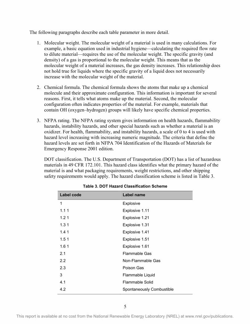
The following paragraphs describe each table parameter in more detail.
1. Molecular weight. The molecular weight of a material is used in many calculations. For example, a basic equation used in industrial hygiene—calculating the required flow rate to dilute material—requires the use of the molecular weight. The specific gravity (and density) of a gas is proportional to the molecular weight. This means that as the molecular weight of a material increases, the gas density increases. This relationship does not hold true for liquids where the specific gravity of a liquid does not necessarily increase with the molecular weight of the material.
2. Chemical formula. The chemical formula shows the atoms that make up a chemical molecule and their approximate configuration. This information is important for several reasons. First, it tells what atoms make up the material. Second, the molecular configuration often indicates properties of the material. For example, materials that contain OH (oxygen–hydrogen) groups will likely have specific chemical properties.
3. NFPA rating. The NFPA rating system gives information on health hazards, flammability hazards, instability hazards, and other special hazards such as whether a material is an oxidizer. For health, flammability, and instability hazards, a scale of 0 to 4 is used with hazard level increasing with increasing numeric magnitude. The criteria that define the hazard levels are set forth in NFPA 704 Identification of the Hazards of Materials for Emergency Response 2001 edition.
DOT classification. The U.S. Department of Transportation (DOT) has a list of hazardous materials in 49 CFR 172.101. This hazard class identifies what the primary hazard of the material is and what packaging requirements, weight restrictions, and other shipping safety requirements would apply. The hazard classification scheme is listed in Table 3.
Table 3. DOT Hazard Classification Scheme
Label code Label name
1 Explosive
1.1 1 Explosive 1.11
1.2 1 Explosive 1.21
1.3 1 Explosive 1.31
1.4 1 Explosive 1.41
1.5 1 Explosive 1.51
1.6 1 Explosive 1.61
2.1 Flammable Gas
2.2 Non-Flammable Gas
2.3 Poison Gas
3 Flammable Liquid
4.1 Flammable Solid
4.2 Spontaneously Combustible

6
This report is available at no cost from the National Renewable Energy Laboratory (NREL) at www.nrel.gov/publications.
4.3 Dangerous When Wet
5.1 Oxidizer
5.2 Organic Peroxide
6.1 (inhalation hazard, Zone A or B)
Poison Inhalation Hazard
6.1 (other than inhalation hazard, Zone A or B)
Poison
7 Radioactive
8 Corrosive
9 Class 9
4. EPA listed hazardous substance. These are substances listed in 40 CFR Table 302.4.
These are materials that are considered hazardous wastes if released into the environment. The column will either be marked as Yes, meaning the material is listed, or No, meaning the material is not listed. If the material is listed the reportable quantity will be shown in pounds. Note that there may be materials not listed that must be reported because they meet the definition of an unlisted waste under 40 CFR 261.2. However, this definition addresses solid materials and would likely not apply to most of the materials covered in this chapter. Also, most of these materials would be regulated as air pollutants and would be subject to air pollution control requirements under 40 CFR.
5. Boiling point. The NFPA 30 Flammable and Combustible Liquids Code defines the boiling point as follows:
The temperature at which the vapor pressure of a liquid equals the surrounding atmospheric pressure.
For purposes of defining the boiling point, atmospheric pressure shall be considered to be 14.7 psia (760 mm Hg). For mixtures that do not have a constant boiling point, the 20 percent evaporated point of a distillation performed in accordance with ASTM D 86, Standard Method of Test for Distillation of Petroleum Products, shall be considered to be the boiling point.
The boiling point is the temperature at which a material will make the phase transition from liquid to gas. This piece of information is critical in understanding what is happening to a material as the storage temperature changes. Many materials are stored under conditions such that the ambient temperature and eventually the material temperature can drop below the boiling point and the material will make a phase transition from a gas to a liquid.
6. Melting point. The melting point is the temperature at which a material makes the transition from the solid phase to the liquid phase. This information is important in determining the physical state of a material. There may be storage conditions that bring a material into the solid phase.

7
This report is available at no cost from the National Renewable Energy Laboratory (NREL) at www.nrel.gov/publications.
7. Vapor pressure. The pressure of a vapor exerted by a pure liquid in equilibrium at a given temperature is referred to as the vapor pressure. The pressure exerted by the vapor is independent as long as there is liquid present. When all of the liquid in a system is vaporized, a further increase in volume will decrease the system pressure in accordance with the ideal gas law.
8. Gas density. The gas density is important data because it is the mass per unit volume at a given temperature and pressure. This is used to determine the pressure required to load a given mass of material into a gas storage container.
9. Gas specific density. This is the density relative to the density of air and will be a strong indicator of whether the gas will rise or sink after a release.
10. Liquid density. This is the mass per unit volume. Unlike gases, the density of liquids is not correlated to molecular weight.
11. Flammable limits in air. The flammable limits are the lower volume limit concentration of a chemical in air that will continue to propagate a flame once initiated. The flame would propagate at any concentration from the lower limit until it reaches an upper limit where the fuel to air ratio is too rich and the flame is quenched. The upper limit may be of concern in a situation where a container with a saturated atmosphere is being vented. During the ventilation process the concentration will move from saturation through the upper flammable limit and into the concentration range where sustained combustion will occur.
12. Net heat of combustion. The heat of combustion is a measure of the amount of energy released during the combustion of a specific chemical. This information is a strong indicator of the impact that a chemical would have if it were involved in a fire.
13. Specific heat. The specific heat of a substance is the amount of heat it absorbs per degree of increased temperature. It is expressed as the thermal energy required to raise a unit mass of the chemical one temperature degree. The constant pressure and constant volume specific heats are given where data are available.
14. Air required for combustion. The air required for combustion is the volume of air required to achieve a stoichiometric mixture that will propagate a flame once initiated.
15. Ignition temperature. The temperature at which a chemical ignites.

8
This report is available at no cost from the National Renewable Energy Laboratory (NREL) at www.nrel.gov/publications.
History of Hydrogen Technologies Hydrogen has been used in industrial applications for more than 100 years (Austin 1984). As a result, the physical properties of hydrogen are well understood for many applications. The effect of hydrogen on a range of materials has been studied and there is extensive literature available on the properties of hydrogen and its effects on materials.
With the emergence of hydrogen fuel cell applications, the following areas are new:
• Storage of high pressure hydrogen in composite materials
• The potential exposure of the general public to high-pressure hydrogen fueling operations
• The location of high-pressure storage containers on vehicles where they are subject to the stresses of vehicle operation
• The widespread use of high-pressure hydrogen storage systems where they could be modified or damaged by individuals unqualified to work on these systems.
Discovery of Hydrogen In 1761, Robert Boyle was able to produce hydrogen from reacting iron filings and dilute acids (Lewis 2001). In 1776, Henry Cavendish identified hydrogen as a unique substance. In 1783, Antoine Lavoisier produced hydrogen (from iron) and named the material hydrogen (Lewis 2001). In 1839 a British scientist, Sir William Robert Grove, developed the first hydrogen-powered fuel cell (Lewis 2001). He was able to produce an electric current flow by constructing a cathode, anode, ceramic membrane, and mixed acid conductive medium. This discovery eventually led to the current hydrogen-powered fuel cell.
Hydrogen has been a known material for more than 200 years. As a result of this relatively early discovery compared to other elements and the widespread industrial use, hydrogen properties are relatively well known. Hydrogen is arguably the most studied element (Rigden 2003). It has the simplest atomic structure, and as a result of that simple structure it has been used to verify fundamental atomic properties.
Hydrogen Use and Applications Hydrogen has many industrial applications, the two most important (based on usage) being ammonia production and hydrogenation of petroleum products to improve combustion characteristics (Ramachandran and Menon 1998). Hydrogen is used in smaller quantities in a variety of industries and applications. Some of these applications are described below.
Glass Manufacturing Larger panes of glass are manufactured using a tin bath upon which molten glass is deposited. The bath creates a flat smooth surface. To prevent oxidation, the tin bath is provided with a positive pressure protective atmosphere consisting of a mixture of nitrogen and hydrogen (Austin 1984).

9
This report is available at no cost from the National Renewable Energy Laboratory (NREL) at www.nrel.gov/publications.
Industrial Heat Transfer Fluid Hydrogen is used as coolant in electric generating equipment. Its relatively low viscosity and high heat capacity make it an effective cooling material.
Hydrogen has a constant pressure heat capacity of 3.41 Btu/(lb R) and a gaseous viscosity of 88.05 micropoise. It has a thermal conductivity of 0.17064 Watts/(m K) (McCarty et al. 1981). Hydrogen can be used in approximately 100% concentration, which means that there is no oxygen present to support combustion.
The absence of oxygen in its cooling gas also means the generator’s high-voltage insulation system will not be damaged by any corona activity in the generator’s stator windings. The localized electric field near a conductor can be sufficiently concentrated to ionize air close to the conductors. This ionized air can create an electrical discharge that has the potential to damage equipment or ignite materials in their flammable concentration range. This is a significant factor in the machine's reliability.
Semiconductor Manufacturing Hydrogen is used in semiconductor manufacturing primarily because of its reducing or oxygen scavenging properties (Wolff 2008). It is also an extremely effective heat transfer fluid, which is an advantageous property in some operations. Hydrogen is used in the following semiconductor manufacturing operations:
• Semiconductor manufacturing
• Semiconductor sintering
• Semiconductor packaging
• Wafer annealing.
Ammonia Production via the Haber-Bosch Process The Haber-Bosch process can produce large amounts of ammonia. Fritz Haber discovered a chemical reaction to produce ammonia and Carl Bosch developed the technology for commercial-scale production of ammonia (Austin 1984). This process is significant because it allows ammonia production on a scale to support large crop production. Ammonia and associated compounds are critical for providing nitrogen to crops.
The Haber process for production of ammonia is shown in the following chemical reaction:
1/2N2 (g) + 3/2H2 (g) ↔ NH3 (g).
The yield for this reaction is increased by using an iron catalyst and increasing the reaction pressure. Hydrogen is a raw feedstock for this reaction. Because of the demand for ammonia, hydrogen is an industrial gas that is produced in large quantities.
Hydrogen in the Petrochemical Industry Hydrogen is used to reduce double bonds to single bonds in hydrocarbons. This reduction process produces hydrocarbon fuels that have better combustion characteristics in internal combustion engines. Hydrogenation of petrochemicals is one of the largest uses of hydrogen.

10
This report is available at no cost from the National Renewable Energy Laboratory (NREL) at www.nrel.gov/publications.
Hydrogen as a Fuel for Fuel Cells As mentioned earlier, hydrogen can be converted into electricity using a fuel cell. These fuel cells can be placed in vehicles to provide electricity for vehicles powered by electric motors or they can be used as stationary sources of electricity. They offer advantages including no combustion emissions and, in the case of stationary fuel cells, reliable power that can be used in emergency situations such as storms or grid outages.
The basic reaction in a hydrogen-powered fuel cell is as follows:
H2 + 1/2O2 → H2O + e- (Larminie and Dicks 2003)
This reaction typically takes place in the presence of a platinum catalyst. The cost of the catalyst is one of the major factors that determine the overall cost of the fuel cell or cells. A single fuel cell does not provide sufficient power for most applications, so the fuel cells are stacked to increase power; hence the term fuel cell stack is used to describe the fuel cells used in both stationary and vehicular applications.
Hydrogen Safety Incidents Pacific Northwest National Laboratory, a DOE national laboratory, administers a database of hydrogen incidents called H2LL, or Hydrogen Lessons Learned.2 This database contains information about incidents that have been voluntarily reported although identifying information has been removed. These lessons learned provide information on safety issues and concerns with hydrogen technologies, but because they are not part of a systematic program of monitoring and reporting on defined processes, frequency information cannot be derived from this database. This database contains approximately 200 entries and is organized using the following classifications:
• Settings
• Equipment
• Damages and injuries
• Probable causes
• Contributing factors.
Many of these entries describe events involving the industrial use of hydrogen or hydrogen usage for applications other than fuel cell electric vehicles or the infrastructure required to support these vehicles. There are very few entries involving the retail use of hydrogen or hydrogen applications that involve exposure to the general public.
The following page shows a screenshot of the database home page.
2 H2LL: Hydrogen Lessons Learned from Incidents and Near-Misses, http://h2tools.org/lessons/.

11
This report is available at no cost from the National Renewable Energy Laboratory (NREL) at www.nrel.gov/publications.

12
This report is available at no cost from the National Renewable Energy Laboratory (NREL) at www.nrel.gov/publications.
Regulations, Codes, and Standards Hydrogen technologies are controlled through codes and standards in a manner similar to other fuels. Figure 1 illustrates the codes and standards hierarchy. The top level of the pyramid consists of building and fire codes that are directly adopted by jurisdictions and are therefore the law in the jurisdiction in which they are adopted. Any code or standard referenced in the body of a building or fire code adopted by a jurisdiction becomes a legally enforceable document in that jurisdiction. These reference documents must be written in an enforceable format to be referenced in building or fire codes. In the topical area of hydrogen technologies these documents comprise the second level of the pyramid. Key documents at this second level include the NFPA 2 Hydrogen Technologies Code and the NFPA 853 Standard for Fuel Cell Energy Systems.
These documents contain references to component standards, which comprise the bottom or third rung of the pyramid. These component standards must also be written in legally enforceable text to be referenced by these second-level codes and standards. Examples of these documents include the CGA S series of documents for pressure relief devices and the American Society of Mechanical Engineers (ASME) B31.12 standard for piping.
Viewed as a package, these documents address all key aspects of system design, construction, operation, and maintenance. Compliance with these requirements should reduce the system risk to a safe level.
The timeline in Figure 1 reflects the development of hydrogen codes and standards over the last eight years.

13
This report is available at no cost from the National Renewable Energy Laboratory (NREL) at www.nrel.gov/publications.
Figure 1. Timeline of codes and standards development and the codes and standards hierarchy
Fire and building codes
Hydrogen-specific codes Example: NFPA 2
Component standards and equipment design codes
Example: CGA G-5.5 or ASME B31.12
2014 2013 2012 2011 2010 2009 2008 2007 2006 2005
California references NFPA 2 in CFC
IFC references NFPA 2
IFC Chapter 22 Hydrogen Fueling
Draft 2nd ed. NFPA 2 developed
NFPA 55 published with clarified setback tables
NFPA 52 authority added to NFPA 2
NFPA 2 1st ed.
NFPA 2 draft
Task Group Bulk Hydrogen
Task Group Bulk Hydrogen
NFPA 2 first committee meeting
NFPA 52 2006 ed. w/ hydrogen fueling
SAE J2601 revision complete
SAE J2579 reissue
CGA H-10 issued
SAE J2719 issued
CSA H series of drafts issued
ASME B31.12 issued
CSA HGV 4
UL2267

14
This report is available at no cost from the National Renewable Energy Laboratory (NREL) at www.nrel.gov/publications.
At the federal level there are regulations, such as 29 CFR 1910 Subpart H Hazardous Materials, that specifically address the storage, use, and handling of hydrogen. Table 4 gives an overview of the regulations, codes, and standards that address hydrogen technologies safety.
Table 4. Overview of Regulations, Codes, and Standards Related to Hydrogen Infrastructure Safety
Federal Regulations OSHA Regulations 29 CFR 1910 Subpart H
Safe storage, use, and handling of hydrogen in the workplace
DOT Regulations 49 CFR 171-179 Safe transport of hydrogen in commerce U.S. National Codes International Building Code (IBC) General construction requirements for building based on
occupancy class International Fire Code (IFC)/NFPA 1 Uniform Fire Code
Requirements for hydrogen fueling stations, flammable gas, and cryogenic fluid storage
International Mechanical Code (IMC) Requirements for ventilation for hydrogen usage in indoor locations
International Fuel Gas Code (IFGC) Requirements for flammable gas piping Hydrogen Technologies Specific Fire Codes and Standards NFPA 2 Hydrogen Technologies Code
Comprehensive code for hydrogen technologies constructed of extract material from documents such as NFPA 55 and 853 and original material
NFPA 55 Compressed Gas and Cryogenic Fluids Code
Comprehensive gas safety code that addresses flammable gases as a class of hazardous materials and also contains hydrogen-specific requirements
NFPA 853 Standard for the Installation of Stationary Fuel Cell Power Systems
Covers installation of all commercial fuel cells including hydrogen PEM fuel cells
Hydrogen Technologies Component, Performance, and Installation Standards ASME B31.3 and B31.12 Piping and Pipelines
Piping design and installation codes that also cover material selection
ASME Boiler and Pressure Vessel (BPV) Code
Addresses design of steel alloy and composite pressure vessels
CGA S series Addresses requirements for pressure relief devices for containers CGA H Series Components and systems UL 2075 Sensors CSA H series of hydrogen component standards
CSA FC1 Stationary fuel cells SAE J2601/SAE J2600 Dispensing and dispenser nozzles The following sections from the OSHA regulations (found in 29 CFR §1910 Subpart H) address the storage, use, and handling of gaseous and liquefied hydrogen. Although these regulations are based on older NFPA documents they are federal regulations. Many jurisdictions will accept compliance with current codes and standards as meeting the OSHA regulations.

15
This report is available at no cost from the National Renewable Energy Laboratory (NREL) at www.nrel.gov/publications.
§ 1910.103 Hydrogen. (a) General—(1) Definitions. As used in this section (i) Gaseous hydrogen system is one in which the hydrogen is delivered, stored and discharged in the gaseous form to consumer’s piping. The system includes stationary or movable containers, pressure regulators, safety relief devices, manifolds, interconnecting piping and controls. The system terminates at the point where hydrogen at service pressure first enters the consumer’s distribution piping.
(ii) Approved—Means, unless otherwise indicated, listed or approved by a nationally recognized testing laboratory. Refer to § 1910.7 for definition of nationally recognized testing laboratory.
(iii) Listed—See “approved”.
(iv) ASME—American Society of Mechanical Engineers.
(v) DOT Specifications—Regulations of the Department of Transportation published in 49 CFR Chapter I. (vi) DOT regulations—See § 1910.103 (a)(1)(v).
(2) Scope—(i) Gaseous hydrogen systems. (a) Paragraph (b) of this section applies to the installation of gaseous hydrogen systems on consumer premises where the hydrogen supply to the consumer premises originates outside the consumer premises and is delivered by mobile equipment.
(b) Paragraph (b) of this section does not apply to gaseous hydrogen systems having a total hydrogen content of less than 400 cubic feet, nor to hydrogen manufacturing plants or other establishments operated by the hydrogen supplier or his agent for the purpose of storing hydrogen and refilling portable containers, trailers, mobile supply trucks, or tank cars.
(ii) Liquefied hydrogen systems. (a) Paragraph (c) of this section applies to the installation of liquefied hydrogen systems on consumer premises.
(b) Paragraph (c) of this section does not apply to liquefied hydrogen portable containers of less than 150 liters (39.63 gallons) capacity; nor to liquefied hydrogen manufacturing plants or other establishments operated by the hydrogen supplier or his agent for the sole purpose of storing liquefied hydrogen and refilling portable containers, trailers, mobile supply trucks, or tank cars.
(b) Gaseous hydrogen systems—(1) Design—(i) Containers. (a) Hydrogen containers shall comply with one of the following:
(1) Designed, constructed, and tested in accordance with appropriate requirements of ASME Boiler and Pressure Vessel Code, section VIII—Unfired Pressure Vessels—1968, which is incorporated by reference as specified in § 1910.6.
(2) Designed, constructed, tested and maintained in accordance with U.S. Department of Transportation Specifications and Regulations.
(b) Permanently installed containers shall be provided with substantial noncombustible supports on firm noncombustible foundations.

16
This report is available at no cost from the National Renewable Energy Laboratory (NREL) at www.nrel.gov/publications.
(c) Each portable container shall be legibly marked with the name “Hydrogen” in accordance with the marking requirements set forth in § 1910.253(b)(1)(ii). Each manifolded hydrogen supply unit shall be legibly marked with the name “Hydrogen” or a legend such as “This unit contains hydrogen.”
(ii) Safety relief devices. (a) Hydrogen containers shall be equipped with safety relief devices as required by the ASME Boiler and Pressure Vessel Code, section VIII Unfired Pressure Vessels, 1968 or the DOT Specifications and Regulations under which the container is fabricated.
(b) Safety relief devices shall be arranged to discharge upward and unobstructed to the open air in such a manner as to prevent any impingement of escaping gas upon the container, adjacent structure or personnel. This requirement does not apply to DOT Specification containers having an internal volume of 2 cubic feet or less.
(c) Safety relief devices or vent piping shall be designed or located so that moisture cannot collect and freeze in a manner which would interfere with proper operation of the device.
(iii) Piping, tubing, and fittings. (a) Piping, tubing, and fittings shall be suitable for hydrogen service and for the pressures and temperatures involved. Cast iron pipe and fittings shall not be used.
(b) Piping and tubing shall conform to section 2—“Industrial Gas and Air Piping”—Code for Pressure Piping, ANSI B31.1–1967 with addenda B31.1–1969, which is incorporated by reference as specified in § 1910.6.
(c) Joints in piping and tubing may be made by welding or brazing or by use of flanged, threaded, socket, or compression fittings. Gaskets and thread sealants shall be suitable for hydrogen service.
(iv) Equipment assembly. (a) Valves, gauges, regulators, and other accessories shall be suitable for hydrogen service.
(b) Installation of hydrogen systems shall be supervised by personnel familiar with proper practices with reference to their construction and use.
(c) Storage containers, piping, valves, regulating equipment, and other accessories shall be readily accessible, and shall be protected against physical damage and against tampering.
(d) Cabinets or housings containing hydrogen control or operating equipment shall be adequately ventilated.
(e) Each mobile hydrogen supply unit used as part of a hydrogen system shall be adequately secured to prevent movement.
(f) Mobile hydrogen supply units shall be electrically bonded to the system before discharging hydrogen.
(v) Marking. The hydrogen storage location shall be permanently placarded as follows: “HYDROGEN—FLAMMABLE GAS—NO SMOKING—NO OPEN FLAMES,” or equivalent.
17
This report is available at no cost from the National Renewable Energy Laboratory (NREL) at www.nrel.gov/publications.
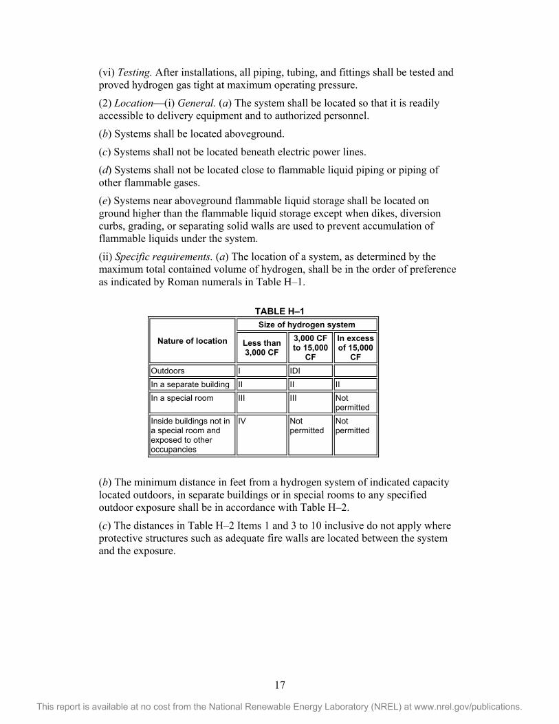
(vi) Testing. After installations, all piping, tubing, and fittings shall be tested and proved hydrogen gas tight at maximum operating pressure.
(2) Location—(i) General. (a) The system shall be located so that it is readily accessible to delivery equipment and to authorized personnel.
(b) Systems shall be located aboveground.
(c) Systems shall not be located beneath electric power lines.
(d) Systems shall not be located close to flammable liquid piping or piping of other flammable gases.
(e) Systems near aboveground flammable liquid storage shall be located on ground higher than the flammable liquid storage except when dikes, diversion curbs, grading, or separating solid walls are used to prevent accumulation of flammable liquids under the system.
(ii) Specific requirements. (a) The location of a system, as determined by the maximum total contained volume of hydrogen, shall be in the order of preference as indicated by Roman numerals in Table H–1.
TABLE H–1
Nature of location
Size of hydrogen system
Less than 3,000 CF
3,000 CF to 15,000
CF
In excess of 15,000
CF Outdoors I IDI In a separate building II II II In a special room III III Not
permitted Inside buildings not in a special room and exposed to other occupancies
IV Not permitted
Not permitted
(b) The minimum distance in feet from a hydrogen system of indicated capacity located outdoors, in separate buildings or in special rooms to any specified outdoor exposure shall be in accordance with Table H–2.
(c) The distances in Table H–2 Items 1 and 3 to 10 inclusive do not apply where protective structures such as adequate fire walls are located between the system and the exposure.

18
This report is available at no cost from the National Renewable Energy Laboratory (NREL) at www.nrel.gov/publications.
TABLE H–2
Type of outdoor exposure
Size of hydrogen system
Less than 3,000 CF
3,000 CF to 15,000
CF
In excess of 15,000
CF 1. Building or structure Wood frame construction 1
Heavy timber, noncombustible or ordinary construction 1 Fire-resistive construction 1
10 0
0
25 10
0
50 2 25
0
2. Wall openings Not above any part of a system Above any part of a system
10 25
10 25
10 25
3. Flammable liquids above ground 0 to 1,000 gallons In excess of 1,000 gallons
10 25
25 50
25 50
4. Flammable liquids below ground—0 to 1,000 gallons
Tank Vent or fill opening of tank
10 25
10 25
10 25
5. Flammable liquids below ground—in excess of 1,000 gallons
Tank Vent or fill opening of tank
20 25
20 25
20 25
6. Flammable gas storage, either high pressure or low pressure
0 to 15,000 CF capacity In excess of 15,000 CF capacity
10 25
25 50
25 50
7. Oxygen storage 12,000 CF or less 4 More than 12,000 CF 5
-- --
-- --
-- --
8. Fast burning solids such as ordinary lumber, excelsior or paper 50 50 50 9. Slow burning solids such as heavy timber or coal 25 25 25 10. Open flames and other sources of ignition 25 25 25 11. Air compressor intakes or inlets to ventilating or air-conditioning equipment 50 50 50 12. Concentration of people 3 25 50 50 1 Refer to NFPA No. 220 Standard Types of Building Construction for definitions of various types of construction. (1969 Ed.) 2 But not less than one-half the height of adjacent side wall of the structure. 3 In congested areas such as offices, lunchrooms, locker rooms, time-clock areas. 4 Refer to NFPA No 51, gas systems for welding and cutting (1969). 5 Refer to NFPA No 566, bulk oxygen systems at consumer sites (1969).
(d) Hydrogen systems of less than 3,000 CF when located inside buildings and exposed to other occupancies shall be situated in the building so that the system will be as follows:
(1) In an adequately ventilated area as in paragraph (b)(3)(ii)(b) of this section.
(2) Twenty feet from stored flammable materials or oxidizing gases.
(3) Twenty-five feet from open flames, ordinary electrical equipment or other sources of ignition.
(4) Twenty-five feet from concentrations of people.
(5) Fifty feet from intakes of ventilation or air-conditioning equipment and air compressors.
(6) Fifty feet from other flammable gas storage.
(7) Protected against damage or injury due to falling objects or working activity in the area.

19
This report is available at no cost from the National Renewable Energy Laboratory (NREL) at www.nrel.gov/publications.
(8) More than one system of 3,000 CF or less may be installed in the same room, provided the systems are separated by at least 50 feet. Each such system shall meet all of the requirements of this paragraph.
(3) Design consideration at specific locations—(i) Outdoor locations. (a) Where protective walls or roofs are provided, they shall be constructed of noncombustible materials.
(b) Where the enclosing sides adjoin each other, the area shall be properly ventilated.
(c) Electrical equipment within 15 feet shall be in accordance with subpart S of this part.
(ii) Separate buildings. (a) Separate buildings shall be built of at least noncombustible construction. Windows and doors shall be located so as to be readily accessible in case of emergency. Windows shall be of glass or plastic in metal frames.
(b) Adequate ventilation to the outdoors shall be provided. Inlet openings shall be located near the floor in exterior walls only. Outlet openings shall be located at the high point of the room in exterior walls or roof. Inlet and outlet openings shall each have minimum total area of one (1) square foot per 1,000 cubic feet of room volume. Discharge from outlet openings shall be directed or conducted to a safe location.
(c) Explosion venting shall be provided in exterior walls or roof only. The venting area shall be equal to not less than 1 square foot per 30 cubic feet of room volume and may consist of any one or any combination of the following: Walls of light, noncombustible material, preferably single thickness, single strength glass; lightly fastened hatch covers; lightly fastened swinging doors in exterior walls opening outward; lightly fastened walls or roof designed to relieve at a maximum pressure of 25 pounds per square foot.
(d) There shall be no sources of ignition from open flames, electrical equipment, or heating equipment.
(e) Electrical equipment shall be in accordance with subpart S of this part for Class I, Division 2 locations.
(f) Heating, if provided, shall be by steam, hot water, or other indirect means.
(iii) Special rooms. (a) Floor, walls, and ceiling shall have a fire-resistance rating of at least 2 hours. Walls or partitions shall be continuous from floor to ceiling and shall be securely anchored. At least one wall shall be an exterior wall. Openings to other parts of the building shall not be permitted. Windows and doors shall be in exterior walls and shall be located so as to be readily accessible in case of emergency. Windows shall be of glass or plastic in metal frames.
(b) Ventilation shall be as provided in paragraph (b)(3)(ii)(b) of this section.
(c) Explosion venting shall be as provided in paragraph (b)(3)(ii)(c) of this section.

20
This report is available at no cost from the National Renewable Energy Laboratory (NREL) at www.nrel.gov/publications.
(d) There shall be no sources of ignition from open flames, electrical equipment, or heating equipment.
(e) Electric equipment shall be in accordance with the requirements of subpart S of this part for Class I, Division 2 locations.
(f) Heating, if provided, shall be by steam, hot water, or indirect means.
(4) Operating instructions. For installations which require any operation of equipment by the user, legible instructions shall be maintained at operating locations.
(5) Maintenance. The equipment and functioning of each charged gaseous hydrogen system shall be maintained in a safe operating condition in accordance with the requirements of this section. The area within 15 feet of any hydrogen container shall be kept free of dry vegetation and combustible material.
(c) Liquefied hydrogen systems—(1) Design—(i) Containers. (a) Hydrogen containers shall comply with the following: Storage containers shall be designed, constructed, and tested in accordance with appropriate requirements of the ASME Boiler and Pressure Vessel Code, section VIII—Unfired Pressure Vessels (1968) or applicable provisions of API Standard 620, Recommended Rules for Design and Construction of Large, Welded, Low-Pressure Storage Tanks, Second Edition (June 1963) and appendix R (April 1965), which is incorporated by reference as specified in § 1910.6.
(b) Portable containers shall be designed, constructed and tested in accordance with DOT Specifications and Regulations.
(ii) Supports. Permanently installed containers shall be provided with substantial noncombustible supports securely anchored on firm noncombustible foundations. Steel supports in excess of 18 inches in height shall be protected with a protective coating having a 2-hour fire-resistance rating.
(iii) Marking. Each container shall be legibly marked to indicate “LIQUEFIED HYDROGEN—FLAMMABLE GAS.”
(iv) Safety relief devices. (a)(1) Stationary liquefied hydrogen containers shall be equipped with safety relief devices sized in accordance with CGA Pamphlet S–1, part 3, Safety Relief Device Standards for Compressed Gas Storage Containers, which is incorporated by reference as specified in § 1910.6.
(2) Portable liquefied hydrogen containers complying with the U.S. Department of Transportation Regulations shall be equipped with safety relief devices as required in the U.S. Department of Transportation Specifications and Regulations. Safety relief devices shall be sized in accordance with the requirements of CGA Pamphlet S–1, Safety Relief Device Standards, part 1, Compressed Gas Cylinders and part 2, Cargo and Portable Tank Containers.
(b) Safety relief devices shall be arranged to discharge unobstructed to the outdoors and in such a manner as to prevent impingement of escaping liquid or gas upon the container, adjacent structures or personnel. See paragraph (c)(2)(i)(f) of this section for venting of safety relief devices in special locations.

21
This report is available at no cost from the National Renewable Energy Laboratory (NREL) at www.nrel.gov/publications.
(c) Safety relief devices or vent piping shall be designed or located so that moisture cannot collect and freeze in a manner which would interfere with proper operation of the device.
(d) Safety relief devices shall be provided in piping wherever liquefied hydrogen could be trapped between closures.
(v) Piping, tubing, and fittings. (a) Piping, tubing, and fittings and gasket and thread sealants shall be suitable for hydrogen service at the pressures and temperatures involved. Consideration shall be given to the thermal expansion and contraction of piping systems when exposed to temperature fluctuations of ambient to liquefied hydrogen temperatures.
(b) Gaseous hydrogen piping and tubing (above –20 °F.) shall conform to the applicable sections of Pressure Piping section 2—Industrial Gas and Air Piping, ANSI B31.1–1967 with addenda B31.1–1969. Design of liquefied hydrogen or cold (–20 °F. or below) gas piping shall use Petroleum Refinery Piping ANSI B31.3–1966 or Refrigeration Piping ANSI B31.5–1966 with addenda B31.5a–1968 as a guide, which are incorporated by reference as specified in § 1910.6.
(c) Joints in piping and tubing shall preferably be made by welding or brazing; flanged, threaded, socket, or suitable compression fittings may be used.
(d) Means shall be provided to minimize exposure of personnel to piping operating at low temperatures and to prevent air condensate from contacting piping, structural members, and surfaces not suitable for cryogenic temperatures. Only those insulating materials which are rated nonburning in accordance with ASTM Procedures D1692–68, which is incorporated by reference as specified in § 1910.6, may be used. Other protective means may be used to protect personnel. The insulation shall be designed to have a vapor-tight seal in the outer covering to prevent the condensation of air and subsequent oxygen enrichment within the insulation. The insulation material and outside shield shall also be of adequate design to prevent attrition of the insulation due to normal operating conditions.
(e) Uninsulated piping and equipment which operate at liquefied-hydrogen temperature shall not be installed above asphalt surfaces or other combustible materials in order to prevent contact of liquid air with such materials. Drip pans may be installed under uninsulated piping and equipment to retain and vaporize condensed liquid air.
(vi) Equipment assembly. (a) Valves, gauges, regulators, and other accessories shall be suitable for liquefied hydrogen service and for the pressures and temperatures involved.
(b) Installation of liquefied hydrogen systems shall be supervised by personnel familiar with proper practices and with reference to their construction and use.
(c) Storage containers, piping, valves, regulating equipment, and other accessories shall be readily accessible and shall be protected against physical damage and against tampering. A shutoff valve shall be located in liquid product withdrawal lines as close to the container as practical. On containers of over 2,000 gallons capacity, this shutoff valve shall be of the remote control type with no
22
This report is available at no cost from the National Renewable Energy Laboratory (NREL) at www.nrel.gov/publications.
connections, flanges, or other appurtenances (other than a welded manual shutoff valve) allowed in the piping between the shutoff valve and its connection to the inner container.
(d) Cabinets or housings containing hydrogen control equipment shall be ventilated to prevent any accumulation of hydrogen gas.
(vii) Testing. (a) After installation, all field-erected piping shall be tested and proved hydrogen gas-tight at operating pressure and temperature.
(b) Containers if out of service in excess of 1 year shall be inspected and tested as outlined in (a) of this subdivision. The safety relief devices shall be checked to determine if they are operable and properly set.
(viii) Liquefied hydrogen vaporizers. (a) The vaporizer shall be anchored and its connecting piping shall be sufficiently flexible to provide for the effect of expansion and contraction due to temperature changes.
(b) The vaporizer and its piping shall be adequately protected on the hydrogen and heating media sections with safety relief devices.
(c) Heat used in a liquefied hydrogen vaporizer shall be indirectly supplied utilizing media such as air, steam, water, or water solutions.
(d) A low temperature shutoff switch shall be provided in the vaporizer discharge piping to prevent flow of liquefied hydrogen in the event of the loss of the heat source.
(ix) Electrical systems. (a) Electrical wiring and equipment located within 3feet of a point where connections are regularly made and disconnected, shall be in accordance with subpart S of this part, for Class I, Group B, Division 1 locations.
(b) Except as provided in (a) of this subdivision, electrical wiring, and equipment located within 25 feet of a point where connections are regularly made and disconnected or within 25 feet of a liquid hydrogen storage container, shall be in accordance with subpart S of this part, for Class I, Group B, Division 2 locations. When equipment approved for class I, group B atmospheres is not commercially available, the equipment may be—
(1) Purged or ventilated in accordance with NFPA No. 496–1967, Standard for Purged Enclosures for Electrical Equipment in Hazardous Locations,
(2) Intrinsically safe, or
(3) Approved for Class I, Group C atmospheres. This requirement does not apply to electrical equipment which is installed on mobile supply trucks or tank cars from which the storage container is filled.
(x) Bonding and grounding. The liquefied hydrogen container and associated piping shall be electrically bonded and grounded.
(2) Location of liquefied hydrogen storage—(i) General requirements. (a) The storage containers shall be located so that they are readily accessible to mobile supply equipment at ground level and to authorized personnel.

23
This report is available at no cost from the National Renewable Energy Laboratory (NREL) at www.nrel.gov/publications.
(b) The containers shall not be exposed by electric power lines, flammable liquid lines, flammable gas lines, or lines carrying oxidizing materials.
(c) When locating liquefied hydrogen storage containers near above-ground flammable liquid storage or liquid oxygen storage, it is advisable to locate the liquefied hydrogen container on ground higher than flammable liquid storage or liquid oxygen storage.
(d) Where it is necessary to locate the liquefied hydrogen container on ground that is level with or lower than adjacent flammable liquid storage or liquid oxygen storage, suitable protective means shall be taken (such as by diking, diversion curbs, grading), with respect to the adjacent flammable liquid storage or liquid oxygen storage, to prevent accumulation of liquids within 50 feet of the liquefied hydrogen container.
(e) Storage sites shall be fenced and posted to prevent entrance by unauthorized personnel. Sites shall also be placarded as follows: “Liquefied Hydrogen—Flammable Gas—No Smoking—No Open Flames.”
(f) If liquefied hydrogen is located in (as specified in Table H–3) a separate building, in a special room, or inside buildings when not in a special room and exposed to other occupancies, containers shall have the safety relief devices vented unobstructed to the outdoors at a minimum elevation of 25 feet above grade to a safe location as required in paragraph (c)(1)(iv)(b) of this section.
(ii) Specific requirements. (a) The location of liquefied hydrogen storage, as determined by the maximum total quantity of liquefied hydrogen, shall be in the order of preference as indicated by Roman numerals in the following Table H–3.
TABLE H–3—MAXIMUM TOTAL QUANTITY OF LIQUEFIED HYDROGEN STORAGE PERMITTED
Nature of location Size of hydrogen storage (capacity in gallons)
39.63 (150 liters) to 50 51 to 300 301 to 600 In excess of 600
Outdoors I I I I In a separate building II II II Not permitted In a special room III III Not permitted Do. Inside buildings not in a special room and exposed to other occupancies
IV Not permitted Do. Do.
NOTE: This table does not apply to the storage in dewars of the type generally used in laboratories for experimental purposes.
(b) The minimum distance in feet from liquefied hydrogen systems of indicated storage capacity located outdoors, in a separate building, or in a special room to any specified exposure shall be in accordance with Table H–4.

24
This report is available at no cost from the National Renewable Energy Laboratory (NREL) at www.nrel.gov/publications.
TABLE H–4—MINIMUM DISTANCE (FEET) FROM LIQUEFIED HYDROGEN SYSTEMS TO EXPOSURE 1,2
Type of Exposure
Liquefied hydrogen storage (capacity in gallons)
39.63 (150 liters) to 3,500
3,501 to 15,000
15,001 to 30,000
1. Fire-resistive building and fire walls 3 5 5 5 2. Noncombustible building 3 25 50 75 3. Other buildings 3 50 75 100 4. Wall openings, air-compressor intakes, inlets for air-conditioning or ventilating equipment
75 75 75
5. Flammable liquids (above ground and vent or fill openings if below ground) (see 513 and 514)
50 75 100
6. Between stationary liquefied hydrogen containers 5 5 5 7. Flammable gas storage 50 75 100 8. Liquid oxygen storage and other oxidizers (see 513 and 514) 100 100 100 9. Combustible solids 50 75 100 10. Open flames, smoking and welding 50 50 50 11. Concentrations of people 75 75 75 1 The distance in Nos. 2, 3, 5, 7, 9, and 12 in Table H-4 may be reduced where protective structures, such as firewalls equal to height of top of the container, to safeguard the liquefied hydrogen storage system, are located between the liquefied hydrogen storage installation and the exposure. 2 Where protective structures are provided, ventilation and confinement of product should be considered. The 5-foot distance in Nos. 1 and 6 facilitates maintenance and enhances ventilation. 3 Refer to Standard Types of Building Construction, NFPA No. 220-1969 for definitions of various types of construction. In congested areas such as offices, lunchrooms, locker rooms, time-clock areas.
(iii) Handling of liquefied hydrogen inside buildings other than separate buildings and special rooms. Portable liquefied hydrogen containers of 50 gallons or less capacity as permitted in Table H–3 and in compliance with subdivision (i)(f) of this subparagraph when housed inside buildings not located in a special room and exposed to other occupancies shall comply with the following minimum requirements:
(a) Be located 20 feet from flammable liquids and readily combustible materials such as excelsior or paper.
(b) Be located 25 feet from ordinary electrical equipment and other sources of ignition including process or analytical equipment.
(c) Be located 25 feet from concentrations of people.
(d) Be located 50 feet from intakes of ventilation and air-conditioning equipment or intakes of compressors.
(e) Be located 50 feet from storage of other flammable-gases or storage of oxidizing gases.
(f) Containers shall be protected against damage or injury due to falling objects or work activity in the area.
(g) Containers shall be firmly secured and stored in an upright position.

25
This report is available at no cost from the National Renewable Energy Laboratory (NREL) at www.nrel.gov/publications.
(h) Welding or cutting operations, and smoking shall be prohibited while hydrogen is in the room.
(i) The area shall be adequately ventilated. Safety relief devices on the containers shall be vented directly outdoors or to a suitable hood. See paragraphs (c)(1)(iv)(b) and (c)(2)(i)(f) of this section.
(3) Design considerations at specific locations—(i) Outdoor locations. (a) Outdoor location shall mean outside of any building or structure, and includes locations under a weather shelter or canopy provided such locations are not enclosed by more than two walls set at right angles and are provided with vent-space between the walls and vented roof or canopy.
(b) Roadways and yard surfaces located below liquefied hydrogen piping, from which liquid air may drip, shall be constructed of noncombustible materials.
(c) If protective walls are provided, they shall be constructed of noncombustible materials and in accordance with the provisions of paragraph (c)(3)(i)(a) of this section.
(d) Electrical wiring and equipment shall comply with paragraph (c)(1)(ix) (a) and (b) of this section.
(e) Adequate lighting shall be provided for nighttime transfer operation.
(ii) Separate buildings. (a) Separate buildings shall be of light noncombustible construction on a substantial frame. Walls and roofs shall be lightly fastened and designed to relieve at a maximum internal pressure of 25 pounds per square foot. Windows shall be of shatterproof glass or plastic in metal frames. Doors shall be located in such a manner that they will be readily accessible to personnel in an emergency.
(b) Adequate ventilation to the outdoors shall be provided. Inlet openings shall be located near the floor level in exterior walls only. Outlet openings shall be located at the high point of the room in exterior walls or roof. Both the inlet and outlet vent openings shall have a minimum total area of 1 square foot per 1,000 cubic feet of room volume. Discharge from outlet openings shall be directed or conducted to a safe location.
(c) There shall be no sources of ignition.
(d) Electrical wiring and equipment shall comply with paragraphs (c)(1)(ix) (a) and (b) of this section except that the provisions of paragraph (c)(1)(ix)(b) of this section shall apply to all electrical wiring and equipment in the separate building.
(e) Heating, if provided, shall be by steam, hot water, or other indirect means.
(iii) Special rooms. (a) Floors, walls, and ceilings shall have a fire resistance rating of at least 2 hours. Walls or partitions shall be continuous from floor to ceiling and shall be securely anchored. At least one wall shall be an exterior wall. Openings to other parts of the building shall not be permitted. Windows and doors shall be in exterior walls and doors shall be located in such a manner that they

26
This report is available at no cost from the National Renewable Energy Laboratory (NREL) at www.nrel.gov/publications.
will be accessible in an emergency. Windows shall be of shatterproof glass or plastic in metal frames.
(b) Ventilation shall be as provided in paragraph (c)(3)(ii)(b) of this section.
(c) Explosion venting shall be provided in exterior walls or roof only. The venting area shall be equal to not less than 1 square foot per 30 cubic feet of room volume and may consist of any one or any combination of the following: Walls of light noncombustible material; lightly fastened hatch covers; lightly fastened swinging doors opening outward in exterior walls; lightly fastened walls or roofs designed to relieve at a maximum pressure of 25 pounds per square foot.
(d) There shall be no sources of ignition.
(e) Electrical wiring and equipment shall comply with paragraph (c)(1)(ix) (a) and (b) of this section except that the provision of paragraph (c)(1)(ix)(b) of this section shall apply to all electrical wiring and equipment in the special room.
(f) Heating, if provided, shall be steam, hot water, or by other indirect means.
(4) Operating instructions—(i) Written instructions. For installations which require any operation of equipment by the user, legible instructions shall be maintained at operating locations.
(ii) Attendant. A qualified person shall be in attendance at all times while the mobile hydrogen supply unit is being unloaded.
(iii) Security. Each mobile liquefied hydrogen supply unit used as part of a hydrogen system shall be adequately secured to prevent movement.
(iv) Grounding. The mobile liquefied hydrogen supply unit shall be grounded for static electricity.
(5) Maintenance. The equipment and functioning of each charged liquefied hydrogen system shall be maintained in a safe operating condition in accordance with the requirements of this section. Weeds or similar combustibles shall not be permitted within 25 feet of any liquefied hydrogen equipment.
[39 FR 23502, June 27, 1974, as amended at 43 FR 49746, Oct. 24, 1978; 53 FR 12121, Apr. 12, 1988; 55 FR 32015, Aug. 6, 1990; 58 FR 35309, June 30, 1993; 61 FR 9236, 9237, Mar. 7, 1996; 69 FR 31881, June 8, 2004; 72 FR 71069, Dec. 14, 2007]

27
This report is available at no cost from the National Renewable Energy Laboratory (NREL) at www.nrel.gov/publications.
Material Selection for Hydrogen Technologies Hydrogen can damage storage, piping, and appurtenance materials through processes that are partially a function of the relatively small size of the hydrogen molecule. There is an extensive literature that covers the destructive capabilities of hydrogen and its effects on materials. Volume 13a of the American Society of Materials (ASM) handbook series, “Corrosion: Fundamentals, Testing, and Protection,” has a chapter devoted to hydrogen (Cramer and Covino 2003).
This guide is primarily focused on assisting with deployment of emerging hydrogen technologies, so there will be no literature review. Instead there is a brief discussion of the resources available to use when selecting materials for use in hydrogen fueling systems and storage systems for stationary fuel cells. Several of these resources are found in codes and standards documents. The ASME documents provide key requirements for deploying hydrogen technologies.
The ASME B31.12 Hydrogen Pipelines and Piping code specifies materials that can be used for hydrogen applications. This material selection information is found in Chapter GR-2 of the code.
The ASME BPV code provides extensive information on material selection and testing for hydrogen usage. This material covers the use of both metals and composite materials for container construction. This topic is initially covered in Section A, Part UG. The ASME BPV Section XIII also contains Code Case 2579-3 Composite Reinforced Pressure Vessels for Gaseous H2 Service.
Both of these ASME documents are or will be referenced in building and fire codes and are therefore likely enforceable requirements in most jurisdictions in the United States.
The ASME B31.12 documents give procedures for calculating pipe diameters based on operation parameters. Chapter GR-2—Materials addresses the following topics:
• Materials and specification
• Temperature limitations
• Impact testing methods and acceptance criteria
• Fluid service requirements for materials
• Deterioration of materials in service
• Joining and auxiliary materials.
The Canadian Standards Association (CSA) document CSA CHMC-1 addresses material testing for hydrogen applications. ANSI/CSA CHMC 1—2014 Test Method for Evaluating Material Compatibility in Compressed Hydrogen Applications—Phase I—Metals has the following scope:
This standard provides uniform test methods for evaluating material compatibility with compressed hydrogen applications. The results of these tests are intended to provide a basic comparison of materials performance in applications utilizing compressed hydrogen. This standard is not intended to replace the targeted testing

28
This report is available at no cost from the National Renewable Energy Laboratory (NREL) at www.nrel.gov/publications.
which may be necessary to qualify the design of a component manufactured for use in hydrogen applications.
The American Society of Testing Materials (ASTM) has published a book on hydrogen embrittlement entitled “Hydrogen Embrittlement: Prevention and Control ASTM STP 692.” This book covers the different test methods used to evaluate metals susceptibility to hydrogen attack.
Sandia National Laboratories has published a guide for selecting materials for hydrogen technology applications. This document is a compendium of papers detailing the material selection criteria for different types of materials that could potentially be used for hydrogen applications. It can be found at the following website: http://www.sandia.gov/matlsTechRef/.
29
This report is available at no cost from the National Renewable Energy Laboratory (NREL) at www.nrel.gov/publications.
Component Selection for Hydrogen Technologies Hydrogen component selection and material selection are closely related topics. Components must be sized to handle the design loads and materials must be selected that can perform safely and reliably over the life of the component. Hydrogen has been used in industrial processes so there is information on components that will perform in hydrogen environments that can be used in developing hydrogen applications such as hydrogen fuel cell vehicles and stationary hydrogen-powered fuel cells. There are several codes and standards that set component design or performance requirements. The following are some of the documents that address component design:
• ASME B31.12 Hydrogen Pipelines and Piping for pipe sizing procedures
• CGA S-1.1 through 1.3 for pressure relief devices for hydrogen storage containers
• ASME BPV Section XIII for hydrogen containers
• DOT 49 CFR 171-179 for hydrogen cylinders
• CGA H.3 for hydrogen vent systems
• UL 2075 for hydrogen sensors
• NIST Handbook 44 for hydrogen meters
• CSA HGV 4.2 for hydrogen hoses
• CSA HGV 4.2 for hydrogen nozzles.
Hydrogen storage systems typically include the following components:
• Valves
• Pressure relief devices
• Pumps/compressors
• Sensors/detection systems
• Storage containers
• Vent stacks.
Hydrogen dispensing systems typically include the following additional components:
• Meters
• Nozzles
• Dispensing hoses
• Emergency shutoffs or “E stops”
• Sensors for detecting hydrogen leaks.
Component selection consists of sizing and system design. This section cannot address system design because that topic is too complex for a guidance document. Generally, hydrogen systems
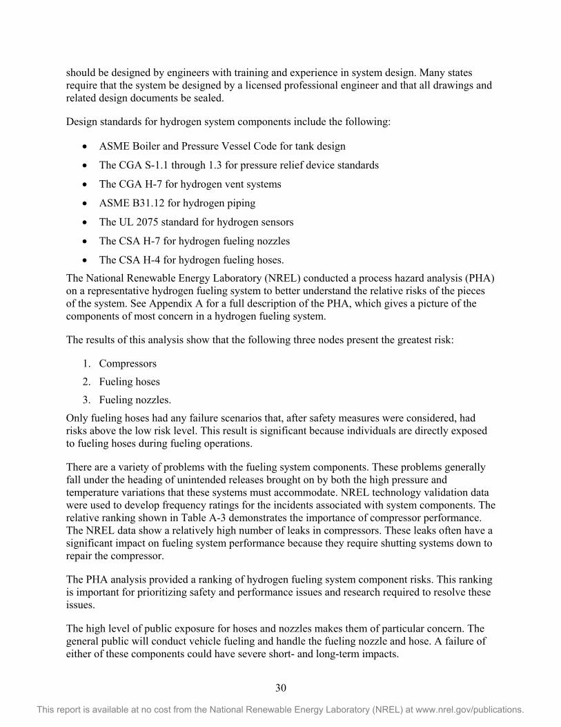
30
This report is available at no cost from the National Renewable Energy Laboratory (NREL) at www.nrel.gov/publications.
should be designed by engineers with training and experience in system design. Many states require that the system be designed by a licensed professional engineer and that all drawings and related design documents be sealed.
Design standards for hydrogen system components include the following:
• ASME Boiler and Pressure Vessel Code for tank design
• The CGA S-1.1 through 1.3 for pressure relief device standards
• The CGA H-7 for hydrogen vent systems
• ASME B31.12 for hydrogen piping
• The UL 2075 standard for hydrogen sensors
• The CSA H-7 for hydrogen fueling nozzles
• The CSA H-4 for hydrogen fueling hoses.
The National Renewable Energy Laboratory (NREL) conducted a process hazard analysis (PHA) on a representative hydrogen fueling system to better understand the relative risks of the pieces of the system. See Appendix A for a full description of the PHA, which gives a picture of the components of most concern in a hydrogen fueling system.
The results of this analysis show that the following three nodes present the greatest risk:
1. Compressors
2. Fueling hoses
3. Fueling nozzles.
Only fueling hoses had any failure scenarios that, after safety measures were considered, had risks above the low risk level. This result is significant because individuals are directly exposed to fueling hoses during fueling operations.
There are a variety of problems with the fueling system components. These problems generally fall under the heading of unintended releases brought on by both the high pressure and temperature variations that these systems must accommodate. NREL technology validation data were used to develop frequency ratings for the incidents associated with system components. The relative ranking shown in Table A-3 demonstrates the importance of compressor performance. The NREL data show a relatively high number of leaks in compressors. These leaks often have a significant impact on fueling system performance because they require shutting systems down to repair the compressor.
The PHA analysis provided a ranking of hydrogen fueling system component risks. This ranking is important for prioritizing safety and performance issues and research required to resolve these issues.
The high level of public exposure for hoses and nozzles makes them of particular concern. The general public will conduct vehicle fueling and handle the fueling nozzle and hose. A failure of either of these components could have severe short- and long-term impacts.

31
This report is available at no cost from the National Renewable Energy Laboratory (NREL) at www.nrel.gov/publications.
The Permitting Process The permitting process is actually several processes typically involving multiple permits and agencies. The processes are in place to protect public safety, public health, and the environment. An example of the permits, agencies, and purposes for these multiple processes is shown in Table 5.
The permitting processes can be broken down into the following seven stages that help define the overall process and the timeline for completing all of the required components:
1. Preliminary project scoping
2. Station design
3. Approval process
4. Station/dispenser construction
5. Station/dispenser startup
6. Station/dispenser operation
7. Station/dispenser maintenance.
The required permits address all of these phases, but the permitting structure does not correlate on a one-to-one basis with the chronological steps required to build and operate a dispensing station. Table 5 and Table 6 list elements of the permitting and approval processes. The difference between these tables is that there are regulatory agencies that typically issue a permit after the applicant has shown compliance with requirements and agencies that approve of an applicant’s submission without issuing a permit.
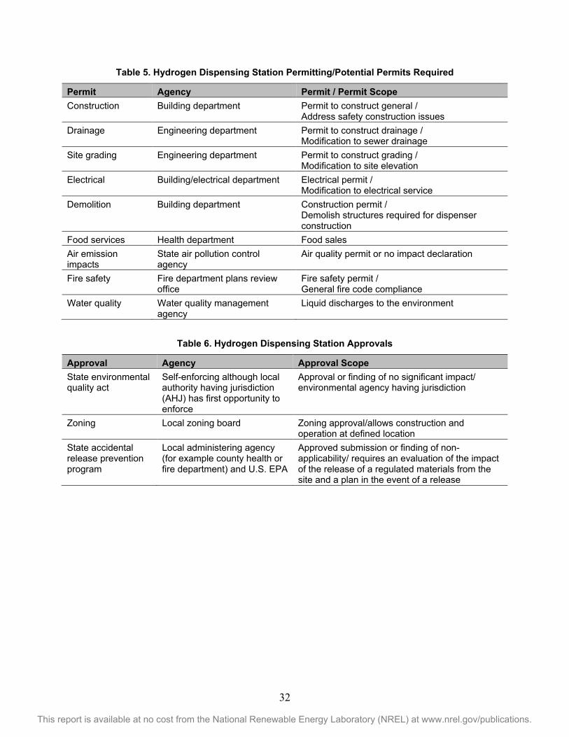
32
This report is available at no cost from the National Renewable Energy Laboratory (NREL) at www.nrel.gov/publications.
Table 5. Hydrogen Dispensing Station Permitting/Potential Permits Required
Permit Agency Permit / Permit Scope Construction Building department Permit to construct general /
Address safety construction issues Drainage Engineering department Permit to construct drainage /
Modification to sewer drainage Site grading Engineering department Permit to construct grading /
Modification to site elevation Electrical Building/electrical department Electrical permit /
Modification to electrical service Demolition Building department Construction permit /
Demolish structures required for dispenser construction
Food services Health department Food sales Air emission impacts
State air pollution control agency
Air quality permit or no impact declaration
Fire safety Fire department plans review office
Fire safety permit / General fire code compliance
Water quality Water quality management agency
Liquid discharges to the environment
Table 6. Hydrogen Dispensing Station Approvals
Approval Agency Approval Scope State environmental quality act
Self-enforcing although local authority having jurisdiction (AHJ) has first opportunity to enforce
Approval or finding of no significant impact/ environmental agency having jurisdiction
Zoning Local zoning board Zoning approval/allows construction and operation at defined location
State accidental release prevention program
Local administering agency (for example county health or fire department) and U.S. EPA
Approved submission or finding of non-applicability/ requires an evaluation of the impact of the release of a regulated materials from the site and a plan in the event of a release

33
This report is available at no cost from the National Renewable Energy Laboratory (NREL) at www.nrel.gov/publications.
The Permit Applicant The administrative process for reviewing and approving projects may vary by jurisdiction but there are common elements. These basic elements are as follows:
1. Presubmittal review and feedback (optional but highly recommended)
2. Review and feedback to applicant
3. Formal submission of application
4. Public meeting (on an as needed basis determined by both administrative law and the jurisdiction’s determination as to whether public input should be solicited)
5. Adjustments in the permit application (as needed) based on public input
6. Review of modified application and feedback to application
7. Resubmittal of modified application
8. Issuance of permit
9. Project construction
10. Site inspection to determine that project built as shown in final design plans
11. Periodic inspections to determine ongoing compliance.
The presubmittal review, although not typically required, is a critical step in this process. It occurs at a time when significant problems could be identified and potentially averted. Examples of problems that could be averted are:
1. Identification of problems at the proposed site that the applicant is not aware of
2. Identification of requirements the project must meet that the applicant had not evaluated in the draft application
3. Any history of issues with similar projects in the jurisdiction.

34
This report is available at no cost from the National Renewable Energy Laboratory (NREL) at www.nrel.gov/publications.
Permit Template and Example Permit Template—Hydrogen Dispenser Added to Existing Fueling Station For this template a single dispenser is added to an existing fueling station. The addition of a single dispenser still will trigger construction requirements. The dispenser will require at least the following elements:
• A dispensing platform
• Vehicle crash protection
• Electrical service
• Hydrogen storage or generation equipment or both for dispenser that has hydrogen generating and storage capability
• Lighting
• Compressors to compress the hydrogen to vehicle storage pressure
• Dispenser with fueling hose and nozzle
• Piping from the gaseous hydrogen storage system to the dispenser
• Fire protection system
• Maintenance system
• Unique construction requirements such as handicapped parking requirements.
Hydrogen Vehicle Infrastructure Codes and Standards Citations This section lists codes and standards typically used for U.S. hydrogen vehicle and infrastructure projects. To determine which codes and standards apply to a specific project, identify the codes and standards currently in effect within the jurisdiction where the project will be located. Some jurisdictions also have unique ordinances or regulations that could apply. For example, the State of Michigan has state regulations that address hydrogen systems. These regulations would address the installation and operation of hydrogen fueling stations.
AHJs typically enforce the codes and standards in effect in their jurisdiction. However, many jurisdictions do not adopt the most recent building and fire codes. Jurisdictions cannot automatically reference the most current codes but instead must follow an administrative law process to update adoptions of codes and standards. There are costs associated with this process that may prevent jurisdictions from updating reference codes.
AHJs have the option of enforcing the most current code requirements to protect public safety. For example, although there is not a reference to the NFPA 2 Hydrogen Technologies Code in the 2012 International Fire Code, an AHJ could enforce these requirements to protect public safety. The 2015 International Fire Code references the NFPA 2 Hydrogen Technologies Code.
There are also both equivalency and performance-based compliance options in fire codes. The equivalency option allows the use of alternative measures that provide an equal or greater level

35
This report is available at no cost from the National Renewable Energy Laboratory (NREL) at www.nrel.gov/publications.
of safety. The performance-based approach is similar but sets performance criteria that must be met in place of prescriptive code requirements. Both options require AHJ approval.
Find hydrogen vehicle and infrastructure codes and standards in these categories:
• Annual Inspections and Approvals • General Station Requirements • Gaseous Hydrogen Storage, Compression, and Generation Systems • Liquefied Hydrogen Storage Systems • Dispensing Systems • Piping and Tubing for All Systems • Valving and Fittings for All Systems • Venting and Other Equipment • Fire Safety
Annual Inspections and Approvals
Inspection Requirements CGA G-5.4, Standard for Hydrogen Piping Systems at Consumer Locations (Compressed Gas Association, 2005)
• 7.0 Maintenance and Repair
CGA G-5.5, Hydrogen Vent Systems (Compressed Gas Association, 2004) • 9 Maintenance
International Fire Code (International Code Council, 2012) • 406.2 Frequency (of employee training)
• 901.6 Inspection, Testing, and Maintenance
• 901.6.2 Records (of systems inspection and maintenance)
• 2206.2.1.1 Inventory Control for Underground Tanks
• 3204.5.2 Corrosion Protection
• 3205.4 Filling and Dispensing
Personnel Issues and Training International Fire Code (International Code Council, 2009)
• 406 Employee Training and Response Procedures
• 2209.4 Dispensing into Motor Vehicles at Self-Service Hydrogen Motor Fuel-Dispensing Facilities
NFPA 30A, Code for Motor Fuel Dispensing Facilities and Repair Garages (National Fire Protection Association, 2003)
• 9.4 Operating Requirements for Attended Self-Service Motor Fuel Dispensing Facilities

36
This report is available at no cost from the National Renewable Energy Laboratory (NREL) at www.nrel.gov/publications.
NFPA 55, Compressed Gases and Cryogenic Fluids Code (National Fire Protection Association, 2010)
• 4.6 Personnel Training
• 4.7 Fire Department Liaison
Operation Approvals—Dispensing International Fire Code (International Code Council, 2009)
• 2204.2 Attended Self-Service Motor Fuel-Dispensing Facilities
• 2204.3 Unattended Self-Service Motor Fuel-Dispensing Facilities
• 2209.4 Dispensing into Motor Vehicles at Self-Service Hydrogen Motor Fuel-Dispensing Facilities
NFPA 30A, Code for Motor Fuel Dispensing Facilities and Repair Garages (National Fire Protection Association, 2003)
• 6.2 General Requirements
• 6.3 Requirements for Dispensing Devices
Operation Approvals—Fire and Emergency Planning International Fire Code (International Code Council, 2009)
• 404 Fire Safety and Evacuation Plan
• 406 Employee Training and Response Procedures
• 407 Hazard Communication
• 906 Portable Fire Extinguishers
• 907 Fire Alarm and Detection Systems
• 2209.3.2.6.2 Fire-Extinguishing Systems
• 2209.4 Dispensing into Motor Vehicles at Self-Service Hydrogen Motor Fuel-Dispensing Facilities
• 2209.5.1 Protection from Vehicles
• 2209.5.2 Emergency Shutoff Valves
• 2209.5.3 Emergency Shutdown Controls
• 2209.5.4 Venting of Hydrogen Systems
NFPA 30A, Code for Motor Fuel Dispensing Facilities and Repair Garages (National Fire Protection Association, 2003)
• 7.3.5 Fixed Fire Protection
NFPA 30A, Code for Motor Fuel Dispensing Facilities and Repair Garages (National Fire Protection Association, 2003)
• 6.3.7 Requirements for Dispensing Devices

37
This report is available at no cost from the National Renewable Energy Laboratory (NREL) at www.nrel.gov/publications.
General Station Requirements Site Requirements for Fueling Stations
NFPA 2 Hydrogen Technologies Code (National Fire Protection Association, 2011) • 6.6.1 Weather Protection- Classification of Weather Protection as an Indoor
Versus Outdoor Area
• 6.12 Gaseous Hydrogen Detection Systems
• 6.17.1 Mechanical Exhaust Ventilation
Canopy Tops International Building Code (International Code Council, 2009)
• 406.5.2.1 Canopies use to support gaseous hydrogen systems
International Fire Code (International Code Council, 2009) • 2209.3.2.6 Canopy Tops
• 2209.3.3 Canopies
Fuel Delivery International Fire Code (International Code Council, 2009)
• 105.6.8 Compressed Gases
• 105.6.10 Cryogenic Fluids
• 2205.1 Tank Filling Operation for Class I, II, or IIIA Liquids
• 3205.4 Filling and Dispensing
Vehicle Access International Fire Code (International Code Council, 2009)
• 105.6.8 Compressed Gases
Weather Protection International Fire Code (International Code Council, 2009)
• 2209.3.2.2 Weather Protection
• 2704.13 Weather Protection
General Safety Requirements International Fire Code (International Code Council, 2009)
• 2209.5 Safety Precautions
• 2211.7 Repair Garages for Vehicles Fueled by Lighter-than-Air Fuels
• 2211.8 Defueling of Hydrogen from Motor Vehicle Fuel Storage Containers
• 3003 General Requirements
• 3203 General Safety Requirements
• 3503 General Requirements

38
This report is available at no cost from the National Renewable Energy Laboratory (NREL) at www.nrel.gov/publications.
Repair Facilities International Fire Code (International Code Council, 2012)
• 2211.7 Repair Garages for Vehicles Fueled by Lighter-than-Air Fuels
• 2211.8 Defueling of Hydrogen from Motor Vehicle Fuel Storage Containers
Gaseous Hydrogen Storage, Compression, and Generation Systems NFPA 2 Hydrogen Technologies Code (National Fire Protection Association, 2011)
• 7.1.1.3 Building Occupancy Classification for Hydrogen Storage
• 7.1.3 Listed and Approved Hydrogen Equipment
• 7.1.4 Metal Hydride Systems (including systems on industrial trucks)
• 7.1.5 Containers, Cylinders, and Tanks (this section refers to both the ASME BPB Section XIII or Transport Canada, Transportation of Dangerous Goods Regulations)
• 7.1.5.5 Pressure-Relief Devices
• 7.1.6 Labeling Requirements
• 7.1.6.4 Piping Systems
• 7.1.7 Security (including physical protection and securing containers)
• 7.1.8 Valve Protection
• 7.1.9 Separation from Hazardous Conditions
• 7.1.10 Service and Repair
• 7.1.11 Unauthorized Use
• 7.1.12 Containers, Cylinders, and Tanks Exposed Fire
• 7.1.13 Leaks, Damage, or Corrosion
• 7.1.14 Surfaces (on which containers would be placed)
• 7.1.15 Piping (including reference to ASME B31.12, Process Piping)
• 7.1.16 Valves (required accessibility)
• 7.1.17 Vent Pipe Termination
• 7.1.18 Cathodic Protection
• 7.1.19 Transfer (reference to CGA P-1 Safe Handling of Compressed Gases in Containers)
• 7.1.21 Emergency Shut-off Valves
• 7.1.22 Excess Flow Control (requirements for leak detection and emergency shut-off or excess flow control)
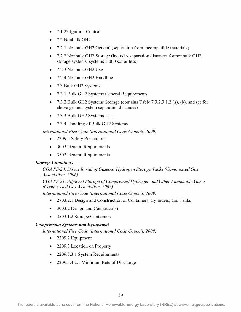
39
This report is available at no cost from the National Renewable Energy Laboratory (NREL) at www.nrel.gov/publications.
• 7.1.23 Ignition Control
• 7.2 Nonbulk GH2
• 7.2.1 Nonbulk GH2 General (separation from incompatible materials)
• 7.2.2 Nonbulk GH2 Storage (includes separation distances for nonbulk GH2 storage systems, systems 5,000 scf or less)
• 7.2.3 Nonbulk GH2 Use
• 7.2.4 Nonbulk GH2 Handling
• 7.3 Bulk GH2 Systems
• 7.3.1 Bulk GH2 Systems General Requirements
• 7.3.2 Bulk GH2 Systems Storage (contains Table 7.3.2.3.1.2 (a), (b), and (c) for above ground system separation distances)
• 7.3.3 Bulk GH2 Systems Use
• 7.3.4 Handling of Bulk GH2 Systems
International Fire Code (International Code Council, 2009) • 2209.5 Safety Precautions
• 3003 General Requirements
• 3503 General Requirements
Storage Containers CGA PS-20, Direct Burial of Gaseous Hydrogen Storage Tanks (Compressed Gas Association, 2006) CGA PS-21, Adjacent Storage of Compressed Hydrogen and Other Flammable Gases (Compressed Gas Association, 2005) International Fire Code (International Code Council, 2009)
• 2703.2.1 Design and Construction of Containers, Cylinders, and Tanks
• 3003.2 Design and Construction
• 3503.1.2 Storage Containers
Compression Systems and Equipment International Fire Code (International Code Council, 2009)
• 2209.2 Equipment
• 2209.3 Location on Property
• 2209.5.3.1 System Requirements
• 2209.5.4.2.1 Minimum Rate of Discharge
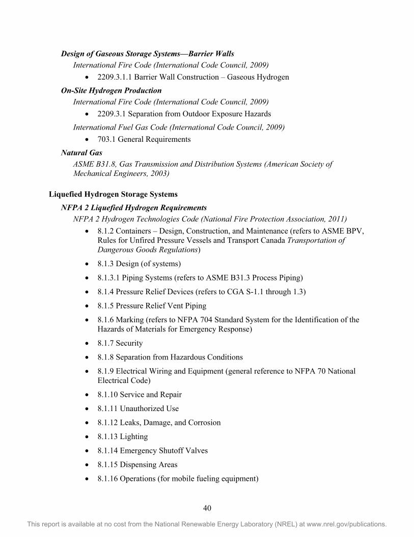
40
This report is available at no cost from the National Renewable Energy Laboratory (NREL) at www.nrel.gov/publications.
Design of Gaseous Storage Systems—Barrier Walls International Fire Code (International Code Council, 2009)
• 2209.3.1.1 Barrier Wall Construction – Gaseous Hydrogen
On-Site Hydrogen Production International Fire Code (International Code Council, 2009)
• 2209.3.1 Separation from Outdoor Exposure Hazards
International Fuel Gas Code (International Code Council, 2009) • 703.1 General Requirements
Natural Gas ASME B31.8, Gas Transmission and Distribution Systems (American Society of Mechanical Engineers, 2003)
Liquefied Hydrogen Storage Systems
NFPA 2 Liquefied Hydrogen Requirements NFPA 2 Hydrogen Technologies Code (National Fire Protection Association, 2011)
• 8.1.2 Containers – Design, Construction, and Maintenance (refers to ASME BPV, Rules for Unfired Pressure Vessels and Transport Canada Transportation of Dangerous Goods Regulations)
• 8.1.3 Design (of systems)
• 8.1.3.1 Piping Systems (refers to ASME B31.3 Process Piping)
• 8.1.4 Pressure Relief Devices (refers to CGA S-1.1 through 1.3)
• 8.1.5 Pressure Relief Vent Piping
• 8.1.6 Marking (refers to NFPA 704 Standard System for the Identification of the Hazards of Materials for Emergency Response)
• 8.1.7 Security
• 8.1.8 Separation from Hazardous Conditions
• 8.1.9 Electrical Wiring and Equipment (general reference to NFPA 70 National Electrical Code)
• 8.1.10 Service and Repair
• 8.1.11 Unauthorized Use
• 8.1.12 Leaks, Damage, and Corrosion
• 8.1.13 Lighting
• 8.1.14 Emergency Shutoff Valves
• 8.1.15 Dispensing Areas
• 8.1.16 Operations (for mobile fueling equipment)

41
This report is available at no cost from the National Renewable Energy Laboratory (NREL) at www.nrel.gov/publications.
• 8.2 Nonbulk LH2 (storage, handling and use shall be in accordance with Chapter 1–6 and 8 as applicable)
• 8.3 Bulk LH2 Systems (cutoff is = or > 150 liters)
• 8.3.1.2.1.1 Fire Resistance for Steel Supports
• 8.3.1.2.1.2 Container Marking
• 8.3.1.2.2 Vent System Requirements (including reference to CGAG-5.5)
• 8.3.1.2.3 Piping, Tubing, and Fittings (including reference to ASME B31.3 Process Piping)
• 8.3.1.2.4 Equipment Assembly (including location of emergency shutoff valves)
• 8.3.1.2.5 LH2 Vaporizers
• 8.3.1.2.6 Electrical Systems (sets electrically classified areas and refer to NFPA 70)
• 8.3.1.2.7 Bonding and Grounding
• 8.3.1.2.8 Stationary Pumps and Compressors
• 8.3.1.2.9 Emergency Shutdown System
• 8.3.2 Bulk LH2 Systems Storage
• 8.3.2.1.3 Placarding Site
• 8.3.2.1.4.1 Construction of the Inner Vessel
• 8.3.2.1.4.2 Construction of the Vacuum Jacket (Outer Vessel)
• 8.3.2.1.4.3 Nonstandard Containers (can be used with AHJ approval)
• 8.3.2.1.4.4 Concrete Containers
• 8.3.2.1.4.5 Foundations and Supports
• 8.3.2.2 Indoor Storage
• 8.3.2.2.2 Detaching Buildings (including requirements for explosion control)
• 8.3.2.3 Outdoor Storage
• 8.3.2.4 Aboveground Tanks
• 8.3.2.4.2 Physical Protection
• 8.3.2.4.3 Flood Protection
• 8.3.2.4.4 Drainage
• 8.3.2.4.5 Siting Locations (Including Table 8.3.2.4.5.1 Minimum Distance from Liquefied Hydrogen Systems to Exposures)
• 8.3.2.5 Underground Tanks

42
This report is available at no cost from the National Renewable Energy Laboratory (NREL) at www.nrel.gov/publications.
• 8.3.3 Bulk LH2 Systems Use
• 8.3.3.1.5 Inspection (requirements for annual inspection and recordkeeping)
• 8.3.4 Bulk LH2 Systems Handling
• 8.3.4.2 Carts and Trucks
• 8.3.4.4 Closed Containers
• 8.3.4.5 Cargo Transport Unloading
• 8.3.4.6 Overfilling
Liquid Hydrogen Storage—Equipment Location International Fire Code (International Code Council, 2009)
• 2209.3 Location on Property
• 3203.5.4 Physical Protection
• 3203.6 Separation from Hazardous Conditions
• 3204.3.1.1 Location
• 3204.4.2 Location
• 3504 Storage
Liquid Hydrogen Storage—Storage Containers International Fire Code (International Code Council, 2009)
• 2703.2 Systems, Equipment, and Processes
• 3203.1 Containers
• 3203.5 Security
• 3203.6 Separation from Hazardous Conditions
• 3204.3.1 Stationary Containers
• 3204.4 Underground Tanks
Dispensing Systems NFPA 2 Hydrogen Technologies Code (National Fire Protection Association, 2011)
• 10.2.1 System Approvals
• 10.3.1.1 System Component Qualifications
• 10.3.1.4 Pressure Relief Devices
• 10.3.1.5 Pressure Gauges
• 10.3.1.6 Pressure Regulators
• 10.3.1.7 Fuel Lines and Piping Systems

43
This report is available at no cost from the National Renewable Energy Laboratory (NREL) at www.nrel.gov/publications.
• 10.3.1.8 Hose and Hose Connections
• 10.3.1.9 Valves
• 10.3.1.10 System Testing
• 10.3.1.11 System Maintenance
• 10.3.1.12 Equipment Security and Vehicle Protection
• 10.3.1.13 Compressed and Gas Processing Systems
• 10.3.1.14 Vehicle Fueling Dispenser System Operation
• 10.3.1.15 Vehicle Fueling Connection
• 10.3.1.16 Installation of Electrical Equipment
• 10.3.1.17 Stray or Impressed Currents and Bonding
• 10.3.1 18 Installation of Emergency Shutdown Equipment
• 10.3.1.19 Fire Protection
• 10.3.2.2.3.1.3 Separation Distances for Outdoor Gaseous Hydrogen Dispensing Systems
Vaporizers International Fire Code (International Code Council, 2009)
• 2209.2 Equipment
• 2209.3 Location on Property
• 3203.1.3 Foundations and Supports
• 3203.2.2 Vessels or Equipment Other than Containers
• 3203.5.3 Securing of Vaporizers
International Fuel Gas Code (International Code Council, 2009) • 708 Design of Liquefied Hydrogen Systems Associated with Hydrogen
Vaporization Operations
Dispensing, Operations, and Maintenance Safety—Gaseous Hydrogen CGA G-5.5, Hydrogen Vent Systems (Compressed Gas Association, 2004)
• 9 Maintenance
International Fire Code (International Code Council, 2009) • 2204 Dispensing Operations
• 2209.4 Dispensing into Motor Vehicles at Self-Service Hydrogen Motor Fuel-Dispensing Facilities
NFPA 30A, Code for Motor Fuel Dispensing Facilities and Repair Garages (National Fire Protection Association, 2003)
• 9.2.2 Tank Filling and Bulk Delivery

44
This report is available at no cost from the National Renewable Energy Laboratory (NREL) at www.nrel.gov/publications.
• 9.4 Operating Requirements for Attended Self-Service Motor Fuel Dispensing Facilities
• 9.5 Operating Requirements for Unattended Self-Service Motor Fuel Dispensing Facilities
Dispensing, Operations, and Maintenance Safety—Liquid Hydrogen CGA G-5.5, Hydrogen Vent Systems (Compressed Gas Association, 2004)
• 9 Maintenance
International Fire Code (International Code Council, 2009) • 2204 Dispensing Operations
• 2209.4 Dispensing into Motor Vehicles at Self-Service Hydrogen Motor Fuel-Dispensing Facilities
NFPA 30A, Code for Motor Fuel Dispensing Facilities and Repair Garages (National Fire Protection Association, 2003)
• 9.2.2 Tank Filling and Bulk Delivery
• 9.4 Operating Requirements for Attended Self-Service Motor Fuel Dispensing Facilities
• 9.5 Operating Requirements for Unattended Self-Service Motor Fuel Dispensing Facilities
Piping and Tubing for All Systems ASME B31.12, Hydrogen Piping and Pipelines (American Society of Mechanical Engineers, 2012) ASME B31.3, Process Piping (American Society of Mechanical Engineers, 2006)
• F323.4(5) Specific Material Considerations—Metals
• IX K305 Pipe
CGA G-5.4, Standard for Hydrogen Piping Systems at Consumer Locations (Compressed Gas Association, 2005)
• 3.1 General
• 3.2 Piping Materials
• 5.0 Installation
• 5.1 Piping Installation General
• 5.2 Piping Installation Above Ground Installation
• 5.3 Piping Installation Underground Installation
International Fuel Gas Code (International Code Council, 2012) • 101.2.1 Gaseous Hydrogen Systems
• 704 Piping, Use, and Handling

45
This report is available at no cost from the National Renewable Energy Laboratory (NREL) at www.nrel.gov/publications.
705 Testing of Hydrogen Piping Systems CGA H-3 Cryogenic Hydrogen Storage (Compressed Gas Association, 2006)
• 10.0 External Piping
Valving and Fittings for All Systems
ASME B31.3, Process Piping (American Society of Mechanical Engineers, 2006) • IX K306 Fittings, Bends, and Branch Connections
• IX K307 Valves and Specialty Components
CGA G-5.4, Standard for Hydrogen Piping Systems at Consumer Locations (Compressed Gas Association, 2005)
• 3.3.2 Isolation Valves
• 3.3.3 Emergency Isolation Valves
• 3.3.4 Excess Flow Valves
• 3.3.5 Check Valves
• 3.3.7 Gasket and Sealing Materials
• 3.3.8 Additional Requirements
• 5.0 Installation
• 5.1 Installation General
Venting and Other Equipment
CGA G-5.5, Hydrogen Vent Systems (Compressed Gas Association, 2004) • 6.0 Vent System
• 6.2 Sizing
• 6.3 Design
• 6.4 Materials
• 6.5 Components
• 7 Installation
International Fire Code (International Code Council, 2009) • 2209.5.4 Venting of Hydrogen Systems
• 2211.8.1.2 Atmospheric Venting of Hydrogen from Motor Vehicle Fuel Storage Containers
• 3003.16.8 Connections
• 3005.5 Venting
• 3203.3 Pressure Relief Vent Piping

46
This report is available at no cost from the National Renewable Energy Laboratory (NREL) at www.nrel.gov/publications.
• 3204.4.5 Venting of Underground Tank Fire Safety
Construction International Fire Code (International Code Council, 2009)
• 911 Explosion Control
• 2209.5 Safety Precautions
International Fuel Gas Code (International Code Council, 2009) • 706.3 Outdoor Gaseous Hydrogen Systems
NFPA 52, Vehicular Gaseous Fuel Systems Code (National Fire Protection Association, 2010)
• 9.12 Stray or Impressed Currents and Bonding
NFPA 55, Compressed Gases and Cryogenic Fluids Code (National Fire Protection Association, 2010)
• 7.1.6 Separation from Hazardous Conditions
Equipment International Fire Code (International Code Council, 2009)
• 404 Fire Safety and Evacuation Plan
• 406 Employee Training and Response Procedures
• 407 Hazard Communication
• 906 Portable Fire Extinguishers
• 907 Fire Alarm and Detection Systems
• 2209.4 Dispensing into Motor Vehicles at Self-Service Hydrogen Motor Fuel-Dispensing Facilities
• 2209.5 Safety Precautions
Signage International Fire Code (International Code Council, 2009)
• 2204.3.5 Emergency Procedures
• 2209.5.2.1 Identification
CGA H-3 Cryogenic Hydrogen Storage (Compressed Gas Association, 2006) • 6.0 Tank Design and Manufacturing Criteria
• 7.0 Inner Vessel
• 8.0 Outer Jacket
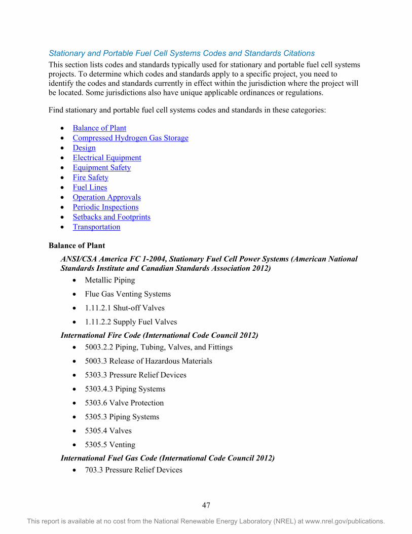
47
This report is available at no cost from the National Renewable Energy Laboratory (NREL) at www.nrel.gov/publications.
Stationary and Portable Fuel Cell Systems Codes and Standards Citations This section lists codes and standards typically used for stationary and portable fuel cell systems projects. To determine which codes and standards apply to a specific project, you need to identify the codes and standards currently in effect within the jurisdiction where the project will be located. Some jurisdictions also have unique applicable ordinances or regulations.
Find stationary and portable fuel cell systems codes and standards in these categories:
• Balance of Plant • Compressed Hydrogen Gas Storage • Design • Electrical Equipment • Equipment Safety • Fire Safety • Fuel Lines • Operation Approvals • Periodic Inspections • Setbacks and Footprints • Transportation
Balance of Plant
ANSI/CSA America FC 1-2004, Stationary Fuel Cell Power Systems (American National Standards Institute and Canadian Standards Association 2012)
• Metallic Piping
• Flue Gas Venting Systems
• 1.11.2.1 Shut-off Valves
• 1.11.2.2 Supply Fuel Valves
International Fire Code (International Code Council 2012) • 5003.2.2 Piping, Tubing, Valves, and Fittings
• 5003.3 Release of Hazardous Materials
• 5303.3 Pressure Relief Devices
• 5303.4.3 Piping Systems
• 5303.6 Valve Protection
• 5305.3 Piping Systems
• 5305.4 Valves
• 5305.5 Venting
International Fuel Gas Code (International Code Council 2012) • 703.3 Pressure Relief Devices

48
This report is available at no cost from the National Renewable Energy Laboratory (NREL) at www.nrel.gov/publications.
• 704 Piping, Use and Handling
International Mechanical Code (International Code Council 2012) • 305 Piping Support
• 401 General
• 501 Exhaust Systems
• 502 Required Systems
• 510 Hazardous Exhaust Systems
NFPA 55, Compressed Gases and Cryogenic Fluids Code (National Fire Protection Association 2013)
• 7.3.1.3 Piping Systems
• 7.3.1.4 Valves
• 10.2.3 Hydrogen-Venting Systems
• 10.2.3.1 Venting Requirements
NFPA 853, Standard for the Installation of Stationary Fuel Cell Power Systems (National Fire Protection Association 2010)
• 6.4.1 Gaseous Hydrogen Storage
• 6.4.3 Hydrogen Piping
• 6.4.3.6 Ventilation Air
• 7.1.1 General
• 7.2.2 When Natural Ventilation Permitted
• 7.3 Exhaust Systems
Compressed Hydrogen Gas Storage
International Building Code (International Code Council 2012) • 414.4 Hazardous Materials Systems
International Fire Code (International Code Council 2012) • 5003.2 Systems, Equipment, and Processes
• 5003.2.1 Design and Construction of Containers, Cylinders, and Tanks
• 5003.2.4 Installation of Tanks
• 5003.2.5 Empty Containers and Tanks
• 5003.4 Material Safety Data Sheets
• 5003.9.2 Security
• 5003.9.3 Protection from Vehicles

49
This report is available at no cost from the National Renewable Energy Laboratory (NREL) at www.nrel.gov/publications.
• 5003.9.9 Shelf Storage
• 5004 Storage
• 5303.1 Containers, Cylinders, and Tanks
• 5303.2 Design and Construction
• 5303.4.1 Stationary Compressed Gas Containers, Cylinders, and Tanks
• 5303.4.2 Portable Containers, Cylinders, and Tanks
• 5303.5 Security
• 5303.6.1 Compressed Gas Container, Cylinder, or Tank Protective Caps or Collars
• 5303.10 Unauthorized Use
• 5303.12 Leaks, Damage, or Corrosion
• 5303.13 Surface of Unprotected Storage or Use Areas
• 5303.14 Overhead Cover
• 5304 Storage of Compressed Gases
• 5305.1 Compressed Gas Systems
• 5803.1.2 Storage Containers
• 5803.1.3 Emergency Shutoff
• 5803.1.4 Ignition Source Control
International Fuel Gas Code (International Code Council 2012) • 303 Appliance Location
• 409 Shutoff Valves
• 703.2 Containers, Cylinders, and Tanks
• 703.5 Security
International Mechanical Code (International Code Council 2012) • 303 Equipment & Appliance Location
NFPA 55, Compressed Gases and Cryogenic Fluids Code (National Fire Protection Association 2010)
• 7.1.4 Listed and Approved Hydrogen Equipment
• 7.1.6 Containers, Cylinders and Tanks
• 10.3.2 Location of Gaseous Hydrogen Systems
NFPA 853, Standard for the Installation of Stationary Fuel Cell Power Systems (National Fire Protection Association 2010)
• 6.4.1 Gaseous Hydrogen Storage
• 6.4.3 Hydrogen Piping

50
This report is available at no cost from the National Renewable Energy Laboratory (NREL) at www.nrel.gov/publications.
• 6.4.3.1 Hydrogen Piping Shutoff Valve
• 6.4.3.2 Hydrogen Piping
• 6.4.3.5 Hydrogen Piping
• 6.4.3.7 Hydrogen Piping
Design
ANSI/CSA America FC 1-2004, Stationary Fuel Cell Power Systems (American National Standards Institute and Canadian Standards Association 2004)
• 1.2 Power Systems Design
• 1.3 Physical Environment and Operating Conditions
• 1.4 Selection of Materials
• 1.6 Cabinets
International Building Code (International Code Council 2012) • 307.1.1 Maximum Allowable Quantities
• 414.1 General
• 414.2 Control Areas
• 1609 Wind Loads
• 1612 Flood Loads
• 1808 Foundations
International Fire Code (International Code Council 2012) • 5003.1.1 Maximum Allowable Quantities per Control Area
• 5003.1.3 Quantities Not Exceeding the Maximum Allowable Quantity per Control Area
• 5003.1.4 Quantities Exceeding the Maximum Allowable Quantity per Control Area
• 5003.2.8 Seismic Protection
• 5003.8 Construction Requirements
• 5003.8.1 Buildings
• 5003.8.2 Required Detached Buildings
• 5003.8.3 Control Areas
• 5003.8.4 Gas Rooms
• 5003.8.5 Exhausted Enclosures
• 5003.8.6 Gas Cabinets
• 5003.8.7 Hazardous Materials Storage Cabinets

51
This report is available at no cost from the National Renewable Energy Laboratory (NREL) at www.nrel.gov/publications.
• 5004.12 Outdoor Storage
International Fuel Gas Code (International Code Council 2012) • 301 General
• 302 Structural Safety
• 633 Stationary Fuel Cell Power Systems
• 635 Gaseous Hydrogen Systems
International Mechanical Code (International Code Council 2012) • 301 General
• 302 Protection of Structure
• 924 Stationary Fuel Cell Power Systems
• 926 Gaseous Hydrogen Systems
NFPA 55, Compressed Gases and Cryogenic Fluids Code (National Fire Protection Association, 2010)
• 7.1.4 Listed and Approved Hydrogen Equipment
• 10.2.2 Piping Systems
NFPA 853, Standard for the Installation of Stationary Fuel Cell Power Systems (National Fire Protection Association 2010)
• 4.2 Prepackaged, Self-Contained Fuel Cell Power Systems
• 4.3 Pre-Engineered Fuel Cell Power Systems
• 4.4 Engineered and Field-Constructed Fuel Cell Power Systems
• 5.1.1 (2) General Siting
• 6.4.1 Gaseous Hydrogen Storage
Electrical Equipment
ANSI/CSA America FC 1-2004, Stationary Fuel Cell Power Systems (American National Standards Institute and Canadian Standards Association 2004)
• 1.12 Electrical Safety
International Fire Code (International Code Council, 2009) • 5003.9.4 Electrical Wiring and Equipment
• 5003.9.5 Static Accumulation
• 5303.8 Wiring and Equipment
• 5803.1.5 Electrical
International Fuel Gas Code (International Code Council 2012) • 703.4 Venting

52
This report is available at no cost from the National Renewable Energy Laboratory (NREL) at www.nrel.gov/publications.
• 703.6 Electrical Wiring and Equipment
NFPA 853, Standard for the Installation of Stationary Fuel Cell Power Systems (National Fire Protection Association 2007)
• 8.1.3 Electrical Equipment and Components
Equipment Safety
ANSI/CSA America FC 1-2004, Stationary Fuel Cell Power Systems (American National Standards Institute and Canadian Standards Association 2004)
• 1.3.3 Physical Environmental
• 1.3.6 System Purging
• 1.3.7 Vibration, Shock and Bump
• 1.3.8 Handling, Transportation, and Storage
• 1.3.9 Protection against Fire and Explosion Hazards
International Building Code (International Code Council 2012) • 414.6 Outdoor Storage, Dispensing, and Use
International Fire Code (International Code Council 2012) • 5003.1 Hazardous Materials
• 5003.2.3 Equipment, Machinery, and Alarms
• 5003.2.9 Testing
• 5003.9 General Safety Precautions
• 5003.9.1 Personnel Training and Written Procedures
• 5003.9.8 Separations of Incompatible Materials
• 5003.12 Outdoor Control Areas
• 5005 Use, Dispensing, and Handling
• 5303.7 Separations from Hazards
• 5305 Use and Handling of Compressed Gases
• 5305.2 Controls
• 5305.6 Upright Use
• 5305.7 Transfer
• 5305.9 Material-Specific Regulations
• 5305.10 Handling
• 5805 General Use

53
This report is available at no cost from the National Renewable Energy Laboratory (NREL) at www.nrel.gov/publications.
International Fuel Gas Code (International Code Council 2012) • 705 Testing of Hydrogen Piping Systems
• 706 Location of Gaseous Hydrogen Systems
NFPA 55, Compressed Gases and Cryogenic Fluids Code (National Fire Protection Association 2013)
• 7.1.11 Separation from Hazardous Conditions
• 7.6 Flammable Gases
NFPA 853, Standard for the Installation of Stationary Fuel Cell Power Systems (National Fire Protection Association 2010)
• 5.1.1 General Siting
• 5.1.2 General Siting
• 5.2 Outdoor Installations
• 9.2 Outdoor Installations
Fire Safety
ANSI/CSA America FC 1-2004, Stationary Fuel Cell Power Systems (American National Standards Institute and Canadian Standards Association 2012)
• 1.5 General Requirements
• 1.6 Cabinets
• 1.16 Marking, Labeling, and Packaging
• 1.16.2 FC Power System Marking
• 1.19.4.2 Installation Manual
International Building Code (International Code Council 2012) • 907 Fire Alarms and Detection Systems
International Fire Code (International Code Council 2012) • 401 General Emergency Planning and Preparedness
• 406 Employee Training and Response Procedures
• 5003.9.1.1 Fire Department Liaison
• 5303.4 Gas Marking
• 5303.11 Exposure to Fire
• 5303.16.13 Accessway
• 5503.4 Liquid Marking
International Fuel Gas Code (International Code Council 2012) • 305 Installation

54
This report is available at no cost from the National Renewable Energy Laboratory (NREL) at www.nrel.gov/publications.
International Mechanical Code (International Code Council 2012) • 304 Installation
NFPA 55, Compressed Gases and Cryogenic Fluids Code (National Fire Protection Association 2010)
• 7.1.8 Labeling Requirements
• 10.2.1 Marking
• 10.6.1.2 Fire Protection
NFPA 853, Standard for the Installation of Stationary Fuel Cell Power Systems (National Fire Protection Association 2010)
• 5.1.3 General Siting
• 5.2 Outdoor Installations
• 6.1.2 General
• 8.1.2 Fuel Cell Fire Protection and Detection
• 9.2 Outdoor Installations
• 9.5 Fire Protection
Fuel Lines
ANSI/CSA America FC 1-2012, Stationary Fuel Cell Power Systems (American National Standards Institute and Canadian Standards Association 2004)
• 1.8.1 Metallic Piping
NFPA 55, Compressed Gases and Cryogenic Fluids Code (National Fire Protection Association 20103
• 7.3.1.3 Piping Systems
NFPA 853, Standard for the Installation of Stationary Fuel Cell Power Systems (National Fire Protection Association 2010)
• 6.4.1 Gaseous Hydrogen Storage
• 6.4.3 Hydrogen Piping
Operation Approvals
ANSI/CSA America FC 1-2012, Stationary Fuel Cell Power Systems (American National Standards Institute and Canadian Standards Association, 2004)
• 1.16.1 Marking, Labeling and Packaging
• 1.16.2 FC Power System Marking
• 1.16.4.2 Installation Manual

55
This report is available at no cost from the National Renewable Energy Laboratory (NREL) at www.nrel.gov/publications.
CGA P-1, Safe Handling of Compressed Gases in Containers (Compressed Gas Association 2008)
• 4.4 Regulating Authorities of Employee Safety and Health
International Fire Code (International Code Council 20012 • 105.6.8 Compressed Gases
• 404.3.2 Fire Safety Plans
• 406 Employee Training and Response Procedures
• 5003.5 Hazard Identification Signs
• 5003.6 Signs
NFPA 55, Compressed Gases and Cryogenic Fluids Code (National Fire Protection Association 2013)
• 4.7 Personnel Training
• 4.8 Fire Department Liaison
• 7.1.8 Labeling Requirements
• 10.2.1 Marking
• 10.3.2 Location of Gaseous Hydrogen Systems
• 10.6.1.2 Fire Protection
NFPA 853, Standard for the Installation of Stationary Fuel Cell Power Systems (National Fire Protection Association 2010)
• 6.1.2 General
• 6.4.1 Gaseous Hydrogen Storage
• 6.4.3 Hydrogen Piping
• 8.2 Fire Prevention and Emergency Planning
Periodic Inspections
ANSI/CSA America FC 1-2012, Stationary Fuel Cell Power Systems (American National Standards Institute and Canadian Standards Association 2004)
• 1.16.4.5 Maintenance Manual
International Fire Code (International Code Council 2012) • 5003.2.6 Maintenance
• 5303.9 Service and Repair
International Fuel Gas Code (International Code Council 2012) • 707 Operation and Maintenance of Gaseous Hydrogen Systems

56
This report is available at no cost from the National Renewable Energy Laboratory (NREL) at www.nrel.gov/publications.
Setbacks and Footprints International Fire Code (International Code Council 2012)
• 5003.7 Separations from Hazards
• 5003.9.8 Separations of Incompatible Materials
• 5004 Storage of Compressed Gases
International Fuel Gas Code (International Code Council 2012) • 706 Location of Gaseous Hydrogen Systems
NFPA 55, Compressed Gases and Cryogenic Fluids Code (National Fire Protection Association 2013)
• 10.3.2 Locations
NFPA 853, Standard for the Installation of Stationary Fuel Cell Power Systems (National Fire Protection Association 2010)
• 6.4.1 Gaseous Hydrogen Storage
Transportation
CGA P-1, Safe Handling of Compressed Gases in Containers (Compressed Gas Association 2008)
• 4.1 Transportation Regulating Authorities
• 4.2 Container Regulations
• 4.3 Container Filling Regulations
• 6.2 Flammable Gases
International Fire Code (International Code Council 20012 • 105.6.8 Compressed Gases
• 404.3.2 Fire Safety Plans
• 5005 Use, Dispensing, and Handling
• 5305.7 Transfer
• 5805 General Use
NFPA 55, Compressed Gases and Cryogenic Fluids Code (National Fire Protection Association 2013)
• 7.3 Use and Handling
• 8.3.5 Overfilling
• 10.3.2 Location of Gaseous Hydrogen Systems

This report is available at no cost from the National Renewable Energy Laboratory (NREL) at www.nrel.gov/publications.
Example Permit Section 1 of the permit application requires basic identifying information be submitted.
Section 2 of the permit application identifies which code requirements need to be complied with depending on whether the dispenser is being added to an existing station or whether the dispenser is at a new stand-alone station.
The technical installation requirements address the following specific elements of station safety:
• Approval/listing and labeling requirements
• Piping code compliance
• Storage vessel stamps/approval. Section 3 consists of a standard certification statement that could be modified as needed by the jurisdiction. By signing the certification statement the applicant agrees to comply with the standard permit conditions and other applicable requirements. This consent would give the jurisdiction the option of allowing the applicant to proceed with installation and operation of the dispensing equipment.
Section 4 of the document gives an example of a checklist the jurisdiction could develop to track key information on the application. The example under Section 4 contains only a few items of the many that the jurisdiction might wish to track.
This permit package also includes a schematic drawing depicting a typical installation (Figure 2). The purpose of the schematic is only to show how the station equipment could be arranged and is not intended to convey any permit requirements.
Section 1. Basic Identifying Information
Jurisdiction of __________________, _____________(state)
Building/Fire Permit For Hydrogen Dispensing Installation Compliance with the following permit will allow the construction and operation of a hydrogen dispensing installation in the _________________ jurisdiction. This permit addresses the following situations:
1. The addition of a hydrogen dispensing and storage system to an existing fueling station 2. TBD
This permit contains a general reference to the fire and building codes or equivalent codes used in the jurisdiction. All work and installed equipment will comply with the requirements of XXXX code used in the jurisdiction. The jurisdiction maintains the authority/responsibility to conduct any inspections deemed necessary to protect public safety.
57

58
This report is available at no cost from the National Renewable Energy Laboratory (NREL) at www.nrel.gov/publications.
Section 2. Sample Permit Structure Topic Permit Requirements Siting Do storage and dispenser systems meet
separation distance requirements?
Mechanical Is equipment listed or approved? • Valves • Pressure relief devices • Piping • Containers • Hoses • Nozzles
Electrical Is equipment proximate to dispenser classified?
Maintenance Have maintenance requirements been defined in permit application? Is there documentation required?
Emergency response Are E-stops accessible? Do they have a plan? Are personnel trained? Is communication with the fire department and other emergency responders clearly defined?
Sensors Do sensors detect releases or upset conditions? Is the information from sensors conveyed to the process equipment, operators, and fire department?

This report is available at no cost from the National Renewable Energy Laboratory (NREL) at www.nrel.gov/publications.
Section 3. Owner Responsibility Statement
Section 4. Jurisdiction Checklist
I hereby certify that the electrical work described on this permit application shall be/has been installed in compliance with the conditions in this permit and the codes and standards currently adopted and enforced within the jurisdiction of installation. By agreeing to the above requirements, the licensee or owner shall be permitted to construct and operate the charging station. Signature of Owner Date
Information each jurisdiction would add to permit such as:
1. Unique requirements in the jurisdiction such as seismic requirements
2. Summary of Risk Management Plan (RMP) analysis if subject to RMP
3. Summary of compliance with environmental regulations if applicable.
59

60
This report is available at no cost from the National Renewable Energy Laboratory (NREL) at www.nrel.gov/publications.
Figure 2. Schematic of a typical hydrogen dispensing station with single dispenser with gaseous
and liquid hydrogen storage

61
This report is available at no cost from the National Renewable Energy Laboratory (NREL) at www.nrel.gov/publications.
References Austin, G. (1984). Shreve's Chemical Process Industries. New York: McGraw-Hill, Inc.
Cramer, S.D.; Covino, B.S., Jr. (2003). Corrosion: Fundamentals, Testing, and Protection. ASM Handbook Volume 13a. Materials Park, OH: ASM International.
Larminie, J.; Dicks, A. (2003). Fuel Cell Systems Explained. Chichester, West Sussex, England: John Wiley & Sons Ltd.
Lewis, R.J., Sr. (2001). Hawley’s Condensed Chemical Dictionary. New York: John Wiley & Sons, Inc.
McCarty, R.D.; Hord, J.; Roder, H.M. (1981). Selected Properties of Hydrogen (Engineering Design Data). Washington, DC: U.S. Department of Commerce, National Bureau of Standards.
National Fire Protection Association. (1963). NFPA 567 Gaseous Hydrogen Systems at Consumer Sites. Boston: National Fire Protection Association.
Ramachandran, R.; Menon, R.K. (1998). “An Overview of Industrial Uses of Hydrogen.” International Journal of Hydrogen Energy (23:7); pp. 593-598.
Rigden, J.S. (2003). Hydrogen: The Essential Element. Boston: Harvard University Press.
U.S. Census Bureau. (2012). “Transportation.” Statistical Abstract of the United States: 2012. Washington, DC: U.S. Census Bureau.
Wolff, D. (2008). “Expanding Use of Onsite UHP Hydrogen Production Improves Safety, Quality and Productivity in Epitaxy Operations.” 41st International Symposium on Microelectronics 2008 (IMAPS 2008); November 2-6, 2008, Providence, Rhode Island. Washington, DC: International Microelectronics and Packaging Society (IMAPS); pp. 405-412.
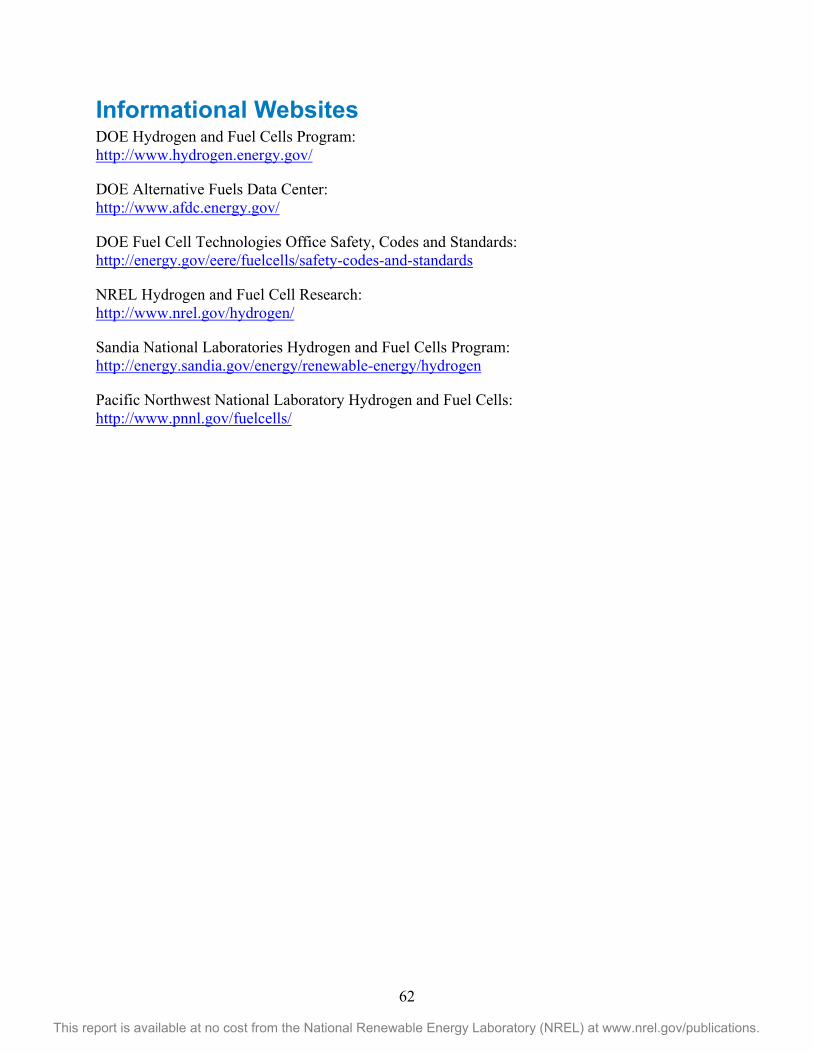
62
This report is available at no cost from the National Renewable Energy Laboratory (NREL) at www.nrel.gov/publications.
Informational Websites DOE Hydrogen and Fuel Cells Program: http://www.hydrogen.energy.gov/
DOE Alternative Fuels Data Center: http://www.afdc.energy.gov/
DOE Fuel Cell Technologies Office Safety, Codes and Standards: http://energy.gov/eere/fuelcells/safety-codes-and-standards
NREL Hydrogen and Fuel Cell Research: http://www.nrel.gov/hydrogen/
Sandia National Laboratories Hydrogen and Fuel Cells Program: http://energy.sandia.gov/energy/renewable-energy/hydrogen
Pacific Northwest National Laboratory Hydrogen and Fuel Cells: http://www.pnnl.gov/fuelcells/

63
This report is available at no cost from the National Renewable Energy Laboratory (NREL) at www.nrel.gov/publications.
Appendix A. NREL Process Hazard Analysis on a Representative Hydrogen Fueling Station The National Renewable Energy Laboratory (NREL) conducted a process hazard analysis (PHA) on a representative hydrogen fueling system (Figure A-1) to better understand the relative risks of the pieces of the system. The following analysis gives a picture of the components of most concern in a hydrogen fueling system.
Figure A-1. Schematic of a representative hydrogen station
A PHA was conducted on the representative station shown in Figure A-1. The analysis was performed by NREL staff familiar with operating hydrogen fueling stations and component safety and performance issues. NREL employed PHAWorks 5, a spreadsheet software package designed to perform risk analyses.

64
This report is available at no cost from the National Renewable Energy Laboratory (NREL) at www.nrel.gov/publications.
The analysis was based on the assumption that the system complied with the requirements of codes and standards typically used in the United States. These documents include the following:
• NFPA 2 Hydrogen Technologies Code
• International Fire Code—addresses hydrogen applications
• International Building Code—general construction requirements
• ASME B31.12 Hydrogen Pipelines and Piping Code—hydrogen piping design
• ASME BPV Code Section XIII and X Pressure Vessels
• CGA S-1.1-3 Pressure Relief—hydrogen storage systems
• NFPA 70 National Electric Code—classified electrical areas.
Table A-1 shows the preliminary results of the PHA. Figure A-2 and Table A-2 show the hazard assessment and frequency categories used in the PHA. The system was broken down into the eight nodes shown in Table A-1. Undesirable outcomes were identified based on defining variations at nodes. Safety measures were identified for these undesired outcomes. The residual risk was then defined for each undesirable outcome. The residual risk is based on assigning a consequence and probability using the rating system shown in Table A-2. The combination of consequence and probability produces a risk rating as determined by the risk matrix.
Table A-1. Risk Value Frequencies
Node/Parameter HR MR LR RR Sum Node 1 Dispensing Nozzle 0 0 5 1 6 Flow 0 0 5 1 6 Temperature 0 0 0 0 0 Node 2 Dispensing Hose 0 2 3 0 5 Flow 0 2 3 0 5 Node 3 Dispenser Cabinet 0 0 0 0 0 Flow 0 0 0 0 0 Node 4 Cascade tanks to Dispenser 0 0 2 5 7 Flow 0 0 0 1 1 Temperature 0 0 2 4 6 Node 5 Compression to Cascade Tanks 0 0 7 9 16 Pressure 0 0 7 9 16 Node 6 Cryogenic Storage to Compressors 0 0 0 1 1 Temperature 0 0 0 1 1 Node 7 Air System 0 0 0 5 5 Flow 0 0 0 5 5 Node 8 Control Electronics 0 0 2 4 6 Level 0 0 2 4 6 PROJECT TOTAL 0 2 19 25 46

65
This report is available at no cost from the National Renewable Energy Laboratory (NREL) at www.nrel.gov/publications.
The PHA used the risk evaluation system shown in Figure A-2. This matrix integrates event severity and event frequency to produce four categories of risk. These categories are High Risk (HR), Medium Risk (MR), Low Risk (LR), and Routine Risk (RR).
Probability
Con
sequ
ence
s
Category
Descriptive Word
A Frequent
B Reasonably Probable
C Occasional
D Remote
E Extremely Remote
F Impossible
I
Catastrophic
Hose rupture
II
Critical
Nozzle leak
III
Marginal
Compressor failure
IV
Negligible
High Risk Moderate Risk Low Risk Routine Risk
Figure A-2. NREL risk matrix
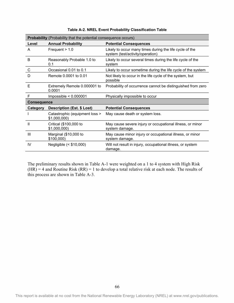
66
This report is available at no cost from the National Renewable Energy Laboratory (NREL) at www.nrel.gov/publications.
Table A-2. NREL Event Probability Classification Table
Probability (Probability that the potential consequence occurs) Level Annual Probability Potential Consequences A Frequent > 1.0 Likely to occur many times during the life cycle of the
system (test/activity/operation) B Reasonably Probable 1.0 to
0.1 Likely to occur several times during the life cycle of the system
C Occasional 0.01 to 0.1 Likely to occur sometime during the life cycle of the system D Remote 0.0001 to 0.01 Not likely to occur in the life cycle of the system, but
possible E Extremely Remote 0.000001 to
0.0001 Probability of occurrence cannot be distinguished from zero
F Impossible < 0.000001 Physically impossible to occur Consequence Category Description (Est. $ Lost) Potential Consequences I Catastrophic (equipment loss >
$1,000,000) May cause death or system loss.
II Critical ($100,000 to $1,000,000)
May cause severe injury or occupational illness, or minor system damage.
III Marginal ($10,000 to $100,000)
May cause minor injury or occupational illness, or minor system damage.
IV Negligible (< $10,000) Will not result in injury, occupational illness, or system damage.
The preliminary results shown in Table A-1 were weighted on a 1 to 4 system with High Risk (HR) = 4 and Routine Risk (RR) = 1 to develop a total relative risk at each node. The results of this process are shown in Table A-3.

67
This report is available at no cost from the National Renewable Energy Laboratory (NREL) at www.nrel.gov/publications.
Table A-3. Total Risk at Node
Node Node Description HR MR LR RR Node Total Risk
5 Compressor to Cascade Tank
0 0 7 9 23
2 Hose 0 2 3 0 12 1 Nozzle 0 0 5 1 11 4 Cascade Tanks to
Dispenser 0 0 2 5 9
8 Control Electronics 0 0 2 4 8 7 Air System 0 0 0 5 5 6 Cryo Storage to
Compressor 0 0 0 1 1
3 Dispenser Cabinet (evaluated under control electronics)
0 0 0 0 0
HR - High Risk
MR - Medium Risk
LR - Low Risk
RR - Routine Risk