Hydrogen Storage in New Metal Organic...
9
Hydrogen Storage in New Metal−Organic Frameworks David J. Tranchemontagne, † Kyo Sung Park, † Hiroyasu Furukawa,* ,†,⊥ Juergen Eckert, § Carolyn B. Knobler, † and Omar M. Yaghi †,‡,⊥ † Center for Reticular Chemistry, UCLA−DOE Institute for Genomics and Proteomics, and Department of Chemistry and Biochemistry, University of California−Los Angeles, 607 East Charles E. Young Drive, Los Angeles, California 90095, United States ‡ NanoCentury KI and Graduate School of EEWS (WCU) KAIST, Daejeon 305-701, Korea § Department of Chemistry, 4202 East Fowler Avenue, University of South Florida, Tampa, Florida 33620, United States * S Supporting Information ABSTRACT: Five new metal−organic frameworks (MOFs, termed MOF-324, 325, 326 and IRMOF-61 and 62) of either short linkers (pyrazolecarboxylate and pyrazaboledicarboxy- late) or long and thin alkyne functionalities (ethynyldibenzoate and butadiynedibenzoate) were prepared to examine their impact on hydrogen storage in MOFs. These compounds were characterized by single-crystal X-ray diffraction, and their low- pressure and high-pressure hydrogen uptake properties were investigated. In particular, volumetric excess H 2 uptake by MOF-324 and IRMOF-62 outperforms MOF-177 up to 30 bar. Inelastic neutron-scattering studies for MOF-324 also revealed strong interactions between the organic links and hydrogen, in contrast to MOF-5 where the interactions between the Zn 4 O unit and hydrogen are the strongest. These data also show that smaller pores and polarized linkers in MOFs are indeed advantageous for hydrogen storage. ■ INTRODUCTION To date, as a result of environmental concerns over fossil fuel consumption, increasing attention has been given to utilization of cleaner energy sources, such as methane and hydrogen. 1 The storage of hydrogen in porous materials is advantageous since it can be compacted within the pores. 2 Metal−organic frame- works (MOFs) 3 offer many opportunities for testing the effect of pore size and functionality on the hydrogen storage capacity. We can take advantage of the versatile nature of MOF chemistry by changing the combination of organic links and metal sources, allowing various pore dimensions and functionalities to be obtained. Pore size distributions in many MOFs are greater than 10 Å, owing in part to the large dimensions of the secondary building unit (SBU); the distance between two carboxylate carbons in the SBUs (e.g., 8.5 Å for Zn 4 O(CO 2 ) 6 , 3a 6.7 Å for Cu 2 (CO 2 ) 4 ) 4 is close to the definition of ultramicropore (<7 Å). 5 On the other hand, some MOFs have smaller pore diameters, leading to moderately stronger adsorbent−adsorbate interactions. Despite this, such materials usually have either slow gas diffusion rates or low surface areas. The size and functionalizations of the micropores must both be optimized to best utilize the walls of the adsorbents without losing the intrinsic porosity of the MOFs. In this study, we focused on making MOFs with small pores from either short organic links or from long thin links which would allow interpenetration that leads to small pores, as depicted in Scheme 1. Using the organic links 4-pyrazolecar- boxylic acid (H 2 PyC), 2,8-pyrazaboledicarboxylic acid (H 2 PzDC), 4,4,8,8-tetraethyl-2,8-pyrazaboledicarboxylic acid (H 2 Et-PzDC), ethynyldibenzoic acid (H 2 EDB), and butadiy- nedibenzoic acid (H 2 BDB), we synthesized five new MOFs: Zn 3 (OH)[(PyC) 2 (HPyC)] (MOF-324) and Cu 3 [(Cu 3 O)- (PyC) 3 (NO 3 )] 2 (MOF-325), based on in situ formation of a short organic link to provide small pores, Zn 4 O(Et-PzDC) 3 (MOF-326), which utilizes the polarizable pyrazabole unit, Zn 4 O(EDB) 3 (IRMOF-61), and Zn 4 O(BDB) 3 (IRMOF-62), which impart interpenetration through alkyne-containing links to affect the pore size. The structures of these MOFs produced by solvothermal reactions were determined by single-crystal X- ray diffraction analyses. In particular, both MOF-324 and IRMOF-62 have small pores and high surface areas and excellent cryogenic H 2 (77 K) uptakes at 1 bar. Based on the Received: March 12, 2012 Revised: May 19, 2012 Published: May 24, 2012 Scheme 1. Short Dicarboxylic Acids Used in MOF Synthesis: (a) Oxalic Acid, (b) Acetylene Dicarboxylic Acid, (c) Terephthalic Acid, and (d) 4-Pyrazolecarboxylic Acid (H 2 PyC) Article pubs.acs.org/JPCC © 2012 American Chemical Society 13143 dx.doi.org/10.1021/jp302356q | J. Phys. Chem. C 2012, 116, 13143−13151
Transcript of Hydrogen Storage in New Metal Organic...

Hydrogen Storage in New Metal−Organic FrameworksDavid J. Tranchemontagne,† Kyo Sung Park,† Hiroyasu Furukawa,*,†,⊥ Juergen Eckert,§
Carolyn B. Knobler,† and Omar M. Yaghi†,‡,⊥
†Center for Reticular Chemistry, UCLA−DOE Institute for Genomics and Proteomics, and Department of Chemistry andBiochemistry, University of California−Los Angeles, 607 East Charles E. Young Drive, Los Angeles, California 90095, United States‡NanoCentury KI and Graduate School of EEWS (WCU) KAIST, Daejeon 305-701, Korea§Department of Chemistry, 4202 East Fowler Avenue, University of South Florida, Tampa, Florida 33620, United States
*S Supporting Information
ABSTRACT: Five new metal−organic frameworks (MOFs,termed MOF-324, 325, 326 and IRMOF-61 and 62) of eithershort linkers (pyrazolecarboxylate and pyrazaboledicarboxy-late) or long and thin alkyne functionalities (ethynyldibenzoateand butadiynedibenzoate) were prepared to examine theirimpact on hydrogen storage in MOFs. These compounds werecharacterized by single-crystal X-ray diffraction, and their low-pressure and high-pressure hydrogen uptake properties wereinvestigated. In particular, volumetric excess H2 uptake byMOF-324 and IRMOF-62 outperforms MOF-177 up to 30bar. Inelastic neutron-scattering studies for MOF-324 also revealed strong interactions between the organic links and hydrogen,in contrast to MOF-5 where the interactions between the Zn4O unit and hydrogen are the strongest. These data also show thatsmaller pores and polarized linkers in MOFs are indeed advantageous for hydrogen storage.
■ INTRODUCTIONTo date, as a result of environmental concerns over fossil fuelconsumption, increasing attention has been given to utilizationof cleaner energy sources, such as methane and hydrogen.1 Thestorage of hydrogen in porous materials is advantageous since itcan be compacted within the pores.2 Metal−organic frame-works (MOFs)3 offer many opportunities for testing the effectof pore size and functionality on the hydrogen storage capacity.We can take advantage of the versatile nature of MOFchemistry by changing the combination of organic links andmetal sources, allowing various pore dimensions andfunctionalities to be obtained. Pore size distributions in manyMOFs are greater than 10 Å, owing in part to the largedimensions of the secondary building unit (SBU); the distancebetween two carboxylate carbons in the SBUs (e.g., 8.5 Å forZn4O(CO2)6,
3a 6.7 Å for Cu2(CO2)4)4 is close to the definition
of ultramicropore (<7 Å).5 On the other hand, some MOFshave smaller pore diameters, leading to moderately strongeradsorbent−adsorbate interactions. Despite this, such materialsusually have either slow gas diffusion rates or low surface areas.The size and functionalizations of the micropores must both beoptimized to best utilize the walls of the adsorbents withoutlosing the intrinsic porosity of the MOFs.In this study, we focused on making MOFs with small pores
from either short organic links or from long thin links whichwould allow interpenetration that leads to small pores, asdepicted in Scheme 1. Using the organic links 4-pyrazolecar-boxylic acid (H2PyC), 2,8-pyrazaboledicarboxylic acid(H2PzDC), 4,4,8,8-tetraethyl-2,8-pyrazaboledicarboxylic acid
(H2Et-PzDC), ethynyldibenzoic acid (H2EDB), and butadiy-nedibenzoic acid (H2BDB), we synthesized five new MOFs:Zn3(OH)[(PyC)2(HPyC)] (MOF-324) and Cu3[(Cu3O)-(PyC)3(NO3)]2 (MOF-325), based on in situ formation of ashort organic link to provide small pores, Zn4O(Et-PzDC)3(MOF-326), which utilizes the polarizable pyrazabole unit,Zn4O(EDB)3 (IRMOF-61), and Zn4O(BDB)3 (IRMOF-62),which impart interpenetration through alkyne-containing linksto affect the pore size. The structures of these MOFs producedby solvothermal reactions were determined by single-crystal X-ray diffraction analyses. In particular, both MOF-324 andIRMOF-62 have small pores and high surface areas andexcellent cryogenic H2 (77 K) uptakes at 1 bar. Based on the
Received: March 12, 2012Revised: May 19, 2012Published: May 24, 2012
Scheme 1. Short Dicarboxylic Acids Used in MOF Synthesis:(a) Oxalic Acid, (b) Acetylene Dicarboxylic Acid, (c)Terephthalic Acid, and (d) 4-Pyrazolecarboxylic Acid(H2PyC)
Article
pubs.acs.org/JPCC
© 2012 American Chemical Society 13143 dx.doi.org/10.1021/jp302356q | J. Phys. Chem. C 2012, 116, 13143−13151

inelastic neutron-scattering (INS) experiments, we reveal thatMOF-324 demonstrates strong interactions between hydrogenand the host material in comparison to MOF-5, which alsosupported the data from the isosteric heats of H2 adsorption(Qst).
6a
■ EXPERIMENTAL SECTIONOrganic Links. 4-Pyrazolecarboxylic acid (H2PyC) was
purchased from Aldrich. 2,8-Pyrazaboledicarboxylic acid(H2PzDC) and 4,4,8,8-tetraethyl-2,8-pyrazaboledicarboxylicacid (H2Et-PzDC) were synthesized according to literaturemethods.7 Synthetic procedures and characterization of H2EDBand H2BDB are described in the Supporting Information. Themolecular structures of these links are depicted in Figure 1.Synthesis and Characterization of MOFs and IRMOFs.
For easy reference, the formulas for three MOFs and twoIRMOFs and their crystal unit cell parameters are listed inTable 1. Zinc nitrate tetrahydrate was purchased from EMscience. Copper nitrate hemipentahydrate, zinc acetatedihydrate, N,N-dimethylformamide (DMF), 1-methyl-2-pyrro-
lidinone (NMP), and triethylamine were purchased from FisherScientific. N,N-Diethylformamide (DEF) was obtained fromBASF. All purchased materials were used without furtherpurification. Thermogravimetric analyses (TGA) were per-formed on a TA Q500 thermal analysis system with the sampleheld in a platinum pan in a continuous nitrogen flowatmosphere. Fourier transform infrared (FT-IR) spectra wereobtained by using a Nicolet FT-IR Impact 400 system and KBrpellet samples. The elemental analysis (EA) was performedusing a Thermo Flash EA1112 combustion CHNS analyzer.
Powder and Single-Crystal X-ray Diffraction Analyses.Powder X-ray diffraction (PXRD) patterns were collected witha Bruker AXS D8 Advanced diffractometer operated at 40 kVand 40 mA with monochromated Cu Kα radiation (λ = 1.540 6Å) and with a scan speed of 1 s/step and a step size of 0.05°.The simulated PXRD patterns were calculated from single-crystal data using the PowderCell 2.3 software suite.8
Single-crystal X-ray diffraction (SXRD) data were collectedon a Bruker SMART Apex diffractometer equipped with aCCD area detector and operated at 1800 W power (45 kV, 40
Figure 1. Molecular structures of organic links and their abbreviations (left). These links are connected with SBUs (middle) to form MOFs, whoseX-ray single-crystal structures are shown at the right. The yellow sphere represents the largest sphere that would occupy the cavity withoutcontacting the interior van der Waals surface. Zn, blue polyhedron; Cu, blue; O, red; C, black; B, orange; N, green; all hydrogen atoms are omittedfor clarity.
The Journal of Physical Chemistry C Article
dx.doi.org/10.1021/jp302356q | J. Phys. Chem. C 2012, 116, 13143−1315113144

mA) to generate (graphite-monochromated) Mo Kα radiation(λ = 0.710 73 Å). The data were collected with phi and omegascans. The frames were integrated using the Bruker SAINTSoftware package (Ver. 6.01). The reflection data werecorrected for absorption by using Bruker SADABS and solvedwith the Bruker SHELXTL (Ver. 6.14) Software package usingdirect methods.Adsorption Measurements. Low-pressure N2, Ar, and H2
adsorption measurements (up to 760 torr) were performed onan Autosorb-1 (Quantachrome) volumetric analyzer.6b,c Liquidnitrogen and argon baths were used for N2 and H2 (77 K) andAr and H2 (87 K). Gravimetric high-pressure H2 adsorptionisotherms were measured by use of GHP-300 from the VTICorporation.6b,c A Rubotherm magnetic suspension balanceMC-5 was used to measure the change in mass of samplessuspended within a tube under a chosen atmosphere. When H2gas was used, condensable impurities were removed with aliquid nitrogen trap. The adsorbate was added incrementally,and data points were recorded when no further change in masswas observed. To obtain the excess adsorption isotherm, alldata points were corrected for buoyancy and for the thermalgradient that arises between the balance (313 K) and thesample bucket.6b,c Ultrahigh-purity grade N2, Ar, H2, and He(99.999% purity) gases were used throughout the adsorptionexperiments.Inelastic Neutron Scattering. Inelastic neutron-scattering
(INS) spectra were collected at a temperature of 10 K on thequasielastic neutron spectrometer at the Intense PulsedNeutron Source (IPNS) at Argonne National Laboratory.Successive loading of material with hydrogen was carried out insitu at 77 K after first obtaining a spectrum of the “blank”sample. The spectra shown in Figure 6 were obtained bysubtracting the blank spectrum.Zn3(OH)[(PyC)2(HPyC)]·(DMF)(H2O)5, MOF-324. A solid
mixture of Zn(NO3)2·4H2O (190 mg, 0.72 mmol) andH2PzDC (63 mg, 0.25 mmol) was dissolved in 11.5 mL ofDMF and 6.5 mL of H2O (2:1 v/v) in a 20 mL vial. The vialwas delivered to a 100 °C isotherm oven and heated for 24 h.Colorless cubic crystals were collected and washed with DMF
(3 × 5 mL). Yield: 70 mg (59% based on H2PzDC). EA: Calcdfor C15H25N7O13Zn3: C, 25.46; H, 3.56; N, 13.86%. Found: C,25.27; H, 4.56; N, 14.58%. FT-IR (KBr pellet) 3424 (br), 3129(sh), 2956 (sh), 2803 (sh), 2487(sh), 1658 (sh), 1550 (vs),1443 (s), 1342 (w), 1286 (s), 1051 (m), 1005 (m), 888 (w),791 (s), 619 (w) cm−1.For porosity measurements, as-synthesized MOF-324 was
rinsed with DMF and immersed in anhydrous methanol for 3days, during which the activation solvent was decanted andfreshly replenished three times. The solvent was removed undervacuum at 85 °C, yielding porous material.
Cu3[(Cu3O)(PyC)3(NO3)]2·(DEF)18(NMP)3(H2O)8, MOF-325. A solid mixture of Cu(NO3)2·2.5H2O (170 mg, 0.73mmol) and H2PyC (30 mg, 0.27 mmol) were dissolved in DEF7.5 mL and NMP 7.5 mL in a 20 mL vial. The vial wasdelivered to an 85 °C isotherm oven and heated for 24 h. Deepblue truncated octahedral crystals were collected and washedwith DEF (3 × 5 mL). Yield: 81 mg (53% based on H2PyC).EA: Calcd for C129H253N35O47Cu9: C, 42.44; H, 6.99; N13.43%. Found: C, 42.2; H, 7.15; N, 13.21%. FT-IR (KBrpellet) 3426 (br), 2976 (m), 2935 (m), 1662 (s), 1601 (m),1540 (m), 1448 (m), 1387 (w), 1377 (w), 1296 (m), 1179 (w),1118 (w), 1056 (w), 1005 (w), 888 (w), 817(w), 792 (m), 756(w), 664 (w), 624 (w), 562 (w), 476 (w) cm−1.
Zn4O(Et-PzDC)3·(DMF)16(H2O)3, MOF-326. A mixture ofZn(NO3)2·4H2O (150 mg, 0.55 mmol) and H2Et-PzDC (50mg, 0.14 mmol) were dissolved in DMF 15 mL in a 20 mL vial.The vial was delivered to a 100 °C isotherm oven and heatedfor 24 h. Colorless cubic crystals were collected and washedwith DMF (3 × 5 mL). Yield: 51 mg (64% based on H2Et-PzDC). EA: Calcd for C96H190N28O32B6Zn4: C, 44.78; H, 7.44;N, 15.23%. Found: C, 44.88; H, 7.16; N, 15.51%. FT-IR (KBrpellet) 3435 (br), 3134 (sh), 2946 (s), 2869 (sh), 1662 (s),1561 (vs), 1454 (s), 1387 (w), 1306 (s), 1255 (s), 1107 (m),1062 (w), 1016 (w), 909 (w), 853 (m), 787 (m), 664 (w)cm−1.For porosity measurements, as-synthesized MOF-326 was
rinsed with DMF and immersed in chloroform for three days,during which the activation solvent was decanted and freshlyreplenished three times. The solvent was removed undervacuum at 85 °C, yielding porous material.
Zn4O(EDB)3·(DMF)17(H2O)7, IRMOF-61. Single Crystal. Amixture of H2EDB (4.6 mg, 0.017 mmol) and Zn(NO3)2·4H2O(17 mg, 0.064 mmol) was dissolved in DEF (1.0 mL) in a 4 mLvial. The vial was tightly capped with a Teflon-lined cap andplaced in an 85 °C oven overnight. A crystal was mounted in aglass capillary, which was sealed with a small amount of motherliquor.Bulk Scale. A mixture of H2EDB (230 mg, 0.85 mmol) and
Zn(NO3)2·4H2O (810 mg, 3.1 mmol) was dissolved in DEF(75 mL) in a 120 mL vial fitted with a Teflon-lined cap. Thesolution was heated in an 85 °C oven for three days, after whichtime the hot mother liquor was decanted and DMF was added.PXRD analysis showed that the pattern matched the patternsimulated from single-crystal data. EA: Calcd forC99H157N17O37Zn4: C, 48.75; H, 6.49; N, 9.76%. Found: C,48.65; H, 6.46; N, 9.78%. FT-IR (KBr pellet) 2930 (m), 1663(s), 1591 (s), 1546 (s) cm−1.For porosity measurements, as-synthesized IRMOF-61 was
rinsed with DMF and immersed in dichloromethane. Thesolvent was exchanged three times over six days. The solventwas removed at 75 °C under vacuum, yielding the porousmaterial.
Table 1. Crystal Structure Data for Synthesized MOFs
MOForganiclink
chemical formulaa
space group; a, b, c (Å)
α, β, γ (deg); V (Å3); Z
MOF-324 PyC Zn3(OH)[(PyC)2(HPyC)]·(DMF)(H2O)5Pa3 ; 20.123, 20.123, 20.123
90, 90, 90; 8148.5; 8MOF-325 PyC Cu3[(Cu3O)
(PyC)3(NO3)]2·(DEF)18(NMP)3(H2O)8Fm3m; 42.606, 42.606, 42.606
90, 90, 90; 77342; 16MOF-326 Et-PzDC Zn4O(Et-PzDC)3·(DMF)16(H2O)3
Fm3m; 33.410, 33.410, 33.41090, 90, 90; 37294; 8
IRMOF-61 EDB Zn4O(EDB)3·(DMF)17(H2O)7P42/ncm; 19.7213, 19.7213, 39.411
90, 90, 90; 15328.0; 4IRMOF-62 BDB Zn4O(BDB)3·(DMF)10(H2O)3
P3212; 31.114, 31.114, 39.28090, 90, 120; 32931; 12
aDMF = N,N-dimethylformamide; DEF = N,N-diethylformamide;NMP = 1-methyl-2-pyrrolidinone.
The Journal of Physical Chemistry C Article
dx.doi.org/10.1021/jp302356q | J. Phys. Chem. C 2012, 116, 13143−1315113145

Zn4O(BDB)3·(DMF)10(H2O)3, IRMOF-62. Single Crystal. Amixture of H2BDB (5.3 mg, 0.018 mmol) and Zn(NO3)2·4H2O(15 mg, 0.057 mmol) was mixed in a pyrex tube with DEF (1.0mL). The mixture was frozen (LN2), evacuated to 15 mtorr,flame-sealed under static vacuum, thawed, and placed in an 85°C oven for 6 days. A crystal was mounted in a glass capillarywhich was sealed with a small amount of mother liquor.Solvothermal Synthesis. A mixture of H2BDB (55 mg, 0.19
mmol), Zn(NO3)2·4H2O (17 mg, 0.63 mmol), and triethyl-amine (22 μL) was mixed in DMF (20 mL) in a vial which wastightly capped. The mixture was sonicated for 15 min andplaced in an 85 °C oven for 2 days, after which time the motherliquor was decanted and fresh DMF was added. PXRD analysisof the sample showed a match to the pattern simulated fromthe single-crystal data. EA: Calcd for C84H100N10O26Zn4: C,53.77; H, 5.28; N, 7.22%. Found: C, 52.49; H, 5.32; N, 7.26%.FT-IR (KBr) 2936 (m), 2223 (w), 2152 (w), 1678 (s), 1608(s), 1550 (s) cm−1.For porosity measurements, as-synthesized IRMOF-62 was
rinsed with DMF and immersed in dichloromethane. Thesolvent was exchanged three times over six days. The solventwas removed at 150 °C under vacuum, yielding the porousmaterial.Room Temperature Synthesis. A mixture of H2BDB (10.2 g,
35.1 mmol) and Zn(OAc)2·2H2O was stirred in DMF (650mL) for 16 h. A sample was collected for PXRD analysis. Thepeaks were found to match those of the simulated pattern. Thepowder was collected by filtration, rinsed with DMF and thenwith dichloromethane, and immersed in dichloromethane. Thesolvent was refreshed three times over six days. The productwas filtered and activated under vacuum (15 mtorr) at 150 °Cfor 24 h, yielding the porous material.
■ RESULTS AND DISCUSSIONWe focused on exploring the effects of specific attributes onhydrogen uptake, including nitrogen-containing, boron-con-taining, and alkyne-containing links, interpenetration, while alsokeeping in mind the goal of creating small pores resulting fromchoice of links and interpenetration. For our first strategy wechose pyrazabole-based links, containing both nitrogen andboron, in an effort to introduce greater polarizability. We foundthat in situ organic chemistry allowed us to generate andincorporate a smaller organic link, a pyrazole, into a framework,because solvothermal reactions sometimes cause unexpectedorganic reactions such as ligand oxidative coupling, hydrolysis,and substitution.9 This allowed us to study the effects ofenhanced polarizability and small pores.The second strategy in our investigation involves using long
alkyne-containing links instead of short ones, taking advantageof the potential for MOFs to form interpenetrated structures.3b
The occurrence of catenation is strongly dependent on theconnectivity of the building unit; for example, the qom net ofMOF-177 is not allowed to form an interpenetratedstructure,3c,i although the framework is comprised of large1,3,5-benzenetribenzoate (BTB) links. In contrast, even shortlinks, such as benzenedicarboxylate and acetylenedicarboxylate(Scheme 1), can form interpenetrated structures when thetopology (connectivity) of the framework is highly sym-metrical.10,11 In our previous study, we have demonstrated thatthe total number of frameworks in a structure is influenced bynot only the length of organic links but also the width of linksand the diameter of the metal SBUs.12 This means that highlyinterpenetrated MOFs will be formed if long, narrow links are
connected by symmetrical SBUs, such as Zn4O(CO2)6 units.Therefore, we chose to use two organic links containingalkynes, ethynyldibenzoic acid, and butadiynedibenzoic acid(H2EDB and H2BDB), to increase the link lengths withoutincreasing their widths, while simultaneously exploring theeffects of alkyne units.
MOF-324. The SBU of MOF-324 is comprised of a trigonalpyramid Zn3OH cluster, four PyC, and two HPyC groups toform only one kind of SBU (Figure 1), while no PzDC(pyrazabole dicarboxylate) is observed due to reaction of theorganic starting material. In this SBU, three zinc atoms arebridged by three pyrazolates (i.e., deprotonated pyrazoles),while a μ3-OH is placed above the triangle. Carboxylic moietiesof two PyC and one HPyC are also coordinated to three Znatoms. However, one carboxylic acid in the SBU is notdeprotonated. The IR spectrum of solvent-free MOF-324confirms the existence of a protonated carboxylic acid in theSBU (strong band at 1658 cm−1). Since each SBU is connectedto six neighboring SBUs through PyC linkers, MOF-324 has aprimitive cubic (pcu) topology.13 It should be noted thatalthough MOF-324 has the same topology as MOF-5, theoverall shorter linker achieved through use of two types ofcoordination to zinc leads to a much smaller pore diameter (7.6Å for MOF-324, 9.5 Å for MOF-53a).As shown in Figure 1, although PzDC is used as a starting
material, MOF-324 does not contain PzDC linkers. In general,although the transformation mechanism of organic compoundsunder solvothermal conditions is not clear,14 it is hypothesizedbased on known chemistry that the Zn atom is insertedbetween B−N bonding by hydrolysis during the reaction andthereby forms the trinuclear Zn-complexes.15 To appreciate theeffectiveness of in situ ligand generation, H2PyC and H2Et-PzDC are employed under either the same or modified reactionconditions as control experiments. However, in all of ourattempts, no crystals having small pores were obtained; MOF-324 is not produced using H2PyC as a starting material with Zn.However, H2PyC reacted with Cu(II) to form MOF-325, andMOF-326 was obtained from Zn and H2Et-PzDC, which wasfound to be stable under the reaction conditions.
MOF-325. In contrast to MOF-324, MOF-325 was obtainedusing Cu(II) and H2PyC as an organic linker (Figure 1).16 Thisstructure is constructed from two different SBUs; thecarboxylates of metalloligands form a paddle wheel with Cuatoms possessing two solvent molecules at the axial positions ofthe paddle wheel unit, while three pyrazolate and Cu3Opyramidal clusters form a triangular SBU (Figure 1) and solventmolecules are presumed to be coordinated to each Cu atom ofa Cu3O unit.17 However, these solvents are highly disorderedand could neither be identified nor located crystallographcally.If the paddle wheel units and Cu3O pyramidal clusters can beconsidered to be planar square and triangular building units,respectively, a twisted boracite (tbo) three-dimensionalstructure is obtained. This connectivity is reminiscent ofHKUST-1 comprised of Cu paddle wheel units andbenzenetricarboxylates.3d Since the triangular metalloligand iseven longer (11.1 Å) than benzene tricarboxylate (6.6 Å) inHKUST-1, the cavity of MOF-325 is larger than that inHKUST-1.
MOF-326. MOF-326 was synthesized from zinc and H2Et-PzDC and was structurally characterized by X-ray diffraction.Unlike H2PzDC, H2Et-PzDC was not decomposed during thesolvothermal reaction, and colorless cubic crystals were formed.MOF-326 has a neutral framework with Zn4O units
The Journal of Physical Chemistry C Article
dx.doi.org/10.1021/jp302356q | J. Phys. Chem. C 2012, 116, 13143−1315113146

octahedrally coordinated to Et-PzDC, which results in a pcutopology. Although MOF-326 has a long linker, it does notform interpenetrated frameworks. This is in sharp contrast toIRMOF-9, in which the length of the organic linker is nearlythe same (distance between two carboxylate carbons for Et-PzDC and biphenyldicarboxylate are 9.62 and 10.1 Å,respectively).3b The four ethyl groups on the B atoms aredirected into the pore, reducing the available space forinterpenetration.IRMOF-61. In IRMOF-61 Zn4O(CO2)6 units are connected
through EDB links.18 The network topology is the same as thatof IRMOF-1 (pcu). However, there are two differencescompared to IRMOF-1. One is that two benzene rings ineach EDB link along the a- and b-axes are twisted (90°), whilethe rings along the c-axis are coplanar. As a result, each singlecubic framework has only one type of pore, unlike non-catenated IRMOFs.3b IRMOF-61 has a doubly interpenetratedstructure to reduce free space; the length of the EDB link(distance between two carboxylate carbons for EDB is 12.6 Å)is even larger than biphenyldicarboxylate, which is alreadyknown to form a catenated framework (IRMOF-9).3b To ourbest knowledge, this is the first example by an IRMOF ofcatenation in between interpenetration and interweaving.19
Due to the twist of the EDB link, a weak, potential CH···πinteraction between a benzene ring in the first framework andan H atom on a neighboring benzene ring in the secondframework is observed (center-to-center distance between thebenzene ring and an H atom is 3.79 Å). Consequently, thedistance between the centers of alkynes at the cross is also small(3.68 Å). While neither of these interactions is strong enoughto be full bonding interactions, we expect that the combinationof interactions throughout the framework is significant enoughto lead to the unusual interpenetration observed. Because of theinterlocked framework in the ab-plane, the pore aperture alongthe c-axis is 6.1 Å. On the other hand, when the structure isviewed parallel to the (1 1 0) or (−1 1 0) directions, muchlarger rectangular channels are observed. The pores are thusellipsoidal, with radii of 12.2 and 15.0 Å.IRMOF-62. The longer BDB link allows for the resulting
MOF to maintain the same cubic topology. However, in thisstructure, four cubes are packed in an unprecedented manner.The four cubic frameworks can be divided into two groups: setA (red and yellow frameworks in Figure 2B, C) and set B(green and blue frameworks). In each set, the two frameworksinterweave in the same manner as IRMOF-9, 11, and 13;3b eachedge is either parallel or perpendicular to edges in the secondframework.3b,12,20 Set A is rotated with respect to set B whenwe look at the yellow and blue frameworks. The two vertices ofthe second framework are almost on the two adjacent faces inthe first cubic framework. The remaining four vertices of thesecond framework penetrate four of six faces in the firstframework. Therefore, the faces of each cubic frameworkcontain two vertices and four edges of the second framework(and vice versa). The relationship between sets A and B ismuch more complicated compared to the usual interpenetra-tion topology of the pcu nets.21,22 The four frameworks areinseparable without breaking bonds since each frameworkgrows through all three of the others. For instance, four of thesix faces in the red cubic framework have one vertex from set Bframeworks (blue) and two penetrating edges (yellow andgreen), and the remaining two faces have three penetratingedges (yellow, blue, and green). The reason why IRMOF-62shows a unique interpenetration mode is not clear, but it seems
that each BDB link forms a CH···π interaction between sets Aand B, whose distance of 2.96 Å is even shorter than that ofIRMOF-61.Due to the complicated interpenetration, it is difficult to
estimate their pore aperture and diameter. The microporeseems to be connected discontinuously; however, a character-istic 1D channel along the crystallographic c-axis is observed. InTable 2, we used the 1D channel for the estimation of the porediameter and aperture (5.2 Å).
Porosity and Architectural Stability. Thermal gravimet-ric analysis (TGA) was used to evaluate the framework stabilityunder solvent-exchange conditions. Indeed, MOF-324 and 326do not show any weight loss up to 250 °C except for the loss ofoccluded activation solvents below 100 °C. Activated IRMOF-61 and 62 show no weight loss up to 350 °C.23
To determine whether the MOFs can maintain theirstructural integrity in the absence of guests and whether thesmall pores inhibit the diffusion of guest molecules, weexamined the gas sorption behavior of these compounds. Ar
Figure 2. Schematic drawings of the framework interpenetration inIRMOF-61 (A) and IRMOF-62 (B, C). Lines represent the alkynelinks. (B, C) Set A, red/yellow, and set B, green/blue, are rotated withrespect to each other.
Table 2. Summary of Surface Areas (A), Pore Diameters(dp), and Pore Apertures (da) for Materials in This Studya,b
MOF dp/Å da/ÅALang/m2 g−1
ABET/m2 g−1
Vp/cm3 g−1
dbulk/g cm−3
MOF-324 7.6 5.8 1780 1600 0.59 0.884MOF-325 19.6 8.2 <10 <10 n.d. 0.477MOF-326 15.4 7.8 1680 1380 0.55 0.481IRMOF-
6112.2, 15.0 10.6 1580 1410 1.66 0.464
IRMOF-62
5.2 5.2 2690 2420 0.91 0.691
aAcronyms: ALang and ABET are the Langmuir and BET surface areas;Vp is the measured total pore volume; dbulk is the crystal density of theevacuated materials. bPore diameter, aperture, and density werecalculated from their crystal structures. The pore diameters aremeasured in Cerius2 as the largest sphere that does not contact the vander Waals radii of any of the framework atoms.
The Journal of Physical Chemistry C Article
dx.doi.org/10.1021/jp302356q | J. Phys. Chem. C 2012, 116, 13143−1315113147
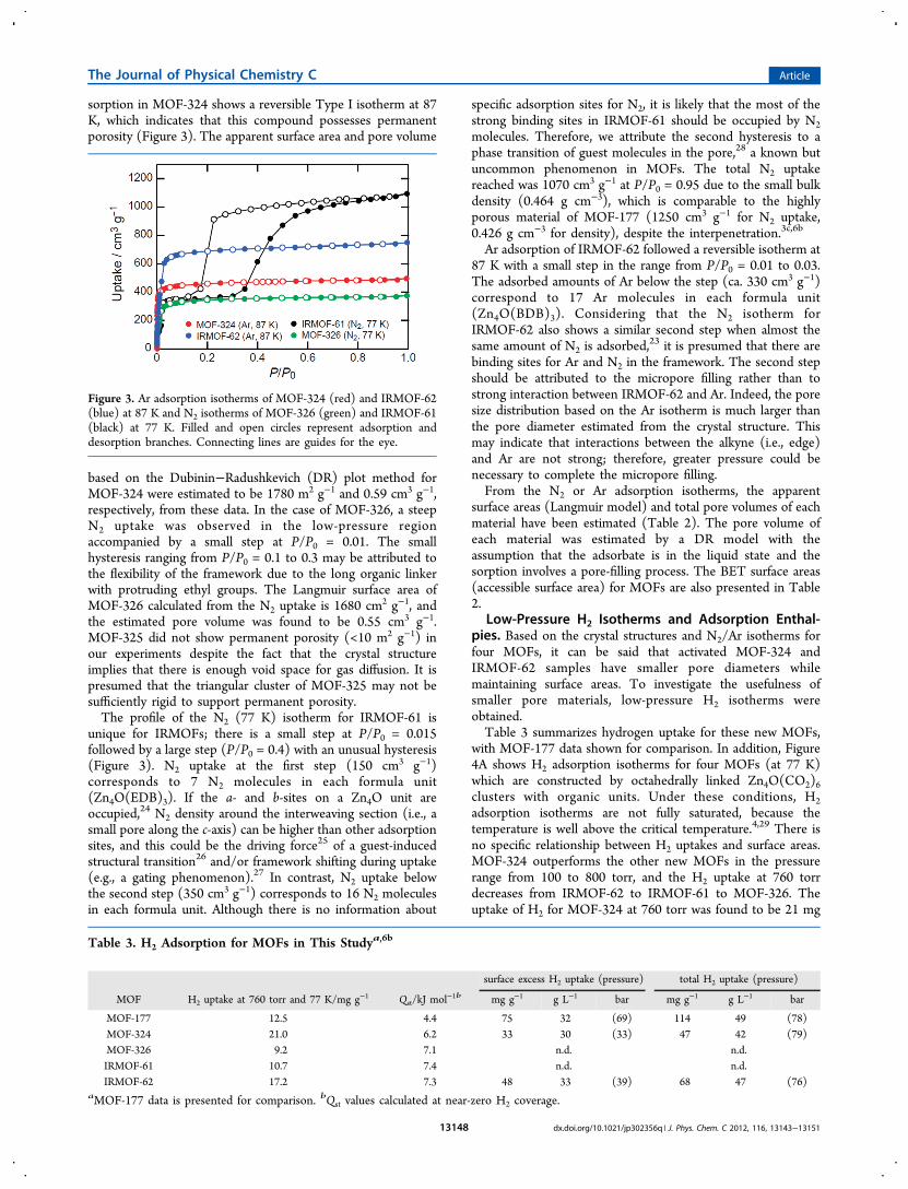
sorption in MOF-324 shows a reversible Type I isotherm at 87K, which indicates that this compound possesses permanentporosity (Figure 3). The apparent surface area and pore volume
based on the Dubinin−Radushkevich (DR) plot method forMOF-324 were estimated to be 1780 m2 g−1 and 0.59 cm3 g−1,respectively, from these data. In the case of MOF-326, a steepN2 uptake was observed in the low-pressure regionaccompanied by a small step at P/P0 = 0.01. The smallhysteresis ranging from P/P0 = 0.1 to 0.3 may be attributed tothe flexibility of the framework due to the long organic linkerwith protruding ethyl groups. The Langmuir surface area ofMOF-326 calculated from the N2 uptake is 1680 cm2 g−1, andthe estimated pore volume was found to be 0.55 cm3 g−1.MOF-325 did not show permanent porosity (<10 m2 g−1) inour experiments despite the fact that the crystal structureimplies that there is enough void space for gas diffusion. It ispresumed that the triangular cluster of MOF-325 may not besufficiently rigid to support permanent porosity.The profile of the N2 (77 K) isotherm for IRMOF-61 is
unique for IRMOFs; there is a small step at P/P0 = 0.015followed by a large step (P/P0 = 0.4) with an unusual hysteresis(Figure 3). N2 uptake at the first step (150 cm3 g−1)corresponds to 7 N2 molecules in each formula unit(Zn4O(EDB)3). If the a- and b-sites on a Zn4O unit areoccupied,24 N2 density around the interweaving section (i.e., asmall pore along the c-axis) can be higher than other adsorptionsites, and this could be the driving force25 of a guest-inducedstructural transition26 and/or framework shifting during uptake(e.g., a gating phenomenon).27 In contrast, N2 uptake belowthe second step (350 cm3 g−1) corresponds to 16 N2 moleculesin each formula unit. Although there is no information about
specific adsorption sites for N2, it is likely that the most of thestrong binding sites in IRMOF-61 should be occupied by N2molecules. Therefore, we attribute the second hysteresis to aphase transition of guest molecules in the pore,28 a known butuncommon phenomenon in MOFs. The total N2 uptakereached was 1070 cm3 g−1 at P/P0 = 0.95 due to the small bulkdensity (0.464 g cm−3), which is comparable to the highlyporous material of MOF-177 (1250 cm3 g−1 for N2 uptake,0.426 g cm−3 for density), despite the interpenetration.3c,6b
Ar adsorption of IRMOF-62 followed a reversible isotherm at87 K with a small step in the range from P/P0 = 0.01 to 0.03.The adsorbed amounts of Ar below the step (ca. 330 cm3 g−1)correspond to 17 Ar molecules in each formula unit(Zn4O(BDB)3). Considering that the N2 isotherm forIRMOF-62 also shows a similar second step when almost thesame amount of N2 is adsorbed,
23 it is presumed that there arebinding sites for Ar and N2 in the framework. The second stepshould be attributed to the micropore filling rather than tostrong interaction between IRMOF-62 and Ar. Indeed, the poresize distribution based on the Ar isotherm is much larger thanthe pore diameter estimated from the crystal structure. Thismay indicate that interactions between the alkyne (i.e., edge)and Ar are not strong; therefore, greater pressure could benecessary to complete the micropore filling.From the N2 or Ar adsorption isotherms, the apparent
surface areas (Langmuir model) and total pore volumes of eachmaterial have been estimated (Table 2). The pore volume ofeach material was estimated by a DR model with theassumption that the adsorbate is in the liquid state and thesorption involves a pore-filling process. The BET surface areas(accessible surface area) for MOFs are also presented in Table2.
Low-Pressure H2 Isotherms and Adsorption Enthal-pies. Based on the crystal structures and N2/Ar isotherms forfour MOFs, it can be said that activated MOF-324 andIRMOF-62 samples have smaller pore diameters whilemaintaining surface areas. To investigate the usefulness ofsmaller pore materials, low-pressure H2 isotherms wereobtained.Table 3 summarizes hydrogen uptake for these new MOFs,
with MOF-177 data shown for comparison. In addition, Figure4A shows H2 adsorption isotherms for four MOFs (at 77 K)which are constructed by octahedrally linked Zn4O(CO2)6clusters with organic units. Under these conditions, H2adsorption isotherms are not fully saturated, because thetemperature is well above the critical temperature.4,29 There isno specific relationship between H2 uptakes and surface areas.MOF-324 outperforms the other new MOFs in the pressurerange from 100 to 800 torr, and the H2 uptake at 760 torrdecreases from IRMOF-62 to IRMOF-61 to MOF-326. Theuptake of H2 for MOF-324 at 760 torr was found to be 21 mg
Figure 3. Ar adsorption isotherms of MOF-324 (red) and IRMOF-62(blue) at 87 K and N2 isotherms of MOF-326 (green) and IRMOF-61(black) at 77 K. Filled and open circles represent adsorption anddesorption branches. Connecting lines are guides for the eye.
Table 3. H2 Adsorption for MOFs in This Studya,6b
surface excess H2 uptake (pressure) total H2 uptake (pressure)
MOF H2 uptake at 760 torr and 77 K/mg g−1 Qst/kJ mol−1b mg g−1 g L−1 bar mg g−1 g L−1 bar
MOF-177 12.5 4.4 75 32 (69) 114 49 (78)MOF-324 21.0 6.2 33 30 (33) 47 42 (79)MOF-326 9.2 7.1 n.d. n.d.IRMOF-61 10.7 7.4 n.d. n.d.IRMOF-62 17.2 7.3 48 33 (39) 68 47 (76)
aMOF-177 data is presented for comparison. bQst values calculated at near-zero H2 coverage.
The Journal of Physical Chemistry C Article
dx.doi.org/10.1021/jp302356q | J. Phys. Chem. C 2012, 116, 13143−1315113148

g−1. This is slightly lower than that in MOF-505 and HKUST-1(24 and 25 mg g−1), materials with open metal sites, but muchhigher than that in MOF-5 and MOF-177 (13 and 12 mg g−1)in this low-pressure region.4,6a,29
To further investigate the interaction between adsorbent andH2 molecules, H2 adsorption isotherms were collected at 77and 87 K for IRMOF-61, IRMOF-62, MOF-324, and MOF-326.23,30 Figure 4B demonstrates the coverage dependencies ofQst calculated from fitting the 77 and 87 K data. IRMOF-61,IRMOF-62, and MOF-326 show near-zero coverage Qst valuesof 7.4, 7.3, and 7.1 kJ mol−1, respectively, which are greater thanthose of MOF-177, MOF-5, and HKUST-1 (4.4, 4.9, and 6.9 kJmol−1) but less than those of MOF-74 and IRMOF-11 (7.9,and 9.1 kJ mol−1).6a,b In the case of MOF-324, the initial Qst(6.2 kJ mol−1) is lower than those of IRMOF-62 and MOF-326. This suggests that pore environments near the Zn4O unitsare more suitable toward H2 binding than the Zn3OH unit inMOF-324 at low coverage. However, it is worth noting that theQst for MOF-324 is not substantially influenced by the surfacecoverage of H2 (5.6 kJ mol−1 at 15 mg g−1 of surface coverage).We attribute this effect to the small pore diameter in MOF-324,which facilitates stronger binding of H2 by interactions withmany more surface sites. This is in sharp contrast to MOF-326,in which the boron and nitrogen atoms in the link arenegatively and positively charged, respectively; MOF-326shows a gradual decrement to 4.5 kJ mol−1 at 7 mg g−1 ofsurface coverage, as the polarized B−N bonds appear toimprove the H2 binding energy with respect to simple aromaticunits seen in previous MOFs. In IRMOF-62, with itscomplicated pore structure, H2 is expected to be adsorbed onthe stronger binding sites (e.g., Zn4O unit31,32) first, followed
by less strong binding in the more open pores of the MOF,which is consistent with the moderate decrement of the Qst. Asimilar initial binding energy is seen for IRMOF-61. Weattribute the near-zero coverage values to stronger binding atthe Zn clusters facilitated by the closeness of clusters due tointerpenetration in each material. At higher coverage, thebinding energy decreases to approximately 5 kJ mol−1 forIRMOF-62 and approximately 6 kJ mol−1 for IRMOF-61. Inboth cases, the binding energies are still greater than that ofMOF-177 at higher coverage, which we hypothesize can beattributed to the alkynes; because IRMOF-61 has much largerpores than IRMOF-62, the best explanation for their respectivebinding energies so far is the fact that they both containcarbon−carbon triple bond units.
High-Pressure H2 Storage. MOF-324 and IRMOF-62were investigated for their high-pressure H2 capacities at 77 and298 K (Figure 5A). The gravimetric excess H2 uptakes at 77 K
for MOF-324 and IRMOF-62 are 33 and 49 mg g−1,respectively. These are only modest gravimetric uptakescompared to 75 mg g−1 for MOF-177 at approximately 70bar, because excess H2 uptake in the high-pressure region issubstantially dependent on the surface area (or microporevolume) of MOF rather than adsorption enthalpy.33,34
Although the surface excess mass is a useful concept, fromthe viewpoint of H2 storage, the total amount that a materialcan store is more relevant to use for H2 as a fuel. Since the totaladsorbed amount cannot be measured experimentally, weestimate the total uptake of H2 using a pore volume of MOFs
Figure 4. (a) Low-pressure H2 isotherms of MOFs at 77 K. Allsymbols are the same as in Figure 3. Connecting lines are guides forthe eye. (b) Coverage dependencies of the isosteric heat of adsorptionfor H2 in MOFs calculated from fits of its 77 and 87 K isotherms.
Figure 5. (a) High-pressure H2 excess uptakes for MOF-324 (red) andIRMOF-62 (blue) in gravimetric unit collected at 77 (circles) and 298K (squares). (b) Surface excess (circles) and total (triangles) H2uptake in MOF-324 (red) and IRMOF-62 (blue) at 77 K areconverted in the volumetric unit. Data for MOF-177 (black brokencurves)6b and the bulk density of H2 at the same temperature (greencurve) are shown for comparison. Filled and open circles representadsorption and desorption branches. Connecting lines are guides forthe eyes.
The Journal of Physical Chemistry C Article
dx.doi.org/10.1021/jp302356q | J. Phys. Chem. C 2012, 116, 13143−1315113149

and bulk H2 density (Ntotal = Nex + ρbulkVp,DR).6b,c Figure 5B
demonstrates the total uptake of H2 in volumetric units (g L−1).By this metric, the MOF materials are much more similar intheir hydrogen uptake capacities.34 Indeed, the total H2 uptakein IRMOF-62 (volumetric units) is even greater than that inMOF-177 up to 60 bar. This clearly demonstrates that highlyinterpenetrating structures do not always have a negativeimpact on the gas storage capacity, but that interpenetration is ahighly useful attribute for obtaining high hydrogen capacity.As shown in Figure 5, MOF-324 and IRMOF-62 show lower
saturation pressures (39 bar) than that for MOF-177, aspredicted from their greater binding energies for H2. Toillustrate their reversible and fast hydrogen uptake (andrelease), a time course profile of adsorption and successivedesorption processes in IRMOF-62 was recorded,23 showingthat adsorption and desorption processes are almost completewithin 5 min even though a large pressure change (2−53 bar) isapplied to the experimental system. This clearly demonstratesthat the interpenetration does not disturb fast gas diffusion inmicropores.Inelastic Neutron-Scattering Study of the Rotational
Transition of Hydrogen Adsorbed in MOF-324. Furtherdetails about the binding of H2 in MOF-324 were derived frominelastic neutron-scattering (INS) experiments.31 The INSspectrum of one, two, and three hydrogen molecules performula unit adsorbed in MOF-324 is shown in Figure 6. The
two most noteworthy aspects of these spectra when comparedto those obtained for MOF-5, for example, are the broadeningof the peaks and the significant amount of intensity found atenergies less than 10 meV. The width of the bands suggests thatthe binding sites are not as well-defined as in MOF-5, mostlikely because the smaller channels subject the hydrogenmolecules to additional interactions, so that it can take up avariety of favorable binding sites. The occurrence of transitionsat lower energy implies the presence of sites with strongerinteractions between hydrogen and host material, which wemay also attribute to the smaller pore sizes. We can identify atleast four different H2 binding sites at the lowest loading, andnote that the intensities of all the peaks associated with thesesites (i.e., their population) increase at similar rates withincreases in H2 loading to two molecules per formula unit. Thisobservation is in accord with the rather weak dependence of Qston H2 coverage described above.In analogy with the primary binding site in MOF-5, we
attribute the peak at the lowest energy, i.e., 6.4 meV, to
hydrogen molecules adsorbed at a site on the metal cluster. Therotational transition frequency for the pocket site on the clusterin MOF-5 is 10.3 meV, which corresponds to a twofold barrierto rotation of 1.8 kJ mol−1 vs 3.7 kJ mol−1 in MOF-324. Themuch stronger interaction in MOF-324 is reflected in the low-coverage heat of adsorption of 6.2 kJ mol−1 compared with 4.8kJ mol−1 in MOF-5. Two other sites with strong interactions ofH2 are found to be occupied at low loadings, whereas at higherloadings the transition energies observed (11−14 meV) reflectthose identified by us for sites near and on the organic linkers.
■ CONCLUSIONSWe have explored the use of new functionalities and resultingpore-size control toward improving hydrogen uptake. WithMOF-324, we demonstrate the usefulness of generating a shortlink in situ to form a MOF with a small pore diameter, whichexhibits excellent cryogenic H2 (77 K) uptake at 760 torr. Thehydrogen uptake in MOF-326 indicates that more polarizablelinks are indeed beneficial toward hydrogen uptake throughimproved interactions with the guests at higher loading.IRMOF-61 and 62 show evidence that long links can be usedto generate highly interpenetrated structures with novel modesof interpenetration, allowing for control of pore dimensionsand density of adsorptive sites that prove advantageous as partof the greater scheme for improving hydrogen uptake in MOFs.More importantly, IRMOF-62 shows volumetric H2 uptakecapacity on par with MOF-177 at high pressures, includingimproved energy of interaction and higher uptake than MOF-177 up to 60 bar, due to the ideal pore diameters for H2storage. The small pore of IRMOF-62 (5.2 Å) has no negativeimpact on fast gas diffusion.
■ ASSOCIATED CONTENT*S Supporting InformationDetails of the single-crystal X-ray data collection and analysisfor five MOFs, powder X-ray diffraction patterns (simulatedand experimental), TGA traces, N2/Ar (semilogarithmic scale)and low-pressure H2 isotherms at 77 and 87 K for MOF-324,326 and IRMOF-61, 62, the time course profile of H2 uptakefor IRMOF-62, synthetic procedures and characterization ofH2EDB and H2BDB, and complete ref 3i. This material isavailable free of charge via the Internet at http://pubs.acs.org.
■ AUTHOR INFORMATIONCorresponding Author*E-mail: [email protected] Address⊥Department of Chemistry, University of California and TheMolecular Foundry at Lawrence Berkeley National Laboratory,Berkeley, CA 94720, United States.NotesThe authors declare no competing financial interest.
■ ACKNOWLEDGMENTSWe are grateful to Dr. J. L. C. Rowsell, Dr. A. P. Cote, and Prof.J. Kim for their help in the single-crystal X-ray structurecollection and analysis and to Prof. M. O’Keeffe for analysis ofthe interpenetration in IRMOF-62. This work was supportedby the Department of Energy (DOE) (DE-FG36-05GO15001)and BASF SE. O.M.Y. is also supported by the WCU (NRF R-31-2008-000-10055-0) program funded by the Ministry ofEducation, Science and Technology, Korea. This work has
Figure 6. INS spectra for one (green), two (blue), and three (red)hydrogen molecules per formula unit adsorbed in MOF-324.
The Journal of Physical Chemistry C Article
dx.doi.org/10.1021/jp302356q | J. Phys. Chem. C 2012, 116, 13143−1315113150

benefited from the use of facilities at the Intense PulsedNeutron Source, a national user facility funded as such by theOffice of Science, U.S. DOE.
■ REFERENCES(1) (a) Satyapal, S.; Petrovic, J.; Read, C.; Thomas, G.; Ordaz, G.Catal. Today 2007, 120, 246−256. (b) IPCC 2007; Climate Change2007: Synthesis Report; Pachauri, R. K., Reisinger, A., Eds.; IPCC:Geneva, Switzerland, 2008.(2) (a) Suh, M. P.; Park, H. J.; Prasad, T. K.; Lim, D.-W. Chem. Rev.2012, 112, 782−835. (b) Ma, S.; Zhou, H.-C. Chem. Commun. 2010,46, 44−53. (c) Murray, L. J.; Dinca, M.; Long, J. R. Chem. Soc. Rev.2009, 38, 1294−1314.(3) (a) Li, H.; Eddaoudi, M.; O’Keeffe, M.; Yaghi, O. M. Nature1999, 402, 276−279. (b) Eddaoudi, M.; Kim, J.; Rosi, N.; Vodak, D.;Wachter, J.; O’Keeffe, M.; Yaghi, O. M. Science 2002, 295, 469−472.(c) Chae, H. K.; Siberio-Perez, D. Y.; Kim, J.; Go, Y.; Eddaoudi, M.;Matzger, A. J.; O’Keeffe, M.; Yaghi, O. M. Nature 2004, 427, 523−527.(d) Chui, S. S.-Y.; Lo, S. M.-F.; Charmant, J. P. H.; Orpen, A. G.;Williams, I. D. Science 1999, 283, 1148−1150. (e) Yan, Y.; Lin, X.;Yang, S.; Blake, A. J.; Dailly, A.; Champness, N. R.; Hubberstey, P.;Schroder, M. Chem. Commun. 2009, 1025−1027. (f) Dinca, M.; Long,J. R. Angew. Chem., Int. Ed. 2008, 47, 6766−6779. (g) Sun, D.; Ma, S.;Ke, Y.; Collins, D. J.; Zhou, H.-C. J. Am. Chem. Soc. 2006, 128, 3896−3897. (h) Ferey, G.; Mellot-Draznieks, C.; Serre, C.; Millange, F.;Dutour, J.; Surble, S.; Margiolaki, I. Science 2005, 309, 2040−2042.(i) Furukawa, H.; et al. Science 2010, 329, 424−428. (j) Klein, N.;Senkovska, I.; Gedrich, K.; Stoeck, U.; Henschel, A.; Mueller, U.;Kaskel, S. Angew. Chem., Int. Ed. 2009, 48, 9954−9957.(4) Chen, B.; Ockwig, N. W.; Millward, A. R.; Contreras, D. S.;Yaghi, O. M. Angew. Chem., Int. Ed. 2005, 44, 4745−4749.(5) (a) Lowell, S.; Shields, J. E.; Thomas, M. A.; Thommes, M.Characterization of Porous Solids and Powders: Surface Area, Pore Sizeand Density, Kluwer Academic Publishers: Dordrecht, The Nether-lands, 2004. (b) Rouquerol, F.; Rouquerol, J.; Sing, K. Adsorption byPowders & Porous Solids; Academic Press: London, U.K., 1999.(6) (a) Rowsell, J. L. C.; Yaghi, O. M. J. Am. Chem. Soc. 2006, 128,1304−1315. (b) Furukawa, H.; Miller, M. A.; Yaghi, O. M. J. Mater.Chem. 2007, 17, 3197−3204. (c) Furukawa, H.; Yaghi, O. M. J. Am.Chem. Soc. 2009, 131, 8875−8883.(7) (a) Trofimenko, S. J. Am. Chem. Soc. 1967, 89, 4948−4952.(b) Trofimenko, S. J. Am. Chem. Soc. 1967, 89, 3165−3170.(c) Trofimenko, S. J. Org. Chem. 1963, 28, 2755−2758.(8) Kraus, W.; Nolze, G. J. Appl. Crystallogr. 1996, 29, 301−303.(9) (a) Goodgame, D. M. L.; Grachvogel, D. A.; Williams, D. J.Angew. Chem., Int. Ed. 1999, 38, 153−156. (b) Tao, J.; Zhang, Y.;Tong, M.-L.; Chen, X.-M.; Yuen, T.; Lin, C. L.; Huang, X.; Li, J. Chem.Commun. 2002, 1342−1343. (c) Xiong, R.-G.; Zhang, J.; Chen, Z.-F.;You, X.-Z.; Che, C.-M.; Fun, H.-K. J. Chem. Soc., Dalton Trans. 2001,780−782. (d) Feller, R. K.; Forster, P. M.; Wudl, F.; Cheetham, A. K.Inorg. Chem. 2007, 46, 8717−8721. (e) Zhao, D.; Yuan, D.;Yakovenko, A.; Zhou, H.-C. Chem. Commun. 2010, 46, 4196−4198.(10) Hafizovic, J.; Bjørgen, M.; Olsbye, U.; Dietzel, P. D. C.; Bordiga,S.; Prestipino, C.; Lamberti, C.; Lillerud, K. P. J. Am. Chem. Soc. 2007,129, 3612−3620.(11) Tranchemontagne, D. J.; Hunt, J. R.; Yaghi, O. M. Tetrahedron2008, 64, 8553−8557.(12) Reineke, T. M.; Eddaoudi, M.; Moler, D.; O’Keeffe, M.; Yaghi,O. M. J. Am. Chem. Soc. 2000, 122, 4843−4844.(13) The three letter designators generally given for importantcommon nets as outlined in Reticular Chemistry Structure Resource(RCSR); http://rcsr.anu.edu.au/: O’Keeffe, M.; Peskov, M. A.;Ramsen, S. J.; Yaghi, O. M. Acc. Chem. Res. 2008, 41, 1782−1789.(14) Katritzky, A. R.; Nichols, D. A.; Siskin, M.; Murugan, R.;Balasubramanian, M. Chem. Rev. 2001, 101, 837−892.(15) Norwood, V. M., III; Morse, K. W. Inorg. Chem. 1987, 26, 284−288.
(16) Procopio, E. Q.; Linares, F.; Montoro, C.; Colombo, V.;Maspero, A.; Barea, E.; Navarro, J. A. R. Angew. Chem., Int. Ed. 2010,49, 7308−7311.(17) (a) Mezei, G.; McGrady, J. E.; Raptis, R. G. Inorg. Chem. 2005,44, 7271−7273. (b) Mezei, G.; Rivera-Carrillo, M.; Raptis, R. G.Dalton Trans. 2007, 37−40.(18) (a) Pham, B. T. N.; Lund, L. M.; Song, D. Inorg. Chem. 2008,47, 6329−6335. (b) Gadzikwa, T.; Zeng, B.-S.; Hupp, J. T.; Nguyen, S.T. Chem. Commun. 2008, 3672−3674.(19) Rowsell, J. L. C.; Yaghi, O. M. Angew. Chem., Int. Ed. 2005, 44,4670−4679.(20) Kesanli, B.; Cui, Y.; Smith, M. R.; Bittner, E. W.; Bockrath, B.C.; Lin, W. Angew. Chem., Int. Ed. 2005, 44, 72−75.(21) Batten, S. R. CrystEngComm 2001, 18, 1−7.(22) Hong, C. S.; Son, S.-K.; Lee, Y. S.; Jun, M.-J.; Do, Y. Inorg.Chem. 1999, 38, 5602−5610.(23) See Supporting Information for details.(24) Rowsell, J. L. C.; Spencer, E. C.; Eckert, J.; Howard, J. A. K.;Yaghi, O. M. Science 2005, 309, 1350−1354.(25) We do not know how the structural transition of IRMOF-61occurs; however, it should be noted that a small, but unusual,hysteresis loop was also observed for low-pressure H2 isotherms at 77and 87 K (Figure S37). Since H2 is not condensed in the pore underthe present experimental conditions, no phase transition of H2 in thepore should be observed. Therefore, the hysteresis loop of the H2isotherms should be attributed to the framework−guest interaction,where part of the heat of H2 adsorption was used for the structuraltransition. The heat of H2 adsorption is generally smaller than that ofN2 so that it should be easy to gain enough energy to cause thestructural transition by the adsorption of N2.(26) (a) Kitaura, R.; Fujimoto, K.; Noro, S.; Kondo, M.; Kitagawa, S.Angew. Chem., Int. Ed. 2002, 41, 133−135. (b) Cussen, E. J.; Claridge,J. B.; Rosseinsky, M. J.; Kepert, C. J. J. Am. Chem. Soc. 2002, 124,9574−9581. (c) Tanaka, D.; Nakagawa, K.; Higuchi, M.; Horike, S.;Kubota, Y.; Kobayashi, T. C.; Takata, M.; Kitagawa, S. Angew. Chem.,Int. Ed. 2008, 47, 3914−3918. (d) Coudert, F.-X.; Jeffroy, M.; Fuchs,A. H.; Boutin, A.; Mellot-Draznieks, C. J. Am. Chem. Soc. 2008, 130,14294−14302.(27) (a) Kitaura, R.; Seki, K.; Akiyama, G.; Kitagawa, S. Angew.Chem., Int. Ed. 2003, 42, 428−431. (b) Kondo, A.; Noguchi, H.;Carlucci, L.; Proserpio, D. M.; Ciani, G.; Kajiro, H.; Ohba, T.; Kanoh,H.; Kaneko, K. J. Am. Chem. Soc. 2007, 129, 12362−12363. (c) Chen,B.; Liang, C.; Yang, J.; Contreras, D. S.; Clancy, Y. L.; Lobkovsky, E.B.; Yaghi, O. M.; Dai, S. Angew. Chem., Int. Ed. 2006, 45, 1390−1393.(28) (a) Lincke, J.; Lassig, D.; Moellmer, J.; Reichenbach, C.; Puls,A.; Moeller, A.; Glaser, R.; Kalies, G.; Staudt, R.; Krautscheid, H.Microporous Mesoporous Mater. 2011, 142, 62−69. (b) Reichenbach,C.; Kalies, G.; Lincke, J.; Lassig, D.; Krautscheid, H.; Moellmer, J.;Thommes, M. Microporous Mesoporous Mater. 2011, 142, 592−600.(29) Rowsell, J. L. C.; Millward, A. R.; Park, K. S.; Yaghi, O. M. J. Am.Chem. Soc. 2004, 126, 5666−5667.(30) (a) Czepirski, L.; Jagiello, J. Chem. Eng. Sci. 1989, 44, 797−801.(b) Jagiello, J.; Bandosz, T. J.; Putyera, K.; Schwarz, J. A. J. Chem. Eng.Data 1995, 40, 1288−1292.(31) (a) Rowsell, J. L. C.; Eckert, J.; Yaghi, O. M. J. Am. Chem. Soc.2005, 127, 14904−14910. (b) Rosi, N. L.; Eckert, J.; Eddaoudi, M.;Vodak, D. T.; Kim, J.; O’Keeffe, M.; Yaghi, O. M. Science 2003, 300,1127−1129.(32) Spencer, E. C.; Howard, J. A. K.; McIntyre, G. J.; Rowsell, J. L.C.; Yaghi, O. M. Chem. Commun. 2006, 278−280.(33) Wong-Foy, A. G.; Matzger, A. J.; Yaghi, O. M. J. Am. Chem. Soc.2006, 128, 3494−3495.(34) Frost, H.; Duren, T.; Snurr, R. Q. J. Phys. Chem. B 2006, 110,9565−9570.
The Journal of Physical Chemistry C Article
dx.doi.org/10.1021/jp302356q | J. Phys. Chem. C 2012, 116, 13143−1315113151