Hydrogen Generation from Biomass-Derived Carbohydrates via ... · Carbohydrates via the...
25
1 2005 DOE Hydrogen Program Review Arlington, Virginia Hydrogen Generation from Biomass-Derived Carbohydrates via the Aqueous-Phase Reforming (APR) Process Hydrogen Generation from Biomass-Derived Carbohydrates via the Aqueous-Phase Reforming (APR) Process Randy D. Cortright, Ph.D. Virent Energy Systems, Inc. 3571 Anderson Street Madison, WI 53704 www.virent.com May 23, 2005 This Presentation does not contain any proprietary or confidential information Project ID# PD7
-
Upload
dangnguyet -
Category
Documents
-
view
218 -
download
0
Transcript of Hydrogen Generation from Biomass-Derived Carbohydrates via ... · Carbohydrates via the...

1
2005 DOE Hydrogen Program ReviewArlington, Virginia
Hydrogen Generation from Biomass-Derived Carbohydrates via the Aqueous-Phase
Reforming (APR) Process
Hydrogen Generation from Biomass-Derived Carbohydrates via the Aqueous-Phase
Reforming (APR) Process
Randy D. Cortright, Ph.D.Virent Energy Systems, Inc.
3571 Anderson StreetMadison, WI 53704
www.virent.com
May 23, 2005
This Presentation does not contain any proprietary or confidential information
Project ID# PD7

2
OverviewOverviewBarriersProject Timeline
• Barriers addressedCost Reduction of Distributed Hydrogen Generation from Renewable LiquidsBy 2015, reduce cost to $2.50/gge
• Start Date - September 2005
• End Date - August 2008
Budget• Virent Energy Systems
Project Lead – Catalyst/Reactor• Archer Daniel Midland
Feedstock/Demonstration Unit Location
• UOP LLCSystems Engineering
• University of WisconsinFundamental Studies
Partners• Total project funding $2.62 M
DOE share $1.94 MContractor share $0.68 M
• Funding for FY05 None to Date

First Year ObjectivesFirst Year Objectives• Identify candidate sugar streams (Glucose), document plant integration
requirements and associated economic factors.
• Develop catalyst and reactor based on the Aqueous Phase Reforming (APR) process suitable for converting candidate sugar streams tohydrogen.
• Design a baseline hydrogen generation system utilizing the APR process.
• Calculate the thermal efficiency and economics of the baseline APR system.
• Assess the baseline APR system with respect to US Hydrogen program goals and make a go/no go decision to proceed with further development of a demonstration system.
3

4
Second and Third Year ObjectivesSecond and Third Year Objectives
• Develop the detail design of the demonstration APR hydrogen generator system (50 kg/day).
• Fabrication of the integrated hydrogen generator system.
• Install and operate the APR hydrogen generator system at a sugar facility owned by ADM.
• Assess APR hydrogen generator system performance with respect to US Hydrogen program goals.

5
ApproachAqueous Phase Reforming (APR)
ApproachAqueous Phase Reforming (APR)
Ethylene Glycol (AntiFreeze)
Glycerol from Biodiesel
Sorbitol from Glucose or Sucrose sugar
Glucose from Corn
Sugars and Sugar Alcohols from hemi-cellulose
Alkanes
H2/Alkane Mix
Pure H2
Virent
APR

6
Reforming ThermodynamicsReforming Thermodynamics
⇒ Equilibrium is favorable for reforming of oxygenated compounds at low temperatures.
-20
-15
-10
-5
0
5
10
15
20
300 400 500 600 700 800 900 1000Temperature (K)
CH4 : C
6H
14
CH3(OH) : C
6H
8(OH)
6
WGS
ln(P)
Reforming of Hydrocarbons
Water-Gas ShiftReforming of Oxygenated Compounds
CnH2n+2 + nH2O ↔ nCO + (2n+1)H2
CO + H2O ↔ CO2 + H2
CnH2yOn ↔ nCO + yH2

7
Aqueous-phase Reforming of 1 wt% Methanol, Ethylene Glycol, Glycerol, Sorbitol & GlucoseAqueous-phase Reforming of 1 wt% Methanol, Ethylene Glycol, Glycerol, Sorbitol & Glucose
0
20
40
60
80
100
Methanol Ethylene Glycol Glycerol Sorbitol Glucose
H2 Selectivities
Alkane Selectivities
538 K
538 K
498 K
498 K
[Cortright, Davda, and Dumesic, Nature, Volume 418, page 964 (2002)]

8
Reaction PathwaysReaction Pathways
C CO OH H
H H ][n
C COH x
Hx O
* *
H2
H2
H2O
C COH x
Hx O
* * * *
C CHH
* *
C-Ccleavage
alkanes
H2 CO,H2
H2O
H2OWGS
CO2,H2

9
APR Processing of SorbitolAPR Processing of Sorbitol
Utilizes a Single ReactorGeneration of High Pressure HydrogenLow CO Concentrations
Low Temperature Reforming and Water-Gas Shift215 oC over Platinum-Based Catalyst
Liquid-Phase System Total Pressure 310 psia
Aqueous Stream
193 psi H2115 psi CO2
1.4 psi Hydrocarbons0.2 psi H2O
Less than 100 ppm CO
CO + H2O ↔ CO2 + H2
CnH2yOn ↔ nCO + yH2 PhaseSeparator
10
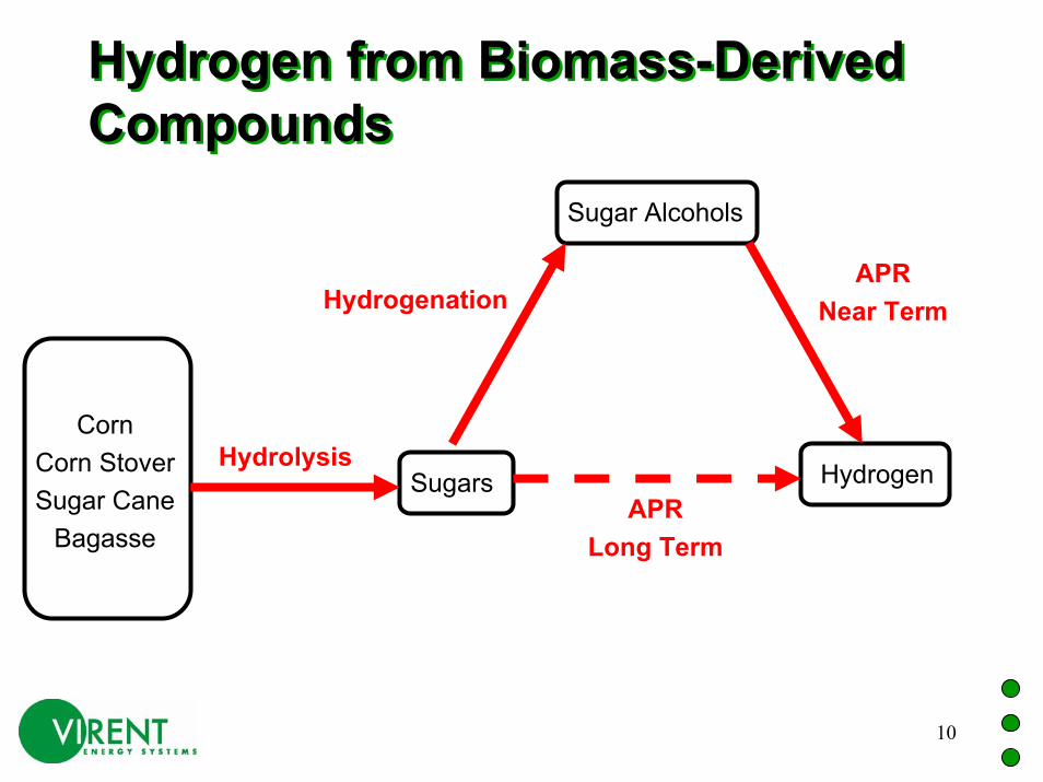
Hydrogen from Biomass-Derived CompoundsHydrogen from Biomass-Derived Compounds
CornCorn StoverSugar Cane
Bagasse
Sugars
Sugar Alcohols
Hydrogen
HydrogenationAPR
Near Term
Hydrolysis
APRLong Term

11
Catalyst Lifetime StudyCatalyst Lifetime Study
0.00
0.50
1.00
1.50
2.00
2.50
0 500 1000 1500
Hours on Stream
Wat
ts H
2 per
gra
m o
f cat
alys
t
Results from NSF STTR Phase I Project
Platinum-Based Catalyst10% Glycerol Feed
Two Month Run from September 2003 to November
2003

12
Catalyst Activity StudiesCatalyst Activity Studies
0
2
4
6
8
10
12
14
16
18
20
Aug-03 Oct-03 Nov-03 Jan-04 Mar-04 Apr-04 Jun-04 Aug-04
Wat
ts H
2 per
gra
m o
f Cat
alys
t
Reported Results of ATP Project
ATP Goal
ATP Funded Project
Increased Activity due to Catalyst Composition, Reactor Design, and
Reaction Conditions
Ethylene Glycol Feed
70 vol% H2 in reactor Effluent

13
Precious Metals CatalystPrecious Metals Catalyst
0.00 2.00 4.00 6.00 8.00 10.00 12.00
Watts/g Catalyst
1.0 Pt
Modified Pt "A"
Modified Pt "B"
Virent "A"
Virent "B"
Cat
alys
t
Catalyst Testing Progress February to June 2004Standard Testing Conditions
Alkane 0.07 0.13 0.09 3.87 5.12
Hydrogen 0.42 1.17 1.16 3.00 6.61
1.0 Pt Modified Pt "A" Modified Pt "B" Virent "A" Virent "B"
6/11/2004
5/21/2004
4/14/2004
3/2/2004
2/24/2004
14
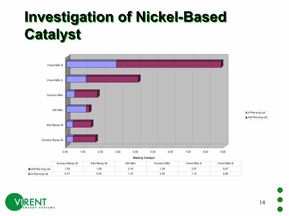
Investigation of Nickel-Based CatalystInvestigation of Nickel-Based Catalyst
0.00 1.00 2.00 3.00 4.00 5.00 6.00 7.00 8.00 9.00
Watts /g Catalys t
Ovonics Raney Ni
Alfa Raney Ni
UW NiSn
Ovonics NiSn
Virent NiSn A
Virent NiSn B
H Pow er/g cat
A lk Pow er/g cat
Alk Pow er/g cat 1.28 1.06 0.19 1.29 2.97 5.97
H Pow er/g cat 0.37 0.34 1.10 0.46 1.12 2.84
Ovonics Raney Ni A lfa Raney Ni UW NiSn Ovonics NiSn Virent NiSn A Virent NiSn B

15
Hydrogen from SorbitolHydrogen from SorbitolPurifierPurified CO2
Purified H2
Waste H
2H
2 0, CO
2Alk an esA
ir
APR Reactor
Reactor Heater
H20CO2N2
Exchanger Gas
Liquid
Water Separator
H2, CO2, Alkanes, H2O
Mixer
LiquidFeed
Feed Pump
Sor
bito
lIn
Wat
er
Sorbitol Water

16
APR Catalytic Reactor ImprovementsAPR Catalytic Reactor ImprovementsPerformance at 100 % Conversion
0
0.2
0.4
0.6
0.8
1
1.2
1.4
Feb-02 Sep-02 Mar-03 Oct-03 Apr-04 Nov-04 May-05
Time
WH
SV (k
g of
Oxy
gena
ted
Com
poun
d/kg
of c
atal
yst h
)
UW Results1% EG
1% SorbitolWHSV 0.008 /h
10 % EG
30 % EG
30 % Sorbitol
30 % Sorbitol
17
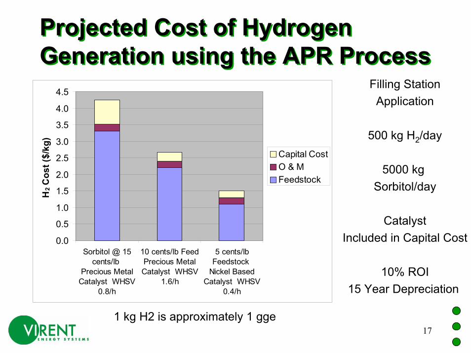
Projected Cost of Hydrogen Generation using the APR ProcessProjected Cost of Hydrogen Generation using the APR Process
Filling StationApplication
500 kg H2/day
5000 kg Sorbitol/day
CatalystIncluded in Capital Cost
10% ROI15 Year Depreciation
0.0
0.5
1.0
1.5
2.0
2.5
3.0
3.5
4.0
4.5
Sorbitol @ 15cents/lb
Precious MetalCatalyst WHSV
0.8/h
10 cents/lb FeedPrecious MetalCatalyst WHSV
1.6/h
5 cents/lbFeedstock
Nickel BasedCatalyst WHSV
0.4/h
H2 C
ost (
$/kg
)
Capital CostO & MFeedstock
1 kg H2 is approximately 1 gge

18
Future Work - First Year TimelineFuture Work - First Year TimelineSEPT OCT NOV DEC JAN FEB MAR APR MAY JUNE JULY AUG
Glucose Sampling
(ADM)
Catalyst and Reactor Testing(Virent)
Fundamental Studies and Catalyst Characterization(University of Wisconsin)
10 kg/day Reactor(Virent)
50 kg/day Unit Design(Virent/UOP)
Go/No GoFor Glucose

19
Future Work - Overall Project TimelineFuture Work - Overall Project Timeline
3rd Q2005
4th Q2005
1st Q2006
2nd Q2006
3rd Q2006
4th Q2006
1st Q2007
2nd Q2007
3rd Q2007
4th Q2007
1st Q2008
2nd Q2008
Go/No GoFor Glucose
Catalyst and Reactor Testing with Glucose
(Virent/UW)
Design, Fabrication, and Deliveryof 50 kg/day Unit
(Virent/UOP)
Operation of 50 kg/day Unit(ADM/Virent/UOP)
Delivery of50 kg/day Unit
20
FacilitiesFacilities• 6500 square feet facility in Madison,
Wisconsin• 14 Technical Personnel• 9 test stands available• Catalyst Preparation Equipment• 3 GC, 1 TOC, 1 GCMS, and analytical
backup from ADM• Fully-equipped machine shop
Experienced machinist for prototype production

21
Virent Laboratory Hydrogen Safety SystemVirent Laboratory Hydrogen Safety System• Hydrogen Exhaust System
Two inch SS tube running North to South in lab.Blower is rated at 17000 L/min.
All Test Stand Vent into this system.• Lab Hydrogen Monitor• Master Permit Relay
Permits test stands to operate unless Hydrogen Exhaust System or Lab Hydrogen Monitor are in alarm state.

22
Supplemental InformationSupplemental Information
• Next Slides Contain Requested Supplemental Information
23
Publications and PresentationsPublications and Presentations
• None to Date
24
Hydrogen SafetyHydrogen Safety
The most significant hydrogen hazard associated with this project would be would be accumulation of a significant amount of hydrogen in the laboratory, for example near the ceiling. The impact to personnel, and/or destruction or loss of equipment or facilities could be devastating if that accumulation reached or exceeded the lower explosion limit (LEL) of 4% and subsequently did explode.
25
Hydrogen SafetyHydrogen Safety
• Our approach to deal with this hazard is:
Limited Hydrogen InventoryHydrogen Exhaust SystemLaboratory VentilationHydrogen MonitorSafety Interlocks


![Presentasi NISN [SLIDE SHARE]](https://static.fdocuments.net/doc/165x107/5592144c1a28abfd628b470c/presentasi-nisn-slide-share.jpg)