Hydrogen from Biomass for Urban Transportation · Hydrogen from Biomass for Urban Transportation Y....
20
Hydrogen from Biomass for Urban Transportation Y. D. Yeboah (PI), K. B. Bota and Z. Wang Clark Atlanta University, Atlanta, GA 30314 Email: [email protected] ; Phone: 404-880-6619 M. Realff Georgia Institute of Technology, Atlanta, GA D. Day and J. Howard Scientific Carbons Inc, Blakely,GA D. McGee Enviro-Tech Enterprises Inc, Matthews, NC and R. Evans, E. Chornet, S. Czernik, C. Feik, R. French, S. Phillips and J. Patrick National Renewable Energy Lab, Golden, CO INTRODUCTION Hydrogen is the most environmentally friendly fuel and can be efficiently used for stationary power and mobile applications. When burned or oxidized, it generates water as the only emission (small amounts of NOx are generated during the combustion process but can be controlled to very low levels). At present, hydrogen is produced almost entirely from fossil fuels such as natural gas, naphtha, and coal. During these hydrogen production processes, large amounts of fossil-derived CO 2 are released to the atmosphere. Renewable biomass is an attractive alternative to fossil feedstocks because of essentially zero net CO 2 impact [1]. Biomass is defined as a material that has participated in the “growing cycle.” Agriculture waste, forest residue, urban wood waste, and trees and grasses grown as energy crops are materials commonly referred to as biomass. Because biomass consumes as much CO 2 in the growing cycle as is produced when it is transformed into energy, the net CO 2 contribution from biomass- derived fuels is considerably less than from fossil-derived fuels. In addition, producing biomass on a sustainable basis by growing energy crops will support the agricultural sector of states 1 Proceedings of the 2002 U.S. DOE Hydrogen Program Review NREL/CP-610-32405
-
Upload
trankhuong -
Category
Documents
-
view
215 -
download
0
Transcript of Hydrogen from Biomass for Urban Transportation · Hydrogen from Biomass for Urban Transportation Y....
Hydrogen from Biomass for Urban Transportation
Y. D. Yeboah (PI), K. B. Bota and Z. Wang Clark Atlanta University, Atlanta, GA 30314
Email: [email protected]; Phone: 404-880-6619
M. Realff Georgia Institute of Technology, Atlanta, GA
D. Day and J. Howard
Scientific Carbons Inc, Blakely,GA
D. McGee Enviro-Tech Enterprises Inc, Matthews, NC
and
R. Evans, E. Chornet, S. Czernik, C. Feik, R. French, S. Phillips and J. Patrick
National Renewable Energy Lab, Golden, CO
INTRODUCTION Hydrogen is the most environmentally friendly fuel and can be efficiently used for stationary power and mobile applications. When burned or oxidized, it generates water as the only emission (small amounts of NOx are generated during the combustion process but can be controlled to very low levels). At present, hydrogen is produced almost entirely from fossil fuels such as natural gas, naphtha, and coal. During these hydrogen production processes, large amounts of fossil-derived CO2 are released to the atmosphere. Renewable biomass is an attractive alternative to fossil feedstocks because of essentially zero net CO2 impact [1]. Biomass is defined as a material that has participated in the “growing cycle.” Agriculture waste, forest residue, urban wood waste, and trees and grasses grown as energy crops are materials commonly referred to as biomass. Because biomass consumes as much CO2 in the growing cycle as is produced when it is transformed into energy, the net CO2 contribution from biomass-derived fuels is considerably less than from fossil-derived fuels. In addition, producing biomass on a sustainable basis by growing energy crops will support the agricultural sector of states
1
Proceedings of the 2002 U.S. DOE Hydrogen Program Review NREL/CP-610-32405
such as Georgia. Successful use of biomass to generate hydrogen for transportation will also reduce oil and gas imports of the U.S. [1]. Agriculture is Georgia’s largest industry and contributes over $46 billion to the state’s annual economic output. One in six Georgians work in an agriculture-related sector. Georgia ranks as the number one state in the U.S. in peanut production, producing about 45% of all peanuts grown in the U.S. Georgia farmers grow about 1.5 billion pounds of peanut in 79 counties annually. Disposal of the large quantity of peanut shells in an environmentally acceptable manner is a significant challenge for the peanut industry. Hence, peanut shells have been targeted as the biomass feedstock for conversion to hydrogen for urban transportation in this project. The National Renewable Energy Laboratory (NREL) in Golden, CO has developed the basis of a technology for the generation of hydrogen from biomass and agricultural residue [2,3]. Biomass can be converted to hydrogen by two distinct strategies: 1) gasification followed by shift conversion and 2) pyrolysis of biomass to form a bio-oil that can be subsequently converted to hydrogen via catalytic steam reforming and shift conversion. The NREL technology uses the latter approach, which has the potential to be cost competitive with current commercial processes for hydrogen production [4]. The process has been demonstrated at the bench scale using model compounds and the carbohydrate-derived fraction of bio-oil [2,3]. This concept has several advantages over the traditional gasification technology. Bio-oil is easily transportable so the second step (steam reforming) can be carried out at a different location, close to the existing infrastructure for hydrogen use or distribution. The second advantage is the potential for production and recovery of higher-value co-products from bio-oil that could significantly impact the economics of the entire process. The hydrogen content in biomass is relatively low (6-6.5%), compared to almost 25% in natural gas. For this reason, producing hydrogen via the biomass gasification/water-gas shift process cannot compete on a cost basis with the well-developed commercial technology for steam reforming of natural gas. However, an integrated process, in which part of the biomass is used to produce more valuable materials or chemicals and the residual fractions are used to generate hydrogen, can be an economically viable option. In the previous NREL work, it was demonstrated, initially through micro-scale tests then in the bench-scale fixed-bed reactor experiments [2, 5, 6], that bio-oil model compounds as well as the carbohydrate-derived fraction of bio-oil can be efficiently converted to hydrogen. Using commercial nickel catalysts the hydrogen yields obtained exceeded 90% of the possible stoichiometric conversion. The carbohydrate-derived bio-oil fraction contains a substantial amount of non-volatile compounds (sugars, oligomers), which tend to decompose thermally and carbonize before contacting the steam reforming catalyst. The prior studies managed to reduce these undesired reactions by injecting the oil fraction to the reactor in a form of a fine mist. However, the carbonaceous deposits on the catalyst and in the reactor freeboard made most of the catalyst inaccessible to contact with the oil limiting the reforming time to 3-4 hours. For the above reasons, NREL decided to employ a different reactor configuration, a fluidized bed, to overcome at least some limitations of the fixed-bed unit. This greatly increased the reforming efficiency and extended the catalyst time-on-stream. Catalyst regeneration was done by steam or carbon dioxide gasification of carbonaceous residues providing additional amounts of hydrogen. Details of the fluidized-bed experiments at NREL with pelletized peanut shells from Scientific Carbons Inc. in Blakely, Georgia, which proved to be encouraging may be found elsewhere [2,3,5,6].
2
Proceedings of the 2002 U.S. DOE Hydrogen Program Review NREL/CP-610-32405

The economics of the proposed approach was assessed with an adhesive coproduct and the selling price of hydrogen was determined to be in the range of $6-8/MBTU [4]. Capital costs were scaled from Mann [4] using a 0.84 exponent. This exponent was derived from the three cases presented in Mann [4]. Fixed operating costs and working capital were also based on the paper. Variable operating costs were determined from the material balance. The pyrolysis vapor was assumed to be available at $2.56/GJ, a value that is roughly 90% of its fuel value (assuming an energy equivalence to natural gas at $2.50/GJ). The analysis also assumed that steam would be produced in the reforming operation. A credit based on $3.50/1000 lbs of steam was assumed. Using the above assumptions, the total capital investment for the additional equipment to modify the existing facility to produce hydrogen from the pyrolysis off-gas was estimated at $1.4 million. For an annual hydrogen production rate of 4.4 million Nm3, the selling price of hydrogen was estimated to be $9.51/GJ. The hydrogen-selling price for a fuel cost of $1.28/GJ (i.e., 45% fuel value) was $7.78/GJ. Using a no-cost bio-oil the selling price for the hydrogen was predicted as $6.05/GJ. These price ranges are very promising considering that the economics were performed for a very small-scale operation. Based on the potential technical and economic advantages of the process, Phase 1 of the project focused on undertaking the engineering research and development studies that would lead to the long term testing of the catalyst and process. PROGRAM GOALS AND OBJECTIVES This project, which is in the Phase 2 stage, focuses on the use of agricultural residues such as peanut shells to produce hydrogen for urban transportation. Specifically, a pilot-scale reactor on site at Scientific Carbons Inc., a small company in Blakely, Southwest Georgia, that produces activated carbon by pyrolysis of densified peanut shells, is being used to test the concept. The primary focus of Phase 1 of the project was to undertake process development studies in the use of the large quantities of peanut shells produced in Georgia as feedstock for the proposed pyrolysis-steam reforming process. The method combines two stages: slow pyrolysis of biomass to generate charcoal and catalytic steam reforming of the pyrolysis vapors to hydrogen and carbon dioxide. Scientific Carbons Inc. is currently operating a commercial facility in Blakely, GA, to convert 24 tons/day of pelletized peanut shells to activated carbon. Scientific Carbons’ pilot-scale reactor, which has a feed rate of 50 kg/hour is being used in the Phase 2 of the project to perform a demonstration of a steam reforming process to convert the off-gas of the peanut-shell carbonization process to hydrogen. As a small company with the demonstrated ability to build modular systems, their current process could be modified and expanded to run a variety of other feedstocks and to make a range of alternative products. In Phase 1 we focused on development of decision models for selecting feedstock, process and alternatives, and designed and managed the construction of a 10-20 kg/hr fluidized-bed catalytic steam reformer system. The catalytic reactor system was successfully constructed and tested at NREL during Phase 1. The emphasis in Phase 2 of the project is on the integration of a pilot scale version of the pyrolyzer used for making activated carbon from densified peanut shells at Scientific Carbons Inc in Southwest Georgia with the steam reformer designed and constructed in Phase 1. The major tasks include: the long term catalyst testing of the reformer with the slow pyrolysis by-product vapors; modeling of the feedstock supply, process economics and deployment strategies; coproducts development and experiments; hydrogen storage and utilization; and partnership building and outreach activities. Thus, Phase 2 involves the engineering research
3
Proceedings of the 2002 U.S. DOE Hydrogen Program Review NREL/CP-610-32405

and pilot-scale process development studies in the use of the large quantities of peanut shells produced in Georgia as feedstock for the pyrolysis-steam reforming process to produce hydrogen for urban transportation. The specific Phase 2 project objectives are to: • Develop decision models for selecting feedstock, process and alternatives and measure and
develop solubility and physical properties of the coproducts; • Design, construct and test the pilot scale pyrolyzer at Scientific Carbons Inc.; • Complete the reformer shakedown at NREL’s Thermochemical Users Facility, ship the unit
to Scientific Carbons and integrate it with the pilot scale pyrolyzer and analytical facilities; • Complete shakedown of the pyrolyzer-reformer system and undertake the long term catalyst
activity testing at Scientific Carbons Inc.; • Undertake the design of a separation and storage system for hydrogen and develop
analytical systems for monitoring transportation system performance; • Develop partnerships/collaborations for future transportation demonstration, the use of other
feedstock, and the development of new processes and markets for the coproducts; and • Educate and train students, especially underrepresented minorities, in the subject area. STATUS OF PROGRESS Below is a summary of the progress to date. • Currently developing a model of network of process steps to account for feedstock, location,
process, and the uncertainties in these factors. • Collected bio-oil and determined solubility parameters and physical property estimation
methods of the components of the bio-oil product of peanut shell pyrolysis. • Undertook shakedown runs of the reformer at NREL. Reactor failure during the preliminary
runs in summer 2001 resulted in subsequent repairs and modifications in the reformer system. Testing at NREL has been completed and the unit shipped to Blakely, Georgia.
• Completed the design and construction of a pilot scale (1/8th scale) pyrolyzer similar to the full-scale unit at Scientific Carbons Inc. Integration of the pyrolyzer with the reformer is nearly completed.
• Prepared the catalyst and feed samples for the pyrolyzer-reformer integration and long-term catalyst testing at Scientific Carbons Inc.
• Initiated evaluation of approaches to hydrogen separation and storage including pressure swing adsorption (PSA) and Quantum’s technology for hydrogen storage.
• Acquired additional analytical instruments for determining and monitoring the composition of the pyrolyzer and reformer inlet and output streams.
• Developed partnerships with several institutions and organizations including the Federation of Southern Cooperatives (for feedstock/farmer training in future phases); Albany State University (summer student interns and community acceptability study); Dougherty County, City of Albany and Georgia’s Water Gas & Light Commission (future bus/transportation demonstration).
• Held a two-day project status review meeting of all collaborating project team partners at NREL, Golden, CO on March 6-7, 2002. A one-day project review meeting, attended by all project team members, was also held at Clark Atlanta University on January 30, 2002. All other communications among the project team were by conference calls.
Details on some of the above summary points are provided below.
4
Proceedings of the 2002 U.S. DOE Hydrogen Program Review NREL/CP-610-32405

Task I: Feedstock supply, process economics, and deployment strategies (Modeling, extraction and property estimation)
Literature data and thermodynamic models were employed to evaluate a large number of organic solvents for the extraction of phenol from aqueous bio-oils. Several good solvents were identified and extractions were carried out on bio-oil samples provided by NREL [7]. Criteria used for selecting a good solvent included:
1. Phenol selectivities should be high. Many solvents, such as hexane, benzene, hexene, heptene, and CCl4, were able to satisfy this criterion (large values of β∞
12 in Table 1). 2. The aqueous phase should contain very little phenol, but an appreciable amount of
solvent. Many solvents did not satisfy this criterion (see β∞31 in Table 1). Examples
include hexane, benzene, hexene, heptene, CCl4, propyl ether, the higher molecular weight ketones and acetates.
3. The solvent solubility in water should be appreciable (~2 wt% at room temperature). If the solubility is too low, the aqueous phase would retain an appreciable amount of phenol.
4. The boiling point of the solvent should be < 130o C for eventual ease of separation by distillation.
5. The solvent should exhibit low toxicity and be inexpensive. Solvent selection Based on ternary liquid-liquid equilibria (LLE) data 20 sets of LLE data for systems of the type phenol + water + solvent were obtained from the literature. The solvents included 7 acetates (from ethyl acetate to hexyl acetate), 6 aromatics (benzene, ethylbenzene, propylbenzene, nitrobenzene, aniline, and naphthalene), 2 ketones (acetone and methyl isobutyl ketone, MIBK), and 2 alcohols (methanol and 2-propanol). Solvent selectivities β = (Xphenol/Xwater)solvent / (Xphenol/Xwater)water and distribution coefficients K = (Xphenol) solvent / (Xphenol)water were calculated from tie-line data and representative results are plotted in Figures 1 and 2. Isopropyl acetate (IPA) exhibited the highest values of both β and K, followed by MIBK. Benzene exhibited the lowest values, and is therefore unlikely to be a good solvent for extracting phenol, particularly at low phenol concentrations in the aqueous phase. Both IPA and MIBK were identified as good solvents for extracting phenol. No ternary LLE data were found for systems involving solvents such as halogenated alkanes, ethers, alcohols, or organic acids. Since these solvents are widely used in practical extractions, binary data and thermodynamic models were employed to generate tie-lines in these systems. Based on binary data and models Limiting values of the selectivity β were calculated in 500 solvents using infinite dilution activity coefficients γ∞. In particular, β∞
12 and β∞31 (where subscript 1= phenol, 2= water, and 3= solvent)
were calculated as follows:
β∞12 = 500 × (γ∞
wat)sol / (γ∞phe)sol (1)
β∞31 = 500 / (γ∞
p)sol / (γ∞s)wat (2)
Activity coefficients were obtained from the literature, or calculated from LLE data. In the absence of experimental data, they were predicted using the UNIFAC model.
5
Proceedings of the 2002 U.S. DOE Hydrogen Program Review NREL/CP-610-32405
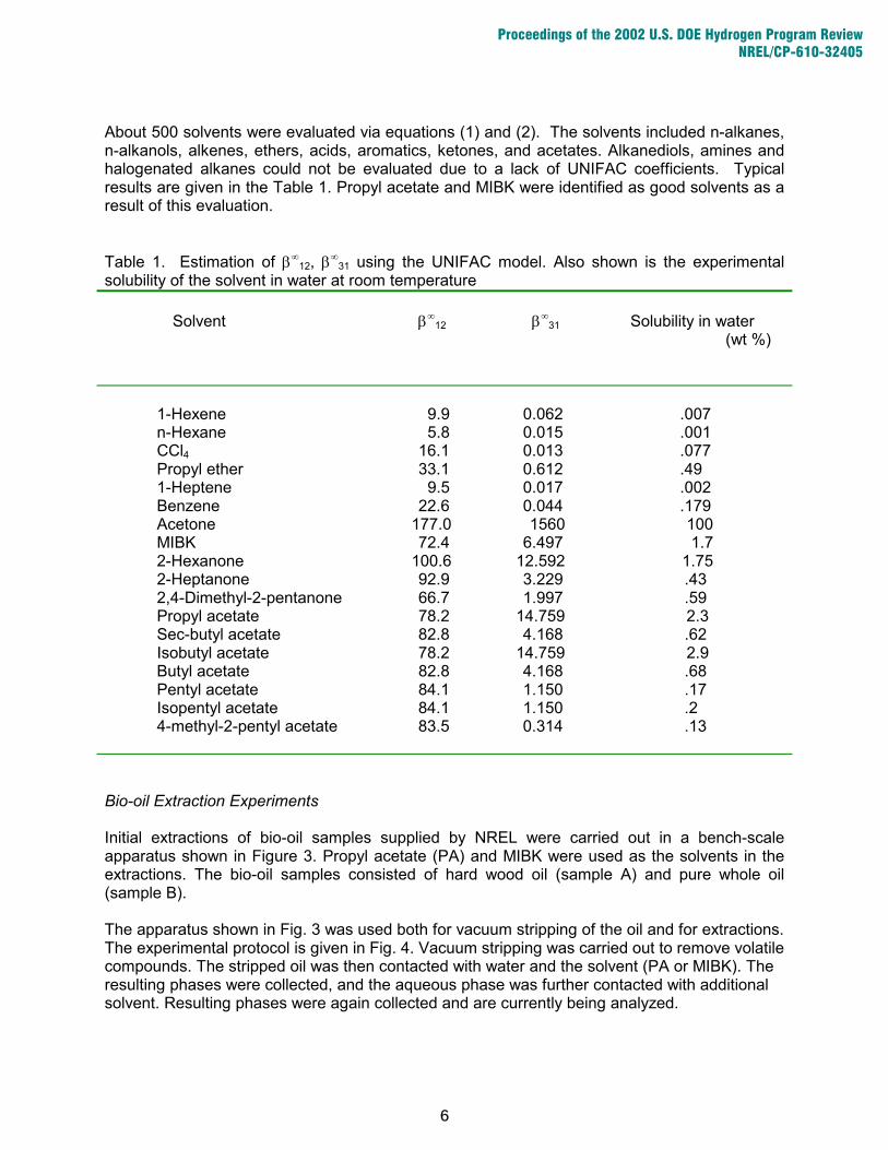
About 500 solvents were evaluated via equations (1) and (2). The solvents included n-alkanes, n-alkanols, alkenes, ethers, acids, aromatics, ketones, and acetates. Alkanediols, amines and halogenated alkanes could not be evaluated due to a lack of UNIFAC coefficients. Typical results are given in the Table 1. Propyl acetate and MIBK were identified as good solvents as a result of this evaluation. Table 1. Estimation of β∞
12, β∞31 using the UNIFAC model. Also shown is the experimental
solubility of the solvent in water at room temperature
Solvent β∞
12 β∞31 Solubility in water
(wt %)
1-Hexene 9.9 0.062 .007 n-Hexane 5.8 0.015 .001 CCl4 16.1 0.013 .077 Propyl ether 33.1 0.612 .49 1-Heptene 9.5 0.017 .002 Benzene 22.6 0.044 .179 Acetone 177.0 1560 100 MIBK 72.4 6.497 1.7 2-Hexanone 100.6 12.592 1.75 2-Heptanone 92.9 3.229 .43 2,4-Dimethyl-2-pentanone 66.7 1.997 .59 Propyl acetate 78.2 14.759 2.3 Sec-butyl acetate 82.8 4.168 .62 Isobutyl acetate 78.2 14.759 2.9 Butyl acetate 82.8 4.168 .68 Pentyl acetate 84.1 1.150 .17 Isopentyl acetate 84.1 1.150 .2 4-methyl-2-pentyl acetate 83.5 0.314 .13
Bio-oil Extraction Experiments Initial extractions of bio-oil samples supplied by NREL were carried out in a bench-scale apparatus shown in Figure 3. Propyl acetate (PA) and MIBK were used as the solvents in the extractions. The bio-oil samples consisted of hard wood oil (sample A) and pure whole oil (sample B). The apparatus shown in Fig. 3 was used both for vacuum stripping of the oil and for extractions. The experimental protocol is given in Fig. 4. Vacuum stripping was carried out to remove volatile compounds. The stripped oil was then contacted with water and the solvent (PA or MIBK). The resulting phases were collected, and the aqueous phase was further contacted with additional solvent. Resulting phases were again collected and are currently being analyzed.
6
Proceedings of the 2002 U.S. DOE Hydrogen Program Review NREL/CP-610-32405

Distribution coefficients
0
20
40
60
0 0.4 0.8 1.2 1.6 2
Phenol mole percent in water phase
K =
(Xph
e)sol /(X
phe)w
at
MIBK
IPA
benzene
Selectivity
2
4
6
8
0 0.4 0.8 1.2 1.6 2
Phenol mole percent in water phase
ln ( β
)=ln
{(
Xph
e/Xw
at)so
l /(Xph
e/Xw
at)w
at}
MIBK
IPA
benzene
Figure 1. Distribution Coefficients of phenol in water and various solvents from tie line data
Figure 2. Solvent selectivities of phenol from tie line data
7
Proceedings of the 2002 U.S. DOE Hydrogen Program Review NREL/CP-610-32405
7 4 1 5 8
3
2
P
6
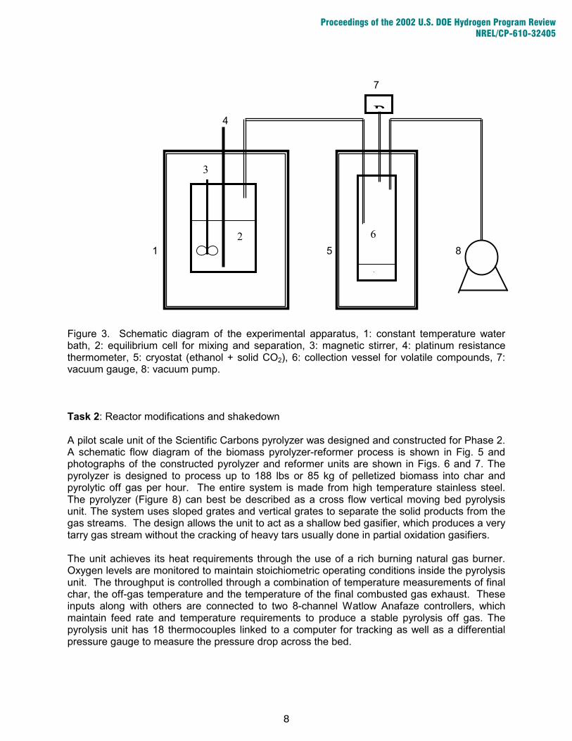
Figure 3. Schematic diagram of the experimental apparatus, 1: constant temperature water bath, 2: equilibrium cell for mixing and separation, 3: magnetic stirrer, 4: platinum resistance thermometer, 5: cryostat (ethanol + solid CO2), 6: collection vessel for volatile compounds, 7: vacuum gauge, 8: vacuum pump.
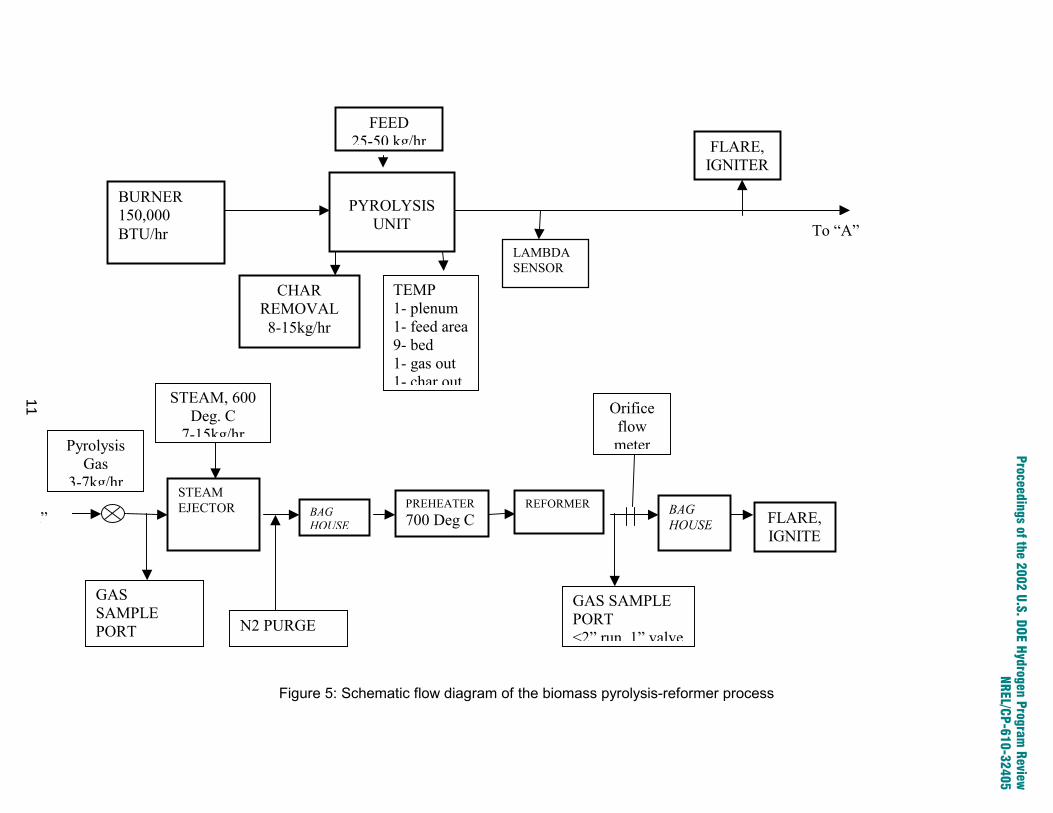
Task 2: Reactor modifications and shakedown A pilot scale unit of the Scientific Carbons pyrolyzer was designed and constructed for Phase 2. A schematic flow diagram of the biomass pyrolyzer-reformer process is shown in Fig. 5 and photographs of the constructed pyrolyzer and reformer units are shown in Figs. 6 and 7. The pyrolyzer is designed to process up to 188 lbs or 85 kg of pelletized biomass into char and pyrolytic off gas per hour. The entire system is made from high temperature stainless steel. The pyrolyzer (Figure 8) can best be described as a cross flow vertical moving bed pyrolysis unit. The system uses sloped grates and vertical grates to separate the solid products from the gas streams. The design allows the unit to act as a shallow bed gasifier, which produces a very tarry gas stream without the cracking of heavy tars usually done in partial oxidation gasifiers. The unit achieves its heat requirements through the use of a rich burning natural gas burner. Oxygen levels are monitored to maintain stoichiometric operating conditions inside the pyrolysis unit. The throughput is controlled through a combination of temperature measurements of final char, the off-gas temperature and the temperature of the final combusted gas exhaust. These inputs along with others are connected to two 8-channel Watlow Anafaze controllers, which maintain feed rate and temperature requirements to produce a stable pyrolysis off gas. The pyrolysis unit has 18 thermocouples linked to a computer for tracking as well as a differential pressure gauge to measure the pressure drop across the bed.
8
Proceedings of the 2002 U.S. DOE Hydrogen Program Review NREL/CP-610-32405

Crude bio-oil Volatile compounds 1)*
Stripped oil (2) 10 g Stripped oil 20 g Water 10 g MIBK
MIBK phase (3) Water phase (4) Oil phase (11) 10 g 10 g MIBK
MIBK phase (5) Water phase (6) 10 g Stripped oil 20 g Water 10 g PA
PA phase (7) Water phase (8) Oil phase (12) 10 g 10 g PA
PA phase (9) Water phase (10)
Vacuum stripped at 2 mm Hg and room temperature
Mixer and separation
Mixer and separation
Mixer and separation
Mixer and separation
Figure 4. Experimental procedure: 1. Removal of volatile compounds 2. MIBK (methyl isobutyl ketone) and water extraction of the stripped bio-oil 3. PA (propyl acetate) and water extraction of the stripped bio-oil
* Numbers (in brackets) refer to sample number.
9
Proceedings of the 2002 U.S. DOE Hydrogen Program Review NREL/CP-610-32405

The off gas is flared to a continuous pilot burner. A fraction of the off-gas is educted by super heated steam into a ceramic baghouse filter system to remove small carbon particles from the gas stream. This particulate clean gas is then fed to a 12 kW superheater, which takes the combined pyrolysis gas and supersteam up to 700 degrees C. The gas stream is then fed into the bottom of the steam reformer. The hydrogen gas from the steam reformer is routed through a ceramic baghouse to remove any particulate nickel dust prior to flaring. Task 3: Long term catalyst testing The long term catalyst testing is expected to begin in June and be completed in July 2002. Currently the pyrolyzer and reformer are being integrated. As soon as system integration is completed the combined system will be tested prior to the long term catalyst testing. The long term catalyst testing is expected to be completed in July 2002. Task 4: Hydrogen separation, storage and utilization Hydrogen Separation The current effort in hydrogen separation is focusing on the use of pressure swing adsorption (PSA) for the separation of the hydrogen from carbon dioxide and will be reported later. Hydrogen Storage and Utilization Hydrogen, with a high energy density, is an extremely useful fuel that has been the focus of much attention in new vehicle technology. It can be combined with compressed natural gas to enhance and create more energy efficient alternative fuels. The ratio of the energy densities of hydrogen to natural gas to gasoline is 1:0.35:0.33. Therefore, adding H2 to natural gas will raise its energy density and create a more viable transportation fuel. The focus of this task entailed the design of a safe hydrogen-compressed natural gas storage system that is relatively lightweight, easy to refuel and capable of increasing the driving range of urban transit buses. The weight of the desired storage system is mainly governed by the construction materials used for the tank. The refuel ability of the tank is restricted by the time and amount of pressurization required to obtain the desired amount of fuel. And finally, the increased driving range, or propulsion efficiency, of the system is controlled by the amount of fuel available to the engine and the amount of energy contained therein. In addition to these constraints, the overall system is ultimately limited by the temperature, pressure and mixture composition. The correlation between CNG and H2 is made because of the similarities between distribution, refueling and possible onboard storage methods. Current CNG storage systems are designed to withstand moderate pressures of 3,000 to 3,600 pounds per square inch (psi) with the former being the current industry standard. This pressure is determined by the strength of the container material and the properties of the contents. Due mainly to the volatility and corrosive properties of hydrogen, the materials available for hydrogen storage are limited. Common storage cylinders for CNG use relatively strong and heavy metal or plastic cylinders. These tanks are heavy because the cylinder walls have to be quite thick in order to withstand the high pressure of the compressed gas. Gasoline tanks are much lighter due to the minimal pressure exerted on the walls of the tank because it is in the liquid state. For these reasons, compressed natural gas tanks are 6 times and compressed hydrogen tanks are two times heavier than those for gasoline. An average gasoline storage system containing 15 gallons of gasoline weighs approximately 150 pounds.
10
Proceedings of the 2002 U.S. DOE Hydrogen Program Review NREL/CP-610-32405
To “A”
“A”
LAMBDA SENSOR
FLARE, IGNITER
TEMP 1- plenum 1- feed area9- bed 1- gas out 1- char out
CHAR REMOVAL 8-15kg/hr
FEED 25-50 kg/hr
PYROLYSIS
UNIT
BURNER 150,000 BTU/hr
Pyrolysis Gas
3-7kg/hr
BAG HOUSE
N2 PURGE
FLARE, IGNITE
Orifice flow meter
BAG HOUSE
GAS SAMPLE PORT <2” run, 1” valve
GAS SAMPLE PORT
REFORMERPREHEATER700 Deg C
STEAM, 600 Deg. C
7-15kg/hr
STEAM EJECTOR
Figure 5: Schematic flow diagram of the biomass pyrolysis-reformer process
11
Proceedings of the 2002 U.S. DOE Hydrogen Program
Review
NREL/CP-610-32405

12
Proceedings of the 2002 U.S. DOE Hydrogen Program Review NREL/CP-610-32405
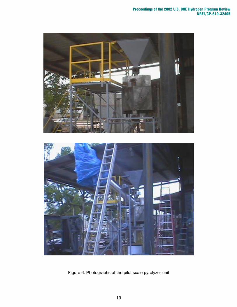
Figure 6: Photographs of the pilot scale pyrolyzer unit
13
Proceedings of the 2002 U.S. DOE Hydrogen Program Review NREL/CP-610-32405

Figure 7: Photographs of the pilot scale reformer and its control panel
14
Proceedings of the 2002 U.S. DOE Hydrogen Program Review NREL/CP-610-32405
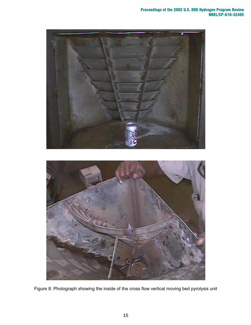
Figure 8: Photograph showing the inside of the cross flow vertical moving bed pyrolysis unit
15
Proceedings of the 2002 U.S. DOE Hydrogen Program Review NREL/CP-610-32405
There are two types of refueling stations available to replenish the gas fuels in vehicles, fast-fill and slow-fill. Fast-fill stations use heavy-duty compressors to compress natural gas in underground storage systems to approximately 3,600 psi. A hose is connected between the storage tank and a refueling port on the vehicle that leads to the onboard storage cylinders. A sensor is attached to the onboard cylinder to monitor the pressure of the gaseous fuel so that the system shuts off and completes the refueling process when a certain value is reached. The time required for fast-fill refueling is only slightly longer than that required for gasoline refueling averaging 10 to 12 minutes.
On the other hand, slow-fill compressed gas refueling uses much smaller compressors to pump the gas directly from the distribution pipelines. Unlike the heavy-duty compressors that pressurize the gas to 3,600 psi, the small compressors only compress the gas to 5 to 15 psi during the transfer from source to vehicle. The sensory and pressurization process for the two refueling techniques are identical. However, the slow-fill compression rate generally amounts to an average of 1 to 3 gallons of compressed gas per hour. This dramatic change in refueling pressure causes the time to change from approximately 10 minutes to overnight for automobiles. Despite the time disadvantage of slow-fill refueling, there are great benefits. The small compressors can achieve the desired results just as the industrial compressors, but at a much lesser cost. The capital and operating costs of the heavy-duty compressors are nearly twice the amount required for the smaller compressors.
Pure hydrogen has corrosive properties and cause the iron alloy and bare steel pipes that carry CNG to become brittle and eventually crack or burst under pressure. In addition to its corrosive properties, hydrogen also has a low ignition temperature, the ability to burn in a wide range of concentrations with air, rapid diffusion and a fast flame speed. These are important safety issues that must be taken into account when designing a storage system for a hydrogen blend.
The most prevalent challenge involved in the design of the H2-CNG utilization system was the identification of the mixture ratio of H2 to CNG. In the United States alone, there are over 1 million miles of CNG pipelines in place. This network of pipelines is vital to the transportation and availability of fuels nationwide. In addition, alteration or replacement of it would be both costly and time consuming. Therefore, one of the present problems is to identify a mixture composition that will provide enough hydrogen to increase the energy efficiency of the fuel, but not damage the piping in which it is enclosed. According to ongoing research, up to 20 percent hydrogen can be added to gas pipelines without allowing the corrosive property of hydrogen to alter the structure of the piping. However, once the mixture is pressurized in a storage cylinder, measures such as a relief valve and inert blanket must be added to ensure safety.
CNG is presently stored in cylinders wrapped in high strength fiberglass or carbon fibers. Materials that are currently in use for gas storage cylinders include pressed steel, wrapped aluminum and composites. The ideal, lightweight cylinder would be composed of exceptionally strong composite materials. The weight constraints on the cylinder are due to the fact that, although gases are extremely light in comparison to liquid fuels, present and past storage systems have been much heavier due to the size and weights of their construction materials. The extra weight of the cylinder adds to the weight of the vehicle thereby decreasing the propulsion efficiency. Another reason that the storage systems need to be constructed from composite materials is because of strength. The walls of the cylinder must be able to withstand high pressures, preferably up to 5000 psi, in order to be filled with a volume of gas fuel that would give a performance comparable to and/or exceeding that of gasoline vehicles. Due to the need for an adiabatic system, the tank must either be insulated or composed of a material that retards heat loss. The high thermal conductivity of aluminum causes temperature differences in
16
Proceedings of the 2002 U.S. DOE Hydrogen Program Review NREL/CP-610-32405
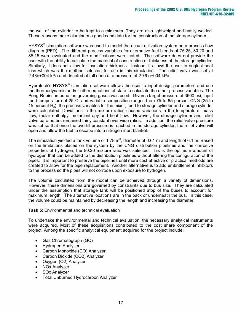
the wall of the cylinder to be kept to a minimum. They are also lightweight and easily welded. These reasons make aluminum a good candidate for the construction of the storage cylinder.
HYSYS© simulation software was used to model the actual utilization system on a process flow diagram (PFD). The different process variables for alternative fuel blends of 75:25, 80:20 and 85:15 were evaluated and the modifications were noted. The software does not provide the user with the ability to calculate the material of construction or thickness of the storage cylinder. Similarly, it does not allow for insulation thickness. Instead, it allows the user to neglect heat loss which was the method selected for use in this simulation. The relief valve was set at 2.48e+004 kPa and denoted at full open at a pressure of 2.76 e+004 kPa.
Hyprotech’s HYSYS© simulation software allows the user to input design parameters and use the thermodynamic and/or other equations of state to calculate the other process variables. The Peng-Robinson equation governing gases was used. Given a target pressure of 3600 psi, input feed temperature of 25°C, and variable composition ranges from 75 to 85 percent CNG (25 to 15 percent H2), the process variables for the mixer, feed to storage cylinder and storage cylinder were calculated. Deviations in the mixture ratios caused variations in the temperature, mass flow, molar enthalpy, molar entropy and heat flow. However, the storage cylinder and relief valve parameters remained fairly constant over wide ratios. In addition, the relief valve pressure was set so that once the overfill pressure is reached in the storage cylinder, the relief valve will open and allow the fuel to escape into a nitrogen inert blanket.
The simulation yielded a tank volume of 1.78 m3, diameter of 0.61 m and length of 6.1 m. Based on the limitations placed on the system by the CNG distribution pipelines and the corrosive properties of hydrogen, the 80:20 mixture ratio was selected. This is the optimum amount of hydrogen that can be added to the distribution pipelines without altering the configuration of the pipes. It is important to preserve the pipelines until more cost effective or practical methods are created to allow for the pipe replacement. Another alternative is to add embrittlement inhibitors to the process so the pipes will not corrode upon exposure to hydrogen. The volume calculated from the model can be achieved through a variety of dimensions. However, these dimensions are governed by constraints due to bus size. They are calculated under the assumption that storage tank will be positioned atop of the buses to account for maximum length. The alternative locations are in the back or underneath the bus. In this case, the volume could be maintained by decreasing the length and increasing the diameter.
Task 5: Environmental and technical evaluation To undertake the environmental and technical evaluation, the necessary analytical instruments were acquired. Most of these acquisitions contributed to the cost share component of the project. Among the specific analytical equipment acquired for the project include:
• Gas Chromatograph (GC) • Hydrogen Analyzer • Carbon Monoxide (CO) Analyzer • Carbon Dioxide (CO2) Analyzer • Oxygen (O2) Analyzer • NOx Analyzer • SOx Analyzer • Total Unburned Hydrocarbon Analyzer
17
Proceedings of the 2002 U.S. DOE Hydrogen Program Review NREL/CP-610-32405
Most of these instruments are being shipped to Scientific Carbons Inc in Blakely, GA for the shakedown and long term testing studies. Task 6: Partnership building and outreach Partnership development with Albany State University, for their role as the community conduit, is underway. An organization meeting was held with Dr. Suren Pandey and Dr. Ellis Sykes, Dean of the ASU Department of Natural Sciences on May 16, 2002. Albany State will collaborate in a community acceptability study. Current plans are to develop and organize a workshop at the university auditorium. This event is designed to provide the community an overview of bioenergy and detail the project progress and benefits expected to be derived from the successful deployment of the validated field test. We are also pursuing the involvement of The Carter Center, based at Emory University in Atlanta. An additional sub-task for ASU is the identification of interested officials at the Albany Technical Institute and the development of workforce strategies for the study of hydrogen and related technologies. ASU has similar arrangements with the Institute and additional strategic areas of training are viewed as a positive initiative for both institutions. The partners will act to develop a university shuttle bus demonstration vehicle and to facilitate the development of local city and county participation as non-operational partners. This role will prepare municipal end-users for the deployment of project results in a timely fashion. University and community representatives will visit the Blakely site and NREL by year-end 2002. The Albany Water, Gas & Light Commission, a municipally owned utility, has continued to show interest in the use of renewable hydrogen for power generation. This interest may lead to the formation of a fuel cell application test in subsequent phases of the project. A meeting to define a fuel cell approach will be held in the July-August timeframe. Prior meetings were held with Dougherty County officials to propose a non-operational role in Phase 3. One ASU student is beginning his second summer on the project. This makes him a valued student, positioned to share his experience with fellow students interested in a technical career. Clark Atlanta had two summer interns working on the project at NREL in the summer of 2001. At least one student will participate in the pilot studies in the summer of 2002 at Blakely, GA. The project team assisted several high school students in Georgia with science projects in the subject area after the project generated significant interest among local high school students from the publication of an article on the project in the Atlanta Journal and Constitution. PROPOSED FUTURE WORK AND MILESTONES Among the key future work and milestones are: • Perform liquid-liquid equilibrium experiments on representative bio-oil compounds and
develop property estimation methods, September 2002 • Develop models and heuristic solution methods for location/process models, September
2002 • Test the pilot scale pyrolyzer at Scientific Carbons Inc., June 2002 • Test all the analytical instruments acquired for the project, June 2002 • Integrate the pyrolyzer, reformer, analytical instruments and accessories, June 2002 • Conduct integrated shakedown and long term catalyst testing at Blakely, GA, July 2002 • Design pressure swing adsorption (PSA) separation and hydrogen storage systems for the
produced hydrogen, September 2002
18
Proceedings of the 2002 U.S. DOE Hydrogen Program Review NREL/CP-610-32405
• Establish additional partnerships to explore the future bus/transportation demonstration option, the use of other feed stocks, and new markets (e.g., adhesives) for the coproducts, September 2002
• Collaborate with Albany State University in a community acceptability study on hydrogen utilization in urban transportation, Fall semester 2002.
• Incorporate hydrogen technology in student training, education and research at Clark Atlanta University, Fall semester 2002
• Submit Phase 3 proposal for continued funding, September 2002. COOPERATIVE EFFORTS • The participating organizations have worked to establish the use of hydrogen from biomass
or agricultural residues and the development of an integrated bioprocessing as major regional thrusts in Georgia and the southeast. Many meetings were held with state and local governments to publicize the project and incorporate the approach in the economic development initiatives for the rural south.
• Developed strategies for partnership building and information dissemination among interested local, regional and national parties.
• Evaluation of an integrated co-products process that utilizes various agricultural residues/feedstocks for enhanced economic benefits is in progress.
• This multifaceted project involving five organizations (Clark Atlanta University, Georgia Tech, Enviro-Tech, Scientific Carbons Inc and the National Renewable Energy Lab) in three states was successfully managed through frequent visits/meetings and conference calls among team members.
• Collaboration and cooperation among the related projects at NREL and the Jet Propulsion Lab to establish the underlying science of the process were established and will be strengthened.
• Two papers were presented and/or published and a third is to be presented at the World Hydrogen Conference in Montreal, Canada.
STUDENT TRAINING AND EDUCATION • Through this project, chemical and mechanical engineering students at Clark Atlanta
University and Albany State University undertake summer research internships at NREL and Scientific Carbons Inc.
• Two students at Clark Atlanta University undertook their senior year design projects on hydrogen separation and storage.
• A senior chemical engineering student at the Georgia Institute of Technology performed process modeling of reformer/water gas shift reactor systems using a process simulation package and engaged in preliminary economic analysis of hydrogen production from peanut shells.
• Several Atlanta metropolitan high school students, after reading about the project in the local newspaper (Atlanta Journal and Constitution), decided to conduct various research projects in the subject area. They were guided in their work by the project team.
REFERENCES
1. The Green Hydrogen Report: The 1995 Progress Report of the Secretary of Energy’s Hydrogen Technical Advisory Panel, May 1995, DOE/GO-10095-179 DE95009213.
19
Proceedings of the 2002 U.S. DOE Hydrogen Program Review NREL/CP-610-32405
2. Wang, D., S. Czernik, D. Montané, M. Mann, and E. Chornet, 1997, I&EC Research, 36, 1507-1518.
3. Wang, D., S. Czernik, and E. Chornet, 1998, “Production of Hydrogen from Biomass by Catalytic Steam Reforming of Fast Pyrolysis Oil”, Energy&Fuels, 12, 19-24.
4. Mann, M.K. 1995. “Technical and economic analyses of hydrogen production via indirectly heated gasification and pyrolysis,” in Proceedings of the 1995 Hydrogen Program Review, Vol. 1, NREL/CP-430-20036-Vol. 1, pp. 205-236.
5. Wang, D., D. Montané, E. Chornet, 1996, “Catalytic Steam Reforming of Biomass-Derived Oxygenates: Acetic Acid and Hydroxyacetaldehyde”, J. Appl. Catal. A: General, 143, 245-270.
6. Czernik, S., D. Wang, D. Montané, E. Chornet, 1997, “Catalytic Steam Reforming of Biomass-Derived Fractions from Pyrolysis Processes. Developments in Thermochemical Biomass Conversion”, Eds. Bridgwater, A.V. and Boocock, D.G.B., Blackie Academic & Professional, pp.672-686.
7. Evans, Robert, National Renewable Energy Lab, Golden, CO, personal communication.
20
Proceedings of the 2002 U.S. DOE Hydrogen Program Review NREL/CP-610-32405