Hydrogen Effect against Hydrogen Embrittlement · Hydrogen Effect against Hydrogen Embrittlement...
15
Hydrogen Effect against Hydrogen Embrittlement YUKITAKA MURAKAMI, TOSHIHIKO KANEZAKI, and YOJI MINE The well-known term ‘‘hydrogen embrittlement’’ (HE) expresses undesirable effects due to hydrogen such as loss of ductility, decreased fracture toughness, and degradation of fatigue properties of metals. However, this article shows, surprisingly, that hydrogen can have an effect against HE. A dramatic phenomenon was found in which charging a supersaturated level of hydrogen into specimens of austenitic stainless steels of types 304 and 316L drastically improved the fatigue crack growth resistance, rather than accelerating fatigue crack growth rates. Although this mysterious phenomenon has not previously been observed in the history of HE research, its mechanism can be understood as an interaction between hydrogen and dislocations. Hydrogen can play two roles in terms of dislocation mobility: pinning (or dragging) and enhancement of mobility. Competition between these two roles determines whether the resulting phenomenon is damaging or, unexpectedly, desirable. This finding will, not only be the crucial key factor to elucidate the mechanism of HE, but also be a trigger to review all existing theories on HE in which hydrogen is regarded as a dangerous culprit. DOI: 10.1007/s11661-010-0275-6 Ó The Author(s) 2010. This article is published with open access at Springerlink.com I. INTRODUCTION DURING the past 40 to 50 years, many articles [1–7] on hydrogen embrittlement (HE) have been published, and several hypotheses have been proposed. From a macroscopic viewpoint, most research showed undesir- able effects in the deterioration in strength properties caused by hydrogen. Among deleterious effects of hydrogen, ductility loss [8–10] is a well-known phenome- non. Hydrogen-induced degradation in fracture tough- ness, [11–13] fatigue strength, and fatigue crack growth properties [14–20] has also caused concern in various industrial sectors. With respect to the relationship between hydrogen and microstructure, localized plasticity due to hydrogen-enhanced dislocation mobility [3–5,21–26] and crystallographic slip localization by hydrogen [27–29] have also attracted considerable attention in the field of materials science. It is pertinent to regard the interaction between hydrogen and dislocations as being strongly correlated with microscopic plastic deformation behav- ior in almost all metallic materials, and also with strain- induced martensitic transformation in austenitic steels. [30–32] Birnbaum and co-workers [22–24] found that hydrogen decreased the microscopic yield stress; this finding was based on in-situ transmission electron microscopy (TEM) observation of increased dislocation movement caused by hydrogen. However, hydrogen effects are not necessarily limited to the enhancement of dislocation mobility, namely, to assisting crystallo- graphic glide. There are more articles that report increased macroscopic yield strength of austenitic stainless steels due to hydrogen [27,33–35] than those that report decreased yield strength. The precise studies by Kirchheim and co-workers [36,37] showed that hydro- gen has two contradictory effects, i.e., both resisting and enhancing dislocation motion. Gavriljuk and co-workers [38,39] report hydrogen-induced softening of austenitic steels, as revealed by internal friction mea- surement, whereas tensile tests showed hardening in hydrogen-charged specimens. Birnbaum and Sofronis [5] attempted to resolve the contradictory hydrogen effects, especially the decrease in ‘‘microscopic’’ flow stress (softening) vs the increase in ‘‘macroscopic’’ flow stress (hardening); they used a combination of TEM experi- ments and theoretical analysis of hydrogen-dislocation interaction. An increase in macroscopic flow stress, i.e., hardening, due to hydrogen charging has been observed by many researchers, while there are fewer reports of decreased macroscopic flow stress, i.e., softening, due to hydrogen. [40,41] Internal friction measurements to characterize the deformation resistance of materials have been used by many researchers in order to investigate the interac- tion between hydrogen and dislocation movement in hydrogen-charged specimens. On the other hand, observing the effect of hydrogen on fatigue crack growth behavior enables one to elucidate the slip band formation morphology in the vicinity of a crack tip (e.g., Murakami, [42] Uyama et al., [43] Murakami et al., [44] and Kanezaki et al. [45] ), and also to reveal evidence of dislocation movement in plastically deformed grains. Unlike the traditional methods, e.g., tensile testing, YUKITAKA MURAKAMI, Trustee, Department of Mechanical Engineering, Kyushu University, Fukuoka 819-0395, Japan, is Director, Research Center for Hydrogen Industrial Use and Storage (HYDROGENIUS), National Institute of Advanced Industrial Science and Technology (AIST), Fukuoka 819-0395, Japan. Contact e-mail: [email protected] TOSHIHIKO KANEZAKI, formerly Research Associate Professor, Department of Mechanical Engineering, Kyushu University, is with the Automobile R&D Center, Honda R&D Co., Ltd. YOJI MINE, Assistant Professor, Department of Mechanical Engineering, Kyushu University, is with the Research Center for Hydrogen Industrial Use and Storage (HYDROGENIUS), National Institute of Advanced Industrial Science and Technology (AIST), Fukuoka 819-0395, Japan. Manuscript submitted October 7, 2009. Article published online June 22, 2010 2548—VOLUME 41A, OCTOBER 2010 METALLURGICAL AND MATERIALS TRANSACTIONS A
Transcript of Hydrogen Effect against Hydrogen Embrittlement · Hydrogen Effect against Hydrogen Embrittlement...
Hydrogen Effect against Hydrogen Embrittlement
YUKITAKA MURAKAMI, TOSHIHIKO KANEZAKI, and YOJI MINE
The well-known term ‘‘hydrogen embrittlement’’ (HE) expresses undesirable effects due tohydrogen such as loss of ductility, decreased fracture toughness, and degradation of fatigueproperties of metals. However, this article shows, surprisingly, that hydrogen can have an effectagainst HE. A dramatic phenomenon was found in which charging a supersaturated level ofhydrogen into specimens of austenitic stainless steels of types 304 and 316L drastically improvedthe fatigue crack growth resistance, rather than accelerating fatigue crack growth rates.Although this mysterious phenomenon has not previously been observed in the history of HEresearch, its mechanism can be understood as an interaction between hydrogen and dislocations.Hydrogen can play two roles in terms of dislocation mobility: pinning (or dragging) andenhancement of mobility. Competition between these two roles determines whether the resultingphenomenon is damaging or, unexpectedly, desirable. This finding will, not only be the crucialkey factor to elucidate the mechanism of HE, but also be a trigger to review all existing theorieson HE in which hydrogen is regarded as a dangerous culprit.
DOI: 10.1007/s11661-010-0275-6� The Author(s) 2010. This article is published with open access at Springerlink.com
I. INTRODUCTION
DURING the past 40 to 50 years, many articles[1–7]
on hydrogen embrittlement (HE) have been published,and several hypotheses have been proposed. From amacroscopic viewpoint, most research showed undesir-able effects in the deterioration in strength propertiescaused by hydrogen. Among deleterious effects ofhydrogen, ductility loss[8–10] is a well-known phenome-non. Hydrogen-induced degradation in fracture tough-ness,[11–13] fatigue strength, and fatigue crack growthproperties[14–20] has also caused concern in variousindustrial sectors. With respect to the relationshipbetween hydrogen and microstructure, localized plasticitydue to hydrogen-enhanced dislocation mobility[3–5,21–26]
and crystallographic slip localization by hydrogen[27–29]
have also attracted considerable attention in the field ofmaterials science. It is pertinent to regard the interactionbetween hydrogen and dislocations as being stronglycorrelated with microscopic plastic deformation behav-ior in almost all metallic materials, and also with strain-induced martensitic transformation in austeniticsteels.[30–32] Birnbaum and co-workers[22–24] found thathydrogen decreased the microscopic yield stress; this
finding was based on in-situ transmission electronmicroscopy (TEM) observation of increased dislocationmovement caused by hydrogen. However, hydrogeneffects are not necessarily limited to the enhancement ofdislocation mobility, namely, to assisting crystallo-graphic glide. There are more articles that reportincreased macroscopic yield strength of austeniticstainless steels due to hydrogen[27,33–35] than those thatreport decreased yield strength. The precise studies byKirchheim and co-workers[36,37] showed that hydro-gen has two contradictory effects, i.e., both resistingand enhancing dislocation motion. Gavriljuk andco-workers[38,39] report hydrogen-induced softening ofaustenitic steels, as revealed by internal friction mea-surement, whereas tensile tests showed hardening inhydrogen-charged specimens. Birnbaum and Sofronis[5]
attempted to resolve the contradictory hydrogen effects,especially the decrease in ‘‘microscopic’’ flow stress(softening) vs the increase in ‘‘macroscopic’’ flow stress(hardening); they used a combination of TEM experi-ments and theoretical analysis of hydrogen-dislocationinteraction. An increase in macroscopic flow stress, i.e.,hardening, due to hydrogen charging has been observedby many researchers, while there are fewer reports ofdecreased macroscopic flow stress, i.e., softening, due tohydrogen.[40,41]
Internal friction measurements to characterize thedeformation resistance of materials have been used bymany researchers in order to investigate the interac-tion between hydrogen and dislocation movement inhydrogen-charged specimens. On the other hand,observing the effect of hydrogen on fatigue crackgrowth behavior enables one to elucidate the slip bandformation morphology in the vicinity of a crack tip (e.g.,Murakami,[42] Uyama et al.,[43] Murakami et al.,[44] andKanezaki et al.[45]), and also to reveal evidence ofdislocation movement in plastically deformed grains.Unlike the traditional methods, e.g., tensile testing,
YUKITAKA MURAKAMI, Trustee, Department of MechanicalEngineering, Kyushu University, Fukuoka 819-0395, Japan, isDirector, Research Center for Hydrogen Industrial Use and Storage(HYDROGENIUS), National Institute of Advanced IndustrialScience and Technology (AIST), Fukuoka 819-0395, Japan. Contacte-mail: [email protected] TOSHIHIKO KANEZAKI,formerly Research Associate Professor, Department of MechanicalEngineering, Kyushu University, is with the Automobile R&D Center,Honda R&D Co., Ltd. YOJI MINE, Assistant Professor, Departmentof Mechanical Engineering, Kyushu University, is with the ResearchCenter for Hydrogen Industrial Use and Storage (HYDROGENIUS),National Institute of Advanced Industrial Science and Technology(AIST), Fukuoka 819-0395, Japan.
Manuscript submitted October 7, 2009.Article published online June 22, 2010
2548—VOLUME 41A, OCTOBER 2010 METALLURGICAL AND MATERIALS TRANSACTIONS A
observing the microscopic aspects of fatigue crackgrowth behavior is expected to provide a possibility ofresolving the HE mechanism problem from a fresh pointof view. However, precise experimental techniques areneeded.
Uyama et al.[43] studied statistical aspects of slip bandmorphology in ferrite grains in both hydrogen-chargedand uncharged specimens of medium carbon steels,tested by fatigue loading, and quantitatively identi-fied the effect of hydrogen on crystallographic slip.Uncharged specimens containing ~0 wt ppm hydrogenhad slip bands that totally covered each ferrite grain,with either cross-slip or parallel slip. On the other hand,in hydrogen-charged specimens containing 0.2 to0.8 wt ppm hydrogen, 50 pct of the ferrite grains werecovered with discrete slip bands in a zebra pattern. Mostfatigue cracks were nucleated along grain boundaries inuncharged specimens, while in hydrogen-charged spec-imens, the proportion of cracks generated along slipbands reached approximately 20 pct, and the totaldensity of crack initiation was higher than in unchargedspecimens. Another interesting phenomenon to be notedis the difference in cyclic stress-strain hysteresis loopsbetween hydrogen-charged specimens and unchargedspecimens. Stress-strain hysteresis loops obtained instress-controlled cyclic tensile-compression tests exhib-ited a narrower strain range, De, in hydrogen-chargedspecimens than in uncharged specimens. This indicatesthat macroscopic hardening (increase of flow stress)occurred in the presence of hydrogen, and that this canbe correlated with the zebra pattern of slip bands indeformed ferrite grains. Consequently, the phenomenonindicated by Uyama et al.[43] implies that at least somestrength properties, such as the cyclic stress-strainhysteresis loop, may be improved by hydrogen charging.
Murakami et al.[44] and Kanezaki et al.[45] investi-gated the fatigue crack behavior of hydrogen-chargedand uncharged specimens of types 304 and 316Laustenitic stainless steels. They found a strange phe-nomenon in the relationship between slip morphologyand fatigue crack growth rate. In the unchargedspecimens, many grains were covered with slip bandsaround a fatigue crack, while in the hydrogen-chargedspecimens, slip bands appeared only in the vicinity of acrack, but under the same stress, fewer slip bands wereobserved in grains away from the crack. This phenom-enon shows that hydrogen increased the resistanceagainst crystallographic glide, i.e., hydrogen hindereddislocation motion, eventually leading to hardening.Nevertheless, fatigue crack growth rates for the hydro-gen-charged specimens were significantly increased com-pared with those for uncharged specimens.
What does this contradiction in the results of opticalmicroscopic observations mean? Hydrogen increasesmacroscopic strength by slip localization, resulting in adiscrete slip band arrangement, so why are fatigue crackgrowth rates accelerated in the presence of hydrogen?One possible interpretation is that the phenomenon thatoccurs at the fatigue crack tip differs from slip behaviorin grains away from the crack. However, as shown inthe detailed observations by Murakami et al.[44] andKanezaki et al.,[45] it is evident that the deformation
process at a fatigue crack tip in austenitic stainless steelsis based on crystallographic slip, and the fatigue crackgrowth is not based on a decohesion mechanism. It wasshown[20,44] that the fracture mechanism at a fatiguecrack tip is essentially a ductile microfracture, since clearstriations were observed on the fracture surfaces ofhydrogen-charged specimens. The lattice decohesionmodel[1,2] cannot be related to this phenomenon. Thebasic mechanism of the fracture process at a fatiguecrack tip is slip originated by dislocation motion incrystals. Therefore, we need to recognize that the sourceof the mystery exists in the interaction between hydro-gen and dislocations. A similar phenomenon has alsobeen observed in a bcc metal.[19] The objective of thepresent article is to resolve the mystery of HE through adetailed observation of the slip band morphologies, andthe fatigue crack growth behavior, of hydrogen-chargedtypes 304 and 316L.In order to achieve this objective, we paid particular
attention to the quantitative effects of hydrogen content,ranging from an uncharged level to supersaturated levelsin the material. From the term ‘‘hydrogen embrittle-ment,’’ we presume that the higher the hydrogen contentin a material, the lower the strength properties of thematerial. Indeed, Murakami et al.[44] showed that when2 to 3 wt ppm nondiffusible hydrogen in unchargedsolution-treated austenitic stainless steels was removedby a special heat treatment, the fatigue crack growthproperties were remarkably improved.In this study, a uniform high hydrogen content
distribution throughout fatigue specimens was obtainedby exposing types 304 and 316L specimens to gaseoushydrogen at a pressure up to approximately 100 MPaand at a temperature of 553 K (280 �C). It must benoted that the hydrogen content of specimens obtainedby this hydrogen charging method is much higher thanthe thermal equilibrium hydrogen content for theatmospheric pressure and ambient temperature, underwhich fatigue testing was carried out. The effect ofhydrogen content on crystallographic slip, i.e., theinteraction between hydrogen and dislocations, can bevisualized by room-temperature fatigue tests on speci-mens with different hydrogen contents. In tests onspecimens containing supersaturated hydrogen, theauthors anticipated the appearance of strong HE, butwhat actually happened was surprising and dramatic.The unexpected experimental results obtained will bepresented in this article, and thereby the microscopicmechanism of HE will be revealed.Before discussing the main subject, we briefly review
suitable methods for investigating the effect of hydrogenon mechanical properties of materials. The resultsobtained by conventional experimental methods and theiradvantages and disadvantages are summarized as follows.
(1) Internal friction measurement on hydrogen-pre-charged specimens: Measurement of internal friction,i.e., the interaction between hydrogen and disloca-tions. The results cannot be linked directly to frac-ture phenomena.
(2) Tensile testing of hydrogen-precharged speci-mens: Measurement of macroscopic ductility loss
METALLURGICAL AND MATERIALS TRANSACTIONS A VOLUME 41A, OCTOBER 2010—2549
(reduction of area) in the presence of hydrogenand the effect of hydrogen on stress-strain curve(softening or hardening). The hydrogen content ina specimen can be quantified.
(3) Tensile testing during electrochemical hydrogencharging: Measurement of the effect of hydrogenon stress-strain curves (softening or hardening).Difficult to identify the effect of the hydrogen con-tent gradient from a specimen surface to the sub-surface. Difficult to avoid surface effects.[40,41]
(4) Tensile testing in a hydrogen gas environment: Mea-surement of the macroscopic ductility loss causedby environmental gaseous hydrogen. Difficult toidentify the effect of the hydrogen content gradientfrom the surface to the subsurface in a specimen.Difficult to avoid surface effects.[40,41] Difficult toidentify the hydrogen content in a specimen.
(5) Fatigue testing of hydrogen-precharged specimens:Possible to identify the effects of hydrogen on slipband formation and on fatigue crack initiation andgrowth. Fracture surface features, e.g., striations(failure mechanism), can be examined. The hydro-gen content in a specimen can be quantified. Thereare three types of hydrogen charging method.To avoid damage and cracking on the specimensurface, hydrogen charging under high-pressuregaseous hydrogen is desirable.
(6) Fatigue testing in hydrogen gas environment: Possi-ble to identify the effects of hydrogen on slip bandformation and on fatigue crack initiation andgrowth. Difficult to quantify the hydrogen contentin a specimen.
(7) Fracture toughness testing in hydrogen gas environ-ment: Possible to identify the effect of hydrogen onstatic unstable crack growth processes. Difficult toquantify the hydrogen content in a specimen.
(8) Fracture toughness testing during electrochemicalhydrogen charging: Possible to identify the effect ofhydrogen on static unstable crack growth processes.Difficult to quantify the hydrogen content in a spec-imen. Difficult to separate the effect of corrosion(chemical reaction) from a pure hydrogen effect.
II. MATERIALS AND EXPERIMENTALMETHODS
A. Materials and Specimens
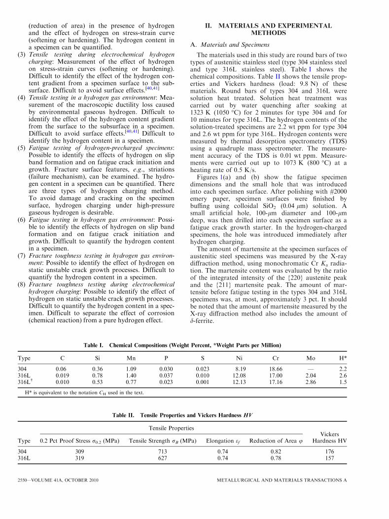
The materials used in this study are round bars of twotypes of austenitic stainless steel (type 304 stainless steeland type 316L stainless steel). Table I shows thechemical compositions. Table II shows the tensile prop-erties and Vickers hardness (load: 9.8 N) of thesematerials. Round bars of types 304 and 316L weresolution heat treated. Solution heat treatment wascarried out by water quenching after soaking at1323 K (1050 �C) for 2 minutes for type 304 and for10 minutes for type 316L. The hydrogen contents of thesolution-treated specimens are 2.2 wt ppm for type 304and 2.6 wt ppm for type 316L. Hydrogen contents weremeasured by thermal desorption spectrometry (TDS)using a quadruple mass spectrometer. The measure-ment accuracy of the TDS is 0.01 wt ppm. Measure-ments were carried out up to 1073 K (800 �C) at aheating rate of 0.5 K/s.Figures 1(a) and (b) show the fatigue specimen
dimensions and the small hole that was introducedinto each specimen surface. After polishing with #2000emery paper, specimen surfaces were finished bybuffing using colloidal SiO2 (0.04 lm) solution. Asmall artificial hole, 100-lm diameter and 100-lmdeep, was then drilled into each specimen surface as afatigue crack growth starter. In the hydrogen-chargedspecimens, the hole was introduced immediately afterhydrogen charging.The amount of martensite at the specimen surfaces of
austenitic steel specimens was measured by the X-raydiffraction method, using monochromatic Cr Ka radia-tion. The martensite content was evaluated by the ratioof the integrated intensity of the {220} austenite peakand the {211} martensite peak. The amount of mar-tensite before fatigue testing in the types 304 and 316Lspecimens was, at most, approximately 3 pct. It shouldbe noted that the amount of martensite measured by theX-ray diffraction method also includes the amount ofd-ferrite.
Table I. Chemical Compositions (Weight Percent, *Weight Parts per Million)
Type C Si Mn P S Ni Cr Mo H*
304 0.06 0.36 1.09 0.030 0.023 8.19 18.66 — 2.2316L 0.019 0.78 1.40 0.037 0.010 12.08 17.00 2.04 2.6316L� 0.010 0.53 0.77 0.023 0.001 12.13 17.16 2.86 1.5
H* is equivalent to the notation CH used in the text.
Table II. Tensile Properties and Vickers Hardness HV
Type
Tensile PropertiesVickers
Hardness HV0.2 Pct Proof Stress r0.2 (MPa) Tensile Strength rB (MPa) Elongation ef Reduction of Area u
304 309 713 0.74 0.82 176316L 319 627 0.74 0.78 157
2550—VOLUME 41A, OCTOBER 2010 METALLURGICAL AND MATERIALS TRANSACTIONS A
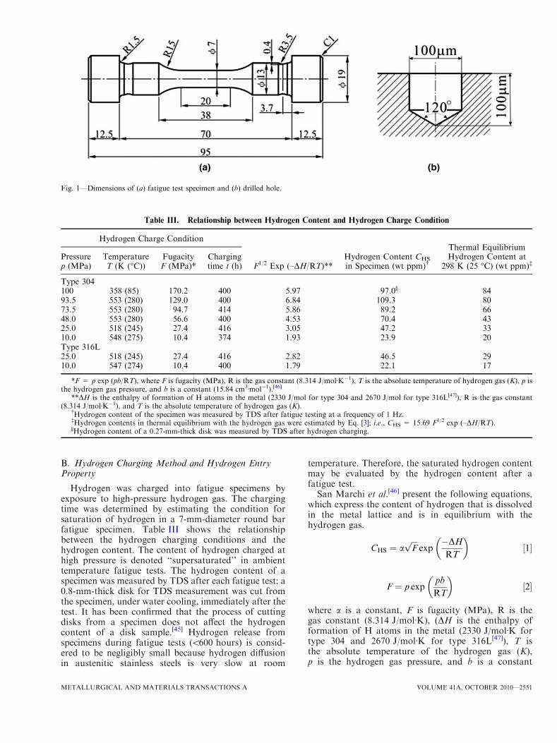
B. Hydrogen Charging Method and Hydrogen EntryProperty
Hydrogen was charged into fatigue specimens byexposure to high-pressure hydrogen gas. The chargingtime was determined by estimating the condition forsaturation of hydrogen in a 7-mm-diameter round barfatigue specimen. Table III shows the relationshipbetween the hydrogen charging conditions and thehydrogen content. The content of hydrogen charged athigh pressure is denoted ‘‘supersaturated’’ in ambienttemperature fatigue tests. The hydrogen content of aspecimen was measured by TDS after each fatigue test; a0.8-mm-thick disk for TDS measurement was cut fromthe specimen, under water cooling, immediately after thetest. It has been confirmed that the process of cuttingdisks from a specimen does not affect the hydrogencontent of a disk sample.[45] Hydrogen release fromspecimens during fatigue tests (<600 hours) is consid-ered to be negligibly small because hydrogen diffusionin austenitic stainless steels is very slow at room
temperature. Therefore, the saturated hydrogen contentmay be evaluated by the hydrogen content after afatigue test.San Marchi et al.[46] present the following equations,
which express the content of hydrogen that is dissolvedin the metal lattice and is in equilibrium with thehydrogen gas.
CHS ¼ affiffiffi
Fp
exp�DHRT
� �
½1�
F ¼ p exppb
RT
� �
½2�
where a is a constant, F is fugacity (MPa), R is thegas constant (8.314 J/molÆK), (DH is the enthalpy offormation of H atoms in the metal (2330 J/molÆK fortype 304 and 2670 J/molÆK for type 316L[47]), T isthe absolute temperature of the hydrogen gas (K),p is the hydrogen gas pressure, and b is a constant
Fig. 1—Dimensions of (a) fatigue test specimen and (b) drilled hole.
Table III. Relationship between Hydrogen Content and Hydrogen Charge Condition
Hydrogen Charge Condition
F1/2 Exp (–DH/RT)**Hydrogen Content CHS
in Specimen (wt ppm)�
Thermal EquilibriumHydrogen Content at
298 K (25 �C) (wt ppm)�Pressurep (MPa)
TemperatureT (K (�C))
FugacityF (MPa)*
Chargingtime t (h)
Type 304100 358 (85) 170.2 400 5.97 97.0§ 8493.5 553 (280) 129.0 400 6.84 109.3 8073.5 553 (280) 94.7 414 5.86 89.2 6648.0 553 (280) 56.6 400 4.53 70.4 4325.0 518 (245) 27.4 416 3.05 47.2 3310.0 548 (275) 10.4 374 1.93 23.9 20Type 316L25.0 518 (245) 27.4 416 2.82 46.5 2910.0 547 (274) 10.4 400 1.79 22.1 17
*F = p exp (pb/RT), where F is fugacity (MPa), R is the gas constant (8.314 J/molÆK�1), T is the absolute temperature of hydrogen gas (K), p isthe hydrogen gas pressure, and b is a constant (15.84 cm3Æmol�1).[46]
**DH is the enthalpy of formation of H atoms in the metal (2330 J/mol for type 304 and 2670 J/mol for type 316L[47]), R is the gas constant(8.314 J/molÆK�1), and T is the absolute temperature of hydrogen gas (K).
�Hydrogen content of the specimen was measured by TDS after fatigue testing at a frequency of 1 Hz.�Hydrogen contents in thermal equilibrium with the hydrogen gas were estimated by Eq. [3]; i.e., CHS = 15.69 F1/2 exp (–DH/RT).§Hydrogen content of a 0.27-mm-thick disk was measured by TDS after hydrogen charging.
METALLURGICAL AND MATERIALS TRANSACTIONS A VOLUME 41A, OCTOBER 2010—2551
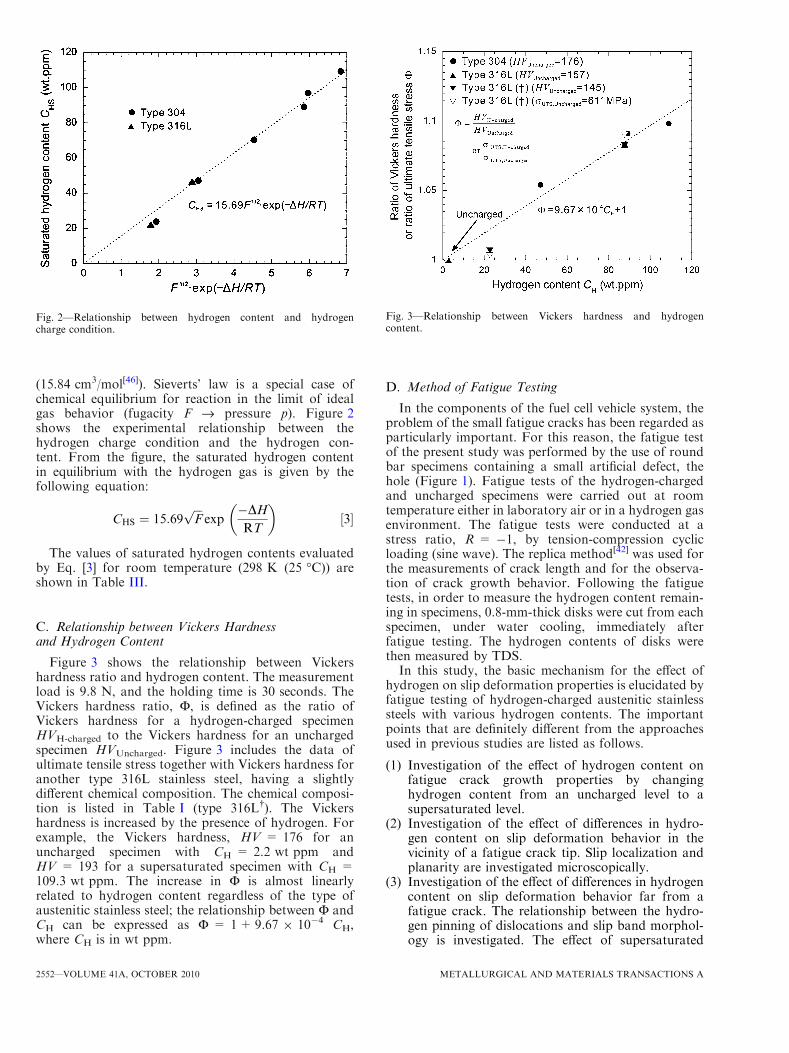
(15.84 cm3/mol[46]). Sieverts’ law is a special case ofchemical equilibrium for reaction in the limit of idealgas behavior (fugacity F fi pressure p). Figure 2shows the experimental relationship between thehydrogen charge condition and the hydrogen con-tent. From the figure, the saturated hydrogen contentin equilibrium with the hydrogen gas is given by thefollowing equation:
CHS ¼ 15:69ffiffiffi
Fp
exp�DHRT
� �
½3�
The values of saturated hydrogen contents evaluatedby Eq. [3] for room temperature (298 K (25 �C)) areshown in Table III.
C. Relationship between Vickers Hardnessand Hydrogen Content
Figure 3 shows the relationship between Vickershardness ratio and hydrogen content. The measurementload is 9.8 N, and the holding time is 30 seconds. TheVickers hardness ratio, F, is defined as the ratio ofVickers hardness for a hydrogen-charged specimenHVH-charged to the Vickers hardness for an unchargedspecimen HVUncharged. Figure 3 includes the data ofultimate tensile stress together with Vickers hardness foranother type 316L stainless steel, having a slightlydifferent chemical composition. The chemical composi-tion is listed in Table I (type 316L�). The Vickershardness is increased by the presence of hydrogen. Forexample, the Vickers hardness, HV = 176 for anuncharged specimen with CH = 2.2 wt ppm andHV = 193 for a supersaturated specimen with CH =109.3 wt ppm. The increase in F is almost linearlyrelated to hydrogen content regardless of the type ofaustenitic stainless steel; the relationship between F andCH can be expressed as F = 1+9.67 9 10�4 CH,where CH is in wt ppm.
D. Method of Fatigue Testing
In the components of the fuel cell vehicle system, theproblem of the small fatigue cracks has been regarded asparticularly important. For this reason, the fatigue testof the present study was performed by the use of roundbar specimens containing a small artificial defect, thehole (Figure 1). Fatigue tests of the hydrogen-chargedand uncharged specimens were carried out at roomtemperature either in laboratory air or in a hydrogen gasenvironment. The fatigue tests were conducted at astress ratio, R = �1, by tension-compression cyclicloading (sine wave). The replica method[42] was used forthe measurements of crack length and for the observa-tion of crack growth behavior. Following the fatiguetests, in order to measure the hydrogen content remain-ing in specimens, 0.8-mm-thick disks were cut from eachspecimen, under water cooling, immediately afterfatigue testing. The hydrogen contents of disks werethen measured by TDS.In this study, the basic mechanism for the effect of
hydrogen on slip deformation properties is elucidated byfatigue testing of hydrogen-charged austenitic stainlesssteels with various hydrogen contents. The importantpoints that are definitely different from the approachesused in previous studies are listed as follows.
(1) Investigation of the effect of hydrogen content onfatigue crack growth properties by changinghydrogen content from an uncharged level to asupersaturated level.
(2) Investigation of the effect of differences in hydro-gen content on slip deformation behavior in thevicinity of a fatigue crack tip. Slip localization andplanarity are investigated microscopically.
(3) Investigation of the effect of differences in hydrogencontent on slip deformation behavior far from afatigue crack. The relationship between the hydro-gen pinning of dislocations and slip band morphol-ogy is investigated. The effect of supersaturated
Fig. 2—Relationship between hydrogen content and hydrogencharge condition.
Fig. 3—Relationship between Vickers hardness and hydrogencontent.
2552—VOLUME 41A, OCTOBER 2010 METALLURGICAL AND MATERIALS TRANSACTIONS A
hydrogen on slip deformation behavior is investi-gated microscopically.
(4) The relationship between hydrogen diffusion rateand strain rate (dislocation mobility) is investigatedby focusing on the effects of test frequency and ofhydrogen on fatigue crack growth.
As mentioned in Section I, there are several experi-mental methods for investigating HE mechanisms. Itwill be seen in the following section that the observationof fatigue crack growth behavior, by using the replicamethod, is most pertinent to visualization of themechanism of the interaction between hydrogen anddislocations.
III. RESULTS AND DISCUSSION
A. Effects of Hydrogen Content and Cyclic LoadingFrequency, f, on Fatigue Crack Growth Properties
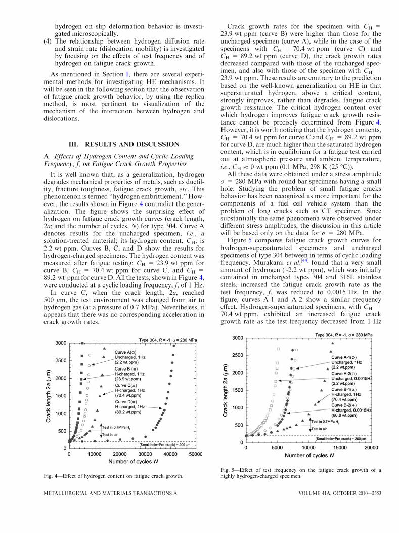
It is well known that, as a generalization, hydrogendegrades mechanical properties of metals, such as ductil-ity, fracture toughness, fatigue crack growth, etc. Thisphenomenon is termed ‘‘hydrogen embrittlement.’’ How-ever, the results shown in Figure 4 contradict the gener-alization. The figure shows the surprising effect ofhydrogen on fatigue crack growth curves (crack length,2a; and the number of cycles, N) for type 304. Curve Adenotes results for the uncharged specimen, i.e., asolution-treated material; its hydrogen content, CH, is2.2 wt ppm. Curves B, C, and D show the results forhydrogen-charged specimens. The hydrogen content wasmeasured after fatigue testing: CH = 23.9 wt ppm forcurve B, CH = 70.4 wt ppm for curve C, and CH =89.2 wt ppm for curveD.All the tests, shown in Figure 4,were conducted at a cyclic loading frequency, f, of 1 Hz.
In curve C, when the crack length, 2a, reached500 lm, the test environment was changed from air tohydrogen gas (at a pressure of 0.7 MPa). Nevertheless, itappears that there was no corresponding acceleration incrack growth rates.
Crack growth rates for the specimen with CH =23.9 wt ppm (curve B) were higher than those for theuncharged specimen (curve A), while in the case of thespecimens with CH = 70.4 wt ppm (curve C) andCH = 89.2 wt ppm (curve D), the crack growth ratesdecreased compared with those of the uncharged spec-imen, and also with those of the specimen with CH =23.9 wt ppm. These results are contrary to the predictionbased on the well-known generalization on HE in thatsupersaturated hydrogen, above a critical content,strongly improves, rather than degrades, fatigue crackgrowth resistance. The critical hydrogen content overwhich hydrogen improves fatigue crack growth resis-tance cannot be precisely determined from Figure 4.However, it is worth noticing that the hydrogen contents,CH = 70.4 wt ppm for curve C and CH = 89.2 wt ppmfor curve D, are much higher than the saturated hydrogencontent, which is in equilibrium for a fatigue test carriedout at atmospheric pressure and ambient temperature,i.e., CH � 0 wt ppm (0.1 MPa, 298 K (25 �C)).All these data were obtained under a stress amplitude
r = 280 MPa with round bar specimens having a smallhole. Studying the problem of small fatigue cracksbehavior has been recognized as more important for thecomponents of a fuel cell vehicle system than theproblem of long cracks such as CT specimen. Sincesubstantially the same phenomena were observed underdifferent stress amplitudes, the discussion in this articlewill be based only on the data for r = 280 MPa.Figure 5 compares fatigue crack growth curves for
hydrogen-supersaturated specimens and unchargedspecimens of type 304 between in terms of cyclic loadingfrequency. Murakami et al.[44] found that a very smallamount of hydrogen (~2.2 wt ppm), which was initiallycontained in uncharged types 304 and 316L stainlesssteels, increased the fatigue crack growth rate as thetest frequency, f, was reduced to 0.0015 Hz. In thefigure, curves A-1 and A-2 show a similar frequencyeffect. Hydrogen-supersaturated specimens, with CH =70.4 wt ppm, exhibited an increased fatigue crackgrowth rate as the test frequency decreased from 1 Hz
Fig. 4—Effect of hydrogen content on fatigue crack growth.Fig. 5—Effect of test frequency on the fatigue crack growth of ahighly hydrogen-charged specimen.
METALLURGICAL AND MATERIALS TRANSACTIONS A VOLUME 41A, OCTOBER 2010—2553
(curve B-1) to 0.0015 Hz (curve B-2). It is interesting tonote that curve B-2, with CH = 60.8 wt ppm andfrequency of 0.0015Hz, is very similar to curve A-1,which was obtained by testing uncharged specimenswith CH = 2.2 wt ppm at a frequency of 1 Hz. Thus,fatigue crack growth resistance can be improved bycharging abundant hydrogen into austenitic stainlesssteels.
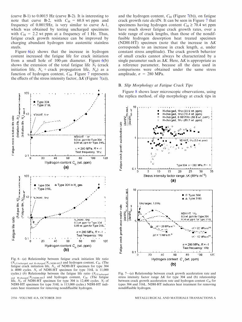
Figure 6(a) shows that the increase in hydrogencontent increased the fatigue life for crack initiationfrom a small hole of 100-lm diameter. Figure 6(b)shows the extension of the total fatigue life Nf (crackinitiation life, Nc+ crack propagation life, Np) as afunction of hydrogen content, CH. Figure 7 representsthe effects of the stress intensity factor, DK (Figure 7(a)),
and the hydrogen content, CH (Figure 7(b)), on fatiguecrack growth rate da/dN. It can be seen in Figure 7 thatspecimens having hydrogen content CH ‡ 70.4 wt ppmhave much slower fatigue crack growth rates, over awide range of crack lengths, than those of the nondif-fusible hydrogen desorption heat treated specimen(NDH-HT) specimen (note that the increase in DKcorresponds to an increase in crack length, a, underconstant stress amplitude). The crack growth behaviorof small cracks cannot always be characterized by asingle parameter such as DK. Here, DK is appropriate asa reference parameter, because all the data used incomparisons were obtained under the same stressamplitude, r = 280 MPa.
B. Slip Morphology at Fatigue Crack Tips
Figure 8 shows laser microscopic observations, usingthe replica method, of slip morphology at crack tips in
Fig. 6—(a) Relationship between fatigue crack initiation life ratio(Nc,Uncharged and H-charged/Nc,NDH-HT) and hydrogen content, CH. (Thefatigue crack initiation life, Nc, of NDH-HT specimen for type 304is 4000 cycles. Nc of NDH-HT specimen for type 316L is 11,000cycles.) (b) Relationship between the fatigue life ratio (Nf,Uncharged
and H-charged/Nf,NDH-HT) and hydrogen content, CH. (The fatiguelife, Nf, of NDH-HT specimen for type 304 is 12,400 cycles. Nf ofNDH-HT specimen for type 316L is 113,000 cycles.) NDH-HT indi-cates heat treatment for removing nondiffusible hydrogen.
Fig. 7—(a) Relationship between crack growth acceleration rate andstress intensity factor range DK for type 304 and (b) relationshipbetween crack growth acceleration rate and hydrogen content CH fortypes 304 and 316L. NDH-HT indicates heat treatment for removingnondiffusible hydrogen.
2554—VOLUME 41A, OCTOBER 2010 METALLURGICAL AND MATERIALS TRANSACTIONS A
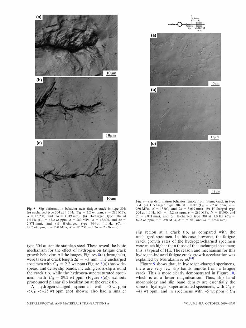
type 304 austenitic stainless steel. These reveal the basicmechanism for the effect of hydrogen on fatigue crackgrowthbehavior.All the images, Figures 8(a) through (c),were taken at crack length 2a = ~3 mm. The unchargedspecimen withCH = 2.2 wt ppm (Figure 8(a)) has wide-spread and dense slip bands, including cross-slip aroundthe crack tip, while the hydrogen-supersaturated speci-men, with CH = 89.2 wt ppm (Figure 8(c)), exhibitspronounced planar slip localization at the crack tip.
A hydrogen-charged specimen with ~5 wt ppm<CH < ~25 wt ppm (not shown) also had a smaller
slip region at a crack tip, as compared with theuncharged specimen. In this case, however, the fatiguecrack growth rates of the hydrogen-charged specimenwere much higher than those of the uncharged specimen;this is typical of HE. The reason and mechanism for thishydrogen-induced fatigue crack growth acceleration wasexplained by Murakami et al.[44]
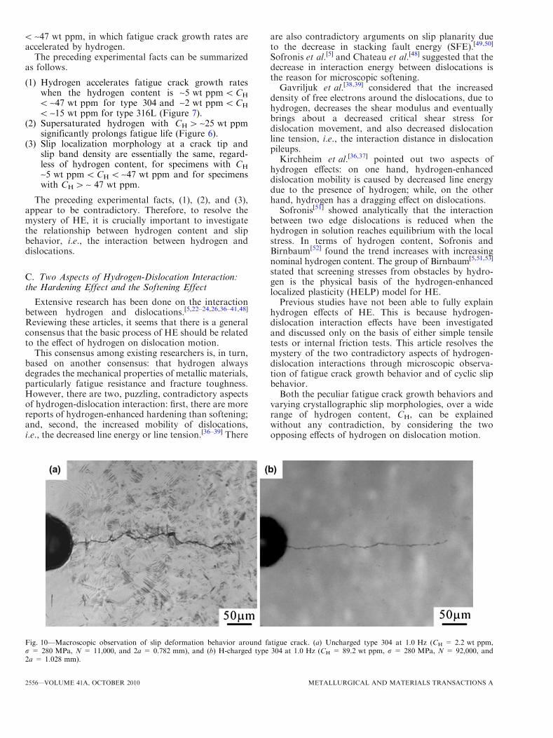
Figure 9 shows that, in hydrogen-charged specimens,there are very few slip bands remote from a fatiguecrack. This is more clearly demonstrated in Figure 10,which is at a lower magnification. Thus, slip bandmorphology and slip band density are essentially thesame in hydrogen-supersaturated specimens, with CH >~47 wt ppm, and in specimens with ~5 wt ppm<CH
Fig. 8—Slip deformation behavior near fatigue crack in type 304:(a) uncharged type 304 at 1.0 Hz (CH = 2.2 wt ppm, r = 280 MPa,N = 13,200, and 2a = 3.019 mm), (b) H-charged type 304 at1.0 Hz (CH = 47.2 wt ppm, r = 280 MPa, N = 18,400, and 2a =2.871 mm), and (c) H-charged type 304 at 1.0 Hz (CH =89.2 wt ppm, r = 280 MPa, N = 96,200, and 2a = 2.926 mm).
Fig. 9—Slip deformation behavior remote from fatigue crack in type304. (a) Uncharged type 304 at 1.0 Hz (CH = 2.2 wt ppm, r =280 MPa, N = 13200, and 2a = 3.019 mm), (b) H-charged type304 at 1.0 Hz (CH = 47.2 wt ppm, r = 280 MPa, N = 18,400, and2a = 2.871 mm), and (c) H-charged type 304 at 1.0 Hz (CH =89.2 wt ppm, r = 280 MPa, N = 96200, and 2a = 2.926 mm).
METALLURGICAL AND MATERIALS TRANSACTIONS A VOLUME 41A, OCTOBER 2010—2555
< ~47 wt ppm, in which fatigue crack growth rates areaccelerated by hydrogen.
The preceding experimental facts can be summarizedas follows.
(1) Hydrogen accelerates fatigue crack growth rateswhen the hydrogen content is ~5 wt ppm<CH
< ~47 wt ppm for type 304 and ~2 wt ppm<CH
< ~15 wt ppm for type 316L (Figure 7).(2) Supersaturated hydrogen with CH > ~25 wt ppm
significantly prolongs fatigue life (Figure 6).(3) Slip localization morphology at a crack tip and
slip band density are essentially the same, regard-less of hydrogen content, for specimens with CH
~5 wt ppm<CH < ~47 wt ppm and for specimenswith CH > ~ 47 wt ppm.
The preceding experimental facts, (1), (2), and (3),appear to be contradictory. Therefore, to resolve themystery of HE, it is crucially important to investigatethe relationship between hydrogen content and slipbehavior, i.e., the interaction between hydrogen anddislocations.
C. Two Aspects of Hydrogen-Dislocation Interaction:the Hardening Effect and the Softening Effect
Extensive research has been done on the interactionbetween hydrogen and dislocations.[5,22–24,26,36–41,48]
Reviewing these articles, it seems that there is a generalconsensus that the basic process of HE should be relatedto the effect of hydrogen on dislocation motion.
This consensus among existing researchers is, in turn,based on another consensus: that hydrogen alwaysdegrades the mechanical properties of metallic materials,particularly fatigue resistance and fracture toughness.However, there are two, puzzling, contradictory aspectsof hydrogen-dislocation interaction: first, there are morereports of hydrogen-enhanced hardening than softening;and, second, the increased mobility of dislocations,i.e., the decreased line energy or line tension.[36–39] There
are also contradictory arguments on slip planarity dueto the decrease in stacking fault energy (SFE).[49,50]
Sofronis et al.[5] and Chateau et al.[48] suggested that thedecrease in interaction energy between dislocations isthe reason for microscopic softening.Gavriljuk et al.[38,39] considered that the increased
density of free electrons around the dislocations, due tohydrogen, decreases the shear modulus and eventuallybrings about a decreased critical shear stress fordislocation movement, and also decreased dislocationline tension, i.e., the interaction distance in dislocationpileups.Kirchheim et al.[36,37] pointed out two aspects of
hydrogen effects: on one hand, hydrogen-enhanceddislocation mobility is caused by decreased line energydue to the presence of hydrogen; while, on the otherhand, hydrogen has a dragging effect on dislocations.Sofronis[51] showed analytically that the interaction
between two edge dislocations is reduced when thehydrogen in solution reaches equilibrium with the localstress. In terms of hydrogen content, Sofronis andBirnbaum[52] found the trend increases with increasingnominal hydrogen content. The group of Birnbaum[5,51,53]
stated that screening stresses from obstacles by hydro-gen is the physical basis of the hydrogen-enhancedlocalized plasticity (HELP) model for HE.Previous studies have not been able to fully explain
hydrogen effects of HE. This is because hydrogen-dislocation interaction effects have been investigatedand discussed only on the basis of either simple tensiletests or internal friction tests. This article resolves themystery of the two contradictory aspects of hydrogen-dislocation interactions through microscopic observa-tion of fatigue crack growth behavior and of cyclic slipbehavior.Both the peculiar fatigue crack growth behaviors and
varying crystallographic slip morphologies, over a widerange of hydrogen content, CH, can be explainedwithout any contradiction, by considering the twoopposing effects of hydrogen on dislocation motion.
Fig. 10—Macroscopic observation of slip deformation behavior around fatigue crack. (a) Uncharged type 304 at 1.0 Hz (CH = 2.2 wt ppm,r = 280 MPa, N = 11,000, and 2a = 0.782 mm), and (b) H-charged type 304 at 1.0 Hz (CH = 89.2 wt ppm, r = 280 MPa, N = 92,000, and2a = 1.028 mm).
2556—VOLUME 41A, OCTOBER 2010 METALLURGICAL AND MATERIALS TRANSACTIONS A
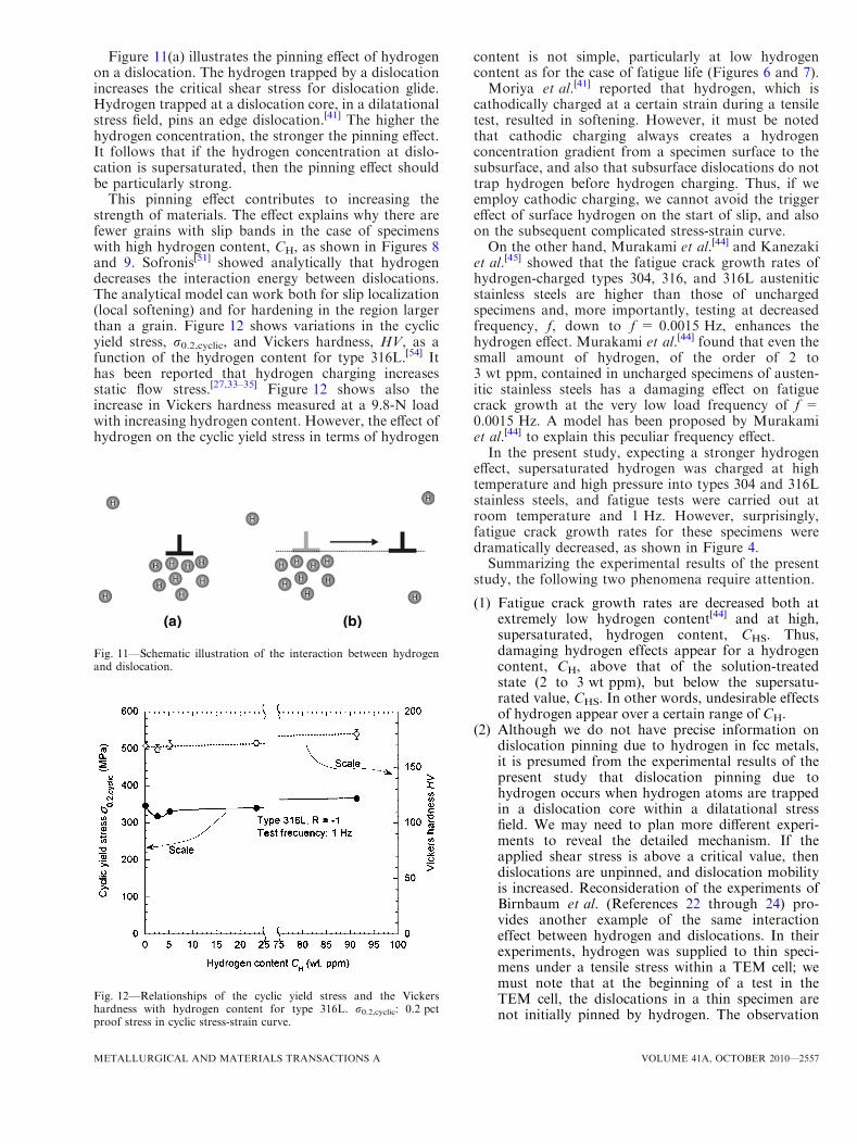
Figure 11(a) illustrates the pinning effect of hydrogenon a dislocation. The hydrogen trapped by a dislocationincreases the critical shear stress for dislocation glide.Hydrogen trapped at a dislocation core, in a dilatationalstress field, pins an edge dislocation.[41] The higher thehydrogen concentration, the stronger the pinning effect.It follows that if the hydrogen concentration at dislo-cation is supersaturated, then the pinning effect shouldbe particularly strong.
This pinning effect contributes to increasing thestrength of materials. The effect explains why there arefewer grains with slip bands in the case of specimenswith high hydrogen content, CH, as shown in Figures 8and 9. Sofronis[51] showed analytically that hydrogendecreases the interaction energy between dislocations.The analytical model can work both for slip localization(local softening) and for hardening in the region largerthan a grain. Figure 12 shows variations in the cyclicyield stress, r0.2,cyclic, and Vickers hardness, HV, as afunction of the hydrogen content for type 316L.[54] Ithas been reported that hydrogen charging increasesstatic flow stress.[27,33–35] Figure 12 shows also theincrease in Vickers hardness measured at a 9.8-N loadwith increasing hydrogen content. However, the effect ofhydrogen on the cyclic yield stress in terms of hydrogen
content is not simple, particularly at low hydrogencontent as for the case of fatigue life (Figures 6 and 7).Moriya et al.[41] reported that hydrogen, which is
cathodically charged at a certain strain during a tensiletest, resulted in softening. However, it must be notedthat cathodic charging always creates a hydrogenconcentration gradient from a specimen surface to thesubsurface, and also that subsurface dislocations do nottrap hydrogen before hydrogen charging. Thus, if weemploy cathodic charging, we cannot avoid the triggereffect of surface hydrogen on the start of slip, and alsoon the subsequent complicated stress-strain curve.On the other hand, Murakami et al.[44] and Kanezaki
et al.[45] showed that the fatigue crack growth rates ofhydrogen-charged types 304, 316, and 316L austeniticstainless steels are higher than those of unchargedspecimens and, more importantly, testing at decreasedfrequency, f, down to f = 0.0015 Hz, enhances thehydrogen effect. Murakami et al.[44] found that even thesmall amount of hydrogen, of the order of 2 to3 wt ppm, contained in uncharged specimens of austen-itic stainless steels has a damaging effect on fatiguecrack growth at the very low load frequency of f =0.0015 Hz. A model has been proposed by Murakamiet al.[44] to explain this peculiar frequency effect.In the present study, expecting a stronger hydrogen
effect, supersaturated hydrogen was charged at hightemperature and high pressure into types 304 and 316Lstainless steels, and fatigue tests were carried out atroom temperature and 1 Hz. However, surprisingly,fatigue crack growth rates for these specimens weredramatically decreased, as shown in Figure 4.Summarizing the experimental results of the present
study, the following two phenomena require attention.
(1) Fatigue crack growth rates are decreased both atextremely low hydrogen content[44] and at high,supersaturated, hydrogen content, CHS. Thus,damaging hydrogen effects appear for a hydrogencontent, CH, above that of the solution-treatedstate (2 to 3 wt ppm), but below the supersatu-rated value, CHS. In other words, undesirable effectsof hydrogen appear over a certain range of CH.
(2) Although we do not have precise information ondislocation pinning due to hydrogen in fcc metals,it is presumed from the experimental results of thepresent study that dislocation pinning due tohydrogen occurs when hydrogen atoms are trappedin a dislocation core within a dilatational stressfield. We may need to plan more different experi-ments to reveal the detailed mechanism. If theapplied shear stress is above a critical value, thendislocations are unpinned, and dislocation mobilityis increased. Reconsideration of the experiments ofBirnbaum et al. (References 22 through 24) pro-vides another example of the same interactioneffect between hydrogen and dislocations. In theirexperiments, hydrogen was supplied to thin speci-mens under a tensile stress within a TEM cell; wemust note that at the beginning of a test in theTEM cell, the dislocations in a thin specimen arenot initially pinned by hydrogen. The observation
Fig. 11—Schematic illustration of the interaction between hydrogenand dislocation.
Fig. 12—Relationships of the cyclic yield stress and the Vickershardness with hydrogen content for type 316L. r0.2,cyclic: 0.2 pctproof stress in cyclic stress-strain curve.
METALLURGICAL AND MATERIALS TRANSACTIONS A VOLUME 41A, OCTOBER 2010—2557
of increased dislocation mobility in the internalfriction tests of Gavriljuk et al.[38,39] also indicatesa softening effect, not by the initially stationarydislocations, but by interaction between hydrogenatoms and mobile dislocations that have beenreleased from pinning by hydrogen. It follows thatthe basic mechanism of the phenomenon observedby Birnbaum et al. is essentially the same as thatobserved by Gavriljuk et al.
Figure 11(b) illustrates hydrogen atoms left behind anedge dislocation core after it is released from pinningand moves (Figure 11(a)). Although these hydrogenatoms move with time toward another dislocation corewithin a dilatational stress field (molecular dynamicanalysis by Kakimoto[55]), the dislocation mobility isenhanced as long as these dislocations are located apartfrom the latter dislocation (molecular dynamics analysisby Taketomi et al.[56]).
Under this condition, a dislocation continues to moveat a lower stress than the critical shear stress necessary torelease a dislocation that has been pinned by hydrogen.Such a dislocation movement activates Frank–Readsources and generates additional new dislocations; slip isconfined to planes and, in the presence of solutehydrogen, cross-slip is prevented. By contrast, in thesame specimen, further slip does not originate atdislocations that have not been released from pinningby hydrogen. The chain reaction of hydrogen-dislocationinteraction is presumed to be the cause of slip localiza-tion at fatigue crack tips. Sofronis[51] and Sofronis andBirnbaum[52] analyzed the problems of the interactionbetween dislocations and hydrogen atoms distributed atthe dilatation area of edge dislocations. In a similaranalysis, Chateau et al.[48] also reported a decrease ininteraction energy between co-planar dislocations. TheHELP model, which emphasizes screening stress fromobstacles by hydrogen atmospheres, may be the mostimportant basic model to explain the interaction betweenhydrogen and mobile dislocations. However, the fatiguecrack growth rate dramatically changes depending onhydrogen content, e.g., much decreased crack growthrate for the cases of almost zero H content andsupersaturated H content and increased crack growthrate for the case of a few ppm H content (Figure 7). Inorder to explain, without contradiction, the experimentalresults of the present study (supersaturated hydrogen),and also the results of the previous experiments[44]
(almost no hydrogen), it is necessary to consider theway of application of the HELP model to fatiguephenomena in relation to hydrogen content and fatiguecrack growth mechanism. If we interpret that the HELPmodel acts inside the fatigue process zone at crack tipand the zone outside the process zone does not satisfy thecritical condition of slip, the phenomena can be under-stood without contradiction.
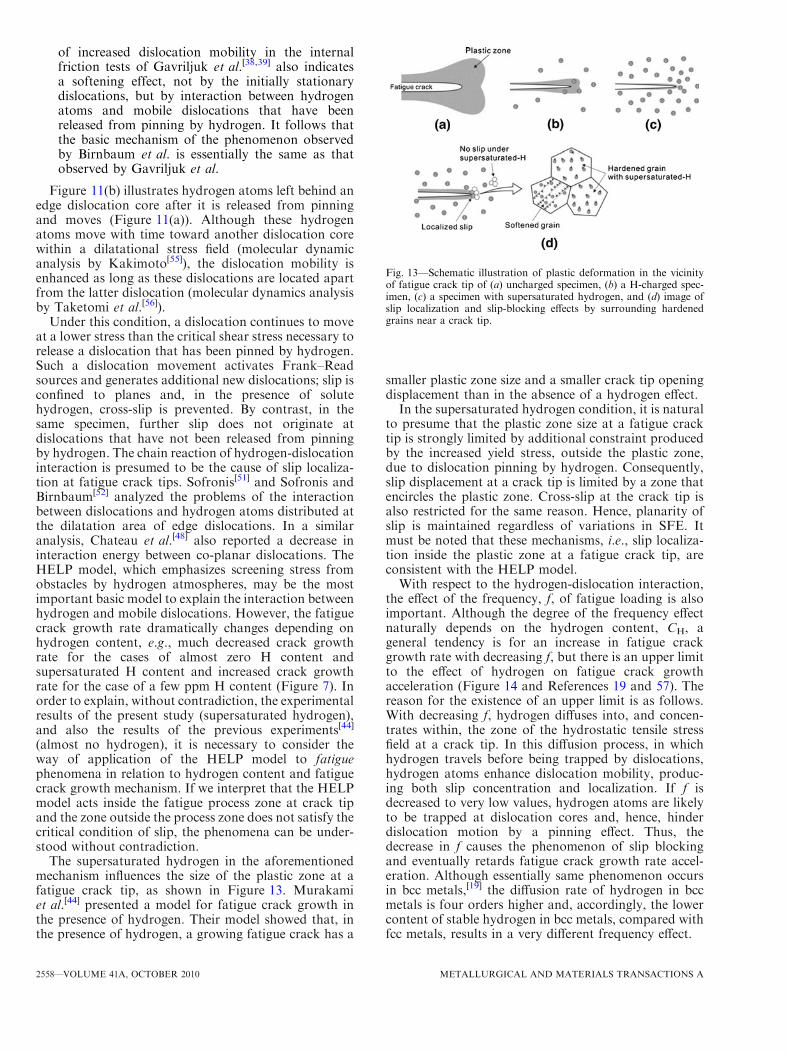
The supersaturated hydrogen in the aforementionedmechanism influences the size of the plastic zone at afatigue crack tip, as shown in Figure 13. Murakamiet al.[44] presented a model for fatigue crack growth inthe presence of hydrogen. Their model showed that, inthe presence of hydrogen, a growing fatigue crack has a
smaller plastic zone size and a smaller crack tip openingdisplacement than in the absence of a hydrogen effect.In the supersaturated hydrogen condition, it is natural
to presume that the plastic zone size at a fatigue cracktip is strongly limited by additional constraint producedby the increased yield stress, outside the plastic zone,due to dislocation pinning by hydrogen. Consequently,slip displacement at a crack tip is limited by a zone thatencircles the plastic zone. Cross-slip at the crack tip isalso restricted for the same reason. Hence, planarity ofslip is maintained regardless of variations in SFE. Itmust be noted that these mechanisms, i.e., slip localiza-tion inside the plastic zone at a fatigue crack tip, areconsistent with the HELP model.With respect to the hydrogen-dislocation interaction,
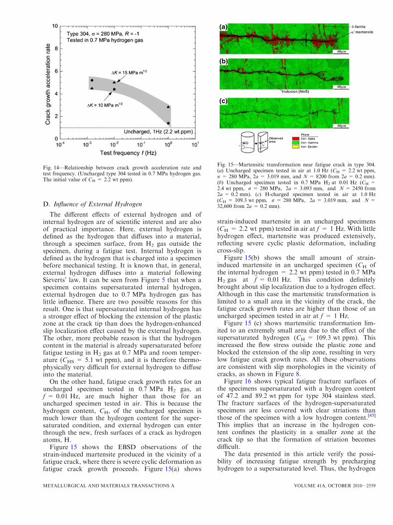
the effect of the frequency, f, of fatigue loading is alsoimportant. Although the degree of the frequency effectnaturally depends on the hydrogen content, CH, ageneral tendency is for an increase in fatigue crackgrowth rate with decreasing f, but there is an upper limitto the effect of hydrogen on fatigue crack growthacceleration (Figure 14 and References 19 and 57). Thereason for the existence of an upper limit is as follows.With decreasing f, hydrogen diffuses into, and concen-trates within, the zone of the hydrostatic tensile stressfield at a crack tip. In this diffusion process, in whichhydrogen travels before being trapped by dislocations,hydrogen atoms enhance dislocation mobility, produc-ing both slip concentration and localization. If f isdecreased to very low values, hydrogen atoms are likelyto be trapped at dislocation cores and, hence, hinderdislocation motion by a pinning effect. Thus, thedecrease in f causes the phenomenon of slip blockingand eventually retards fatigue crack growth rate accel-eration. Although essentially same phenomenon occursin bcc metals,[19] the diffusion rate of hydrogen in bccmetals is four orders higher and, accordingly, the lowercontent of stable hydrogen in bcc metals, compared withfcc metals, results in a very different frequency effect.
Fig. 13—Schematic illustration of plastic deformation in the vicinityof fatigue crack tip of (a) uncharged specimen, (b) a H-charged spec-imen, (c) a specimen with supersaturated hydrogen, and (d) image ofslip localization and slip-blocking effects by surrounding hardenedgrains near a crack tip.
2558—VOLUME 41A, OCTOBER 2010 METALLURGICAL AND MATERIALS TRANSACTIONS A
D. Influence of External Hydrogen
The different effects of external hydrogen and ofinternal hydrogen are of scientific interest and are alsoof practical importance. Here, external hydrogen isdefined as the hydrogen that diffuses into a material,through a specimen surface, from H2 gas outside thespecimen, during a fatigue test. Internal hydrogen isdefined as the hydrogen that is charged into a specimenbefore mechanical testing. It is known that, in general,external hydrogen diffuses into a material followingSieverts’ law. It can be seen from Figure 5 that when aspecimen contains supersaturated internal hydrogen,external hydrogen due to 0.7 MPa hydrogen gas haslittle influence. There are two possible reasons for thisresult. One is that supersaturated internal hydrogen hasa stronger effect of blocking the extension of the plasticzone at the crack tip than does the hydrogen-enhancedslip localization effect caused by the external hydrogen.The other, more probable reason is that the hydrogencontent in the material is already supersaturated beforefatigue testing in H2 gas at 0.7 MPa and room temper-ature (CHS = 5.1 wt ppm), and it is therefore thermo-physically very difficult for external hydrogen to diffuseinto the material.
On the other hand, fatigue crack growth rates for anuncharged specimen tested in 0.7 MPa H2 gas, atf = 0.01 Hz, are much higher than those for anuncharged specimen tested in air. This is because thehydrogen content, CH, of the uncharged specimen ismuch lower than the hydrogen content for the super-saturated condition, and external hydrogen can enterthrough the new, fresh surfaces of a crack as hydrogenatoms, H.
Figure 15 shows the EBSD observations of thestrain-induced martensite produced in the vicinity of afatigue crack, where there is severe cyclic deformation asfatigue crack growth proceeds. Figure 15(a) shows
strain-induced martensite in an uncharged specimens(CH = 2.2 wt ppm) tested in air at f = 1 Hz. With littlehydrogen effect, martensite was produced extensively,reflecting severe cyclic plastic deformation, includingcross-slip.Figure 15(b) shows the small amount of strain-
induced martensite in an uncharged specimen (CH ofthe internal hydrogen = 2.2 wt ppm) tested in 0.7 MPaH2 gas at f = 0.01 Hz. This condition definitelybrought about slip localization due to a hydrogen effect.Although in this case the martensitic transformation islimited to a small area in the vicinity of the crack, thefatigue crack growth rates are higher than those of anuncharged specimen tested in air at f = 1 Hz.Figure 15 (c) shows martensitic transformation lim-
ited to an extremely small area due to the effect of thesupersaturated hydrogen (CH = 109.3 wt ppm). Thisincreased the flow stress outside the plastic zone andblocked the extension of the slip zone, resulting in verylow fatigue crack growth rates. All these observationsare consistent with slip morphologies in the vicinity ofcracks, as shown in Figure 8.Figure 16 shows typical fatigue fracture surfaces of
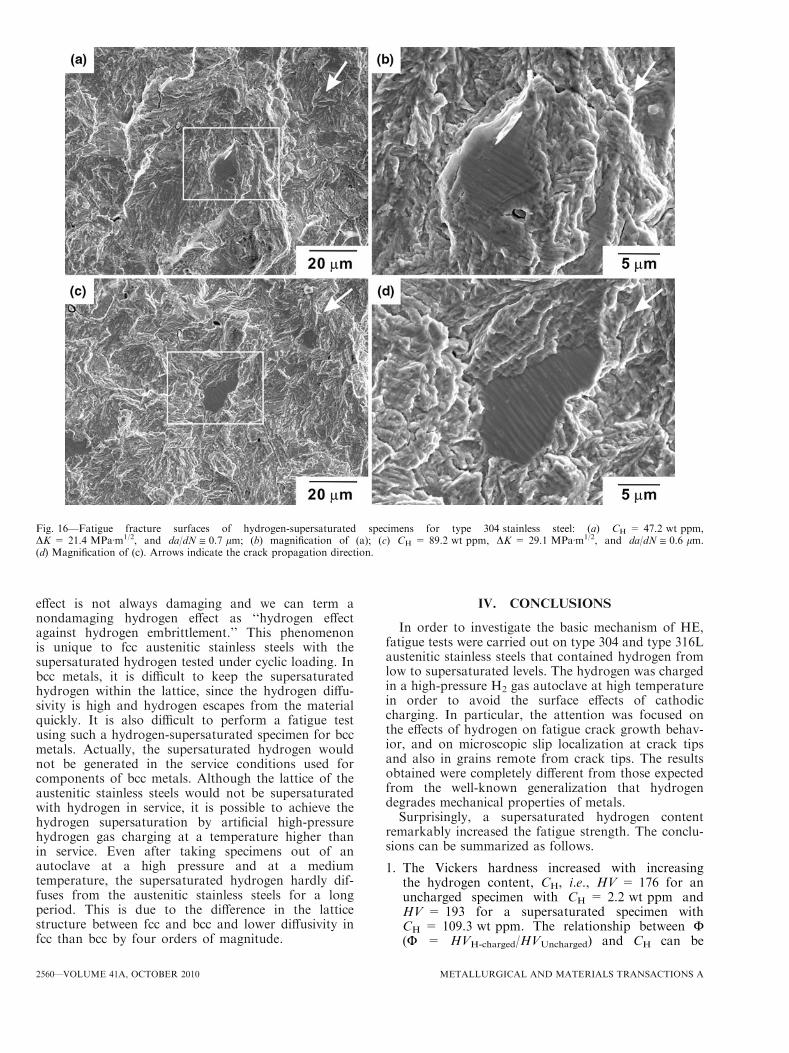
the specimens supersaturated with a hydrogen contentof 47.2 and 89.2 wt ppm for type 304 stainless steel.The fracture surfaces of the hydrogen-supersaturatedspecimens are less covered with clear striations thanthose of the specimen with a low hydrogen content.[45]
This implies that an increase in the hydrogen con-tent confines the plasticity in a smaller zone at thecrack tip so that the formation of striation becomesdifficult.The data presented in this article verify the possi-
bility of increasing fatigue strength by precharginghydrogen to a supersaturated level. Thus, the hydrogen
Fig. 14—Relationship between crack growth acceleration rate andtest frequency. (Uncharged type 304 tested in 0.7 MPa hydrogen gas.The initial value of CH = 2.2 wt ppm).
Fig. 15—Martensitic transformation near fatigue crack in type 304.(a) Uncharged specimen tested in air at 1.0 Hz (CH = 2.2 wt ppm,r = 280 MPa, 2a = 3.019 mm, and N = 8200 from 2a = 0.2 mm).(b) Uncharged specimen tested in 0.7 MPa H2 at 0.01 Hz (CH =2.4 wt ppm, r = 280 MPa, 2a = 3.093 mm, and N = 2450 from2a = 0.2 mm). (c) H-charged specimen tested in air at 1.0 Hz(CH = 109.3 wt ppm, r = 280 MPa, 2a = 3.019 mm, and N =32,600 from 2a = 0.2 mm).
METALLURGICAL AND MATERIALS TRANSACTIONS A VOLUME 41A, OCTOBER 2010—2559
effect is not always damaging and we can term anondamaging hydrogen effect as ‘‘hydrogen effectagainst hydrogen embrittlement.’’ This phenomenonis unique to fcc austenitic stainless steels with thesupersaturated hydrogen tested under cyclic loading. Inbcc metals, it is difficult to keep the supersaturatedhydrogen within the lattice, since the hydrogen diffu-sivity is high and hydrogen escapes from the materialquickly. It is also difficult to perform a fatigue testusing such a hydrogen-supersaturated specimen for bccmetals. Actually, the supersaturated hydrogen wouldnot be generated in the service conditions used forcomponents of bcc metals. Although the lattice of theaustenitic stainless steels would not be supersaturatedwith hydrogen in service, it is possible to achieve thehydrogen supersaturation by artificial high-pressurehydrogen gas charging at a temperature higher thanin service. Even after taking specimens out of anautoclave at a high pressure and at a mediumtemperature, the supersaturated hydrogen hardly dif-fuses from the austenitic stainless steels for a longperiod. This is due to the difference in the latticestructure between fcc and bcc and lower diffusivity infcc than bcc by four orders of magnitude.
IV. CONCLUSIONS
In order to investigate the basic mechanism of HE,fatigue tests were carried out on type 304 and type 316Laustenitic stainless steels that contained hydrogen fromlow to supersaturated levels. The hydrogen was chargedin a high-pressure H2 gas autoclave at high temperaturein order to avoid the surface effects of cathodiccharging. In particular, the attention was focused onthe effects of hydrogen on fatigue crack growth behav-ior, and on microscopic slip localization at crack tipsand also in grains remote from crack tips. The resultsobtained were completely different from those expectedfrom the well-known generalization that hydrogendegrades mechanical properties of metals.Surprisingly, a supersaturated hydrogen content
remarkably increased the fatigue strength. The conclu-sions can be summarized as follows.
1. The Vickers hardness increased with increasingthe hydrogen content, CH, i.e., HV = 176 for anuncharged specimen with CH = 2.2 wt ppm andHV = 193 for a supersaturated specimen withCH = 109.3 wt ppm. The relationship between F(F = HVH-charged/HVUncharged) and CH can be
Fig. 16—Fatigue fracture surfaces of hydrogen-supersaturated specimens for type 304 stainless steel: (a) CH = 47.2 wt ppm,DK = 21.4 MPaÆm1/2, and da/dN @ 0.7 lm; (b) magnification of (a); (c) CH = 89.2 wt ppm, DK = 29.1 MPaÆm1/2, and da/dN @ 0.6 lm.(d) Magnification of (c). Arrows indicate the crack propagation direction.
2560—VOLUME 41A, OCTOBER 2010 METALLURGICAL AND MATERIALS TRANSACTIONS A
expressed as F = 1+9.67 9 10�4 CH. This rela-tionship is consistent with the results of many otherresults in the literature that report a hardeningeffect due to hydrogen, rather than a softeningeffect. The cause of the increase in HV is presumedto be a dislocation pinning effect.
2. Cyclic slip appeared in many grains of anuncharged specimen (CH = 2.2 wt ppm), but underthe same stress amplitude, very few slip bands wereobserved in a charged specimen. This phenomenonfor the case of hydrogen content higher than a criti-cal value is also due to the hardening effect ofhydrogen.
3. Many slip bands, including cross-slip, were observedadjacent to the fatigue crack in an uncharged speci-men, together with much strain-induced martensite,while the slip bands in a hydrogen-charged specimenwere localized, with less cross-slip and less strain-induced martensite at the crack tip.
4. Up to a certain critical value of CH, fatigue crackgrowth rates increased compared with those for anuncharged specimen. However, above the criticalvalue of CH, fatigue crack growth was retarded,and the fatigue strength was markedly improved.This phenomenon should be denoted as ‘‘hydrogeneffect against HE.’’
5. The mysterious phenomena of (1) through (4) canbe explained as an interaction between hydrogenand dislocations, without contradicting hardeningand softening effects reported in the existing litera-ture. Hydrogen trapped at a dislocation corehinders dislocation motion. Once a dislocation is re-leased from pinning by hydrogen at its core, thenthe dislocation mobility is increased. However, asthe value of CH increases, the extension of the plas-tic zone at a crack tip is blocked by the surroundingmaterial, which has a higher flow stress. This phe-nomenon retards the fatigue crack growth rateregardless of the slip localization at a crack tip.Moreover, with decreasing test frequency, f, thefatigue crack growth rate increases but graduallyapproaches an upper limit of growth rate accelera-tion. The existence of this upper limit can beexplained as the result of competition between thehydrogen diffusion rate and the dislocation velocity,which, depending on the strain rate, determines thetrapping of hydrogen atoms at a dislocation core.All these conclusions are supported by microscopicobservation, made by using the replica method, andby EBSD observations on the strain-induced mar-tensitic transformation.
ACKNOWLEDGMENTS
The authors thank Professor P. Sofronis, Universityof Illinois, and Professor J. Solin, VTT TechnicalResearch Centre of Finland (currently Kyushu Univer-sity and HYDROGENIUS, AIST), for the usefuldiscussion and comments on the interaction betweenhydrogen and dislocations. This research has been
supported by the NEDO Fundamental Research Pro-ject on Advanced Hydrogen Science (2006 to 2012).
OPEN ACCESS
This article is distributed under the terms ofthe Creative Commons Attribution NoncommercialLicense which permits any noncommercial use, distri-bution, and reproduction in any medium, provided theoriginal author(s) and source are credited.
REFERENCES
1. A.R. Troiano: Trans. Am. Soc. Met., 1960, vol. 52, pp. 54–80.2. R.A. Oriani and P.H. Josephic: Acta Metall., 1974, vol. 22,
pp. 1065–74.3. C.D. Beachem: Metall. Trans., 1972, vol. 3, pp. 437–51.4. S.P. Lynch: Acta Metall., 1988, vol. 36, pp. 2639–61.5. H.K. Birnbaum and P. Sofronis: Mater. Sci. Eng. A, 1994,
vol. 176A, pp. 191–202.6. L. Zhong, R. Wu, A.J. Freeman, and G.B. Olson: Phys. Rev. B,
2000, vol. 62, pp. 13938–13941.7. G. Lu and E. Kaxiras: Phys. Rev. Lett., 2005, vol. 94, pp. 155501-
1–155501-4.8. R.M. Vennet and G.S. Ansell: Trans. Am. Soc. Met., 1967, vol. 60,
pp. 242–51.9. M.R. Louthan, Jr., G.R. Caskey, J.A. Donovan, and D.E. Rawl,
Jr.: Mater. Sci. Eng., 1972, vol. 10, pp. 357–68.10. H. Cialone and R.J. Asaro: Metall. Trans. A, 1979, vol. 10A,
pp. 367–75.11. R.E. Stoltz and A.J. West: in Hydrogen Effects in Metals, I.M.
Bernstein and A.W. Thompson, eds., AIME, Warrendale, PA,1981, pp. 541–53.
12. S.L. Robinson and N.R. Moody: J. Nucl. Mater., 1986, vol. 140,pp. 245–51.
13. M.-J. Lii, X.-F. Chen, Y. Katz, and W.W. Gerberich: Acta Metall.Mater., 1990, vol. 38, pp. 2435–53.
14. J. Toplosky and R.O. Ritchie: Scripta Metall., 1981, vol. 15,pp. 905–08.
15. T.B. McLaren and A.W. Thompson: Mater. Sci. Eng., 1983,vol. 57, pp. L21–L25.
16. G. Schuster and C. Altstetter: Metall. Trans. A, 1983, vol. 14A,pp. 2085–90.
17. M. Itatani, Y. Miyoshi, and K. Ogura: Eng. Fract. Mech., 1988,vol. 30, pp. 337–48.
18. Y. Murakami: Int. J. Fract., 2006, vol. 138, pp. 167–95.19. H. Tanaka, N. Homma, S. Matsuoka, and Y. Murakami: Trans.
Jpn. Soc. Mech. Eng. A, 2007, vol. 73, pp. 1358–65 (in Japanese).20. Y. Murakami, T. Kanezaki, Y. Fukushima, H. Tanaka, J.
Tomuro, K. Kuboyama, M. Matsue, Y. Ito, and H. Ando: Trans.Jpn. Soc. Mech. Eng. A, 2009, vol. 75, pp. 93–102 (in Japanese).
21. M.R. Louthan, Jr.: Scripta Metall., 1983, vol. 17, pp. 451–54.22. T. Tabata and H.K. Birnbaum: Scripta Metall., 1984, vol. 18,
pp. 231–36.23. I.M. Robertson and H.K. Birnbaum: Acta Metall., 1986, vol. 34,
pp. 353–66.24. P. Rozenak, I.M. Robertson, and H.K. Birnbaum: Acta Metall.
Mater., 1990, vol. 38, pp. 2031–40.25. C.W. Tien and C.J. Altstetter: Mater. Chem. Phys., 1993, vol. 35,
pp. 58–63.26. H.K. Birnbaum: Scripta Metall. Mater., 1994, vol. 31, pp. 149–53.27. D.G. Ulmer and C.J. Altstetter: Acta Metall. Mater., 1991, vol. 39,
pp. 1237–48.28. D.P. Abraham and C.J. Altstetter: Metall. Mater. Trans. A, 1995,
vol. 26A, pp. 2859–71.29. K.A. Nibur, D.F. Bahr, and B.P. Somerday: Acta Mater., 2006,
vol. 54, pp. 2677–84.30. D. Eliezer, D.G. Chakrapani, C.J. Altstetter, and E.N. Pugh:
Metall. Trans. A, 1979, vol. 10A, pp. 935–41.31. A. Inoue, Y. Hosoya, and T. Masumoto: Trans. Iron Steel Inst.
Jpn., 1979, vol. 19, pp. 170–78.
METALLURGICAL AND MATERIALS TRANSACTIONS A VOLUME 41A, OCTOBER 2010—2561
32. G. Han, J. He, S. Fukuyama, and K. Yokogawa: Acta Mater.,1998, vol. 46, pp. 4559–70.
33. S. Asano andR.Otsuka:ScriptaMetall., 1976, vol. 10, pp. 1015–20.34. D.P. Abraham and C.J. Altstetter: Metall. Mater. Trans. A, 1995,
vol. 26A, pp. 2849–58.35. C. San Marchi, B.P. Somerday, X. Tang, and G.H. Schiroky: Int.
J. Hydrogen Energy, 2008, vol. 33, pp. 889–904.36. M. Maxelon, A. Pundt, W. Pyckhout-Hintzen, and R. Kirchheim:
Scripta Mater., 2001, vol. 49, pp. 817–22.37. R. Kirchheim: Acta Mater., 2007, vol. 55, pp. 5139–48.38. V.G. Gavriljuk, V.N. Shivanyuk, and J. Foct: Acta Mater., 2003,
vol. 51, pp. 1293–1305.39. V.G. Gavriljuk, V.N. Shivanyuk, and B.D. Shanina: Acta Mater.,
2005, vol. 53, pp. 5017–24.40. H. Matsui, H. Kimura, and S. Moriya: Mater. Sci. Eng., 1979,
vol. 40, pp. 207–16.41. S. Moriya, H. Matsui, and H. Kimura: Mater. Sci. Eng., 1979,
vol. 40, pp. 217–25.42. Y. Murakami: Metal Fatigue: Effects of Small Defects and Non-
metallic Inclusions, Oxford, United Kingdom, Elsevier, 2002.43. H. Uyama, M. Nakashima, K. Morishige, Y. Mine, and Y.
Murakami: Fatigue Fract. Eng. Mater. Struct., 2006, vol. 29,pp. 1066–74.
44. Y. Murakami, T. Kanezaki, Y. Mine, and S. Matsuoka: Metall.Mater. Trans. A, 2008, vol. 39A, pp. 1327–39.
45. T. Kanezaki, C. Narazaki, Y. Mine, S. Matsuoka, and Y.Murakami: Int. J. Hydrogen Energy, 2008, vol. 33, pp. 2604–19.
46. C. San Marchi, B.P. Somerday, and S.L. Robinson: Int. J.Hydrogen Energy, 2007, vol. 32, pp. 100–16.
47. T. Kimoto, Y. Mine, S. Matsuoka, and Y. Murakami: KyushuUniversity, Fukuoka, Japan, unpublished research, 2008.
48. J.P. Chateau, D. Delafosse, and T. Magnin: Acta Mater., 2002,vol. 50, pp. 1507–22.
49. W.A. McInteer, A.W. Thompson, and I.M. Bernstein: Acta Me-tall., 1980, vol. 28, pp. 887–94.
50. X. Tang and A.W. Thompson: Mater. Sci. Eng. A, 1994,vol. A186, pp. 113–19.
51. P. Sofronis: J. Mech. Phys. Solids, 1995, vol. 43, pp. 1385–1407.52. P. Sofronis and H.K. Birnbaum: J. Mech. Phys. Solids, 1995,
vol. 43, pp. 49–90.53. E. Sirois and H.K. Birnbaum: Acta Metall. Mater., 1992, vol. 40,
pp. 1377–85.54. Y. Yamaguchi, Y. Mine, and Y. Murakami: Kyushu University,
Fukuoka, Japan, unpublished research, 2009.55. K. Kakimoto: Kyushu University, Fukuoka, Japan, unpublished
research, 2008.56. S. Taketomi, R. Matsumoto, and N. Miyazaki: J. Mater. Sci.,
2008, vol. 43, pp. 1166–69.57. S. Matsuoka, N. Tsutsumi, and Y. Murakami: Trans. Jpn. Soc.
Mech. Eng. A, 2008, vol. 74, pp. 1528–37.
2562—VOLUME 41A, OCTOBER 2010 METALLURGICAL AND MATERIALS TRANSACTIONS A