HydroFloat flotation technology: A case study particle...Coarse particle flotation using Eriez’...
16
Coarse particle flotation using Eriez’ novel HydroFloat flotation technology: A case study Oscar Lopez Jose Concha Eric Wasmund CMP Toronto Sept 7, 2017
Transcript of HydroFloat flotation technology: A case study particle...Coarse particle flotation using Eriez’...
Coarse particle flotation using Eriez’ novel HydroFloat flotation technology: A case
study
Oscar LopezJose ConchaEric Wasmund
CMP TorontoSept 7, 2017
Outline
1. Background: The limitation of conventional flotation and the consequences
2. The promises of Coarse Particle Flotation
3. Where does it fit in?
4. A case study from a polymetallic mine in Mexico
5. The future of coarse particle flotation
2
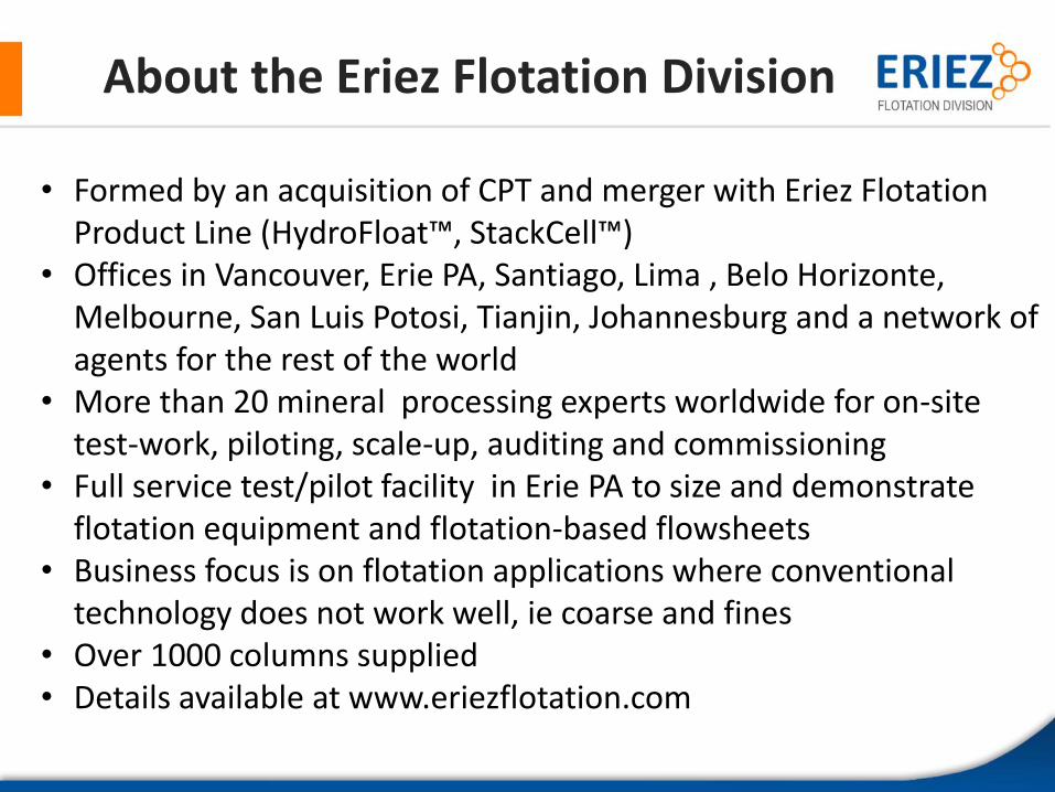
About the Eriez Flotation Division
3
• Formed by an acquisition of CPT and merger with Eriez Flotation Product Line (HydroFloat™, StackCell™)
• Offices in Vancouver, Erie PA, Santiago, Lima , Belo Horizonte, Melbourne, San Luis Potosi, Tianjin, Johannesburg and a network of agents for the rest of the world
• More than 20 mineral processing experts worldwide for on-site test-work, piloting, scale-up, auditing and commissioning
• Full service test/pilot facility in Erie PA to size and demonstrate flotation equipment and flotation-based flowsheets
• Business focus is on flotation applications where conventional technology does not work well, ie coarse and fines
• Over 1000 columns supplied• Details available at www.eriezflotation.com
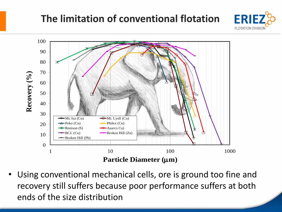
The limitation of conventional flotation
4
• Using conventional mechanical cells, ore is ground too fine and recovery still suffers because poor performance suffers at both ends of the size distribution
0
10
20
30
40
50
60
70
80
90
100
1 10 100 1000
Rec
over
y (%
)
Particle Diameter (m)
Mt. Isa (Cu) Mt. Lyell (Cu)
Peko (Cu) Philex (Cu)
Renison (S) Asarco Cu)
BCL (Cu) Broken Hill (Zn)
Broken Hill (Pb)
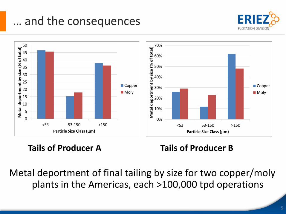
… and the consequences
Metal deportment of final tailing by size for two copper/moly plants in the Americas, each >100,000 tpd operations
5
Tails of Producer A Tails of Producer B
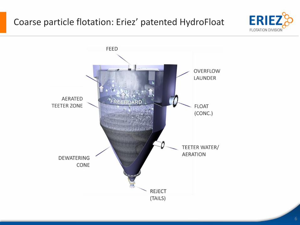
Coarse particle flotation: Eriez’ patented HydroFloat
6
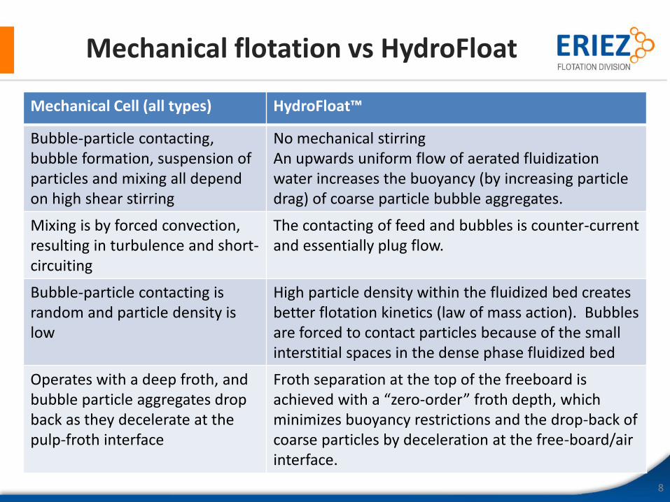
Mechanical flotation vs HydroFloat
8
Mechanical Cell (all types) HydroFloat™
Bubble-particle contacting, bubble formation, suspension of particles and mixing all depend on high shear stirring
No mechanical stirringAn upwards uniform flow of aerated fluidization water increases the buoyancy (by increasing particle drag) of coarse particle bubble aggregates.
Mixing is by forced convection, resulting in turbulence and short-circuiting
The contacting of feed and bubbles is counter-current and essentially plug flow.
Bubble-particle contacting is random and particle density is low
High particle density within the fluidized bed creates better flotation kinetics (law of mass action). Bubbles are forced to contact particles because of the small interstitial spaces in the dense phase fluidized bed
Operates with a deep froth, and bubble particle aggregates drop back as they decelerate at the pulp-froth interface
Froth separation at the top of the freeboard is achieved with a “zero-order” froth depth, which minimizes buoyancy restrictions and the drop-back of coarse particles by deceleration at the free-board/air interface.
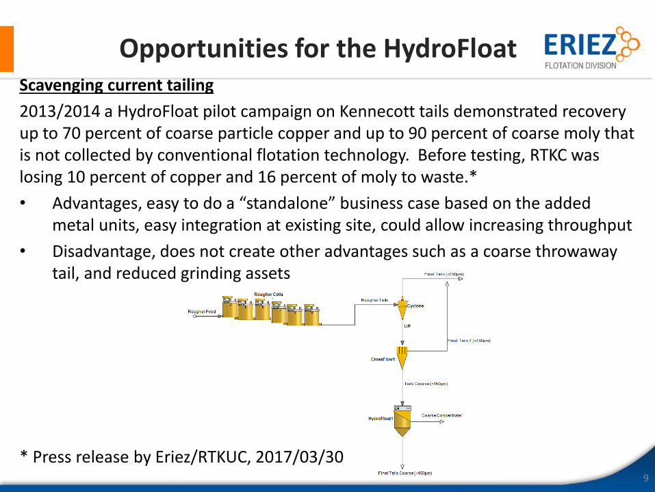
Opportunities for the HydroFloat
9
Scavenging current tailing
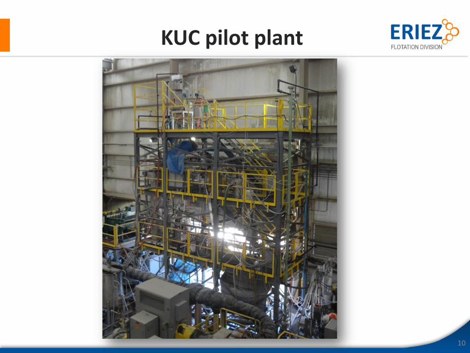
2013/2014 a HydroFloat pilot campaign on Kennecott tails demonstrated recoveryup to 70 percent of coarse particle copper and up to 90 percent of coarse moly that is not collected by conventional flotation technology. Before testing, RTKC was losing 10 percent of copper and 16 percent of moly to waste.*
• Advantages, easy to do a “standalone” business case based on the added metal units, easy integration at existing site, could allow increasing throughput
• Disadvantage, does not create other advantages such as a coarse throwaway tail, and reduced grinding assets
* Press release by Eriez/RTKUC, 2017/03/30
10
KUC pilot plant
Opportunities for the HydroFloat
11
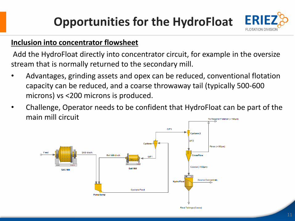
Inclusion into concentrator flowsheet
Add the HydroFloat directly into concentrator circuit, for example in the oversize stream that is normally returned to the secondary mill.
• Advantages, grinding assets and opex can be reduced, conventional flotation capacity can be reduced, and a coarse throwaway tail (typically 500-600 microns) vs <200 microns is produced.
• Challenge, Operator needs to be confident that HydroFloat can be part of the main mill circuit
A recent case study
12
• Polymetallic mine in Mexico
• Objective, consider benefits of coarse particle flotation in mill circuit vs in tailings scavenging
• Samples were taken from both streams and screened to remove minus 160 microns and plus 700 microns
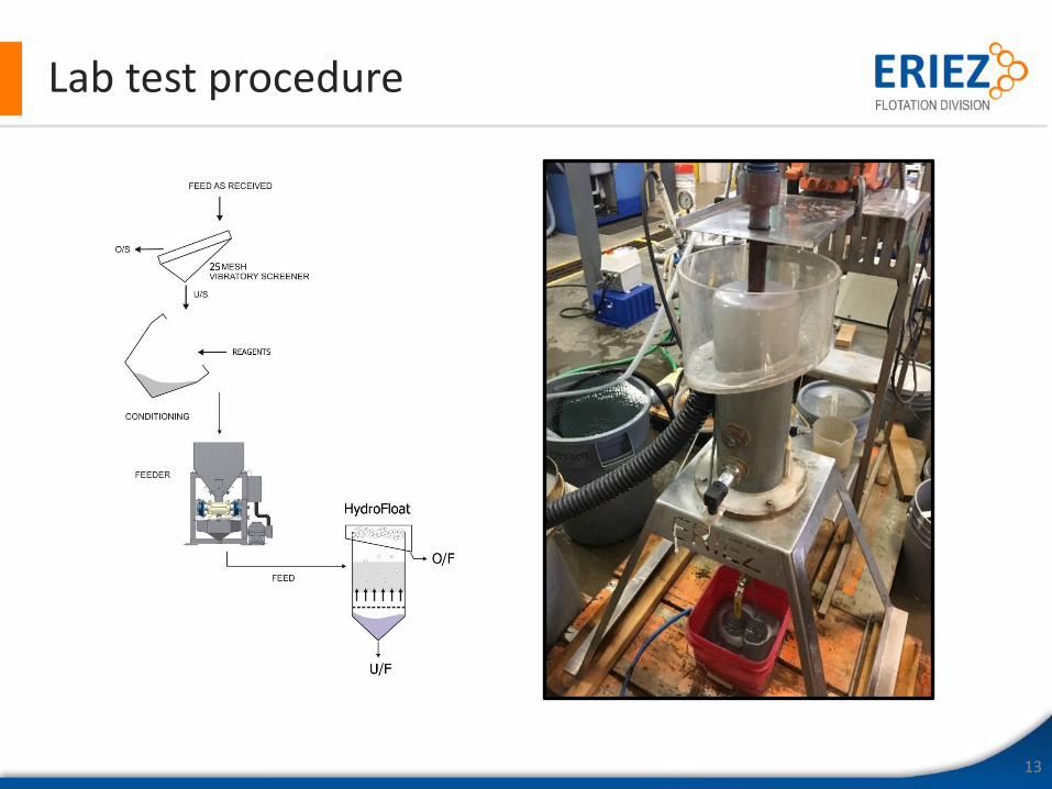
Lab test procedure
13
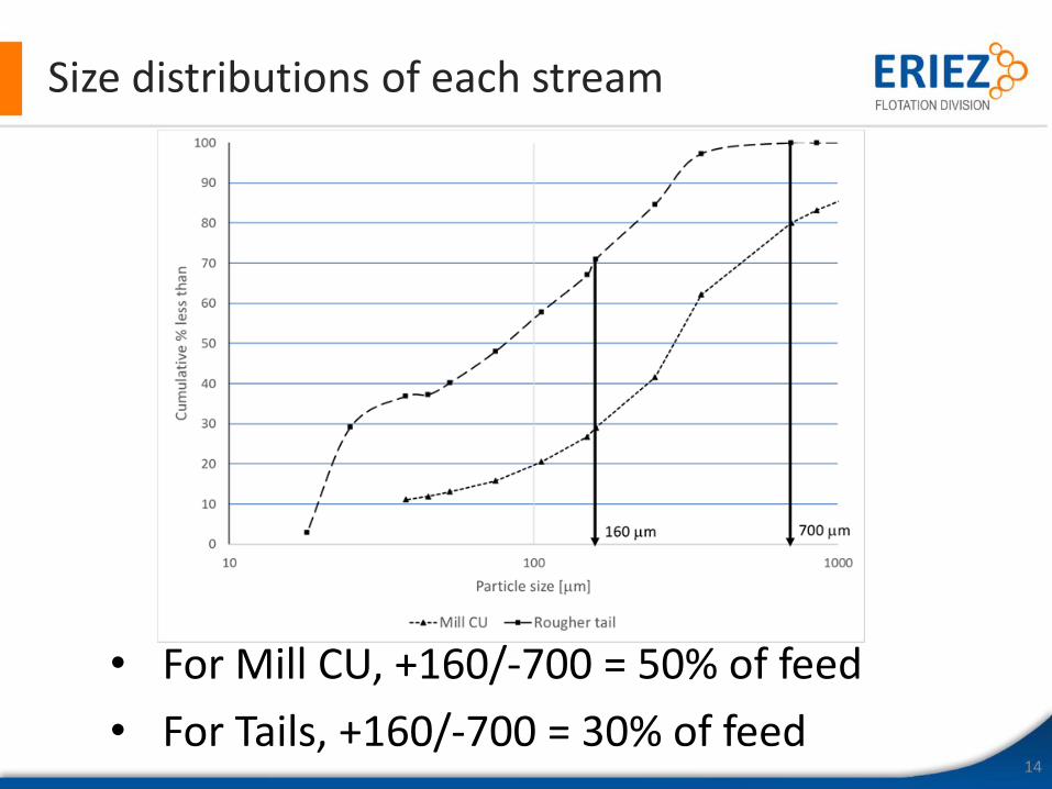
Size distributions of each stream
14
• For Mill CU, +160/-700 = 50% of feed
• For Tails, +160/-700 = 30% of feed
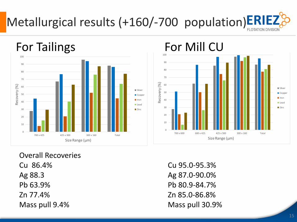
Metallurgical results (+160/-700 population)
15
0
10
20
30
40
50
60
70
80
90
100
700 x 425 425 x 300 300 x 160 Total
Rec
ove
ry (%
)
Size Range (µm)
Tailings HF Test - Size by Size Recovery
Silver
Copper
Iron
Lead
Zinc
0
10
20
30
40
50
60
70
80
90
100
700 x 600 600 x 425 425 x 300 300 x 160 Total
Rec
ove
ry (%
)
Size Range (µm)
Cyclone Underflow HF Test 2 - Size by Size Recovery
Silver
Copper
Iron
Lead
Zinc
For Tailings For Mill CU
Overall RecoveriesCu 86.4% Cu 95.0-95.3%Ag 88.3 Ag 87.0-90.0% Pb 63.9% Pb 80.9-84.7%Zn 77.4% Zn 85.0-86.8%Mass pull 9.4% Mass pull 30.9%
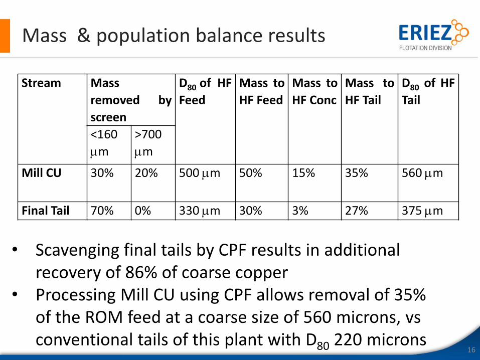
Mass & population balance results
16
Stream Mass
removed by
screen
D80 of HF
Feed
Mass to
HF Feed
Mass to
HF Conc
Mass to
HF Tail
D80 of HF
Tail
<160
m
>700
m
Mill CU 30% 20% 500 m 50% 15% 35% 560 m
Final Tail 70% 0% 330 m 30% 3% 27% 375 m
• Scavenging final tails by CPF results in additional recovery of 86% of coarse copper
• Processing Mill CU using CPF allows removal of 35% of the ROM feed at a coarse size of 560 microns, vs conventional tails of this plant with D80 220 microns
Conclusions
17
• Coarse particle flotation based on Eriez’ HydroFloat™ technology will greatly improve industrial flotation efficiencies and yields.
• There are a number of places in the concentrator flowsheet where this technology can be added.
• A number of leading mining companies are doing test-work, trade-off studies and pilot scale demonstrations to optimize the benefits
• CPF technology is being considered alongside fine particle flotation technology, to improve the other side of the elephant curve