Hydrocarbon Refrigerants Guidelines
36
Guidelines for the use of Hydrocarbon Refrigerants in Static Refrigeration and Air Conditioning Systems from A A C C R R I I B B
description
Refrigerants
Transcript of Hydrocarbon Refrigerants Guidelines

Guidelinesfor the use of
Hydrocarbon Refrigerantsin
Static Refrigeration andAir Conditioning Systems
from
AACCRRIIBB

1
Guidelines for the use of Hydrocarbon Refrigerants in Static Refrigeration and AirConditioning Systems
Foreword
With the introduction of the revised EU Ozone Depleting Substances Regulation inOctober 2000 and the introduction of a Climate Change Policy by the UK Government inNovember 2000, it is considered likely that more refrigeration system designers and userswill be turning to alternative refrigerants such as hydrocarbons. The increasedapplication of this technology will bring with it many technical and safety issues.People working in this industry have relatively little practical or theoretical knowledgeabout hydrocarbon refrigerants. It is therefore in the interests of the industry to makeavailable as much technical and safety information as possible. Much of the knowledgeand expertise already exists, and ACRIB has brought this together into a comprehensiveguide by reference to the range of detailed documentation available, as well as some ofthe basic information necessary for engineers working with refrigeration systems usinghydrocarbons.
This document is intended to highlight the differences between hydrocarbon refrigerantsand other refrigerants and to direct readers to the authoritative documents that should beconsulted.
There are suitable alternative refrigerants on the market today to replace many of thetraditional refrigerants which are in common use and, in some cases, are the onlyalternatives. However, the new generation of environmentally acceptable hydrocarbonproducts is gaining widespread acceptance for many applications, both commercial anddomestic. They do not pose any threat to the ozone layer and have a very low impact onglobal warming. The UK Government’s Climate Change policy has focused manypeople’s minds on global warming and its causes and, while the refrigeration and airconditioning industry is not a major contributor, hydrocarbons offer us the opportunity toreduce this contribution.
These environmental benefits do not however come without some costs. Hydrocarbonsare flammable and, if due diligence is not observed, safety could easily be compromised.Only engineers who are competent to use these gases should be allowed access to them toensure that the good name of the refrigeration and air conditioning industry ismaintained.
ACRIB supports and encourages change. The benefits of change will help to create abetter climate for our future and improve the quality of life for all.

2
CONTENTS
1.0 Refrigeration issues Page 31.1 Refrigerant selection Page 31.2 Refrigerant properties Page 41.3 Lubricants Page 41.4 Materials Page 51.5 General system components Page 5
2.0 Safety design and construction Page 72.1 General safety issues Page 72.2 Allowable refrigerant charge Page 72.3 Flammable properties of hydrocarbons Page 92.4 Safety standards and codes of practice Page 92.5 Design Page 102.6 Installation Page 142.7 Marking and Instructions Page 202.8 General considerations for workshop/manufacturing Page 21
3.0 Service, maintenance and refrigerant handling Page 233.1 Practical Competence Page 233.2 General approach to hydrocarbon refrigerant handling Page 233.3 Safety checks Page 243.4 Detection of hydrocarbon refrigerants Page 263.5 Breaking into a system and charging Page 273.6 Handling of cylinders Page 303.7 Transportation of cylinders Page 303.8 Storage of cylinders Page 313.9 Carriage of systems Page 31
4.0 References Page 33
3
1. REFRIGERATION ISSUES
Whilst the most notable aspects associated with hydrocarbon refrigeration system designare safety matters, general refrigeration issues should also be considered. These includethermodynamic properties, material compatibility and component selection.
1.1 Refrigerant selection
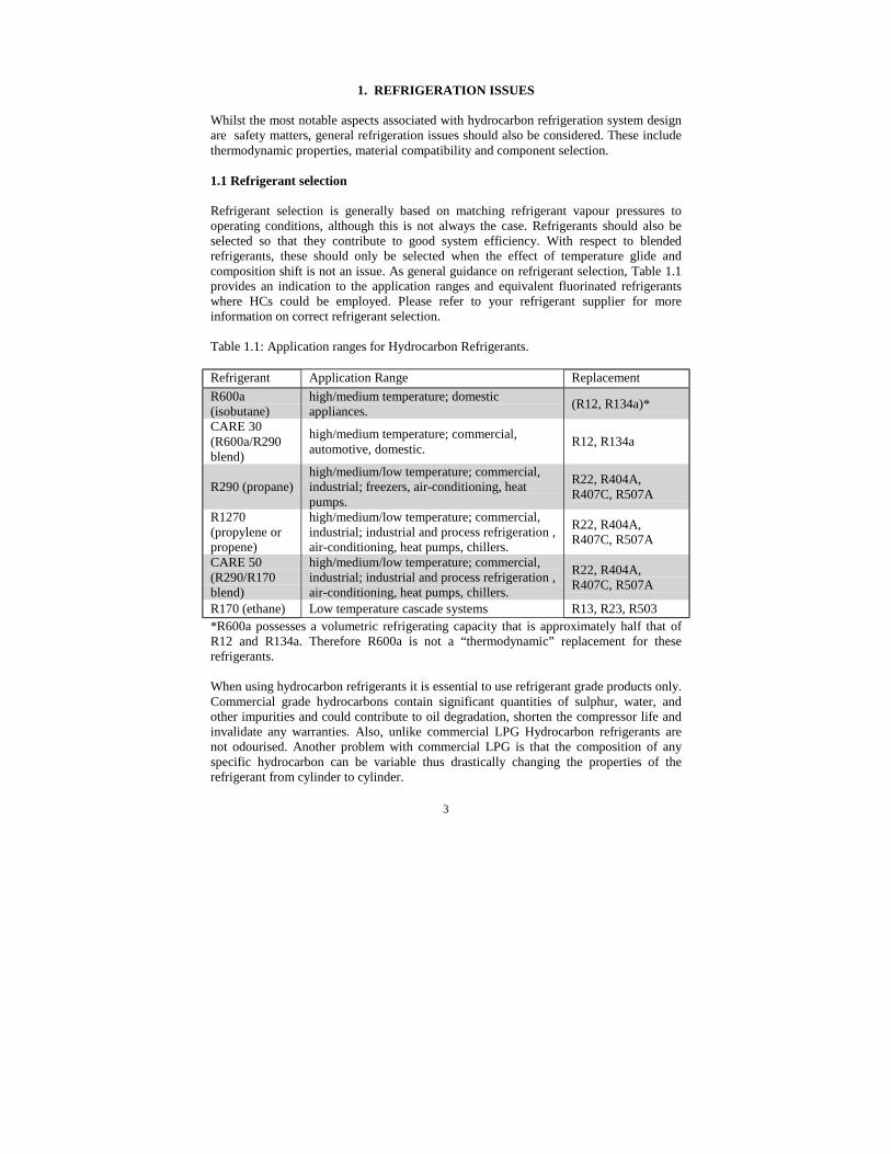
Refrigerant selection is generally based on matching refrigerant vapour pressures tooperating conditions, although this is not always the case. Refrigerants should also beselected so that they contribute to good system efficiency. With respect to blendedrefrigerants, these should only be selected when the effect of temperature glide andcomposition shift is not an issue. As general guidance on refrigerant selection, Table 1.1provides an indication to the application ranges and equivalent fluorinated refrigerantswhere HCs could be employed. Please refer to your refrigerant supplier for moreinformation on correct refrigerant selection.
Table 1.1: Application ranges for Hydrocarbon Refrigerants.
Refrigerant Application Range ReplacementR600a(isobutane)
high/medium temperature; domesticappliances. (R12, R134a)*
CARE 30(R600a/R290blend)
high/medium temperature; commercial,automotive, domestic. R12, R134a
R290 (propane)high/medium/low temperature; commercial,industrial; freezers, air-conditioning, heatpumps.
R22, R404A,R407C, R507A
R1270(propylene orpropene)
high/medium/low temperature; commercial,industrial; industrial and process refrigeration ,air-conditioning, heat pumps, chillers.
R22, R404A,R407C, R507A
CARE 50(R290/R170blend)
high/medium/low temperature; commercial,industrial; industrial and process refrigeration ,air-conditioning, heat pumps, chillers.
R22, R404A,R407C, R507A
R170 (ethane) Low temperature cascade systems R13, R23, R503*R600a possesses a volumetric refrigerating capacity that is approximately half that ofR12 and R134a. Therefore R600a is not a “thermodynamic” replacement for theserefrigerants.
When using hydrocarbon refrigerants it is essential to use refrigerant grade products only.Commercial grade hydrocarbons contain significant quantities of sulphur, water, andother impurities and could contribute to oil degradation, shorten the compressor life andinvalidate any warranties. Also, unlike commercial LPG Hydrocarbon refrigerants arenot odourised. Another problem with commercial LPG is that the composition of anyspecific hydrocarbon can be variable thus drastically changing the properties of therefrigerant from cylinder to cylinder.

4
1.2 Refrigerant properties
Refrigerant properties are necessary to describe the operating characteristics of therefrigerant within a system. In particular, physical properties of refrigerants are useful fordetermining the applicability of a refrigerant under design operating conditions.Thermodynamic and transport properties of refrigerants are necessary for predictingsystem behaviour and performance of components. Basic properties are provided inTable 1.2. For more comprehensive data the refrigerant supplier or reference texts shouldbe consulted.
Table 1.2: Physical Properties of Refrigerants
Refrigerant Mol. Mass(kg/kmol)
Normalboilingpt. at 1Atm.
Criticaltemp.(°C)
Criticalpressure
(bar, abs.)
Temp.glide at
25ºC (K)
Latent heatat 25ºC(kJ/kg)
Saturationpress at
25ºC (bar,abs.)
R600a 58.1 -11.7 135.0 36.45 0 332 3.5CARE30
51.0 -31.7 105.5 34.01 7.8 353 5.2
R290 44.1 -42.1 96.7 42.48 0 342 9.6R1270 42.1 -47.7 91.8 46.18 0 338 11.5CARE50
46.8 -49.1 79.3 33.86 3.9 348 10.1
R170 30.1 -88.8 32.2 48.91 0 299 24.0
1.3 Lubricants
Hydrocarbon refrigerants possess full chemical compatibility with nearly all lubricantscommonly used within refrigeration systems. Good miscibility is maintained with mostlubricants under all operating conditions. Due to the particularly good solubility withmineral oils, it may be necessary to use a lubricant with lower solubility or increasedviscosity to compensate for possible thinning under situations where high solubilitycould occur. Suppliers should be consulted for properties of oil/refrigerantcombinations.
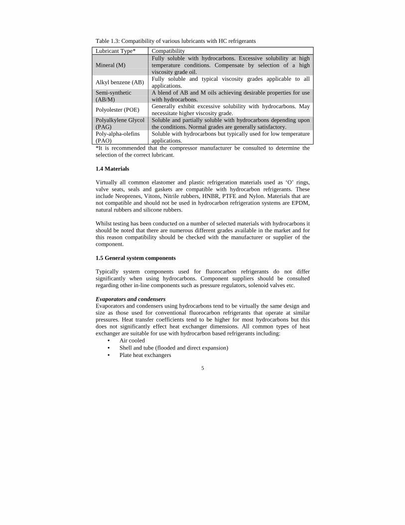
Lubricants containing silicone or silicate (often used as anti-foaming additives) are notcompatible with hydrocarbon refrigerants and should not be used. If changing orselecting a lubricant for a hydrocarbon refrigerant application, always consult thecompressor manufacturer as to their recommendations. Table 1.3 details the variouslubricants and their compatibility characteristics.
5
Table 1.3: Compatibility of various lubricants with HC refrigerants
Lubricant Type* Compatibility
Mineral (M)Fully soluble with hydrocarbons. Excessive solubility at hightemperature conditions. Compensate by selection of a highviscosity grade oil.
Alkyl benzene (AB) Fully soluble and typical viscosity grades applicable to allapplications.
Semi-synthetic(AB/M)
A blend of AB and M oils achieving desirable properties for usewith hydrocarbons.
Polyolester (POE) Generally exhibit excessive solubility with hydrocarbons. Maynecessitate higher viscosity grade.
Polyalkylene Glycol(PAG)
Soluble and partially soluble with hydrocarbons depending uponthe conditions. Normal grades are generally satisfactory.
Poly-alpha-olefins(PAO)
Soluble with hydrocarbons but typically used for low temperatureapplications.
*It is recommended that the compressor manufacturer be consulted to determine theselection of the correct lubricant.
1.4 Materials
Virtually all common elastomer and plastic refrigeration materials used as ‘O’ rings,valve seats, seals and gaskets are compatible with hydrocarbon refrigerants. Theseinclude Neoprenes, Vitons, Nitrile rubbers, HNBR, PTFE and Nylon. Materials that arenot compatible and should not be used in hydrocarbon refrigeration systems are EPDM,natural rubbers and silicone rubbers.
Whilst testing has been conducted on a number of selected materials with hydrocarbons itshould be noted that there are numerous different grades available in the market and forthis reason compatibility should be checked with the manufacturer or supplier of thecomponent.
1.5 General system components
Typically system components used for fluorocarbon refrigerants do not differsignificantly when using hydrocarbons. Component suppliers should be consultedregarding other in-line components such as pressure regulators, solenoid valves etc.
Evaporators and condensersEvaporators and condensers using hydrocarbons tend to be virtually the same design andsize as those used for conventional fluorocarbon refrigerants that operate at similarpressures. Heat transfer coefficients tend to be higher for most hydrocarbons but thisdoes not significantly effect heat exchanger dimensions. All common types of heatexchanger are suitable for use with hydrocarbon based refrigerants including:
• Air cooled• Shell and tube (flooded and direct expansion)• Plate heat exchangers

6
Suction-liquid heat exchangers should also be considered since they contribute toimproved system efficiency especially when using hydrocarbons
CompressorsMost compressor types are suitable for use with hydrocarbon refrigerants and compressorsuppliers should be consulted for application and selection. Using a compressor withhydrocarbons without the supplier's approval may invalidate the warranty.
In order to secure satisfactory performance, long life, and to protect the compressoragainst overload, certain design criteria should be observed. Compressor applicationnotes and data should always be consulted when designing a system. Ensurecompressors are clearly labelled to indicate that hydrocarbon refrigerants are being usedin the system. The use of crankcase heaters should be considered to avoid excessive oilsolubility.
Refrigerant Control DevicesAll expansion device types are suitable for use with hydrocarbon-based refrigerants andcomponent suppliers should be consulted for application and selection.
Design and selection criteria are the same as those for conventional fluorinatedrefrigerants. Capillary tube length is specific to each refrigerant. Computer programmesand tables are available for determining capillary tube size and length, although trial anderror is generally the preferred route. Thermostatic Expansion Valves (TEVs) forhydrocarbons are available from control suppliers. Alternatively TEVs for otherrefrigerants that operate with similar pressure-temperature relationships can be used.Electronic Expansion Valves (EEV) may also be used. EEV’s used in hydrocarbonsystems must conform to the requirements of electrical components as detailed in Section2.6.6.
DesiccantsDesiccants are used within filter dryers. Most commonly used desiccants are compatiblewith hydrocarbon refrigerants. Acceptable types are XH-5, XH-6 or equivalent.
Pipe size selectionWhen selecting refrigerant line sizes, specific hydrocarbon refrigerant pipe sizingliterature should be used. Despite most hydrocarbon refrigerants having similar operatingpressures to the “equivalent” fluorocarbon refrigerants, thermodynamic and transportproperties can differ significantly, thus data for other refrigerants will not be directlyapplicable. Refrigerant suppliers should provide the appropriate pipe size selection data.

7
2. SAFE SYSTEM DESIGN AND CONSTRUCTION
2.1 General Safety Issues
All hydrocarbon refrigerants are highly flammable but non-toxic. This gives them an“A3” classification according to BS EN378 Part 1. Reference should be made to thisStandard which details the requirements for the safe use of flammable refrigerants incommercial and industrial applications. For more detailed information on these safetyrequirements refer to the Institute of Refrigeration Safety Code for A3 refrigerants.
There are many other safety requirements that should be considered in the design andconstruction of all refrigerating and air conditioning installations, regardless of theflammability of the refrigerant used. General safety standards and codes of practice,referenced in this document, should be consulted for this additional information.
2.2 Allowable Refrigerant Charge
The limiting factor associated with the use of hydrocarbon refrigerants is the refrigerantcharge size, the occupancy category and the room size. The charge size requirementsaccording to Annex C of BS EN378 Part 1 are detailed in Table 2.14,7.
Table 2.1: Charge size requirements for various location categories
Category Examples RequirementsA(domestic/public)
Hospitals, prisons,theatres, schools,supermarkets, hotels,dwellings.
• <1.5kg per sealed system• <5kg in special machinery rooms or in
the open air for indirect systems
B(commercial/private)
Offices, small shops,restaurants, places forgeneral manufacturingand where peoplework.
• <2.5kg per sealed system• <10kg in special machinery rooms or
open air for indirect systems.
C(industrial/restricted)
Cold stores, dairies,abattoirs, non-publicareas of supermarkets,plant rooms.
• <10kg in human occupied spaces• <25kg if high pressure side (except air
cooled condenser) is located in a specialmachinery room or in the open air
• No limit if all refrigerant is contained ina special machinery room or in the openair.
Systems with charge sizes of 0.15kg or less can be installed in any size of room. Systemswith charge size of more than 0.15kg room size should be such that a sudden loss ofrefrigerant shall not raise the mean concentration in the room above the practical limit(approximately 0.008kg/m3). The general approach to safe design of systems containinghydrocarbon refrigerants is detailed in Figure 2.1. This flow chart provides general

8
guidance to the appropriate measures associated with a specific refrigerant charge sizeand the locations that they are permitted.
Figure 2.1 Flow chart indicating design routes according to safety standards.
Domestic appliance Occupancy category A Occupancy category B Occupancy category C
Safe electrics toSection 2.6.6
no
yes
No charge limit, or<25kg if high pressureside is remote (exceptair cooled condenser)
yes
no
Require Ex - typeelectrics
Mech. ventilation toSection 2.6.4 & leak
detection to 2.6.5
no
yes
yes
no
Max charge 10kg
Restrict access
Passconcentra-
tion testdefined inIEC60335-
2-24?
END
Chargemore than
2.5kg?
Locatedinside
Occupiedspace?
Condenser/ evaporatorfan airflow to eq.n. 2.3
Intended system location (Table 2.3)
Charge sizeless than
150g?
no
yes
Max charge according to eqn. 2.1 and Table 2.1Max charge 150g
9
2.3 Flammable Properties of Hydrocarbons
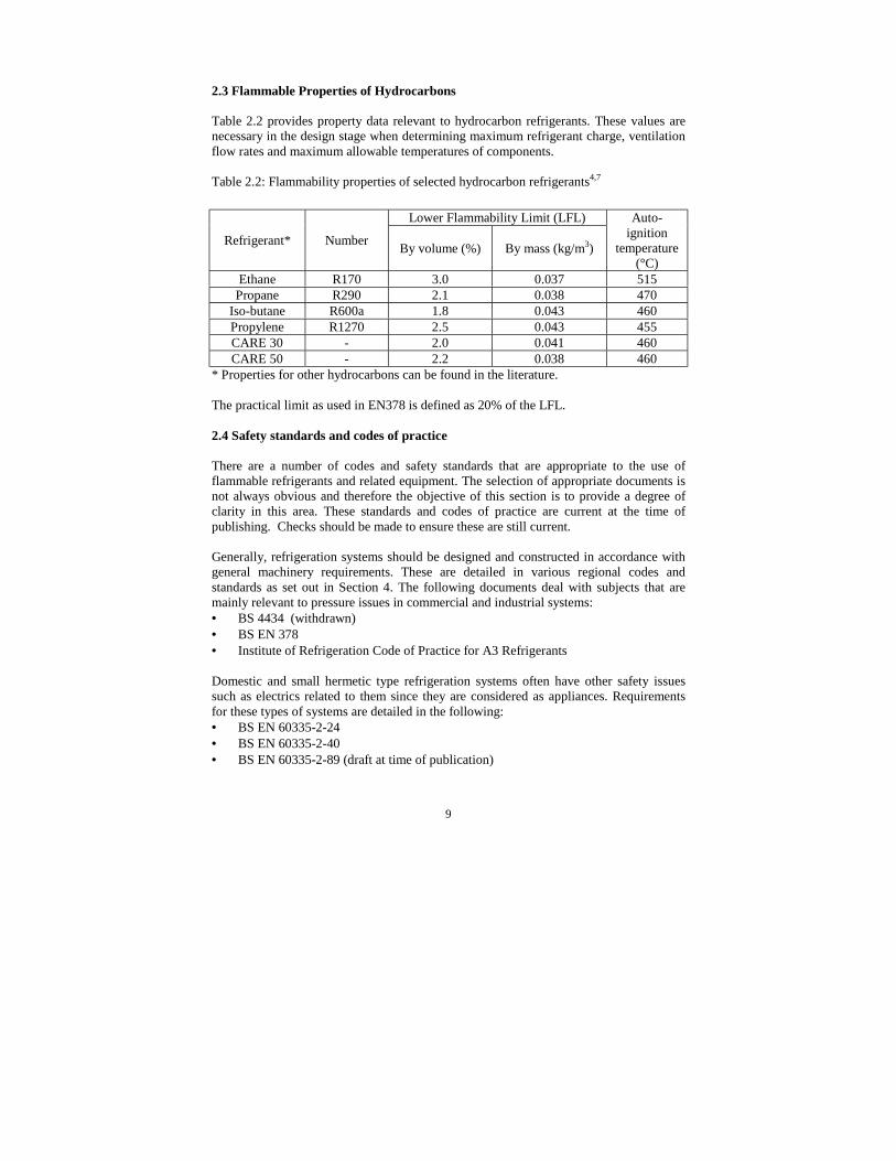
Table 2.2 provides property data relevant to hydrocarbon refrigerants. These values arenecessary in the design stage when determining maximum refrigerant charge, ventilationflow rates and maximum allowable temperatures of components.
Table 2.2: Flammability properties of selected hydrocarbon refrigerants4,7
Lower Flammability Limit (LFL)
Refrigerant* Number By volume (%) By mass (kg/m3)
Auto-ignition
temperature(°C)
Ethane R170 3.0 0.037 515Propane R290 2.1 0.038 470
Iso-butane R600a 1.8 0.043 460Propylene R1270 2.5 0.043 455CARE 30 - 2.0 0.041 460CARE 50 - 2.2 0.038 460
* Properties for other hydrocarbons can be found in the literature.
The practical limit as used in EN378 is defined as 20% of the LFL.
2.4 Safety standards and codes of practice
There are a number of codes and safety standards that are appropriate to the use offlammable refrigerants and related equipment. The selection of appropriate documents isnot always obvious and therefore the objective of this section is to provide a degree ofclarity in this area. These standards and codes of practice are current at the time ofpublishing. Checks should be made to ensure these are still current.
Generally, refrigeration systems should be designed and constructed in accordance withgeneral machinery requirements. These are detailed in various regional codes andstandards as set out in Section 4. The following documents deal with subjects that aremainly relevant to pressure issues in commercial and industrial systems:• BS 4434 (withdrawn)• BS EN 378• Institute of Refrigeration Code of Practice for A3 Refrigerants
Domestic and small hermetic type refrigeration systems often have other safety issuessuch as electrics related to them since they are considered as appliances. Requirementsfor these types of systems are detailed in the following:• BS EN 60335-2-24• BS EN 60335-2-40• BS EN 60335-2-89 (draft at time of publication)

10
BS EN 60335-2-24 applies to systems that use up to 150g of flammable refrigerants. Atthe time of publishing BS EN 60335-2-40 does not include requirements for flammablerefrigerants but is currently under revision. A new draft incorporating requirements forflammable refrigerants in air conditioners is available from British Standards Institution.
Regardless of the type of system, standards also exist for the refrigeration compressors:• pr EN 12693 (draft at time of publication)• BS EN 60335-2-34
Where very large quantities of flammable refrigerant are being employed, it isappropriate to consider standards that deal with hazardous areas. These standards areaimed directly at very large commercial and industrial type applications whereflammable materials are used and provide a general approach to risk assessment anddesign of such environments:• BS EN 1127-1
In particular, the most fundamental difference between systems using flammablerefrigerants and non-flammable refrigerants is the use of suitable electrical equipmentthat will not pose a risk in the event of a release. Whilst there are a range of differentmethodologies to deal with such electrical apparatus, the following standards provideinformation on the general approach for using electrical equipment in any potentiallyflammable areas:• IEC 60079-0• BS EN 60079-10• BS EN 60079-11• BS EN 60079-14• BS EN 60079-15
Finally, it is expected that engineers involved in the design, construction andmaintenance of refrigerating systems be competent. Competency in this context isdefined in a draft standard:• pr EN 13313 (draft at time of publication)
Standards are not exhaustive in their requirements and if a safe system of work candemonstrate an equal level of safety as that implied by the standard and satisfy UKlegislation, then this approach is equally acceptable. Indeed Notified Bodies often settheir own construction and test criteria where standards are not yet available or existingstandards are not considered appropriate for use.
2.5 Design
Specific design requirements are generally applied to a system based on the refrigerantcharge size and location. If manufacturer’s data is not available, charge sizes can beapproximated from internal system volumes and refrigerant densities based on designoperating temperatures. Below is an explanation of the rules governing equipmentdesign.
11
2.5.1 Refrigerant Charge
The equivalent hydrocarbon charge of a CFC or HCFC system will be approximately40% to 50% of the mass. Under no circumstances should the system be overcharged.Consult refrigerant suppliers for conversion data.
2.5.2 Categories
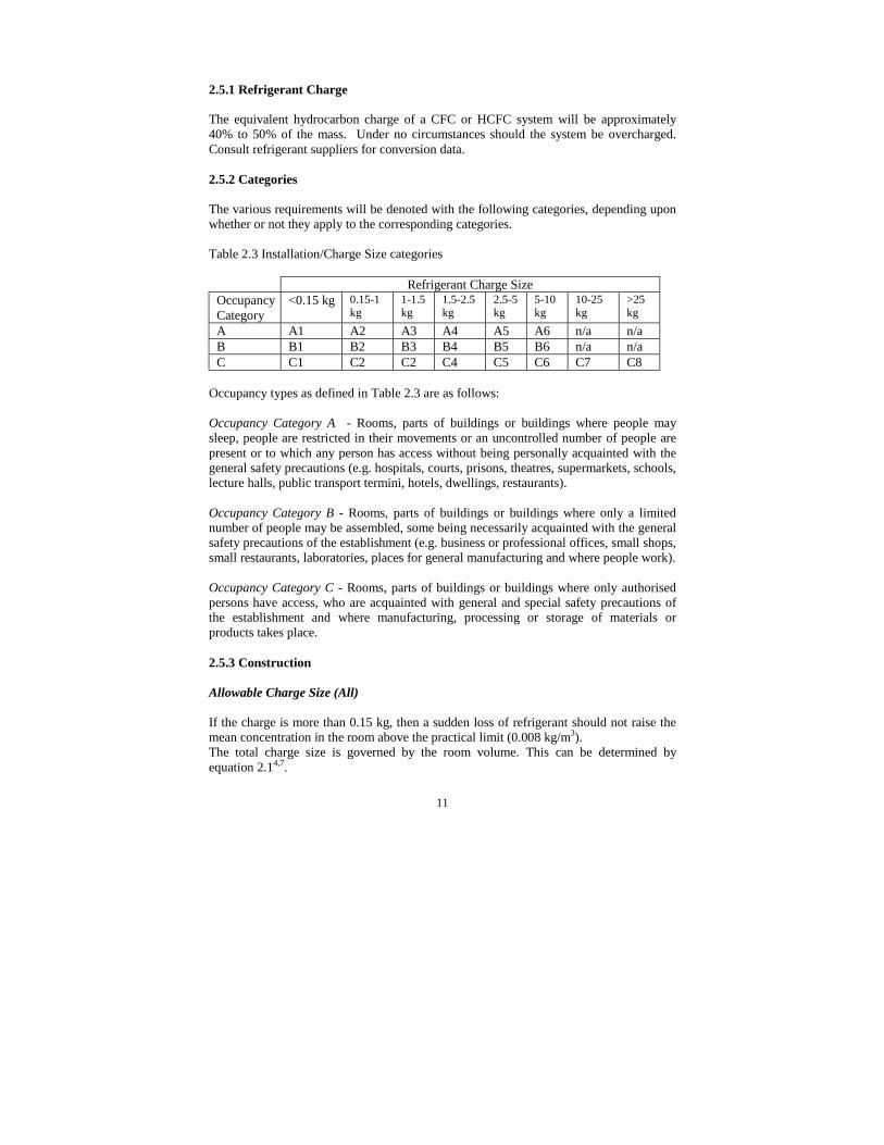
The various requirements will be denoted with the following categories, depending uponwhether or not they apply to the corresponding categories.
Table 2.3 Installation/Charge Size categories
Refrigerant Charge SizeOccupancyCategory
<0.15 kg 0.15-1kg
1-1.5kg
1.5-2.5kg
2.5-5kg
5-10kg
10-25kg
>25kg
A A1 A2 A3 A4 A5 A6 n/a n/aB B1 B2 B3 B4 B5 B6 n/a n/aC C1 C2 C2 C4 C5 C6 C7 C8
Occupancy types as defined in Table 2.3 are as follows:
Occupancy Category A - Rooms, parts of buildings or buildings where people maysleep, people are restricted in their movements or an uncontrolled number of people arepresent or to which any person has access without being personally acquainted with thegeneral safety precautions (e.g. hospitals, courts, prisons, theatres, supermarkets, schools,lecture halls, public transport termini, hotels, dwellings, restaurants).
Occupancy Category B - Rooms, parts of buildings or buildings where only a limitednumber of people may be assembled, some being necessarily acquainted with the generalsafety precautions of the establishment (e.g. business or professional offices, small shops,small restaurants, laboratories, places for general manufacturing and where people work).
Occupancy Category C - Rooms, parts of buildings or buildings where only authorisedpersons have access, who are acquainted with general and special safety precautions ofthe establishment and where manufacturing, processing or storage of materials orproducts takes place.
2.5.3 Construction
Allowable Charge Size (All)
If the charge is more than 0.15 kg, then a sudden loss of refrigerant should not raise themean concentration in the room above the practical limit (0.008 kg/m3).The total charge size is governed by the room volume. This can be determined byequation 2.14,7.

12
roomr VLFLM ⋅⋅= )(2.0 (Equation 2.1)Where:
rM = maximum allowable refrigerant charge per separate refrigerant circuit (kg)
roomV = room volume (m3)
LFL = Lower Flammability Limit of refrigerant (kg/m3) from Table 2.2
Similarly, the minimum room volume for a specific refrigerant charge is determined byequation 2.21,4.
)(2.0 LFLMV r
room ⋅= (Equation 2.2).
In practical terms, for a 100m3 of room volume, the maximum allowable charge wouldbe 800g of R290 per refrigerant circuit. Charges in systems below ground (i.e. cellars andbasements) are restricted to a maximum of 1.0kg even with larger room sizes. Sealedsystems containing a charge of less than 150g can be situated in any location, regardlessof room volume13,24.
Note that all charge limits apply per single refrigerant circuit, on the basis of probabilitythat two circuits will not have catastrophic failures simultaneously.
Avoidance of Stratification (All)
In the event of a “catastrophic” leak it is possible that stratification of refrigerant canoccur, resulting in the formation of flammable concentrations at low level. In order toprevent this from occurring the fan associated with the refrigerating system should beable to provide a minimum air flow, as detailed in equation 2.37. This only applies toequipment that contain refrigerant charges above 150g. The fan operates only during thecompressor on-cycle since the probability of a catastrophic leak during off-cycle isnegligible.
)(LFL
MCV rair ⋅=! (Equation 2.3)
Where:airV! = minimum air flow rate from the fan (m3/h)
The constant, C , depends upon the origin of the air flow:17=C , when the evaporator fan on an air conditioning unit is providing the air flow
into the room, or,20=C when the condenser fan on a refrigerating unit is providing the air flow into the
room.
The different constants result from the effectiveness of fan mixing, primarily due to thevelocity of the discharged air.

13
Maximum Refrigerant Charge (All)
The maximum allowable refrigerant charge for specific installation types, subject to otherrequirements are as follows:-• Direct expansion systems in a human occupied space is limited to A1-A3, B1-B4
and C1-C6.• Indirect systems in a human occupied space will be limited to A1-A5, B1-B6 and
C1-C6.• Systems with high pressure side (but not air cooled condenser) in a machinery room
will be limited to A1-A5, B1-B6 and C1-C7.• Systems with all refrigerants containing parts in a machinery room or in open air
shall be limited to A1-A5, B1-B6 and C1-C8.
Type of System (A4, A5, B6, C6)
The size of refrigerant charge can only be used within an indirect type refrigeratingsystem.
Combustible Materials (All)
Materials used to construct the refrigerating system should not be combustible.
2.5.4 Use of Components
Pressure Relief (A3-5, B3-B6, C3-C8)
These systems must use some type of pressure relief device but not only a fusible plug.
The discharge capacity of a pressure relief device shall be established in accordance withpr EN 12284.
It is preferable to use an automatic pressure relief valve on the high side, vented to thelow side before other pressure relief/bursting disc devices discharge refrigerant to theatmosphere.
Pressure Switches (A3-A5, B3-B6, C3-C8)
These systems must use low and high pressure switches located on the suction anddischarge sections of the system.
Vibration Elimination (All)
If the equipment is solidly mounted then vibration eliminators to the suction anddischarge lines should not under normal circumstances be required. If the compressor ismounted on rubber or spring mounts it may be advisable to install vibration eliminatorsto the suction and discharge line.
14
Pipe Connections (All)
Eliminate flared connections or compression fittings wherever possible. Use brazedjoints only.
Charging (A4, A5, B4-B6, C4-C8)
Where reasonably practicable, charging points for systems shall be in the open air.Where this is not practicable they shall not be sited near exit passageways.
Other System Components (All)
Other system mechanical components such as pressure vessels, compressors, heatexchangers, piping and fittings should conform to the requirements of the relevantstandards.
2.6 Installation
2.6.1 General
Minimum Room Volume (All)
Systems, or part of a system should not be located within a space or room where itsvolume is such that an entire refrigerant leak would cause a refrigerant/air mixture of aconcentration higher than one-fifth of the Lower Flammability Limit (LFL) of therefrigerant (equation 2.2). If this is not possible and the installation is in a machineryroom then the use of a refrigerant leak detector and mechanical ventilation should beemployed. (See section 2.6.3, 2.6.4 and 2.6.5).
Floor Voids (All)
If equipment that could release its charge is installed in a room with a floor void, certainprecautions should be taken. Where sources of ignition exist within the floor void, then itshould either be sealed or the space ventilated. In particular, precautions should be madeagainst refrigerant collecting in drains.
Maximum Charge Below Ground Level (A3-A5, B3-B6, C3-C8)
Refrigeration systems containing more than 1.0 kg should not be located in spaces belowground level. The allowable charge size method of calculation (equation 2.1) isparticularly applicable below ground level.
Location of Large Systems (A5, B6, C8)
These systems must be located out in the open air, or within a special machinery room.

15
Location of Systems in Hallways (A2-A5, B2-B6, C2-C8)
These systems should not be installed in hallways and lobbies.
Systems on Roofs (All)
In the case of installations on the roof of a building, precautions shall be taken to ensurethat in the event of a leak, refrigerant cannot enter the building.
2.6.2 Refrigeration Piping
Refrigerant Piping (A4, A5, B4-B6, C4-C8)
Systems with these charge sizes cannot have piping passing through rooms which do notcontain machinery as a part of the same refrigeration system. Where impractical thisrequirement can be overcome by using a sheath around the pipework, with each endvented to the rooms containing the refrigerating machinery or to the outside.
Piping Duct Services (All)
Piping ducts must not contain any other pipework or electrical wires or cables unlessprotection is provided to prevent damage due to interaction between services. Pipingthrough ducts shall not contain any mechanical connections or other line components.Any ducts through which refrigerant piping passes must be vented to the atmosphere.
Piping Through Walls, Floors, Ceiling and Roof Spaces (All)
Piping passing through fire resisting walls and ceilings shall be so sealed as not to allowspreading of fire to neighbouring rooms. Pipe ducts and shafts shall be shut off fromother rooms in such a way as to resist the spread of fire.
Piping through false ceilings is permitted provided that a false ceiling is not completelysealed.
Pipework Routing Arrangements
The route of the pipework between the evaporator and the condensing unit orcompressor, and remote condenser, should be as direct and as short a distance aspossible.
Water Circuits (All)
For systems using an indirect cooling circuit, there is a possibility of accidental release ofrefrigerant into the secondary circuit from a rupture of the evaporator or condenser wall.This should be dealt with by one of the following options:

16
• Incorporate an air vent/air separator within the secondary circuit, on the outlet pipefrom the evaporator or condenser. Ensure that it is adequately sized such that it willrelease any refrigerant back into the housing, machinery room, special area or to theoutside. Thus the release can then be dealt with as any normal refrigerant releasefrom the primary circuit.
• Use a 'double-walled' heat exchanger, of the type which is laser-welded, designedsuch that it can only vent to atmosphere rather than the secondary circuit in theevent of damage.
2.6.3 Machinery Rooms
Machinery rooms for systems using flammable refrigerants shall be designed to preventthe ignition of an explosive refrigerant/air mixture. There should be warning noticesstating that smoking, naked lights or flames are prohibited. Fire extinguishers should beused in accordance with local fire authorities.
Machinery rooms must not be constructed out of combustible materials. If it is possiblefor the concentration of refrigerant to reach the Lower Flammability Limit then someexplosion relief should be provided in the construction of the machinery room. This maybe in the form of movable panels or louvres.
Locate all refrigerant containing machinery so that damage from external sources wouldbe difficult.
NOTE: Although a machinery room does not necessarily serve exclusively forrefrigeration equipment, boilers and other open flame devices should not share the space.Air intakes for equipment should not be taken from within the machinery room, or closeto such machinery room ventilation outlet.
2.6.4 Ventilation
Refrigeration machinery rooms should be vented to the outside air by means of natural ormechanical ventilation.
Free Air Movement (All)
Ensure that free air movement can be achieved around all refrigerant containing parts ofthe system. Openings for outside air should be positioned such that short circuiting doesnot occur.
Mechanical Ventilation (All)
Where the refrigerant charge of a single refrigerating circuit exceeds the mass in equation2.1 a machinery room using hydrocarbons must employ mechanical ventilation capableof providing the minimum ventilation rate. The minimum ventilation rate depends uponthe type of electrical protection within the machinery room. Where the electrical
17
installation is protected according to Section 2.6.6 the mechanical ventilation rate shouldbe equivalent to at least 10 room volume changes per hour4.
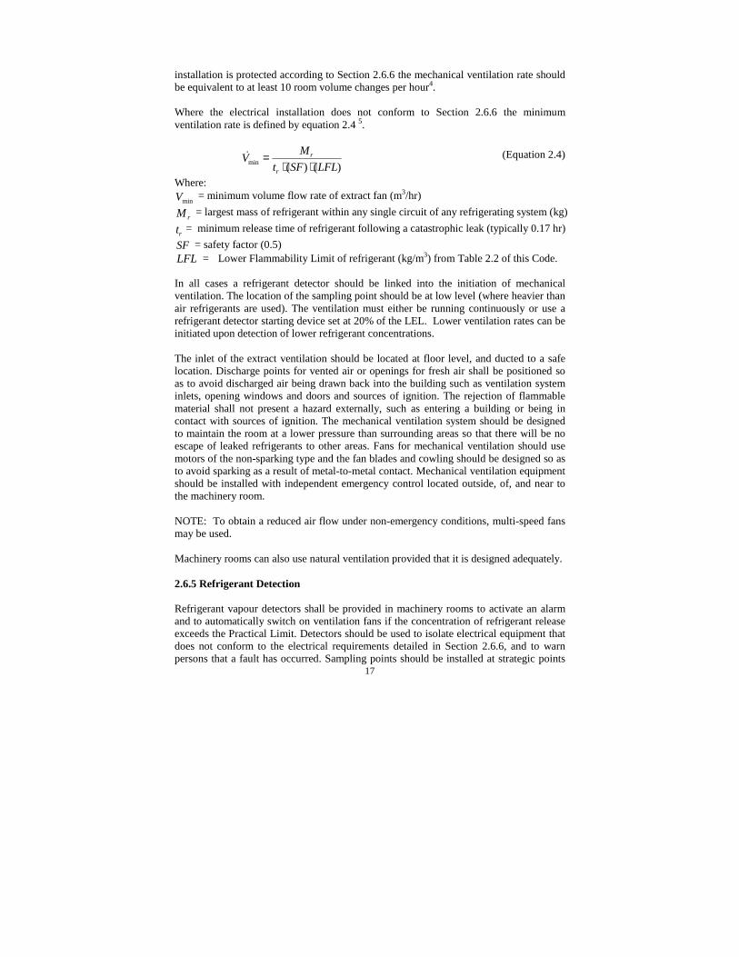
Where the electrical installation does not conform to Section 2.6.6 the minimumventilation rate is defined by equation 2.4 5.
)()(min LFLSFtMV
r
r
⋅⋅=! (Equation 2.4)
Where:minV = minimum volume flow rate of extract fan (m3/hr)
rM = largest mass of refrigerant within any single circuit of any refrigerating system (kg)
rt = minimum release time of refrigerant following a catastrophic leak (typically 0.17 hr)SF = safety factor (0.5)LFL = Lower Flammability Limit of refrigerant (kg/m3) from Table 2.2 of this Code.
In all cases a refrigerant detector should be linked into the initiation of mechanicalventilation. The location of the sampling point should be at low level (where heavier thanair refrigerants are used). The ventilation must either be running continuously or use arefrigerant detector starting device set at 20% of the LEL. Lower ventilation rates can beinitiated upon detection of lower refrigerant concentrations.
The inlet of the extract ventilation should be located at floor level, and ducted to a safelocation. Discharge points for vented air or openings for fresh air shall be positioned soas to avoid discharged air being drawn back into the building such as ventilation systeminlets, opening windows and doors and sources of ignition. The rejection of flammablematerial shall not present a hazard externally, such as entering a building or being incontact with sources of ignition. The mechanical ventilation system should be designedto maintain the room at a lower pressure than surrounding areas so that there will be noescape of leaked refrigerants to other areas. Fans for mechanical ventilation should usemotors of the non-sparking type and the fan blades and cowling should be designed so asto avoid sparking as a result of metal-to-metal contact. Mechanical ventilation equipmentshould be installed with independent emergency control located outside, of, and near tothe machinery room.
NOTE: To obtain a reduced air flow under non-emergency conditions, multi-speed fansmay be used.
Machinery rooms can also use natural ventilation provided that it is designed adequately.
2.6.5 Refrigerant Detection
Refrigerant vapour detectors shall be provided in machinery rooms to activate an alarmand to automatically switch on ventilation fans if the concentration of refrigerant releaseexceeds the Practical Limit. Detectors should be used to isolate electrical equipment thatdoes not conform to the electrical requirements detailed in Section 2.6.6, and to warnpersons that a fault has occurred. Sampling points should be installed at strategic points

18
within machinery rooms. Points should be located so that they provide rapid signals inthe event of a leak, and that the effect of air movement does not inhibit theireffectiveness. Refrigerant leak detectors shall be calibrated for the specific refrigerantthey are intended to detect. Where the refrigerant is heavier than air, sampling pointsshall be located at floor level. A detector can normally cover an area of about 36m2
provided it is mounted at floor level4.
Refrigerant Leak Detection (A4, A5, B4-B6, C4-C8)
If the concentration within the machine room can rise above the practical limit then arefrigerant leak detection device should be installed.
Refrigerant Detection Alarm (A4, A5, B4-B6, C4-C8)
When a leak of refrigerant is detected, the device shall initiate an alarm in the machineryroom and also elsewhere so that emergency action may be initiated. The alarm shall bein the form of an audible signal, a flashing light or both.
Detectors should be used to isolate electrical equipment that does not conform to therequirements for electrical equipment in section 2.6.6, and to initiate mechanicalventilation and to warn persons that a fault has occurred.
2.6.6 Sources of Ignition
There should be no sources of ignition as part of the refrigerating system or equipment.
Electrical Components (All)
Precautions should be taken to avoid the possibility of direct sources of ignition fromexposed electrical contacts. Electrical items that have the potential to produce electricalsparks during normal operation should receive particular attention to eliminate them aspotential sources of ignition. The following methods can be applied:
• Insulate terminals• Locate within IP65 enclosure• Replace with solid state type component• Replace with Ex type component• Locate externally
Providing such items only comprise of solid state parts or have casings which are solidencapsulated or otherwise sealed to at least IP54 or are located externally to the casing ofthe refrigerant containing parts then adequate precautions as required above are normallyachieved.
NOTE: For manufactured appliances rather than installed equipment, an alternativeoption exists. For systems containing less than 150g of refrigerant a leakage test fromthe refrigeration circuit can be conducted to determine whether sufficient refrigerant

19
reaches the components to present a hazardous situation 13,24. This test should beconducted under controlled conditions.
Care should be taken to ensure that electrical terminations, including capacitorterminations are adequately tightened and secured against loosening and that adequateinsulation is provided to avoid live parts shorting together.
Motors, including fans, pumps and compressors should be of brushless design.
Components to consider as possible sources of ignition are:
On/off manual switches Liquid level switch Condensate pump switchThermostats Flow switches Fan speed controllersPressure switches Start relays Humidity controllersOil differential switches Thermal overload relays Programmable controllersFan delay switches Potential relays Defrost timers/switchesContactors Universal relays Time switches/relaysIsolator switches
NOTE: This list is not exhaustive.
Ex-rated components (A5, A6, B5, B6, C5-C8)
If the refrigerant charge exceeds 2.5kg in any one refrigerant circuit then the selection ofelectrical apparatus and its installation should be in accordance with BS EN 60079. Forexample, Ex rated components can be used.
NOTE: In machinery rooms it is sufficient to fit leak detection equipment which isolatesall plant room electrics via a contactor, upon detection of refrigerant. The detectiondevice should also initiate ventilation with an appropriate extract system from a separatededicated power supply.
Hot Surfaces (All)
Parts of refrigerating machines whose surfaces could become excessively hot shall beavoided. All components that could come into contact with released refrigerant shallhave a maximum surface temperature not higher than 100K below the auto-ignitiontemperature of the refrigerant used. Auto-ignition temperature for various refrigerantsare provided in Table 2.2.
2.6.7 Pipework Installation
The following should be installed in accordance with the BRA Guide to GoodRefrigeration Practice, and BRA jointing of Copper Pipework for Refrigeration Systems:• Copper Tubing• Copper to Copper Pipework Fittings• Swaged Joint

20
• Installation of Line Components• Pipework Support Methods for Copper Pipework• Methods for Cutting Tube• Tube Bending• Brazing of Pipework
2.7 Marking and Instructions
Marking of Systems Installed on Site (All)
Safety instructions relating to the refrigerant in use shall be predominately displayed inmachinery rooms. Refrigerating systems installed on site shall be provided with a clearlyvisible plate giving at least the following information:-• The installers name and address.• The year of installation.• The refrigerant type and number.• The allowable pressures for the systems.• The approximate refrigerant charge.
Marking of Compressors and Unit Systems (All)
Each unit system and compressor shall be provided with a permanently connected plategiving at least the following:-• Manufacturer or vendors name.• Model or type reference.• Serial number.• Refrigerant for which it is designed (for unit systems only).• System charge weight of refrigerant.• Test pressure and allowable pressure (not for domestic refrigeration).
Marking of Pipes (All)
Pipes shall be marked, preferably according to a suitable code, e.g. a colour code, toindicate the substance flowing through them.
'Flammable Gas' Stickers (All)
All systems should have at least two hydrocarbon 'flammable refrigerant' stickers placedon them before commissioning. The stickers should be located on the compressor,receiver and any other part of the system to which an engineer would have access to therefrigerant.
Instructions (All)
The supplier or manufacturer shall provide at least one copy of a leaflet or instructionmanual containing at least the following information:

21
• Name, address and telephone number of the manufacturer.• Name, address and telephone number for customer service, if different from item
above.• Full instructions for the operation, maintenance and servicing of the system and its
components, including:(a) A description of the system and its components, its functioning and its purpose,
including a refrigerating system schematic diagram and electrical circuitdiagram.
(b) Procedure for normal starting and stopping of the system.(c) Procedure for stopping the system in an emergency.(d) Causes of possible faults and appropriate methods of repair.(e) Proposals for planned maintenance including leak testing.(f) Reference to the requirements of charging the refrigerant.(g) A warning against the charging with the incorrect refrigerant.(h) Precautions relating to the storage of supplementary refrigerant in a machinery
room.(i) The refrigerant to be used and a warning that substitution of another refrigerant
should not be made without the approval of a competent person.(j) Precautions to be made to prevent freezing in heat exchangers.(k) The functions, routine testing and maintenance of all safety and alarms.(l) Procedures to be followed in the event of emergencies and/or injuries to
persons.(m) Details of any necessary protective equipment.
• Warning notes:-(a) Warning - keep ventilation openings in the appliance enclosure or in the
structure clear of obstruction.(b) Warning - do not use mechanical devices or other means to accelerate the
defrosting process, other than those recommended by the manufacturer.
2.8 General considerations for workshop/manufacturing
Production areas within factories and workshops require additional precautions inaddition to those detailed in other sections. Whilst the scope of this publication does notallow for detailed coverage of these requirements, the following lists items that should beconsidered.
• Storage and handling of hydrocarbon refrigerant cylinders(a) General requirements(b) Open air storage(c) Storage within specially designed buildings and outhouses(d) Storage within parts of a building
• Bulk storage installations(a) Location, separation and security requirements(b) Underground and mounded vessels(c) Fittings and piping

22
(d) Fire precautions
• Appliance charging areas(a) General requirements(b) Factory - bay area(c) Factory – production line
• Electrical requirements
• Safety Management
A comprehensive risk assessment should be conducted prior to installation. Documentsrelating to the areas detailed above can be obtained from the Liquified Petroleum GasAssociation (LPGA) and from standards dealing with hazardous areas. Additional furtherinformation and appropriate codes can be obtained from the refrigerant supplier.

23
3. SERVICE, MAINTENANCE AND REFRIGERANT HANDLING
This Section deals with practical aspects relating to the handling of both the hydrocarbonrefrigeration machine and the hydrocarbon refrigerant itself. It is recommended thatcompanies who use hydrocarbon refrigerants either in equipment they manufacture orequipment for which they are responsible, put into place a general strategy to ensure thatcorrect work practices are employed.
Note that the requirements detailed under Section 3 are not exhaustive, but are intendedas a comprehensive guide only. Additional precautions may be appropriate dependentupon the particular equipment and conditions.
3.1 Practical Competence
Any person who is involved with working on or breaking into a refrigerant circuit shouldhold a current valid certificate from an industry accredited assessment authority, whichauthorises their competence to handle refrigerants (including hydrocarbons) safely inaccordance with an industry recognised assessment specification.
Servicing shall only be performed as recommended by the equipment manufacturer.Maintenance and repair requiring the assistance of other skilled personnel shall be carriedout under the supervision of the person competent in the use of flammable refrigerants.
Refer to the draft European Standard prEN 13313.
3.2 General Approach to Hydrocarbon Refrigerant Handling
All flammable refrigerant gases when mixed with air form a flammable mixture. The effectof ignition of such a mixture can be severe. It is therefore important that the appropriatesafety requirements are observed at all times when working with flammable refrigerants.
Any equipment used in the process of repair must be suitable for use with flammablerefrigerants. All tools and equipment (including measuring equipment) are to be checkedfor suitability for working on the equipment, particular attention is to be paid to theselection of:
• Refrigerant recovery units.• Refrigerant leak testing units• Electrical test meters• Refrigerant recovery cylinders• Portable lighting
If the installation permits, it is recommended that the equipment be removed from itsexisting position to a controlled workshop environment suitable for the type of repairwhere work can be conducted safely.

24
3.3 Safety checks
3.3.1 Checks to the area
Prior to beginning work on systems containing hydrocarbon refrigerants, safety checksare necessary to ensure that the risk of ignition is minimised. For repair to therefrigerating system prior to conducting work on the system, the following precautionsshall be complied with:
Work procedureWork shall be undertaken under a controlled procedure so as to minimise the risk of aflammable gas or vapour being present while the work is being performed.
General work areaAll maintenance staff and others working in the local area should be instructed as to thenature of work being carried out. Work in confined spaces must be avoided. The areaaround the workspace is to be sectioned off. Ensure that the conditions within the areahave been made safe by control of flammable material
Checking for presence of refrigerantThe area shall be checked with an appropriate refrigerant detector prior to and duringwork to ensure the technician is aware of potentially flammable atmospheres. Ensure thatthe leak detection equipment being used is suitable for use with flammable refrigerants,i.e. non-sparking, adequately sealed or intrinsically safe (see section 3.4).
Presence of fire extinguisherIf any hot work is to be conducted on the refrigeration equipment or any associated parts,appropriate fire extinguishing equipment shall be available to hand. Have a dry powderor CO2 fire extinguisher adjacent to the charging area.
No ignition sourcesNo person carrying out work in relation to a refrigeration system which involvesexposing any pipe work which contains or has contained flammable refrigerant shall useany sources of ignition in such a manner that it may lead to the risk of fire or explosion.All possible ignition sources, including cigarette smoking, should be sufficiently faraway from the site of installation, repairing, removing and disposal during whichflammable refrigerant can possibly be released to surrounding space. Should there be aneed for brazing or welding to be undertaken refer to section 3.5.1. Prior to work takingplace, the area around the equipment is to be surveyed to establish any flammablehazards or ignition risks. Display 'No Smoking' signs.
Ventilated areaEnsure that the area is in the open or that it is adequately ventilated before breaking intothe system or conducting any hot work. A degree of ventilation should continue duringthe period that the work is carried out. The ventilation should safely disperse any releasedrefrigerant and preferably expel it externally to the atmosphere.

25
3.3.2 Checks to the refrigeration equipment
Where electrical components are being changed, they are to be “fit for purpose”, and tothe correct specification. At all times the manufacturers maintenance and serviceguidelines are to be followed. If in doubt consult the manufacturers TechnicalDepartment for assistance.
The following checks should be applied to installations using flammable refrigerants:• That the charge size is in accordance with the room size within which the refrigerant
containing parts are installed, according to section 2.5.3. (Note that hydrocarboncharge sizes are typically 40% to 50% of CFC, HCFC and HFC charge sizes)
• That ventilation machinery and outlets are operating adequately and not obstructed,according to section 2.6.4.
• Confirm operation of equipment such as refrigerant leak detectors and mechanicalventilation systems.
• If an indirect refrigerating circuit is being used, the secondary circuit should bechecked for the presence of refrigerant.
• Ensure that marking to the equipment continues to be visible and legible. Markingand signs that are worn should be corrected (see section 2.7).
• Refrigeration pipe or components are not installed in a position where it is likely tobe exposed to any substance which may corrode refrigerant containing components,unless the components are constructed of materials which are inherently resistant tobeing corroded or are suitably protected against being so corroded.
The engineer is referred to the requirements for the installation of equipment in Section 2of this guide.
3.3.3 Checks to electrical devices
Repair and maintenance to electrical components shall include initial safety checks andcomponent inspection procedures. If a fault exists that could compromise safety, then noelectrical supply should be connected to the circuit until it is satisfactorily dealt with. Ifthe fault cannot be corrected immediately but it is necessary to continue operation, anadequate temporary solution shall be used, but this must be reported to the owner of theequipment so all parties are aware.
Initial safety checks should be as follows:• Capacitors are discharged. This should be done in a safe manner to avoid possibility
of sparking.• Do not work on “live” electrical components and wiring whilst charging, recovering
or purging the system.• Continuity of earth bonding.
During repairs to sealed components, all electrical supplies must be disconnected fromthe equipment being worked upon prior to any removal of sealed covers, etc. If it isabsolutely necessary to have an electrical supply to equipment during servicing, then a
26
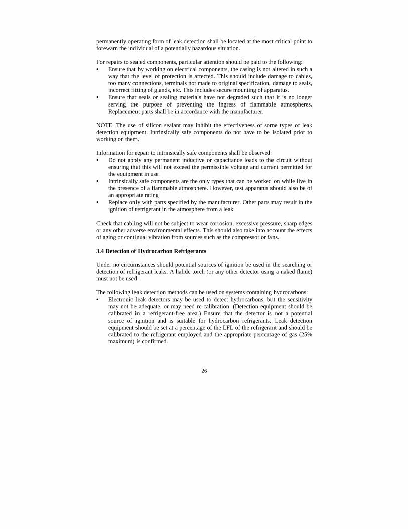
permanently operating form of leak detection shall be located at the most critical point toforewarn the individual of a potentially hazardous situation.
For repairs to sealed components, particular attention should be paid to the following:• Ensure that by working on electrical components, the casing is not altered in such a
way that the level of protection is affected. This should include damage to cables,too many connections, terminals not made to original specification, damage to seals,incorrect fitting of glands, etc. This includes secure mounting of apparatus.
• Ensure that seals or sealing materials have not degraded such that it is no longerserving the purpose of preventing the ingress of flammable atmospheres.Replacement parts shall be in accordance with the manufacturer.
NOTE. The use of silicon sealant may inhibit the effectiveness of some types of leakdetection equipment. Intrinsically safe components do not have to be isolated prior toworking on them.
Information for repair to intrinsically safe components shall be observed:• Do not apply any permanent inductive or capacitance loads to the circuit without
ensuring that this will not exceed the permissible voltage and current permitted forthe equipment in use
• Intrinsically safe components are the only types that can be worked on while live inthe presence of a flammable atmosphere. However, test apparatus should also be ofan appropriate rating
• Replace only with parts specified by the manufacturer. Other parts may result in theignition of refrigerant in the atmosphere from a leak
Check that cabling will not be subject to wear corrosion, excessive pressure, sharp edgesor any other adverse environmental effects. This should also take into account the effectsof aging or continual vibration from sources such as the compressor or fans.
3.4 Detection of Hydrocarbon Refrigerants
Under no circumstances should potential sources of ignition be used in the searching ordetection of refrigerant leaks. A halide torch (or any other detector using a naked flame)must not be used.
The following leak detection methods can be used on systems containing hydrocarbons:• Electronic leak detectors may be used to detect hydrocarbons, but the sensitivity
may not be adequate, or may need re-calibration. (Detection equipment should becalibrated in a refrigerant-free area.) Ensure that the detector is not a potentialsource of ignition and is suitable for hydrocarbon refrigerants. Leak detectionequipment should be set at a percentage of the LFL of the refrigerant and should becalibrated to the refrigerant employed and the appropriate percentage of gas (25%maximum) is confirmed.

27
• Leak detection fluids are suitable for use with hydrocarbon refrigerants but the useof detergents containing chlorine should be avoided as the chlorine may react withthe refrigerant and corrode the copper pipework.
• Oil additives such as those used in fluorescent leak detection systems will operatewith hydrocarbons.
• If a leak is suspected from a hydrocarbon refrigerant system all naked flames shouldbe removed/extinguished.
If a leakage of refrigerant is found which requires brazing, all of the refrigerant shall berecovered from the system, or isolated (by means of shut off valves) in a part of thesystem remote from the leak. Oxygen Free Nitrogen (OFN) should then be purgedthrough the system both before and during the brazing process.
3.5 Breaking into a System and Charging
3.5.1 Removal and evacuation
When breaking into the refrigerant circuit to make repairs - or for any other purpose -conventional procedures are used. However, it is important that best practice is followedsince flammability is now a consideration. The following procedure shall be adhered to:
• remove refrigerant• purge the circuit with inert gas• evacuate• purge again with inert gas• open the circuit by cutting or brazing,
The refrigerant charge should be recovered into the correct recovery cylinders, thesystem is then to be “flushed” with OFN to render the unit safe, this process may need tobe repeated several times. On no account use compressed air or oxygen for this task.
Flushing is achieved by breaking the vacuum in the system with OFN and continuing tofill until the working pressure is achieved, then venting to atmosphere, and finally pullingdown to a vacuum. This process is repeated until satisfied that no hydrocarbons arewithin the system. When the final OFN charge is used, the system can be vented down toatmospheric pressure to enable work to take place. This operation is absolutely vital ifbrazing operations on the pipework are to take place.
Ensure that the outlet for the vacuum pump is not close to any ignition sources and thereis ventilation available.
3.5.2 Charging
The charging of refrigeration systems with hydrocarbon refrigerants is similar to thoseusing halocarbon refrigerants. As with all blend refrigerants, hydrocarbon refrigerantblends should also be charged in the liquid phase in order to maintain the correctcomposition of the blend.

28
The following additional requirements should be adhered to:-
• Ensure that contamination of different refrigerants does not occur when usingcharging equipment. Hoses or lines are to be as short as possible to minimise theamount of refrigerant contained in them.
• It is recommended that cylinders be kept upright and refrigerant is charged in theliquid phase.
• Ensure that the refrigeration system is earthed prior to charging the system withrefrigerant.
• Label the system when charging is complete. The label should state that hydrocarbonrefrigerants have been charged into the system and that it is flammable. Position thelabel in a prominent position on the equipment. (see Section 2.7)
• Extreme care shall be taken not to overfill the refrigeration system. (Note thathydrocarbon charge sizes are typically 40% to 50% of CFC, HCFC and HFC chargesizes)
Prior to recharging the system it should be pressure tested with OFN to a minimum inaccordance with BS EN 378.
The system must be leak tested on completion of charging but prior to commissioning. Afollow up leak test should always be carried out prior to leaving site.
3.5.3 Commissioning
A refrigeration system containing hydrocarbon is commissioned in exactly the samemanner as systems containing CFC/HFC/HCFC refrigerants.
Ensure that correct marking is applied to the system (see section 2.7).
3.5.4 Decommissioning
Before carrying out this procedure, it is essential that an engineer is completely familiarwith the plant and all its detail. It is recommended good practice that all refrigerants arerecovered safely. Prior to the task being carried out, an oil and refrigerant sample shouldbe taken in case analysis is required prior to re-use of reclaimed refrigerant. It isessential that electrical power is available before the task is commenced.
1. Become familiar with the equipment and its operation.2. Isolate system electrically.3. Before attempting the procedure ensure that:
• Mechanical handling equipment is available if required for handling refrigerantcylinders.
• All personal protective equipment is available and being used correctly.• A competent person should supervise the recovery at all times.• Recovery equipment and cylinders conform to the requirements in section 3.5.5.
4. Pump down refrigerant system if possible.

29
5. If a vacuum is not possible, make a manifold so that refrigerant can be removedfrom various parts of the system.
6. Make sure that cylinder is situated on the scales before recovery takes place.7. Start the recovery machine and operate in accordance with manufacturer's
instructions.8. Do not overfill cylinders. (No more than 80% volume liquid charge).9. Do not exceed the maximum working pressure of the cylinder, even temporarily.10. When the cylinders have been filled correctly and the process completed, make sure
that the cylinders and the equipment are removed from site promptly and allisolation valves on the equipment are closed off.
11. Recovered refrigerant should not be charged into another refrigeration system unlessit has been cleaned and checked.
NOTE. Label equipment stating that it has been de-commissioned and emptied ofrefrigerant. The label should be dated and signed. Ensure that there are labels on theequipment stating the equipment contains hydrocarbon refrigerant.
3.5.5 Recovery
When removing refrigerant from a system, either for servicing or decommissioning it isrecommended good practice that all refrigerants are removed safely.
When transferring refrigerant into cylinders, ensure that only appropriate refrigerantrecovery cylinders are employed. Ensure that the correct number of cylinders for holdingthe total system charge are available. All cylinders to be used are designated for therecovered refrigerant and labelled for that refrigerant (i.e. special cylinders for therecovery of hydrocarbon refrigerants). Cylinders should be complete with pressure reliefvalve and the cylinder and associated shut-off valves in good working order. Emptyrecovery cylinders are evacuated and if possible cooled before recovery occurs.
The recovery equipment shall be in good working order with a set of instructionsconcerning the equipment is at hand and be suitable for the recovery of hydrocarbonrefrigerants. In addition, a set of calibrated weighing scales should be available and ingood working order. Hoses are complete with leak-free disconnect couplings and are allin good condition. Check that refrigerant recovery machines can be used withhydrocarbon refrigerants. The main points to observe are:-• Check before using the recovery machine that it is in satisfactory working order, has
been properly maintained and that any associated electrical components are sealedto prevent ignition in the event of a refrigerant release. Consult manufacturer if indoubt.
• Follow the advice given in this Code of Practice on general safety and the handlingof cylinders.
The recovered refrigerant must be returned to the refrigerant supplier in the correctrecovery cylinder, and the relevant Waste Transfer Note arranged. Do not mixhydrocarbon refrigerants with other refrigerants in recovery units and especially not incylinders.

30
If compressors or compressor oils are to be removed, ensure that it has been evacuated toan acceptable level to make certain that flammable refrigerant does not remain within thelubricant. The evacuation process shall be carried out prior to returning the compressor tothe suppliers. Only electric heating to the compressor body shall be employed toaccelerate this process. When oil is drained from a system, it shall be carried out safely.
3.6 Handling Of Cylinders
Hydrocarbon refrigerant is available in 300g, 3.5 kg, 12 kg and 46 kg cylinders, and 420gnon refillable cylinders. A pressure relief valve is fitted to the cylinder to prevent excesspressure build up. The cylinders are fitted with liquid off-take valves incorporating anon-return valve and a 1¼” ACME connection. A fitting is available to convert torefrigeration industry standard threaded fittings and can be obtained from the refrigerantsupplier. The fitting is to be removed from the cylinder when not in use.
There is an automatic excess flow valve within the liquid valve. It will operate and closethe valve if the refrigerant flow out of the cylinder is too fast, i.e. hoses not connected orsplit and refrigerant is escaping from the cylinder. Closing it and then opening it againslowly resets this valve.
Safe cylinder handling differs little from other refrigerant cylinders which are as follows:• Do not remove or obscure official labelling on a cylinder• Always refit the valve cap when the cylinder is not in use• Use and store cylinders in an upright position.• Check the condition of the thread and ensure it is clean and not damaged.• Store and use cylinders in dry, well-ventilated areas remote from fire risk• Do not expose cylinders to direct sources of heat such as steam or electric radiators• Do not repair or modify cylinders or cylinder valves• Always use a proper trolley for moving cylinders even for a short distance – never
roll cylinders long the ground• Take precautions to avoid oil, water and foreign matter entering the cylinder• If it is necessary to warm the cylinder, use only warm water or air, not naked flames
or radiant heaters, the temperature of the water or air must not exceed 40°C• Always weigh the cylinder to check if it is empty – it’s pressure is not an accurate
indication of the amount of refrigerant that remains in the cylinder• Use only dedicated recovery cylinders for the recovery of hydrocarbon refrigerants
3.7 Transport Of Cylinders
The Road Traffic (Carriage of Dangerous Substances by Road) Regulations apply to thetransportation of cylinders containing hydrocarbons. These regulations also apply to thecarriage of other compressed gasses such as oxygen, acetylene and halocarbonrefrigerants. Failure to comply with the regulations will result in prosecution. Tocomply with these regulations you must:

31
• Carry written information giving the details of the substances carried (such asCOSHH safety data sheets or TREMCARD transport emergency card). Thisinformation must be available in an emergency, so it should be located in a positionwhere it is visible and accessible.
• Know and understand the hazards and emergency procedures for handling thesesubstances.
• Carry a dry powder fire extinguisher of at least 2 kg capacity. (It is recommendedthat the driver of the vehicle is trained in the practical use of fire extinguishers).
• Cylinders must be located in an upright position with their valve uppermost and beproperly secured.
• Carry no more than 4 x 46 kg cylinders or 12 x12 kg cylinders. (If you have 1 x 46kg cylinder you cannot carry more than 3 x 12 kg cylinders at the same time)
• Ensure adequate ventilation in the vehicle (this may require modifications to aclosed van)
• Display flammable gas hazard warning signs on the rear of the vehicle• No naked flames or smoking allowed• Never leave cylinders in a closed vehicle unsupervised for longer than necessary
For further information on transport of cylinders please contact your refrigerant supplier.
3.8 Storage Of Cylinders
Cylinders should be preferably stored outside and never stored in residential premises.Cylinders may be stored in commercial and industrial premesis according to thefollowing guidelines for storage. -• Quantities stored are to be restricted to no more than 70 kg and stored in specific
dedicated areas or cages.• Access to storage areas restricted to ‘authorised persons only’, and such places shall
be marked with notices prohibiting smoking and the use of naked flames.• Cylinders containing hydrocarbon refrigerants should be stored at ground level,
never in cellars or basements. Cylinders should be readily accessible, and storedupright.
• Static electricity build-up should be avoided
3.9 Carriage of Systems
Adherence to National and International Regulations is necessary if refrigerationequipment containing a charge of hydrocarbon refrigerant is to be transported. Particularrequirements are generally determined by the equipment charge size. In general, theapplicable Regulations require adequate packaging and marking. Transport companiesshould also be consulted when transporting equipment containing hydrocarbonrefrigerants. Hydrocarbon refrigerants have United Nations number designation UN1965, and refrigerating systems containing flammable refrigerants have United Nationsnumber designation UN 3358. The following summarises various transportationRegulations for equipment containing flammable gas:
32
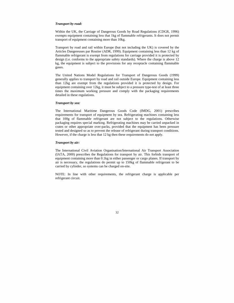
Transport by road:
Within the UK, the Carriage of Dangerous Goods by Road Regulations (CDGR, 1996)exempts equipment containing less that 1kg of flammable refrigerants. It does not permittransport of equipment containing more than 10kg.
Transport by road and rail within Europe (but not including the UK) is covered by theArticles Dangereuses par Routier (ADR, 1999). Equipment containing less than 12 kg offlammable refrigerant is exempt from regulations for carriage provided it is protected bydesign (i.e. conforms to the appropriate safety standards). Where the charge is above 12kg, the equipment is subject to the provisions for any receptacle containing flammablegases.
The United Nations Model Regulations for Transport of Dangerous Goods (1999)generally applies to transport by road and rail outside Europe. Equipment containing lessthan 12kg are exempt from the regulations provided it is protected by design. Forequipment containing over 12kg, it must be subject to a pressure type-test of at least threetimes the maximum working pressure and comply with the packaging requirementsdetailed in these regulations.
Transport by sea:
The International Maritime Dangerous Goods Code (IMDG, 2001) prescribesrequirements for transport of equipment by sea. Refrigerating machines containing lessthat 100g of flammable refrigerant are not subject to the regulations. Otherwisepackaging requires special marking. Refrigerating machines may be carried unpacked incrates or other appropriate over-packs, provided that the equipment has been pressuretested and designed so as to prevent the release of refrigerant during transport conditions.However, if the charge is less that 12 kg then these requirements do not apply.
Transport by air:
The International Civil Aviation Organisation/International Air Transport Association(IATA, 2000) prescribes the Regulations for transport by air. This forbids transport ofequipment containing more than 0.1kg in either passenger or cargo planes. If transport byair is necessary, the regulations do permit up to 150kg of flammable refrigerant to becarried by cylinder, so systems can be charged on-site.
NOTE: In line with other requirements, the refrigerant charge is applicable perrefrigerant circuit.

33
4. REFERENCES
These standards and codes of practice are current at the time of publishing. Checksshould be made to ensure these are still current.
1. BRA Guide to Good Commercial Refrigeration Practice, Issue 1 (ISBN 1870623 15 0) British Refrigeration Association (April 2000)
2. BRA Joining of Copper Pipework for refrigeration Systems, issue 2 (ISBN 1870623 14 2) – specification of procedures for manual flame brazing and brazerassessment. British Refrigeration Association (February 2000)
3. BRA Task Procedures and Risk Assessments: Model Method Statements, issue 3(ISBN 1 870623 13 4) British Refrigeration Association (April 2000)
4. BS 4434: 1995 Specification for safety and environmental aspects in the design,construction and installation of refrigerating appliances and systems., BSI, London1997.
5. BS 5345: 1976 Code of practice for the selection, installation and maintenance ofelectrical apparatus for use in potentially explosive atmospheres (other than miningapplications or explosive processing and manufacture)
6. BS EN 1127-1: 1998 Explosive atmospheres – explosion prevention and protection.Basic concepts and methodology.
7. BS EN 378: 2000 Refrigerating systems and heat pumps – safety and environmentalrequirements.
8. BS EN 60079-10: 1998. Electrical Apparatus for Explosive Gas Atmospheres.Classification of hazardous areas.
9. BS EN 60079-11: 1997 Electrical Apparatus for Explosive Gas Atmospheres.Electrical apparatus with type of protection “i”.
10. BS EN 60079-14: 1997 Electrical Apparatus for Explosive Gas Atmospheres.Electrical installations in hazardous areas (other than mines).
11. BS EN 60079-15: 1994 Electrical Apparatus for Explosive Gas Atmospheres.Electrical apparatus with type of protection “n”.
12. BS EN 60079-18: 1994 Electrical Apparatus for Explosive Gas Atmospheres.Electrical apparatus with type of protection “m”.
13. BS EN 60335-2-24: 1994 Specification of household and similar electricalappliances. Particular requirements. Refrigerators, food-freezers and ice-makers.

34
14. BS EN 60335-2-34: 2000 Specification of household and similar electricalappliances. Particular requirements. Motor-compressors.
15. BS EN 60335-2-40: 1993 Specification of household and similar electricalappliances. Particular requirements. Electric heat pumps, air conditioners anddehumidifiers.
16. Colbourne, D., Butler, D. J. G., Dispersion of flammable refrigerants from splitair-conditioners, Proc. IIIR 4th Gustav Lorentzen Conf. on Natural Working Fluids,Purdue, USA, 2000.
17. pr EN 12693 Refrigerating systems and heat pumps – safety and environmentalrequirements – positive displacement refrigerant compressors (Draft at time ofpublication, 1998)
18. prEN12284 Pressure Relief Valves
19. pr EN 13313. Refrigerating Systems and Heat Pumps - Competence of Personnel(Draft at time of publication, 1999)
20. EN 50054 Electrical apparatus for the detection and measurement of combustiblegases – General requirements and test methods.
21. EN 50057 Electrical apparatus for the detection and measurement of combustiblegases – Performance requirements for Group II apparatus indicating up to 100%lower explosive limit.
22. EN 60529: 1991 Degrees of protection provided by enclosure (IP code)
23. IATA, 2000, International Air Transport Association, Dangerous GoodsRegulations, 40th Edition, Geneva.
24. IEC 60079-0: 1998 Electrical Apparatus for Explosive Gas Atmospheres. Generalrequirements.
25. IEC 60335-2-89 (Draft at time of publication). Specification of household andsimilar electrical appliances. Particular requirements. Commercial refrigeratingappliances with an incorporated or remote refrigerant condensing unit.
26. IMDG, 2001, International Maritime Organisation, International MaritimeDangerous Goods Code, London.
27. United Nations, 1999, Transport of Dangerous Goods Model Regulations, 10th
Edition, The Stationary Office, London.
28. United Nations, 1999, European Agreement concerning the International carriageof dangerous good by road (ADR) and protocol of Signature, EconomicCommission for Europe, The Stationary Office, London.
36
The information or advice contained in this document is intended for use only by persons who have adequatetechnical training in the fields appropriate to the contents of the document. This document has been compiled asan aid only and the information or advice should be verified before it is put to any use by any person. The usershould also establish the applicability of the information or advice in relation to any specific circumstance. Whilethe information and advice is believed to be correct, the Air Conditioning and Refrigeration Industry Board, itsofficers, employees and agents disclaim responsibility for any inaccuracies contained within the documentincluding those due to any negligence in the preparation and publication of the said document.
© 2001 Air Conditioning and Refrigeration Industry BoardFirst Published February 2001
ISBN 1 872719 13 9
Further copies of this guide are available fromThe Air Conditioning and Refrigeration Industry Board at:
Kelvin House, 76 Mill Lane, Carshalton, Surrey SM5 2JRTel 0208 647 7033 Fax 0208 773 0165 [email protected] www.acrib.org.uk