Hydraulic Workovers
34
Hydraulic Workovers, HWO • A hydraulic workover is an intervention accomplished under well pressure and without killing the well. Some snubbing operations, most wireline work and most coiled tubing work is done under pressure, through isolation barriers. The difference with HWO is that the conveyance system allows circulation at higher rates than CT, rotation and heavier pulls than wireline or CT. • The ability to move pipe under pressure eliminates well kills, damage, cleanup time and loss of production. • Snubbing is a larger well work segment that may include rig draw-works assistance (mechanical) pipe movement and hydraulic units as well. – Snubbing – moving pipe against pressure that would push it from the well. – Stripping – moving pipe when its weight would pull it into the well if released. 8/25/2015 1 George E. King Engineering GEKEngineering.com
-
Upload
kevin-steinbach -
Category
Documents
-
view
45 -
download
5
description
N/A
Transcript of Hydraulic Workovers
Hydraulic Workovers, HWO
• A hydraulic workover is an intervention accomplished under well pressure and without killing the well. Some snubbing operations, most wireline work and most coiled tubing work is done under pressure, through isolation barriers. The difference with HWO is that the conveyance system allows circulation at higher rates than CT, rotation and heavier pulls than wireline or CT.
• The ability to move pipe under pressure eliminates well kills, damage, cleanup time and loss of production.
• Snubbing is a larger well work segment that may include rig draw-works assistance (mechanical) pipe movement and hydraulic units as well.
– Snubbing – moving pipe against pressure that would push it from the well.
– Stripping – moving pipe when its weight would pull it into the well if released.
8/25/2015 1 George E. King Engineering
GEKEngineering.com

Other HWO Operations
• Hot Tapping – drilling through pipe with isolation and barriers to provide a circulation port to an area with trapped pressure.
• Gate Valve Drilling – provides an opening through a stuck gate valve
• Related Operations
– Freezing the wellhead
– Sealant injection
8/25/2015 2 George E. King Engineering
GEKEngineering.com

Rig Assistance
• Rig draw-works assistance
– Rig or hydraulic jacks
– Slower than hydraulic
– Used for larger pipe – typically casing when running in against a kick or a flow drilled well.
Draw works
Traveling Slips
Floor Sheaves
Tube being moved
BOP and stripper seal
Bottom plug
8/25/2015 3 George E. King Engineering
GEKEngineering.com

Hydraulic Workover Equipment
• Provide pressure and load control of tubulars run in and removed from the well.
• Usually have three or more barriers with contingencies for repair while the job is in progress.
• The bottom of the pipe is plugged while running.
8/25/2015 4
George E. King Engineering GEKEngineering.com
HWO Job Procedure/Equipment Illustrations
1. Operate within load, pressure and component ratings.
2. Modifications to critical components require engineering authorization and redesign.
3. Pipe guides (or braces) are required when snubbing.
4. BOP stack must meet minimum specific requirements for pressures, repair options and spacing required by couplings and tools.
5. Slips must include both traveling and stationary slips to hold both pipe light and pipe heavy operations. Multiple slips are required for specific operations – pulling stuck pipe, milling, pulling shallow plugs, etc.
6. Daylight may limit operations. 8/25/2015 5
George E. King Engineering GEKEngineering.com

HWO Job Procedure/Equipment Illustrations
7. Max pull set by safety factor and pipe condition – usually 80% of minimum yield.
8. Max wellhead working pressure is 80% of rated pressure at equipment condition.
9. Modifications to critical components require engineering authorization and redesign.
10. Use hydraulic lock when milling. Do not use clamps when moving pipe or transmitting torque.
11. Pressure test BOP stack and all lines and valves before entering well.
12. Have an open stabbing valve with wrench in the basket.
13. Pumping units must have a relief valve (manned while operating).
14. Kill lines must have a check valve close to the BOP stack.
Part of a list from Halliburton 8/25/2015 6
George E. King Engineering GEKEngineering.com
Hydraulic Workover Unit
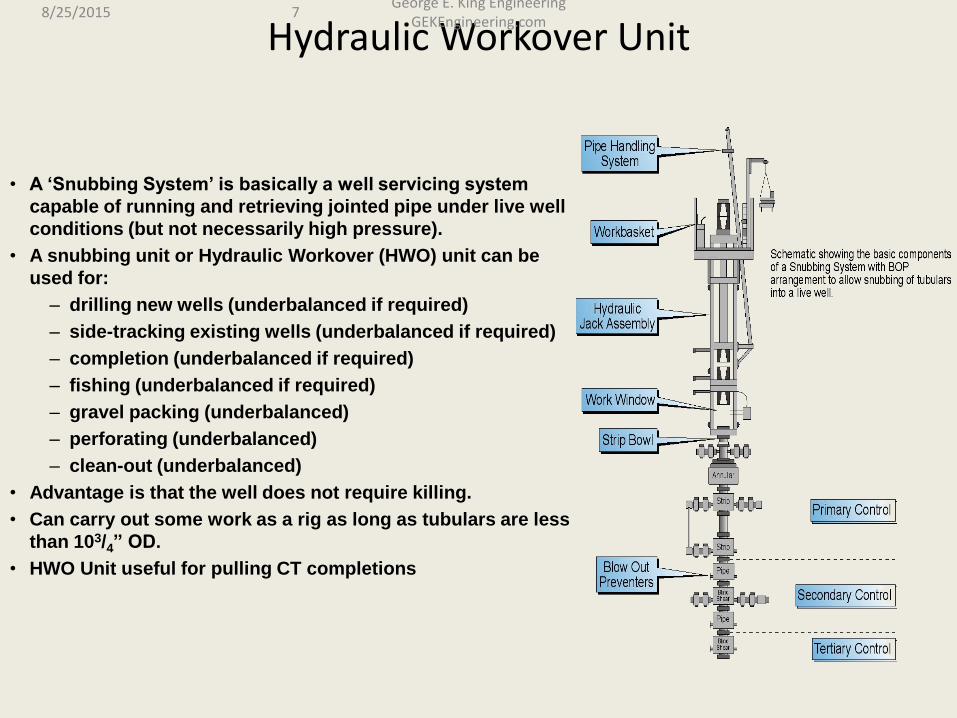
• A ‘Snubbing System’ is basically a well servicing system
capable of running and retrieving jointed pipe under live well
conditions (but not necessarily high pressure).
• A snubbing unit or Hydraulic Workover (HWO) unit can be
used for:
– drilling new wells (underbalanced if required)
– side-tracking existing wells (underbalanced if required)
– completion (underbalanced if required)
– fishing (underbalanced if required)
– gravel packing (underbalanced)
– perforating (underbalanced)
– clean-out (underbalanced)
• Advantage is that the well does not require killing.
• Can carry out some work as a rig as long as tubulars are less
than 103/4” OD.
• HWO Unit useful for pulling CT completions
8/25/2015 7 George E. King Engineering
GEKEngineering.com
Live Well Workovers
• less fluids lost to formation = less damage
• shorter time with well off-line
• less problems with kill fluids
8/25/2015 8 George E. King Engineering
GEKEngineering.com

Components
• A pipe movement system - cable assisted or rig assisted
• A sealing stack of pipe rams that allows passage of tool joints and equipment into and out of a well under pressure.
8/25/2015 9 George E. King Engineering
GEKEngineering.com

Normal tubulars used for HWO
8/25/2015 10 George E. King Engineering
GEKEngineering.com
A view of the pressure connection tube
between the upper isolation chamber
and the well.
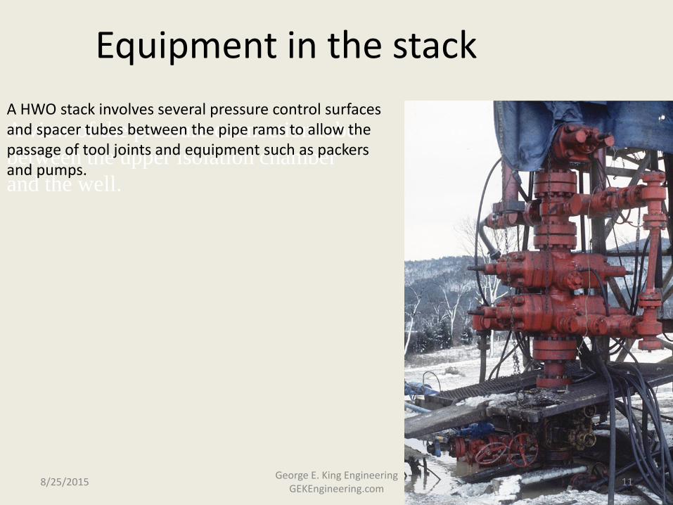
Equipment in the stack
A HWO stack involves several pressure control surfaces and spacer tubes between the pipe rams to allow the passage of tool joints and equipment such as packers and pumps.
8/25/2015 11 George E. King Engineering
GEKEngineering.com
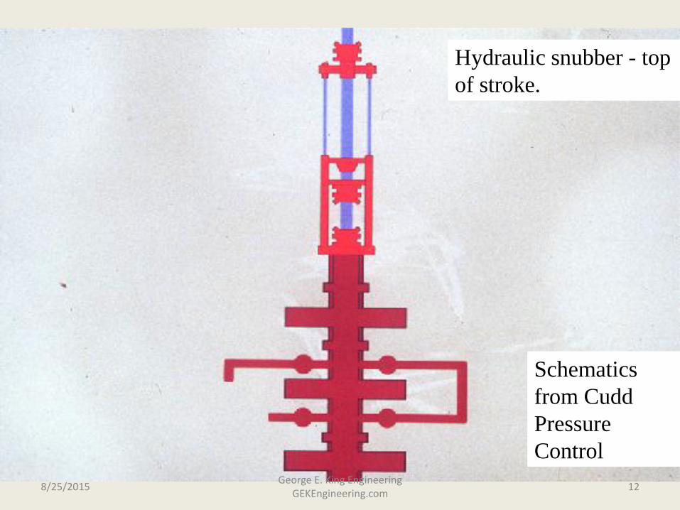
Schematics
from Cudd
Pressure
Control
Hydraulic snubber - top
of stroke.
8/25/2015 12 George E. King Engineering
GEKEngineering.com

Pipe slip
elements in
hydraulic
snubber
8/25/2015 13 George E. King Engineering
GEKEngineering.com
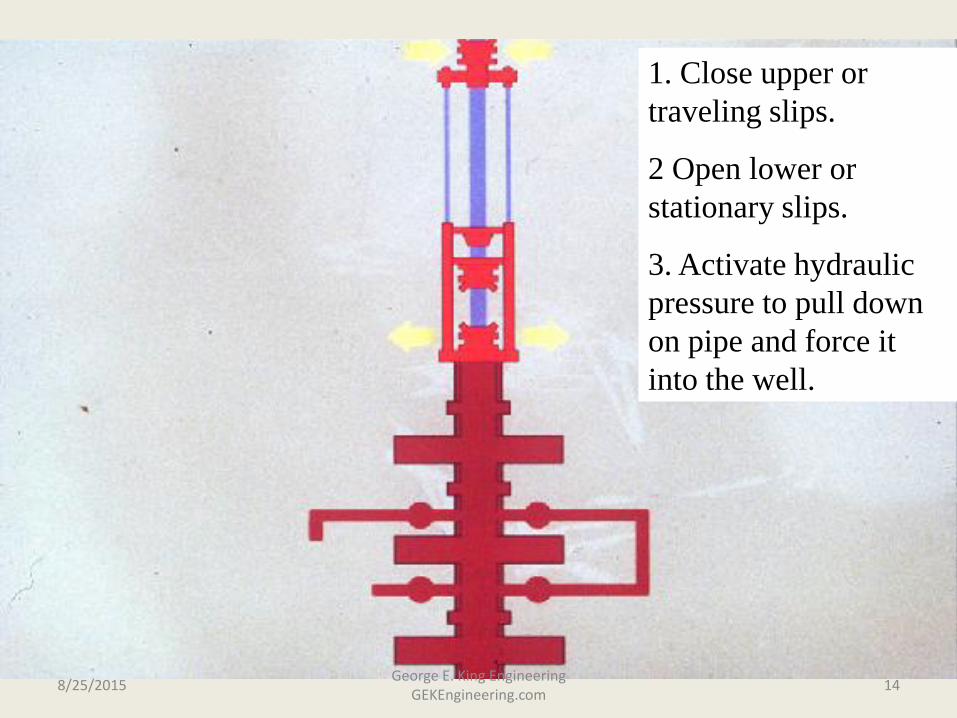
1. Close upper or
traveling slips.
2 Open lower or
stationary slips.
3. Activate hydraulic
pressure to pull down
on pipe and force it
into the well.
8/25/2015 14 George E. King Engineering
GEKEngineering.com
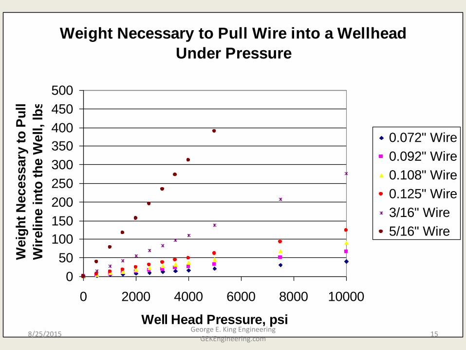
Weight Necessary to Pull Wire into a Wellhead
Under Pressure
0
50
100
150
200
250
300
350
400
450
500
0 2000 4000 6000 8000 10000
Well Head Pressure, psi
Weig
ht
Necessary
to
Pu
ll
Wir
elin
e in
to t
he W
ell, lb
s
0.072" Wire
0.092" Wire
0.108" Wire
0.125" Wire
3/16" Wire
5/16" Wire
8/25/2015 15 George E. King Engineering
GEKEngineering.com

Snubbing Pressure vs. WHP and Wire or
Tubing Size
0
5000
10000
15000
20000
25000
30000
35000
40000
45000
50000
0 1000 2000 3000 4000 5000
Well Head Pressure, psi
Sn
ub
bin
g F
orc
e o
r W
eig
ht
Re
qu
ire
d t
o E
nte
r W
ellh
ea
d,
lbs
0.108" Wire
3/16" Wire
1.5" CT
2-3/8" Tbg
2-7/8" Tbg
3-1/2" Tbg
4-1/2" Tbg
8/25/2015 16 George E. King Engineering
GEKEngineering.com
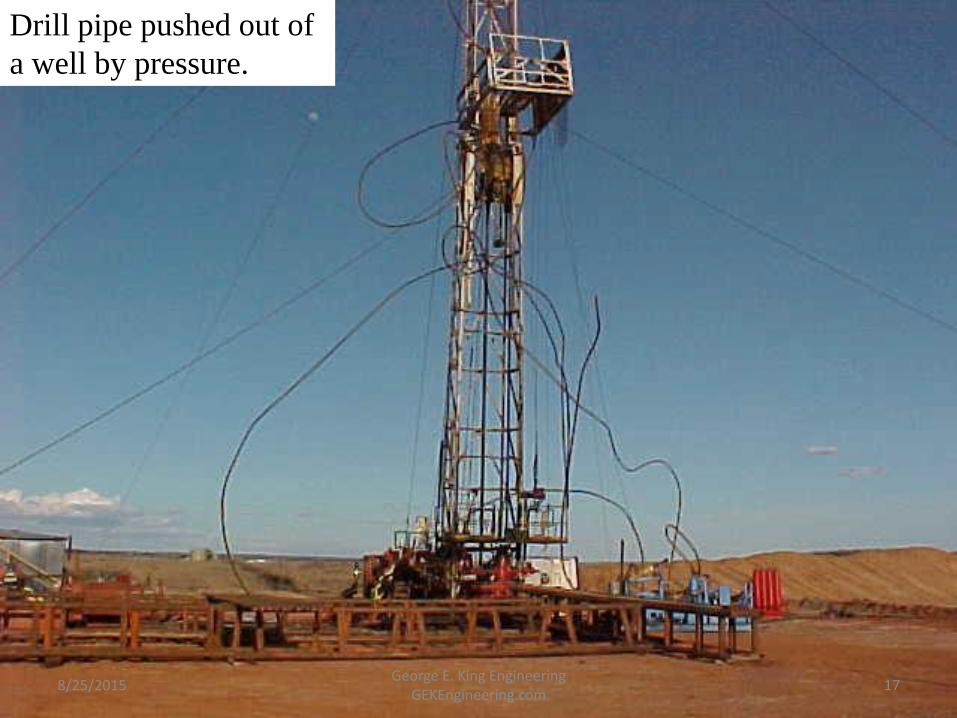
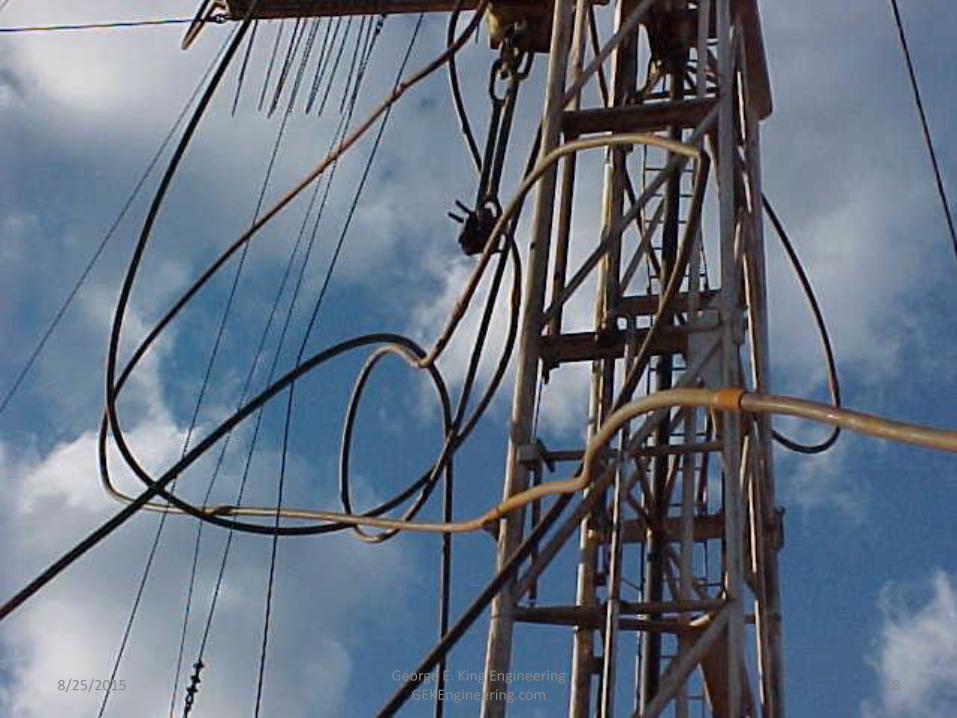
Drill pipe pushed out of
a well by pressure.
8/25/2015 17 George E. King Engineering
GEKEngineering.com
8/25/2015 18 George E. King Engineering
GEKEngineering.com

Hydraulic snubber
nearing bottom of
stroke.
8/25/2015 19 George E. King Engineering
GEKEngineering.com

Tool joint nearing
slips.
8/25/2015 20 George E. King Engineering
GEKEngineering.com
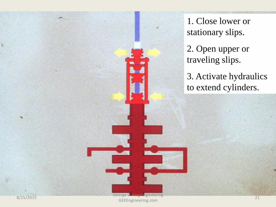
1. Close lower or
stationary slips.
2. Open upper or
traveling slips.
3. Activate hydraulics
to extend cylinders.
8/25/2015 21 George E. King Engineering
GEKEngineering.com

Stop tool joint
immediately above top
pipe ram on snubbing
stack.
8/25/2015 22 George E. King Engineering
GEKEngineering.com

Pipe seal
elements
8/25/2015 23 George E. King Engineering
GEKEngineering.com
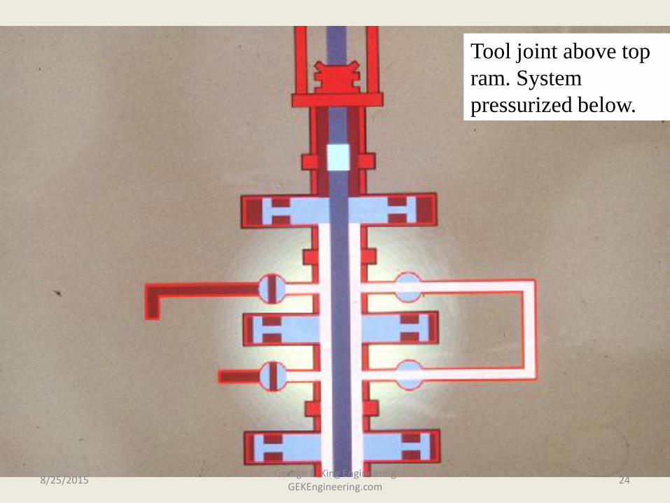
Tool joint above top
ram. System
pressurized below.
8/25/2015 24 George E. King Engineering
GEKEngineering.com

Middle pipe seal closed
8/25/2015 25 George E. King Engineering
GEKEngineering.com
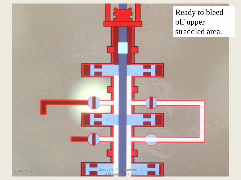
Ready to bleed
off upper
straddled area.
8/25/2015 26 George E. King Engineering
GEKEngineering.com
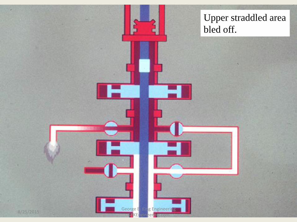
Upper straddled area
bled off.
8/25/2015 27 George E. King Engineering
GEKEngineering.com

Open upper ram and
pass tool joint into
upper straddled area.
8/25/2015 28 George E. King Engineering
GEKEngineering.com

Close upper ram and
prepare to pressurize
upper straddled area.
8/25/2015 29 George E. King Engineering
GEKEngineering.com
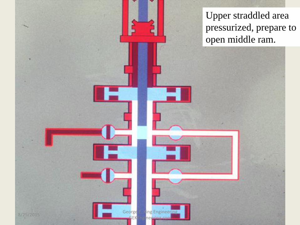
Upper straddled area
pressurized, prepare to
open middle ram.
8/25/2015 30 George E. King Engineering
GEKEngineering.com

Open middle ram
and pass tool joint
into well.
8/25/2015 31 George E. King Engineering
GEKEngineering.com
Sealing against the pipe
• Stripper Friction has several variables – pipe OD, pipe surface condition, lubrication, type of packing, length of packing, etc. In general, for a good seal:
– 500 lb per square inch on a stripper packing
– 1000 lb per square inch on an annular
8/25/2015 32 George E. King Engineering
GEKEngineering.com
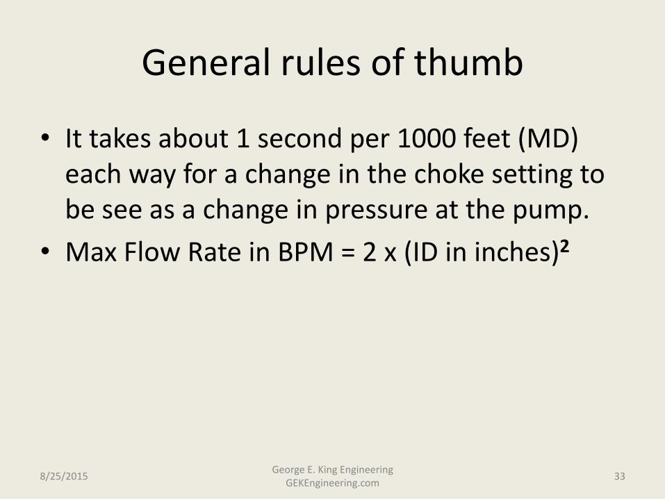
General rules of thumb
• It takes about 1 second per 1000 feet (MD) each way for a change in the choke setting to be see as a change in pressure at the pump.
• Max Flow Rate in BPM = 2 x (ID in inches)2
8/25/2015 33 George E. King Engineering
GEKEngineering.com
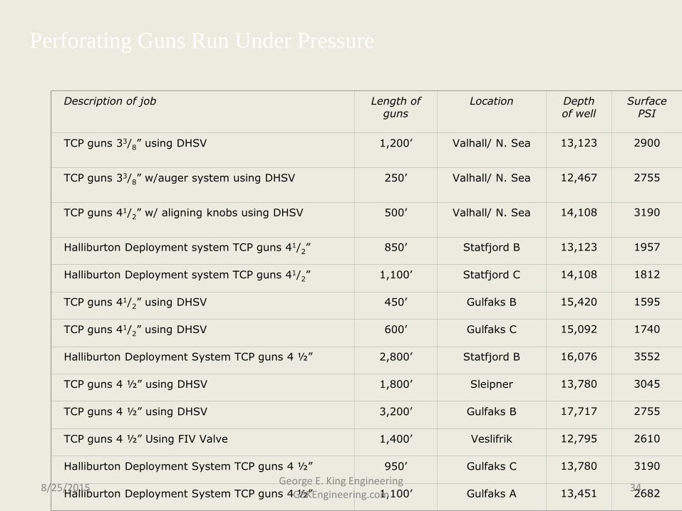
Description of job
Length of
guns
Location
Depth of well
Surface PSI
TCP guns 33/8” using DHSV
1,200’
Valhall/ N. Sea
13,123
2900
TCP guns 33/8” w/auger system using DHSV
250’
Valhall/ N. Sea
12,467
2755
TCP guns 41/2” w/ aligning knobs using DHSV
500’
Valhall/ N. Sea
14,108
3190
Halliburton Deployment system TCP guns 41/2”
850’
Statfjord B
13,123
1957
Halliburton Deployment system TCP guns 41/2”
1,100’
Statfjord C
14,108
1812
TCP guns 41/2” using DHSV
450’
Gulfaks B
15,420
1595
TCP guns 41/2” using DHSV
600’
Gulfaks C
15,092
1740
Halliburton Deployment System TCP guns 4 ½”
2,800’
Statfjord B
16,076
3552
TCP guns 4 ½” using DHSV
1,800’
Sleipner
13,780
3045
TCP guns 4 ½” using DHSV
3,200’
Gulfaks B
17,717
2755
TCP guns 4 ½” Using FIV Valve
1,400’
Veslifrik
12,795
2610
Halliburton Deployment System TCP guns 4 ½”
950’
Gulfaks C
13,780
3190
Halliburton Deployment System TCP guns 4 ½”
1,100’
Gulfaks A
13,451
2682
Perforating Guns Run Under Pressure
8/25/2015 34 George E. King Engineering
GEKEngineering.com