Hydraulic Ram; by Allen Inversin, VITA
111
Home -immediately access 800+ free online publications. Download CD3WD (680 Megabytes) and distribute it to the 3rd World. CD3WD is a 3rd World Development private-sector initiative, mastered by Software Developer Alex Weir and hosted by GNUveau_Networks (From globally distributed organizations, to supercomputers, to a small home server, if it's Linux, we know it.) home .cd3wd . ar .cn .de . en . es .fr .id . it . ph . po . ru .sw HYDRAULIC RAM by: Allen Inversin Illustrated by: George R. Clark Published by: VITA 1600 Wilson Boulevard, Suite 500 Arlington, Virginia 22209 USA Tel: 703/276-1800 * Fax: 703/243-1865 Internet: [email protected] ISBN 0-86619-243-3 [C] 1985, Volunters in Technical Assistance, Inc. 1987, Second Printing HYDRAULIC RAM 18/10/2011 <b> HYDRAULIC RAM file:///H:/vita/HYDRARAM/EN/HYDRARAM.HTM 1/111
description
Hydraulic Ram; by Allen Inversin, VITA
Transcript of Hydraulic Ram; by Allen Inversin, VITA

Home-immediately access 800+ free online publications. Download CD3WD (680 Megabytes) and distribute it to
the 3rd World. CD3WD is a 3rd World Development private-sector initiative, mastered by Software Developer Alex
Weir and hosted by GNUveau_Networks (From globally distributed organizations, to supercomputers, to a small
home server, if it's Linux, we know it.)
home.cd3wd.ar.cn.de.en.es.fr.id.it.ph.po.ru.sw
HYDRAULIC RAM
by:
Allen Inversin
Illustrated by:
George R. Clark
Published by:
VITA
1600 Wilson Boulevard, Suite 500
Arlington, Virginia 22209 USA
Tel: 703/276-1800 * Fax: 703/243-1865
Internet: [email protected]
ISBN 0-86619-243-3
[C] 1985, Volunters in Technical Assistance, Inc.
1987, Second Printing
HYDRAULIC RAM
18/10/2011 <b> HYDRAULIC RAM
file:///H:/vita/HYDRARAM/EN/HYDRARAM.HTM 1/111

I. INTRODUCTION
What it is and How it is Used
Background on the Papua New Guinea Ram
Decision Factors
Making the Decision and Following Through
II. PRE-CONSTRUCTION CONSIDERATIONS
Site Selection
Tools Materials
III. CONSTRUCTION
Waste Valve Construction
Check Valve Construction
IV. INSTALLATION, OPERATION, and MAINTENANCE
V. FURTHER INFORMATION RESOURCES
APPENDIX I. ADDITIONAL PERFORMANCE CONSIDERATIONS
APPENDIX II. CONVERSION TABLES
APPENDIX III. DECISION-MAKING WORK SHEET
APPENDIX IV. RECORD-KEEPING WORK SHEET
18/10/2011 <b> HYDRAULIC RAM
file:///H:/vita/HYDRARAM/EN/HYDRARAM.HTM 2/111

I. INTRODUCTION
WHAT IT IS AND HOW IT IS USED
A hydraulic ram is a pump that uses the power of falling water
to force a small portion of the water to a height greater than
the source. Water can be forced about as far horizontally as
desired, but greater distances require larger pipe, due to friction.
No external power is necessary.
With only two working parts, little maintenance is needed.
Leaves and trash must be cleaned away from the strainer on the
intake and the clack (automatic valve) and nonreturn or delivery
valve rubbers must be replaced if they get worn. The
original cost is almost the only cost.
Two things are needed to make the ram work: (1) enough water to
run the ram, and (2) enough height for water to fall through
the drive pipe to work the ram. A small amount of water with
plenty of fall will pump as much as a greater
amount of water with only a little
fall. The greater the height to
which the water must be raised,
the less water will be pumped.
<FIGURE 1>
06p01.gif (486x486)
18/10/2011 <b> HYDRAULIC RAM
file:///H:/vita/HYDRARAM/EN/HYDRARAM.HTM 3/111
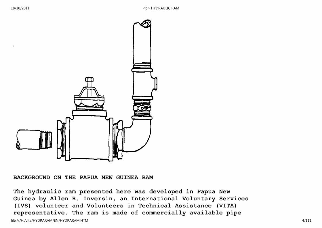
BACKGROUND ON THE PAPUA NEW GUINEA RAM
The hydraulic ram presented here was developed in Papua New
Guinea by Allen R. Inversin, an International Voluntary Services
(IVS) volunteer and Volunteers in Technical Assistance (VITA)
representative. The ram is made of commercially available pipe
18/10/2011 <b> HYDRAULIC RAM
file:///H:/vita/HYDRARAM/EN/HYDRARAM.HTM 4/111
fittings and two homemade valves that require only a drill press
and simple hand tools to construct. It has been tested at drive
heads of 5-4.0 and delivers up to a 70-head, or 20 times the
drive head. It will deliver several thousand liters per day.
The ram has been extensively tested and is being used successfully
in field conditions.
To introduce the ram in Papua New Guinea, working rams were set
up at demonstration sites near communities so that the community
members could see the ram at work. Meanwhile the construction
design for the ram was distributed by a local appropriate
technology group. And, in an important initiative, the ram was
manufactured locally as part of a small business effort.
DECISION FACTORS
The ram can fill a number of water-supply needs in situations
where water has to be lifted from a water source at a lower level
to a higher level. All that is required to make the ram work is
enough water falling fast enough to drive the water through the
pipe. And if the fall of water does not occur naturally (and
this is often the case), the fall can be created by running the
water down an inclined pipe so that momentum is created solely
within the pipe.
The features of this ram include the following:
o Water pumping.
18/10/2011 <b> HYDRAULIC RAM
file:///H:/vita/HYDRARAM/EN/HYDRARAM.HTM 5/111

o Water lifting.
o Capable of lifting/pumping water to higher levels.
o Non-polluting and energy-saving--it does not rely on
fossil fuel energy.
o Easy to maintain--it has only two moving parts.
o Inexpensive--the major cost is determined by the
amount of pipe needed.
o Easy to build, install, and operate.
o The intake must be kept unclogged--this could be a
problem if the water source is unusually turbid or
hard to keep free of debris, even when the intake is
screened.
o The amount of water capable of being delivered to the
higher level may be too small a quantity to meet the
need and/or to justify expenses.
o Use of a storage tank for water collection is a
necessity.
o Technical/mechanical difficulties arise with flows
under 2 gallons/minute and heads(*) of less than 1.5
18/10/2011 <b> HYDRAULIC RAM
file:///H:/vita/HYDRARAM/EN/HYDRARAM.HTM 6/111

meters.
o A drill press is needed for construction of several
parts.
MAKING THE DECISION AND FOLLOWING THROUGH
When determining whether a project is worth the time, effort,
and expense involved, consider social, cultural, and environmental
factors as well as economic ones. What is the purpose of
the effort? Who will benefit most? What will the consequences
be if the effort is successful? And if it fails?
Having made an informed technology choice, it's important to
keep good records. It is helpful from the beginning to keep
data on needs, site selection, resource availability, construction
progress, labor and materials costs, test findings, etc.
The information may prove an important reference if existing
plans and methods need to be altered. It can be helpful in pin-pointing
"what went wrong?" And, of course, it's important to
share data with other people. The technologies presented in
this and the other manuals in this series have been tested
carefully, and are actually used in many parts of the world.
However, extensive and controlled field tests have not been
conducted for many of them, even some of the most common ones.
Even though we know that these technologies work well in some
situations, it's important to gather specific information on why
they perform properly in one place and not in another.
18/10/2011 <b> HYDRAULIC RAM
file:///H:/vita/HYDRARAM/EN/HYDRARAM.HTM 7/111
(*) Head is the distance the water falls before hitting the ram.
Well-documented models of field activities provide important
information for the development worker. It is obviously important
for a development worker in Colombia to have the technical
design for a ram built and used in Senegal. But it is even
more important to have a full narrative about the ram that
provides details on materials, labor design changes, and so
forth. This model can provide a useful frame of reference.
A reliable bank of such field information is now growing. It
exists to help spread the word about these and other technologies,
lessening the dependence of the developing world on expensive
and finite energy resources.
A practical decision-making work sheet and record-keeping format
can be found in Appendix III and IV respectively.
II. PRE-CONSTRUCTION CONSIDERATIONS
The ram works as water runs down through the drive pipe, picking
up speed until it forces an automatic valve to close suddenly.
The weight of the moving water, suddenly stopped, creates a very
high pressure and forces some of the moving water past the
nonreturn or delivery valve into the air chamber, compressing
the air more and more until the energy of the moving water is
spent. This compressed air forces the water up the delivery
pipe to the storage tank in a steady stream.
It takes a lot of falling water to pump a little water up a
18/10/2011 <b> HYDRAULIC RAM
file:///H:/vita/HYDRARAM/EN/HYDRARAM.HTM 8/111
hill: only one/tenth or so of the water will reach the storage
tank at the top of the delivery pipe. So, while a working fall
from 50cm to 30 meters can be used to "power" a ram, a general
rule remains: "The more working fall available, the better."
Remember that fall can occur naturally or it can be achieved by
running the water down an inclined pipe so that it gathers
momentum.
The hydraulic ram described in this manual:
o Requires only commercially available pipe fittings and two
homemade valves.
o Can be constructed by following simple, step-by-step
instructions requiring no special skills.
o Requires the use of only hand tools and a drill press.
(The use of a lathe and grinder might simplify some aspects
of the work but are not necessary).
o Requires no welding, brazing, or soldering. Studs and nuts
and bolts are the primary load-carrying members. Epoxy
adhesive serves primarily as a sealant and is not subject
to large stresses.
o Should cost about $50 (US) (excluding the costs of drive
and delivery pipes, the ram foundation and housing, and
gate valves since these costs are part of any ram
installation, whether homemade or commercial).
18/10/2011 <b> HYDRAULIC RAM
file:///H:/vita/HYDRARAM/EN/HYDRARAM.HTM 9/111
o Shows efficiency comparable to that of commercial rams.
The amount of water required to operate the pump and the
amount of water delivered depend on a number of factors.
For delivery heads about ten times the drive head, the pump
can deliver about 2.5 liters/minute (3,600 liters/day).
Under usual operating conditions, the ram would use 30-40
liters/minute though it is possible to adjust the pump so
that less water is used. Under these conditions,
efficiencies of 65-75 percent are attainable.
SITE SELECTION
The most important pre-construction activity is determining the
suitability of a given water supply site for use with a hydraulic
ram.
Water may come from a spring on a hillside or from a river. The
water must be led into a position where it can pass through a
relatively short supply pipe to the ram, at a fairly steep angle
(about 300 [degrees] from the horizontal is good). A catch basin or
cistern can be used as the source for the drive pipe. In this
case, it is necessary to control the fall by length and angle of
the drive pipe. An open ditch such as one that supplies a water
wheel could be used. Be sure to put a strainer on top of the
drive pipe to keep trash out of the pipe and ram.
When water is to come from a natural flow, it is necessary to
measure flow and fall. Flow can be measured by making a temporary
18/10/2011 <b> HYDRAULIC RAM
file:///H:/vita/HYDRARAM/EN/HYDRARAM.HTM 10/111

dam and putting a large pipe or two through it. Then
catch and measure the water with a bucket of known volume for
approximately 15 minutes. This method will give a rough aproximation
on the drawing water available per minute.
<FIGURE 2>
06p06z.gif (600x600)
18/10/2011 <b> HYDRAULIC RAM
file:///H:/vita/HYDRARAM/EN/HYDRARAM.HTM 11/111

To measure the fall of water at the water site, you will need:
18/10/2011 <b> HYDRAULIC RAM
file:///H:/vita/HYDRARAM/EN/HYDRARAM.HTM 12/111
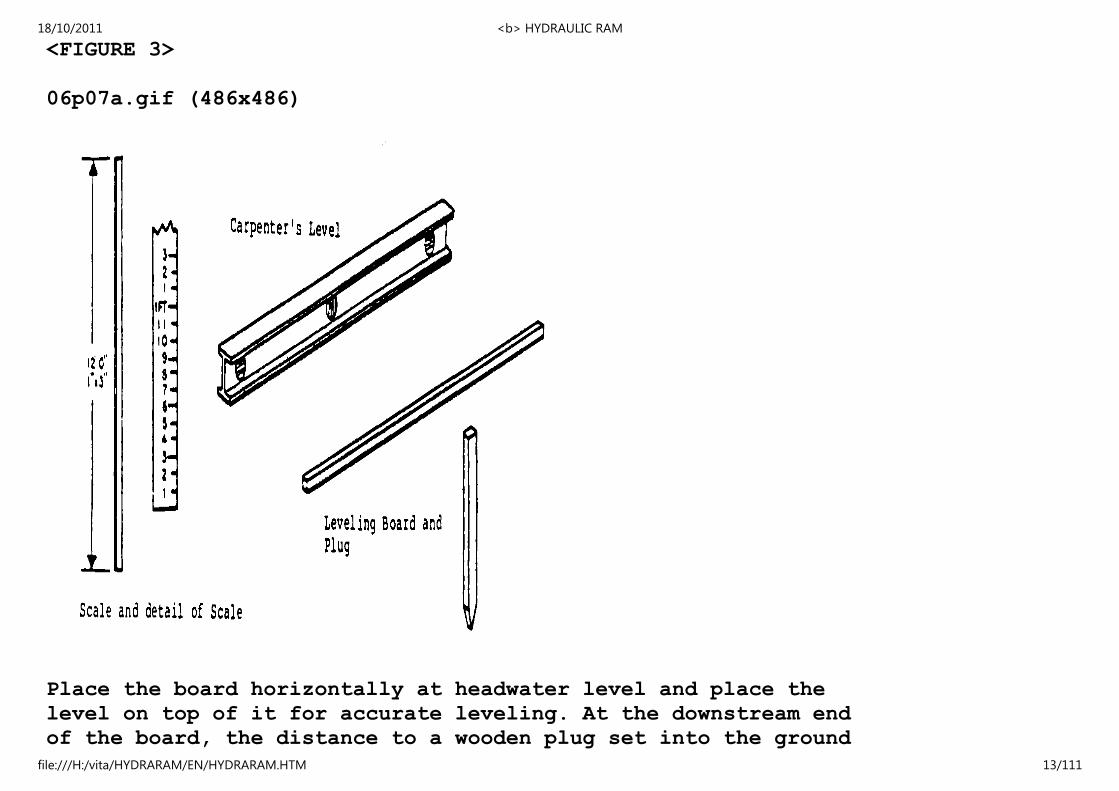
<FIGURE 3>
06p07a.gif (486x486)
Place the board horizontally at headwater level and place the
level on top of it for accurate leveling. At the downstream end
of the board, the distance to a wooden plug set into the ground
18/10/2011 <b> HYDRAULIC RAM
file:///H:/vita/HYDRARAM/EN/HYDRARAM.HTM 13/111

is measured with a scale.
<FIGURE 4>
06p07b.gif (600x600)
18/10/2011 <b> HYDRAULIC RAM
file:///H:/vita/HYDRARAM/EN/HYDRARAM.HTM 14/111
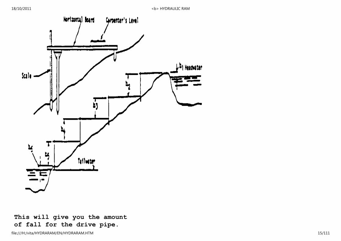
This will give you the amount
of fall for the drive pipe.
18/10/2011 <b> HYDRAULIC RAM
file:///H:/vita/HYDRARAM/EN/HYDRARAM.HTM 15/111

Use the same method for determining
the height to which
the water must be raised. This
height is measured from the
ram level. Once these figures
are known, it is possible to
determine how much water can
be raised to a given height.
Expressed as an equation,
Amount of water raised by ram =
(gallons) (feet)
Flow per minute (liters) X twice the fall (meters)
Three times the (meters) lift above ram
(feet)
It may be useful to use a particular problem:
A water supply site has a fall of three feet. The ram has to
lift the water 150 feet. The available flow is 100 gallons per
minute.
How much water will actually be delivered by a ram operating
under these conditions?
100 x 2(3)
water delivered = 3 x 150
18/10/2011 <b> HYDRAULIC RAM
file:///H:/vita/HYDRARAM/EN/HYDRARAM.HTM 16/111

water delivered = 600
450
1.3 gallons per minute
OR
water delivered = 78 gallons per hour
OR
1872 gallons per day
This is the information necessary for you to determine if the
ram can deliver enough water to meet your need. If there are
any questions at this point as to the amount of water actually
needed for a given purpose, e.g., village water supply, make
sure these questions are resolved before construction begins.
If more water is required than previously estimated, it may be
possible to increase the fall and/or the size of the drive and
delivery pipes. But it wil be far harder to make such changes
after ram construction and installation have begun.
The actual techniques used in construction of the ram will
depend on what tools are available. The method described here
is low-cost and simple, yet rugged and efficient. Those who
have had machine shop experience may choose other techniques of
construction.
<FIGURE 5>
06p09a.gif (600x600)
18/10/2011 <b> HYDRAULIC RAM
file:///H:/vita/HYDRARAM/EN/HYDRARAM.HTM 17/111

MATERIALS
18/10/2011 <b> HYDRAULIC RAM
file:///H:/vita/HYDRARAM/EN/HYDRARAM.HTM 18/111

The following list of galvanized pipe fittings is for the ram
only. Note: The ram was designed and built originally with pipe
fittings in standard American sizes. These sizes do not
translate directly into metric units. Where metric or other
standard pipe is available, equivalent sizes should be used.
All other measurements are metric.
3" x 1-1/2" reducer bushing (another size reducer bushing may be
required if a drive pipe smaller or larger than 1 1/2"
is used, see the comments on drive pipe diameter
on page 42).
2" x 1/2" reducer tee (if the delivery pipe is longer than
about a hundred meters, using a 2" x 3/4" or 2" x 1"
tee and the corresponding size delivery pipe would
reduce friction losses and permit more water to be
delivered).
2" pipe, about 50 cm long, 2" male-female elbow (90 degrees)
threaded at both ends
2" cap
3" x 2" reducer bushing
3" tee
WASTE AND CHECK VALVES
The only two parts of the pump that have to be built are the two
18/10/2011 <b> HYDRAULIC RAM
file:///H:/vita/HYDRARAM/EN/HYDRARAM.HTM 19/111
valves--the waste valve and the check valve. Sectional views of
these valves are shown below and on the next page. One method
for the construction of each valve is described; alternative
methods for their construction may be preferred.
<FIGURE 6>
06p10.gif (486x486)
18/10/2011 <b> HYDRAULIC RAM
file:///H:/vita/HYDRARAM/EN/HYDRARAM.HTM 20/111
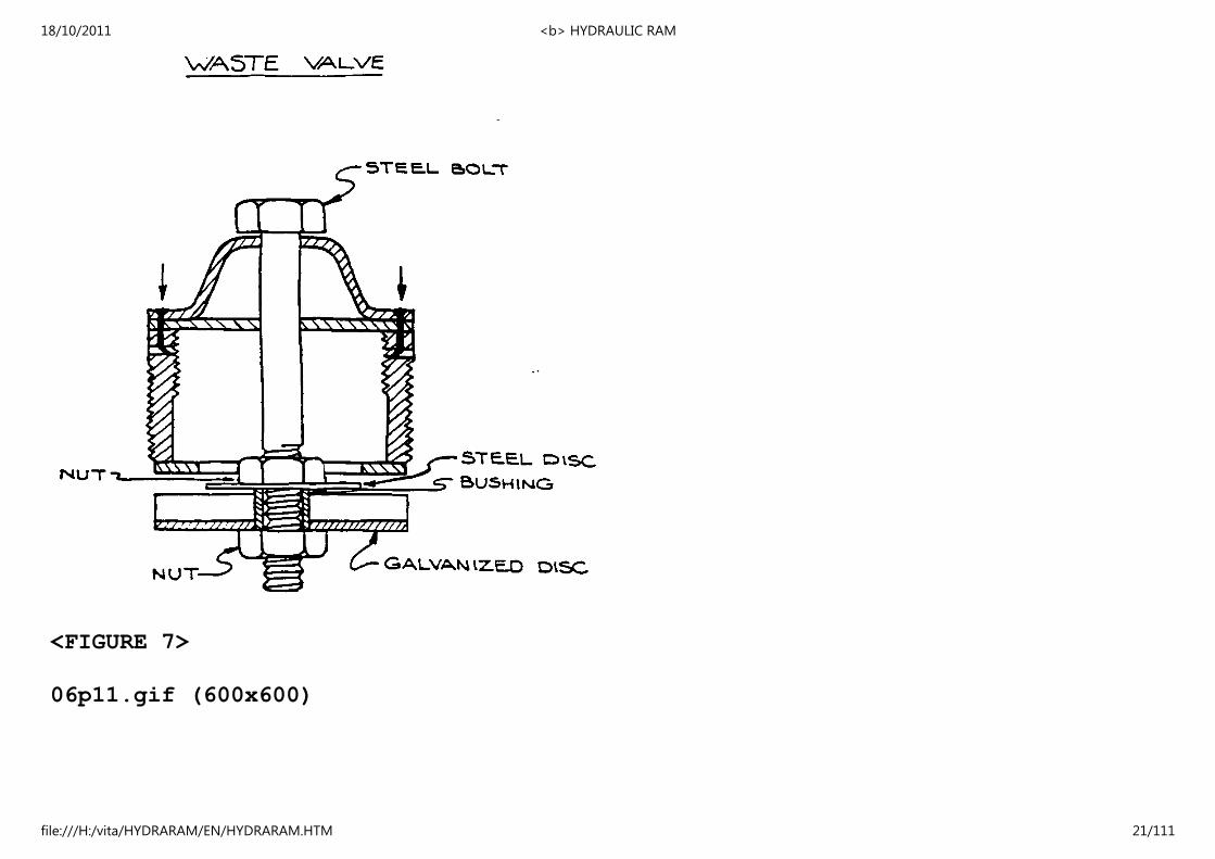
<FIGURE 7>
06p11.gif (600x600)
18/10/2011 <b> HYDRAULIC RAM
file:///H:/vita/HYDRARAM/EN/HYDRARAM.HTM 21/111
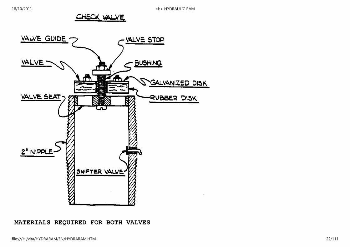
MATERIALS REQUIRED FOR BOTH VALVES
18/10/2011 <b> HYDRAULIC RAM
file:///H:/vita/HYDRARAM/EN/HYDRARAM.HTM 22/111
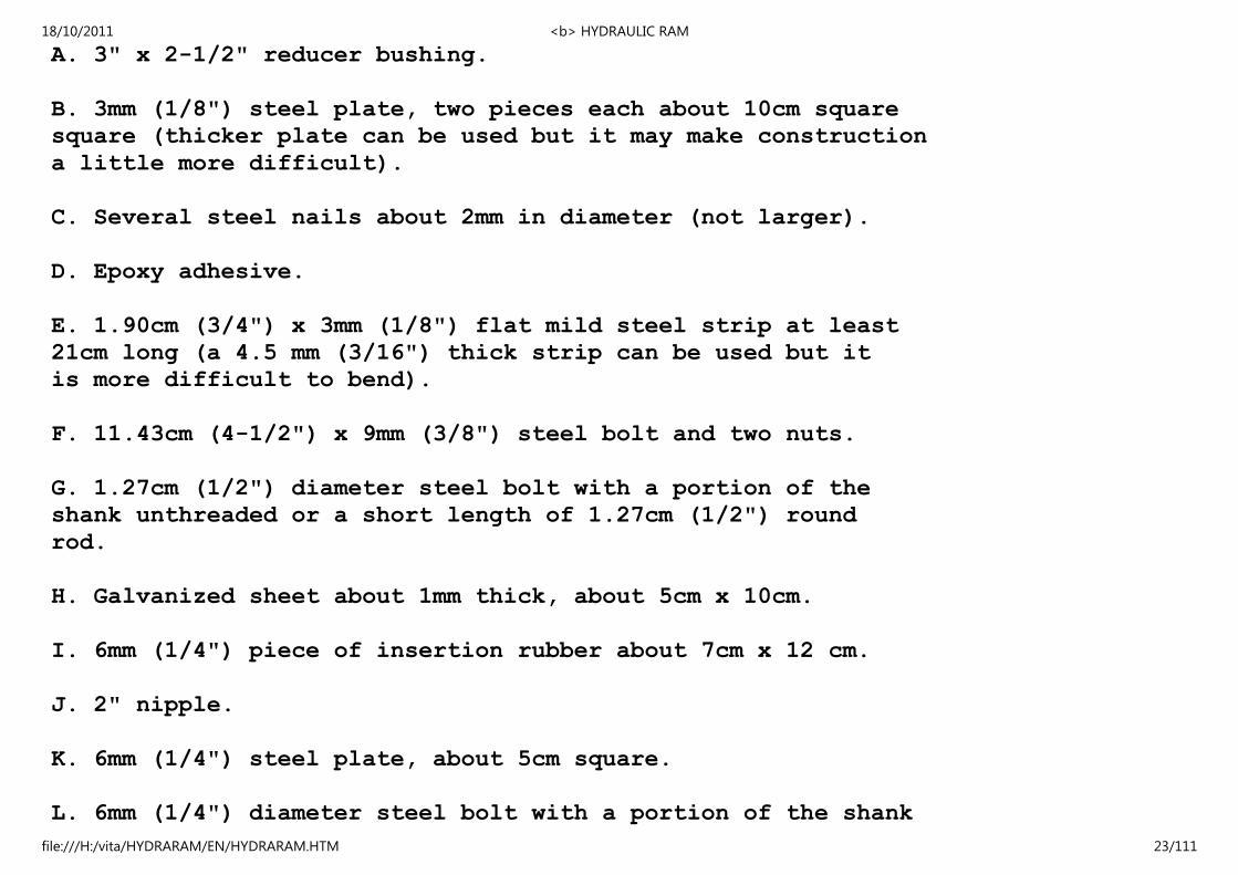
A. 3" x 2-1/2" reducer bushing.
B. 3mm (1/8") steel plate, two pieces each about 10cm square
square (thicker plate can be used but it may make construction
a little more difficult).
C. Several steel nails about 2mm in diameter (not larger).
D. Epoxy adhesive.
E. 1.90cm (3/4") x 3mm (1/8") flat mild steel strip at least
21cm long (a 4.5 mm (3/16") thick strip can be used but it
is more difficult to bend).
F. 11.43cm (4-1/2") x 9mm (3/8") steel bolt and two nuts.
G. 1.27cm (1/2") diameter steel bolt with a portion of the
shank unthreaded or a short length of 1.27cm (1/2") round
rod.
H. Galvanized sheet about 1mm thick, about 5cm x 10cm.
I. 6mm (1/4") piece of insertion rubber about 7cm x 12 cm.
J. 2" nipple.
K. 6mm (1/4") steel plate, about 5cm square.
L. 6mm (1/4") diameter steel bolt with a portion of the shank
18/10/2011 <b> HYDRAULIC RAM
file:///H:/vita/HYDRARAM/EN/HYDRARAM.HTM 23/111
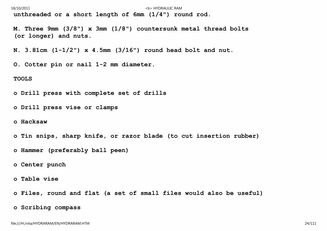
unthreaded or a short length of 6mm (1/4") round rod.
M. Three 9mm (3/8") x 3mm (1/8") countersunk metal thread bolts
(or longer) and nuts.
N. 3.81cm (1-1/2") x 4.5mm (3/16") round head bolt and nut.
O. Cotter pin or nail 1-2 mm diameter.
TOOLS
o Drill press with complete set of drills
o Drill press vise or clamps
o Hacksaw
o Tin snips, sharp knife, or razor blade (to cut insertion rubber)
o Hammer (preferably ball peen)
o Center punch
o Table vise
o Files, round and flat (a set of small files would also be useful)
o Scribing compass
18/10/2011 <b> HYDRAULIC RAM
file:///H:/vita/HYDRARAM/EN/HYDRARAM.HTM 24/111
o Pliers
o Emery or sandpaper
o Ruler
o Square
III. CONSTRUCTION
WASTE VALVE CONSTRUCTION
Make Valve Seat
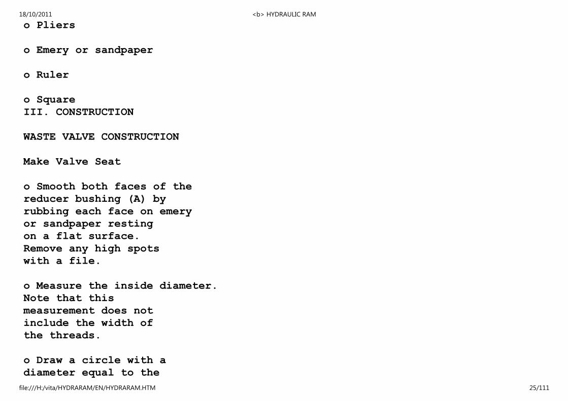
o Smooth both faces of the
reducer bushing (A) by
rubbing each face on emery
or sandpaper resting
on a flat surface.
Remove any high spots
with a file.
o Measure the inside diameter.
Note that this
measurement does not
include the width of
the threads.
o Draw a circle with a
diameter equal to the
18/10/2011 <b> HYDRAULIC RAM
file:///H:/vita/HYDRARAM/EN/HYDRARAM.HTM 25/111
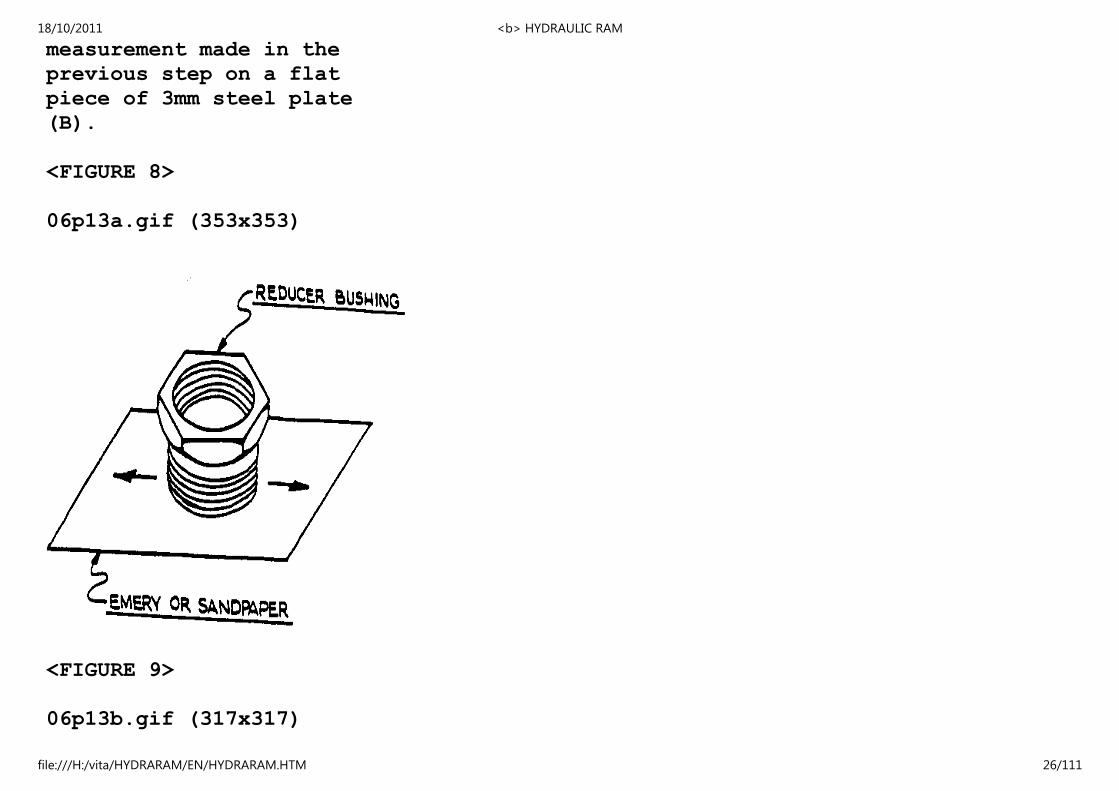
measurement made in the
previous step on a flat
piece of 3mm steel plate
(B).
<FIGURE 8>
06p13a.gif (353x353)
<FIGURE 9>
06p13b.gif (317x317)
18/10/2011 <b> HYDRAULIC RAM
file:///H:/vita/HYDRARAM/EN/HYDRARAM.HTM 26/111
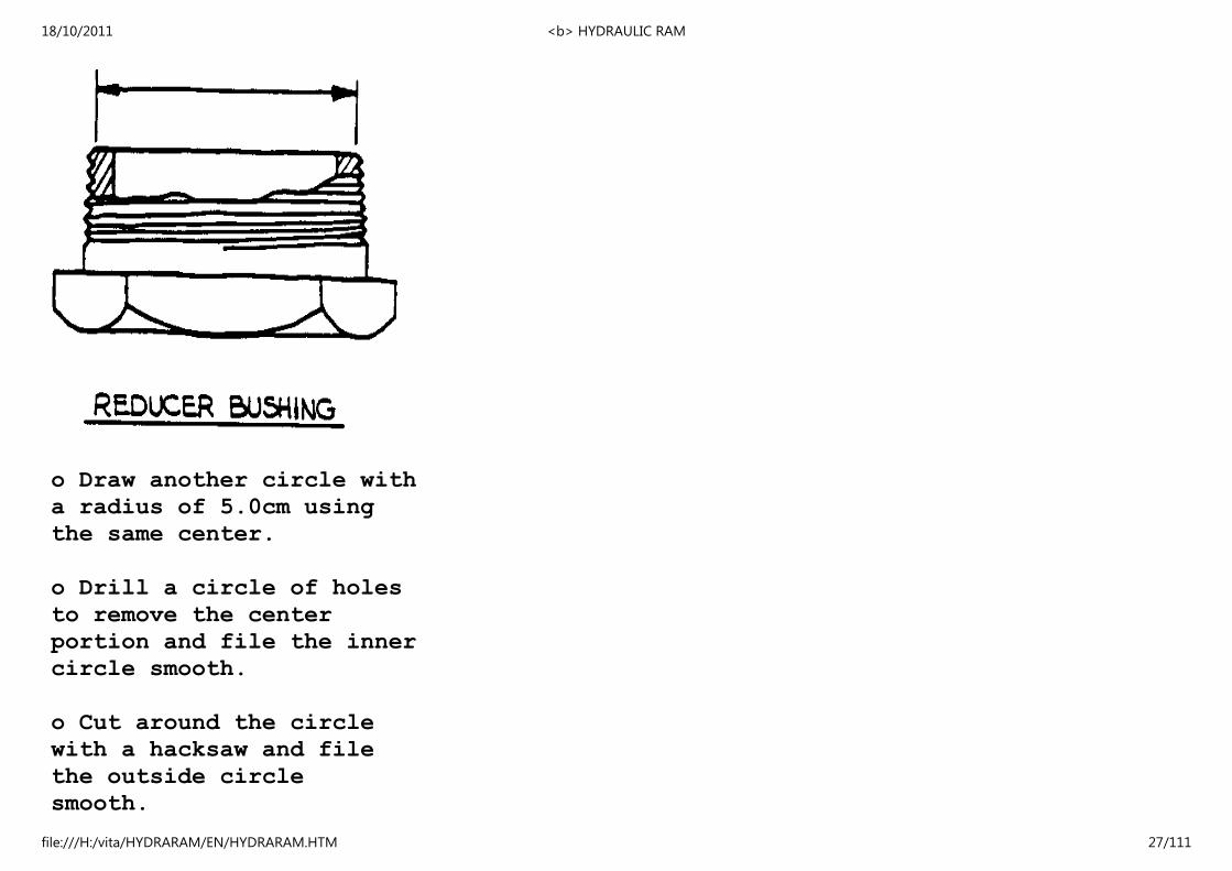
o Draw another circle with
a radius of 5.0cm using
the same center.
o Drill a circle of holes
to remove the center
portion and file the inner
circle smooth.
o Cut around the circle
with a hacksaw and file
the outside circle
smooth.
18/10/2011 <b> HYDRAULIC RAM
file:///H:/vita/HYDRARAM/EN/HYDRARAM.HTM 27/111
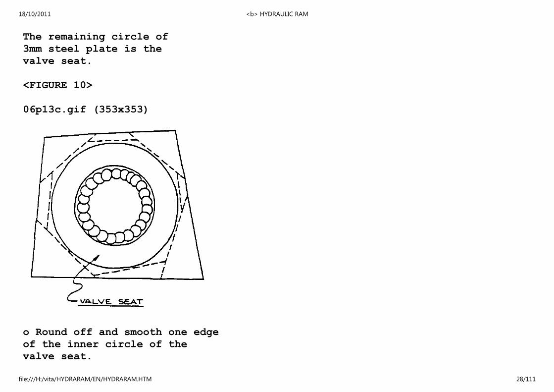
The remaining circle of
3mm steel plate is the
valve seat.
<FIGURE 10>
06p13c.gif (353x353)
o Round off and smooth one edge
of the inner circle of the
valve seat.
18/10/2011 <b> HYDRAULIC RAM
file:///H:/vita/HYDRARAM/EN/HYDRARAM.HTM 28/111

Fasten the Valve Seat to the Reducer Bushing
o Center--carefully--the valve seat on the bushing and
then drill three holes the size of the nails (C)
around the outside of the valve seat into the center
of the bushing wall as shown and countersink slightly.
<FIGURE 11>
06p14a.gif (317x317)
To ensure that the holes
in the valve seat and
18/10/2011 <b> HYDRAULIC RAM
file:///H:/vita/HYDRARAM/EN/HYDRARAM.HTM 29/111
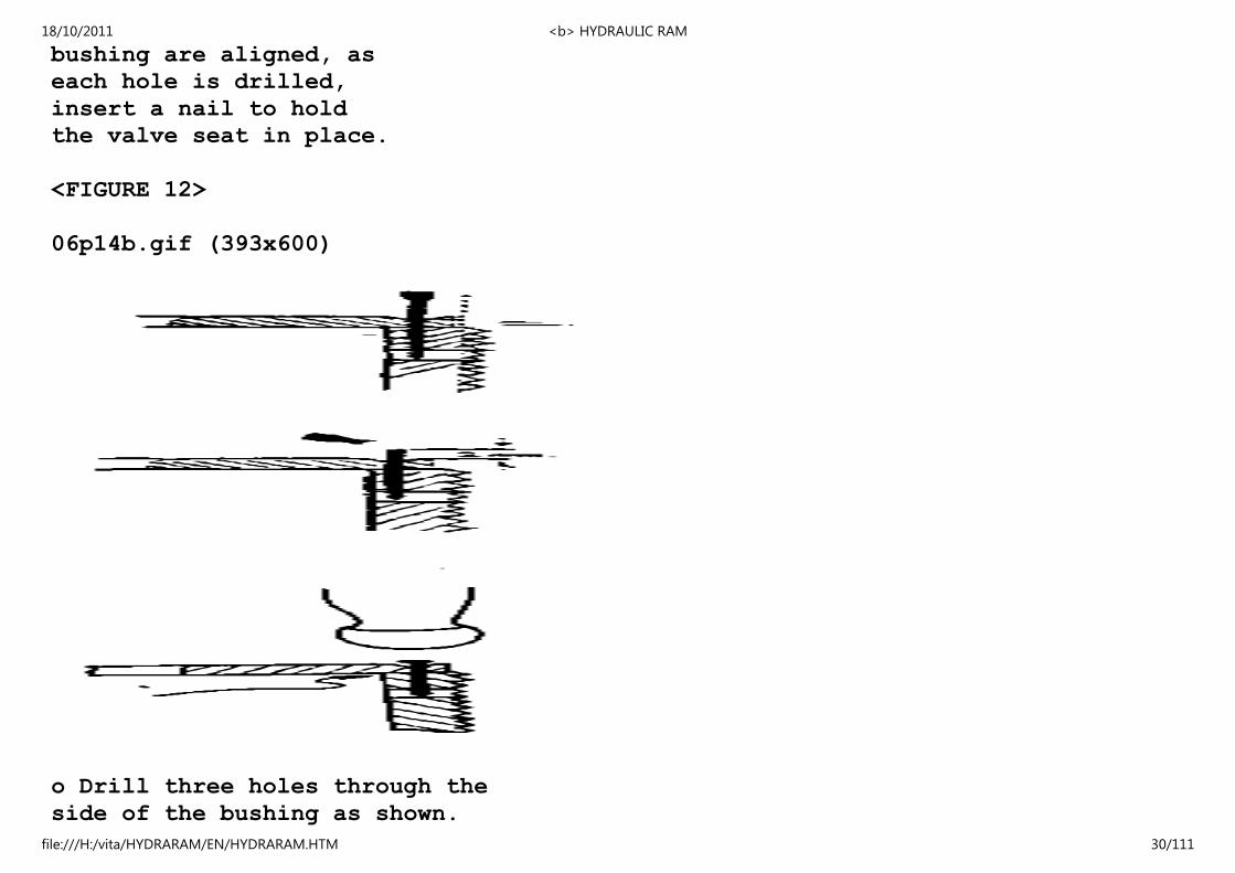
bushing are aligned, as
each hole is drilled,
insert a nail to hold
the valve seat in place.
<FIGURE 12>
06p14b.gif (393x600)
o Drill three holes through the
side of the bushing as shown.
18/10/2011 <b> HYDRAULIC RAM
file:///H:/vita/HYDRARAM/EN/HYDRARAM.HTM 30/111
Use a drill several times
larger than nails.
o Put the valve seat and nails in
place. Make sure that the outside
edge of the valve set does
not extend beyond the root of
the threads. Check this by
screwing the reducer bushing
(with the valve seat in place)
into a 3" tee--feel if there
is any resistance as it is
screwed in. File any portion
that extends beyond.
o Cut off the upper portion of
each of the three nails as
shown.
o Prepare the surfaces of the
valve seat and reducer bushing
to be glued (remove any grease
and roughen the surfaces).
o Apply epoxy (D) on nails and on
surfaces that touch and hammer
nails with a ball peen hammer
to make rivet heads.
18/10/2011 <b> HYDRAULIC RAM
file:///H:/vita/HYDRARAM/EN/HYDRARAM.HTM 31/111
o Hammer a larger nail with a rounded point
through the three holes as shown to
bend the foot of the nail rivets. Do not
bend the nail rivets too much because
they may break.
o File the heads of the nail rivets when
the epoxy has dried. Avoid making deep
scratches on the valve seat.
<FIGURE 13>
06p15a.gif (486x486)
18/10/2011 <b> HYDRAULIC RAM
file:///H:/vita/HYDRARAM/EN/HYDRARAM.HTM 32/111
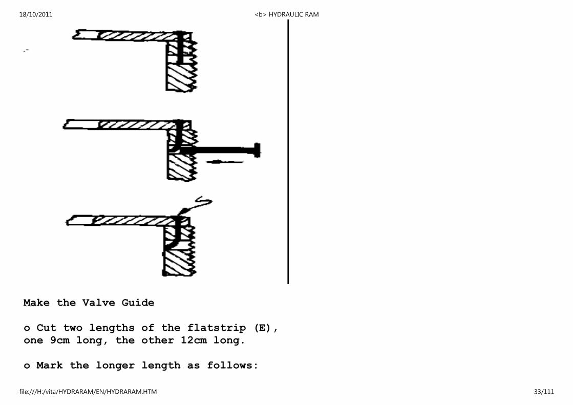
Make the Valve Guide
o Cut two lengths of the flatstrip (E),
one 9cm long, the other 12cm long.
o Mark the longer length as follows:
18/10/2011 <b> HYDRAULIC RAM
file:///H:/vita/HYDRARAM/EN/HYDRARAM.HTM 33/111

<FIGURE 14>
06p15b.gif (486x486)
o Use a vise and hammer to bend this longer length.
Note the position of the marks.
18/10/2011 <b> HYDRAULIC RAM
file:///H:/vita/HYDRARAM/EN/HYDRARAM.HTM 34/111

(a) Always keep
this piece
at right angles
to the vise.
(b) Reverse the
strip's position
in the
vise. Make
the second
bend.
(c) Place strip in
vise as shown
and make the
third bend.
(d) Put the opposite
end of the strip
in the vise for
the fourth bend.
<FIGURE 15>
06p16.gif (486x486)
18/10/2011 <b> HYDRAULIC RAM
file:///H:/vita/HYDRARAM/EN/HYDRARAM.HTM 35/111
After bending this long piece, it should fit flat over the
shorter, flat piece. If not, rebend until it does.
<FIGURE 16>
06p17a.gif (437x437)
18/10/2011 <b> HYDRAULIC RAM
file:///H:/vita/HYDRARAM/EN/HYDRARAM.HTM 36/111

Fasten the Valve Guide to the Reducer Bushing
o Drill a hole the size of the nails (C) in the center
of each end of the valve guide so that each hole ends
up above the center of the wall of the reducer bushing
(see drawing below). Make a slight depression around
these holes.
<FIGURE 17>
18/10/2011 <b> HYDRAULIC RAM
file:///H:/vita/HYDRARAM/EN/HYDRARAM.HTM 37/111

06p17b.gif (285x486)
o Place the flat portion of the valve-guide as close to
the center of the bushing as possible and continue
drilling the holes into the bushing ...
... then drill
through the wall
of the bushing as
done previously.
<FIGURE 18>
06p17c.gif (167x437)
18/10/2011 <b> HYDRAULIC RAM
file:///H:/vita/HYDRARAM/EN/HYDRARAM.HTM 38/111
o Cut the nails to the proper
length and prepare the surfaces
to be glued as before. Glue
the two portions of the valve
guide to the bushing with epoxy.
Hammer rivet heads on the nails.
Bend the foot of the nail rivets
as before. Set aside to dry.
<FIGURE 19>
06p18a.gif (285x285)
18/10/2011 <b> HYDRAULIC RAM
file:///H:/vita/HYDRARAM/EN/HYDRARAM.HTM 39/111

Drill the Valve Guide
o Locate the center of the valve guide by placing the
bushing on a flat surface pushed up against a spacer
block and a square.
This point is the center of
the valve guide if ...
<FIGURE 20>
06p18b.gif (317x317)
18/10/2011 <b> HYDRAULIC RAM
file:///H:/vita/HYDRARAM/EN/HYDRARAM.HTM 40/111
... the distance between
this point and the
square is constant as
the bushing is held
against the block and
rotated.
o Center punch the center and drill
a hole about 0.25mm (.010") larger
than the diameter of the shank of
the 9mm (3/8") bolt (F) through
both portions of the valve-guide.
Make sure that the valve seat lies
compleltely flat on the drill
18/10/2011 <b> HYDRAULIC RAM
file:///H:/vita/HYDRARAM/EN/HYDRARAM.HTM 41/111

press table so that the drill is
perpendicular to the valve seat.
<FIGURE 21>
06p19a.gif (353x353)
o Through a piece of scrap metal the
same thickness as used in making
the valve guide, drill a hole and
insert the 9mm (3/8") bolt almost
all the way. Measure the maximum
18/10/2011 <b> HYDRAULIC RAM
file:///H:/vita/HYDRARAM/EN/HYDRARAM.HTM 42/111

distance the end of the bolt can
move from side to side if the
piece of scrap metal is held firm.
If a 3mm flat strip was used to
make the valve-guide, this distance
should be 2 - 3cm if the
hole is of the proper size. If
the proper drill is not available,
an undersized hole can be filed
larger. Be very careful not to
overfile the hole.
(A micrometer or vernier caliper, if available, may
be used to select the right size drill).
<FIGURE 22>
06p19b.gif (285x285)
18/10/2011 <b> HYDRAULIC RAM
file:///H:/vita/HYDRARAM/EN/HYDRARAM.HTM 43/111
Make the Valve Bushing
o Use the 1.27cm (1/2") bolt or round rod (G).
o Drill a hole in the center
whose diameter is equal to
the diameter of the threaded
portion of the 9mm
(3/8") bolt (F).
<FIGURE 23>
06p19c.gif (230x230)
18/10/2011 <b> HYDRAULIC RAM
file:///H:/vita/HYDRARAM/EN/HYDRARAM.HTM 44/111
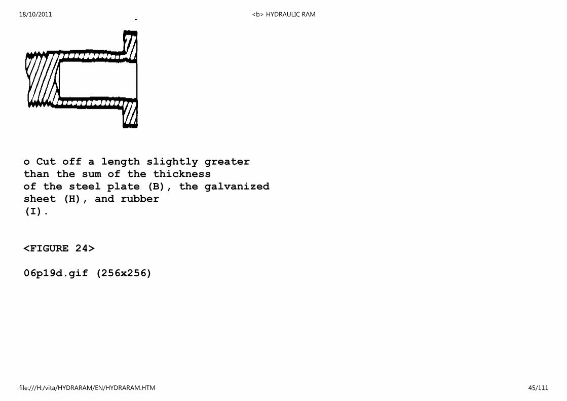
o Cut off a length slightly greater
than the sum of the thickness
of the steel plate (B), the galvanized
sheet (H), and rubber
(I).
<FIGURE 24>
06p19d.gif (256x256)
18/10/2011 <b> HYDRAULIC RAM
file:///H:/vita/HYDRARAM/EN/HYDRARAM.HTM 45/111

Galvanized Disc
o Draw a circle with a diameter of 4.0cm on a piece of galvanized
sheet (H).
<FIGURE 25>
06p20a.gif (186x186)
18/10/2011 <b> HYDRAULIC RAM
file:///H:/vita/HYDRARAM/EN/HYDRARAM.HTM 46/111
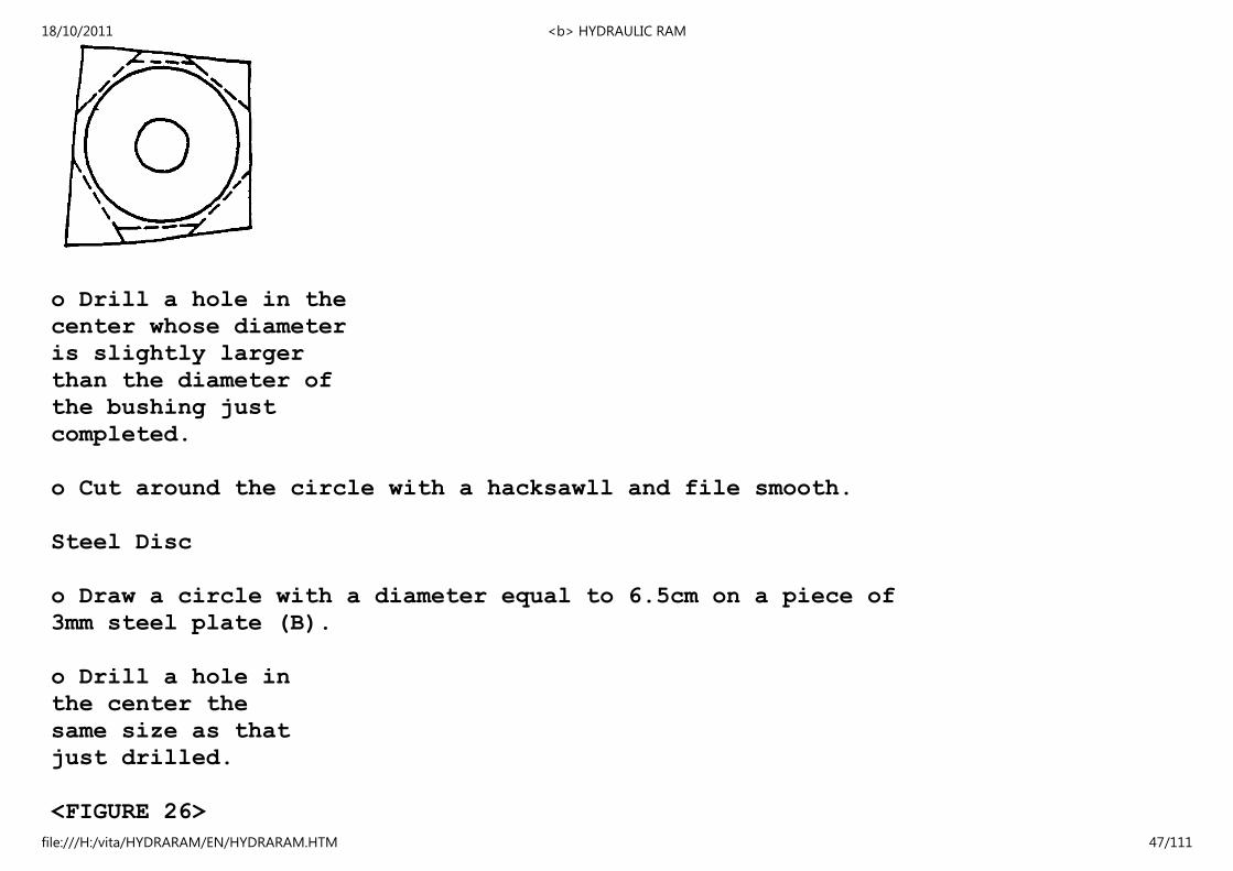
o Drill a hole in the
center whose diameter
is slightly larger
than the diameter of
the bushing just
completed.
o Cut around the circle with a hacksawll and file smooth.
Steel Disc
o Draw a circle with a diameter equal to 6.5cm on a piece of
3mm steel plate (B).
o Drill a hole in
the center the
same size as that
just drilled.
<FIGURE 26>
18/10/2011 <b> HYDRAULIC RAM
file:///H:/vita/HYDRARAM/EN/HYDRARAM.HTM 47/111
06p20b.gif (186x186)
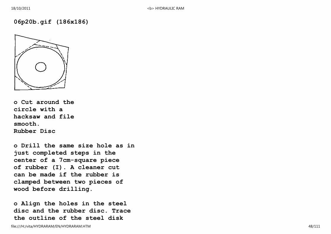
o Cut around the
circle with a
hacksaw and file
smooth.
Rubber Disc
o Drill the same size hole as in
just completed steps in the
center of a 7cm-square piece
of rubber (I). A cleaner cut
can be made if the rubber is
clamped between two pieces of
wood before drilling.
o Align the holes in the steel
disc and the rubber disc. Trace
the outline of the steel disk
18/10/2011 <b> HYDRAULIC RAM
file:///H:/vita/HYDRARAM/EN/HYDRARAM.HTM 48/111
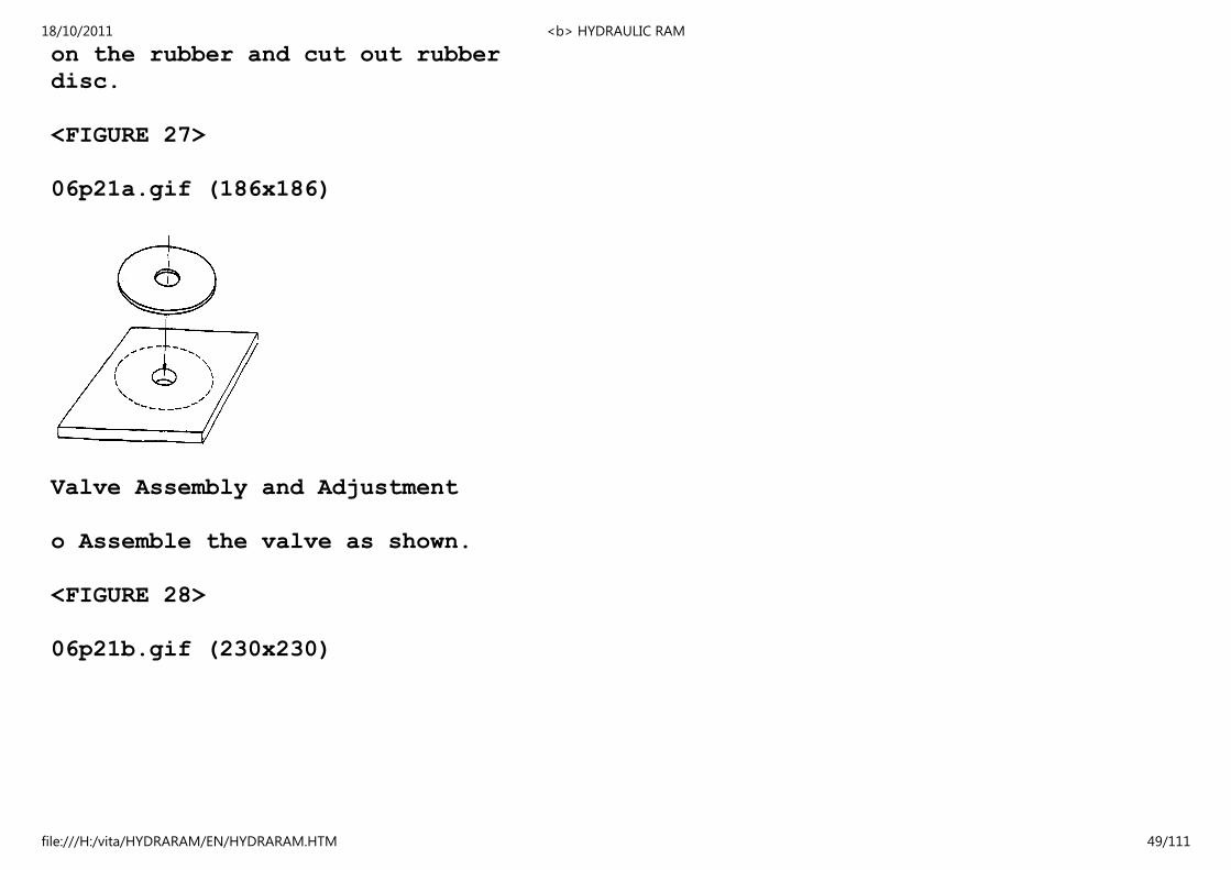
on the rubber and cut out rubber
disc.
<FIGURE 27>
06p21a.gif (186x186)
Valve Assembly and Adjustment
o Assemble the valve as shown.
<FIGURE 28>
06p21b.gif (230x230)
18/10/2011 <b> HYDRAULIC RAM
file:///H:/vita/HYDRARAM/EN/HYDRARAM.HTM 49/111
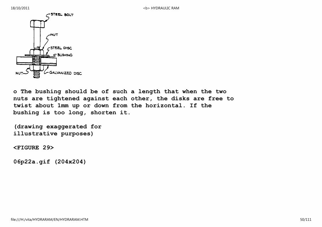
o The bushing should be of such a length that when the two
nuts are tightened against each other, the disks are free to
twist about 1mm up or down from the horizontal. If the
bushing is too long, shorten it.
(drawing exaggerated for
illustrative purposes)
<FIGURE 29>
06p22a.gif (204x204)
18/10/2011 <b> HYDRAULIC RAM
file:///H:/vita/HYDRARAM/EN/HYDRARAM.HTM 50/111
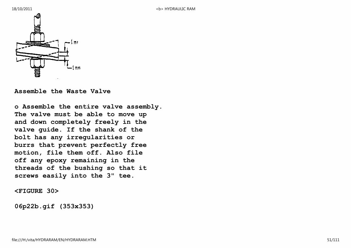
Assemble the Waste Valve
o Assemble the entire valve assembly.
The valve must be able to move up
and down completely freely in the
valve guide. If the shank of the
bolt has any irregularities or
burrs that prevent perfectly free
motion, file them off. Also file
off any epoxy remaining in the
threads of the bushing so that it
screws easily into the 3" tee.
<FIGURE 30>
06p22b.gif (353x353)
18/10/2011 <b> HYDRAULIC RAM
file:///H:/vita/HYDRARAM/EN/HYDRARAM.HTM 51/111
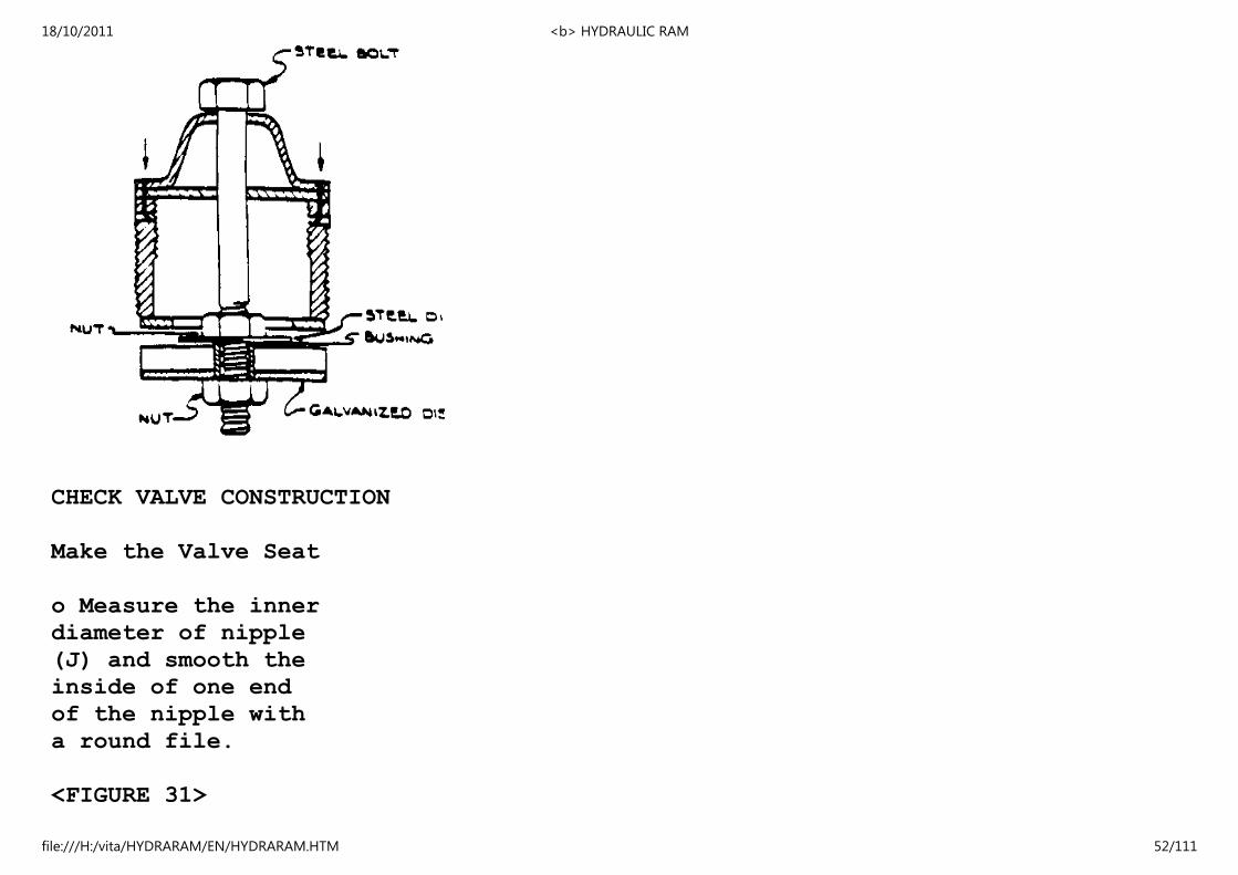
CHECK VALVE CONSTRUCTION
Make the Valve Seat
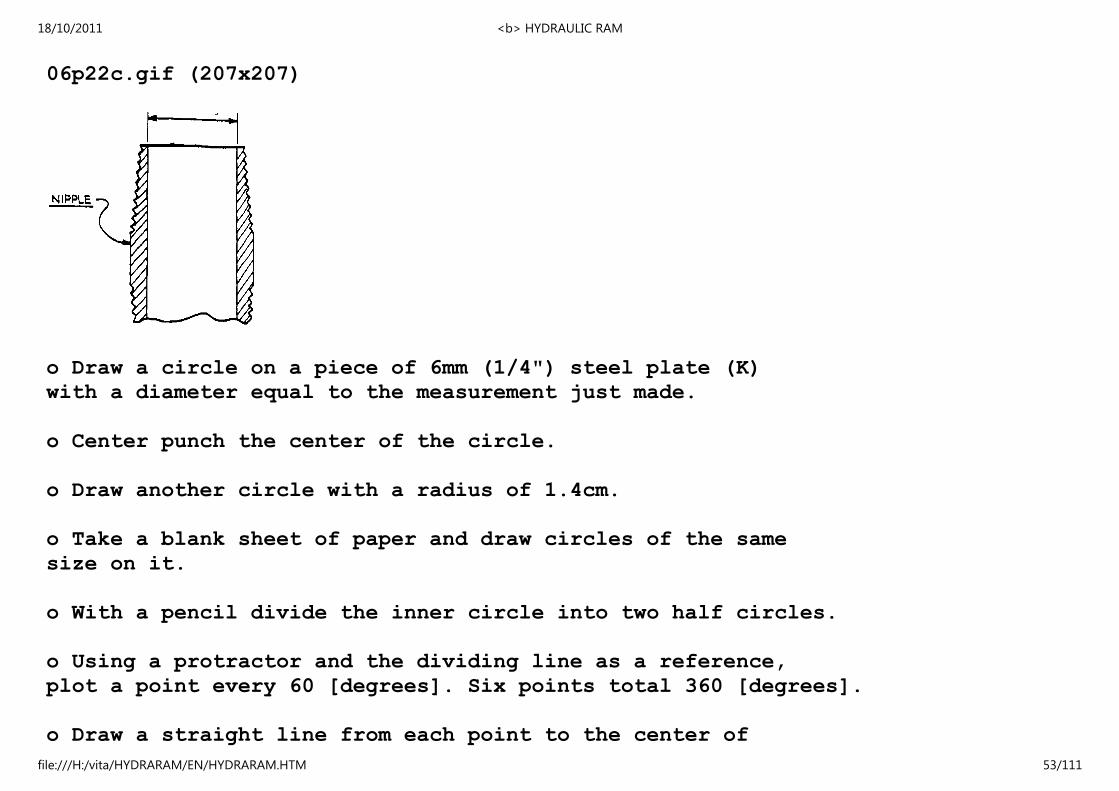
o Measure the inner
diameter of nipple
(J) and smooth the
inside of one end
of the nipple with
a round file.
<FIGURE 31>
18/10/2011 <b> HYDRAULIC RAM
file:///H:/vita/HYDRARAM/EN/HYDRARAM.HTM 52/111
06p22c.gif (207x207)
o Draw a circle on a piece of 6mm (1/4") steel plate (K)
with a diameter equal to the measurement just made.
o Center punch the center of the circle.
o Draw another circle with a radius of 1.4cm.
o Take a blank sheet of paper and draw circles of the same
size on it.
o With a pencil divide the inner circle into two half circles.
o Using a protractor and the dividing line as a reference,
plot a point every 60 [degrees]. Six points total 360 [degrees].
o Draw a straight line from each point to the center of
18/10/2011 <b> HYDRAULIC RAM
file:///H:/vita/HYDRARAM/EN/HYDRARAM.HTM 53/111
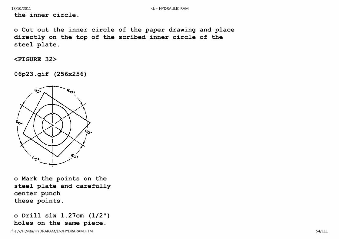
the inner circle.
o Cut out the inner circle of the paper drawing and place
directly on the top of the scribed inner circle of the
steel plate.
<FIGURE 32>
06p23.gif (256x256)
o Mark the points on the
steel plate and carefully
center punch
these points.
o Drill six 1.27cm (1/2")
holes on the same piece.
18/10/2011 <b> HYDRAULIC RAM
file:///H:/vita/HYDRARAM/EN/HYDRARAM.HTM 54/111
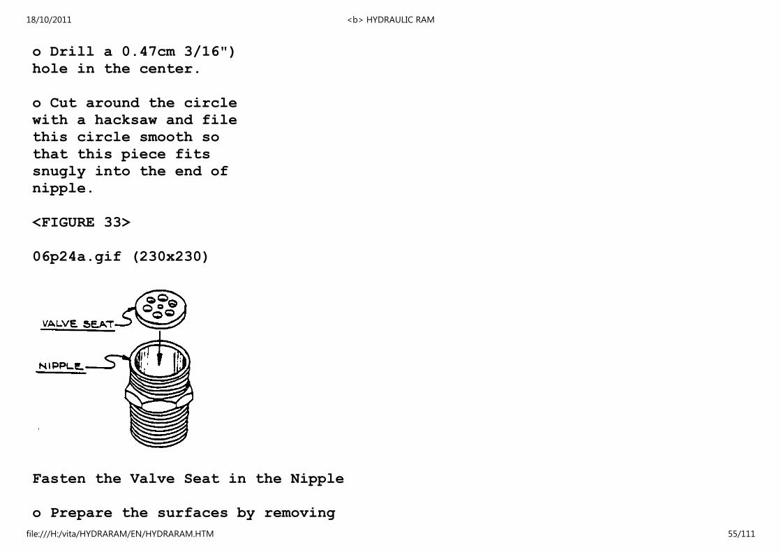
o Drill a 0.47cm 3/16")
hole in the center.
o Cut around the circle
with a hacksaw and file
this circle smooth so
that this piece fits
snugly into the end of
nipple.
<FIGURE 33>
06p24a.gif (230x230)
Fasten the Valve Seat in the Nipple
o Prepare the surfaces by removing
18/10/2011 <b> HYDRAULIC RAM
file:///H:/vita/HYDRARAM/EN/HYDRARAM.HTM 55/111

any grease and glue from the
valve seat so that it is flush
with the the top of the nipple.
o Set the nipple upside down on a
flat surface to dry.
<FIGURE 34>
06p24b.gif (207x207)
o Using the drill press,
drill three holes the
diameter of the nails
(C) partially through
the valve seat. Be
sure the epoxy is dry
first.
18/10/2011 <b> HYDRAULIC RAM
file:///H:/vita/HYDRARAM/EN/HYDRARAM.HTM 56/111
<FIGURE 35>
06p25a.gif (230x230)
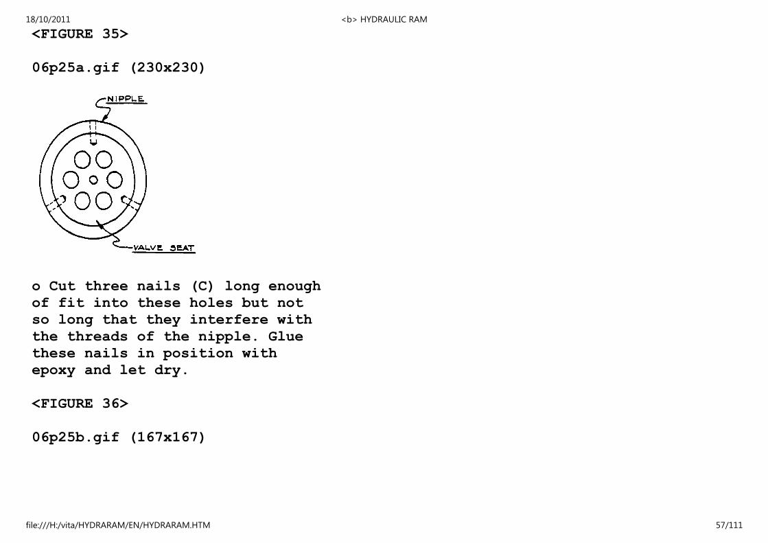
o Cut three nails (C) long enough
of fit into these holes but not
so long that they interfere with
the threads of the nipple. Glue
these nails in position with
epoxy and let dry.
<FIGURE 36>
06p25b.gif (167x167)
18/10/2011 <b> HYDRAULIC RAM
file:///H:/vita/HYDRARAM/EN/HYDRARAM.HTM 57/111
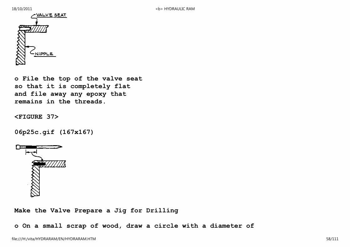
o File the top of the valve seat
so that it is completely flat
and file away any epoxy that
remains in the threads.
<FIGURE 37>
06p25c.gif (167x167)
Make the Valve Prepare a Jig for Drilling
o On a small scrap of wood, draw a circle with a diameter of
18/10/2011 <b> HYDRAULIC RAM
file:///H:/vita/HYDRARAM/EN/HYDRARAM.HTM 58/111
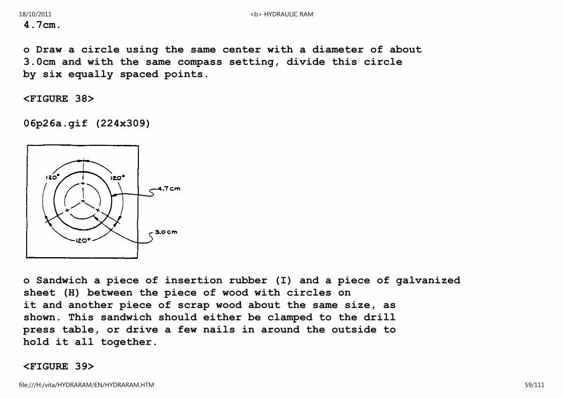
4.7cm.
o Draw a circle using the same center with a diameter of about
3.0cm and with the same compass setting, divide this circle
by six equally spaced points.
<FIGURE 38>
06p26a.gif (224x309)
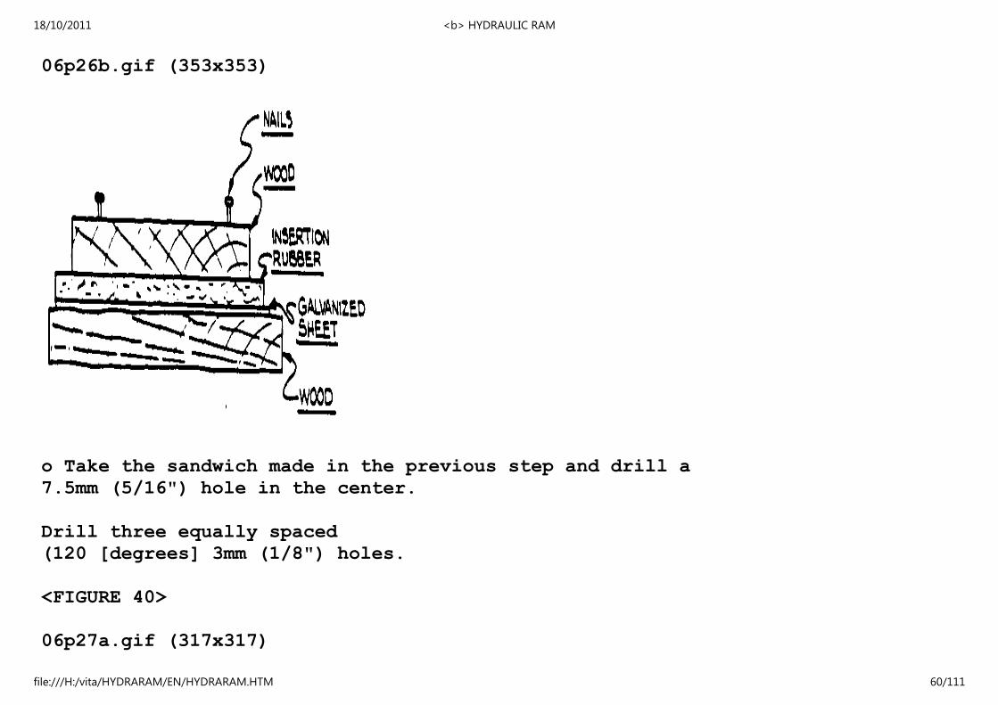
o Sandwich a piece of insertion rubber (I) and a piece of galvanized
sheet (H) between the piece of wood with circles on
it and another piece of scrap wood about the same size, as
shown. This sandwich should either be clamped to the drill
press table, or drive a few nails in around the outside to
hold it all together.
<FIGURE 39>
18/10/2011 <b> HYDRAULIC RAM
file:///H:/vita/HYDRARAM/EN/HYDRARAM.HTM 59/111
06p26b.gif (353x353)
o Take the sandwich made in the previous step and drill a
7.5mm (5/16") hole in the center.
Drill three equally spaced
(120 [degrees] 3mm (1/8") holes.
<FIGURE 40>
06p27a.gif (317x317)
18/10/2011 <b> HYDRAULIC RAM
file:///H:/vita/HYDRARAM/EN/HYDRARAM.HTM 60/111

o Partially redrill the three 3mm (1/8")
holes a short way into the rubber to
countersink the head the head of the
screws (M).
<FIGURE 41>
06p27b.gif (281x281)
18/10/2011 <b> HYDRAULIC RAM
file:///H:/vita/HYDRARAM/EN/HYDRARAM.HTM 61/111
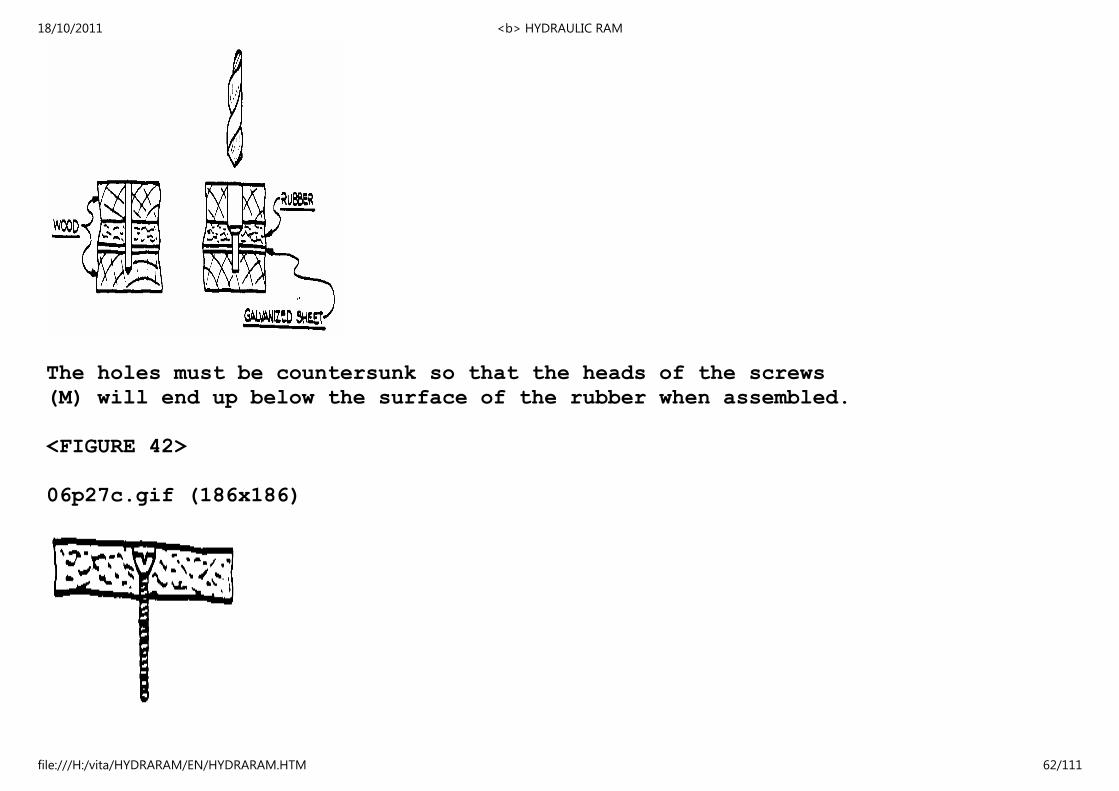
The holes must be countersunk so that the heads of the screws
(M) will end up below the surface of the rubber when assembled.
<FIGURE 42>
06p27c.gif (186x186)
18/10/2011 <b> HYDRAULIC RAM
file:///H:/vita/HYDRARAM/EN/HYDRARAM.HTM 62/111
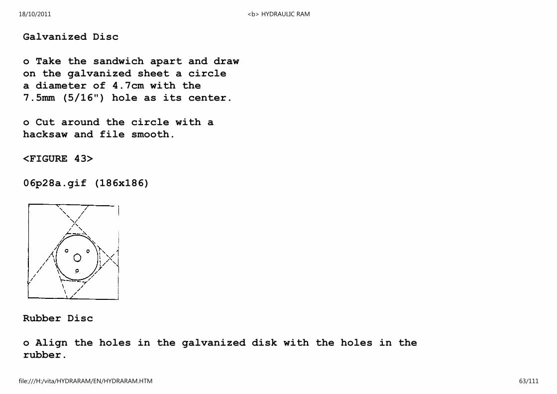
Galvanized Disc
o Take the sandwich apart and draw
on the galvanized sheet a circle
a diameter of 4.7cm with the
7.5mm (5/16") hole as its center.
o Cut around the circle with a
hacksaw and file smooth.
<FIGURE 43>
06p28a.gif (186x186)
Rubber Disc
o Align the holes in the galvanized disk with the holes in the
rubber.
18/10/2011 <b> HYDRAULIC RAM
file:///H:/vita/HYDRARAM/EN/HYDRARAM.HTM 63/111

o Trace its outline on the
rubber.
o Cut the rubber slightly
larger than this outline.
<FIGURE 44>
06p28b.gif (167x167)
Assembly
o Assemble the valve from the galvanized and rubber discs. Push
the three 3mm (1/8") bolts (M) all the way into the depressed
holes in the rubber and loosely put on the nuts. Tighten
them finger tight. Do not use a screwdriver to tighten the
bolts. If they are tightened too much, the rubber will not
remain flat.
o Put a drop of epoxy adhesive on the nuts to hold them in
18/10/2011 <b> HYDRAULIC RAM
file:///H:/vita/HYDRARAM/EN/HYDRARAM.HTM 64/111
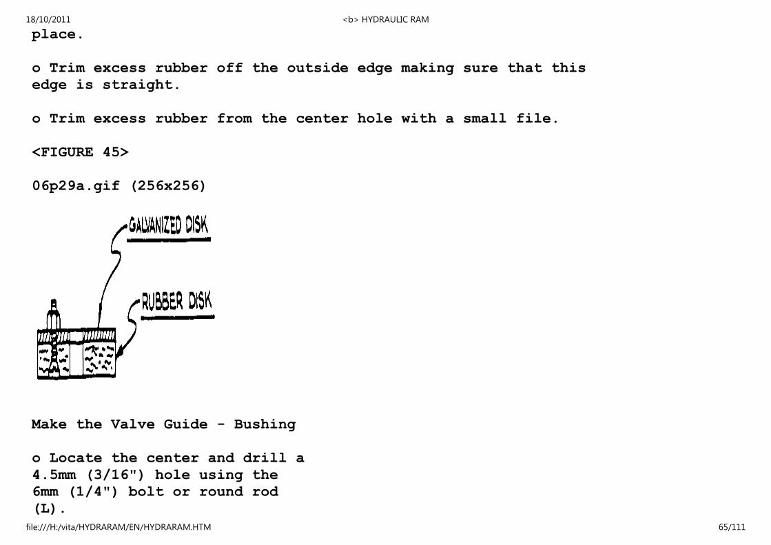
place.
o Trim excess rubber off the outside edge making sure that this
edge is straight.
o Trim excess rubber from the center hole with a small file.
<FIGURE 45>
06p29a.gif (256x256)
Make the Valve Guide - Bushing
o Locate the center and drill a
4.5mm (3/16") hole using the
6mm (1/4") bolt or round rod
(L).
18/10/2011 <b> HYDRAULIC RAM
file:///H:/vita/HYDRARAM/EN/HYDRARAM.HTM 65/111
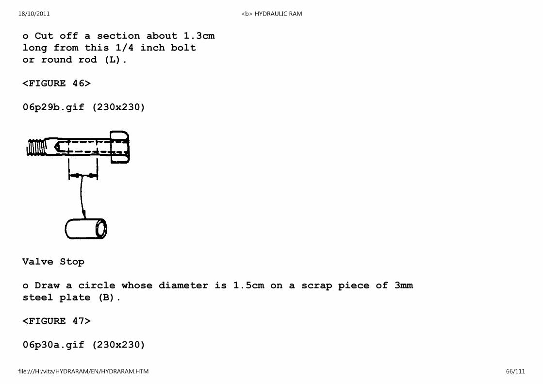
o Cut off a section about 1.3cm
long from this 1/4 inch bolt
or round rod (L).
<FIGURE 46>
06p29b.gif (230x230)
Valve Stop
o Draw a circle whose diameter is 1.5cm on a scrap piece of 3mm
steel plate (B).
<FIGURE 47>
06p30a.gif (230x230)
18/10/2011 <b> HYDRAULIC RAM
file:///H:/vita/HYDRARAM/EN/HYDRARAM.HTM 66/111

o Punch the center and drill a
4.5mm (3/16") hole.
o Cut around the circle with a
hacksaw and file smooth, making
a steel disc.
Assemble the Check Valve
o Put together the entire valve assembly as shown below.
The valve should
move up and down
very freely.
<FIGURE 48>
06p30b.gif (281x281)
18/10/2011 <b> HYDRAULIC RAM
file:///H:/vita/HYDRARAM/EN/HYDRARAM.HTM 67/111
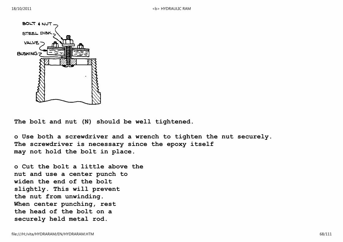
The bolt and nut (N) should be well tightened.
o Use both a screwdriver and a wrench to tighten the nut securely.
The screwdriver is necessary since the epoxy itself
may not hold the bolt in place.
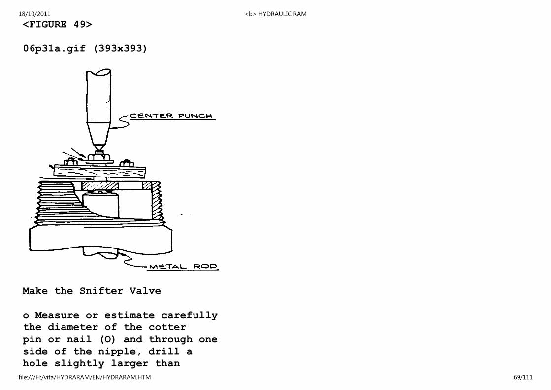
o Cut the bolt a little above the
nut and use a center punch to
widen the end of the bolt
slightly. This will prevent
the nut from unwinding.
When center punching, rest
the head of the bolt on a
securely held metal rod.
18/10/2011 <b> HYDRAULIC RAM
file:///H:/vita/HYDRARAM/EN/HYDRARAM.HTM 68/111
<FIGURE 49>
06p31a.gif (393x393)
Make the Snifter Valve
o Measure or estimate carefully
the diameter of the cotter
pin or nail (O) and through one
side of the nipple, drill a
hole slightly larger than
18/10/2011 <b> HYDRAULIC RAM
file:///H:/vita/HYDRARAM/EN/HYDRARAM.HTM 69/111
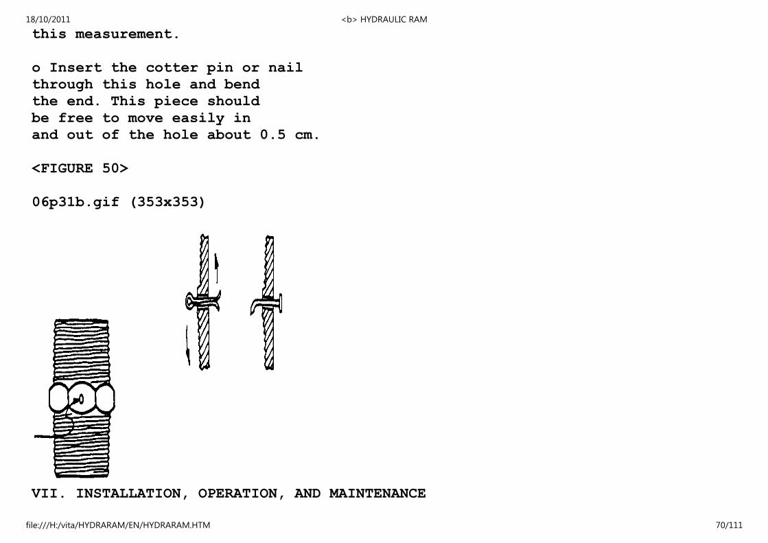
this measurement.
o Insert the cotter pin or nail
through this hole and bend
the end. This piece should
be free to move easily in
and out of the hole about 0.5 cm.
<FIGURE 50>
06p31b.gif (353x353)
VII. INSTALLATION, OPERATION, AND MAINTENANCE
18/10/2011 <b> HYDRAULIC RAM
file:///H:/vita/HYDRARAM/EN/HYDRARAM.HTM 70/111

The pipe fittings and the two valves should be assembled as
illustrated previously. The nipple is installed so that the
check valve is on top. Teflon tape or a joint compound should
be used on all threads before screwing the fittings together.
The joints at both ends of the half-meter length of pipe must be
completely leakproof, otherwise the pump will fail to operate
properly. Probably the easiest way to verify that the joints
are leakproof is to observe the joints for signs of leaking
while the pump is in operation. While not as critical, all
other joints should also be water tight.
<FIGURE 51>
06p33.gif (486x486)
18/10/2011 <b> HYDRAULIC RAM
file:///H:/vita/HYDRARAM/EN/HYDRARAM.HTM 71/111

When installed on site, the body of the ram should be secured
firmly to the ground and both the waste and check valves must be
maintained in a vertical position.
The drive pipe should have a strainer attached made of 1.5cm
screen wire, hardware cloth, or anything suitable. The strainer
18/10/2011 <b> HYDRAULIC RAM
file:///H:/vita/HYDRARAM/EN/HYDRARAM.HTM 72/111

keeps out the trash, frogs, leaves, and fish, any of which will
stop the ram if they get inside. The drive pipe should be 4cm
diameter or larger and, if possible, new, solidly put together,
straight, and well supported throughout its length. A gate valve
on the drive pipe about 1.5m (4 feet) from the ram is a great
convenience but not necessary. Another gate valve on the delivery
pipe is helpful to avoid draining the delivery pipe whenever
the ram is cleaned. The ram should not be welded to the
delivery and drive pipes so it can be removed for cleaning. If
you use two or more rams, each must have separate drive pipes but
the delivery pipes can be joined, provided the pipe is large
enough to carry the water.
The delivery pipe should start from the ram with about two
lengths of 2.5cm galvanized iron pipe. After this, 2cm pipe can
be used. The iron pipe will give the ram better support, but
plastic pipe is smoother inside and can be a size smaller than
the iron pipe. Although plastic pipe can be used and is
cheaper, it must be protected from mechanical injury and sunlight.
It is best to have all the water pumped by the ram to
run directly into a storage tank, to be used from there.
Rams have an exceptionally good reputation for trouble free
operation and are practically maintenance-free. The way in
which the necessary maintenance is arranged depends very much on
who is available to carry it out. There should be someone
familiar with ram operations who could have a look at the ram at
least once every week.
18/10/2011 <b> HYDRAULIC RAM
file:///H:/vita/HYDRARAM/EN/HYDRARAM.HTM 73/111
Tuning and adjustment of valves and bolts may need to be done
more frequently with this ram than with some commercial models
made from purpose-designed alloys and components. The need for
maintenance may become greater as the ram gets older.
Below are some steps that should be taken on a regular basis for
trouble-free maintenance. Start with this list when the ram is
not working properly.
o See that the clack valve closes squarely, evenly, and
completely. If it does not, the clack spring may have
been bent somehow, and will have to be straightened.
o See that the clack valve does not rub on the front,
side, or back of the valve body inside.
o Check for trash in the ram, delivery valve, or snifter
hole.
o Check to see that the air dome is not filled with
water. It must not be full of water or the ram will
knock loudly and may break something. The snifter
lets in a bit of air between each of the strokes and
this keeps the dome full of compressed air.
o Check rubber clack and delivery valve for wear or
looseness.
o If drive water is in short supply, speed up the stroke
18/10/2011 <b> HYDRAULIC RAM
file:///H:/vita/HYDRARAM/EN/HYDRARAM.HTM 74/111

by loosening the spring tension and shorten the stroke
by lowering the stroke adjusting bolt. More water is
delivered by a faster stroke and continuous running
than a slower stroke. (See also p. 46.)
<FIGURE 52>
06p35.gif (317x317)
o Check for leaks in the drive pipe. If air bubbles
come out of the drive pipe after it has been stopped
for a while it is leaking air. Air in the drive pipe
causes the ram action to become inefficient.
18/10/2011 <b> HYDRAULIC RAM
file:///H:/vita/HYDRARAM/EN/HYDRARAM.HTM 75/111

o Clean the ram once in a while. Protect it from outside
injury and inquisitive children.
o When the ram runs out of water, it will usually
stop, remain open, and lose all the water available
until it is closed again. You can listen at the
storage tank to hear if it is still running; and, if
it isn't, go to the ram and close the drive pipe
until water has accumulated in the cistern.
o Long delivery distances require a larger pipe to reduce
friction (known as pressure drop).
o A cistern (container) is a good thing to have at the
top of the drive pipe to let dirt in the water settle.
The outlet from the cistern to the ram should be a
foot or so above the bottom to allow room for dirt to
settle. A cleaning drain in the bottom of the cistern
is a good feature. The cistern should be cleaned
periodically.
The actual delivery rate can be changed somewhat by varying this
stroke. This can be done either by:
<FIGURE 53>
06p36.gif (207x437)
18/10/2011 <b> HYDRAULIC RAM
file:///H:/vita/HYDRARAM/EN/HYDRARAM.HTM 76/111
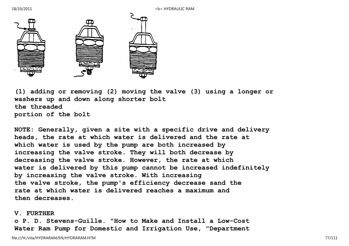
(1) adding or removing (2) moving the valve (3) using a longer or
washers up and down along shorter bolt
the threaded
portion of the bolt
NOTE: Generally, given a site with a specific drive and delivery
heads, the rate at which water is delivered and the rate at
which water is used by the pump are both increased by
increasing the valve stroke. They will both decrease by
decreasing the valve stroke. However, the rate at which
water is delivered by this pump cannot be increased indefinitely
by increasing the valve stroke. With increasing
the valve stroke, the pump's efficiency decrease sand the
rate at which water is delivered reaches a maximum and
then decreases.
V. FURTHER
o P. D. Stevens-Guille. "How to Make and Install a Low-Cost
Water Ram Pump for Domestic and Irrigation Use, "Department
18/10/2011 <b> HYDRAULIC RAM
file:///H:/vita/HYDRARAM/EN/HYDRARAM.HTM 77/111
of Mechanical Engineering, University of Cape Town, August
1977. Instructions for building a hydraulic ram pump from
pipe fittings and valves. Contains some information on how
it works and how to set it up. Includes parts of lists,
diagrams, and tables. Not comprehensive, but clearly written.
o W. H. Sheldon. "The Hydraulic Ram," Michigan State College
Extension Service, Michican State College of Agriculture
and Applied Science, Michigan State University, East
Lansing, Michigan 48823 USA. Bulletin 171, July 1943. Has
some basic information on ram operation and installation.
some good illustrations of different methods of installing
hydraulic ram systems. Also list of information required
for installing a ram.
o T. G. Behrends. "The Farm Water Supply Part II. The Use of
the Hydraulic Ram," Cornell University Extension Bulletin
145, June 1926. New York State College of Agriculture,
Cornell University, Ithaca, New York USA. A fairly comprehensive,
well-illustrated booklet. Includes basic
information as well as sections on storage tanks, different
types of rams, etc. Although rather dated, this is one of
the most useful booklets on the subject.
APPENDIX I
ADDITIONAL PERFORMANCE CONSIDERATIONS
The following pages provide guidelines on the ram and its performance.
Several of the suggestions for design changes, such
18/10/2011 <b> HYDRAULIC RAM
file:///H:/vita/HYDRARAM/EN/HYDRARAM.HTM 78/111
as those relating to the possible use of plastic pipe and to
work with higher heads, should be read carefully before construction
begins.
TEST INSTALLATION
This hydraulic ram was installed for testing as illustrated
below. This level of water in the standpipe was maintained at
the desired drive head. The drive pipe consisted of about two
lengths of galvanized iron pipe leading to the pump. Variable
delivery heads were simulated by imposing a known pressure (corresponding
to the desired delivery head) on the output.
<FIGURE 54>
06p39.gif (534x534)
18/10/2011 <b> HYDRAULIC RAM
file:///H:/vita/HYDRARAM/EN/HYDRARAM.HTM 79/111

PERFORMANCE DATA
The data presented in the graph on the following page are for
the ram operating with a 10mm valve stroke. This valve stroke
is the distance the waste valve is permitted to move up and
18/10/2011 <b> HYDRAULIC RAM
file:///H:/vita/HYDRARAM/EN/HYDRARAM.HTM 80/111

down. It can easily be adjusted either to increase or to decrease
the rate at which water is used and the rate at which
water is delivered by the pump from the values from the graph.
Adjustment of the valve stroke is explained on page 36.
HOW TO USE THE GRAPH
Suppose that a ram with a 1-1/2" drive pipe is to be located so
that the drive head down to the pump is 3.0 meters and the water
has to be pumped up to a height of 35 meters above the pump.
(Note that the actual length of the delivery pipe may be much
longer than 35 meters.)
<FIGURE 55>
06p40.gif (540x540)
18/10/2011 <b> HYDRAULIC RAM
file:///H:/vita/HYDRARAM/EN/HYDRARAM.HTM 81/111

o Find the delivery head along the bottom of the graph.
o Move straight up until the appropriate curve for a drive
head of 3.0 meters is reached. This locates the operating
18/10/2011 <b> HYDRAULIC RAM
file:///H:/vita/HYDRARAM/EN/HYDRARAM.HTM 82/111

point.
o To determine the delivery rate, read the scale directly to
the left (about 2.2 liters/minute) or to the right (about
3,200 liters/day).
o To obtain an estimate of how much water will be used by
the pump, note the position of the operating point between
the two numbers at the end points of the curve and interpolate
(about 35 liters/minute).
<FIGURE 56>
06p41.gif (600x600)
18/10/2011 <b> HYDRAULIC RAM
file:///H:/vita/HYDRARAM/EN/HYDRARAM.HTM 83/111

The exact drive and delivery rates for another installation
depend on the length and diameter of the drive pipe and delivery
18/10/2011 <b> HYDRAULIC RAM
file:///H:/vita/HYDRARAM/EN/HYDRARAM.HTM 84/111

pipe. A good estimate of the pump's performance should still be
available from the values of the graph.
The graphs below are included to illustrate a typical variation
of drive and delivery rates, efficiency, and frequency (strokes
per minute) with valve stroke.
<FIGURE 57>
06p42.gif (600x600)
18/10/2011 <b> HYDRAULIC RAM
file:///H:/vita/HYDRARAM/EN/HYDRARAM.HTM 85/111

EFFECTS OF OTHER VARIABLES
18/10/2011 <b> HYDRAULIC RAM
file:///H:/vita/HYDRARAM/EN/HYDRARAM.HTM 86/111
Size of Air Chamber
The half-meter length of 2" pipe used as the air chamber for
this ram seems to be perfectly adequate for the flows delivered
by this pump. Increasing the size of the air chamber seems to
have negligible effect on its performance.
Drive Pipe Diameter
For cost and weight efficiency, the smaller the diameter of the
drive pipe, the better. However, drive pipe diameter also affects
the ram's performance. A drive pipe with too small a
diameter restricts the flow of water to the pump with the result
that the pump delivers less water.
The graph below illustrates the effect of the diameter of the
drive pipe at the test installation on the rate at which water
is delivered by the pump. A large diameter pipe proves an advantage
only in cases where larger flows are desired.
The length of the drive pipe
also affects the ram's performance.
If a much longer drive pipe is
used, its diameter must also be
larger to keep losses down.
When low drive heads are used
(about a meter or less),
friction losses in the drive
18/10/2011 <b> HYDRAULIC RAM
file:///H:/vita/HYDRARAM/EN/HYDRARAM.HTM 87/111

pipe become more important
since there is less head
available to overcome them.
A larger diameter drive pipe
is then necessary to reduce
losses and permit sufficient
water to reach the pump. (The
reason there is no curve for a
drive head of 10 meters on the
graph on page 41, when using a
1-1/4" drive pipe, is that
there is insufficient water
flowing through to the pump to
operate it. This problem is
overcome by using a larger
diameter drive pipe.)
<FIGURE 58>
06p43.gif (486x486)
18/10/2011 <b> HYDRAULIC RAM
file:///H:/vita/HYDRARAM/EN/HYDRARAM.HTM 88/111
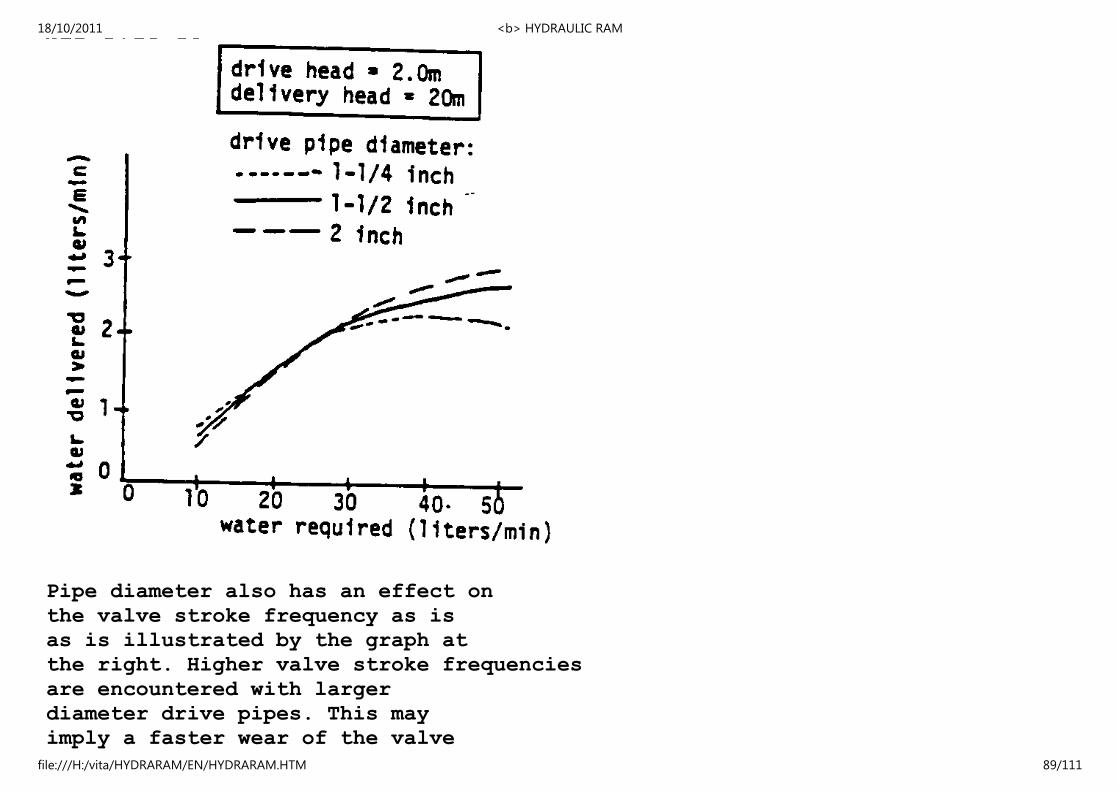
Pipe diameter also has an effect on
the valve stroke frequency as is
as is illustrated by the graph at
the right. Higher valve stroke frequencies
are encountered with larger
diameter drive pipes. This may
imply a faster wear of the valve
18/10/2011 <b> HYDRAULIC RAM
file:///H:/vita/HYDRARAM/EN/HYDRARAM.HTM 89/111

shaft and seating rubber (this is
probably of little consequence if
the parts can easily be replaced).
<FIGURE 59>
06p44.gif (486x486)
18/10/2011 <b> HYDRAULIC RAM
file:///H:/vita/HYDRARAM/EN/HYDRARAM.HTM 90/111

Mounting of the Ram
It is important to mount the ram securely so that it will remain
in its proper operating position in spite of tampering,
heavy rains, floods, etc.
Mass of the Waste Valve Plunger
18/10/2011 <b> HYDRAULIC RAM
file:///H:/vita/HYDRARAM/EN/HYDRARAM.HTM 91/111

Increasing the mass of the waste valve plunger by using larger
and therefore heavier components has the same effect on the
pump's performance as increasing the valve stroke, i.e., it
reduces the operating frequency of the ram and generally increases
both the quantity of water used by the ram and the
quantity delivered by the ram. But for low drive heads or for a
drive pipe of too small a diameter, too heavy a plunger might
prevent the operation of the pump altogether.
If operating frequencies prove too high (as might be the case
with drive heads much larger than 4 meters), the quantitiy of
water delivered by the ram would be small. Though increasing
the mass of the plunger would decrease the frequency and increase
the rate at which water is delivered, this might possibly
reduce the life of the valve because of the increased
forces as the valve closes repeatedly. For such operating
conditions, use of a spring, as explained later, would be a
better solution.
Use of PVC Drive Pipe
Several trial runs were made using a 1-1/2"-diameter, class 12
rigid PVC pressure pipe (pressure rated to a head of 120 meters).
Though it is known that the
commonly used galvanized
iron pipe is more efficient
than PVC, it was felt that
use of PVC could prove
18/10/2011 <b> HYDRAULIC RAM
file:///H:/vita/HYDRARAM/EN/HYDRARAM.HTM 92/111
advantageous on occasions
when ram components have
to be carried on foot
to remote areas.
From testing, it is
apparent that the PVC
drive pipe is slightly
less efficient. The
The graphs at the
right compare the
pump's performance using
1-1/2"-diameter drive
pipes of galvanized
iron and PVC. Note
that in the second
graph, the valve stroke
is set at 10mm and that
it is possible to
increase somewhat the
rate at which water
is delivered by
increasing this
valve stroke.
These data imply that
rigid pressure PVC pipe
could be used for a drive
pipe if necessary. However,
18/10/2011 <b> HYDRAULIC RAM
file:///H:/vita/HYDRARAM/EN/HYDRARAM.HTM 93/111
since durability
tests have not been
carried out with the
PVC drive pipe, it is
difficult to state here
how much, if any, the
life of the pipe would be
reduced by the operation
of the ram.
<FIGURE 60>
06p45.gif (540x540)
18/10/2011 <b> HYDRAULIC RAM
file:///H:/vita/HYDRARAM/EN/HYDRARAM.HTM 94/111
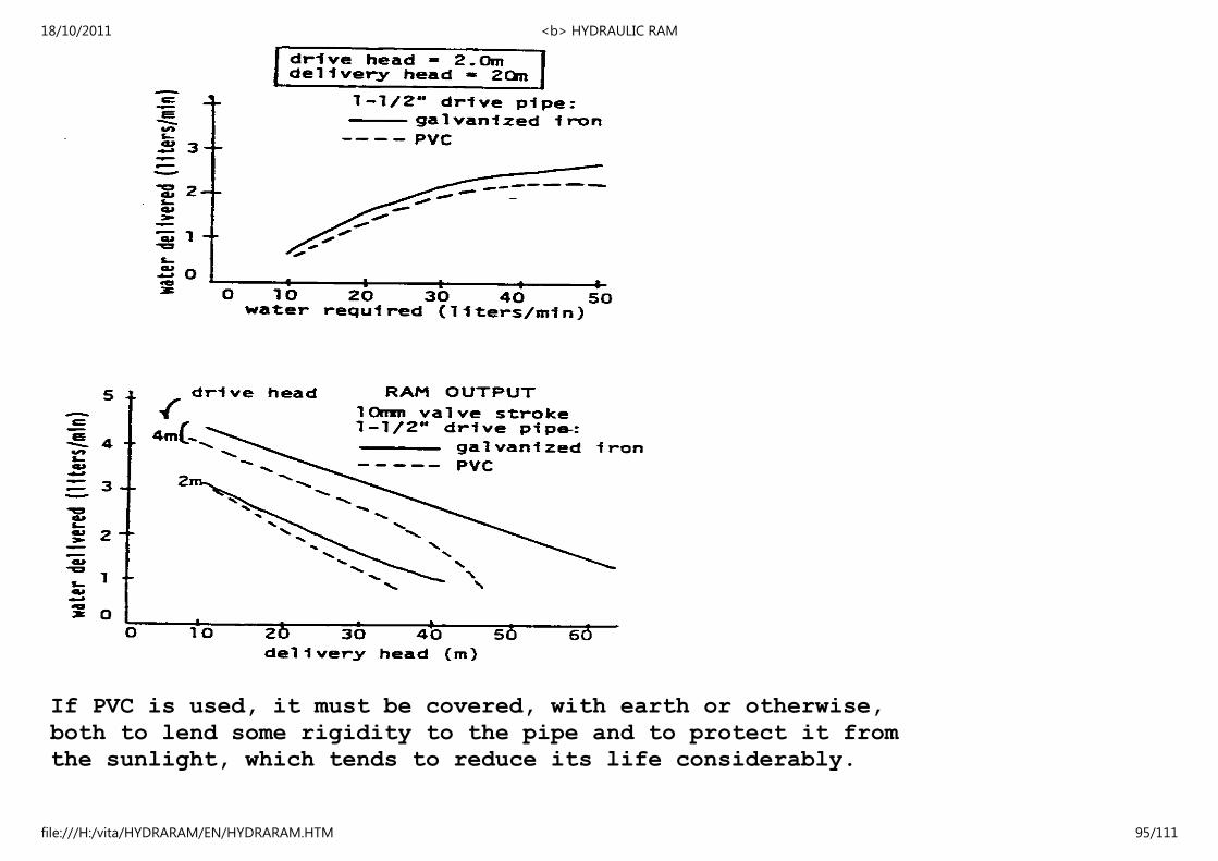
If PVC is used, it must be covered, with earth or otherwise,
both to lend some rigidity to the pipe and to protect it from
the sunlight, which tends to reduce its life considerably.
18/10/2011 <b> HYDRAULIC RAM
file:///H:/vita/HYDRARAM/EN/HYDRARAM.HTM 95/111

NOTES
Spring Loading the Waste Valve
If the ram is to be used for drive
heads over 4 meters, operating
ating frequencies become high and
the rate at which water is delivered
consequently decreases. To increase
this rate, a square ground
square ground compression spring
can be inserted as shown. This
spring should be made of stainless
steelorotherrust-free alloy.
This spring will keep the
valve open longer, increase the
quantity of water used by the pump,
and increase, to a point, the quantity
of water delivered. If it is
desired to increase the tension,
washers need simply be used as illustrated
in the second drawing at
the right.
The spring should have a spring
constant of about 10 newtons/cm
or 5 pounds/inch. Such springs
can be custom-made at low cost by
spring-makers if the spring constant,
18/10/2011 <b> HYDRAULIC RAM
file:///H:/vita/HYDRARAM/EN/HYDRARAM.HTM 96/111

the length, and the diameter
of the spring are specified.
<FIGURE 61>
06p46.gif (540x540)
18/10/2011 <b> HYDRAULIC RAM
file:///H:/vita/HYDRARAM/EN/HYDRARAM.HTM 97/111
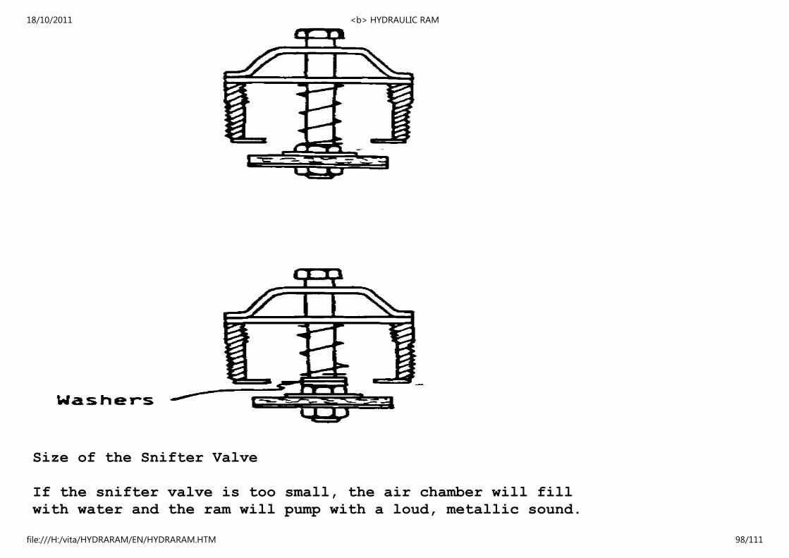
Size of the Snifter Valve
If the snifter valve is too small, the air chamber will fill
with water and the ram will pump with a loud, metallic sound.
18/10/2011 <b> HYDRAULIC RAM
file:///H:/vita/HYDRARAM/EN/HYDRARAM.HTM 98/111

If this should happen, either drill the hole of the snifter
valve slightly larger or use a nail or cotter pin with a
slightly smaller diameter.
If the snifter valve hole is too large, the ram will operate
less efficiently.
APPENDIX II
CONVERSION TABLES
Units of Length
1 Mile = 1760 Yards = 5280 Feet
1 Kilometer = 1000 Meters = 0.6214 Mile
1 Mile = 1.607 Kilometers
1 Foot = 0.3048 Meter
1 Meter = 3.2808 Feet = 39.37 Inches
1 Inch = 2.54 Centimeters
1 Centimeter = 0.3937 Inch
Units of Area
1 Square Mile = 640 Acres = 2.5899 Sq. Kilometers
18/10/2011 <b> HYDRAULIC RAM
file:///H:/vita/HYDRARAM/EN/HYDRARAM.HTM 99/111
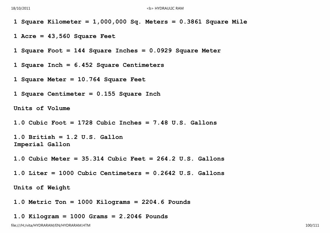
1 Square Kilometer = 1,000,000 Sq. Meters = 0.3861 Square Mile
1 Acre = 43,560 Square Feet
1 Square Foot = 144 Square Inches = 0.0929 Square Meter
1 Square Inch = 6.452 Square Centimeters
1 Square Meter = 10.764 Square Feet
1 Square Centimeter = 0.155 Square Inch
Units of Volume
1.0 Cubic Foot = 1728 Cubic Inches = 7.48 U.S. Gallons
1.0 British = 1.2 U.S. Gallon
Imperial Gallon
1.0 Cubic Meter = 35.314 Cubic Feet = 264.2 U.S. Gallons
1.0 Liter = 1000 Cubic Centimeters = 0.2642 U.S. Gallons
Units of Weight
1.0 Metric Ton = 1000 Kilograms = 2204.6 Pounds
1.0 Kilogram = 1000 Grams = 2.2046 Pounds
18/10/2011 <b> HYDRAULIC RAM
file:///H:/vita/HYDRARAM/EN/HYDRARAM.HTM 100/111

1.0 Short Ton = 2000 Pounds = 2.2046 Pounds
Units of Pressure
1.0 Poundsper square inch(*) = 144 Pounds per square foot
1.0 Pounds per square inch(*) = 27.7 Inches of Water(*)
1.0 Pounds per square inch(*) = 2.31 Feet of Water(*)
1.0 Pounds per square inch(*) = 2.042 Inches of Mercury(*)
1.0 Atmosphere = 14.7 Pounds per squareinch
(PSI)
1.0 Atmosphere = 33.95 Feet of Water(*)
1.0 Foot of Water = 0.433 PSI = 62.355 Pounds per square foot
1.0 Kilogram per square centimeter = 14.223 Pounds per square inch
1.0 Pounds per square inch(*) = 0.0703 kilogram per square
centimeter
(*) at 62 F or 16.6 C
Units of Power
18/10/2011 <b> HYDRAULIC RAM
file:///H:/vita/HYDRARAM/EN/HYDRARAM.HTM 101/111
1.0 Horsepower (English) = 746 Watt = 0.746 Kilowatt (kw)
1.0 Horsepower (English) = 550 Foot pounds per second
1.0 Horsepower (English) = 33,000 Foot pounds per minute
1.0 Kilowatt (KW) = 1000 Watt = 1.34 Horsepower (HP) English
1.0 Horsepower (English) = 1.0139 Metric Horsepower
(cheval-vapeur)
1.0 Metric Horsepower = 75 Meter X Kilogram/second
1.0 Metric Horsepower = 0.736 Kilowatt = 736 Watt
APPENDIX III
DECISION-MAKING WORK SHEET
If you are using this as a guideline for using the Hydraulic Ram
in a development effort, collect as much information as possible
and if you need assistance with the project, write VITA. A
report on your experiences and the uses of this handbook will
help VITA both improve the book and aid other similar efforts.
Publications Service
18/10/2011 <b> HYDRAULIC RAM
file:///H:/vita/HYDRARAM/EN/HYDRARAM.HTM 102/111

Volunteers in Technical Assistance
1600 Wilson Boulevard, Suite 500
Arlington, Virginia 22209 USA
CURRENT USE AND AVAILABILITY
o Describe current agricultural and domestic practices that
rely on water at some point.
o What water sources are available? Note whether sources are
small but fast-flowing, large but slow-flowing, etc.
o Are there dams already built in the area? If so, what has
been the effect of the damming? Note particularly are
evidence having to do with the amount of sediment carried
by the water-too much sediment can create a swamp.
o If water resources are not now harnessed, what seem to be
the limiting factors? Does the cost of the effort seem
prohibitive? Does the lack of knowledge of water power
potential limit its use?
NEEDS AND RESOURCES
o How is the problem identified? Who seems it as a problem?
o Has any local person expressed the need for a water
lifting or pumping technology? If so, can someone be
found to help the technology introduction process? Are
18/10/2011 <b> HYDRAULIC RAM
file:///H:/vita/HYDRARAM/EN/HYDRARAM.HTM 103/111

there local officials who could be involved and tapped
as resources?
o How will you get the community involved with the decision
of which technology is appropriate for them?
o Based on current agricultural and domestic practices, what
seem to be the areas of greatest need? Is irrigation water
needed some distance from thte water supply? Are stock
watering tanks or ponds required?
o Are tools and materials for constructing the ram and its
associated equipment available locally? Are local skills
sufficient? Some applications demand a rather high degree
of construction skill, although less maintenance skill is
required.
o Is there a possibility of providing a basis for small
business enterprise?
o What kinds of skills are available locally to assist with
construction and maintenance? How much skill is necessary
for construction and maintnenace? Do you need to train
people? Can you meet the following needs?
o Some aspects of the project require someone with
experience in surveying.
o Estimated labor time for full-time workers is:
18/10/2011 <b> HYDRAULIC RAM
file:///H:/vita/HYDRARAM/EN/HYDRARAM.HTM 104/111

- 8 hours skilled labor
- 40 hours unskilled labor
o If this is a part-time project, adjust the times
accordingly.
o Do a cost estimate of labor, parts, and materials needed.
o How will the project be financed?
o What is your schedule? Are you aware of holidays and
planting or harvesting seasons that may affect timing?
o How will you spread information on and promote use of the
technology?
IDENTIFY THE APPROPRIATE TECHNOLOGY
o Is more than one water supply technology applicable?
Weight the costs of various technologies--relative to each
other--fully, in terms of labor, skill required, materials,
installation, and operation costs. While one technology
may appear to be much more expensive in the beginning, it
could work, out to be less expensive after all costs are
weighed.
o Are there choices to be made between, say, a ram and a
windmill? Again, weigh all the costs: feasibility, economics
18/10/2011 <b> HYDRAULIC RAM
file:///H:/vita/HYDRARAM/EN/HYDRARAM.HTM 105/111

of tools and labor, operation and maintenance, social
and cultural dilemmas.
o Are there local skilled resources to guide the introduction
of this technology? Dam building, and irrigation equipment,
for example, should be considered carefully before
beginning work.
o Could a technology such as the hydraulic ram be usefully
manufactured and distributed locally?
o What changes would the proposed technology make on the
economic, social, and cultural structure of the area?
o Are there environmental consequences to the use of this
technology? What are they?
FINAL DECISION
o How was the final decision reached to go ahead with this
technology? Or, why was it decided against?
APPENDIX IV
RECORD-KEEPING WORK SHEET
CONSTRUCTION
Photographs of the construction process, as well as the finished
18/10/2011 <b> HYDRAULIC RAM
file:///H:/vita/HYDRARAM/EN/HYDRARAM.HTM 106/111
result, are helpful. They add interest and detail that might be
overlooked in the narrative.
A report on the construction process will include much very
specific information. This kind of detail can often be monitored
most easily in charts (see below). Some other things to
record include:
o Specification of materials used in construction.
o Adaptations or changes made in design to fit local
conditions.
o Equipment costs.
o Time spent in consturction--include volunteer time as well
as paid labor; full- or part-time.
o Problems--labor shortage, work shortage, training difficulties,
materials shortage, terrain, transport, vandalism.
Labor Account
Hours Worked
Name Job M T W T F S S Total Rate? Pay?
1
18/10/2011 <b> HYDRAULIC RAM
file:///H:/vita/HYDRARAM/EN/HYDRARAM.HTM 107/111

2
3
4
5
Totals
Materials Account
Item Cost Reason Replaced Date Comments
1
2
3
4
5
Totals (by week or month)
MAINTENANCE
Maintenance records enable keeping track of where breakdowns
18/10/2011 <b> HYDRAULIC RAM
file:///H:/vita/HYDRARAM/EN/HYDRARAM.HTM 108/111

occur most frequently and may suggest areas for improvement or
strengthening weakness in the design. Furthermore, these records
will give a good idea of how well the project is working out by
accurately recording how much of the time it's working and how
often it breaks down. Routine maintenance records should be kept
for a minimum of six months to one year after the project goes
into operation.
Labor Account
Also down time
Name Hours & Date Repair Done Rate? Pay?
1
2
3
4
5
Totals (by week or month)
Materials Account
Item Cost Per Item # Items Total Costs
1
18/10/2011 <b> HYDRAULIC RAM
file:///H:/vita/HYDRARAM/EN/HYDRARAM.HTM 109/111

2
3
4
5
Total Costs
OPERATION
Keep log of operations for at least the first six weeks, then
periodically for several days every few months. This log will
vary with the technology, but should include full requirements,
outputs, duration of operation, training of operators, etc.
Include special problems that may come up--a damper that won't
close, gear that won't catch, procedures that don't seem to make
sense to workers.
SPECIAL COSTS
This category includes damage caused by weather, natural
disasters, vandalism, etc. Pattern the records after the routine
maintenance records. Describe for each separate incident:
o Cause and extent of damage.
o Labor costs of repair (like maintenance account).
o Material costs of repair (like maintenance account).
18/10/2011 <b> HYDRAULIC RAM
file:///H:/vita/HYDRARAM/EN/HYDRARAM.HTM 110/111

o Measures taken to prevent recurrence.
========================================
========================================
18/10/2011 <b> HYDRAULIC RAM
file:///H:/vita/HYDRARAM/EN/HYDRARAM.HTM 111/111