HYDRAULIC PUMPS CYLINDERS JACKS PULLERS TOOLS · Basic double-acting system with an...
156
Professional Grade High Pressure Hydraulic Products, Systems and Tools PT0910-MSL04 (A) Catalog HYDRAULIC PUMPS CYLINDERS JACKS PULLERS TOOLS
Transcript of HYDRAULIC PUMPS CYLINDERS JACKS PULLERS TOOLS · Basic double-acting system with an...

Professional Grade High PressureHydraulic Products, Systems and Tools
PT0910-MSL04 (A) Catalog
HYDRAULIC PUMPS CYLINDERS JACKS PULLERS TOOLS

Power Team. Over 85 years experience in supplying Professional Gradehigh-pressure Hydraulic Pumps, Cylinders, Jacks, Pullers & Tools.
A Heritage of InnovationSince 1924, we’ve been instrumental in the development of innovativehigh force hydraulic power products, systems and tools. And many ofour products are known as the industry standard for rugged construction,reliability, and long service life. Today, we provide a full range ofprofessional grade products and services around the globe.
Power Team QualityPower Team Products are built tough with strict ISO 9000 manufacturingprocesses and are covered by a Lifetime Marathon Warranty*.
Global Distribution and ServiceWherever your job is in the world, the Power Team network of distributorsand service centers assures local product, parts and service availability.
*See Warranty page for coverage details.
Every effort has been made to assure the accuracy of product descriptions in this catalog at the time of printing. SPX Hydraulic Technologies reserves the right to modify or discontinue productswithout prior notice.
ABOUT POWER TEAMTough Products forTough Applications
Hydraulic Pumps• Predator Portable
Electric and Air Powered• Electric, Air, and Gas Powered• Hand Pumps• Valves, hoses and accessories
Hydraulic Cylinders• Rams• Standard• Construction• Industrial• High Tonnage• Pancake• Aluminum• Pulling
Jacks• Lifting Jacks• Inflatable Jacks• Post-Tensioning Jacks
Tools• Predator Torque Wrenches• Hydraulic Presses• Flange Spreaders• Nut Splitters• Gear Pushers/Pullers• Bearing Maintenance
Pushers/Pullers
Shop Equipment• Shop Presses• Floor Cranes• Load Rotors

CYLINDERS9-26
PUMPS36-69
SHOPEQUIPMENT
81-89
BEARINGMAINTENANCE
122-149
HYDRAULICACCESSORIES
71-80
JACKS90-101
IN-LINE VALVES…78-79
VALVES
PUMP MOUNTEDVALVES…32-35
PLC SERIESPancake Locknut Cylinders
26
SEAL KITS152-153
PH303C30 Ton Puller
134
102-119HYDRAULIC TOOLS
120-121MECHANICAL TOOLS
PLC SYNCHRONOUSLIFT AND LOWERING
SYSTEM...150
www.powerteam.com 3

BB1600, BB1601 ...... 116BC212 - BC212EUR ... 51BP12INT ..................... 51C51C - C10010C......... 11C55CBT - C2514CBT..................................... 14CB30 - CB100............. 17CBS55 - CBS200 ........ 98CBS60 ........................ 97CC5 - CC25 .............. 117DB10M - DB17M ..... 130DB17 - DB17H ......... 140DB30H....................... 141DG100, DG100B......... 75FC2200 - FC4400........ 87FK59 - FK159B........... 38HB443, HB444............ 56HFS3A - HFS6A ....... 113HNS150 - HNS225 ... 112HP35SP ..................... 114HS2000 - HS3000 ..... 115HST11........................ 135HST11S ..................... 134HT50A - HT200 ........ 118HTS50 ....................... 120IJ13 - IJ7320.............. 100IM10E, IM10H............ 94IPS10M, IPS17M ...... 130IPS17 - IPS17H ......... 140IPS30H ...................... 141IPS3017 - IPS3017B.. 142IPS5017 - IPS5017B.. 143IPS50H ...................... 141IPS5317 ..................... 144J24T - J259T............... ..93JAM10033 - JEM15026JM25 - JM430.............. 99K82, K83 ................... 135MB5 - MB16 ............. 145P12 - P59F ............. 36-37P19, P59....................... 37P157 - P460D .............. 38PA6 - PA6DM-2...... 40-41PA9, PA9H...................39PA50 - PA50RM.......... 42PA60, PA64 ................. 43PA172 - PA554....... 44-45PB1230C - PB51156C.................................... 145PC200, PC200RC........ 69PCHA Series.............. 110PD313 - PD812 ......... 114PE102 -PE104 ......................... 50PE172 - PE174M......... 52PE182 - PE184C ......... 53PE213 - PE214S.......... 54PE302 -PE304R-2.................... 55PE30TWP................... 108PE462 - PE464S........... 57
4
SPE556 - SPE5513DS.......................................... 85SPE10010 - SPE10013DS..................................... 86SPE10010R ................. 86SPE15013DSSPE20013DS............. 86SPH1010...................... 83SPM1010..................... 83SPM256....................... 84SPM256C .................... 82SPM2514..................... 84SPM556, SPM5513..... 85SPM10010................... 86SS2............................. 132TWSD1 - TWSD25... 104TWD1-063- TWD25-275.......... 105TWS Series................ 105TWH15 - TWH50...... 108TWP55....................... 109TWLC Series...... 106-1071020 - 1042 ............... 1271057 - 1060 ............... 1361062 ........................... 1381064, 1066.................. 1371070 ........................... 1391074 ........................... 1371076 ........................... 1391080 ........................... 13710461 ......................... ..661100 - 1111 ................ 1281121 - 1130................. 1291150 - 1154................. 1291155 - 1158................ 1331165, 1166 ................. 1291170, 1171 ................. 1331172 - 1178......... 132-1331188 ........................... 1351266 ........................... 12115235 ......................... 10116339 ......................... ..6817627 ........................... 66201454, 201923 ........... 20202178 - 202180.......... 12202777, 202778............ 66202817 ....................... 120203225 .........................66203264 ....................... 119204666 ....................... 120204928 ....................... 121204990 ....................... 119206767 ......................... 68207762 ......................... 68208380 - 208382........... 13208627 ....................... 132209199, 209200 ......... 121209593 ......................... 66213895, 213896 ........... 69216209 ......................... 6621669 - 21873 .............. 20
350637 ....................... 146350723 - 350724.......... 12350822, 350823.......... 113350895 - 350898.......... 13350984 ......................... 15351075 ......................... 14351106 ......................... 14351324, 351325............ 21351334 ......................... 21351574 ......................... 11351575 - 351576.......... 13351927 - 351931.......... 97351953, 351954 ........... 97351985 ....................... 11237045 ........................... 7538855, 38904............... 1838908, 38909 ............... 1339811 ......................... 12041331 ......................... 132420059 - 420064.......... 12420866 - 420871.... 22, 25421056, 421057........... 1444148, 44195 ............. 13244745, 44766 ............. 14745329 ......................... 12045589 ........................... 1747997 ......................... 13658943 - 58945 ............. 9860846 ........................... 8266053 - 66055.............. 97679, 680...................... 1297103 ........................... 1207136 ........................... 1337162 - 7168................ 1217307 - 7309................ 1217312 ........................... 1207395 ........................... 1207400, 7401 ................. 1217402 ........................... 1207420, 7421 ................. 1218000 - 8076 ................ 131885 ............................. 121927 - 939 .................... 1289002A - 9050A............. 919040 - 9089 ................. 759006X - 9015X............ 929105A .......................... 929112A - 9130A ............ 919015B - 9110B ............ 919205A - 9220A............ 929190 ............................. 809500, 9501................... 339502 ............................. 329506, 9507................... 339510 ............................. 679512, 9513................... 359515 ............................. 679516 .............................359517 ............................. 329519 ............................. 359520 ............................. 32
9521 ............................. 679552 ............................. 349560 ............................. 519561 - 9563.................. 509569, 9570, 9572.......... 349575 ............................. 799579 ............................. 349580, 9581.................... 799582, 9584.................... 329592 ............................. 349594 ............................. 349596, 9597.................... 789599, 9605.................... 359608 ............................. 789616 ............................. 779617 ............................. 769620 ............................. 679623 ............................. 799625 ............................. 679626, 9627.................... 769631 ............................. 799633 ............................. 799634, 9635.................... 769636 - 9640................... 779641 ............................. 679642 ............................. 769643 ............................. 679644 ............................. 769645 - 9647................... 779648 ............................. 769670 - 9690................... 809691 ............................. 769692 - 9705 .................. 809720, 9721.................... 789733 - 9783................... 729758, 9763 ................... 959765 - 9775................... 729785 - 9788.................1 199792 - 9800 .................. 73
NUMERIC INDEX22185 ......................... 13222274, 22275................ 2024196, 24197................ 2024813, 24814................ 2025017 ........................... 66250175 ......................... 68250341 - 250343.........1 01250353 ....................... 101250459 ....................... 114250682 ....................... 101251002 ....................... 146251468 ....................... 146251646, 251647 ......... 145251660 ......................... 66252511, 252512 ........... 68252542 - 253391.......... 9525388 - 25750 ........ 12-1325931 ........................... 2027198 ........................... 2027241 ......................... 13227315 ......................... 13228230 ........................... 2028250 - 28256............ 13228323GY8 ................. 13228612 - 28644 ............. 1829595 ........................... 20302482, 302483........... 20303045 ....................... 147303785 ......................... 20304718 ......................... 66307159 ....................... 101307281 ....................... 119308022 ....................... 112308435OR9 Thru308440OR9 ........ 140-144308840 ....................... 112309652, 309653............ 6631772, 31776........... 12-1332054 ......................... 13232118 ........................... 2032325...................... 12-1332698 - 33439 ............. 203344A ........................ 12033856 - 33865............ 13234136 ........................... 2034251 ........................... 1834331 ......................... 13234510, 34511 ............... 2034758 ........................... 2034698 ......................... 13234755, 34756 ............... 20350090 ....................... 101350094 - 350100.......... 12350144, 350145 ........... 11350184 ......................... 12350207 - 350209......... 101350320 - 350332.......... 17350376 .................... 11,15350431 ......................... 68350549, 350550.......... 113350593 - 350594........ 146
PE552 - PE554T........... 59PE554W........................ 59PE4004, PE4004S ....... 62PG120HM ................... 65PG303 - PG554 ........... 63PG1200M-4 - PG1204S...................................... 65PG4004, PG4004S ...... 65PH53C, PH53CR....... 136PH63C - PH113C ...... 134PH103C, PH103CR... 136PH172 - PH503 ......... 137PH303C ..................... 134PH553C - PH553CL13................................... 146PH1002 - PH1002J.... 147PLA6014 -PLE6014K.............. 96-97PMA, PUA............. 46-49PMA355 - PME355S... 99PMA55 - PME55S...... 99PLC672 - PLC5652..... 26PPH17 - PPH50R ........................................ 138-139PQ603 - PQ1204S ........................................... 60-61PR102 - PR104.......50-51PR2100J Thru PR3100S.............................. 148-149R552C - R56510C....... 22R1002D - R56510D .... 23R552L - R56510L ....... 25RA202 - RA1006 ........ 15RA556L, RA1006L..... 24RB8013S - RB20013S .................................... 88-89RC5.............................. 69RC12V......................... 51RD106 - RD50013 ...... 21RH102 - RH2008 ... 18-19RH306D....................... 19RHA306....................... 18RHA604D.................... 19RH121T....................... 18RLS50 - RLS1500S..... 16RP20 - RP104.............. 69RP25, RP55 ................. 14RSS101 - RSS2503 ..... 17RT172 - RT1004.......... 20RV21278 - RV21278-90....................................... 79RWP55....................... 111SF50....................... 85, 88SF150..................... 86, 88SJ2010 - SJ3010P........ 95SP1010A...................... 83SPA256, SPA2514....... 84SPA556........................ 85SPE1010, SPE1010D .. 83SPE256 - SPE2514DS........................................... 84

Hydraulic Couplers...................... 73Hydraulic Cranes ........................ 87Hydraulic Cylinders ................ 9-26Hydraulic Fittings ....................... 80Hydraulic Gauges .................. 74-75Hydraulic Hose ........................... 72Hydraulic Jacks ..................... 91-93Hydraulic Oil .............................. 77Hydraulic Presses, Shop .............................. 81-86, 88-89Hyd. Puller Sets ................ 140-144Hydraulic Pumps .................. 36-65Hydraulic Punches ................... 114Hydraulic Spreaders.......... 113, 115Hydraulic System Testers.. 118-119Hydraulic Tester Accessories.... 119Hydraulic Tools ................ 103-119Hydraulic Valves Pump Mounted ............ 32-35, 70 In-Line ...............................78-79
IIndustrial Maintenance Sets........ 94Industrial Maintenance Puller Sets..... 130, 140-144In-Line Valves ...................... 78-79Inflatable Jacks .................. 100-101Intensifier, Hydraulic ................. 56Internal Pulling Attachments........................... 129
JJack Modules......................... 98-99Jacks, High-Tonnage ...... 22-23, 25Jacks, Hydraulic .................... 91-93Jacks, Hydraulic Toe................... 93Jacks, Inflatable ................. 100-101Jacks, Stressing .......................... 95Jimmy Bars .............................. 121
LLightweight Handpump ............. 37Load-Lowering Valve ................ 78Low Profile Cylinders ................ 16Low Clearance Torque Wrenches ....... 106-107
MMagnetic Pick-Up Tool............. 120Magnetic Strip............................. 68Maintenance Sets ....................... 94Manifolds ................................... 76Metering Valve ..................... 78-79Mini Jack .................................... 92
NNut Splitters ............................. 112
OOil, Hydraulic ............................. 77“O” Ring Seal Pick .................. 120
PPancake Cylinders....................... 26Photo Tachometer, Digital ....... 120PLC Synchronous Lift.............. 150Pipe Flange Spreaders .............. 113Presses, HydraulicRoll-Bed ................................ 88-89Presses, Hydraulic Shop .............................. 81-86. 88-89Pressure Gauges, Hydraulic .. 74-75Pressure Switches ....................... 67Protective Blankets ................... 145Pry Bars..................................... 121
Puller Adapters........................... 131Puller Attachments..................... 129Puller, Blind Hole ..................... 132Pullers, Bearing... 127-144. 146-149Pullers, Bearing Cup.................. 129Pullers, Gear ....... 127-144, 146-147Pullers, Hydraulic ....................... 134-144, 146-149Pullers, Internal.......................... 129Pullers, Jaw-Type .......... 127, 134, 136-137, 146-147Pullers, Pulley ........................... 129Pullers, Sets ................ 130, 140-144Pullers, Slide Hammer........ 132-133Pulley Pullers............................. 129Pull Cylinders ............................. 14Pump Accessories, Hydraulic ...................... 66-69Pump Cart ................................... 69Pump Mounted Valves .......... 32-35Pump Reservoirs.......................... 69Pumps, Hydraulic ..................36-65Pumps, Hydraulic, Air............39-45Pumps, Hydraulic, Electric ....50-62Pumps, Hydraulic, Gasoline...63-65Pumps, Hydraulic, Hand ....... 36-38Punches, Hydraulic....................114Push-Pullers, Hydraulic......138-139Push-Pullers, Mechanical...........128
QQuality Standards, Industry ...... 154Quarter Horse Pumps .............50-51“Quiet” Pumps........................60-61
RRailroad Axle Journal BearingService Equipment............. 148-149Ratcheting Chain Wrenches.......121Remote Controls .........................66Reservoir Breather Kit.................68Rethreading Tools .................... 120Roll-Bed® Presses ................. 88-89
SSeal Kits............................. 152-153Shaft Protectors..........................131Shop Presses ...............81-86, 88-89Shorty Cylinders ......................... 17Slide Hammer Pullers.........132-133Solenoid-Operated Valves ................................ 34-35Spanner Wrenches .................... 121Spreaders, Hydraulic .........113, 115Square Drive Torque Wrenches.......... 104-105Standards, Quality..................... 154Step Plate Adapters................... .131Storage Boxes,Puller Sets ................................. 145Straightening Fixtures ..... 85-86, 88Straightening Tool .................... 135Stressing Jacks and Pumps................. 58-59, 95Subplates, Pump ......................... 67Switches, Hand and Foot............. 66Synchronous Lift....................... 150
TTesters, Hydraulic System..118-119Temperature & Fluid Level Gauge................. 68Thread Chaser............................120Threaded Adapters, Puller ........ 131
Tire Removing Tool...................116Toe Jacks, Hydraulic....................93Tools, Hydraulic ................102-119Torque Wrench Pumps ...... 108-111Torque Wrench ................. 104-107Torque Wrench Links............... 107Torque Wrench Sockets ........... 105Torque Wrench,Low Clearance .................. 106-107Torque Wrench Reducers.......... 107Twin Hose.................................. 108
VV-Belt Pulley PullingAttachments ..............................129Valves, Hydraulic Pump Mounted ........ 32-35, 70 In-Line........................... 78-79Viton Seal Kits ............ 68, 152-153
WWarranty.................................... 155Wrenches, Industrial ................. 121Wrenches, Ratcheting Chain..... 121Wrenches, Spanner ................... 121Wrenches, Torque ............. 104-107
www.powerteam.com 5
AAdapters, Step Plate................... 131Adapters, Threaded(Puller) ...................................... 131Air/Hydraulic Pumps............. 39-45Aluminum Cylinders ............ 15, 24Attachments, Pulling ................ 129Axle Journal Roller BearingService Equipment............. 148-149
BBead Breaker............................. 116Bearing Cup Remover .............. 133Bearing Installer................. 148-149Bearing PullingAttachments .............................. 129Bench Presses ............................. 83Blankets, Protective .................. 145Blind Hole Puller Set ................ 132
CCasters ....................................... 145Center-Hole Cylinders........................... 18-19 Accessories ............................ 18C-Clamps ................................... 117Center-Hole Twin Cylinders........ 20C-Frame Press.............................. 82Chain Wrenches ........................ 121Chaser, Thread .......................... 120Counter-balance Valve ............... 78Couplers, Hydraulic..................... 73Cranes, Mobile............................ 87Cribbing Block Sets.............. 17, 98Cylinders, Hydraulic ............... 9-26Cylinders Pancake ...................... 26
DDigital Pressure Gauge.......... 74-75Double-Acting Cylinders ..................................... 19, 21, 23
EElectric/Hydraulic Pumps................... 50-55, 57-62“Enforcer 55” Hydraulic Puller .................. 146“Enforcer 100” Hydraulic Puller .................. 147
FFixtures, Straightening ... 85, 86, 88Flange Spreaders....................... 113Floor Cranes, Mobile.................. 87Flow Characteristics, Valves .......................................... 78-79Fluid Level &Temperature Gauge..................... 68Foot Pump Conversion Kit......... 38Forcing Presses .......... 81-86, 88-89
GGauges, HydraulicPressure................................... 74-75Gear and PulleyPullers ................ 127-144, 146-147Gland Nut Wrench, Adjustable. 121
HHead Inserts, Cylinder ................ 18High PressureAir Operated Pump ............... 46-49Hose, Hydraulic .......................... 72Hydra Grip-O-Matic Pullers..... 134Hydraulic Accessories .......... 71-80
ALPHABETICAL INDEX
6
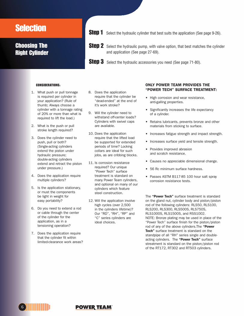
Step 1 Select the hydraulic cylinder that best suits the application (See page 9-26).
Step 2 Select the hydraulic pump, with valve option, that best matches the cylinderand application (See page 27-69).
Step 3 Select the hydraulic accessories you need (See page 71-80).
ONLY POWER TEAM PROVIDES THE“POWER TECH” SURFACE TREATMENT:
• High corrosion and wear resistance,anti-galling properties.
• Significantly increases the life expectancy of a cylinder.
• Retains lubricants, prevents bronze and other materials from sticking to surface.
• Increases fatigue strength and impact strength.
• Increases surface yield and tensile strength.
• Provides improved abrasion and scratch resistance.
• Causes no appreciable dimensional change.
• 56 Rc minimum surface hardness.
• Passes ASTM B117-85 100 hour salt spray corrosion resistance tests.
The “Power Tech” surface treatment is standardon the gland nut, cylinder body and piston/pistonrod of the following cylinders: RLS50, RLS100,RLS200, RLS300, RLS500S, RLS750S,RLS1000S, RLS1500S, and RSS1002. NOTE: Bronze plating may be used in place of the“Power Tech” surface finish for the piston/pistonrod of any of the above cylinders.The “PowerTech” surface treatment is standard on the standpipe of all “RH” series single and double-acting cylinders. The “Power Tech” surfacestreatment is standard on the piston/piston rodof the RT172, RT302 and RT503 cylinders.
1. What push or pull tonnage is required per cylinder in your application? (Rule of thumb; Always choose a cylinder with a tonnage rating of 20% or more than what is required to lift the load.)
2. What is the push or pull stroke length required?
3. Does the cylinder need to push, pull or both? (Single-acting cylinders extend the piston under hydraulic pressure; double-acting cylinders extend and retract the piston under pressure.)
4. Does the application require multiple cylinders?
5. Is the application stationary,or must the components be light in weight for easy portability?
6. Do you need to extend a rod or cable through the center of the cylinder for the application, as in a tensioning operation?
7. Does the application require that the cylinder fit within limited-clearance work areas?
8. Does the application require that the cylinder be “dead-ended” at the end of it’s work stroke?
9. Will the cylinder need to withstand off-center loads? Cylinders with swivel caps are available.
10. Does the application require that the lifted load be supported for extended periods of time? Locking collars are ideal for such jobs, as are cribbing blocks.
11. Is corrosion resistance required? Our unique “Power Tech” surface treatment is standard on many Power Team cylinders,and optional on many of our cylinders which feature steel construction.
12. Will the application involve high cycles (over 2,500 in the cylinders lifetime)? Our “RD”, “RH”, “RP” and “C” series cylinders are ideal choices.
Choosing The Right Cylinder
Selection
CONSIDERATIONS:

Torque & Puller
CHOOSING THE RIGHT
TORQUE WRENCH
The Questions you need to ask.Tool
CHOOSING THE RIGHT
PULLER
2.To determine oilcapacity of a cylinder:
3.To determine reservoircapacity needed for a multiple cylinder system:
WHAT TYPE OF CYLINDER DO YOU NEED?
Note: For double-acting cylinders, oil in rod end of cylinder must be subtracted to determine capacity.
1.To determine a cylinder’s force capacity:
FORCE
Stroke
Threads
Coupler
MountingBolts
3. Single acting or double acting tool?4. What size bolts need to be loosened or tightened? 5. What is torque requirement for the application?
7. What type of pump to power the tool – electric, air, hand?
1. Mechanical puller or hydraulic puller?(page 127-130 and page 134-147)
2. Does the job require a two jaw pulleror a three jaw puller?
3. How much force is needed to com-plete the pull?
4. How much reach is needed?5. How much spread is needed?
5.To determine pistontravel rate (cm/min)of a power-driven pump:
6.Time (min) taken to movecylinder piston to full stroke ofa power-driven pump:
4.To determine no. ofstrokes of a handpump: Cylinder Effective Area (cm2) x Stroke (cm)
Pump Displacement (cm3/stroke)
Pump Oil Flow (cm3/min)
Cylinder Effective Area (cm2)
Total Cylinder Displacement (cm3)
Pump Displacement (cm3/min)
FORCE (kg)
OILCAPACITY
(cm3)
USABLEOIL
=
=
=
CylinderEffective Area
(cm2)
CylinderEffective Area
(cm2)
Oil Cap. of Cyl.(cm3)
x
x
x
Pressure fromPump
(kg/cm2)
CylinderStroke(cm)
Number of Cyl. inSystem
Choosing the Right Tool
www.powerteam.com 7
1. Are there work area space/access issues or tool size limitations?2. How far from the stationary object will the reaction arm be placed?
(Reaction arm must rest against stationary object for support)
6. Based on torque value, how much pressure required? (pressure setting for pump)
ConversionVolume: 1 litre = 1000 cm3
1 U.S. gallon = 231 in3
Mass: 1 short tons = 2,000 lbs 1 metric tonne = 2204.6 lbs 1 metric tonne = 1000 kgPressure: 10,000 psi = 689 bar = 703 kg/cm2
Metric to Imperial ConversionLength: 1 mm = 0.0394 inArea: 1 cm2 = 0.1550 in2
Volume: 1 cm3 = 0.06102 in3
Volume: 1 litre = 0.2642 U.S. gallonMass: 1 kg (10N) = 2.2046 lbPower: 1 kW = 1.341 hpPressure: 1 kg/cm2 = 14.219 psiPressure: 1 bar = 14.5038 psiTorque: 1 Nm = 0.7376 ft.lb

8
1
2
9
2 4
11
12
10
1
8
5
4 5
118
10
Basic single-acting system with a hand pump, gauge,hose and single-acting cylinder.
Basic single-acting system with a hand pump, gauge,hose, multiple shut-off valves, load-lowering valves
and multiple cylinders.
Cylinder – applies hydraulic force.
Pump – a device for converting mechanical energy to fluid energy.
Directional valve – controls the directionof hydraulic fluid in the system.
Gauge – measures Bar pressure (or Psi-Pounds per Square Inch) and/or force.
Hose – transports hydraulic fluid.
Manifold – allows distribution of hydraulicfluid from one source to several cylinders. (No. 9617)
Swivel Connector – allows proper alignment of valves and/or gauges.Used when units being connected cannot be rotated. (No. 9675)
Quick Coupling – “hose half” and “cylinder half” couplings are usedfor quick connection and fluid flow checkwhen separated. (No. 9797 and 9798)
Shut-Off Valve – regulates the flow ofhydraulic fluid to or from cylinders. (No. 9642 or 9644)
Load-Lowering Valve – allows meteredlowering of cylinder and provides safetywhen prolonged load holding is required.(No. 9596)
Tee Gauge Adapter – allows for installation of pressure/tonnage gaugeanywhere in the hydraulic system. (No. 9670)
Pipe Plug – for blocking unused portswithin the system. (No. 9687)
12
11
10
9
8
7
6
5
4
3
2
1
HydraulicCIRCUITS
These are just a few basic systems possible with Power Teamhydraulic components. Countless applications are possible: In presses, for lifting or jacking applications or in production or maintenance setups. The pump shown is a typical handpump or electric/hydraulic unit. Air or gas driven/hydraulic pumps are available.
Pumps, Cylinders, Controls
Basic double-acting system with an electric/hydraulicpump,shut-off valves, load-lowering valves and multiple
double-acting cylinders.
2
5
18
10
5129
11
7
36

www.powerteam.com 9
CYLINDERSF R O M 2 T O 1 , 0 0 0 T O N S
SUPERIOR FEATURES OF POWER TEAM HYDRAULIC CYLINDERS:
We build our own cylinders in our ISO 9001 registered manufacturingfacility. All Power Team cylinders aredate-coded. Maximum pressure ratingand capacity are stamped on thecylinder. All cylinders comply to thedemanding ASME B30.1 standardand are proof tested to 125% ofcapacity before leaving our factory.
Cylinder bores are roller burnished to harden the surface and make itsmoother, increasing seal life by30%. Base mounting holes withstandfull capacity of the cylinder. Typicalcylinder burst pressures range from1700 to 2400 bar. Cylinders withgland nuts may be "dead-ended" at 700 bar. Cylinders are assembled
and tested by certified assemblers.Eddy current and mag particle inspection detects flaws in the steel.Cylinder bodies are solid steel,not welded like some competitivecylinders. Material is removed fromsurface, to assure that any flaws are removed.
Page
C SERIES…10-11General Purpose Cylinders
Page
CBT SERIES… 14Threaded End Cylinders
Page
RA SERIES…15Aluminum Cylinders
Page
RSS SERIES…17Shorty Cylinders
Page
RLS SERIES…16Low Profile Cylinders
Page
RH SERIES…18-19Center Hole Cylinders
Page
RT SERIES…20Center Hole Power-twin®Cylinders
Page
RP SERIES…14Pull Cylinders
Page
PLC SERIES…26Locking Collar, Pancake
Single Acting, Load-Return
Page
RD SERIES…21Double-Acting,
Hydraulic-Return
Page
RL SERIES…24-25Locking Collar
(Aluminum) Single-Acting/Spring-Return(Steel) Single-Acting, Load-Return
Page
R SERIES…22-23Single-Acting, Load Return
Double-Acting, Hydraulic Return

10
C106C
C756C
Base mounting holes
CY
LIN
DER
SGeneral PurposeCYLINDERS C SERIES
5-100 TONSGeneral Purpose, SingleActing, Spring-Return
Rugged, high quality cylinderused for lifting and pressing
CY
LIN
DER
S
Conforms toASME B30.1
Cylinder Cap
CollarThreads (withstands full load)
ChromePlatedPiston Rod
Stop Ring (withstands fulldead-end load)
Aluminum BronzeBearing
Tough Urethane Seal
Heavy-dutyReturn Springwith Max.Number of Coils
Rod Wiper
Internal PistonThreads
Steel orAluminumBronze Bearing
Easy Repair Access
• Aluminum bronze bearing reduces wear caused by off-center loads.
• Maximum sized springs speed piston return and increase spring life.
• Solid steel cylinder body for durability.• Chrome plated piston rod resists wear and corrosion.• Wide range of accessories available to thread onto
piston rod, collar, or onto cylinder base.• Base mounting holes standard on 5 through 55 ton
cylinders; optional on 75 and 100 ton cylinders.• A 3/8" NPTF female half coupler is standard.
BASE MOUNTING HOLES FOR “C”CYLINDERS
* Consult Factory (45° from coupler)† 90° from coupler.
Cylinder Tonnage No. Thread Thread Bolt CircleHoles Size Depth (mm) Diameter (mm)
5 1⁄4-20 9.5 25.410 5⁄16-18 39.715 3⁄8-16 47.625 58.755 95.3
*Optional 75 3⁄4-10 114.3*Optional 100 1-8 120.7
2†
4
1⁄2-13
12.7
19.1
25.4

www.powerteam.com 11
Base mounting holes: see page 10.
CylCapTons
10
01
05
15
25
55
75
A B C D E F H J K cirteM n PistonotsiP
Re- Ex- Collar Base Piston Rod Int. Rod Cylinder TonsOil tracted tended Outside Collar Thread to Rod Thread (in.) Protru- Bore Effective at
Stroke Order Cap. Height Height Dia. Thread Length Port Dia. and Depth sion Dia. Area 700 Weight(mm) No. (cm3) (mm) (mm) (mm) (in.) (mm) (mm) (mm) (mm) (mm) (mm) (cm2) (bar) (kg) 25,4 C51C 18 110,3 138,1 38,1 11/2-16 28,6 19,1 25,4 3/4-16 x 15,9 6,4 28,6 6,4 4,5 1,082,6 C53C 52 165,1 247,7 38,1 11/2-16 28,6 19,1 25,4 3/4-16 x 15,9 6,4 28,6 6,4 4,5 1,5133,4 C55C 85 215,9 349,3 38,1 11/2-16 28,6 19,1 25,4 3/4-16 x 15,9 6,4 28,6 6,4 4,5 1,8184,2 C57C 118 273,1 457,2 38,1 11/2-16 28,6 19,1 25,4 3/4-16 x 15,9 6,4 28,6 6,4 4,5 2,3235,0 C59C 151 323,9 558,8 38,1 11/2-16 28,6 19,1 25,4 3/4-16 x 15,9 6,4 28,6 6,4 4,5 2,625,4 C101C 36 92,1 117,5 57,2 21/4-14 28,6 19,1 38,1 1-8 x 19,1 6,4 42,8 14,4 10,2 1,854,0 C102C 79 120,7 174,6 57,2 21/4-14 28,6 19,1 38,1 1-8 x 19,1 6,4 42,8 14,4 10,2 2,3104,8 C104C 151 171,5 276,2 57,2 21/4-14 28,6 19,1 38,1 1-8 x 19,1 6,4 42,8 14,4 10,2 3,0155,6 C106C 225 247,7 403,2 57,2 21/4-14 28,6 19,1 38,1 1-8 x 19,1 6,4 42,8 14,4 10,2 4,3206,4 C108C 362 298,5 504,8 57,2 21/4-14 28,6 19,1 38,1 1-8 x 19,1 6,4 42,8 14,4 10,2 5,0257,2 C1010C 370 349,3 606,4 57,2 21/4-14 28,6 19,1 38,1 1-8 x 19,1 6,4 42,8 14,4 10,2 5,9308,0 C1012C 444 400,1 708 ,0 57,2 21/4-14 28,6 19,1 38,1 1-8 x 19,1 6,4 42,8 14,4 10,2 6,6358,8 C1014C 518 450,9 809,6 57,2 21/4-14 28,6 19,1 38,1 1-8 x 19,1 6,4 42,8 14,4 10,2 7,3406,4 C1016C 592 520,7 927,1 57,2 21/4-14 28,6 19,1 38,1 1-8 x 19,1 6,4 42,8 14,4 10,2 8,425,4 C151C 51 123,8 149,2 69,9 23/4-16 28,6 19,1 44,5 1-8 x 19,1 6,4 50,8 20,3 14,2 3,454,0 C152C 110 149,2 203,2 69,9 23/4-16 28,6 19,1 44,5 1-8 x 19,1 6,4 50,8 20,3 14,2 4,0104,8 C154C 211 200 ,0 304,8 69,9 23/4-16 28,6 19,1 44,5 1-8 x 19,1 6,4 50,8 20,3 14,2 5,2155,6 C156C 315 271,4 427,0 69,9 23/4-16 28,6 19,1 44,5 1-8 x 19,1 6,4 50,8 20,3 14,2 6,9206,4 C158C 418 322,2 528,6 69,9 23/4-16 28,6 19,1 44,5 1-8 x 19,1 6,4 50,8 20,3 14,2 8,1257,2 C1510C 521 373 ,0 630,2 69,9 23/4-16 28,6 19,1 44,5 1-8 x 19,1 6,4 50,8 20,3 14,2 9,4308,0 C1512C 625 423,8 731,8 69,9 23/4-16 28,6 19,1 44,5 1-8 x 19,1 6,4 50,8 20,3 14,2 10,5358,8 C1514C 728 474,6 833,4 69,9 23/4-16 28,6 19,1 44,5 1-8 x 19,1 6,4 50,8 20,3 14,2 11,8406,4 C1516C 824 522,3 928,7 69,9 23/4-16 28,6 19,1 44,5 1-8 x 19,1 6,4 50,8 20,3 14,2 12,825,4 C251C 84 139,7 165,1 85,7 35/16-12 49,2 25,4 57,2 11/2-16 x 25,4 9,5 65,1 33,2 23,4 5,450,8 C252C 169 165,1 215,9 85,7 35/16-12 49,2 25,4 57,2 11/2-16 x 25,4 9,5 65,1 33,2 23,4 6,3101,6 C254C 338 215,9 317,5 85,7 35/16-12 49,2 25,4 57,2 11/2-16 x 25,4 9,5 65,1 33,2 23,4 8,0158,8 C256C 528 273,1 431,8 85,7 35/16-12 49,2 25,4 57,2 11/2-16 x 25,4 9,5 65,1 33,2 23,4 9,8209,6 C258C 697 323,9 533,4 85,7 35/16-12 49,2 25,4 57,2 11/2-16 x 25,4 9,5 65,1 33,2 23,4 11,6260,4 C2510C 865 374,4 635,0 85,7 35/16-12 49,2 25,4 57,2 11/2-16 x 25,4 9,5 65,1 33,2 23,4 13,3311,2 C2512C 1.036 425,5 736,0 85,7 35/16-12 49,2 25,4 57,2 11/2-16 x 25,4 9,5 65,1 33,2 23,4 15,0362,0 C2514C 1.205 476,3 838,2 85,7 35/16-12 49,2 25,4 57,2 11/2-16 x 25,4 9,5 65,1 33,2 23,4 16,750,8 C552C 362 174,6 225,4 127,0 5-12 55,6 34,9 79,4 - 3,2 95,3 71,2 50,1 14,7108,0 C554C 769 231,8 339,7 127,0 5-12 55,6 34,9 79,4 - 3,2 95,3 71,2 50,1 18,7158,8 C556C 1.131 282,6 441,3 127,0 5-12 55,6 34,9 79,4 - 3,2 95,3 71,2 50,1 23,1260,4 C5510C 1.853 384,2 644,5 127,0 5-12 55,6 34,9 79,4 - 3,2 95,3 71,2 50,1 30,4336,6 C5513C 2.398 460,4 796,9 127,0 5-12 55,6 34,9 79,4 - 3,2 95,3 71,2 50,1 35,3155,6 C756C 1.596 314,3 469,9 146,1 53/4-12 44,5 31,8 95,3 - 3,2 114,3 102,6 72,1 33,3333,4 C7513C 3.421 492,1 825,5 146,1 53/4-12 44,5 31,8 95,3 - 3,2 114,3 102,6 72,1 49,650,8 C1002C 675 219,1 269,9 158,8 61/4-12 57,2 41,3 104,8 - 3,2 130,2 133,0 93,6 28,5168,3 C1006C 2.245 336,6 504,8 158,8 61/4-12 57,2 41,3 104,8 - 3,2 130,2 133,0 93,6 41,2260,4 C10010C 3.467 428,6 689,0 158,8 61/4-12 57,2 41,3 104,8 - 3,2 130,2 133,0 93,6 51,2
Swivel Cap(Optional)
Cylinder Part Tons No. A (mm) B (mm)
10 or 15 350144 22,4 30,1
25 350145 28,7 50,8
55 or 75 350376 31,8 71,4
100 351574 48,5 88,1

12
MountingaccessoriesC Series
Accessories
Plain AdapterThreaded Adapter
Cylinder Tons Part No. A (mm) B (mm) C (in) D (mm) E (mm) 5 25748 44,5 22,4 3/4-14 NSPM 4,8 12,7 10 25664 41,4 36,6 1 1/4-11 1/2 NSPM 7,9 14,2 25 25654 57,2 54,1 2-11 1/2 NSPM 9,7 16
Cylinder Tons Part No. A (mm) B (mm) C (mm) D (mm) E (mm) F (in) 5 350095 44,5 28,7 16 36,6 16 10 or 15* 350094 65 42,9 22,4 58,7 25,4 1-8 25** 420059 74,7 57,2 31,8 68,3 31,8 1
* Can be used with RD106, RD1010 Cylinder.** Can be used with RD256, RD2514 Cylinder.
Cylinder Tons Part No. A (mm) B (mm) C (mm) D (in) E (in)
)ni( 5 202178 (threaded) 41,4 28,7 26,9 3/4-14 NPT 3/4-16UNF-2A 10 or 15 202179 ( threaded) 46,0 26,9 41,4 1 1/4-11 1/2 NPT 1-8UNC-2A 25 202180 ( threaded) 69,9 47,8 60,5 2-11 1/2 NPT 1 1/2-16UN-2A 10 or 15 350724 (plain) 50,8 31,8 37,6 - 1-8UNC-2A 25 350723 (plain) 54,1 31,8 57,2 - 1 1/2-16UN-2A
Cylinder Tons Part No. A (mm) B (mm) C (mm) D (in) E (mm) 5 350099 76,2 25,4 54,1 1 1/2-16UN-2B 8,6 10 350100 88,9 25,4 66,8 2 1/4-14UNS-2B 8,6 15 350184 88,9 25,4 66,8 2 3/4-16UN-2B 8,6 25 420064 127 50,8 93 3 5/16-12UN-2B 16,8
Piston Clevis
Cylinder Order A (mm) B (mm) C (mm) 10 420062 177,8 127 11,2
25 420063 177,8 127 11,2
Threaded Connector
Support Base
Cylinder Mounting Plate
3/4-16
1/2-16CYL
IND
ERS
CYL
IND
ERS

www.powerteam.com 13
CYLIN
DER
SC
YLIND
ERS
Cylinder Tons Part No. A (mm) B (mm) C (mm) D (mm) E (mm) F (mm) 5 350096 52,3 28,7 16 16 14,2 6,4
10 350097 76,2 42,9 22,4 25,4 25,4 6,4
15 350098 77,7 42,9 22,4 25,4 25,4 6,4
25 420061 90,4 57,2 31,8 31,8 38,1 6,4
Cylinder Tons Part No. A (mm) B (mm) C (in) D (mm/in) F 5† 208380 41,4 44,5 3/4-14NPSM 7,1 Dia. (No.2) 1/4-20 UNC x 3/4”
Lg. Socket Head Cap Screws 10† 208381 47,8 63,5 1 1/4-11 1/2-NPSM 8,6 Dia. (No.2) 5/16-18 UNC x 3/4”
Lg. Socket Head Cap Screws 25† 208382 60,5 98,6 2-11 1/2-NPSM 13,5 Dia. (No.2) 1/2-13 UNC x 1”
Lg. Socket Head Cap Screws
Cylinder Tons Part No. A (mm) B (mm) C (in) D (mm) 5 25750* 114,3 63,5 3/4-14-NPSM 34 10 32325* 166,6 88,9 1 1/4-11 1/2-NPSM 36,6
Cylinder Part Tons No. A (mm) B (mm) C (in) (in) 25 25652 152,4 31,8 2-11 1/2-NPSM
Cylinder Tons Part No. A (mm) B (mm) C (in) D (mm) E (mm) 5 350895 127 22,4 3/4-14 NPT 8,4 50,8 5 38908 254 22,4 3/4-14 NPT 8,4 50,8 5 350896 457,2 22,4 3/4-14 NPT 8,4 50,8 10 350897 127 36,6 1 1/4-11 1/2-NPT 8,4 50,8 10 38909 254 36,6 1 1/4-11 1/2-NPT 8,4 50,8 10 350898 457,2 36,6 1 1/4-11 1/2-NPT 8,4 50,8
Cylinder Base Attachment
Plunger Base
Cylinder Flat Base
Cylinder Tons Part No. A (mm) B (mm) C (in) 5 25746* (serrated) 28,7 33,3 3/4-14NPSM 10 or 15 31772* ( serrated) 28,7 50,8 1 1/4-11 1/2-NPSM 25 31776* ( serrated) 33,3 76,2 2-11 1/2-NPSM 5 351575* (plain) 28,7 33,3 3/4-14-NPSM 10 24016* ( plain) 28,7 50,8 1 1/4-11 1/2-NPSM 25 351576* ( plain) 33,3 76,2 2-11 1/2-NPSM
Serrated SaddleSmooth Saddle
Body Clevis†
Cylinder Part Tons No. A (mm) B (mm) C (in) 5 25388* 35,1 26,9 3/4-14-NPSM
10 25395* 54,1 54,1 11/4-111/2-NPSM
90° “V” Base
A E
B
D
C
F
Extension Rod
* Items require threaded adapter when used with “C” series cylinders. They may be used on threaded “CBT” cylinders without the use of an adapter.
† Mounting screws are included.

C2514CBT
CYL
IND
ERS
5-25 TONSSingle Acting, Spring-Return
Threaded piston rod end and basethreads accommodate accessoriesand adapters.
CYL
IND
ERS
• Threaded cylinder collars,piston rod ends, and internal base threads simplify mounting.
• A 9796 3/8" NPTF female halfcoupler is standard with each cylinder; oil port threads are 3/8" NPTF.
Threaded EndCYLINDERS CBT
A B C D E F H K P Q MetricMRe snoT.lyClanretnInotsiPnotsiPnotsiPesaBralloC-xE-
ta.ffEeroB daerhT esaBdoRdoRdoRotdaerhTralloCedistuO dednetdetcartliO.lyCCap. Stroke Order Cap. Height Height Dia. Thread Length Port Dia. Protrusion Thread (NPSM) Dia. Area 700 Weight
(tons) (mm) No. (cm3) (mm) (mm) (mm) (in.) (mm) (mm) (in.) (mm) (NPT) (in.) (mm) (cm2) bar (kg)
133,4 C55CBT 85 266,7 400,1 38,1 11/2–16 28,6 47,6 25,4 28,6 3/4–14 3/4–14 28,6 6,4 4,5 2,0
155,6 C106CBT 228 292,1 447,7 57,2 2 1/4–14 28,6 42,9 38,1 27,0 11/4–111/2 11/4–111/2 27,0 14,4 10,2 4,7
257,2 C1010CBT 375 393,7 650,9 57,2 2 1/4–14 28,6 42,9 38,1 27,0 11/4–111/2 11/4–111/2 27,0 14,4 10,2 6,3
158,8 C256CBT 528 339,7 498,5 85,7 35/16–12 49,2 47,6 57,2 47,6 2–111/2 2–111/2 47,6 33,3 23,4 11,1
362,0 C2514CBT 1205 542,9 904,9 85,7 35/16–12 49,2 47,6 57,2 47,6 2–111/2 2–111/2 47, 6 33,3 23,4 18,2
10
52
5
ASME B30.1700 bar
RP25
Use with Order A B C D ECyl No. No. (mm) (mm) (mm) (mm) (mm)RP25 421057* 130,3 109,5 33,3 50,8 19,1RP55 421056** 152,4 127,0 38,1 63,5 22,4
* For base mounting, extension rod 351106 is required.** For base mounting, extension rod 351075 is required.
Clevis ORDERING INFORMATION (optional)
• Designed for pulling and tensioning.• Heavy duty compression spring provides long cycle life and
rapid extension of piston.• Spring automatically extends piston rod when pump pressure
is released.
A B C D E G H K P QRe- Ex- Collar Cylinder Piston Piston Piston Cyl. Metric
Cyl. Oil tracted tended Outside Collar Thread Top to Rod Rod Rod Base Bore Eff. TonsCap. Stroke Order Cap. Height Height Dia. Thread Length Port Dia. Protrusion Thread Thread Dia. Area at 700 Weight(Tons) (mm) No. (cm3) (mm) (mm) (mm) (in.) (mm) (mm) (mm) (mm) (NPTF) (NPTF) (mm) (cm2) bar (kg)Pull Pull Pull
2 127,0 RP25 45 242,9 379,9 44,5 1 1/2-16 25,4 42,9 19,1 25,4 3/4-14 3/4-14 28,6 3,5 2,5 1,8
5 139,7 RP55 102 301,6 441,3 57,2 2 1/4-14 25,4 42,9 30,2 34,9 11/4-111/2 11/4-111/2 42,9 7,3 5,1 5
Pulling CylindersRP SERIES
2-5 TONS (Single Acting, Spring-Return)
AB
Clevis
C
D
E bolt size
14

www.powerteam.com
RA556
ASME B30.1700 bar
CYLIN
DER
SC
YLIND
ERS
ALUMINUM CYLINDERS RA-SERIES
20-100 TONSSingle Acting,Spring-Return
Half the weight of equal capacity steel cylinders.
• Half the weight of steel cylinders.• Aluminum body resists sparking
in explosive environments. • Hard coated aluminum piston rod
and cylinder bore resist wear and corrosion.
• Grooved piston top helps keep theload from sliding on top of piston.
• Designed for jacking and othernon-production operations.
Base Mtg. Holes (4) at 45°from coupler (RA556,
RA5510) 3/8"-16 x114,3mm Dia. B.C.Depth = 12,7 mm
* Equipped with carrying handles.
A B C F H KBase Piston Piston Cylinder Metric
Cyl. Order Oil Retracted Extended Outside to Rod Rod Bore Effective Tons atCap. Stroke No. Cap. Ht. Ht. Dia. Port Dia. Protrusion Dia. Area 700 Weight.
(tons) (mm) (cm3) (mm) (mm) (mm) (mm) (mm) (mm) (mm) (cm2) bar (kg)54,0 RA202 154 161,9 215,9 95,3 31,8 50,8 7,9 60,3 28,6 20,1 3,5104,8 RA204 300 212,7 317,5 95,3 31,8 50,8 7,9 60,3 28,6 20,1 4.2155,6 RA206 445 263,5 419,1 95,3 31,8 50,8 7,9 60,3 28,6 20,1 5.154,0 RA302 226 187,3 241,3 108,0 31,8 63,5 9,5 73,0 41,9 29,4 5,0104,8 RA304 439 238,1 342,9 108,0 31,8 63,5 9,5 73,0 41,9 29,4 5,9155,6 RA306 652 288,9 444,5 108,0 31,8 63,5 9,5 73,0 41,9 29,4 6,854,0 RA552 386 171,5 225,4 133,4 34,9 79,4 6,4 95,3 71,2 50,1 7,3104,8 RA554 746 222,3 327,0 133,4 34,9 79,4 6,4 95,3 71,2 50,1 8,9
155,6 RA556* 1.109 273,1 428,6 133,4 34,9 79,4 6,4 95,3 71,2 50,1 10,9
254,0 RA5510* 1.811 384,2 638,2 133,4 34,9 79,4 6,4 95,3 71,2 50,1 14,4
54,0 RA1002 718 196,9 250,8 187,3 30,2 104,8 3,2 130,2 133,0 93,5 15,1
158,8 RA1006* 2.116 298,5 457,2 187,3 30,2 104,8 3,2 130,2 133,0 93,5 22,6
100
55
30
20
Swivel CapTonnage Order No.
"RA" Cylinders
55 350376 0,9 31,8 71,4 71,4
Wt. A B C (kg.) (mm) (mm) (mm)
100 350984 2,5 49,2 79,4 95,3
SWIVEL CAPS reduce the effects ofoff center loading. Tilts up to 5º.
(Available as optional)
15

RLS100
RLS1000S
0-10° offset
ASME B30.1700 bar
CYL
IND
ERS
CYL
IND
ERS
Low profile CYLINDERS RLS SERIES
5-150 TonSingle-Acting,Spring-Return
Ideal for confined areas from41 to 101,6 mm clearance.
• Cylinder body, piston and gland nut “Power Tech” treated for corrosion andabrasion resistance (See page 6).
• Standard domed piston rod (5-30 ton) orswivel cap (50-150 ton) minimize effectsof off-center loading.
• Unique heavy duty spring provides fast piston return.
• A 9796 3/8" NPTF female half coupler isstandard with each cylinder (the RLS50has a 3/8" coupler which is not angled).Oil ports are 3/8" NPTF.
• Couplers on all cylinders, except RLS50,are angled upward for extra clearance.
A B C1 & C2 F H W X Y Z MetricsnoTnotsiPesaB-xE-eR
Cyl. Oil tracted tended Outside to Rod Prod. Bore Cyl. Eff. atCap. Stroke Order Cap. Height Height Dia. Port Dia. Mounting Hole Location Dia. Area 700 Weight
(tons) (mm) No. (cm3) (mm) (mm) (mm) (mm) (mm) (mm) (mm) (cm2) bar (kg)5 14,3 RLS50 10 41,3 55,6 41,3x65,1 19,1 15,9 19,1 28,6 6,4 25,4 28,6 6,4 4,5 1,0
10 11,1 RLS100 17 44,5 55,6 55,6x82,6 15,9 19,1 17,5 36,5 9,5 33,3 42,9 14,4 10,1 1,5
20 11,1 RLS200 33 50,8 61,9 76,2x101,6 16,7 28,6 18,3 49,2 13,5 39,7 60,3 28,6 20,1 2,5
30 12,7 RLS300 53 58,7 71,4 95,3x114,3 18,3 34,9 20,6 52,4 21,4 44,5 73,0 41,9 29,5 3,9
50 15,9 RLS500S 99 66,7 82,6 114,3x139,7 21,4 44,5 23,8 66,7 23,8 54,0 88,9 62,1 43,6 6,3
75 15,9 RLS750S 163 79,4 95,3 140,5x165,1 25,4 54,0 23,8 76,2 32,1 65,9 114,3 102,6 72,2 10,6
100 15,9 RLS1000S 202 85,7 101,6 152,4x177,8 25,4 63,5 20,6 76,2 38,1 71,4 127,0 126,6 89,1 13,6
150 14,3 RLS1500S 282 101,6 115,9 190,5x215,9 33,3 76,2 33,3 117,5 36,5 79,4 158,8 197,9 139,2 23,6
MOUNTING HOLES FOR "RLS" CYLINDERS
RLS200 15,5mm C’bore x 10,4mm deep,10,4mm thru hole
RLS300 15,5mm C’bore x 11,2mm deep, 10,4mm thru hole
RLS50 8,6mm C’bore x 6,4mmdeep, 5,6mm thru hole
RLS100 10,7mm C’bore x 8,7mm deep, 7,1mm thru hole
RLS500S 17,8mm C’bore x 12,7mm deep,11,9mm thru hole
RLS750S 20,3mm C’bore x14,2mm deep,13,5mm thru hole
RLS1000S 20,3mm C’bore x 14,2mm deep,13,5 mm thru hole
RLS1500S 20,6mm C’bore x 14,2mm deep,13,5mm thru hole
16

www.powerteam.com
RSS302
ASME B30.1700 bar
CYLIN
DER
SC
YLIND
ERS
*Cylinder top to port is 40 mm
ShortyCYLINDERS RSS SERIES
10-250 TonSingle-Acting,Spring-Return &Double-Acting
Ideal for confined areas from 89 to 290,5 mm clearance.
Cribbing blocks are shown in a 30 tonRSS302 “Shorty” cylinder.
A B C F HBase Piston Cylinder Metric
snoTevitceffEeroBdoRotedistuOdednetxEdetcarteRliOlyCCapacity Stroke Order Cap. Height Height Dia. Port Dia. Dia. Area at 700 Weight(Tons) (mm) No. (cm3) (mm) (mm) (mm) (mm) (mm) (mm) (cm2) (bar) (kg)
Push Return10 38,1 RSS101 56 – 88,9 127,0 69,9 15,9 38,1 42,9 14,4 10,2 2,7
20 44,5 RSS202 126 – 95,3 139,7 90,5 15,9 54,8 60,3 28,6 20,0 4,5
30 61,9 RSS302 259 – 117,5 179,4 101,6 15,9 63,5 73,0 41,9 29,5 6,7
50 60,3 RSS502 374 – 127,0 187,3 123,8 19,1 79,4 88,9 62,0 43,6 10,5
100 57,2 RSS1002 725 – 139,7 196,9 168,3 23,8 111,1 127,0 126,6 89,1 21,4
100 38,1 RSS1002D† 482 212 144,5 182,6 174,6 23,8 * 95,3 127,0 126,6 89,1 24,7
250 76,2 RSS2503 2.469 – 290,5 366,7 250,8 46,0 139,7 203,2 323,9 227,8 99,7
• Bronze plated piston rods and gland nutsresist scoring and corrosion.
• Heavy duty return spring (except for double-acting models) provides fast piston return & low collapsed height.
• Coupler on 10 thru 50 ton models is angledupward 5° for added clearance.
• Grooved piston top keeps load from sliding.• Cylinders can be “dead-ended” at
full capacity.• Removable carrying handles on 100 ton
and 250 ton models.
SWIVEL CAPS FOR “RSS”,
Use with Swivel Cap Weight A B CCyl. No. Order No. (kg) (mm) (mm) (mm)RSS101 350320 0,2 25,4 36,5 36,5RSS202 350321 0,6 34,9 54 54RSS302 350322 0,7 34,9 63,5 54RSS502 350331 1,2 36,5 82,6 54RSS1002 350332 3,0 46 111,1 85,7
Convert Power Team “Shorty” cylinders tomechanical cribbing devices; more stable thantimber or other awkward, makeshift methods.Ideal for lifting applications such as structuremoving. Reduce cribbing time dramatically. In effect, increases the stroke of the cylinder;stacking pads act as cylinder extensions:
1.Extend cylinder and insert lower supporting ring. 2.Retract cylinder, insert a stacking pad. 3.Extend cylinder again; pad increases
cylinder stroke. 4.Repeat process until all rings and pads are used.
Each cribbing block set includes rings, pads and insertion handle (Optional).
No. CB30 — Cribbing block set for use with No. RSS302; 30 ton cylinder. No. CB50 — Cribbing block set for use with No. RSS502; 50 ton cylinder. No. CB100 — Cribbing block set for use with No. RSS1002; 100 ton cylinder. No. 45589 — Insertion handle is used for inserting rings and pads.
Lower Ring
Upper Ring
Stacking Pad
Insertion HandleNo. 45589
1. Extendcylinder load
LOAD
4. Lift loadby addingrings andpads.
LOAD3. Insert pad.
LOAD
2. Insertlower ring.Retractcylinder.
LOADReduce the effects of
off center loading. Tilts up to 5º.(Available as optional)
†Double-acting
17

* Supplied with carrying handles.
Aluminum
** RH120 and RH121T do not have an internal threaded insert, but do have a 3/4-16 internal thread. The RH120 inlet port is 1/4" NPTF.
CYL
IND
ERS
• Interchangeable piston head inserts provide versatility of application.
• 12, 20*, 30*, 50, 60 Ton Single-ActingModels Feature Threaded Collar
• Withstands full “dead-end” loads.• Corrosion resistant standpipe has
“Power Tech” treatment.• All cylinders except RH120 are
furnished with a 9796 3/8" NPT female half coupler.
• Aluminum cylinder body and piston are featured on the RHA306 cylinder.
* Model RH203 and RHA306 do not feature the collar thread. See the chart below.
Center Hole CYLINDERS RH SERIES
10-100 Ton Single-Acting,Spring-Return
Ideal for pulling and tensioning of cables, anchor bolts, forcing screws, etc.
CYL
IND
ERS
A B C D E F H N ORe- Ex- Collar Base Piston Center Insert Mounting Cylinder Metric
Cyl. Oil tracted tended Outside Collar Thread to Rod Hole Thread Holes (in.) & Effective Tons atCap. Stroke Order Cap. Height Height Dia. Thread Length Port Dia. Dia. and Size Bolt Circle Area 700 Weight(tons) (mm) No. (cm3) (mm) (mm) (mm) (in.) (mm) (mm) (mm) (mm) (in.) (mm) (cm 2) bar (kg)10 63,5 RH102† 91 134,9 198,4 76,2 - - 25,4 52,4 19,4 1 3/4-12 14,3 10,0 4,1
10 203,2 RH108† 290 287,3 490,5 76,2 - - 25,4 52,4 19,4 1 3/4-12 14,3 10,0 8,5
12 7,9 RH120** 14 55,6 63,5 69,9 2 3/4-16 31,8 9,5 34,9 17,5 3/4-16 17,8 12,5 1,4
12 41,3 RH121 74 122,2 163,5 69,9 2 3/4-16 31,8 25,4 34,9 20,2 - - 17,8 12,5 3,0
12 41,3 RH121T** 74 122,2 163,5 69,9 2 3/4-16 31,8 25,4 34,9 17,5 3/4-16 - 17,8 12,5 3,0
12 76,2 RH123 136 184,2 260,4 69,9 2 3/4-16 20,6 25,4 34,9 20,6 - - 17,8 12,5 4,0
20 50,8 RH202 155 155,6 206,4 98,4 3 7/8-12 38,1 25,4 54,0 27,4 1 9/16-16 30,4 21,4 7,3
20 76,2 RH203† 193 154,0 230,2 101,6 - - 25,4 69,9 26,6 2 1/4-12 25,3 17,8 9,1
20 152,4 RH206 465 308,0 460,4 98,4 3 7/8-12 38,1 25,4 54,0 27,4 1 9/16-16 30,4 21,4 13,7
30 63,5 RH302 260 158,8 222,3 120,7 4 3/4-12 38,1 29,4 82,6 32,9 2 3/4-12 40,9 28,8 11,6
30 149,2 RHA306† 625 283,4 432,6 130,2 - - 31,8 82,6 32,5 2 5/8-8 - 40,9 28,8 9,9
30 152,4 RH306 625 247,7 400,1 120,7 4 3/4-12 38,1 29,4 82,6 32,5 2 3/4-12 40,9 28,8 17,7
50 76,2 RH503 534 181,0 257,2 152,4 6-12 50,8 31,8 104,8 32,5 3 1/4-12 70,0 49,3 21,2
60 76,2 RH603* 607 235,0 311,2 158,8 6 1/4-12 63,5 25,4 91,3 54,0 3-12 79,4 55,9 27,2
60 152,4 RH606* 1.211 311,2 463,6 158,8 6 1/4-12 63,5 25,4 91,3 54,0 3-12 79,4 55,9 35,4
100 76,2 RH1003*† 1.014 254,0 330,2 212,7 - - 31,8 127,0 79,4 4 1/8-12 - 133,0 93,5 52,2
HEAD INSERTS FOR RH SERIES CYLINDERS(OPTIONAL)
For Use ThreadedWith: Insert
Order No.RH102, RH108 28632
3/4"–16RH203 28612
1"–8RH302, RH306 38904
11/4"–7RH303 28644
11/4"–7RH503 38855
15/8"–51/2
RH603, RH605 34251RH606 15/8"–51/2
ASME B30.1700 bar
†RH102, RH108, RH203, RHA306 & RH1003 with plain collar.
5/8 - 18 x 120.61/2 - 13 x 130.21/2 - 13 x 130.2
1/4 - 20 x 60.31/4 - 20 x 60.3
3/8 - 16 x 82.53/8 - 16 x 82.53/8 - 16 x 82.57/16 - 20 x 92.1
7/16 - 20 x 92.1
5/16 - 18 x 50.8
18
www.powerteam.com
3/8" NPTF
ASME B30.1700 bar
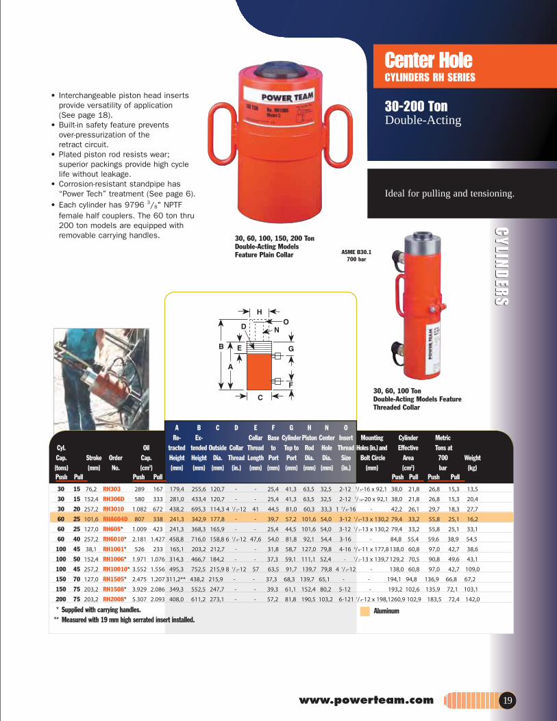
* Supplied with carrying handles.** Measured with 19 mm high serrated insert installed.
A B C D E F G H N ORe- Ex- Collar Base Cylinder Piston Center Insert Mounting Cylinder Metric
daerhTeloHdoRot poTotdaerhTralloCedistuOdednetdetcartliO.lyC Holes (in.)and Effective Tons atCap. Stroke Order Cap. Height Height Dia. Thread Length Port Port Dia. Dia. Size Bolt Circle Area 700 Weight
(tons) (mm) No. (cm3) (mm) (mm) (mm) (in.) (mm) (mm) (mm) (mm) (mm) (in.) (mm) (cm2) bar (kg)Push Pull Push Pull Push Pull Push Pull
30 15 76,2 RH303 289 167 179,4 255,6 120,7 - - 25,4 41,3 63,5 32,5 2-12 3/ 8-16 x 92,1 38,0 21,8 26,8 15,3 13,5
30 15 152,4 RH306D 580 333 281,0 433,4 120,7 - - 25,4 41,3 63,5 32,5 2-12 7/ 16-20 x 92,1 38,0 21,8 26,8 15,3 20,4
30 20 257,2 RH3010 1.082 672 438,2 695,3 114,3 4 1/ 2-12 41 44,5 81,0 60,3 33,3 1 7/ 8-16 - 42,2 26,1 29,7 18,3 27,7
60 25 101,6 RHA604D 807 338 241,3 342,9 177,8 - - 39,7 57,2 101,6 54,0 3-12 1/ 2-13 x 130,2 79,4 33,2 55,8 25,1 16,2
60 25 127,0 RH605* 1.009 423 241,3 368,3 165,9 - - 25,4 44,5 101,6 54,0 3-12 1/ 2-13 x 130,2 79,4 33,2 55,8 25,1 33,1
60 40 257,2 RH6010* 2.181 1.427 458,8 716,0 158,8 6 1/ 4-12 47,6 54,0 81,8 92,1 54,4 3-16 - 84,8 55,4 59,6 38,9 54,5
100 45 38,1 RH1001* 526 233 165,1 203,2 212,7 - - 31,8 58,7 127,0 79,8 4-16 5/ 8-11 x 177,8 138,0 60,8 97,0 42,7 38,6
100 50 152,4 RH1006* 1.971 1.076 314,3 466,7 184,2 - - 37,3 59,1 111,1 52,4 - 1/ 2-13 x 139,7 129,2 70,5 90,8 49,6 43,1
100 45 257,2 RH10010* 3.552 1.556 495,3 752,5 215,9 8 1/ 2-12 57 63,5 91,7 139,7 79,8 4 1/ 2-12 - 138,0 60,8 97,0 42,7 109,0
150 70 127,0 RH1505* 2.475 1.207 311,2** 438,2 215,9 - - 37,3 68,3 139,7 65,1 - - 194,1 94,8 136,9 66,8 67,2
150 75 203,2 RH1508* 3.929 2.086 349,3 552,5 247,7 - - 39,3 61,1 152,4 80,2 5-12 - 193,2 102,6 135,9 72,1 103,1
200 75 203,2 RH2008* 5.307 2.093 408,0 611,2 273,1 - - 57,2 81,8 190,5 103,2 6-121 1/ 4-12 x 198,1260,9 102,9 183,5 72,4 142,0
CYLIN
DER
SC
YLIND
ERS
Center Hole CYLINDERS RH SERIES
30-200 Ton Double-Acting
Ideal for pulling and tensioning.
30, 60, 100, 150, 200 TonDouble-Acting ModelsFeature Plain Collar
30, 60, 100 TonDouble-Acting Models FeatureThreaded Collar
Aluminum
19
• Interchangeable piston head insertsprovide versatility of application (See page 18).
• Built-in safety feature prevents over-pressurization of the retract circuit.
• Plated piston rod resists wear; superior packings provide high cyclelife without leakage.
• Corrosion-resistant standpipe has“Power Tech” treatment (See page 6).
• Each cylinder has 9796 female half couplers. The 60 ton thru200 ton models are equipped withremovable carrying handles.

L C2
RT 302
B AC1
ZZ
* Push side only for RT1004 double-acting cylinder.** The RT1004 has a bypass when full stroke is reached,
preventing over-pressurization of the cylinder.
NOTE: Each cylinder complete with threaded cylinder head insert, cylinder halfcoupler and cylinder attaching screws.
Single-Acting, Spring-Return Cylinders
Dimensions for reference only.
N HoleM Thd.
3/8
NPTFMountHole
80 803/8 NPTF
CYL
IND
ERS
171/2-100 Ton Single- Acting, Spring-Return & Double-Acting
Ideal for pulling and pressing.
A B C1 C2 L M N ZRe- Ex Out- Out- Load Load Center Mounting Cyl. Metric
Cyl. Oil tracted tended side side Cap Cap Hole Hole Mounting Eff. TonsCapacity Stroke Order Cap. Height Height Dia. Dia. Dia. Thread Dia. Location Hole Area at 700 Weight(Tons) (mm) No. (cm3) (mm) (mm) (mm) (mm) (mm) (in.) (mm) (mm) (mm) (cm2) bar (kg)
nruteRhsuPhsuP
17,5 50,8 RT172 116 - 174,6 225,4 95,3 146,1 44,5 1-8 27,0 38,1 8,7 22,8 16,1 6,630 63,5 RT302 258 - 214,3 277,8 108,0 190,5 57,2 1 1/4-7 32,9 46,0 11,9 40,5 28,5 12,850 76,2 RT503 482 - 268,3 344,5 149,2 238,1 73,0 1 5/8-5 1/2 42,5 60,3 16,7 63,3 44,5 25,4
100 123,8 RT1004** 1.5831.037 384,2 508,0 266,7 336,6 120,7 2 1/2-8 65,1 73,0 19,8 124,1* 87,3 72,6
• A proven design; used throughoutindustry for over 40 years.
• Cylinders withstand full “dead-end” loads.
• Compact design; ideal for applicationsin which space is limited.
• Basic head can be changed from atapped hole to plain hole by simplychanging insert.
• Pistons have “Power Tech” treatment for corrosion and abrasion resistance.
CYL
IND
ERS
Center HoleCYLINDERS RT SERIES
1
3
4
5
7
To use with RT172, RH203 RT302, RH302 RT503, RH503, RH603 RT1004606HR ,506HR603HR ,303HRoN .lyC
Order Set No. RHA20 RHA30 RHA50 RHA100 Speed Crank 1 24814 27198 29595 303785Speed Nut 2 302482 302483 33439 34136
1"-8 1 1/4"-7 1 5/8"-5 _" 2 1/2"-8Adjusting 3 32118 34758 32698 32699Screw 1"–8 508 mm Lg. 1 1/4"-7 x 609,6 mm Lg. 15/8"-5 1/2"x 762 mm Lg. 2 1/2 "-8 x 869,9 mm Lg.
Threaded 4 Order threaded insert for RH series cylinders with the accessory set.(See above)Insert Threaded insert supplied with RT series cylinders.Pushing 5 201923 34510 34755 -Adapter 1"-8, 12,7 mm 1 1/4"-7 x 19,1mm 1 5/8"-5 1/2" x 25,4 mm
dia. shank dia. shank dia. shankPushing 6 201454 34511 34756 -Adapter 1"-8, 19,5 mm 1 1/4"-7 x 25,4 mm 1 5/8"-5 1/2" x 31,7 mm
dia. shank dia. shank dia. shankJack Screw 7 24813 25931 32701 32702
1"-8 x 177,8 mm Lg. 1 1/4"-7 x 228,6 mm Lg. 1 5/ 8"-5 1/2" x 279,4 mm Lg. 2 1/2"-8 x 406,4 mm lg.Screw Cap 8 28228 28229 28230 -
1"-8 x 38,1 mm dia. 1 1/4"-7 x 44,4 mm dia 1 5/ 8"-5 1/2" x 571,5 mm Lg.
2
6
8
“CENTER-HOLE” CYLINDER ACCESSORIES (OPTIONAL)
“QUICK CHANGE” HEAD INSERTS FORRT SERIES CYLINDERS
Switch from a tapped hole to a plain hole quickly with these cylinder head inserts. They are held inplace with a socket screw. Plain hole permits use ofa speed nut for readjusting cylinder after extension.
For Use Threaded PlainWith: Order No.* Order No.RT172 21669 21714RT302 21873 21872RT503 22274 22275RT1004 24197 24196
* Provided with cylinder
Quick-ChangeInserts
20

www.powerteam.com
CYLIN
DER
SC
YLIND
ERS
Double ActingCYLINDERS RD SERIES
10-500 TonDouble Acting, Hydraulic-Return
A B C D E F G H J KBase Cylinder
Re- Ex- Out- Collar Thread to Piston Piston Rod Int. Piston LoadsnoT cirteM.ffE .lyCeroBpaC-orP doR dna )ni(doRot poTtroPhtgneLdaerhTedisdednetdetcartliO.lyC
Cap . Stroke Order Capacity Height Height Dia. Size Thread trusion Port Dia. Depth trusion Dia. Dia. Area at 700 Weight(tons) (mm) No. (cm3) (mm) (mm) (mm) (in.) (mm) (mm) (mm) (mm) (mm) (mm) (mm) (mm) (cm2) bar (kg)
Push Pull Push Pull Push Pull Push Pull
10 4 158,8 RD106 228 90 296,9 455,6 76,2 2 3/4-12 41,3 25,4 63,5 33,3 1-8 x 25,4 6,4 34,9 42,9 14,4 5,7 10,2 4,0 10,0
10 4 254,0 RD1010 366 144 398,5 652,5 76,2 2 3/4-12 41,3 25,4 63,5 33,3 1-8 x 25,4 6,4 34,9 42,9 14,4 5,7 10,2 4,0 12,7
25 8 158,8 RD256 528 166 314,3 473,1 101,6 4-12 41,3 25,4 63,5 54,0 1 1/2-16 x 25,4 9,5 54,0 65,1 33,2 10,4 23,4 7,3 18,1
25 8 362,0 RD2514 1.205 376 517,5 879,5 101,6 4-12 41,3 25,4 63,5 54,0 1 1/2-16 x 25,4 9,5 54,0 65,1 33,2 10,4 23,4 7,3 29,5
55 28 158,8 RD556 1.132 577 329,4 488,2 127,0 5-12 41,3 33,3 63,5 66,7 1 11/16-8 x 30,2 15,9 66,7 95,3 71,2 36,3 50,1 25,6 27,9
55 28 333,4 RD5513 2.376 1.212 504,0 837,4 127,0 5-12 41,3 33,3 63,5 66,7 1 11/16-8 x 30,2 15,9 66,7 95,3 71,2 36,3 50,1 25,6 40,9
55 28 460,4 RD5518 3280 1.673 657,2 1.117,6 127,0 5-12 41,3 33,3 63,5 66,7 1 11/16-8 x 30,2 15,9 66,7 95,3 71,2 36,3 50,1 25,6 64,5
80 44 333,4 RD8013 3421 1.901 517,5 850,9 146,1 5 3/4-12 41,3 38,1 63,5 76,2 2-4 1/2 x 38,1 14,3 73,0 114,3 102,6 57,0 72,1 40,1 53,6
100 44 168,3 RD1006 2.242 959 350,0 518,3 174,6 6 7/8-12 41,3 38,1 63,5 98,4 2 3/4-12 x 29,4 15,9 98,4 130,2 133,1 57,0 93,5 40,1 57,2
100 44 333,4 RD10013 4.440 1.902 515,1 848,5 174,6 6 7/8-12 41,3 38,1 63,5 98,4 2 3/4-12 x 29,4 15,9 98,4 130,2 133,1 57,0 93,5 40,1 82,2
100 44 511,2 RD10020 6.809 2.919 718,3 1.229,5 174,6 6 7/8-12 41,3 38,1 63,5 98,4 2 3/4-12 x 29,4 15,9 98,4 130,2 133,1 57,0 93,5 40,1 118,0
150 73 168,3 RD1506 3.334 1.606 377,8 546,1 209,6 8 1/4-12 41,3 50,8 63,5 114,3 3 1/4-8 x 38,1 20,6 114,3 158,8 197,9 95,3 139,1 66,9 85,4
150 73 333,4 RD15013 6.604 3.180 542,9 876,3 209,6 8 1/4-12 41,3 50,8 63,5 114,3 3 1/4-8 x 38,1 20,6 114,3 158,8 197,9 95,3 139,1 66,9 123,5
150 73 460,4 RD15018 9.132 4.392 673,9 1.134,3 209,6 8 1/4-12 41,3 50,8 63,5 114,3 3 1/4-8 x 38,1 19,1 114,3 158,8 197,9 95,3 139,1 66,9 170,7
200 113 168,3 RD2006 4.485 2.457 406,4 574,7 241,3 9 1/2-12 41,3 63,5 68,3 123,8 3 1/4-8 x 57,1 27,0 114,3 184,2 266,3 145,9 187,2 102,6 118,9
200 113 333,4 RD20013 8.886 4.869 571,5 904,9 241,3 9 1/2-12 41,3 63,5 68,3 123,8 3 1/4-8 x 57,1 27,0 114,3 184,2 266,3 145,9 187,2 102,6 161,6
200 113 460,4 RD20018 12.270 6.722 723,9 1.184,3 241,3 9 1/2-12 41,3 63,5 68,3 123,8 3 1/4-8 x 57,1 27,0 114,3 184,2 266,3 145,9 187,2 102,6 200,7
300 147 152,4 RD3006 5.920 2.903 488,9 591,3 273,1 10 1/2-12 60,3 85,7 85,7 158,8 2 1/2-12 x 82,5 28,6 174,6 222,3 387,8 190,0 272,7 133,6 172,5
300 147 330,2 RD30013 12.825 6.281 630,2 960,4 273,1 10 1/2-12 60,3 85,7 85,7 158,8 2 1/2-12 x 82,5 28,6 174,6 222,3 387,8 190,0 272,7 133,6 296,9
400 186 152,4 RD4006 7.724 4.051 489,7 642,1 320,7 12 1/2-8 69,9 97,6 97,6 184,2 3-12 x 92,2 31,8 198,4 254,0 506,6 240,3 356,2 169,0 265,6
400 186 330,2 RD40013 16.744 8.790 667,5 997,7 320,7 12 1/2-8 69,9 97,6 97,6 184,2 3-12 x 92,2 31,8 198,4 254,0 506,6 240,3 356,2 169,0 349,6
500 245 152,4 RD5006 9.774 4.838 522,3 674,7 374,7 14 3/4-8 79,4 105,6 105,6 203,2 3 1/4-12 x 107,9 38,1 215,9 285,8 641,1 317,0 450,8 222,8 371,8
500 245 330,2 RD50013 21.18910.480 700,1 1.030,3 374,7 14 3/4-8 79,4 105,6 105,6 203,2 3 1/4-12 x 107,9 38,1 215,9 285,8 641,1 317,0 450,8 222,8 495,8
• High tonnage premium design for high cycle life.• Perfect for bridge lifting, building reconstruction, shipyard, utility
and mining equipment maintenance. • Aluminum bronze overlay bearings provide long life, chrome
plated piston rod resist corrosion. • Load cap snaps out to expose internal piston rod threads
for pulling applications; threads withstand full tonnage.• Grooved ring pattern in load cap helps guard
against load slippage.• Each cylinder has two 9796 3/8" NPTF female half couplers.• Built-in safety relief valve prevents over-pressurization of the
retract circuit.• Feature mounting holes and collar threads.
Features of RD Series Cylinders
Heavy duty load capUrethane rod wiper and
seal with back-up
Built-in safety relief valve
Aluminum bronze overlaybearings for
extra-heavy wear
Chrome plated piston rod
“T” seal with back-ups
“O” ring with back-up
RD10013 ASME B30.1 700 bar
Tonnage 10 25 55 80 100 150 200 300 400 500No. of Holes 2 4 4 4 4 4 4 4 4 6Thread Size 3/8"-16 1/2"-13 5/8"-11 5/8"-11 3/4"-10 1"-8 11/4"-7 11/4"-7 11/2"-12 13/8"-12Depth (mm) 16 19 22 22 25 25 32 44 48 51B.C. Dia. 51 70 89 114 140 152 165 159 184 203Orientation 90° 45° 45° 45° 45° 45° 45° Random Random Random
BASE MOUNTING HOLES FOR "RD" CYLINDERSNOTE: Basemountingholes arestandard onall RD cylin-ders. Orientation of base mountingholes to coupler. Orientation onRD300, RD400 & RD500 series is random.
90˚45˚
SWIVEL CAPS (OPTIONAL)
Reduce the effects of off center loading.Tilts up to 5 degrees.
SwivelCylinder Cap Weight A B CTonnage Order No. (kg) (mm) (mm) (mm)
10 350144 0,4 22,2 36,5 21,8
25 350145 0,6 28,6 54 36,5
55 351325 1,9 61,9 63,5 39,3
100 351324 5,1 75,0 95,3 67,5
150 351334 5,8 66,7 111,1 77,8
SWIVEL CAPS FOR “RD” CYLINDERS
21

CYL
IND
ERS
High Tonnage CYLINDERS R SERIES
55-565 TonSingle-ActingLoad-Return
CYL
IND
ERS
R1502C
• Visible indicator band alerts whenstroke limit is reached; overflow port(“weep hole”) stroke limiter preventspiston from being overextended.
• Alloy heat treated piston and body for reliability and strength.
• Plated piston rod increase corrosionresistance and give superior bearing qualities.
ASME B30.1700 bar
A B C F H KBase Piston Piston
Cyl. Order Oil Retracted Extended Outside to Rod Rod Bore Effective Metric TonsCap. Stroke No. Cap. Ht. Ht. Dia. Port Dia. Protrusion Dia. Area at 700 Weight
(tons) (mm) (cm3) (mm) (mm) (mm) (mm) (mm) (mm) (mm) (cm2) bar (kg)55 50,8 R552C 362 125,4 176,2 127,0 25,4 95,3 3,2 95,3 71,2 50,1 12,355 152,4 R556C 1.087 227,0 379,4 127,0 25,4 95,3 3,2 95,3 71,2 50,1 22,755 254,0 R5510C 1.811 328,6 582,6 127,0 25,4 95,3 3,2 95,3 71,2 50,1 32,7100 50,8 R1002C 677 139,7 190,5 165,1 25,4 130,2 3,2 130,2 133,1 93,6 23,6100 152,4 R1006C 2.030 241,3 393,7 165,1 25,4 130,2 3,2 130,2 133,1 93,6 40,4150 50,8 R1502C 1.007 161,9 212,7 204,8 31,8 158,8 3,2 158,8 197,9 139,1 41,8150 152,4 R1506C 3.019 263,5 415,9 204,8 31,8 158,8 3,2 158,8 197,9 139,1 68,6150 254,0 R15010C 5.032 365,1 619,1 204,8 31,8 158,8 3,2 158,8 197,9 139,1 95,3200 50,8 R2002C 1.355 190,5 241,3 235,0 41,3 184,2 3,2 184,2 266,3 187,2 65,8200 152,4 R2006C 4.062 292,1 444,5 235,0 41,3 184,2 3,2 184,2 266,3 187,2 100,3355 50,8 R3552C 2.326 231,8 282,6 298,5 54,0 241,3 3,2 241,3 457,2 321,4 137,1355 152,4 R3556C 6.975 333,4 485,8 298,5 54,0 241,3 3,2 241,3 457,2 321,4 197,0355 254,0 R35510C 11.624 435,0 689,0 298,5 54,0 241,3 3,2 241,3 457,2 321,4 256,5430 50,8 R4302C 2.841 263,5 314,3 330,2 63,5 266,7 3,2 266,7 558,5 392,7 199,8430 152,4 R4306C 8.520 365,1 517,5 330,2 63,5 266,7 3,2 266,7 558,5 392,7 276,5565 50,8 R5652C 3.710 292,1 342,9 377,8 69,9 304,8 3,2 304,8 729,5 512,9 289,7565 152,4 R5656C 11.129 393,7 546,1 377,8 69,9 304,8 3,2 304,8 729,5 512,9 389,5565 254,0 R56510C 18.548 495,3 749,3 377,8 69,9 304,8 3,2 304,8 729,5 512,9 489,4
Recommended to use with swivel caps (optional) toreduce the effects of off center loading. Tilts up to 5degrees. Radial grooves on top of cap reduce load slip-page. Notch across face of each cap helps keep loadshaving a protruding or round shaped centered.
Use with Swivel Cap Weight A B Cyl. No. Order No. (kg) (mm) (mm)
55-100 ton 420866 0.8 25,4 71,4150-200 ton 420867 4,0 38,1 130,2
420868 6,1 44,5 149,2355 ton 420869 16,8 69,9 195,3
420870 23,6 79,4 225,4565 ton 420871 35,4 92,1 250,8
For use with “R _ _ _ _ C” cylinders
SWIVEL CAPS (Optional)
High-tonnage
43 ton
280 ton
0
22
Base Mounting Holes (Optional)Available on request: Up to 1140 tons capacity and Strokes: 101.6 mm, 203.2 mm & 304.8 mm

www.powerteam.com
CYLIN
DER
SC
YLIND
ERS
High Tonnage CYLINDERS R SERIES
100-565 TonDouble-Acting,Hydraulic-Return
High-tonnage,hydraulic return.
R2806D
R1502D
• Cylinders come standard with swivel capsto reduce the effects of off-center loading.
• Cylinders may be “dead-ended” without damage.
• Hard chrome plated, heat treated piston rod reduces wear on piston and gland nut.
• Built-in safety relief valve prevents over-pressurization of the retract circuit.
• Each cylinder has two 9796 3⁄8" NPTFfemale half couplers.
A B C F G H KRe- Ex- Base Cylinder Piston Piston Cylinder Metric
Cyl. Order Oil tracted tended Outside to Top to Rod Rod Bore Effective TonsCap. Stroke No. Capacity Height Height Dia. Port Port Dia. Protrusion Dia. Area at 700 Weight
(tons) (mm) (cm3) (mm) (mm) (mm) (mm) (mm) (mm) (mm) (mm) (cm2) bar (kg)hsuPhsuPnruteRhsuP
100 50,8 R1002D 676 315 168,7 219,5 165,1 25,4 56,0 95,3 7,1 130,2 132,9 93,4 24,5100 152,4 R1006D 2.027 945 270,3 422,7 165,1 25,4 56,0 95,3 7,1 130,2 132,9 93,4 36,8100 254,0 R10010D 3.378 1.574 371,9 625,9 165,1 25,4 56,0 95,3 7,1 130,2 132,9 93,4 49,0150 50,8 R1502D 1.007 485 188,9 239,7 204,8 31,8 57,2 114,3 7,5 158,8 198,0 139,1 43,1150 152,4 R1506D 3.021 1.456 290,5 442,9 204,8 31,8 57,2 114,3 7,5 158,8 198,0 139,1 61,7200 50,8 R2002D 1.355 643 206,8 257,6 235,0 41,3 58,7 133,4 8,7 184,2 266,4 187,2 61,7200 152,4 R2006D 4.064 1.929 308,4 460,8 235,0 41,3 58,7 133,4 8,7 184,2 266,4 187,2 84,9200 254,0 R20010D 6.773 3.214 410,0 664,0 235,0 41,3 58,7 133,4 8,7 184,2 266,4 187,2 108,5280 152,4 R2806D 5.579 2.322 335,4 447,8 276,2 47,6 65,5 165,1 10,3 215,9 365,7 257,3 134,8280 254,0 R28010D 9.299 3.870 437,0 691,0 276,2 47,6 65,5 165,1 10,3 215,9 365,7 257,3 170,7355 50,8 R3552D 2.326 777 288,9 339,7 298,5 54,0 69,9 196,9 11,1 241,3 457,3 321,4 147,0355 152,4 R3556D 6.977 2.332 390,5 542,9 298,5 54,0 69,9 196,9 11,1 241,3 457,3 321,4 191,1430 50,8 R4302D 2.840 977 312,7 363,5 330,2 63,5 75,0 215,9 11,9 266,7 558,6 392,7 199,3430 152,4 R4306D 8.521 2.932 414,3 566,7 330,2 63,5 75,0 215,9 11,9 266,7 558,6 392,7 253,3430 254,0 R43010D 14.202 4.887 515,9 769,9 330,2 63,5 75,0 215,9 11,9 266,7 558,6 392,7 305,5565 50,8 R5652D 3.710 1.260 345,3 396,1 377,8 69,9 81,4 247,7 13,9 304,8 729,5 512,9 281,0565 152,4 R5656D 11.129 3.779 446,9 599,3 377,8 69,9 81,4 247,7 13,9 304,8 729,5 512,9 350,4565 254,0 R56510D 18.548 6.298 548,5 802,5 377,8 69,9 81,4 247,7 13,9 304,8 729,5 512,9 420,4
Swivel cap(Standard)
23
Base Mounting Holes (Optional)Available on request: Up to 1140 tons capacity and Strokes: 101.6 mm, 203.2 mm & 304.8 mm

CYL
IND
ERS
CYL
IND
ERS
Locking CollarCYLINDER RL SERIES– ALUMINUM
55 & 100 TonSingle-Acting,Spring-Return
Positive mechanical lock to support load.
RA556L
RA1006L
• Support lifted load for extended periodsof time with hydraulic pressure released.
• At half the weight of steel cylinders ofcomparable capacity, aluminum cylindersare ideal when portability is a key factor.
• Feature carrying handle.
Locking collar featurepermits non-hydraulicsupport of load.
A B C F H K TBase Piston Piston Cylinder Metric
Cyl. Order Oil Retracted Extended Outside to Rod Rod Nut Bore Effective Tons atCap. Stroke No. Cap. Ht. Ht. Dia. Port Dia. ProtrusionThickness Dia. Area 700 Weight
(tons) (mm) (cm3) (mm) (mm) (mm) (mm) (mm) (mm) (mm) (mm) (cm2) bar (kg)
55 155,5 RA556L 1.109 317,5 473,1 133,4 34,9 82,6 12,7 38,1 95,3 71,2 50,1 13,4
100 158,8 RA1006L 2.116 339,7 498,5 187,3 30,2 114,3 6,4 38,1 130,2 133,0 93,5 29,1
ASME B30.1700 bar
Note: Supported loads not to exceed the rated capacity of the cylinders. Not intended to support additional dynamic loads, such as those applied by moving vehicles.
24
Swivel CapTonnage Order No.
55 Q99-1000 0,9 31,8 63,2 71,4
Wt. A B C (kg.) (mm) (mm) (mm)
SWIVEL CAPS reduce the effects ofoff center loading. Tilts up to 5º.
(Available as optional)

www.powerteam.com
CYLIN
DER
SC
YLIND
ERS
Locking CollarCYLINDER RL SERIES– STEEL
55-565 TonSingle-ActingLoad-Return
Positive mechanical lock to support load.
A B C F H K TcirteMrednilyCnotsiPnotsiPesaB
Cyl. Order Oil Retracted Extended Outside to Rod Rod Nut Bore Effective Tons atCap. Stroke No. Cap. Ht. Ht. Dia. Port Dia. Protrusion Thickness Dia. Area 700 Weight
(tons) (mm) (cm3) (mm) (mm) (mm) (mm) (mm) (mm) (mm) (mm) (cm2) bar (kg)55 50,8 R552L 362 161,9 212,7 125,4 25,4 95,3 3,2 36,5 95,3 71,2 50,1 15,355 152,4 R556L 1.087 263,5 415,9 125,4 25,4 95,3 3,2 36,5 95,3 71,2 50,1 26,355 254,0 R5510L 1.811 365,1 619,1 125,4 25,4 95,3 3,2 36,5 95,3 71,2 50,1 36,3100 50,8 R1002L 677 184,2 235,0 165,1 25,4 130,2 3,2 44,5 130,2 133,1 93,4 30,0100 152,4 R1006L 2.030 285,8 438,2 165,1 25,4 130,2 3,2 44,5 130,2 133,1 93,4 46,8100 254,0 R10010L 3.383 387,4 641,4 165,1 25,4 130,2 3,2 44,5 130,2 133,1 93,4 64,5150 50,8 R1502L 1.007 206,4 257,2 204,8 31,8 158,8 3,2 44,5 158,8 197,9 139,1 53,0150 152,4 R1506L 3.019 308,0 460,4 204,8 31,8 158,8 3,2 44,5 158,8 197,9 139,1 80,4200 50,8 R2002L 1.355 241,3 292,1 235,0 41,3 184,2 3,2 50,8 184,2 266,3 187,2 83,1200 152,4 R2006L 4.062 342,9 495,3 235,0 41,3 184,2 3,2 50,8 184,2 266,3 187,2 117,6280 50,8 R2802L 1.861 247,7 298,5 276,2 41,3 215,9 3,2 57,2 215,9 366,0 257,3 118,5280 152,4 R2806L 5.583 349,3 501,7 276,2 41,3 215,9 3,2 57,2 215,9 366,0 257,3 163,0280 254,0 R28010L 9.305 450,9 704,9 276,2 41,3 215,9 3,2 57,2 215,9 366,0 257,3 208,1355 50,8 R3552L 2.326 292,1 342,9 298,5 54,0 241,3 3,2 60,3 214,3 457,2 321,4 173,0355 152,4 R3556L 6.975 393,7 546,1 298,5 54,0 241,3 3,2 60,3 241,3 457,2 321,4 232,5430 50,8 R4302L 2.841 333,4 384,2 330,2 63,5 266,7 3,2 69,9 266,7 558,5 392,7 252,4430 152,4 R4306L 8.520 435,0 587,4 330,2 63,5 266,7 3,2 69,9 266,7 558,5 392,7 329,2430 254,0 R4310L 14.201 536,6 790,6 330,2 63,5 266,7 3,2 69,9 266,7 558,5 392,7 405,9565 50,8 R5652L 3.710 371,2 422,3 377,8 69,9 304,8 3,2 79,4 304,8 729,5 512,9 368,2565 152,4 R5656L 11.129 473,1 625,5 377,8 69,9 304,8 3,2 79,4 304,8 729,5 512,9 468,0565 254,0 R56510L 18.548 574,7 828,7 377,8 69,9 304,8 3,2 79,4 304,8 729,5 512,9 568,0
R15010L
• Support lifted load for extended periods of timewith hydraulic pressure released.
• Visible indicator band alerts when stroke limit isreached; overflow port (“weep hole”) stroke limiterprevents piston from being overextended.
• All cylinders feature coated pistons to resist corrosion and abrasion.
Locking collar feature permitsnon-hydraulic support of load.
ASME B30.1700 bar
Reduce the effects of offcenter loading. Tilts up to 5degrees. Radial grooves on topof cap reduce load slippage.
•NOTE: Supported loads not to exceed the rated capacity of the cylinders. Not intended to support additional dynamic loads, such as those applied by moving vehicles.
Use with Swivel Cap Weight A BCyl. No. Order No. (kg) (mm) (mm)
55-100 ton 420866 0.8 25,4 71,4150-200 ton 420867 4,0 38,1 130,2
420868 6,1 44,5 149,2355 ton 420869 16,8 69,9 195,3
420870 23,6 79,4 225,4565 ton 420871 35,4 92,1 250,8
SWIVEL CAPS (Optional)For use with “R _ _ _ _ L” cylinders
43 ton
280 ton
0
25
Base Mounting Holes (Optional)Available on request: Up to 1140 tons capacity and Strokes: 101.6 mm, 203.2 mm & 304.8 mm

CYL
IND
ERS
CYL
IND
ERS
Pancake Locking CollarCYLINDER PLC SERIES
67-565 Ton “Single-Acting,” Load-Return
Positive mechanical lock to support load. Ideal forconfined area applications.
26
• Compact design - for use where space is limited
• Locking collar designed to support lifted load for extended periods of time with hydraulic pressure released
• Overflow port (“weep hole”) prevents piston from being overextendedunder load.
• Special coating improves corrosion and abrasion resistance
• Cylinders come standard with hardened caps. Swivel caps reduce the effects of off-center loading and improves performance under side load.
• Equipped with 3/8” NPTF female half couplers
A
G
H
D
C
B
E
FIntegral Swivel Cap reduces the effects of off center loading.
Tilts up to 5 degrees.
Radial grooves on top of cap reduce load slippage.
A B D F CcirteMCylinderPiston
Cyl. Order Oil Retracted Extended Outside Rod Nut Bore Effective Tons atCap. Stroke No. Cap. Ht. Ht. Dia. Dia Thickness Dia. Area 700 Weight(tons) (mm) (cm3) (mm) (mm) (mm) (mm) (mm) (mm) (cm2) bar (kg) 67 50.8 PLC672 435 125.7 176.5 140.0 104.4 26.7 104.4 85.6 60 15.0 110 50.8 PLC1102 745 137.7 188.5 174.6 136.7 31.1 136.7 146.6 103 26.0 180 50.8 PLC1802 1,176 153.9 204.7 219.6 171.7 41.0 171.7 231.4 163 44.0 220 50.8 PLC2202 1,447 160.6 211.4 244.7 190.5 43.0 190.5 284.9 200 57.0 280 50.8 PLC2802 1,856 164.8 215.6 274.7 215.7 44.5 215.7 365.4 257 75.0 430 45 PLC4302 2,513 183.9 228.9 355.6 266.7 57.4 266.7 558.4 393 134.0 565 45 PLC5652 3,282 197.9 242.9 399.7 304.8 62.2 304.8 729.3 513 189.0

PU
MP
SP
UM
PS
www.powerteam.com
H I G H P E R F O R M A N C E P U M P S
PUMPS
Page
PA9…39Air Hydraulic
Page
Air Hydraulic
Page
P SERIES…36-38Hand Pumps
Page
VALVES…30-35,70
Page
PUMP BASICS…28-29
Page
PA46/55…45Air Hydraulic
Page
PE17…52Electric Hydraulic
Page
PUA, PMA…46-49Air Operated Pump
Page
PE10, PR10…50-51
Electric / Battery
Page
PE21…54Electric Hydraulic
Page
PE30…55Electric Hydraulic
Page
PA17…44Air Hydraulic
Page
PA50…42Air Hydraulic
Page
PA60…43Air Hydraulic
Page
PE46…57Electric Hydraulic
Page
PQ60…60Quiet Electric Hydraulic
Page
PE400…62Electric Hydraulic
Page
INTENSIFIER…56
Page
ACCESSORIES…66-69
Page
PG30/55…63Gasoline Driven
Page
PG120-PG400…64-65
Gasoline Driven
Page
PQ120…61Quiet Electric Hydraulic
Page
PE18…53Vanguard Jr.®
Electric Hydraulic
Page
PE55…58-59Vanguard® Electric
Hydraulic
27
PA6, PA6D…40-41

28
PU
MP
SP
UM
PS
CONSIDERATIONS:
What maximum system operating pressure (bar) is required? What volume of oil delivery is required? (For manual pumps, cm3 of oil per handle stroke; for powered pumps, l/min. of oil).Is a single- or 2-speed pump required? (2-speed pumps deliver high oil volume at low pressurefor rapid cylinder piston advance, then shift to to the high pressure, low volume stage under load).What is the preferred source of power?
a) Manual (hand or foot operated). Providesportability, can be used where electricity or shop air are not available.
b) Air/Hydraulic. Uses shop air or a portable aircompressor. Ideal for use in petrochemical, minesor other inflammable or explosive environments.
c) Electric /Hydraulic. What voltage is available?Is a battery operated pump preferred?
d) Gasoline Engine/Hydraulic. Powers high-outputpumps at remote job sites where air or electricityare unavailable.
Is portability of the pump a factor to consider?Will the pump be used intermittently, or will it need to provide high-cycle operation? Does the applicationrequire that the pump be capable of starting under load?Is fluid heat build-up a factor in your application? High cycle applications may require a larger capacity oilreservoir for cooling. Also, if you are using large displacement cylinders, the reservoir capacity must besufficient to fully extend the piston of the cylinder. Will the application require large displacement or multiplecylinders? Reservoir size and pump output levels will befactors to consider. Does the working environmentrequire a pump having a low operating noise (dBA) level?Must the pump operate in a spark-free environment?
Step 1 – Select the hydraulic cylinder that best suits the application (See page 9-24).
Step 2 – Select the series of hydraulic pump with adequate oil output and reservoir capacity to power
cylinder(See page 29, 36-45, 52-65).
Check speed/selection chart, consult factory.
Step 3 – Select pump within series with the valve option that is best suited to the cylinder and application
(See page 30-35, 70).
Choosing the Right Pump
Pump SelectionHIGH PERFORMANCE
Manually-operated Hydraulic Pumps(Hand Pumps)
spmuP ciluardyH nevird-enilosaGspmuP ciluardyH/cirtcelEspmuP ciluardyH/riA

www.powerteam.com 29
PU
MP
SP
UM
PS
P159
(2,2 l
Res.)
P460
(7,36 l
Res.)
PUMP SELECTION
HYDRAULIC
PUMP
OPTIONS
HandOperatedHydraulicPump
Two-Speed
(Provides
rapid
advance
to engage
load)
Single-Speed
(Best for
minimal
cylinder travel
before
engage load
High Volume
Pump
(for use
where air is
the preferred
power source)
Low Volume
Pump
(labor saving
alternative to
hand pumps
Stationary
Application:
Pump will
remain in one
location
performing
same task
Portable
Appliction:
Pump may
be moved
frequently to
perform task
Standard
(see
extension
cord
reference
chart)
Heavy Duty
(not effected
by frequent
starts and
stops)
PE17 •••
(4,7-6 l Res.
279 cm3/min.)
Cyl. 15 to
55 ton
PE10 §
(984 cm3 Res.164 cm3/min.)
Tools & Cyl. 5 to 25 ton
PE21 •••
(9,4 l Res. 344 cm3/min.)
Heavy Duty
PQ60 •••
(20 l Res. 984 cm3/min.)
Heavy Duty
PA6
(1,6 l Res. 98,4 cm3/min.)
Tools, smallpresses & cyl.
PA60
(6,8 l Res. 98,4 cm3/min.)Two-stage pump
PA17
(4,7 l Res. 278,8 cm3/min.)
P12
(148 cm3
Res.)
P55
(738 cm3
Res.)
P19
(328 cm3
Res.)
P19L
(443 cm3
Res.)
P59
(738 cm3
Res.)
P59L
(1082
cm3 Res.)
P157
(2,2 l
Res.)
PA46
(9,4 l Res. 754,4 cm3/min.)
PA55
(8,4 l Res. 902 cm3/min.)
PA9
(549 cm3 Res.148 cm3/min.)
Tools, small press-es & cyl.
PQ120 ****
(20 l Res. 1,92 l/min.) Heavy Duty
PE400 ****
(62,8 l Res. 6,7 l/min.) Heavy Duty
PE18 ^^
(1,6-8,4 l Res.295 cm3/min.)
Tools & Cyl. 10 to 25 ton
PE30 §
(4,5-6 l in. Res.)492 cm3/min.)
Tools & Cyl. 15 to 100 ton
PE46 •••
(9,4 l Res.
754 cm3/min.)
Cyl. 25 to
100 ton
PE60 ^^
(2,5 l Res. 984 cm3/min.)
Tools & Cyl. 55 to 100 ton
PE55 ^^
(8,4 l Res. 902 cm3/min.)
Tools & Cyl. 55 to 150 ton
PG30
(6 l Res. 7,8 l/min.)
Tools & 5-55 ton Cyl.
PG55
(21 l Res. 902 cm3/min.)
Tools & 15-100 ton Cyl.
PG120
(21 l Res. 1,9 l/min.)
MultipleCylinders
PG400
(63 l Res. 6,4 l/min.)
High Volume
PR10
(984 cm3 Res.164 cm3/min.)Tools & 5-25
ton Cyl.
AirPoweredHydraulicPump
ElectricPoweredHydraulicPump
GasPoweredHydraulicPump
BatteryPoweredHydraulicPump
Electric Motors:§ Permanent Magnet Motors, Single-phase^^ Universal Motors, Single-phase••• Induction Motors, Single-phase**** 3-phase Motors
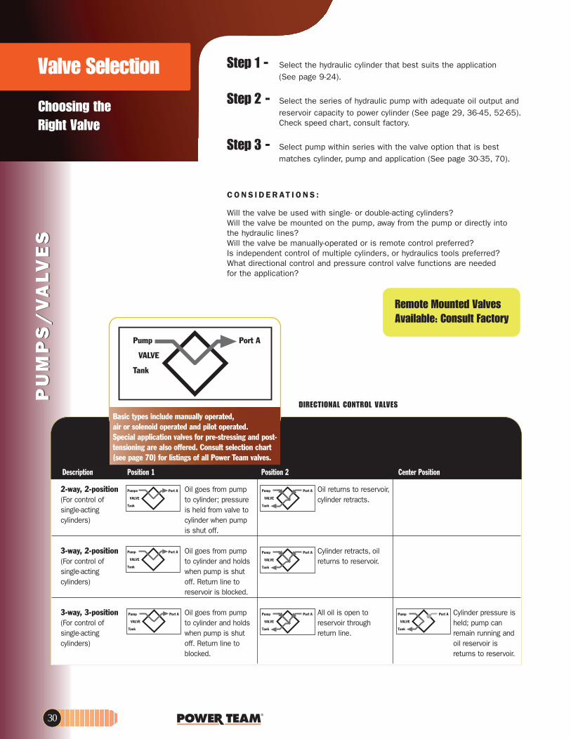
DIRECTIONAL CONTROL VALVESBasic types include manually operated, air or solenoid operated and pilot operated.
noitisoP retneC2 noitisoP1 noitisoPnoitpircseD
2-way, 2-position Oil goes from pump Oil returns to reservoir,.stcarter rednilyc erusserp ;rednilyc ot fo lortnoc roF(
ot evlav morf dleh signitca-elgnis pmup nehw rednilyc)srednilyc
is shut off.
3-way, 2-position Oil goes from pump Cylinder retracts, oil .riovreser ot snruter sdloh dna rednilyc otfo lortnoc roF(
tuhs si pmup nehwgnitca-elgnisot enil nruteR .ffo)srednilyc
reservoir is blocked.
3-way, 3-position si erusserp rednilyCot nepo si lio llApmup morf seog liOnac pmup ;dlehhguorht riovresersdloh dna rednilyc otfo lortnoc roF(
dna gninnur niamer.enil nrutertuhs si pmup nehwgnitca-elgnis si riovreser lio ot enil nruteR .ffo)srednilyc
blocked. returns to reservoir.
PU
MP
S/
VA
LVE
SP
UM
PS
/V
ALV
ES
Step 1 -
Step 2 -
Step 3 -
the hydraulic lines?
Is independent control of multiple cylinders, or hydraulics tools preferred?What directional control and pressure control valve functions are neededfor the application?
A troPpmuP
VALVE
Tank
Pump Port A
VALVE
Tank
Pump Port A
VALVE
Tank
Pump Port A
VALVE
Tank
Pump Port A
VALVE
Tank
Pump Port A
VALVE
Tank
Pump Port A
VALVE
Tank
Choosing the Right Valve
Valve Selection
Pumpe Port A
VALVE
Tank
Will the valve be mounted on the pump, away from the pump or directly into
Will the valve be manually-operated or is remote control preferred?
(See page 9-24).
Check speed chart, consult factory.
C O N S I D E R AT I O N S :
Select the hydraulic cylinder that best suits the application
Select the series of hydraulic pump with adequate oil output andreservoir capacity to power cylinder (See page 29, 36-45, 52-65).
Select pump within series with the valve option that is bestmatches cylinder, pump and application (See page 30-35, 70).
Will the valve be used with single- or double-acting cylinders?
30
Special application valves for pre-stressing and post-tensioning are also offered. Consult selection chart(see page 70) for listings of all Power Team valves.
Remote Mounted ValvesAvailable: Consult Factory

www.powerteam.com
PU
MP
S/
VA
LVE
SP
UM
PS
/V
ALV
ES
Choosing the Right Valve
Valve Selection
3/4-way, 2 position Oil goes to the Oil goes to the eht fo edis ”dnetxe“fo lortnoc roF( “retract” side of the morf lio ehT .rednilyc ro -elgnis cylinder, oil from the
edis ”tcarter“ eht gnitca-elbuod “extend” side returns .riovreser ot snruter)srednilyc to reservoir.
Cylinder holdswith pump shut off.
3/4-way, 3 position Oil goes to the Oil goes to the Holds pressure even eht fo edis ”dnetxe“ fo lortnoc roF( “retract” side of the if pump is running.
morf lio,rednilyc gnitca-elbuod cylinder, oil from the Oil from pump goesedis ”tcarter“ eht)srednilyc “extend” side returns through valve, back
returns to reservoir. to reservoir. to reservoir.Cylinder holds with pump shut off.
Other Valve CharacteristicsTandem Center – Closed Center – Open Center –
gnidloh nehw desUnehw desu yllareneGera strop rednilyC,tnemeriuqer a ton sisevlav elpitlum gninnur morf lio,dekcolb
gninnur nehw sa morf seires ni ot seog pmup etarapes owt.pmup enonehw desU .riovreser
hcus sloot ciluardyhgninnur sniamer pmup dna srettuc sa-enilosag :elpmaxE
.srepmirc.spmup nevird
DIRECTIONAL CONTROL VALVESBasic types include manually operated,
air or solenoid operated and pilot operated. Special application valves for pre-stressing
and post-tensioning are also offered. Consult selection chart (see page 70) for listings
of all Power Team valves.
Load Lowering Valve –Provides precision metering for controlled return of the cylinder piston.
Sequence Valve – Used when a cylinder in a multiple cylinder application must advancebefore any other.
Pressure Reducing Valve – Permits independent pressure controlto two or more clamping systems operated by a single power source.
Shut-off Valve – For fine metering of hydraulic oil.Several may be used to control multiplesingle-acting cylinders.
Check Valve – Permits flow of hydraulic oil in onedirection only.
Pressure Relief Valve – Used at remote locations in a hydraulic circuit where maximum pressure requirements are less than the setting of the basic overload valve in the pump.
Metering Valve – Restricts surges by restricting flow to acertain level; when flow subsides, valvereopens automatically. For systemsusing large cylinders or extendedlengths of hose.
Pressure Regulator Valve – Permits adjustment of operating pressures at various values below therelief valve setting of the pump.
Relief Valve – Protects a hydraulic system againstover pressurization.
A troPpmuP
VALVE
Tank
Pump Port A
VALVE
Tank Port B
Pump Port A
VALVE
Tank Port B
Pump Port A
VALVE
Tank Port B
Pump Port A
VALVE
Tank Port B
Pump Port A
VALVE
Tank Port B
Pump Port A
VALVE
Tank
Pump Port A
VALVE
Tank Port B
Pump Port A
VALVE
Tank
IN-LINE HYDRAULIC VALVES (see page 78-79)
31

PU
MP
S/
VA
LVE
SP
UM
PS
/V
ALV
ES
ValvesHYDRAULIC PUMP MOUNTED
9517
9584
9582
P T
A
NOTE: A pressure switch and/or gauge may be attached to any valve on this page. (refer to page 67, 74-75)Gauge ports monitor pump pressure only, not pressure to the hydraulic cylinder(s).
CAUTION: To prevent sudden, uncontrolled descent of a load as it is being lowered, use a No. 9596 Load Lowering Valve or No. 9720 Counter Balance Valve (see page 78) in conjunction with the directional valve used in your application.
IMPORTANT: Conversion kit 251528 must be used when mounting any of the valves on this page on PA17 or PE17 pumps.IMPORTANT: When ordering any valve for a PE30 or PG30 series pump, 1/2" longer mounting screws are required. For valves 9584, 9502 and 9520, order four 12001 cap screws.
For valve 9582, order two 12001 and two 10856 cap screws.
3-WAY/2-POSITION MANUAL VALVESApplications – Single-acting cylinders. Actuation – Lever operated.Functions – Cylinder piston “advance”, “hold” and “return”.Used on these pumps – P460, PE17, PE21, PE30, PE46, PE55, PE84, PE90, PE120, PQ60 and PQ120 series.No. 9582 – 3-way/2-position manual valve. Wt. 1,13 kg.No. 9584 – Same as 9582, but has "flipper" control. Wt.,0,8 kg.
2-WAY/2-POSITION MANUAL VALVEApplication – Single-acting cylinders. Actuation – Flipper lever operated.Functions – Cylinder piston “advance”, “hold” and “retract”.Used on these pumps – PE172, PA172 and PE84 series.No. 9517 – 2-way/2-position manual valve. Wt.,1,45 kg.
3-WAY/3-POSITION (CLOSED CENTER) NON-INTERFLOW MANUAL VALVE WITH “POSI-CHECK®”Application – Single-acting cylinders. Actuation – Lever operated, detent positioned.Functions – Pos. 1 – Oil is directed from pump to cylinder and “holds” with pump shut off; line to reservoir is blocked. Pos. 2 – All oil is open to reservoir through tank line.Center pos. – Cylinder pressure is held; pump should be shut off.Used on these pumps – P460, PA17, PA46, PA55, PA60, PE17, PE21, PE30, PE46, PE55, PE84, PE90,PE120,PE200, PE400, PQ60 and PQ120 series.NOTE: The 9502 can be remote mounted if a 9510 subplate is used (see page 67).
No. 9502 – 3-way/3-position (closed center) manual valve. Wt.,1,9 kg.
3-WAY/3-POSITION (TANDEM CENTER) MANUAL VALVE WITH “POSI-CHECK®”Application – Single-acting cylinders.Actuation – Lever operated, detent positioned.Functions – “Advance” “hold” and “return”. When shifted to “return” position, pump and cylinder return oil throughtheir own separate return lines, allowing faster retraction of piston. The “Posi-Check®” feature guards against pressure loss when shifting from “advance” to “hold” position.Used on these pumps – P460, PA17, PA46, PA55, PE17, PE21, PE30, PE46, PE55, PE84, PE90, PE120, PQ60,PQ120, PE200, PE400, PG30, PG55, PG120 and PG400 series.No. 9520 – 3-way/3-position (tandem center) manual valve. Wt., 2,3 kg.
Pump Port A
VALVE
Tank
Pump Port A
VALVE
Tank
9520
Pump Port A
VALVE
Tank
ADVANCE
HOLD
RETRACT
P T
A9502
Pump Port A
VALVE
Tank
700 bar, 3/8" ports, 19 l/minmax flow rate.
Manual3 Way/2-3 Position Manual
32

www.powerteam.com
PU
MP
S/
VA
LVE
SP
UM
PS
/V
ALV
ES
700 bar, 3/8" ports, 19 l/minmax flow rate.
ValvesHYDRAULIC PUMP MOUNTED
4 Way/3 Position Manual
POS. B
POS. C
POS. A
P T
POS. B
POS. C
POS. A
P T
9500
9506
POS. B
POS. C
POS. A
P T
P T
A B
9507
P T
A B
POS. B
POS. C
POS. A
P T
P T
A B
9501
Port APort B
Port APort B
Port APort B
Port APort B
NOTE: A pressure switch and/or gauge may be attached to valves 9500, 9501, 9506, 9507, 9511 if desired (see page 67, 74-75). Gauge ports monitor pump only, not pressure to the hydraulic cylinder(s).Also, all valves on this page may be remote mounted with a 9510 subplate (see page 67).NOTE: Valves 9500, 9501, 9506 and 9507 can have a port blocked or have a closed center position for use with single-acting cylinder or tool. When a port is blocked and the valve is shifted to the blocked port, the pump will generate excessive heat. An electric or rotary air pump can either be turned off manually or with a pressure switch. Reciprocating air pumps may be adjusted to stall out and stop.
4-WAY/3-POSITION (TANDEM CENTER) VALVE WITH “POSI-CHECK®”Application – Single or double-acting cylinders.Actuation – Lever operated, detent positioned.Functions – “Advance”, “hold” and “return”. The “Posi-Check®” feature guardsagainst pressure loss when shifting from “advance” to “hold” position.Used on these pumps – P460, PA6D, PA17, PA46, PA55, PE17, PE21, PE30,PE46, PE55, PE84, PE90, PE120, PE200, PE400, PED, PG30, PG55, PG120,PG400, PQ60 and PQ120 seriesNo. 9506 – 4-way/3-position (tandem center) manual valve. Wt., 2,3 kg.
4-WAY/3-POSITION (TANDEM CENTER) MANUAL VALVEApplication – Single- or double-acting cylinders. Actuation – Lever operated, detent positioned.Functions – The 9500 provides “advance”, “hold” and “return”.Used on these pumps – P460, PA17, PA46, PA55, PE17*, PE21, PE30, PE46,PE55, PE84, PE90, PE120, PE200, PE400, PG30, PG55, PG120, PG400, PQ60and PQ120 series. *Does not mount without 251528
No. 9500 – 4-way/3-position (tandem center) manual valve. Wt., 1,9 kg.
4-WAY/3-POSITION (CLOSED CENTER) MANUAL VALVE WITH “POSI-CHECK®”Application – Single- or double-acting cylinders. Actuation – Lever operated, detent positioned.Functions – Similar to 9506, but is a closed center valve with “Posi-Check®”.Generally used to operate multiple cylinders with a single pump. Provides“advance”, “hold” and “return”. The “Posi-Check®” feature guards against pressure loss when shifting from the “advance” to “hold” position. See notebelow regarding plugging of ports and resulting heat build-up.Used on these pumps – P460, PA17, PA46, PA55, PA60, PA6D, PE17, PE21,PE30, PE46, PE55, PE84, PE90, PE120, PE200, PE400, PQ60 and PQ120 series.No. 9507 – 4-way/3-position (closed center) manual valve. Wt., 2,3 kg.
4-WAY/3-POSITION (CLOSED CENTER) MANUAL VALVEApplication – Single- or double-acting cylinders. Actuation – Lever operated, detent positioned. Functions – “Advance”, “hold” and “return”. Closed center design makes valve suitable for operating multiple cylinders from a single pump. See note below regarding plugging of ports and resulting heat build-up.Used on these pumps – P460, PA17, PA46, PA55, PA60, PE17, PE21, PE30,PE46, PE55, PE84, PE90, PE120, PE200, PE400, PQ60 and P120 series.No. 9501 – 4-way/3-position (closed center) valve. Wt., 1,9 kg.
Pump Port A
VALVE
Tank Port B
Pump Port A
VALVE
Tank Port B
Pump Port A
VALVE
Tank Port B
Pump Port A
VALVE
Tank Port B
P T
A B
33

PU
MP
S/
VA
LVE
S
700 bar., 3/8" ports, 19 l/minmax flow rate.
PU
MP
S/
VA
LVE
SValvesHYDRAULIC PUMP MOUNTED
Solenoid or Air Operated
9592, 9552, 9572
P T
A9579, 9569, 9570
CAUTION: To prevent sudden, uncontrolled descent of a load as it is being lowered, use a No. 9596 Load Lowering Valve or No. 9720 Counter BalanceValve (see page 78) in conjunction with the directional valve used in your application.IMPORTANT: Conversion kit 251528 must be used when mounting any of the valves on this page on PE17 pumps.IMPORTANT: When ordering any valve for a PE30 series pump, 1/2" longer mounting screws are required. For valves 9569, 9570 and 9579, order four 10856cap screws. For valves 9552, 9572 and 9592, order four 12001 cap screws.
3-WAY/2-POSITION SOLENOID VALVEApplication – Single-acting cylinders. Actuation – Solenoid operated, 115 volt, 50/60 Hz.Functions – Cylinder piston advances when solenoid is de-energized and pumpis running. When solenoid is energized, oil is directed to reservoir, and pistonreturns. For “hold” position, pump is stopped with solenoid de-energized.Used on these pumps – PE17, PE21, PE30, PE46, PE55, PE84, PE90,PE120, PE200, PE400, PQ60 and PQ120 series.No. 9579 – 3-way/2-position solenoid valve, 115 volt, 50/60 Hz. Wt., 4,4 kg.No. 9569 – Same as 9579, except with 24 volt, 50/60 Hz solenoid.No. 9570 – Same as 9579 except with 230 volt, 50/60 Hz solenoid.NOTES: Valves above are shipped without control switch. Use 202777 remote hand switch(see page 66). When this valve is mounted, the pump must be equipped with an outletcheck valve.
3/4-WAY/2-POSITION SOLENOID VALVESApplication – Single- or double-acting cylinders. When used with single-actingcylinders, one port should be plugged.Actuation – Solenoid operated.Functions – Oil is directed to “extend” side of cylinder, oil from “retract” sidegoes to reservoir; cylinder “holds” with pump shut off. Oil is directed to“retract” side of cylinder; oil from “extend” side goes to reservoir.NOTE: Cylinder will not “hold” in the “return” position with motor running or shut off.Used on these pumps – 9552, 9572 and 9592 are used with PE17, PE30(with carrying handles removed), PE46, PE55, PE84, PE90, PE200, PE400,PQ60 and PQ120 series.No. 9592 – 3/4-way/2-position solenoid valve, 115 volt, 50/60 Hz. Wt., 6,6 kg.No. 9552 – Same as 9592, except with 230 volt, 50/60 Hz solenoid.No. 9572 – Same as 9592, except with 24 volt, 50/60 Hz solenoid.NOTE: Valves above are shipped without controls. The 9552, 9572 and 9592 can be usedwith the 304718 remote hand control. (see page 66)Note: Ports are 1/4" NPTF.
AIR ACTUATED VALVEApplication – Single- or double-acting cylinders. When used with single-actingcylinders, one port should be plugged. Actuation – Air operated.Functions – Oil is directed to “extend” side of cylinder, oil from “retract” sidegoes to reservoir; cylinder “holds” with pump shut off. Oil is directed to“retract” side of cylinder; oil from “extend” side goes to reservoir.NOTE: Cylinder will not “hold” in the “return” position with motor running or shut off.Used on these pumps – PA17, PA46 and PA55 series.No. 9594 – 3/4-way/2-position solenoid valve, air operated (minimum of 3.5 bar air pressure required). Wt., 5 kg.NOTES: Valve above is shipped without controls. 9594 can be used with the 209593 remotehand control (see page 66).
A
B .LOSA .LOS
P T
Pump Port A
VALVE
Tank
Pump Port A
VALVE
Tank Port B
P T
A B
Pump Port A
VALVE
Tank Port B
9594 (for air actuation)
34

www.powerteam.com
9605, 9599
3-WAY/3-POSITION (TANDEM CENTER) SOLENOID VALVES WITH“POSI-CHECK®”Application – Single-acting cylinders. Actuation – Solenoid operated: 9605 is 115 volt, 50/60 Hz; 9599 is 24 volt, 50/60 Hz.Functions – “Advance”, “hold” and “return” positions. When in “advance”,solenoid “B” is energized and oil goes from pump to cylinder through pressure port. In “return” position, solenoid “A” is energized and oil is directed from cylinder andpump to reservoir. With both solenoids de-energized, in “hold” position, oil from pumpis directed back to reservoir while oil is checked in cylinder. The “Posi-Check®” featureholds load when shifting from “advance” to “hold” position.Used on these pumps – Furnished with pilot lines and adapters for PE55, PE30 (carrying handles must be removed) and PE120 series. For application on other models, consult factory.No. 9605 – 3-way/3-position (tandem center) solenoid valve, 115 volt, 50/60 Hz. Wt., 6,4 kg.No. 9599 – Same as 9605 except for 24 volt, 50/60 Hz circuits.
NOTE: Valves above are shipped without controls. Use 202777 remote hand control (see page 55).Consult factory for field installation.
700 bar, 3/8” ports, 19 1/minmax flow rate.
Solenoid Operated
ValvesHYDRAULIC PUMP MOUNTED
PU
MP
S/
VA
LVE
SP
UM
PS
/V
ALV
ES
9513, 9512, 9516, 9519
Port A
Port B
P T
A B
4-WAY/3-POSITION (TANDEM CENTER) PILOT OPERATEDSOLENOID VALVEApplication – Double-acting cylinders.Actuation – Solenoid operated, 115 volt, 50/60 Hz.Functions – “Advance”, “hold” and “return”. The “Posi-Check®” feature holdsthe load when shifting from the “advance” to the “hold” position.Used on these pumps – PE17, PE21, PE30 (with carrying handles removed),PE46, PE55, PE84, PE90, PE120, PE200, PE400, PQ60 and PQ120 series.
NOTE: A gauge may be attached if desired (see page 60-61).
No. 9513 – 4-way/3-position (tandem center) solenoid valve, 115 volt, 50/60Hz. Wt., 8,2 kg.No. 9512 – Same as 9513 except for 24 volt, 50/60 Hz circuits.No. 9516 – Same as 9513 except for 12 volt DC. For use on the PG1204Sand PG400 series pumps only.No. 9519 – Same as 9513 except for 230 volt, 50/60 Hz circuits. Consult fac-tory for field installation.
Pump Port A
VALVE
Tank Port B
NOTE: Valves above are shipped without control switch. Use 202778 remote hand switch (see page 55).
CAUTION: To prevent sudden, uncontrolled descent of a load as it is being lowered, use a No.9596 Load Lowering Valve or No. 9720 Counter Balance Valve (see page 64) in conjunction with thedirectional valve used in your application.IMPORTANT: When ordering any valve for a PE30 series pump, 1/2" longer mounting screws arerequired. For valves 9512, 9513, 9516 and 9519, order four 11956 cap screws.
P T
A
Pump
VALVE
Tank
Port A
9605, 9599
3-WAY/3-POSITION (TANDEM CENTER) SOLENOID VALVES WITH“POSI-CHECK®”Application – Single-acting cylinders. Actuation – Solenoid operated: 9605 is 115 volt, 50/60 Hz; 9599 is 24 volt, 50/60 Hz.Functions – “Advance”, “hold” and “return” positions. When in “advance”,solenoid “B” is energized and oil goes from pump to cylinder through pressure port. In “return” position, solenoid “A” is energized and oil is directed from cylinder andpump to reservoir. With both solenoids de-energized, in “hold” position, oil from pumpis directed back to reservoir while oil is checked in cylinder. The “Posi-Check®” featureholds load when shifting from “advance” to “hold” position.Used on these pumps – Furnished with pilot lines and adapters for PE55, PE30 (carrying handles must be removed) and PE120 series. For application on other models, consult factory.No. 9605 – 3-way/3-position (tandem center) solenoid valve, 115 volt, 50/60 Hz. Wt., 6,4 kg.No. 9599 – Same as 9605 except for 24 volt, 50/60 Hz circuits.
NOTE: Valves above are shipped without controls. Use 202777 remote hand control (see page 66).Consult factory for field installation.
700 bar, 3/8” ports, 19 1max flow rate.
Solenoid Operated
ValvesHYDRAULIC PUMP MO
9513, 9512, 9516, 9519
Port A
Port B
P T
A B
4-WAY/3-POSITION (TANDEM CENTER) PILOT OPERATEDSOLENOID VALVEApplication – Double-acting cylinders.Actuation – Solenoid operated, 115 volt, 50/60 Hz.Functions – “Advance”, “hold” and “return”. The “Posi-Check®” feature holdsthe load when shifting from the “advance” to the “hold” position.Used on these pumps – PE17, PE21, PE30 (with carrying handles removed),PE46, PE55, PE84, PE90, PE120, PE200, PE400, PQ60 and PQ120 series.
NOTE: A gauge may be attached if desired (see page 74-75).
No. 9513 – 4-way/3-position (tandem center) solenoid valve, 115 volt, 50/60Hz. Wt., 8,2 kg.No. 9512 – Same as 9513 except for 24 volt, 50/60 Hz circuits.No. 9516 – Same as 9513 except for 12 volt DC. For use on the PG1204Sand PG400 series pumps only.No. 9519 – Same as 9513 except for 230 volt, 50/60 Hz circuits. Consult fac-tory for field installation.
Pump Port A
VALVE
Tank Port B
NOTE: Valves above are shipped without control switch. Use 202778 remote hand switch (see page 66).
CAUTION: To prevent sudden, uncontrolled descent of a load as it is being lowered, use a No.9596 Load Lowering Valve or No. 9720 Counter Balance Valve (see page 78) in conjunction with thedirectional valve used in your application.IMPORTANT: When ordering any valve for a PE30 series pump, 1/2" longer mounting screws arerequired. For valves 9512, 9513, 9516 and 9519, order four 11956 cap screws.
P T
A
Pump
VALVE
Tank
Port A
35

PU
MP
SP
UM
PS
Hand PumpHYDRAULIC P SERIES
197 to 902 cm 3 ReservoirSingle-SpeedSingle-Acting
Best suited for applications wherethere is little or no free travel.
P55
P23
P12
700 bar
P55 Hand Pump on anair-craft towbar
Power Team hand pumps,with the angled fill port, havea built in "relief valve" pro-tection system. This systemis designed to protect over-pressurization of the reser-voir from sudden back pres-sure. This system alsoworks as a seal to preventoil leaks.
LP = Low PressureHP = High Pressure
* Pump includes 2-Way Valve
riovreseRerusserP & emuloV tcudorP liO liO elbasUliO eldnaHmumixaM rep emuloV roF
Use Order Stroke (cm3) Pressure (bar) Effort Capacity Capacity Port Weight With No. Speed LP HP LP HP (kg) (cm3) (cm3) (in) (kg))
Single P12 1 — 1,1 — 700 34 197 148 3/8-NPTF 2,6Acting P23 1 — 2,6 — 210 32 390 333 3/8-NPTF 5,5Cylinders* P55 1 — 2,6 — 700 66 902 738 3/8-NPTF 7,2
Pump A B C D E F G H J K L M NNo. (mm) (mm) (mm) (mm) (mm) (mm) (mm) (mm) (deg.) (mm) (mm) (in) (mm)
P12 101,6 — — 101,6 342,9 85,7 55,6 — 45° 4,8 85,7 3/8-NPTF 28,6* P23 158,8 330,2 88,9 141,3 346,1 108,0 82,6 261,6 38° 7,9 120,7 3/8-NPTF 41,3 * The P23 pump maximum pressure is 210 bar only.
P55 165,1 533,4 88,9 141,3 584,2 108,0 82,6 501,7 38° 7,9 120,7 3/8-NPTF 41,3
• All metal construction, won't burn through in welding environments.
• Formed metal handle provides less flex,and reduces operator fatigue.
• Convenient fill port on P23 and P55 allows pumps to be filled in a horizontal or vertical position.
• Fill cap seal acts as safety valve preventing over-pressurizing of reservoir.
• Relief valve inboard of check valve prevents loads from drifting down.
• Large valve knob gives added control for slowly metering loads down.
• Carrying handle (P55).
36
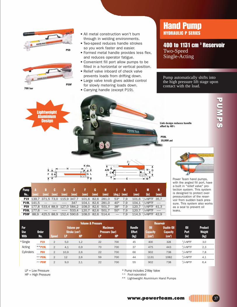
PU
MP
SP
UM
PS
www.powerteam.com
Hand PumpHYDRAULIC P SERIES
Pump automatically shifts into the high pressure lift stage uponcontact with the load.
400 to 1131 cm 3 ReservoirTwo-Speed Single-Acting
P59F
P59
700 bar
• All metal construction won't burn through in welding environments.
• Two-speed reduces handle strokesso you work faster and easier.
• Formed metal handle provides less flex,and reduces operator fatigue.
• Convenient fill port allow pumps to be filled in a horizontal or vertical position.
• Relief valve inboard of check valve prevents loads from drifting down.
for slowly metering loads down.
LP = Low PressureHP = High Pressure
* Pump includes 2-Way Valve^^ Foot-operated** Lightweight Aluminium Hand Pumps
riovreseRerusserP & emuloV tcudorPliO liO elbasU liO eldnaHmumixaM rep emuloV roF
Use Order Stroke (cm3) Pressure (bar) Effort Capacity Capacity Port WeightWith No. Speed LP HP LP HP (kg) (cm3) (cm3) (in) (kg)
*Single P19 2 5,0 1,2 22 700 45 400 328 3/8-NPTF 3,0
Acting **P19L 2 4,1 0,9 70 700 37 475 443 3/8-NPTF 2,3
Cylinders P59 2 10,9 2,6 22 700 66 902 738 3/8-NPTF 7,8
** P59L 2 12 2,6 59 700 44 1131 1082 3/8-NPTF 4,1
^^ P59F 2 9,0 2,1 22 700 55 902 738 3/8-NPTF 6,4
Power Team hand pumps,with the angled fill port, havea built in "relief valve" pro-tection system. This systemis designed to protect over-pressurization of the reser-voir from sudden back pres-sure. This system also worksas a seal to prevent oilleaks.
Pump A B C D E F G H J K L M NNo.. (mm) (mm) (mm) (mm) (mm) (mm) (mm) (mm) (deg.) (mm) (mm) (in) (mm)P19 139,7 371,5 73,0 115,9 347,7 101,6 82,6 281,0 53° 7,9 101,6 3/8-NPTF 35,7P19L 141,5 ---- ------ ------- 347 104,1 82,6 281,0 40° 7,9 104,1 3/8-NPTF ------P59 177,8 533,4 88,9 127,0 584,2 108,0 82,6 501,7 38° 7,9 120,7 3/8-NPTF 41,3P59L 177,6 ----- ------ -------- 533,4 120,7 82,6 501,7 50° 7,9 120,7 3/8-NPTF ------P59F 88,9 425,5 88,9 152,4 590,6 108,0 82,6 514,4 — 7,9 114,3 3/8-NPTF 42,9
P59L10,000 psi
LightweightAluminium
Design
• Large valve knob gives added control
• Carrying handle (except P19).
Link design reduces handleeffort by 40%
37

PU
MP
SP
UM
PS
Pump automatically shifts into the high pressure lift stage uponcontact with the load.
2,5 l to 9,5 l ReservoirTwo-Speed Single- and Double-Acting
Hand PumpHYDRAULIC P SERIES
P157/P159
P460
P300
FK59FK159B
riovreseR erusserP & emuloV tcudorP liOliO elbasU liO eldnaHmumixaM rep emuloV roF
Use Order Stroke (cm3) Pressure (bar) Effort Capacity Capacity Port Weight With No. Speed LP HP LP HP (kg) (cm3) (cm3) (in) (kg)
* Single- P157 2 10,7 2,6 97 700 64 2491 2245 3/8-NPTF 11,8Acting P159 2 42,6 2,6 22 700 64 2491 2245 3/8-NPTF 11,8Cylinders P300 2 42,6 2,6 22 700 64 5.700 5081 3/8-NPTF 25,1
P460 2 120,5 4,8 22 700 41 9.500 7539 3/8-NPTF 24,9** Double- P157D 2 10,7 2,6 97 700 64 2491 2245 3/8-NPTF 13,1
Acting P159D 2 42,6 2,6 22 700 64 2491 2245 3/8-NPTF 12,7Cylinders P300D 2 42,6 2,6 22 700 64 5.700 5081 3/8-NPTF 25,9
P460D 2 120,5 4,8 22 700 41 9.500 7539 3/8-NPTF 26,3
LP = Low PressureHP = High Pressure
* Pump includes 2-Way Valve** Pump includes 4-Way Valve
P300 hand pump and 10 ton cylinders usedfor a vehicle lift.
Pump A B C D E F G H J K L M N PNo. (mm) (mm) (mm) (mm) (mm) (mm) (mm) (mm) (deg.) (mm) (mm) (in) (mm)
P157/P159 197 521 123,8 175 578 98,4 76,2 502 39° 7,9 95,3 3/8-NPTF 57,2 — P300 210 533 114,3 175 575 215,9 190,5 526 39° 7,9 95,3 3/8-NPTF 57,2 — P460 283 787 171,5 289 610 743 279,4 229 80° 241,3 — 3/8-NPTF — 1/4 NPTF
Foot pump conversion kitNo. FK59 - Foot pump
conversion kit for use on P55/P59 pumps.Wt., 2,7 kg
No. FK159B - Foot pump conversion kit for use on P157/P159 and P300/P300D pumps.Wt., 2,7kg.
• Rugged all metal construction for strength and durability that won’t burn through in welding environments.
• Heavy-duty, formed metal handle provides less flex, and less operator fatigue than round or composite handles.
• Convenient fill port allows pumpson P157 and P159 to be filled in a horizontal or vertical position.
• Fill cap seal acts as safety valve to prevent over-pressurizing of reservoir.
• Relief valve inboard of check valve prevents loads from drifting down.
• Large valve knob gives added control
• Carrying handlefor slowly metering loads down.
.
38
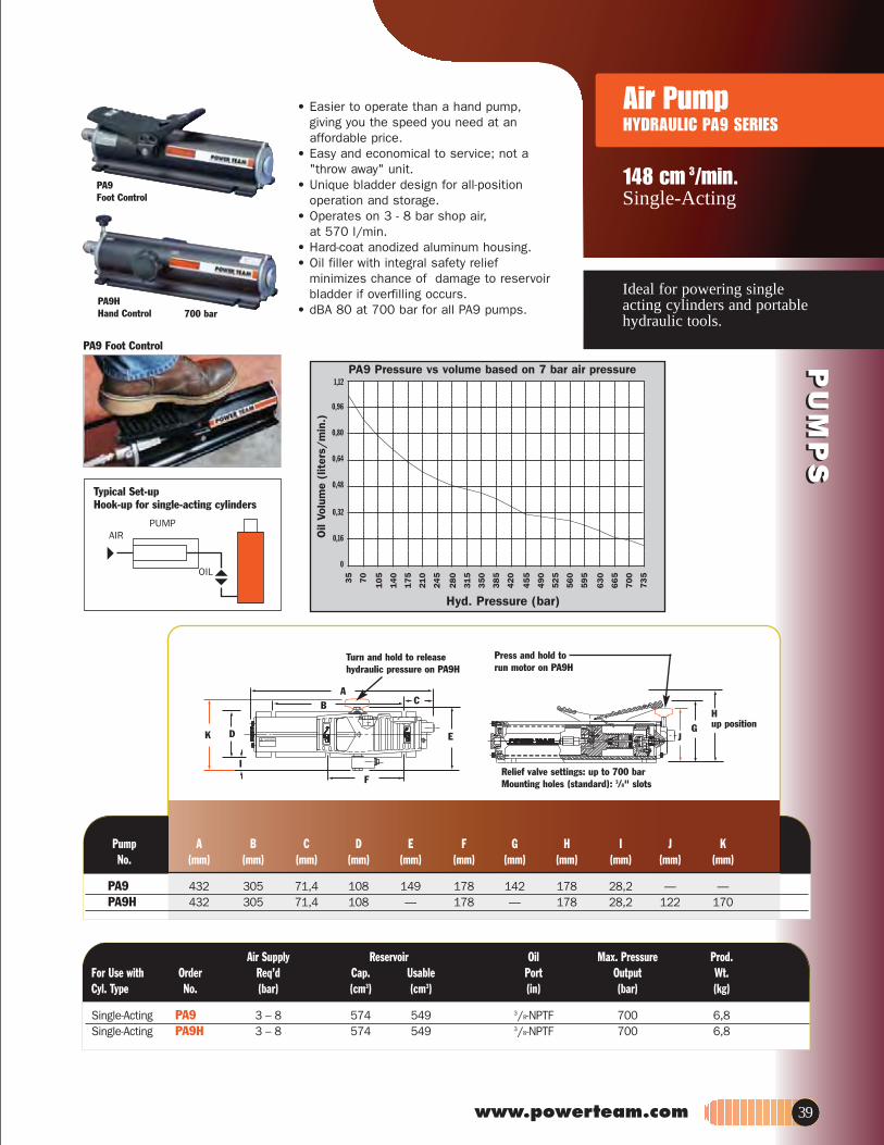
www.powerteam.com
PU
MP
SP
UM
PS
Ideal for powering single acting cylinders and portablehydraulic tools.
148 cm 3/min. Single-Acting
Air PumpHYDRAULIC PA9 SERIES
AB C
E
F
DK
I
GJ
700 bar
.dorPerusserP .xaMliOriovreseRylppuS riAFor Use with Order Req’d Cap. Usable Port Output Wt.Cyl. Type No. (bar) (cm3) (cm3) (in) (bar) (kg)
Single-Acting PA9 3 – 8 574 549 3/8-NPTF 700 6,8Single-Acting PA9H 3 – 8 574 549 3/8-NPTF 700 6,8
PA9HHand Control
Turn and hold to releasehydraulic pressure on PA9H
Relief valve settings: up to 700 barMounting holes (standard): 3/8" slots
Hup position
Press and hold to run motor on PA9H
Typical Set-upHook-up for single-acting cylinders
PA9Foot Control
Pump A B C D E F G H I J KNo. (mm) (mm) (mm) (mm) (mm) (mm) (mm) (mm) (mm) (mm) (mm)
PA9 432 305 71,4 108 149 178 142 178 28,2 — —PA9H 432 305 71,4 108 — 178 — 178 28,2 122 170
PA9 Foot Control
• Easier to operate than a hand pump,giving you the speed you need at an affordable price.
• Easy and economical to service; not a "throw away" unit.
• Unique bladder design for all-position operation and storage.
• Operates on 3 - 8 bar shop air,at 570 l/min.
• Hard-coat anodized aluminum housing.• Oil filler with integral safety relief
minimizes chance of damage to reservoir bladder if overfilling occurs.
• dBA 80 at 700 bar for all PA9 pumps.
PUMPAIR
OIL
Hyd. Pressure (bar)
35
70
105
140
175
210
24
5
28
0
31
5
35
0
38
5
42
0
45
5
49
0
52
5
56
0
59
5
63
0
66
5
70
0
73
5
1,12
0,96
0,80
0,64
0,48
0,32
0,16
0
Oil
Volu
me
(lit
ers/
min
.)
PA9 Pressure vs volume based on 7 bar air pressure
39

PA6
PA6M-1 700 bar
Typical Set-upHook-up for single-acting cylinders
Air Supply Reservoir Oil Prod.Order Req’d Cap. Usable Port Wt.
)gk()ni()l()l()rab(.oNnoitpircseD
Base model pump with high density polyethylene reservoir. PA6 3-8 1,7 1,6 3/8-NPTF 6,3PA6 with externally adjustable relief valve. PA6A 3-8 1,7 1,6 3/8-NPTF 6,8PA6A with metal reservoir. PA6AM 3-8 1,7 1,6 3/8-NPTF 7,7PA6, except has metal reservoir. PA6M 3-8 1,7 1,6 3/8-NPTF 8,2PA6 with 3,7m remote control. PA6R 3-8 1,7 1,6 3/8-NPTF 9,3PA6R, except has metal reservoir. PA6RM 3-8 1,7 1,6 3/8-NPTF 9,8PA6, except has 3,8 l metal reservoir. PA6M-1 3-8 3,8 3,0 3/8-NPTF 10,7PA6, except has 7,6 l, high density polyethylene reservoir. PA6-2 3-8 7,6 7,3 3/8-NPTF 11,1PA6, except has 9,5 l metal reservoir. PA6M-2 3-8 9,5 9,1 3/8-NPTF 14,5
Hyd. Pressure (bar)
35
70
105
140
175
210
24
52
80
31
53
50
38
54
20
45
54
90
52
55
60
59
56
30
66
57
00
73
5
1,44
1,28
1,12
0,96
0,80
0,64
0,48
0,32
0,16
0
Oil
Volu
me
(lit
ers/
min
.)
PA6 Pressure vs volume based on 7 bar air pressure
PUMPAIR
OILPU
MP
SP
UM
PS
Compact, lightweight and portable.Single-Speed pumps designed todrive single-acting cylinders.
98 cm 3/min.Single-Acting
Air PumpHYDRAULIC PA6 SERIES
• The power unit of choice for majormanufacturers of auto body, frame straighteners and other equipment.
• Operate at 3-8 bar shop air pressure 570 l/min at 7 bar.
• Internal relief valve protects circuit components, air inlet filter protects motor.
• Serviceable pump motor is not a "throw away", providing economical repair.
• Permanently vented reservoir cap.• dBA 85 at 700 bar.
Pump A B C D E GNo. (mm) (mm) (mm) (mm) (mm) (mm)
PA6 197 149 111 241 127 102 x 229PA6A 197 149 111 241 127 102 x 229PA6AM 197 149 111 241 127 102 x 229PA6M 197 149 111 241 127 102 x 229PA6R 197 149 111 241 127 102 x 229PA6RM 197 149 111 241 127 102 x 229PA6M-1 200 152 111 321 187 —PA6AM-2 254 197 171 292 241 203 x 254PA6-2 260 203 178 292 241 130 x 181
40

www.powerteam.com
PU
MP
SP
UM
PS
Compact, lightweight and portablesingle-speed pump for driving double-acting cylinders.
98cm 3/minDouble-Acting
Air PumpHYDRAULIC PA6D SERIES
• Operate at 3 - 8 bar shop air pressure 570 l/min at 7 bar.
• Internal relief valve protects circuit components,air inlet filter protects motor.
• Serviceable pump motor is not a "throw away",providing economical repair.
• Permanently vented reservoir cap.• dBA 85 at 700 bar for all PA6 pumps.
PA6D
700 bar
Hyd. Pressure (bar)
35
70
105
140
175
210
245
280
315
350
385
42
04
55
49
05
25
56
05
95
63
06
65
70
07
35
1,44
1,28
1,12
0,96
0,80
0,64
0,48
0,32
0,16
0
Oil
Volu
me
(lit
ers.
/m
in.)
PA6 Pressure vs volume based on 7 bar air pressure
GEDCBApmuPNo. (mm) (mm) (mm) (mm) (mm) (mm)
PA6D 264 149 111 241 127 102 x 229PA6DM 264 149 111 241 127 102 x 229PA6DM-1 279 146 111 321 187 —PA6D2 324 203 178 287 235 130 x 181PA6DM-2 318 197 171 292 241 203 x 254
.dorPriovreseRylppuS riAOrder Valve Req’d Cap. Usable Oil Port Wt
)gk()ni()l()l()rab(.oN.oNnoitpircseD
Base model pump with high density PA6D 9504, 3-way/ 3 - 8 1,7 1,6 3/8-NPTF 8,3yaw-4.riovreser enelyhteylop
PA6D, except has metal reservoir. PA6DM 9504, 3-way/ 3 – 8 1,7 1,6 3/8-NPTF 9,24-way
PA6D, except has 3,8 l metal reservoir. PA6DM-1 9504, 3-way/ 3 – 8 3,8 3,0 3/8-NPTF 12,74-way
PA6D, except has 7,6 l, high density PA6D2 9504, 3-way/ 3 – 8 7,6 7,3 3/8-NPTF 13,0yaw-4.riovreser enelyhteylop
PA6D, except has 9,5 l metal reservoir. PA6DM-2 9504, 3-way/ 3 – 8 9,5 9,1 3/8-NPTF 16,44-way
PA6DM-1
Typical Set-upHook-up fordouble-acting cylinders
AIR
PUMP
OIL
OIL
41

Single-speed, low pressure(220 bar) output pumps.
Low Pressure220 bar (max.)
42
Air PumpHYDRAULIC PA50 SERIES
460 cm3/min.
Order Page *Cylinder
PU
MP
SP
UM
PS
220 bar
PA50D
70
14
0
21
0
28
0
35
0
42
0
49
0
56
0
63
070
0
7,446,4
4,8
3,2
1,6
1,2
0,8
0,4
0
Oil
Vol
ume
(l/
min
.)
Pressure (bar)
• Serviceable air motor for economical repair.• Air inlet filter protects motor. Filter in outlet port protects against contaminated systems.• Assorted reservoirs to suit your application’s requirements.
* Typical delivery. Actual flow will vary with field conditions.† PA50 Series measured at 220 bar.
Max. Max. Oil Del. * (l/min) Pump A B C D E F G Pressure Output 0 7 70 220 No. (mm) (mm) (mm) (mm) (mm) (mm) (mm) bar bar bar bar bar
PA5O, PS50R PA50M, PA50RM 197 149 111 241 127 — 102 x 229 220 2,05 1,76 1,41 0,45 † PA50R2 260 203 178 292 241 — 130 x 181 220 2,05 1,76 1,41 0,45 † PA50D 264 149 111 241 127 229 102 220 2,05 1,76 1,41 0,45 †
A
C
F
B
D
E
G
PUMP
OIL
AIRPUMP
OIL
Typical Set-upHook-up for single-acting cylinders
PA50R2
Notes: Air inlet port 1/4” NPTF. Requires 570 l at 7 bar shop air pressure at the pump.
.dorP liO riovreseR ylppuS riA tW troP elbasU .paC d’qeR evlaV redrO htiw esu roF )gk( )ni( )l( )l( rab .oN .oN noitpircseD epyT .lyC
Single-Acting Base model pump with high density PA50 — 3 - 8 1,7 1,6 3/8-NPTF 6,4 polyethlene reservoir. Single-Acting PA50, except has metal reservoir. PA50M — 3 – 8 1,7 1,6 3/8-NPTF 7,3 Single-Acting PA50, except has 3.7 meter 12 foot remote control. PA50R — 3 - 8 1,7 1,6 3/8-NPTF 8,4 Single-Acting PA50R, except has metal reservoir. PA50RM — 3 - 8 1,7 1,6 3/8-NPTF 9,3 Single-Acting PA50R, except has 7.6 liter reservoir 2 gallon reservoir. PA50R2 — 3 - 8 7,6 7,3 3/8-NPTF 12,9 Single- and PA50, except designed to operate either PA50D 9504, 3 - 8 1,7 1,6 3/8-NPTF 8,3
/yaw-3 .smetsys gnitca-elbuod ro -elgnis elbuoD yaw-4 .nruteR/ecnavdA :noitcnuf evlaV gnitcA

www.powerteam.com 43
PU
MP
SP
UM
PS
Two-speed pump for rapid oildelivery at low pressure quicklyadvances cylinder or tool.
98 cm3/min
43
Two-Speed700 bar (max.)
Air PumpHYDRAULIC PA60 SERIES
* Typical delivery. Actual flow will vary with field conditions.
Max. Oil Del. * (l/min) Pressure Pump A B C D E F G Output 0 7 70 350 700 No. (mm) (mm) (mm) (mm) (mm) (mm) (mm) bar bar bar bar bar bar
PA60 — 240 206 362 244 181 130 700 6,24 5,6 0,8 0,19 0,1 PA64 362 — 206 362 244 181 130 700 6,24 5,6 0,8 0,19 0,1
A
C
F
B
D
E
G
• Equipped with air pressure regulator, air filter and lubricator.• Serviceable air motor for economical repair.• Internal relief valve protects circuit components.• Permanently vented reservoir cap.
PA64
700 bar
PA60
70
140
210
280
350
420
490
560
630
700
7,446,4
4,8
3,2
1,6
1,2
0,8
0,4
0
Oil
Vol
ume
(l /
min
.)
Pressure (bar)
AIRPA60
OIL
OIL
Single-actingcylinder.
9510 subplatewith 9502, 9505or 9576 valve.
In this typicalapplication anair/hydraulic pumpis used with a remotevalve to drive asingle-acting cylinder.
Typical Set-up
Notes: Air inlet port 1/4” NPTF. Requires 570 l at 7 bar shop air pressure at the pump.
.dorP liO riovreseR ylppuS riA tW troP elbasU .paC d’qeR evlaV evlaV redrO )gk( )ni( ))l( )l( rab noitcnuF .oN .oN noitpircseD
For use with remote valves. PA60 Manifold — 3 - 8 7,6 6,8 3/8-NPTF 24,5 For use with single- or double-acting PA64 9507, 3-way/ Advance Hold 3 –8 7,6 6,8 3/8-NPTF 24,5
nruteR yaw-4 .srednilyc

PU
MP
SP
UM
PS
Rotary-style air motor. Use where air is preferred source of energy, where electricity is unavailable or sparks are a concern.
279 cm 3/min.Two Speed
Air PumpHYDRAULIC PA17 SERIES
• Two-speed operation for high speed cylinder advance.
• Durable 7.6 liter two gallon thermoplastic reservoir. (Metal reservoir conversion kits are available.)
• Features air motor capable of starting under full load.
The PA17 used with a flange spreader
PA172
70
14
02
10
28
03
50
42
04
80
58
06
30
70
0
8,4
6,4
4,8
3,2
1,60,8
0
Oil
Volu
me
(lit
ers/
min
.)
Hyd. Pressure (bar)
* Typical delivery. Actual flow will vary with field conditions.
Max. Oil Del. * (l/min)Pressure
Pump A B C D E F H Output 0 7 70 350 700No. (mm) (mm) (mm) (mm) (mm) (mm) (mm) bar bar bar bar bar bar
PA172 359 289 235 178 181 130 3/8-NPTF 700 4,6 3,8 0,4 0,4 0,3PA174 359 289 235 178 181 130 3/8-NPTF 700 4,6 3,8 0,4 0,4 0,3
Note: Requires 570 l/min at 6 bar shop air pressure at the pump. dBA85/90 at 700 bar.
* Holds pressure in advance position when valve motor is shut off, inreturn position with motor running. Pump will build pressure whenmotor is shut off, oil returns to reservoir.
Air Supply Reservoir Prod. tWelbasU .paC d’qeRevlaVevlaVredrOhtiw esu roF)gk()l()l(rabnoitcnuF.oN.oNnoitpircseDepyT .lyC
Single-Acting Base model pump with 7.6 liter PA172 9517, Advance/Return* 3 - 8 7,6 4,7 18,12 gallon thermoplastic reservoir. 2-way
Single- and PA172, except has 9500 valve for PA174 9500, Advance Hold 3 - 8 7,6 4,7 18,6Double Acting use with single- or double-acting 4-way Return*
cylinders.
AIR
PUMP Oil
Typical Set-upHook-up for single-actingcylinders
Typical Set-upHook-up fordouble-actingcylinders
AIR
PUMP
Oil
Oil
44

www.powerteam.com
PU
MP
SP
UM
PS
Rotary-style air motor. Use where air is the preferredsource of energy.
754-902 cm 3/min.Two Speed
Air PumpHYDRAULIC PA46/55 SERIES
Note: Requires 570 l/min at 6 bar shop air pressure at the pump. dBA 85/90 at 700 bar.
* Holds when motor is shut-off and valve is in "advance" position.
† The PA464RA has an "automatic dump" feature. Pressure is not held whenoperator releases "advance" or "return" button. PA464R will "hold" only inthe "advance" position with the motor shut off.
** Not to be used for lifting.
Air Supply Reservoir Prod. tWelbasU.paC d’qeRevlaVevlaVredrOhtiw esu roF)gk()l()l(rabnoitcnuF.oN.oNnoitpircseDepyT .lyC
Single-Acting Base model pump with 9,5 l PA462 9584, Advance/Hold/ 3 – 8 9,5 9,4 27,2nruteRyaw-2.riovreser leets
Single- and PA462, except has 9500 valve PA464 9500, Advance/Hold/ 3 – 8 9,5 9,4 27,6Double capable of running 2 single-acting 4-way Return*Acting cylinders or one double-acting cylinder.Single- and PA462 with air actuated valve for full PA464R† 9594, Advance/Hold/ 3 – 8 9,5 9,4 35,3Double remote control over advance and 4-way ReturnActing return. Includes 3,7m remote control.Single- and PA464R except, has automatic dump PA464RA**† 9594, Advance/Hold/ 3 – 8 9,5 9,4 35,8
*nruteRyaw-4.lortnoc etomer m 6,7 .erutaefgnitcA elbuoDSingle- and High performance pump with 9,5 l PA554 9500, Advance/Hold/ 3 - 8 9,5 8,4 22,2
*nruteRyaw-4.riovreser leets gnitcA elbuoD
* Typical delivery. Actual flow will vary with field conditions.Note: Four mounting holes 1/2" – 20
Max. Oil Del. * (l/min)Pressure
Pump A B C D E F H Output 0 7 70 350 700No. (mm) (mm) (mm) (mm) (mm) (mm) (mm) bar bar bar bar bar bar
PA462 381 292 241 178 254 203 3/8 NPTF 700 7,4 7,2 0,8 0,8 0.7PA464 381 292 241 178 254 203 3/8 NPTF 700 7,4 7,2 0,8 0,8 0,7PA464R 381 292 241 178 254 203 3/8 NPTF 700 7,4 7,2 0,8 0,8 0,7PA464RA 381 292 241 178 254 203 3/8 NPTF 700 7,4 7,2 0,8 0.8 0,7PA554 483 292 241 178 254 203 3/8 NPTF 700 7,4 7,2 1,3 1,1 0,9
• 3 hp motor starting under full load.• Two-speed operation for rapid
cylinder advance.• Models available with full remote control
over advance and return (except PA554).• Tandem center valve holds the load
when pump is shut off.
70
14
0
21
0
28
0
35
0
42
0
480
580
630
700
8,4
6,4
4,8
3,2
1,60,8
0
Oil
Volu
me
(lit
ers/
min
.)
Hyd. Pressure (bar)
700 bar
PA462
PA464R
45

®
PU
MP
SP
UM
PS
Suitable for pumping a widerange of fluids at pressures upto 35,000 psi (2,410 bar).
2410 bar
Air OperatedPUA & PMA SERIES
46
B
A
E
D
FC
Air inlet 1/4 in bsp
PART No: SERIAL No:
HYD.PRESSURE RANGE (BAR)
RATIO OF AIR TO HYD.PRESS.
View on pump base
1 in25.4 mm
1 in25.4 mm
2 - M8 tapped holes x 16 mm deep
Weight 6 kgs(11 kgs packed)
High pressure
outlet
Low pressure
inlet
AIR INLET
Exhaust
2 – M8 tapped holes x 13 deep
Weight 8 kgs(13 kgs packed)
B
A
C
E
D
View on pump base
1.38”35mm
1.38”35mm
High pressure
outlet
Low pressure
inletPART No: SERIAL No:
HYD.PRESSURE RANGE (BAR)
RATIO OF AIR TO HYD.PRESS.
RAM/DIAMETER CAT # (mm) (in) A B C D E F
PUA26(B/U) in 9.17 4.02 6.61 .87 6.69 2.87
31.75 1 1/4
mm 233 102 168 22.2 170 73
PUA70(B/U) in 8.74 4.02 6.61 .87 6.22 2.87
19 3/4
mm 222 102 168 22.2 158 73
PUA157(B/U) in 8.74 4.02 6.61 .87 6.22 2.87
12.7 1/2
mm 222 102 168 22.2 158 73
PUA275(B/U) in 8.74 4.02 6.61 .87 6.22 2.87
9.53 3/8
mm 222 102 168 22.2 158 73
PUA430(B/U) in 8.74 4.02 6.61 .87 6.22 2.87
7.94 5/16
mm 222 102 168 22.2 158 73
PUA655(B/U) in 8.74 4.02 6.61 .87 6.22 2.87
6.35 1/4
mm 222 102 168 22.2 158 73
PUA982(B/U) in 8.74 4.02 6.61 .87 6.22 2.87
5.13 .202
mm 222 102 168 22.2 158 73
PMA27(B/U) 76.2 3 in 8.66 7.01 9.06 1.5 1.89
mm 220 178 230 38 48
PMA60(B/U) 50.8 2
in 8.27 7.01 9.06 1.5 1.89 mm 210 178 230 38 48
PMA90(B/U) 41.3 1 5/8 in 8.27 7.01 9.06 1.5 1.89
mm 210 178 230 38 48
RAM/DIAMETER CAT # (mm) (in) A B C D E F
PMA130(B/U) 35 1 3/8 in 7.99 7.01 7.68 .87 1.89
mm 203 178 195 22 48
PMA190(B/U) 28.5 1 1/8 in 7.99 7.01 7.68 .87 1.89
mm 203 178 195 22 48
PMA240(B/U) 25.4 1 in 7.99 7.01 7.68 .87 1.89
mm 203 178 195 22 48
PMA370(B/U) 20.6 13/16 in 7.99 7.01 7.01 .87 1.89
mm 203 178 178 22 48
PMA520(B/U) 17.5 11/16 in 7.99 7.01 7.01 .87 1.89
mm 203 178 178 22 48
PMA770(B/U) 14.3 9/16 in 7.99 7.01 7.01 .87 1.89
mm 203 178 178 22 48
PMA980(B/U) 12.7 1/2 in 7.99 7.01 7.01 .87 1.89
mm 203 178 178 22 48
PMA1740(B/U) 9.5 3/8 in 7.99 7.01 10.08 .87 1.89
mm 203 178 256 22 48
PMA2410(B/U) 8 5/16 in 7.99 7.01 10.08 .87 1.89
mm 203 178 256 22 48

www.powerteam.com 47
PU
MP
SP
UM
PS
• Provides infinitely variable capacity and discharge pressure
• Suitable for continuous start/stop applications
• Pumps oil, water, and other fluids• Stainless steel pump and check
valves standard• Maintains pressure with minimal
power consumption (Non-load holding)• Usable in hazardous areas:
per ATEX II, CAT. 2 GDcT5• Quiet operation• Can operate on gases other than air• Simple to install and maintain• Compact, rugged design • Only 15psi (1bar) air pressure
• Requires flooded inlet • Vertical mount
required to start pump
WOLF MUMIXAM TUPTUO TELTUO
ERUSSERP OREZ TA ELCYC REP ERUSSERP OITAR TPN PSB
FITTINGS FITTINGS 1: (BAR) (PSI) (LITRES) (IN3) (LITRES/MIN) (IN3/MIN) INLET OUTLET
PUA26B PUA26U 4.3 26 380 0.028 1.68 14 850 1/2” BSP/NPT 1/2” BSP/NPT
PUA70B PUA70U 11.9 70 1,010 0.01 0.607 5 305 1/2” BSP/NPT 1/2” BSP/NPT
PUA157B PUA157U 26.7 157 2,280 0.004 5.269 2.4 146 1/2” BSP/NPT 1/2” BSP/NPT
PUA275B PUA275U 47.5 275 3,990 0.0025 0.151 1.4 85 1/2” BSP/NPT 1/2” BSP/NPT
PUA430B PUA430U 68.4 430 6,230 0.0017 0.105 0.9 55 1/2” BSP/NPT 1/2” BSP/NPT
PUA655B PUA655U 107 655 9,500 0.0011 0.67 0.6 36 1/2” BSP/NPT 1/2” BSP/NPT
PUA982B PUA982U 163.8 982 14,250 0.0007 0.044 0.4 24 1/2” BSP/NPT 1/2” BSP/NPT
PMA27B PMA27U 4 27 390 0.16 9.72 37 2260 1” BSP/NPT 3/4” BSP/NPT
PMA60B PMA60U 9 60 870 0.07 4.32 23 1400 1” BSP/NPT 3/4” BSP/NPT
PMA90B PMA90U 13.6 90 1,300 0.05 2.85 15 915 1” BSP/NPT 3/4” BSP/NPT
PMA130B PMA130U 19 130 1,880 0.034 2.04 11 670 3/4” BSP/NPT 1/2” BSP/NPT
PMA190B PMA190U 28.4 190 2,750 0.023 1.37 7.3 455 3/4” BSP/NPT 1/2” BSP/NPT
PMA240B PMA240U 36 240 3,480 0.018 1.08 5.8 354 3/4” BSP/NPT 1/2” BSP/NPT
PMA370B PMA370U 54.5 370 5,360 0.012 0.71 3.8 230 1/2” BSP/NPT 1/2” BSP/NPT
PMA520B PMA520U 76.5 520 7,540 0.008 .51 2.8 170 1/2” BSP/NPT 1/2” BSP/NPT
PMA770B PMA770U 113 770 11,160 0.006 0.34 1.8 110 1/2” BSP/NPT 1/2” BSP/NPT
PMA980B PMA980U 145 980 14,210 0.004 0.27 1.5 91 1/2” BSP/NPT 1/2” BSP/NPT
PMA1740B PMA1740U 256 1,740 25,230 0.0025 0.15 0.84 51 1/2” BSP/NPT 1/2” HP
PMA2410B PMA2410U 368 2,410 35,000 0.0017 0.104 0.58 35 1/2” BSP/NPT 1/2” HP

1:7.62-AUP1:9:11-AUP1:3:4-AUP
PUA-47.5:1
PUA-163.8:1
1:701-AUP1:4.86-AUP
output flow(l/min)16,4
14,8
13,1
11,5
9,8
8,2
6,6
4,9
3,3
1,6
0 3 7 10 14 17 20 23 28 31 output pressure (bar)
output flow(l/min)
2,3
1,9
1,6
1,3
0,9
0,7
0,3
0 69 138 207 276 345 output pressure (bar)
output flow(l/min)
0,5
0,4
0,3
0,26
0,2
0,13
0,06
0 276 551 827 1102 output pressure (bar)
output flow(l/min)
1
0,9
0,8
0,7
0,5
0,4
0,3
0,1
0 69 138 207 276 345 413 482 551 output pressure (bar)
output flow(l/min)0,75
0,7
0,6
0,5
0,4
0,3
0,24
0,2
0,08
0 138 276 413 551 689 output pressure (bar)
output flow(l/min)
6,6
5,7
4,9
4,1
3,3
2,5
1,6
0,8
0 14 28 42 56 69 83 output pressure (bar)
output flow(l/min)
3,3
2,9
2,6
2,3
1,9
1,6
1,3
0,9
0,7
0,3
0 34 69 103 138 172 207 output pressure (bar)
100 psi = 6,89 bar
85 psi = 5,85 bar
70 psi = 4,82 bar
55 psi = 3,79 bar
40 psi = 2,76 bar
Air OperatedPUA & PMA SERIES
PerformanceCharts
Suitable for pumping a widerange of fluids at pressures upto 35,000 psi (2,410 bar).
PU
MP
SP
UM
PS
For use
48

www.powerteam.com 49
PU
MP
SP
UM
PS
1:6.31-AMP1:9-AMP1:4-AMP
1:63-AMP1:4.82-AMP1:91-AMP
1:311-AMP1:5.67-AMP1:5.45-AMP
1:863-AMP1:652-AMP1:541-AMP
output flow(l/min)42,639,436,032,829,526,223,019,716,413,19,86,63,3
0 3 6 9 12 15 18 21 24 27 output pressure (bar)
output flow(l/min)12,311,510,79,89,08,27,46,65,74,94,13,32,51,60,8
0 28 56 83 110 138 output pressure (bar)
output flow(l/min)
4,33,93,63,32,92,62,31,91,61,30,90,70,3
0 69 138 207 276 345 413 output pressure (bar)
output flow(l/min)
1,6
1,5
1,3
1,1
1,0
0,8
0,7
0,5
0,3
0,2
0 276 551 827 1102 output pressure (bar)
output flow(l/min)
1,6
1,5
1,3
1,1
1,0
0,8
0,7
0,5
0,3
0,2
0 276 551 827 1102 output pressure (bar)
output flow(l/min)
1,0
0,9
0,8
0,7
0,5
0,4
0,3
0,1
0 345 689 1034 1378 1723 2067 output pressure (bar)
output flow(l/min)
0,7
0,6
0,5
0,4
0,3
0,24
0,2
0,08
0 689 1378 2067 2756 output pressure (bar)
output flow(l/min)
0,7
0,6
0,5
0,4
0,3
0,24
0,2
0,08
0 689 1378 2067 2756 output pressure (bar)
output flow(l/min)
2,3
1,9
1,6
1,3
0,9
0,7
0,3
0 138 276 413 551 689 827 output pressure (bar)
output flow(l/min)
8,2
7,4
6,6
5,7
4,9
4,1
3,3
2,5
1,6
0,8
0 34 69 103 138 172 207 output pressure (bar)
output flow(l/min)
6,6
5,7
4,9
4,1
3,3
2,5
1,6
0,8
0 34 69 103 138 172 207 241 276 310 output pressure (bar)
output flow(l/min)26,2
23,0
19,7
16,4
13,1
9,8
6,6
3,3
0 14 28 42 56 69 output pressure (bar)
output flow(l/min)16,4
14,8
13,1
11,5
9,8
8,2
6,6
4,9
3,3
1,6
0 14 28 42 56 69 83 96 output pressure (bar)

50
PU
MP
SP
UM
PS
High performance in compact package, Electric and batterypowered models for poweringtools and cylinders up to 25 ton.
Electric/Battery PumpHYDRAULIC PE10 SERIES
Up to 25 TonQuarter Horse®
Two Speed
riovreseR elbasU .paC lortnoC evlaV evlaV evlaV redrO htiw esu roF
Cyl. Type Description No. Type No. Function Switch Motor (l)
Single-Acting Base model pump with 0,19 KW motor. Bladder Auto. Dump Return (Auto.)* Momentary on 50/60 Hz, Single Phase type reservoir.
Single-Acting Base model pump with 0,19 KW motor. Bladder Dump Return Momentary on 50/60 Hz, Single Phase type reservoir with automatic dump valve
PE102-220 2-Way/ 9561 Advance Rocker Type off, 0,19 KW, 220/230V 1
Single-Acting PE102-220, except PR102
PE102A-220 Auto. 9562 Advance Rocker Type off, 0,19 KW, 220/230V 1
requires 12 volt DC. Auto. Dump Return (Auto.)* Momentary on
Single-Acting PE102A-220, except PR102A
2-Way/ 9561 Advance Rocker Type off, 0,19 KW, 12V† 1
requires 12 volt DC. Return** Momentary on
Single-Acting/ Base model pump PE104-220
Auto. Dump 9562 Advance Rocker Type off, 0,19 KW, 12V† 1
Double-Acting has 4-way valve for Hold Return Momentary on 50/60 Hz, Single Phase operating double-acting
systems.
4-Way 9563 Advance Rocker Type off, 0,19 KW, 220/230V 1
Single-Acting/ PE104-220, except PR104 4-Way 9563 Advance Rocker Type off, 0,19 KW, 12V† 1 Double-Acting requires 12 volt DC. Hold Return Momentary on
* “Advance” position holds pressure with motor shut off. “Return” position advances cylinder with motor running and returns cylinder with motor shut off. ** Cylinder advances with motor running and automatically returns with motor shut off.
† Comes with an 2,4 m. alligator clip cord for 12 volt DC use.
Available with 115V, 60 Hz motor (to order, remove suffix “-220” behind pump order number).
• Portable power source for hydraulic cylinders, and tools.
• Permanent magnet motor starts easily under load, even with reduced voltage conditions.
• Battery-operated models have 2,4 m power cord with alligator clips to connect to any 12 volt battery.
• Optional rechargeable battery pack with shoulder strap for maximum portability.
• Pump typically delivers 15 minutes of continuous operation at 700 bar on a single battery.
• Pump can be operated in any position.
• 24 volt hand and foot switches available for all AC powered models.
• High-impact housing with flame-retardant construction.
• Base mounting holes for fixed installations.Pressure (bar)
7
35
70
14
0
21
0
28
0
35
0
49
0
70
0
4,0
3,2
2,4
1,6
0,8
0
Oil
Vol
ume
(l/m
in.)
700 bar

www.powerteam.com 51
PU
MP
SP
UM
PS
The Quarter Horse pump has a maximum operating pressure of 700 bar, which handles a wide variety of hand held hydraulic tools.
9560 – Pressure regulator. Adjustable from 70 to 700 bar. All mounting hardware included. Wt., 1,4 kg.
251660 – Foot switch with 3 m cord. Single pole, double throw, 15 amp @ 125-250 VAC. Wt., 0,45 kg.
BC212 – Battery charger for U.S.A. Wt., 3 kg.BC212EUR – Battery charger for Europe. Wt., 3 kg.25017 – Remote hand control with 3 m cord. Wt., 0,4 kg.
* Measured at 0,9 m distance, all sides.
NOTE: PR10 rechargeable model is equipped with 2,4 m cord with alligator clips. Order optional battery pack (No. BP212VQ) or use with any 12 volt battery.
NOTE: Amp draw at 700 bar; 3 amp at 230 volt and 35 amp at 12 volt.6 amp at 115 volt.
Accessories
PR104
BP212VQ – Optional 12 volt battery pack. Includes sealed lead acid battery, 115V charger, 1,2 m cord, carrying case and shoulder strap. Wt., 8 kg.
700 bar
RB12V – Battery only.BP12INT – Battery with cord and carrying case. Wt., 5 kg.RC12V – Replacement 1,2 m battery cord only. Wt., 0,2 kg.
dBa @ Max. Pressure Idle and .tW .dorP )..ta nim/l( .leD liO Pump Output 700 0 700 Overall with Oil No. (bar) (bar) (bar) (bar) Dimensions (mm) (kg)
PE10 Series 700 68-74* 1,9 0,16 330 L x 197 W x 203 H 9,1 PR10 Series
BP212VQ
BC 212
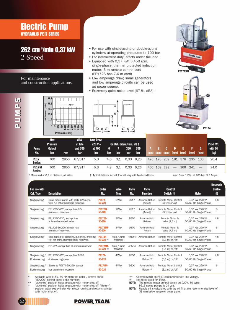
PU
MP
SP
UM
PS
Electric PumpHYDRAULIC PE17 SERIES
262 cm 3/min 0,37 kW2 Speed
For maintenance and construction applications.
• For use with single-acting or double-acting cylinders at operating pressures to 700 bar.
• For intermittent duty; starts under full load.• Equipped with 0,37 KW, 3,450 rpm,
single-phase, thermal protected induction motor; 3 m remote control cord (PE172S has 7,6 m cord)
• Low amperage draw; small generators and low amperage circuits can be used as power source.
• Extremely quiet noise level (67-81 dBA).
PE174
PE172SM
73
57
01
40
21
02
80
35
04
90
70
0
6,7
5,3
4,0
2,7
1,3
0
Pressure (bar)
Oil
Volu
me
( l/
min
.)
ReservoirelbasU lortnoC evlaV evlaV evlaV redrOhtiw esu roF
)l(rotoM†† hctiwSnoitcnuF.oNepyT.oNnoitpircseDepyT .lyC
Single-Acting Base model pump with 0,37 KW pump PE172- 2-Way 9517 Advance Return Remote Motor Control 0,37 kW, 220 V* 4,8with 7,6 l thermoplastic reservoir. 50-220 (Auto†) (3,1m) on/off 50/60 Hz, Single Phase
Single-Acting PE172-50-220, except has 9,5 l PE172M- 2-Way 9517 Advance Return Remote Motor Control 0,37 kW, 220 V* 6aluminum reservoir. 50-220 (Auto†) (3,1m) on/off 50/60 Hz, Single Phase
Single-Acting PE172-50-220, except has PE172S- 3-Way 9570 Advance Hold Remote Motor & 0,37 kW, 220 V* 4,8solenoid operated valve. 50-220 Return Valve (7,6 m) 50/60 Hz, Single Phase
Single-Acting PE172S-50-220, except has PE172SM- 3-Way 9570 Advance Hold Remote Motor & 0,37 kW, 220 V* 6aluminum reservoir. 50-220 Return Valve (7,6 m) 50/60 Hz, Single Phase
Single-Acting Best suited for crimping, punching, pressing. PE172A- Auto./Dump 45554 Advance Return Remote Motor Control 0,37 kW, 220 V* 4,8Not for lifting.Thermoplastic reservoir. 50-220 esahP elgniS,zH 06/05ffo/no )m 1,3(dlofinaM
Single-Acting PE172A, except has aluminum reservoir. PE172AM- Auto./Dump 45554 Advance Return Remote Motor Control 0,37 kW, 220 V* 650-220 esahP elgniS,zH 06/05ffo/no )m 1,3(dlofinaM
Single-Acting / PE172-50-220, except has 9500 PE174- 4-Way 9500 Advance Hold Remote Motor Control 0,37 kW, 220 V* 4,8
Double-Acting double-acting valve. 50-220 Return** (3,1 m) on/off 50/60 Hz, Single Phase
Single-Acting / Same as PE174-50-220, except PE174M- 4-Way 9500 Advance Hold Remote Motor Control 0,37 kW, 220 V* 6
Double-Acting has aluminum reservoir. 50-220 Return** (3,1 m) on/off 50/60 Hz, Single Phase
* Available with 115V., 60 Hz motor (to order , remove suffix"50-220" behind pump order number).
** "Advance" position holds pressure with motor shut off.† "Advance" position holds pressure with motor shut off. "Return"
position advances cylinder with motor running and returns cylinderwith motor shut off.
†† Control switch on PE17 series wired with line voltage.Not to be used for lifting.
NOTE: The remote motor control switch on 220V., 50 cyclePE17 series pumps is 24 volt.
NOTE: Usable oil is calculated with the oil fill at the recommended level of 38 mm below reservoir cover plate.
* Measured at 0,9 m distance, all sides. † Typical delivery. Actual flow will vary with field conditions. Amp Draw 115V - at 700 bar: 9.5 Amps.
Max. dBA Amp Draw .tW .dorP† )@ .nim/.sretil( .leD liO– V 022 eldI ta erusserP
Pump Output and 700 at 700 0 7 350 700 A B C D E F G with OilNo. bar rpm bar bar bar bar bar bar (mm) (mm) (mm) (mm) (mm) (mm) (mm) (kg)
PE17 700 2850 67/81* 5.3 4,8 3,1 0,33 0,26 470 178 289 181 378 235 130 20,4SeriesPE17M 700 2850 67/81* 5.3 4,8 3,1 0,33 0,26 460 168 292 — 368 241 — 24,0 Series
52

www.powerteam.com
PU
MP
SP
UM
PS
Ideal for use with small hydraulically powered tools.
295 cm 3/min 0,37 KWVanguard Jr. Series®
Electric PumpHYDRAULIC PE18 SERIES
700 bar
* 9,5 l reservoir.** Measured at 0,9 m distance, all sides.
Amp Draw 115V at 700 bar: 10.2 Amps.
† Typical delivery. Actual flow will vary with field conditions.†† Special application pumps for cutting, crimping or pressing.
Max. dBA Amp Draw.tW .dorP† )@ .nim/.sretil( .leD liOV 022 eldI taerusserP
Pump Output and 700 at 700 0 7 350 700 A B C D F G with OilNo. bar rpm bar bar bar bar bar bar (mm) (mm) (mm) (mm) (mm) (mm) (kg)
PE182 700 12.000 85/90** 6.5 Amp. 3,7 3,0 0,4 0,3 406 121 203 181 152 130 13,6PE183 700 12.000 85/90** 6.5 Amp. 3,7 3,0 0,4 0,3 406 121 203 181 152 130 13,6PE183A 700 12.000 85/90** 6.5 Amp. 3,7 3,0 0,4 0,3 406 121 203 181 152 130 13,6PE184 700 12.000 85/90** 6.5 Amp. 3,7 3,0 0,4 0,3 406 121 203 181 152 130 13,6PE183-2* 700 12.000 85/90** 6.5 Amp. 3,7 3,0 0,4 0,3 470 184 292 254 241 203 19,0PE184-2* 700 12.000 85/90** 6.5 Amp. 3,7 3,0 0,4 0,3 470 184 292 254 241 203 19,0PE183C †† 700 12.000 85/90** 6.5 Amp. 3,7 3,0 0,4 0,3 406 121 203 181 152 130 13,6PE184C †† 700 12.000 85/90** 6.5 Amp. 3,7 3,0 0,4 0,3 406 121 203 181 152 130 13,6
• Vanguard Jr.®pumps provide two-speed high performance in a light-weight, compact package.
• Gauge port provided on pump. Metal reservoir on all models.
• Equipped with a 0,37 KW, 12,000 rpm, 220 volt, 50 Hz single phase universal motor that starts under load,even at reduced voltage.
• Low amperage draw permits use with smaller generators and low amperage circuits.
• All pumps have a 3 m remote control (PE183C has 7,6 m remote control).
• CSA rated for intermittent duty. Noise level of 85-90 dBA.
Pressure (bar)
73
57
0140
210
280
350
420
490
700
5,6
4,6
4,0
3,2
2,4
1,6
0,8
0Oil
Volu
me
(l/m
in.)
PE182
ReservoirelbasU lortnoC evlaV evlaVredrOhtiw esu roF
)l(rotoMhctiwSnoitcnuFepyT.oNnoitpircseDepyT .lyC
Single-Acting Base model pump has 0,37 KW PE182- 2-Way Advance Return† Remote Motor Control 0,37 kW, 220 V** 50/60 Hz, 1,7pump with 2-Way valve and 50-220 (3,1 m) on/off A.C., Single Phase1,9 l reservoir.
Single-Acting PE182-50-220, except PE183- 3-Way Advance Hold Remote Motor Control 0,37 kW, 220 V** 50/60 Hz, 1,7has 3-way valve. 50-220 Return (3,1 m) on/off A.C., Single Phase
Single-Acting PE183-50-220, except PE183-2- 3-Way Advance Hold Remote Control 0,37 kW, 220 V** 50/60 Hz, 8,4††has 9,5 l reservoir. 50-220 Return (3,1 m) A.C., Single Phase
Single-Acting PE183-50-220, except PE183A- Auto./Dump Advance Return Remote 0,37 kW, 220 V** 50/60 Hz, 1,7has "dump valve". 50-220 esahP elgniS,.C.A)m 1,3(pmuP
Single-Acting Special crimping pump. PE183C- Special, for Advance Hold Remote Motor Control 0,37 kW, 220 V** 50/60 Hz, 1,750-220 crimping only Return (7,6 m) on/off A.C., Single Phase
Single-Acting / Base model pump has 0,37 KW PE184- 4-Way Advance Hold Remote Motor Control 0,37 kW, 220 V** 50/60 Hz, 1,7Double-Acting pump for double-acting systems 50-220 Return† (3,1 m) on/off A.C., Single Phase
with 1,9 l reservoir. Single-Acting / PE184, except with PE184-2- 4-Way Advance Hold Remote Motor Control 0,37 kW, 220 V** 50/60 Hz, 8,4††Double-Acting 9,5 l reservoir. 50-220 Return† (3,1 m) on/off A.C., Single PhaseSingle-Acting / Special crimping pump. PE184C- 4-Way Advance Return Remote Control 0,37 kW, 220 V** 50/60 Hz, 1,7Double-Acting 50-220* (3,1 m) on/off A.C., Single Phase
* Also for use with special single-acting cylinder applications.** Available with 115 Volt, 60 Hz motor (to order, remove suffix
"50-220" behind pump order number). Specify voltage when ordering.Universal motor run on 220V/50Hz or 60Hz/Single phase.
† Holds when motor is shut off and valve is in "advance" position.†† Pumps supplied with 7,6 l oil (usable oil is 5,7 l), will hold 9,5 l
when filled to within 13 mm below reservoir cover plate.Not to be used for lifting.
53

PU
MP
SP
UM
PS
Low-speed, high-torque for heavy-duty, extended-cycle operations.
Electric PumpHYDRAULIC PE21 SERIES
361 cm 3/min, 0.75 kWTwo-speed
PE214
PE214S
700 bar
Max. dBA Pressure at Idle Oil Del. (l/min. at.) Prod. Wt.
Pump Output and 700 7 70 350 700 A B C D E F G H J K*** w/OilNo. bar rpm bar bar bar bar bar (mm) (mm) (mm) (mm) (mm) (mm) (mm) (mm) (mm) (in) (kg)
PE21 700 1.437 70* 4,4 0,5 0,4 0,36 543 292 241 165 254 203 359 241 82,6 1/2-20 44,4†Series UNF
* Measured at a 0,9 m distance, all sides.*** For 50,8 mm dia. swivel casters, order (4) No. 10494.
† Shipping weight with manual valve; add 6,4 kg forpump with solenoid valve.
* Manual valve. Pump is equipped with RUN/OFF/PULSE switch for control of motor.† 24V Solenoid valve. Pump is equipped with a remote control switch with 3,1 m cord.††For single-acting operation, off the electric motor when manual valve in “Retract” position.
riovreseR warD pmA .xaMelbasU 007 ta evlaV evlaV evlaV redrOhtiw esu roF
Cyl. Type Description No. Type No. Function bar Motor (l)
Single-Acting 0,75 KW pump with PE213- 7.9tloV 022,WK 57,0dloH ecnavdA*0259yaW-39,5 l Reservoir and 50-220 Return 230 V - 9.5 amps 50 Hz, Single Phasemanual valve.
Single-Acting PE213, except has PE213S- 3-Way 9599† 7.9tloV 022,WK 57,0 dloH ecnavdAsolenoid operated 50-220 Return 230 V - 9.5 amps 50 Hz, Single Phaseremote valve.
††Single-Acting/ 0,75 KW pump with PE214- 7.9tloV 022,WK 57,0dloH ecnavdA*6059yaW-4Double-Acting 9,5 l Reservoir and 50-220 Return 230 V - 9.5 amps 50 Hz, Single Phase
manual valve.
Double-Acting PE214, except has PE214S- 4-Way 9512† 7.9 tloV 022,WK 57,0dloH ecnavdAsolenoid operated 50-220 Return 230 V - 9.5 amps 50 Hz, Single Phaseremote valve.
• Totally enclosed, fan cooled induction motor: 0,75 KW, 1,725 rpm, 50 Hz, single phase. Thermal overload protection.
• Remote control, with 3,1 m cord is standard on pumps with solenoid valves. Manual valve pumps have "Stop","Start" and "Run/Off/Pulse" switches. Pump controls are moisture and dust resistant.
• Motor drip cover with carrying handles and lifting lug.
• Low noise level of 70 dBA@ 700 bar.• In the event of electrical interruption,
pump shuts off and will not start up until operator presses the pump start button.
• 24 volt control circuits on units with remote controls provide additional user/operator safety.
Pressure (psi)
Oil
Volu
me
(lit
ers/
min
.)
Available with 115 volt, 60Hz motor (to order, remove suffix “50-220” behind pump order number)
Amp Draw 115V at 700 bar: 19 Amps.For 230V, 60Hz motor (change suffix to "-230")
54

www.powerteam.com
0,48 I/min.Two-SpeedVanguard® Series
Electric PumpHYDRAULIC PE30 SERIES
55
PU
MP
SP
UM
PS
• Deliver a powerful punch to operate single-acting or double-acting cylinders.• Integral roll cage protects pump from abuse.• 0,75Kw (1 hp), single phase, permanent magnet motor.• High performance to weight ratio.• Starts under full load even when voltage is reduced to 50% of nominal rating.• Quiet operation: 87 dBA @ 700 bar and 82 dBA @ 0 bar. CSA rated for intermittent duty.• Remote controls and/or solenoid valves feature 24 volt controls.
Ideas for maintenance and construction applications
Pressure (bar)
35
70
140
210
280
350
420
490
560
700
10,7
9,3
8,0
6,7
5,3
4,0
2,7
1,3
0
Oil
Vol
ume
(l/m
in.)
Max Noise Amp.Draw Pressure level 220V at .tW .dorP )..ta nim/l ( .leD liO Output at 700 bar 700 bar 7 35 70 350 700 Overall Dimensions With Oil
)gk( )mm( rab rab rab rab rab )A( )ABd( rab .oN pmuP
PE30 Series 700 87/82 7 4,8 3,2 0,7 0,6 0,5 254L x 229W x 406H 18,6 with 4,7 l res. PE30 Series 700 87/82 7 4,8 3,2 0,7 0,6 0,5 343L x 241W x 419H 22,2 with 7,6 l res.
H
W L
riovreseR
* “Posi-Check®” valve design, “Posi-Check®” guards against pressure loss when valve is shifted from “advance” to “hold” position. ** Shipped with 3,8 l of oil (3,4 l usable).*** Shipped with 7,6 l of oil.
Not to be used for lifting. Best suited for crimping, pressing & punching applications.
elbasU rotoM lortnoC evlaV evlaV evlaV redrO htiw esu roF Cyl.-type Description No. Type No. Function Switch (4.000 rpm) (l)
Single-act. Base model 0,75 KW pump PE302- 3-Way, Hold On/Off/ 0,75 KW 220/230 VAC, with 4,7 l Reservoir & 220 2 Pos. 9584 Advance Return Pulse Switch 50 Hz, Single Phase 4,5**
.evlav noitisop 2
Single-act. PE302-220, except PE302-2- 3-Way, Hold On/Off/ 0,75 KW 220/230 VAC, has 6,6 l reservoir. 220 2 Pos. 9584 Advance Return Pulse Switch 50 Hz, Single Phase 6,1***
Single-act. PE302-220, except has PE302R- 3-Way, Hold Remote Motor 0,75 KW 220/230 VAC, remote motor control. 220 2 Pos. 9584 Advance Return Control (3,1 m) 50 Hz, Single Phase 4,5**
Single-act. PE302R-220, except PE302R-2- 3-Way, Hold Remote Motor 0,75 KW 220/230 VAC, has 6,6 l reservoir. 220 2 Pos. 9584 Advance Return Control (3,1 m) 50 Hz, Single Phase 6,1***
Single-act. PE302R-220, except also PE302S- 3-Way, Hold Remote Motor & 0,75 KW 220/230 VAC, has solenoid operated 220 2 Pos. 9570 Advance Return Valve (3,1 m) 50 Hz, Single Phase 4,5** remote valve.
Single-act. PE302S-220, except PE302S-2- 3-Way, Hold Remote Motor & 0,75 KW 220/230 VAC, has 6,6 l reservoir. 220 2 Pos. 9570 Advance Return Valve (3,1 m) 50 Hz, Single Phase 6,1***
Single-act. PE302-220, except PE302A- Auto Dump Automatic Pilot Remote Motor 0,75 KW 220/230 VAC, has “Auto Dump” valve 220 9610 Operation Control (3,1 m) 50 Hz, Single Phase 4,5**
Single-act. Base model 0,75 KW pump PE303- 3-Way, Advance Hold On/Off/ 0,75 KW 220/230 VAC, with 4,7 l Reservoir & 220 3 Pos. 9520* Return Pulse Switch 50 Hz, Single Phase 4,5** 3 position valve.
Single-act. PE303-220, except PE303-2- 3-Way, Advance Hold On/Off/ 0,75 KW 220/230 VAC, has 6,6 l reservoir. 220 3 Pos. 9520* Return Pulse Switch 50 Hz, Single Phase 6,1***
Single-act. PE303-220, except PE303R- 3-Way, Advance Hold Remote Motor 0,75 KW 220/230 VAC, has remote motor control. 220 3 Pos. 9520* Return Control (3,1 m) 50 Hz, Single Phase 4,5**
Single-act. PE303R, except PE303R-2- 3-Way, Advance Hold Remote Motor 0,75 KW 220/230 VAC, has 6,6 l reservoir. 220 3 Pos. 9520* Return Control (3,1 m) 50 Hz, Single Phase 6,1***
Double-act. Base model 0,75 KW pump PE304- 4-Way, 3 Pos. 9506* Advance Hold On/Off/ 0,75 KW 220/230 VAC, with 4,7 l Reservoir & 220 Tandem Ctr. Return Pulse Switch 50 Hz, Single Phase 4,5** 4-way valve for double-acting systems
Double-act. PE304-220, except PE304-2- 4-Way, 3 Pos. 9506* Advance Hold On/Off/ 0,75 KW 220/230 VAC, has 6,6 l reservoir. 220 Tandem Ctr. Return Pulse Switch 50 Hz, Single Phase 6,1***
Double-act. PE304-220, except PE304R- 4-Way, 3 Pos. 9506* Advance Hold Remote Motor 0,75 KW 220/230 VAC, has remote motor control. 220 Tandem Ctr. Return Control (3,1 m) 50 Hz, Single Phase 4,5**
Double-act. PE304R-220, except PE304R-2- 4-Way, 3 Pos. 9506* Advance Hold Remote Motor 0,75 KW 220/230 VAC, has 6,6 l reservoir. 220 Tandem Ctr. Return Control (3,1 m) 50 Hz, Single Phase 6,1***
PE302SPE302
700 bar

IntensifierHYDRAULIC
Order Page *Cylinder
56
Converts low-pressure portablehydraulic pumps or on-boardhydraulic systems, into highpressure power sources.
Pressure ratio 5:1
PU
MP
SP
UM
PS
700 bar
• Applications include utilities, railroads, construction, riggers and others.• Operates single- or double-acting cylinders, jacks, and tools such as crimpers, spreaders, cable cutters, or tire tools.• May be used to operate two separate, single-acting tools (with integral valves)
independently, without need for additional manifold.• Compact and rugged for use inside a utility vehicle aerial bucket or stowing in
a vehicle.• Control valve included. Other Power Team
valves available as an option to suit your specific application, if needed; consult factory.• No reservoir level to maintain; uses low
pressure system as oil supply.• Has 3⁄8” NPTF ports; compatible with standard fittings for low and high pressure systems.
HB443
wolF tuptuO wolF tupnI wolF tupnI wolF tuptuO
egnaR erusserP egnaR evlaV evlaV evlaV redrO htiw esu roF Cyl. Type Description No. Type No. Function (l/min) (bar) (l/min) Single-Acting Hydraulic intensifier for HB443 3-Way 9520* Advance Hold 0 -38 20 - 138 0 - 9,5 single-acting systems 3-Position Return Single-Acting/ Hydraulic intensifier for HB444 4-Way 9506* Advance Hold 0 -38 20 - 138 0 - 9,5 Double-Acting double-acting systems 3-Position Return Double-Acting Hydraulic intensifier for HB445-RR 4-Way – Advance Hold 0 -38 20 - 138 0 - 9,5 double-acting torque 3-Position Return wrench tools
Output Flow Pump at 700 A B C D E F Prod. Wt. No. bar (mm) (mm) (mm) (mm) (mm) (mm) (kg)
HB44- 0,7 l/min. 210 368 156 70 114 267 7,2 Series
A
B
DE
WA
RN
ING
C
F
† For maximum efficiency, recommended input flow is 19 l/min at a maximum pressure of 140 bar. Higher flows and/or pressures must be compensated for at the system pump (e.g., relief valve, variable flow devices, etc.).
* Posi-Check®” valve design, “Posi-Check®” guards against pressure loss when valve is shifted from “advance” position to “hold” position.

www.powerteam.com
PU
MP
SP
UM
PS
Best suited for under the roof maintenance and production applications.
0,75/min - 1,12 kWTwo-speed
Electric PumpHYDRAULIC PE46 SERIES
• Two-speed high performance pump.• For use with single- or double-acting
cylinders at operating pressures to 700 bar.
• Equipped with a 1.12 KW, 3,450 rpm single-phase, 50 Hz thermal protected induction motor that starts under full load. Noise level of 77-81 dBA.
• All equipped with a 3,1 m remote control except PE462S which has a 7,6 m remote control.
• 24 volt control circuit on all units with remote control.
• CSA rated for intermittent duty.
PE464
PE462S
Pressure (bar)
7
35
70
14
0
21
0
280
350
490
700
6,7
5,3
4,0
2,7
1,3
0Oil
Volu
me
(l/
min
.)
ReservoirelbasU lortnoCevlaV evlaV evlaV redrOhtiw esu roF ***
hctiwSnoitcnuF.oNepyT.oNnoitpircseDepyT .lyC ††† Motor (l)
Single-Acting Base model 1,12 KW pump with PE462- 3-Way 9584 Advance Remote Motor Control 1,12 KW, 220 VAC* 9,79,5 l metal reservoir. 50-220 Return† (3,1 m) on/off 50 Hz, Single Phase
Single-Acting PE462-50- 220, except has solenoid valve. PE462S- 3-Way 9570 Advance Remote Motor/ 1,12 KW, 220 VAC* 9,750-220 Return** Valve (7,6 m) 50 Hz, Single Phase
Single-Acting PE462-50-220, except has "dump valve" PE462A- Auto/Dump 9610 Advance Remote Motor Control 1,12 KW, 220 VAC* 9,750-220 3-Way Return (3,1 m) on/off 50 Hz, Single Phase
††Single-Acting/ PE462-50-220, except has PE464- 4-Way 9500 Advance Hold Remote Motor Control 1,12 KW, 220 VAC* 9,7Double-Acting 9500 double-acting valve. 50-220 Return† (3,1 m) on/off 50 Hz, Single Phase
Double-Acting PE462S-50-220, except PE464S- 3/4-Way 9552 Advance Remote Motor/ 1,12 KW, 220 VAC* 9,7has 9592 double-acting valve. 50-220 Return** Valve (3,1m) 50 Hz, Single Phase
* Available with 115 V., 60 Hz motor (to order, remove suffix"50-220" behind pump order number). Specify voltage when ordering.
** "Advance" position holds pressure with motor shut off.*** Usable oil is calculated with the oil fill at the recommended level
of 13 mm below reservoir cover plate.
† "Advance" position holds pressure with motor shut off."Return" position returns cylinder.
†† For single-acting operation, off the electric motor when manual valve in “Retract” position.
††† The remote motor control switch on PE46 series pumps is 24 volt.
Not to be used for lifting. When pump is shut off, oil returns to reservoir.
Max. Noise level Amp Draw.tW .dorP†)..ta .nim/l( .leD liO- V 022 eldI taerusserP
Pump Output and 700 bar at 700 bar 0 7 350 700 A B C D E F G w/OilNo. bar rpm (dBA) (A) bar bar bar bar (mm) (mm) (mm) (mm) (mm) (mm) (mm) (kg)
PE46-Series 700 2.875 77/81 11.6 8,2 7,4 0,8 0,75 499 173 292 254 378 241 203 35,8PE46-220 700 2.875 77/81* 11.6 8,2 7,4 0,8 0,75 499 173 292 254 378 241 203 41,3
* Measured at 0,9 m distance, all sides. † Typical delivery. Actual flow will vary with field conditions.
Amp Draw 115V at 700 bar: 25 Amps.
For 230V, 60 Hz motor (to order, change suffix to "-230" behind pump order number
57

PU
MP
SP
UM
PS
Heavy duty multiple-applicationspump. Heavy construction and concrete stressing. Low voltagestarting possible.
0,92 l/min - 0,84 kW
Electric PumpHYDRAULIC PE55 VANGUARD ® • 0,84 KW, 12,000 rpm, 220 volt, 50 Hz universal motor; draws 15 amps
at full load, starts at reduced voltage. CSA rated for intermittent duty.• 3,1 m remote motor control
(except PE552S which has a 7,6 m remote motor and valve control).• True unloading valve achieves greater pump efficiency, allowing higher flows
at maximum pressure.• Reservoirs available in sizes up to 38 liters. Consult factory.• Light weight and portable. Best weight to performance ratio of all Power Team pumps.• "Assemble to Order" System: There are times when a custom pump is required.
Power Team’s "Assemble to Order" system allows you to choose from a wide range of pre-engineered, off-the-shelf components to build a customized pump to fit specific requirements. By selecting standard components you get a "customized" pump without "customized" prices. All pumps come fully assembled, less oil and ready for work.
PE55TWPTorque Wrench
4 mounting holes 1⁄2"–20
Max. Noise level Amp Draw .tW .dorP)..ta nim/l( .leD liO rab 007 tadna eldIerusserP
Pump Output at 700 bar (220 V.) 0 50 350 700 A B C D E F G w/OilNo. bar rpm (dBA) (A) bar bar bar bar (mm) (mm) (mm) (mm) (mm) (mm) (mm) (kg)
PE55-Series 700 12,000 90/89* 15 11,5 7,2 1,2 0,92 464 292 241 178 254 203 356 29,4PE55-220 193025
*Noise level reading (dBA) measured at a 0,9 m distance, all sides. Amp draw at 700 bar, 115 volts 60 Hz is 25 Amps.
Pressure (bar)
35
70
14
0
21
0
28
0
35
0
42
0
49
0
56
0
70
0
12,8
11,2
9,6
8,0
6,4
4,8
3,2
1,6
0Oil
Volu
me
(l/m
in.)
PE554WWeather-resistant pump
58
Applications
PE554Heavy duty pump
700 bar

www.powerteam.com
PU
MP
SP
UM
PS
Heavy duty multiple-applicationspump. Heavy construction and concrete stressing. Low voltagestarting possible.
0,92 l/min - 0,84 kW
Electric PumpHYDRAULIC PE55 VANGUARD®
PE554PT PE552PE554S
700 bar
* Pumps available with 115 volt, 60 Hz motors. (to order removethe –50-220 suffix from the order code).
** Holds with motor shut off.*** To order PE55 series pumps with CSA approval, add "–C" to
the Order No.† Valves have "Posi-Check®" feature.
Universal motor run on 220V/50Hz or 60Hz/Single phase.
†† Control switch wired with line voltage. All remotes are 3,1m longexcept for PE552S which is 7,6m long.
††† Valving allows alternate and independent operation of two differentspring return tools. Valve holds pressure only while valve is in "A"or "B" port position with pump motor shut off.
Not to be used for lifting.
Reservoir elbasU lortnoC evlaVevlaV evlaV redrOhtiw esu roF
)l(rotoM†† hctiwSnoitcnuF.oNepyT***.oNnoitpircseDepyT .lyC
Single-Acting Base model 0,84 KW pump with 9,5 l reservoir, PE552- 3-Way 9582 Advance Remote 0,84 KW*, 220 VAC 8,6remote motor control & 3-way valve. 50-220 Return** Motor 50Hz, Single Phase
Single-Acting PE552-50-220, except also has solenoid PE552S- 3-Way 9570 Advance Hold Remote Motor 0,84 KW*, 220 VAC 8,6operated remote valve. 50-220 Return & Valve 50Hz, Single Phase
Single-Acting PE552-50-220, except has "Auto Dump" valve. PE552A- Auto/Dump 9610 Advance Remote 0,84 KW*, 220 VAC 8,650-220 Return Motor 50Hz, Single Phase
Single-Acting 0,84 KW pump with 9,5 l reservoir. PE553- 3-Way† 9520 Advance Hold Remote 0,84 KW*, 220 VAC 8,6Valve has "Posi-check" feature. 50-220 Return Motor 50Hz, Single Phase
Single-Acting/ Base model 0,84 KW pump with 9,5 l res. PE554- 4-Way† 9506 Advance Hold Remote 0,84 KW*, 220 VAC 8,6Double-Acting and 4-way valve for double-acting systems. 50-220 Return Motor 50Hz, Single Phase
Single-Acting/ PE554-50-220, except has PE554T- 4-Way 9500 Advance Hold Remote 0,84 KW*, 220 VAC 8,6Double-Acting 9500 tandem center valve. 50-22.0 Return Motor 50Hz, Single Phase
Single-Acting/ For use with single-acting Spring Seat, PE554P- 4-Way 9500 Advance Hold Remote 0,84 KW*, 220 VAC 8,6Double-Acting Stressing Jack or double-acting cylinder. 50-220 Return Motor 50Hz, Single Phase
Double-Acting For use with single- or double-acting Power Seat, PE554PT- 4-Way 9628 Advance Hold Remote 0,84 KW*, 220 VAC 8,6Stressing Jacks ONLY. 50-220 Sequenced Motor 50Hz, Single Phase
Return
Double-Acting Pump suitable to run multiple . PE554C- 4-Way 9511††† Advance Hold Remote 0,84 KW*, 220 VAC 8,6spring return tools 50-220 Return Motor 50Hz, Single Phase
Double-Acting Pump equipped with 3/4-way solenoid valve. PE554S- 3/4-Way 9552 Advance Hold Remote Motor 0,84 KW*, 220 VAC 8,650-220 Return & Valve 50Hz, Single Phase
Single-Acting/ Same as PE554-50-220, except with weather PE554W- 4-Way† 9506 Advance Hold Remote 0,84 KW*, 220 VAC 8,6Double-Acting protection enclosure 50-220 Return Motor 50Hz, Single Phase
59
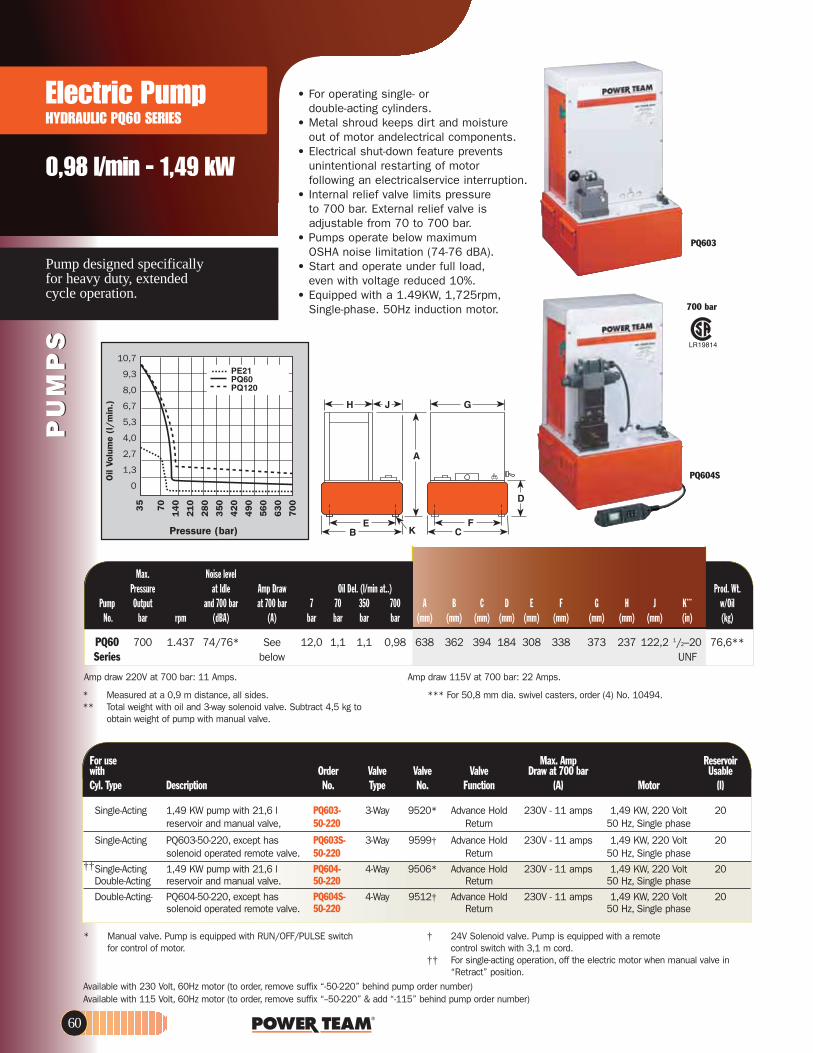
Electric Pump HYDRAULIC PQ60 SERIES
0,98 l/min - 1,49 kW
Pump designed specifically for heavy duty, extended cycle operation.
PU
MP
SP
UM
PS
PQ604S
PQ603
700 bar
For use riovreseR pmA .xaMelbasU rab 007 ta warDevlaVevlaVevlaVredrO htiw
)l(rotoM)A(noitcnuF.oNepyT.oNnoitpircseDepyT .lyC
Single-Acting 1,49 KW pump with 21,6 l PQ603- 3-Way 9520* Advance Hold 230V - 11 amps 1,49 KW, 220 Volt 20reservoir and manual valve, 50-220 esahp elgniS,zH 05nruteR
Single-Acting PQ603-50-220, except has PQ603S- 3-Way 9599† Advance Hold 230V - 11 amps 1,49 KW, 220 Volt 20solenoid operated remote valve. 50-220 esahp elgniS,zH 05nruteR
††Single-Acting 1,49 KW pump with 21,6 l PQ604- 4-Way 9506* Advance Hold 230V - 11 amps 1,49 KW, 220 Volt 20Double-Acting reservoir and manual valve. 50-220 esahp elgniS,zH 05nruteR
Double-Acting- PQ604-50-220, except has PQ604S- 4-Way 9512† Advance Hold 230V - 11 amps 1,49 KW, 220 Volt 20solenoid operated remote valve. 50-220 esahp elgniS,zH 05nruteR
* Manual valve. Pump is equipped with RUN/OFF/PULSE switchfor control of motor.
† 24V Solenoid valve. Pump is equipped with a remote control switch with 3,1 m cord.
†† For single-acting operation, off the electric motor when manual valve in “Retract” position.
Max. Noise levelPressure at Idle Amp Draw Oil Del. (l/min at..) Prod. Wt.
Pump Output and 700 bar at 700 bar 7 70 350 700 A B C D E F G H J K*** w/OilNo. bar rpm (dBA) (A) bar bar bar bar (mm) (mm) (mm) (mm) (mm) (mm) (mm) (mm) (mm) (in) (kg)
PQ60 700 1.437 74/76* See 12,0 1,1 1,1 0,98 638 362 394 184 308 338 373 237 122,2 1/2–20 76,6**Series below UNF
* Measured at a 0,9 m distance, all sides.** Total weight with oil and 3-way solenoid valve. Subtract 4,5 kg to
obtain weight of pump with manual valve.
*** For 50,8 mm dia. swivel casters, order (4) No. 10494.
• For operating single- ordouble-acting cylinders.
• Metal shroud keeps dirt and moisture out of motor andelectrical components.
• Electrical shut-down feature prevents unintentional restarting of motor following an electricalservice interruption.
• Internal relief valve limits pressureto 700 bar. External relief valve isadjustable from 70 to 700 bar.
• Pumps operate below maximumOSHA noise limitation (74-76 dBA).
• Start and operate under full load,even with voltage reduced 10%.
• Equipped with a 1.49KW, 1,725rpm,Single-phase. 50Hz induction motor.
10,7
9,3
8,0
6,7
5,3
4,0
2,7
1,3
0
Pressure (bar)
35
70
14
0
21
0
28
0
35
0
42
0
49
0
56
0
63
0
70
0
Oil
Volu
me
(l/
min
.)
.spmA 22 :rab 007 ta V511 ward pmA.spmA 11 :rab 007 ta V022 ward pmA
Available with 230 Volt, 60Hz motor (to order, remove suffix “-50-220” behind pump order number)Available with 115 Volt, 60Hz motor (to order, remove suffix “--50-220” & add “-115” behind pump order number)
60

www.powerteam.com
PU
MP
SP
UM
PS
Low speed, high torque pumpdesigned specifically for heavy duty,extended cycle operation. Ideal for press operation.
2,0 l/min - 2,24 kW
Electric Pump HYDRAULIC PQ120 SERIES
• Start and operate under full load,even with voltage reduced 10%.
• Electrical shut-down feature prevents unintentional restarting of motor following an electrical service interruption.
• Internal relief valve limits pressure to 700 bar. External relief valve is adjustable from 70 to 700 bar.
• Pump prewired at factory with a 2,24 KW,1,725rpm 380 volt, 50 Hz. 3 Phase induction motor. Other electrical configurations are available. See ordering information below.
• 24 volt control circuits on units with remote controls for added user/operator safety.
• 2,24 KW(3 phase) motor with thermal overload protection. Motor starter and heater element supplied as standard equipment; no hidden charges!
• Metal shroud keeps dirt and moistureout of motor and electrical components.
• Pumps operate below maximum OSHA noise limitation.
PQ1204S
PQ1203
700 bar
10,7
9,3
8,0
6,7
5,3
4,0
2,7
1,3
0
Pressure (bar)
35 70 140
210
280
350
420
490
560
630
700
Oil
Volu
me
(l/
min
.)
Max. Noise levelPressure at Idle Amp Draw Oil Del. (l/min at..) Prod. Wt.
Pump Output and 700 bar at 700 bar 7 70 350 700 A B C D E F G H J K*** w/Oil No. bar rpm (dBA) (A) bar bar bar bar (mm) (mm) (mm) (mm) (mm) (mm) (mm) (mm) (mm) (in) (kg)
PQ120- 700 1.437 73/78* See 12,0 2,6 2,1 2,0 638 362 394 184 308 338 373 237 122,2 1/2–20 74,3**Series below UNF
* Measured at a 0,9 m distance, all sides.** Total weight with oil and 3-way solenoid valve.
Subtract 4,5 kg to obtain weight of pump with manual valve.
*** For 50,8 mm dia. swivel casters, order (4) No. 10494.
Amp draw 230V at 700 bar: 10.5 Amps.Amp draw 460V at 700 bar: 5.3 Amps.
ReservoirelbasUevlaVevlaVevlaVredrOhtiw esu roF
)l(rotoMnoitcnuF.oNepyT.oNnoitpircseDepyT .lyC
Single-Acting 2,24 KW pump with 21,6 l PQ1203- 3-Way 9520* Advance Hold 2,24 KW, 380 Volt 20reservoir and manual valve. 50-380 Return 50 Hz, 3 Phase
Single-Acting PQ1203-50-380, except has PQ1203S- 3-Way 9599† Advance Hold 2,24 KW, 380 Volt 20solenoid operated remote valve. 50-380 Return 50 Hz, 3 Phase
†† Single-Acting/ 2,24 KW pump with 21,6 l PQ1204- 4-Way 9506* Advance Hold 2,24 KW, 380 Volt 20Double-Acting reservoir and manual valve. 50-380 Return 50 Hz, 3 Phase
Double-Acting PQ1204-50-380, except has PQ1204S- 4-Way 9512† Advance Hold 2,24 KW, 380 Volt 20solenoid operated remote valve. 50-380 Return 50 Hz, 3 Phase
Available with 460 Volt, 60Hz, 3 phase motors (to order, remove suffix “50-380” behind pump order number), suitable for 440V, 50Hz, 3 phaseFor 230 Volt, 60Hz, 3 phase motors (to order, change suffix to “-230” behind pump order number)380V/50Hz/3 phase also suitable for 415V/50Hz/3 phase.
* Manual valve. Pump is equipped with RUN/OFF/PULSE switch forcontrol of motor.
† 24V Solenoid valve. Pump is equipped with a remote control switch with 3,1 m cord.
††For single-acting operation, off the electric motor when manual valve in “Retract” position.
61

PU
MP
SP
UM
PS
High tonnage double-acting cylinders, Single or multiple cylinder applications. Up to 1,000 Tons
Electric PumpHYDRAULIC PE400 SERIES
6,9 l/min - 7,46 kW
PE4004S700 bar
ReservoirelbasU evlaVevlaVevlaV redrOhtiw esu roF
rotoMnoitcnuF.oNepyT.oNnoitpircseDepyT .lyC †† (l)
†††Single-Acting/ 7,46 KW pump with 75,5 l PE4004- 4-Way 9506 Advance Hold 7,46 KW, 380 volt 64,4†Double-Acting reservoir and manual valve. 50-380 Return 50 Hz, 3 PhaseDouble-Acting PE4004, except has solenoid PE4004S- 4-Way 9512* Advance Hold 7,46 KW, 380 volt 64,4†
operated remote valve. 50-380 Return 50 Hz, 3 Phase
* Add 127mm and 3,6 kg when casters are mounted. (Units are supplied with four 102 mm dia. swivel casters.)
Max. Noise level E F.tW .dorPretsaC retsaC)..ta nim/l( .leD liOwarD pmA eldI taerusserP
Pump Output and 700 bar at 700 bar 15 90 350 700 A* B C D Mfg. Mfg. w/OilNo. bar rpm (dBA) (A) bar bar bar bar (mm) (mm) (mm) (mm) (mm) (mm) (kg)
PE4004-50-380 700 1.437 73/80 See below 20 19,7 7,4 6,9 924 635 610 540 394 546 223PE4004S-50-380 700 1.437 73/80 20 19,7 7,4 6,9 924 635 610 540 394 546 229
NOTE: Valves for spring return cylinders are available upon request. Consult the factory.
* 24V Solenoid valve with remote control.† Usable oil is calculated with oil fill at recommended level at 57 mm below cover plate.
†† PE400 series also available in 230V, 60Hz and 460V, 60Hz. Please specify when ordering. Example: 460V, 60Hz order PE4004 (also suitable for 440V, 50Hz, 3 phase) or for 230V, 60Hz order PE4004-230.
†††For single-acting operation, off the electric motor when manual valve in “Retract” position.
• Two-speed high output pump delivers up to 20 l/min of oil. • Low noise level of 73-80 dBA.• Integral electrical shut-down feature prevents unintentional restarting of motor
following an electrical service interruption. Over-current protection prevents damage to motor as a result of overheating.
• "Stop" and "Start" control buttons are 24 volt. PE4004 has a 4-way/3-position manual valve. The PE4004S has a 4-way/3-position solenoid valve with a 24 volt remote hand switch.
• External pressure relief valve is adjustable from 100 to 700 bar. • Heavy duty 101,6mm dia. casters assure easy maneuvering.• 75,7 l(64,4 l usable) reservoir has a low oil level sight gauge.• Powered by a dual voltage 7,46 KW, 3 phase, 1,725rpm induction motor.• 3 phase motor has all the electrical components necessary to operate the
pump.The customer has no hidden charges when making purchase.• Deliver 20 l/min. of oil at 15 bar, 6,9 l/min. of oil at 700 bar.
18,7
16,0
13,3
10,7
8,0
5,3
2,7
0
Pressure (bar)
28
56
84
11
2
14
0
21
0
28
0
35
0
42
0
49
0
56
0
70
0
Oil
Volu
me
(l/
min
.)
.spmA 71 :rab 007 ta V064 ward pmA.spmA 43 :rab 007 ta V032 ward pmA
380V/50Hz/3 phase also suitable for 415V/50Hz/3 phase.
62

www.powerteam.com
0,5 - 0,9 l/min 1,49 - 4,5 kwGasoline driven
Gasoline PumpHYDRAULIC PG30/55 SERIES
Gasoline power supply ideal for remote locations.
ReservoirrewopesroHelbasUevlaVevlaVevlaVredrOhtiw esu roF
elcyC)ph()l(noitcnuF.oNepyT.oNnoitpircseDepyT .lyCSingle-Acting 2 hp pump with 7,6 l reservoir PG303 3-Way 9520 Advance Hold 6 2 2
nruteR .evlav gnitca-elgnis dna
Single-Acting 6 hp pump with 21,6 l Reservoir PG553 3-Way 9520 Advance Hold 21,3** 6 4nruteR .evlav gnitca-elgnis dna
Double-Acting PG303, except has PG304 4-Way 9506 Advance Hold 6 2 2nruteR .evlav gnitca-elbuod
Double-Acting PG553, except has PG554 4-Way 9506 Advance Hold 21,3** 6 4nruteR .evlav gnitca-elbuod
• A logical choice at work sites where electricity or compressed air are unavailable. For single-acting or double-acting cylinders at operating pressures to 700 bar.
• All gasoline engine/hydraulic pumps feature "Posi-Check®" valve to guard against pressure loss when valve is shifted from "advance" to "hold".
PG303 and PG304• Powered by a 4-cycle, 2 hp HONDA engine
giving it the lowest weight to horsepower ratio of all gasoline driven pumps. Has an aluminum reservoir with 6 l of usable oil.
• PG30 series pumps are equipped with roll cages to protect pump from damage.
• PG30 series pumps weigh in at only 14,5 kg with oil.
PG553 and PG554• 6 hp Intek "Diamond Edge" 4-cycle, by Briggs
& Stratton 21,3 l reservoir.• Same basic pump as PE55 series electrical
Vanguard®pumps.
PG303
** Usable oil is calculated with oil fill at recommended level at 13 mm below cover plate.
* First stage oil delivery from 0-28 bar at 3,7 l/min minimum.
Max.)...ta nim/l( .leD liOerusserP Prod. Wt.
Pump Output 7 70 350 700 A B C D E F w/OilNo. bar rpm bar bar bar bar (mm) (mm) (mm) (mm) (mm) (mm) (kg)
PG303, PG304 700 6.000 4,5* 0,6 0,6 0,5 378 264 241 406 130 343 14,5PG553, PG554 700 3.600 7,9 1,2 1,1 0,9 559 457 318 219 422 229 54,4
PG553 and PG554
PG303 and PG304
35
70
140
210
280
350
420
490
560
630
700
8,07,26,45,64,84,03,22,41,60,8
0Oil
Volu
me
(l/
min
.)
Pressure (bar)
PG554700 bar
63
PU
MP
SP
UM
PS

64
PU
MP
S
Large reservoir capacity roll cageequipped. PG120 for up to 300 toncylinders. PG400 for up to 1,000ton cylinders.
2,1- 6,6 l/min - 4,1 - 14,9 kwMax.output gasoline powered pumps.
Gasoline PumpPG120-PG400 SERIES
PU
MP
S
S4021GP ,4021GP ,3021GPMH021GP
700 bar
Max. Prod.)...ta nim/l( .leD liOerusserP Wt.
Pump Output 7 70 350 700 A B C D E F w/Oil No. bar rpm bar bar bar bar (mm) (mm) (mm) (mm) (mm) (mm) (kg)
PG120HM 700 3,600 7,9 2,8 2,4 2,1 584 394 362 483 338 308 68PG1203 700 3,600 7,9 2,8 2,4 2,1 708 514 362 667 343 464 70PG1204 700 3,600 7,9 2,8 2,4 2,1 708 514 362 667 343 464 70PG1204S 700 3,600 7,9 2,8 2,4 2,1 708 514 362 667 343 464 73PG1200M-4 700 3,600 7,9 2,8 2,4 2,1 1070 457 635 1080 667 184 118PG1200M-4D 700 3,600 7,9 2,8 2,4 2,1 1070 457 635 1080 667 184 127PG4004 700 3,600 20,3 18,4 7,8 6,6 1276 1321 1321 — — — 197PG4004S 700 3,600 20,3 18,4 7,8 6,6 1276 1321 1321 — — — 200
PG4004 and PG4004SPG1200M-4 and PG1200M-4D
• Two-speed high performance pumps ideal for construction, structure moving and rigging applications.
• A logical choice at work sites where electricity or compressed air are unavailable. For single-acting or double-acting cylinders at operating pressures to 700 bar.
• All gasoline engine/hydraulic pumps feature "Posi-Check®" valve to guard against pressure loss when valve is shifted from "advance" to "hold".
• PG1200 Series pumps powered by a Honda 4-cycle, 5.5 hp engine with automatic decompression and electronic ignition. Deliver over 2,1 l/min at 700 bar.
• A 19 liter 5 gallon reservoir means adequate capacity for multi-cylinder applications. Dual element air cleaner protects engine from dusty environments.
• Heavy duty "roll cage" provides pick-up points for lifting. Horizontal bars on PG1203, PG1204 and PG1204S protect unit, provide hand holds for carrying.
• Rubber anti-skid insulation on bottom of reservoir resists skidding and dampens vibration. PG1200M-4 and PG1200M-4D include a pump cart with 305 mm wheels.
• Adjustable external pressure regulator.Pressure (bar)
35
70
14
0
21
0
28
0
35
0
42
0
49
0
56
0
63
0
70
0
23,0
19,7
16,4
13,1
9,8
6,6
3,3
0Oil
Volu
me
(l/m
in.)

www.powerteam.com
PU
MP
SP
UM
PS
PG1204SPG1200M-4D
PG1200M-4• For single-acting cylinders. Has 9520 3-way/3-position
(tandem center) valve, 9596 load lowering valve and 9644 4-port manifold with individual needle valves at each port.
• Has a 9796 coupler and 9797 dust cap at each port. Valving permits precise individual control of up to four cylinders.
• A 9052 heavy duty, fluid filled pressure gauge (0-700 bar) is included.
PG1200M-4D• For single- or double-acting cylinders with precise
individual control of up to four cylinders possible.• Equipped same as PG1200M-4, except has 9506
4-way/3-position (tandem center) valve, and second 4-port manifold without needle valves mounted beneath 9644 manifold for operating double-acting cylinders.
PG400 Series Maximum output Hydraulic Power Package• Ideal for single or multiple cylinder applications.
Has a 4-cycle, 20 hp Honda engine and 76 l reservoir (64,4 l usable) with low oil level sight gauge.
• Steel "roll cage" protects pump, has a lifting hook; 102 mm dia. swivel casters provide mobility.
• Delivers 6,6 l/min of oil at maximum operating pressure.
• Has a 9506 4-way valve. On/off switch and speed control are protected by a panel. Sturdy molded case protects battery (not included).
* Usable oil is calculated with oil fill at recommended levelat 57 mm below cover plate.
** Control up to 4 cylinders independently.*** Has 7,6 m remote control cord.
ReservoirrewopesroHelbasUevlaVevlaVevlaVredrOhtiw esu roF
elcyC)ph()l(noitcnuF.oNepyT.oNnoitpircseDepyT .lyC
Single-Acting Base model 51/2 hp gasoline PG1203 3-Way 9520 Advance Hold 21,3 5.5 4nruteR .riovreser l 22 htiw pmup
Single-Acting PG1203 with cart, rollcage, load PG1200M-4 3-Way 9520 Advance Hold 21,3 5.5 4**nruteR 4469dlofinaMtrop 4,evlav gnirewol
manifold & gauge.Single-Acting/ PG1200M-4D, except without PG120HM 4-Way 9506 Advance Hold 21,3 5.5 4
**nruteR2469dlofinaMrof laedI .trac dna "egaC lloR"gnitcA-elbuoD).son 2(.yrtsudni gnivom esuoh
Double-Acting Base model 51/2 hp gasoline pump, PG1204 4-Way 9506 Advance Hold 21,3 5.5 4nruteRdna riovreser l 22 htiw
double-acting valve.Double-Acting PG1204, except has roll cage, cart, PG1204S 4-Way 9516 Advance Hold 21,3 5.5 4
solenoid valve and 7,6 m cord. Solenoid*** ReturnSingle-Acting/ PG1200M-4, except for PG1200M-4D 4-Way 9506 Advance Hold 21,3 5.5 4
**nruteR4469dlofinaM .smetsys gnitca-elbuodgnitcA-elbuoDDouble-Acting Base model 20 hp pump PG4004 4-Way 9506 Advance Hold 64,4* 20 4
nruteR.riovreser l 67 htiwDouble-Acting PG4004, except has solenoid PG4004S 4-Way 9516 Advance Hold 64,4* 20 4
nruteR***dioneloS.evlav etomer detarepo
65

Hydraulic PumpACCESSORIES
PU
MP
SP
UM
PS
25017202777202778304718
203225
309652309653
251660
20959317627216209
10461
ON/OFF MOTOR CONTROLThe following remote control switches will give you momentary "ON"control of your hydraulic pump. These switches are deadman type,spring loaded to the "OFF" position. They can be used with any Power Team electric hydraulic pumps.No. 25017 - Remote hand control. Has a push button switch,
with a 3,1 m cord. Wt., 0.4 kg.No. 203225 - Remote hand control. Heavy-duty with single push
button switch in a neoprene housing with 3,1 m cord. Housing seals out dust, lint and liquids (unit is not submersible).Wt., 0,4 kg.
No. 10461 - Remote foot control, with 3,1 m cord. Wt., 1,4 kg.No. 251660 - Remote foot control, with 3,1 m cord.
For use with the PE10 style pumps. Wt., 0,4 kg.
SOLENOID & MOTOR CONTROLFor use on solenoid valves that are used on single-acting cylinders:No. 202777 - Remote hand control. Has rocker style switch that
is momentary advance, spring center hold and detented retract.It comes with a 3,1 m cord, for use with 3-way/2 or 3-position valves. Wt.,0,4 kg. For use on solenoid valves that are used on double-acting cylinders:
No. 202778 - Remote hand control. Has rocker style switch that is momentary advance, spring center hold and momentary retract. It comes with a 3,1 m cord, for use with 4-way/3-position valves. Wt., 0,4 kg
No. 309653 – Remote foot control. Can be used in place of either of the above hand controls to control the same type of valves. The switch is momentary on both the advance and retract position and is spring centered to the hold position. This foot switch comes with 3,1 m cord. Wt., 1,8 kg.
No. 17627 – Remote foot control. Same as the No. 309653 but without a cord. Wt., 0,9 kg.
No. 304718 - Remote hand control. Has a rocker style switch that is momentary advance, spring center hold and momentary retract. The switch is wired to start and stop the motor when the valve is energized. It comes with a 3,1 m cord. To be used with 4-way/2-position valves. Wt., 0.4 kg.
No. 309652 – Remote foot control. Has same functions as No. 304718. Supplied with a 3,1 m cord. To be used with 4-way/2-position valves. Wt., 1,8 kg.
No. 216209 – Remote foot control. Same as the No. 309652,but without a cord. Wt., 0,9 kg.
NOTE: See valves listing to determine which remote to use (See page 30-33).
REMOTE AIR MOTOR CONTROLSThis remote hand control has two momentary push buttons,one for advance and one for retract with spring offset to hold. To be used with 4-way/2-position air pilot valves. No. 209593 – Remote hand control with 3,7 m cord. Wt., 0,9 kg.
66

PU
MP
SP
UM
PS
www.powerteam.com
95109515
9620
96419643
9625
SUBPLATESFor remote mounting of control valves. They convert pump mountedvalves to remote mounted valves quickly and easily. No. 9510 - Subplate for remote mounting the following valves; 9500,
9501, 9502, 9504, 9506, 9507, 9511, 9552, 9572, 9575, 9576,9592, 9594 and 9609. Wt., 1 kg 1.5 lbs.
No. 9620 - For use with 9500, 9501, 9502, 9552, 9572, 9592 and 9594. Same as No. 9510 but has integral pressure regulating valve. Wt., 1,7 kg.
PUMP-MOUNTED SUBPLATESWhen fitted between pump cover plate valve mounting flange and controlvalve, provides a separate 3/8" NPTF female port, open to "return" regardless of position of valve. Also provides a separate 3/8" NPTFfemale pressure port. This subplate can be useful when you desire touse one pump with a deck-mounted control valve, plus a separateremote-mounted valve to control another function. For use with the fol-lowing valves: 9500, 9501, 9502, 9504, 9506, 9507, 9511, 9552,9572, 9575, 9576, 9592, 9594 and 9609.No. 9515 - Subplate, Wt., 0,6 kg.No. 9521 - Subplate for use under most pump mounted valves to provide
adjustable pressure control on units not equipped with an external pressure regulator. Wt., 1,7 kg.
PRESSURE SWITCHApplication: Used in a hydraulic circuit where system pressure must
be "held". Automatically (electrically) turns off pump motor when predetermined system pressure is reached. Attaches directly to control valve manifold or can be mounted "in-line" to read system pressure. Has a 1/4" NPTF male thread, and a 1/4" NPTF fitting for gauge mounting if required. Adjustable from 70 to 700 bar. Can also be used to actuate other electrical devices in the system. Wired "normally open" and held closed by spring pressure.
IMPORTANT: Electrical rating of switch is 5 amps at 250 volts max. To prevent permanentdamage to switch, a control relay must be installed to handle currents or voltage exceedingthese limits. Pressure switch should never be used to directly actuate the electrical motor.
No. 9625 - In-line pressure switch with 1/4" NPTF gauge port. Wt., 0,5 kg.
PILOT OPERATED AIR CONTROL VALVESApplication: For use when an air pilot signal is required at a set hydraulic
pressure. Can be used to shift valves, and start or stop pneumatic pumps. Attaches directly to control manifold or can be mounted "in-line" to read system hydraulic pressure. Automatically turns on an air pilot signal when a predetermined system pressure is reached. Has 1/4" NPTF male thread and 1/4" NPTF fitting for gauge mounting if required. Adjustable from 35-700 bar. Maximum rating of 700 l at 7 bar.
No. 9641 - Pilot operated control valve, normally closed, with 1/4" NPTF male thread. Wt., 0,4 kg.
No. 9643 - Same as 9641 except normally open. Wt., 0,4 kg.
9510 and 9620attach to thebottom of valve forremote mounting.The 9515 and 9521mount between thepump cover plateand valve.
Air Out
Air In
Wiring SchematicN.O. Held Closed
White
Black
9521
67

PU
MP
SP
UM
PS
Hydraulic PumpACCESSORIES
68
OIL COOLER KITSNo. 252511 - Oil cooler kit designed for use with PE604T or
PE604PT pumps with 115 VAC. Wt.,2,2Kg.No. 252512 - Oil cooler kit designed for use with PE604T or
PE604PT pumps with 220 VAC. Wt.,2,2 kg.
RESERVOIR BREATHER KITSNo. 206767 - Reservoir breather kit designed for use on PA17,
PA55, PE17, PE55, PE84, PE90, PE120, PG55, PG120, PQ60 and PQ120 series pumps. Wt., 0,6 kg.
No. 250175 - Reservoir breather kit designed for use on PE21 and PE46 series pumps. These kits replace the reservoir filler cap when the pump is used in dusty and dirty environments. Wt., 0,6 kg.
CASTERS 50,8 mm diameter casters attach to the bottom of large
reservoir for portability. Sold individually; order the amount you need.
No. 10494 - Single caster wheel. Wt., 0,1kg.
FLUID LEVEL/TEMPERATURE GAUGE Displays fluid level and temperature of hydraulic oil in
reservoir. 32°-212°F, 0°-100°C. 32 mm wide and 162 mm high.No. 350431 - Fluid level/temperature gauge.
FOOT CONTROL GUARD Guard for use with 10461 and 251660 foot controls. No. 16339 - Wt., 2 kg.
MAGNETIC STRIP Magnetic strip with adhesive back can be added to No.
25017, 202777, 202778 and 304718 hand controls. Provides 2,7 kg. of holding force.
No. 207762 - Wt., 0,1 kg.
300507300472300510300508300690300696300508300693300699
P12P23, P55
P59P157, P159, P300
P157, P159P300
P157D, P159D, P300DP157D, P159D
P300D
AllAllAllABBABB
Order Use Number With Model
16339
Viton* seal kits
207762
350431
206767250175
252511252512
10494
VITON* SEAL KITS Can be used in all “C” and “RH” series cylinders, as well as the P12, P55, P59, P157/P159, P157D/P159D and P300/P300D series of hand pumps. These seals are required when fire resistant hydraulic fluids are used. For use with phosphate ester fluids. Not required with Flame-Out fluid.
* Viton is the E.I. duPont De Nemours & Co., Inc, trade name for flouroelastomers.
VITON* SEAL KITS

PU
MP
SP
UM
PS
www.powerteam.com 69
No. PC200RC - Roll cage for use with PC200. (Cannot be used on pumps with 38 liter reservoirs.) Wt., 16 kg.
No. RC5 - Roll cage. Wt., 9 kg.
UNIVERSAL PUMP CART Mobilize your hydraulic pumps with the PC200. The rugged
tubular frame can easily handle pumps weighing up to 90 kg. With 305 mm wheels, the cart rolls easily. Just load the pump onto the cart and wheel it right to the job. The universal mounting hole pattern lets you handle a wide variety of Power Team pumps.
No. PC200 - Universal pump cart with 305 mm wheels. Cart can be used with the following pumps: PA60, PA64 and PA554 air/hydraulic pumps; PE55 series, PE183-2 and PE184-2 electric/hydraulic pumps; PE21, PQ60 and PQ120 series “Quiet” pumps; PG55 series gas engine/hydraulic pumps; and pumps with optional 19- and 38 l - reservoirs; Nos. RP50, RP51, RP101 and RP103. Wt., 12,3 kg (Shown with pump, pump not included)
PROTECTIVE PUMP ROLL CAGE Safeguards pump, gas engine and valves on the job site.
Horizontal bars provide convenient hand holds for carrying pump, a pick-up point permits lifting unit with an overhead crane or other device. Standard equipment on PG1203 and PG1204. Can be ordered as an option with any other gas, air, or electrically driven hydraulic pump equipped with a 38 l reservoir.
Note: Refer to PG1203/PG1204 specification chart for dimensions of roll cage.
METAL RESERVOIR CONVERSION KITS FOR PUMPS *INCLUDES GASKETS AND FASTENERS.
* Four mounting holes: 1/2”-20, for 50.8 mm diameter swivel casters (No. 10494)** High density polyethylene reservoir. † Aluminum reservoir.
NOTE: All metal reservoirs are equipped with drain plugs and all necessary conversion items. Hydraulic oil is not included with reservoir kits. Please order separately.
C
B A
Usable )mm( eziS esU liO redrO yticapaC
C B A htiW )nim/l( rebmuN )retil(
LARGE CAPACITY RESERVOIRS
7,67,69,59,59,59,51919
37,937,937,937,9
PA6, PA50 series (models A-E)PA6 series (model F), PA 50 series (model F & G)PA6, PA50 series (models A-E)PA6 series (model F), PA50 series (model F & G)PE18 seriesPE55, PE90, PE120, PA55PE55, PE90, PE120, PA55PA46, PE46, PE21PE55, PE90, PE120, PA55PG55, PG120PQ60, PQ120PA46, PE46, PE21
RP20**RP20-F**RP20M*RP20M-F*RP21*RP22†RP50RP51RP100RP101RP103*RP104
7,17,17,27,27,27,118,418,435,135,137,035,1
292292292292292292381381381381392381
241241241241241241318318318318362318
165165165165165165203203356356313356
4,14,14,14,14,1
9,59,59,59,59,5
213895213895213895213895213895
PA174PE172
PE172APE172SPE174
Metal Res. Metal Reservoir Pump Order Reservoir Weight Number Number Capacity (l) (kg)
1,41,41,44,14,1
1,71,71,79,59,5
213896213896213896213895213895
PA50PA50RPA6R
PA50R2PA172
Metal Res. Metal Reservoir Pump Order Reservoir Weight Number Number Capacity (l) (kg)
1,41,41,44,14,1
1,71,71,79,59,5
213896213896213896213895213895
PA6PA6APA6DPA6-2PA6D2
Metal Res. Metal Reservoir Pump Order Reservoir Weight Number Number Capacity (l) (kg)

Valves SELECTION INFORMATION
PU
MP
S/
VA
LVE
SP
UM
PS
/V
ALV
ES
70
Advance/ Posi-Order Page *Cylinder Advance/ Hold Check®
erutaeFnruteRnruteRtloVepyT evlaVnoitarepOnoitacilppA.oN.oN
9500 33 S.A & D.A. Manual 4-way, 3 Pos. Tandem Center — no yes no9501 33 S.A. & D.A. Manual 4-way, 3 Pos. Closed Center — no yes no9502 32 S.A. Manual 3-way, 3 Pos. Closed Ctr. — no yes yes9504 CF S.A. & D.A. Manual 3/4-way, 2 Pos. — yes yes no9506 33 D.A. Manual 4-way, 3 Pos. Tandem Center — no yes yes9507 33 D.A. Manual 4-way, 3 Pos. Closed Center — no yes yes9511 CF S.A. & D.A. Manual 4-way, 3 Pos. Open Center — yes yes no9512 35 D.A. Solenoid 4-way, 3 Pos. Tandem Center 24 no yes yes9513 35 D.A. Solenoid 4-way, 3 Pos. Tandem Center 115 no yes yes9516 35 D.A. Solenoid 4-way, 3 Pos. Tandem Center 12DC no yes yes9517 32 S.A. Manual 2-way, 2 Pos. — no yes no9519 35 D.A. Solenoid 4-way, 3 Pos. Tandem Center 230 no yes yes9520 32 S.A. Manual 4-way, 3 Pos. Tandem Center — no yes yes9522 CF D.A. Solenoid 4-way, 3 Pos. Open Center 230 yes no no9523 CF S.A. Pilot Operated Solenoid 3-way, 2 Pos. 230 yes no no9552 34 S.A. & D.A. Solenoid 3/4-way, 2 Pos. 230 yes no no9553 CF S.A. Pilot Operated Solenoid 3-way, 2 Pos. 24 yes no no9569 34 S.A. Solenoid 3-way, 2 Pos. 24 no yes no9570 34 S.A. Solenoid 3-way, 2 Pos. 230 no yes no9572 34 S.A. & D.A. Solenoid 3/4-way, 2 Pos. 24 yes no no9576 CF S.A. Manual 3-way, 3 Pos. Metering Tandem Ctr. — no yes no9579 34 S.A. Solenoid 3-way, 2 Pos. 115 no yes no9582 32 S.A. Manual 3-way, 2 Pos. — no yes no9584 32 S.A. Manual 3-way, 2 Pos. — no yes no9589 CF S.A. Pilot Operated Solenoid 3-way, 2 Pos. 115 yes no no9590 CF D.A. Solenoid 4-way, 3 Pos. Open Center 115 yes no no9592 34 S.A. & D.A. Solenoid 3/4-way, 2 Pos. 115 yes no no9594 34 S.A. & D.A. Air 3/4-way, 2 Pos. — no yes yes9599 35 S.A. Pilot Operated Solenoid 3-way, 3 Pos. Tandem Center 24 no yes yes9605 CF S.A. Pilot Operated Solenoid 3-way, 3 Pos. Tandem Center 115 no yes yes9609 CF S.A. Manual 3-way, 3 Pos. Tandem Center — no yes no9610 CF S.A. Auto Pilot Operated 3-way, 2 Pos. — yes no no
9610A CF S.A. Manual 2/3-way, 2 Pos. — no yes no9615 CF D.A. Solenoid 4-way, 3 Pos. Open Center 24 yes no no9628 CF S.A. & D.A. Manual Post Tensioning — special no no9632 CF S.A. & D.A. Manual Post Tensioning — special no no
PUMP MOUNTED VALVES
* “S.A.” represents single-acting cylinders, “D.A.” represents double-acting cylindersCF: Consult Factory
Pump Mounted Valves700 bar
Remote Mounted ValvesAvailable: Consult Factory

www.powerteam.com 71
HYDRAULICACCESSORIES
Page
SHUT-OFF VALVES 78-79In-Line
Page
MANIFOLDS 76Standard Blocks Blocks with Valves
Page
700 BAR FITTINGS 80Connectors TeesCouplings SwivelsCrosses Special AdaptersElbows
Page
FLUIDS 77Standard Oil 0,9 l, 3,8 l, 9,5 l, 208 l Flame Out 3,8 l, 9,5 lBio Degradable 3,8 lLow Temperature 3,8 l
Page
GAUGES 74-75Heavy Duty Hydraulic Pressure Gauges Digital and Analog
Page
COUPLERS 73Quick ConnectFlush Face
Page
HOSES 72Rubber Urethane Non-Conducting

72
Hose Burst Order Hose Type Hose I.D. Length Rating No.
Rubber, Wire-braid 6,4 mm 2,4 m 1 400 bar 9757Rubber, Wire-braid 6,4 mm 3,1 m 1 400 bar 9758Rubber, Wire-braid 6,4 mm 3,7 m 1 400 bar 9759Rubber, Wire-braid 6,4 mm 6,1 m 1 400 bar 9760Rubber, Wire-braid 6,4 mm 9,1 m 1 400 bar 9761Rubber, Wire-braid 6,4 mm 15,3 m 1 400 bar 9762Rubber, Wire-braid 9,5 mm High Flow 0,9 m 1 400 bar 9733Rubber, Wire-braid 9,5 mm High Flow 1,8 m 1 400 bar 9776Rubber, Wire-braid 9,5 mm High Flow 3,1 m 1 400 bar 9777Rubber, Wire-braid 9,5 mm High Flow 4,6 m 1 400 bar 9734Rubber, Wire-braid 9,5 mm High Flow 6,1 m 1 400 bar 9778Rubber, Wire-braid 9,5 mm High Flow 9,1 m 1 400 bar 9735Rubber, Wire-braid 9,5 mm High Flow 12,2 m 1 400 bar 9736Rubber, Wire-braid 9,5 mm High Flow 15,3 m 1 400 bar 9779Non-Conductive 6,4 mm 1,8 m 2 800 bar 9773Non-Conductive 6,4 mm 3,1 m 2 800 bar 9774Non-Conductive 6,4 mm 6,1 m 2 800 bar 9775
Hose Burst Order Hose Type Hose I.D. Length Rating No.
Polyurethane 6,4 mm 0,6 m 1 400 bar 9765Polyurethane 6,4 mm 0,9 m 1 400 bar 9766Polyurethane 6,4 mm 1,8 m 1 400 bar 9767Polyurethane 6,4 mm 1,8 m 1 400 bar 9764*Polyurethane 6,4 mm 2,4 m 1 400 bar 9768Polyurethane 6,4 mm 3,1 m 1 400 bar 9769Polyurethane 6,4 mm 3,7 m 1 400 bar 9770Polyurethane 6,4 mm 6,1 m 1 400 bar 9771Polyurethane 6,4 mm 15,3 m 1 400 bar 9772Polyurethane 6,4 mm 22,9 m 1 400 bar 9750Polyurethane 6,4 mm 30,5 1 400 bar 9751Polyurethane 9,5 mm High Flow 1,8 m 2 100 bar 9780Polyurethane 9,5 mm High Flow 3,1 m 2 100 bar 9781Polyurethane 9,5 mm High Flow 6,1 m 2 100 bar 9782Polyurethane 9,5 mm High Flow 15,3 m 2 100 bar 9783
Rubber, Wire-braid 6,4 mm 0,9 m 1 400 bar 9755Rubber, Wire-braid 6,4 mm 1,8 m 1 400 bar 9756Rubber, Wire-braid 6,4 mm 1,8 m 1 400 bar 9754*
No. 9769 No. 97813,1 m Hose 3,1 m Hose
Cylinder 6,4 mm I.D. 9,5 mm I.DC2514C 51 sec. 14 sec.C556C 1 min., 30 sec. 24 sec.C5513C 4 min., 12 sec. 59 sec.C10010C 6 min., 56 sec. 1 min., 3 sec.
CYLINDER RETURN TIME
The figures show the relative effect two styles of hose can haveon return time. Actual times may vary.
Non-conductive hoseFor applications requiring electrical isolationby the hose, non-conductive hose has a leak-age factor of less than 50 microamperes,considered a safe level of conductivity bySAE standards. The covering is polyurethaneand colored orange for easy identification asnon-conductive hose. The covering is not per-forated, preventing moisture from enteringthe hose and affecting its overall conductivi-ty. All non-conductive hoses have a minimumburst pressure of 2800 bar.
Rubber hose 2-ply rated hose reinforced with two braids of high tensile steel wire. The rubber coveringis oil and weather resistant.
Polyurethane hose Made up of nylon core tube with polyesterfiber reinforcement which will withstand theminimum SAE bend radius without shorteningservice life. These hoses last up to seventimes longer than rubber hose, and are suitablefor continuous service at temperaturesfrom -40° to 150° F (-40˚ to 66˚C).
C
B
A
• 3/8" NPTF fittings on both ends.• Operating pressure is 700 bar (10,000psi). All comply with MHI standard IJ100.
HY
DR
AU
LIC
AC
CE
SS
OR
IES
Polyurethane RubberNon-Conductive
HosesH
YD
RA
UL
IC A
CC
ES
SO
RIE
S
NOTE: Polyurethane hoses not recommended for use where heat or weld splatter conditions exist. * Furnished with 9798 hose half coupler and 9800 dust cap.
Hydraulic hose assemblyNo. 9764 – Hose assembly consisting of 9767 (1,8 m hose), 6,4mm I.D.polyurethane with 9798 hose half couplerand 9800 dust cap.No. 9754 – Hose assembly consisting of9756 (1,8 m hose), 6,4 mm I.D. rubber with9798 hose half coupler and 9800 dust cap.
D

www.powerteam.com
Standard & Flush-Face
HY
DR
AU
LIC
AC
CE
SS
OR
IES
HY
DR
AU
LIC
AC
CE
SS
OR
IES
Couplers
9796
9798
97939792
9797 9799
9800
9794 Flush-Face couplers
CYLINDER AND HOSE COUPLERSDesigned for use up to 700 bar with hydraulic jacks,cylinders, etc. They are the threaded union type for interchanging cylinders in seconds. Each half is valvedwith a precision ball for a tight shutoff when disconnected.These couplers also permit the separation of cylinders or hose from pump when at 0 psi with minimal oil loss. No. 9795 – Complete quick coupler, 3/8" NPTF. (Includes two 9800 dust caps.) No. 9798 – Male (hose) half coupler (less hose half dustcap), 3/8" NPTF.No. 9796 – Female (cylinder) half coupler with No. 9800dust cap, 3/8" NPTF. No. 9796-V – Same as 9796, but with Viton seals. No. 9796-E – Same as 9796, but with EPR seals. No. 9799 – Optional metal dust cap (hose half). No. 9797 – Optional metal dust cap (cylinder half).
NO-SPILL, PUSH-TO-CONNECT HYDRAULIC HOSE COUPLERSHigh flow, no-spill, push-to-connect couplers with locking collar and flush face designed for high pressure applications. The flush-face concept makes it easy to clean both coupler ends before connecting. Our uniquepush-to-connect, "dry-break" design eliminates oil spillage.The locking collar makes accidental disconnects a thing ofthe past. For 700 bar operation. Designed to permit high oil flow. No. 9792 – Female (cylinder) half quick coupler only. Wt., 0.1 kg. No. 9793 – Male (hose) half quick coupler only. Wt., 0,1 kg. No. 9794 – Complete quick coupler (male and female). Dustcaps not included. Wt.,0,2 kg.
HYDRAULIC COUPLER DUST CAPDust cap fits either male or female half couplers. No. 9800 – Dust cap. For male or female 3/8" NPTF halfcouplers. Wt., 0,1 kg.
Male coupler9798
Gaugethreads intovalve body.45˚ fitting
needed 9678
Hose threadsdirectly intovalve body.
Air, Electric & Gas Pumps with valve system hook-up
Male coupler9798
Hose canthread directly
into pumpbody
T-adapter9670
GaugeOptional
Single-acting air pump system hook-up
Male coupler9798
Hose canthread directlyinto pump body
T-adapter9670
GaugeOptional
Hand pump system hook-upT-adapter necessary for P12, P19, P23, P59 & P59F pumps.All other hand pumps have a gauge mounting port.
9794 No-Spill HoseCouplers
9795 Cylinder andHose Couplers
73
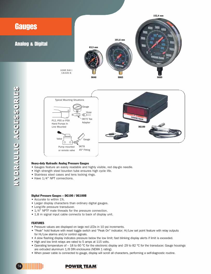
9040
63,5 mm
101,6 mm
152,4 mm
98095609
ASME B40.1GRADE B
DG100
Heavy-duty Hydraulic Analog Pressure Gauges• Gauges feature an easily readable and highly visible, red day-glo needle. • High strength steel bourdon tube ensures high cycle life. • Stainless steel cases and lens locking rings. • Have 1/4" NPT connections.
Digital Pressure Gauges – DG100 / DG100B• Accurate to within 1%. • Larger display characters than ordinary digital gauges. • Long-life pressure transducer. • 1/4" NPTF male threads for the pressure connection. • 1,8 m signal input cable connects to back of display unit.
FEATURES• Pressure values are displayed on large red LEDs in 10 psi increments. • "Peak" hold feature with reset toggle switch and "Peak On" indicator; Hi/Low set point feature with relay outputs
for Hi/Low alarms and/or control signals. • A slow flashing display indicates pressure below the low limit; fast blinking display alerts if limit is exceeded. • High and low limit relays are rated to 5 amps at 115 volts. • Operating temperature of – 18 to 60 °C for the electronic display and -29 to 82 °C for the transducer. Gauge housings
are extruded aluminum 1/8 DIN enclosures (NEMA 1 rating). • When power cable is connected to gauge, display will scroll all characters, performing a self-diagnostic routine.
Typical Mounting Situations
P12, P55 or P59Hand Pumps InLine Mounted
Hose
9670 TeeAdapter
Pump mountedor remote valve
Valve Gauge
967845° Fitting
Gauge
HY
DR
AU
LIC
AC
CE
SS
OR
IES
Analog & Digital
GaugesH
YD
RA
UL
IC A
CC
ES
SO
RIE
S
74

www.powerteam.com
Analog & Digital
HY
DR
AU
LIC
AC
CE
SS
OR
IES
HY
DR
AU
LIC
AC
CE
SS
OR
IES
Gauges
420778
9046
37045
90499048
† The tonnage scale on the gauge is based on a different effective area. A slight error in tonnage reading will occur relative to the different effective area.
STANDARD PRESSURE GAUGE ORDERING INFORMATION
Major Minor Silicone Use With Gauge Face Dia. psi/Bar Tons Graduations Graduations Filled Cylinder Series No.63,5 mm 0-10,000 /.0-690 – 2500 psi, 100 Bar 500 psi, 20 Bar No All 904163,5 mm 0-10,000 /.0-690 – 2500 psi, 100 Bar 500 psi, 20 Bar Yes All 9040100 mm 0-10,000 /.0-690 – 1000 psi, 100 Bar 200 psi, 10 Bar No All 9051100 mm 0-10,000 /.0-690 – 1000 psi, 100 Bar 200 psi, 10 Bar Yes All 9052
no noT 5.,isp 002,5.71-0100 mm 0-10,000 /.0-690 0-30 and 2000 psi, 5 Ton 30, 50 Ton Scales; .2 No RT172, RT302, RT503 9059
elacS noT 5.71 no noT05-0100 mm 0-10,000 /.0-690 0-5 2000 psi, 1 Ton 200 psi, .1 Ton No C & RLS 9053100 mm 0-10,000 /.0-690 0-10 2000 psi, 1 Ton 200 psi, .1 Ton No C, RD, RH, RLS & RSS 9055100 mm 0-10,000 /.0-690 0-25 2000 psi, 5 Ton 200 psi, .5 Ton No C & RD 9063100 mm 0-10,000 /.0-690 0-30 2000 psi, 5 Ton 200 psi, .5 Ton No RH†, RLS & RSS 9065100 mm 0-10,000 /.0-690 0-50 2000 psi, 5 Ton 200 psi, .5 Ton No RH†, RLS & RSS 9067100 mm 0-10,000 /.0-690 0-55 2000 psi, 5 Ton 200 psi, .5 Ton No C, R, RA & RD 9069100 mm 0-10,000 /.0-690 0-60 2000 psi, 5 Ton 200 psi, 1 Ton No RH 9071100 mm 0-10,000 /.0-690 0-100 2000 psi, 10 Ton 200 psi, 1 Ton No C, R, RA, RD, RH, 9075
RLS†, RSS† & RT1004†100 mm 0-10,000 /.0-690 0-150 2000 psi, Initial 200 psi, 2 Ton No C, R, RD & RLS 9077
10 Then 20 Ton100 mm 0-10,000 /.0-690 0-200 2000 psi, 20 Ton 200 psi, 2 Ton No R, RD & RH† 9079
10 Then 20 Ton150 mm 0-10,000 /.0-690 0-690 1000 psi, 100 Bar 100 psi, 10 Bar No All 9089
Digital Pressure GaugeNo. DG100 – Pressure range 0-10.000 psi. No. DG100B – Pressure range 0-700 bar.Note: Serviced only at factory. Wt.,1 kg.
Standard Adapter 115V – For 220V adapter, please request when ordering.
Digital Pressure Gauge AccessoriesNo. 420778 – Gauge stand for DG100. Has angled base mounting to hold gauge
at a convenient viewing angle. Wt., 0,5 kg. No. 37045 – Auxiliary power cord for use with any 12 or 24V battery.
Wt., 0,1 kg. Caution: For use on negative ground systems only.
Standard Analog Pressure Gauge AccessoriesNo. 9046 – Silicone fill kit. 0,2 kg Requires one bottle to fill 100 mm gauge;
four bottles to fill 150 mm gauge. No. 9048 – Replacement lens and pointer for 100mm dia. gauge.
For maximum peak readingNo. 9049 – High performance pulsation dampener.
1/4 " NPTF male x 1/4" NPTF female.
75

HY
DR
AU
LIC
AC
CE
SS
OR
IES
HY
DR
AU
LIC
AC
CE
SS
OR
IES
C
B
B
AB
9642
9691
3/8" NPTF
Ports
9635
21/2" Hex x11/2" Thick
3/8" NPTFPorts
9617
3/8" NPTF
Ports
9648
3/8" NPTF
Ports
9626
3/8" NPTF
Ports
3/8" NPTF
Ports(not shown)
9627
9644
963450,8 mm Square
38,1 mm Thick
3/8" NPTF
Ports
9644
9,5 mm Ø THRU (MOUNTING HOLES)(4 PLACES) (REF.)
9,1 mm(REF.)
25,4 mm(REF.)
152,4 mm(REF.)
3/8" NPTFFEMALE
(6 PLACES)
57,2 mm(REF.)
24,5 mm(REF.)
25,4 mm(REF.)
19 mm(REF.)
19 mm
229 mm(REF.)
152,4 mm76,2 mm
9642
9,1 mm(REF.)
38,1 mm(REF.)
9,5 mm Ø THRU(3 PLACES)(REF.)
3/8" NPTFFEMALE(4 PLACES)
(MOUNTING HOLES)
19 mm(REF.)
87,6 mm(REF.)82,5 mm
(REF.)41,3 mm(REF.)
25,4 mm(REF.)
24,5 mm
14,3 mm
19 mm(REF.)
Manifold A B CNo. (mm) (mm) (mm)
9627 406,4 114,3 38,19648 177,8 38,1 38,1
Remote and Pump Mounted
Manifolds
No. 9691 – "Y" ManifoldExtremely useful when connecting twohydraulic cylinders to a single line. Has three 3/8" NPTF ports. Wt. 0,45 kg.
No. 9634 – Manifold blockThis manifold is for multiple-cylinderinstallations, has four 3/8" NPTF portsand two 1/4" mounting holes. Wt. 0,7 kg.
No. 9635 – Manifold blockThis hex-shaped manifold offers extraversatility with six 3/8" NPTF portsand two 1/4" mounting holes. Wt. 0,9 kg.
No. 9617 – Manifold blockWhen a multiple-cylinder installation isrequired, this manifold is invaluable.
Has six 3/8" NPTF ports to handlelarger multiple-cylinder systems. Wt. 1.4 kg.
No. 9648 – Manifold blockThis 178 mm long manifold block has seven 3/8" NPTF ports and two6,4 mm mounting holes. Wt.1,2 kg.
No. 9627 – Manifold blockThis 406,4 mm long manifold blockallows you to mount the 9575 or 9596 valves without interference. Has seven 3/8" NPTF ports and two6,4 mm mounting holes. Wt. 2,7 kg.
No. 9626 – Pump mounted manifold block Converts pumps with pump mountedvalves for use with remote mountedvalves. This manifold block is subplatemounted on the pump cover plate and
provides 3/8" NPTF pressure and return ports. Maximum recom-mended flow rate is 19 l/min. Note: If used on PE30 or PG30 series pump,12,7mm longer mounting screws arerequired. Order four (4) No. 11956screws separately.
9642 AND 9644 MANIFOLD BLOCKSWITH NEEDLE VALVESFor independent multiple-cylinder operation, feature needle valves forprecise manual control. Designed forremote-mounted applications. Can beused with all Power Team pumps. No. 9642 – Manifold with two needlevalves for control of two cylinders. Has four 3/8" NPTF ports. Wt. 3,7 kg No. 9644 – Manifold with four needlevalves for control of four cylinders. Has six 3/8" NPTF ports. Wt. 7,4 kg
76

www.powerteam.com
Standard, Flame Out®,Biodegradable andLow Temp.
HY
DR
AU
LIC
AC
CE
SS
OR
IES
HY
DR
AU
LIC
AC
CE
SS
OR
IES
FluidsHYDRAULIC
9637 9639
9645 9647
SPECIFICATIONS
redrO liODescription Qty. No.Standard Oil 0,9 l 9636Standard Oil 3,8 l 9637Standard Oil 9,5 l 9638Standard Oil 208 l 9616Flame-Out® 3,8 l 9639Flame-Out® 9,5 l 9640
Biodegradable 3,8 l 9645Biodegradable 9,5 l 9646
Low Temp. 3,8 l 9647
maoFytisocsiV ytivarG .cepSGrade at 16°C Color Flash Fire Pour SUS @ SUS @ Viscosity Test
Description (ASTM) (kg /l) (ASTM) Point Point Point (38°C) (99°C) Index (ASTM)Standard Oil 215 0.88 2.0 204°C 221°C -34°C 215 48 100 Pass
min.Flame-Out® 220 0.91 Light Amber 260°C 288°C -26°C 220 55 140 Pass
min.Biodegradable — 0.92 2.0 224°C NA* -30°C 183 53 213 Pass
min.Low Temp. — 0.87 6.5 180°C 204°C -45°C 183 52 190 Pass
(Red) min.
(Note: Will burn if heat source is extreme enough. Will not, however, propagate the flame and is self-extinguishing when there is no ignition source.)
Standard Hydraulic Oil• For dependable performance of all your hydraulic pumps
and cylinders. • Contains foam suppressant additives and has a high
viscosity index.
Flame-Out® 220 fire resistant hydraulic fluid• Contains anti-rust, anti-foam and anti-sludge additives.• Provides fire resistant protection. • Provides maximum lubrication and heat transfer. • Offers a wider operating temperature range. • No need to change seals in your Power Team equipment.
Just drain the standard oil and replace it with Flame-Out 220.
Biodegradable Hydraulic Fluid• Biodegradable, non-toxic fluid withstands moderate
to severe operating conditions; provides excellent protection against rust.
• Offers superior anti-wear properties, has excellent multi-metal compatibility.
Developed to meet stringent performance requirementsand satisfy growing environmental needs for hydraulic fluids which are readily biodegradable and non-toxic. Can be used with all Power Team pumps, cylinders, valves
and other accessories using standard seals. Depending onthe contamination or degradation levels which might bepresent in used fluid, small amounts of this substance,if spilled, will not affect ground water or the environment.Acceptable methods of disposal include use as a fuel supplement. Since this fluid will not typically be hazardouswaste, additional disposal options may be available,including land farming or processing through sewage treatment facilities, if necessary approvals are obtainedfrom appropriate regulatory authorities. This fluid has beentested against EPA 560/6-82-003 and OECD 301 forbiodegradability, and toxicity has been tested against EPA560/6-82-002 and OECD 203: 1-12. Not recommendedfor operation in temperatures below -7°C or above 71°C.Recommended storage temperatures not below -23°C or above 77°C. For additional technical information or to order a MATERIALSAFETY DATA SHEET call 1-800-477-8326
Low–Temperature OilProvides smooth, reliable operation in the coldest climateconditions.
*Not available.
77

HY
DR
AU
LIC
AC
CE
SS
OR
IES
700 bar, 19 l / minmax flow rate
ValvesHYDRAULIC IN-LINE
HY
DR
AU
LIC
AC
CE
SS
OR
IES
ReducedPressureControl
B troPA troP
Port T
OverPressureControl
CAUTION: To prevent sudden, uncontrolled descent of a load as it is being lowered, use a No. 9596 Load Lowering Valve or No. 9720 Counter Balance Valve in conjunction with the directional valve used in your application. See above, this page.
CAUTION: The 9720 patented counter balance valve has a pilot pressure as high as 210 bar. Because this pressure is applied to the rod end of the cylinder while it is already under load, the system should not be sized for loads greater than 80% of cylinder rated capacity.
COUNTER BALANCE VALVEApplication: : Double-acting cylinders.
Provides positive holding and controlled, "chatter-free" lowering of a load.
Operation: Load is raised at flow rate of pump, and held when pump is shut off. When the pump is shifted to "retract", the counter balance valve will continue to hold the load until system pressure exceeds pressure caused by load. The load can then be lowered smoothly
to the flow rate of the pump. The counter balance valve is designed to operate with pumps having a high pressure flow rate of up to 1,9 l /min. and cylinder ratios of 3 to 1.
No. 9720 – Counter balance valve,including two male and two female half two hydraulic hoses,fittings and dust caps. Wt., 4,5 kg.
No. 9721 – Same as 9720, but does not include couplers, hoses,fittings and dust caps. Wt.,4,2 kg.
TO PUMPADV
TO PUMPRETRACT
ANCE
ZTO CYL.BASEPORT
PILOT
TO CYL.RETRACT PORT
97209721
PRESSURE REDUCING VALVEApplication: Provides complete, independent pressure
control to two or more clamping systems operated by a single power source.
Operation: Can be used to provide different pressures in various stages of a single system. Virtually zero leakage across valve means each system can be operated by a single continuous pressure source. Adjustable from 70 to 350 bar at outlet port "B" (secondary). Has 1/4" NPTF ports.
No. 9608 – Pressure reducing valve. Wt., 2,6 kg.
9608
SEQUENCE VALVEApplication: Used when one cylinder in a multi-cylinder
application must advance before any other. Operation: Pump is connected to port "P" and separate
cylinders to ports "A" and "B". When pressure is applied to port "P", cylinder "A" advances. Cylinder "B" will not advance until a predetermined pressure setting is reached in cylinder "A". Pressure setting is adjustable from 35 to 550 bar with adjustment screw; factory preset at 70 bar. Has 3/8" NPTF ports.
No. 9597 – Pressure control sequencing valve. Wt., 2,5 kg.Optional
Circuit forDouble-ActingRams
Cyl. No. 2Secundary
Circuit
SequenceValve
Cyl. No. 1PrimaryCircuit
Adjusting Screw
Port B Secondary 3⁄8"NPTF
Port P Pressure3⁄8" NPTF
Port A Primary3⁄8" NPTF9597
LOAD LOWERING VALVE (SAFETY CHECK VALVE)Application: Precision metering for controlled
cylinder piston return. For single-acting or double-acting cylinder.
Operation: Permits free flow when extending cylinder, built-in pressure relief and "Posi-Check®" locks and holds load in raised position until operator opens valve. May be pre-set to provide consistent metered return,or operator may select rate of return with each actuation. Has 3/8" NPTF ports.
NOTE: Pressure relief valve setting is 830 bar. Operatingpressure is 700 bar and max. flow rate is 19 l /min.
No. 9596 – Load lowering valve. Wt., 1 kg.
9596
Port B(Pump End)
To Atmosphere
Port A(Cyl End)
78

www.powerteam.com 79
HY
DR
AU
LIC
AC
CE
SS
OR
IES
HY
DR
AU
LIC
AC
CE
SS
OR
IES
9580
9575
9633
9581
9623
9631
Preset — Non-Serviceable
Valve PressureOrder No. Setting (bar)RV21278-52 366/407RV21278-55 386/428RV21278-57 400/442RV21278-60 421/462RV21278-65 455/497RV21278-70 490/531RV21278-75 524/566RV21278-80 559/600RV21278-83 580/621RV21278-86 600/642RV21278-88 614/662RV21278-90 628/669
Valve PressureOrder No. Setting (bar)RV21278 697/738RV21278-6 41/44RV21278-10 62/69RV21278-15 103/117RV21278-20 131/152RV21278-28 186/207RV21278-30 207/235RV21278-32 214/228RV21278-35 241/262RV21278-40 283/310RV21278-43 304/331RV21278-48 338/366RV21278-50 352/393
NOTE: Care should be exercised to protect workers from hot, pressurized hydraulic oil. Install these valves only in an enclosed or shielded area.
Relief valvesApplication: Provide an economical means of protecting an
hydraulic circuit against over pressurization. Operation: These factory preset valves are
designed for maximum flow rate of 19 l / min.Furnished with 1/8" NPTF male port.All valves weigh 0.1 kg. See chart to theright for ordering information. RV21278 Series
1⁄8 NPT
No. 9623PressureRelief Valve
Double-actingCylinder
Tee
Adj. Screw
No. 9506Valve
Double-acting Cylinder
No. 9581 Pilot Op. Check Valve
No. 9500Valve No. 9625
Pressure Switch
"In-line" pressure regulator valveApplication: Single- or double-acting cylinders. Permits adjusting operating pressures at various values below
relief valve setting of pump.Operation: Regulator valve is easily adjusted to maintain pressures between 20 and 700 bar.
Maintainsa given pressure setting within 3% over repeated cycles. Flow range is 0,3 l/ min to 23 l / min.
No. 9633 – In-line pressure regulator valve with two 3/8" NPTF inlet ports, one 1/8" NPTF tank portand 1 m drain line kit. Wt., 0,9 kg.
Simply turn the handle clockwise to increase the pressure setting, counter-clockwise to reduce pressure.
Note: 1 m Drain Line Kit is included.
Metering valveApplication: For systems using large cylinders or extended lengths of hydraulic hose.Operation: Controls surges by restricting flow if it exceeds 26,5 l / min. When flow subsides,
valve reopens automatically. Has 3/8" NPTF male end to thread into return port of system control valve, and a 3/8" NPTF female end, permitting return hose to be directly connected.
No. 9631 – Metering valve. Wt., 0.1 kg.
"In-line" pressure relief valveApplication: Single- or double-acting cylinders. For remote locations in a hydraulic circuit where maximum
pressure requirements are less than basic overload valve setting in pump.Operation: Adjustable from 70 to 700 bar. Valve is spring-loaded and direct-acting.No. 9623 – Pressure relief valve with 3/8" NPTF ports. Wt., 0,9 kg.
Pilot operated check valveApplication: For use with open or tandem center valves. Permits free flow of fluid in one direction.Operation: Flow is blocked in opposite direction until pilot oil pressure is applied. This prevents
the loss of pressure if the valve is inadvertently shifted or the pump line is broken. Minimum cracking pressure is 4,1 bar. Required pilot pressure is approximately 16% of checked system pressure.
No. 9581 – Pilot operated check valve with 3/8" NPTF ports. Wt., 1,7 kg.
Check valveApplication: Permits flow of hydraulic oil in one direction only.Operation: Installs right in hydraulic line.No. 9580 – Check valve with 3/8" NPTF male ends. Wt., 0,2 kg.
Shut-off valveApplication: This needle valve permits fine metering of hydraulic oil.Operation: Can be used for controlling multiple single-acting cylinders.No. 9575 – Shut off valve with 3/8" NPTF ports. Wt., 0,6 kg.

HY
DR
AU
LIC
AC
CE
SS
OR
IES
HY
DR
AU
LIC
AC
CE
SS
OR
IES
700 barPower Team fittings:All applications.
Fittings
Swivel connector. 3/8" NPTF male,3/8" NPSM female. Wt. 0,1 kg.
NOTE: Power Team hydraulic fittings are intended for use with our high pres-sure hydraulic products and are suitable for use at max. working pressuresof 700 bar unless otherwise noted.
* CAUTION: On part numbers 9673, 9675, 9676 and 9677 the female swivel end of these adapters is a straight pipe thread (NPSM) with a 30° seat. All male pipe fittings that are used with these female swivel adapters must have an internal 30° seat in order to effect a proper seal. All Power Team male fittings are manufactured with a 30° seat except 9687 and 9688.
Hyd. tubing. 3/8" O.D. x .065" wall,15,3 m. (10 pieces 1,53 m long.)Wt. 5,5 kg.
Tee adapter. For installing gaugebetween pump and hose coupling. Has 1/4" and 3/8" NPTF female and3/8" NPTF male ports. Wt. O,2 kg.
Double tee adapter. Permits use ofmore than one cylinder in series withone pump. Three 3/8" NPTF femaleports. Wt. 0,5 kg.
Service tee. Two 3/8" NPTF femaleinternal, one 3/8" NPTF male external.Wt. 0.3 kg.
Swivel connector. 3/8" NPSM male,1/4" NPSM female. Wt. 0,1 kg.
Male connector. 43 mm long,1/4" x 3/8" NPTF. Wt. 0,1 kg.
Swivel connector. 1/4" NPTF male,3/8" NPSM female. Wt. 0,1 kg.
45° swivel connector. 3/8" NPTF male,3/8" NPSM female. Wt. 0,1 kg.
45° fitting. Used when mounting gaugeat an angle on connection such as9670. Male and female 1/4" NPTFends. Wt. 0,1 kg.
Connector. 1/4" NPTF female and 3/8"NPTF male. Wt. 0.1 kg.
Coupling. Both ends 3/8" NPTF female.Wt. 0.1 kg.
Street elbow. Male and female 3/8" NPTFends. Wt. 0,1 kg.
Male connector. 43 mm long, 3/8" NPTFmale ends. Wt. 0,1 kg.
9190
9670
9671
Male connector. 57 mm long,3/8" NPTF male ends. Wt. 0,1 kg.
Male connector. 57 mm long,1/4" NPTF male ends. Wt. 0,1 kg
Coupling. 1/4" NPTF female and 3/8" NPTF female. Wt. 0.1 kg.
90° elbow. 3/8" NPTF female ends.Wt. 0.2 kg.
Pipe plug. Heat-treated, 3/8" NPTF.Wt. 0.1 kg.
Pipe plug. Heat-treated, 1/4" NPTF.Wt. 0.1 kg.
Connector. 1/4" NPTF male and 3/8"NPTF female. Wt. 0.1 kg.
Male connector. 43 mm long,1/4" NPTF male ends. Wt. 0.1 kg.
Straight connector. 3/8" tube x 3/8"male NPTF. Wt. 0.1 kg.
90° elbow. 3/8" tube x 3/8" maleNPTF. Wt. 0.1 kg.
45° elbow. 3/8" tube x 1/4" maleNPTF. Wt. 0.1kg.
Tee. 3/8" tube. Wt. 0.1 kg.
Male run tee. 3/8" tube x 1/4" maleNPTF. Wt. 0.1 kg.
Male branch tee. 3/8" tube x 1/4"male NPTF. Wt. 0.1 kg.
Cross. 3/8" tube. Wt. 0.2 kg.
45° gauge fitting. 3/8" NPTF male andfemale, and 1/4" NPTF female at 45°.Wt. 0.3 kg.
Fitting, swivel. 3/8" NPTF male to 3/8"NPTF female. 90° fitting with internal 370micron screen. May be rotated 360° aboutmale thread axis.
9672
9673*
9674
9675*
9676*
9677*
9678
9679
9680
9681
9682
9683
9684
9685
9686
9687
9688
9689
9690
9692
9693
9694
9695
9696
9697
9698
9699
9705
80
9670

www.powerteam.com
SHOP MAINTENANCE2
1
3
4
5
6
9
10
11
12
7
8
2 TO 1 SAFETY FACTORon hydraulic cylinders and theymeet ASME B30.1 standards.Cylinders are easily removedfor other applications. Single-acting or double-actingcylinders are available; built-in relief valve on double-acting cylinders.
FULL RATED CAPACITYacross width of upper frame,even with workhead moved to one side. (Heavy-duty presses only.)
LARGER WORK AREAthan most competitors’ models.
ALIGNMENT LEVERfor simple pin replacementafter raising or lowering the bed.
CLOSE MANUFACTURINGTOLERANCE allows even load distributionover four alloy steel pins; nottwo, like some competitors. (Heavy-duty presses only.)
OPEN THROAT® FEATURE on 25 ton press provides additional work area by mounting cylinder on outsidefor C-frame advantage.
FRAMES CAN BE USED HORIZONTALLYfor pressing jobs on extra-long shafts (see photo above).
ELECTRIC, AIR OR HANDHYDRAULIC PUMPS are available. All are standardPower Team pumps.
Externally adjustable relief valvefor precise operator control ofworking pressure is standardon all electric pumps exceptPE10 and PE17 series.
24 volt hand switch for remote control on pumps equipped with solenoid valves.
ONE-MAN OPERATION for bed adjustment. Winch unitquickly raises or lowers bed todesired height. Self-lockingwinch mechanism preventsbed from dropping when han-dle is released.
9,5 MM I.D. HOSE onspring return cylinders onheavy-duty presses providesup to six times faster cylinderreturn than standard 6,4 mmI.D.hose.
FAST CYLINDER APPROACHto work provided by 2-speedhand, air or electric pumps.
RUGGED UPRIGHTS,50 percent stronger thanchannel iron. Four post designmeans open side for easyloading of long material.
NOTE: Certain features do notapply to Power Team 10 ton,Roll-Bed, or economy presses.
12
11
10
9
8
7
6
5
4
3
2
1
Horizontal pressingcapabilities
OpenThroat
®
THE UN IQUE BENEF ITS OF THE POWER TEAM PRESS
IMPORTANT SAFETY INFORMATION:Power Team has protective blankets available which may afford protection frominjury to users and others should part breakage occur. Power Team recommendsthe use of these blankets for all pushing, pulling, pressing, and lifting applica-tions. See page 145 for additional information.
NOTE: Certain press applicationsmay require guarding. Because ofthe multitude of possible pressuses, it is impossible to design aguard that will meet every customer need. The end usermust provide their own guardingwhere the situations dictate.
Page
87FLOOR CRANES
Page
82-86, 88-89SHOP PRESSES
81

SH
OP
EQ
UIP
ME
NT
SH
OP
EQ
UIP
ME
NT
25 TonsPress
Shop PressC FRAME
60846
SPM256C
R
P
• Can be bench mounted or on optional pedestal base.• Bench mount requires less than 1.4 sq. m. of space;
on optional pedestal, only 0,4 sq.m. of floor space is needed.• "Open Throat" design makes loading and unloading
of work easy.• Cylinder head adjusts to three convenient working positions,
providing up to 514 mm of "daylight."• Hydraulic cylinder delivers a 159 mm stroke, is driven
by a P59 two-speed hand pump.• Pedestal Base No. 60846 – Provides a stable base
for SPM256C. Includes a bracket for mounting the pump on the side of pedestal press. Wt., 34,5 kg.(Available as optional)
* SPM256C does not include No. 60846 pedestal base.** Typical performance based on pump specifications. Actual speeds may vary with operating conditions.
ORDERING INFORMATIONCapacity Type Stroke Cyl. Order Speed** Type Pump Prod.Wt.(tons) Cyl. Used (mm) Model No. Advance Pressing Pump Model (kg)
25 Single- 159 C256C SPM256C* 3,3 mm/ 0,8 mm/ Hand P59 108ekortsekortsgnitcA
A B C D E F G H (Cyl. Retracted) J K L M N P R Floor Space (mm) (mm) (mm) (mm) (mm) (mm) (mm) (mm) (mm) (mm) (mm) (mm) (mm) (mm) (mm) (mm)1.972 622 610 1.057 914 152 127 260, 387, 514 165 318 11/2 – 16 203 1.092 51 178 610 x 622
DIMENSIONS
159 mmCylinderStroke
14,3 mmDia.
Holes
140mm
216mm
InternalThread
Lower Bolster
P
R
82

SH
OP
EQ
UIP
ME
NT
SH
OP
EQ
UIP
ME
NT
www.powerteam.com
10 TonsBench/Floor Press
Shop PressH FRAME
SPM1010
GC
B
AE
D
JHA
HE
F
GC
D
J
B
SP1010A
† Optional air/hydraulic pumps available on request.†† "Advance" position holds pressure with motor shut off. "Return" position advances cylinder with motor running and returns cylinder with motor shut off.
††† Typical performance based on 7 bar and 700 bar pump specifications. Actual speeds may vary with operating conditions.
Cap. Type of Cylinder Order Speed (mm./min.)††† Type Pump Prod. Wt. Frame (tons) Cyl. Used Stroke Model No. Advance Pressing Pump Model † (kg)
222481 Bench 10 Single-Acting 257 C1010C SPM1010 1,5 mm/stroke Hand P55 41,2222480 Floor 10 Single-Acting 257 C1010C SPH1010 1,5 mm/stroke Hand P55 77,5222480 Floor 10 Single-Acting 257 C1010C SPE1010-220 55,7 5,1 Elec. †† PE102-220 79,3222480 Floor 10 Single-Acting 257 C1010C SP1010A 93,7 7,6 Air PA9H 78,1222480 Floor 10 Double-Acting 254 RD1010 SPE1010D-220 55,7 5,1 Elec. †† PE104-220 87,0
ORDERING INFORMATION
*Lateral head movement
A B C D E F G H J K L Bench Space Floor Space Frame (mm) (mm) (mm) (mm) (mm) (mm) (mm) (mm) (mm) (mm) (mm) (mm) (mm)Bench 622 841 641 182 391 –– 559 279 102 40 102 182 x 641 ––Floor 1.499 1.718 641 711 127-1.041 152 559 63,5-470* 102 40 102 –– 711 x 730
DIMENSIONS
• Ideal for small pressing jobs; repairing small motors, armatures, removing and installing gears, bearings, other press-fit parts.
• Bench press has 391 x 457 mm work area; floor press bed height is adjustable from 127 mm to 1.041 mm with horizontal "daylight" of 553 mm.
• Choices of power sources: single-speed hand pump, electric/hydraulic or air/hydraulic.
• Hydraulic gauges, hoses and fittings included.• Pump electrical specification PE10 series -
0.19kW 220/230V 50/60Hz, Single Phase.
Available with 110/115V, 50/60Hz, Single Phase motor:-• SPE 1010 (Single-Acting) comes with PE102 Pump.• SPE 1010D (Double-Acting) comes with PE104 Pump.Optional: PE17 series 2-speed pump with 0.37 kW motor.
83

SH
OP
EQ
UIP
ME
NT
SH
OP
EQ
UIP
ME
NT
Open Throat& Economy Press25 TonPresses
PressH FRAME
84
A
E
F
G
B C
HJ
D
K
Speed (mm/min.) †††
† Solenoid valve with 12 volt remote control hand switch.†† Holds pressure with motor shut off. Also has an automatic dump setting. Furnished with a 3.1m remote motor control.
†††Typical performance based on 7 bar and 700 bar pump specifications. Actual speeds may vary under operating conditions.‡ Pump standard with press. Other Power Team pumps can be substituted.
dBA at idle and 700 bar: PE172–67/81 dBA; PE 21-70 dBA measured at 0,9 m distance, all sides.
.tW.dorP‡pmuPevlaVepyT redrOrednilyCekortSfo epyT.paC(tons) Cylinder Used (mm) Model No. Advance Pressing Pump Type Model (kg)
"Open Throat" presses25 Single-Acting 362 C2514C SPA2514 249 30 Air 2-Way Foot PA6 30925 Single-Acting 362 C2514C SPM2514 12,4 mm/ 0,8 mm/ Hand Load - P159 314
stroke stroke Release25 Single-Acting 362 C2514C SPE2514-220 1.184 84 Elec. 2-Way†† PE172-50-220 30125 Single-Acting 362 C2514C SPE2514S-220 1.321 102 Elec. 3-Way† PE213S-50-220 34425 Double-Acting 362 RD2514 SPE2514DS-220 1.321 102 Elec. 4-Way† PE214S-50-220 357
"Economy" presses25 Single-Acting 159 C256C SPA256 249 30 Air 2-Way Foot PA6 19725 Single-Acting 159 C256C SPM256 3,0 mm/ 0,8 mm/ Hand Load - P59 205
stroke stroke Release25 Single-Acting 159 C256C SPE256-220 1.184 84 Elec. 2-Way†† PE172-50-220 210
ORDERING INFORMATION
A B C D* E F G H J K L M Floor Space (mm) (mm) (mm) (mm) (mm) (mm) (mm) (mm) (mm) (mm) (mm) (mm) (mm)1.727 1.092 711 76-737 175-1.102 114 813 140 165 178 64 203 1.092 x 711
DIMENSIONS
Open Throat feature enables
cylinder to bemounted on
outside of pressframe for fast
bearing removaland more.
Lower Bolster
OPEN THROAT PRESSES• Design permits use as both "H" frame and "C"
frame press; cylinder can be mounted on frame extension to handle jobs which won't fit between uprights.
• Open throat press models are also available with remote control to enable the operator to view work from all sides with fingertip control of cylinder piston travel.
• Off-center pressing loads of full capacity can be applied across entire width of frame.
ECONOMY PRESSES • Rugged, yet reasonably priced. Handles many
"big press" tasks, and perfect for many of the "in-between" jobs you see almost daily.
Note: stroke length limited to 159 mm on economy models.
FEATURES OF BOTH OPEN THROAT AND ECONOMY PRESSES • Press bed height easily adjustable with winch.
Bed will not drop when handle is released. • Choice of power sources for rapid cylinder
advance: two-speed hydraulic hand pump,electric/hydraulic or air/hydraulic.
PUMP ELECTRICAL SPECIFICATIONS PE17 Series – 0,37 KW, 115 volt, 60 cycle or 220 volt,
50 cycle, single phase.
"Open Throat"
Movable
Hydraulic gauge and hydraulic fittings are included with presses.
SPE2514
SPE256
“Economy”
*Lateral head movement
Available with 115 Volt, 60Hz motor (to order, remove suffix “-220” from SPE no.)
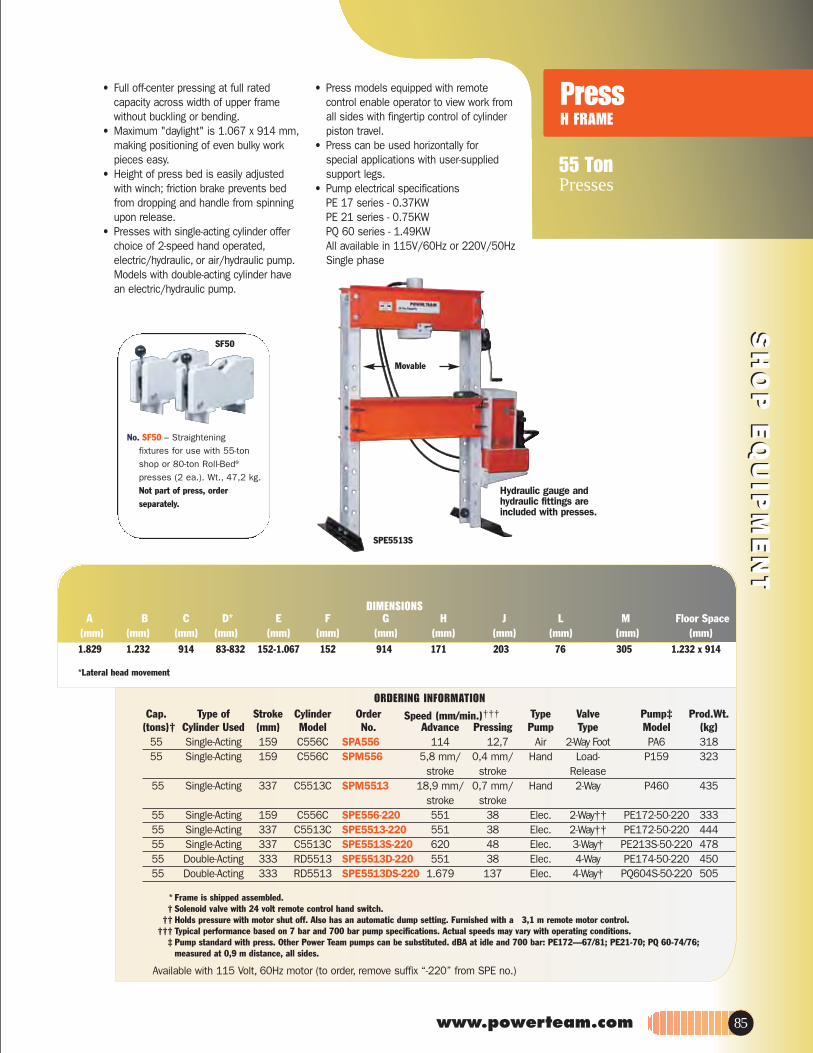
SH
OP
EQ
UIP
ME
NT
SH
OP
EQ
UIP
ME
NT
55 TonPresses
PressH FRAME
www.powerteam.com
Available with 115 Volt, 60Hz motor (to order, remove suffix “-220” from SPE no.)
.tW.dorP‡pmuPevlaVepyTredrOrednilyCekortSfo epyT.paC(tons)† Cylinder Used (mm) Model No. Advance Pressing Pump Type Model (kg)
55 Single-Acting 159 C556C SPA556 114 12,7 Air 2-Way Foot PA6 31855 Single-Acting 159 C556C SPM556 5,8 mm/ 0,4 mm/ Hand Load- P159 323
stroke stroke Release55 Single-Acting 337 C5513C SPM5513 18,9 mm/ 0,7 mm/ Hand 2-Way P460 435
stroke stroke55 Single-Acting 159 C556C SPE556-220 551 38 Elec. 2-Way†† PE172-50-220 33355 Single-Acting 337 C5513C SPE5513-220 551 38 Elec. 2-Way†† PE172-50-220 44455 Single-Acting 337 C5513C SPE5513S-220 620 48 Elec. 3-Way† PE213S-50-220 47855 Double-Acting 333 RD5513 SPE5513D-220 551 38 Elec. 4-Way PE174-50-220 45055 Double-Acting 333 RD5513 SPE5513DS-220 1.679 137 Elec. 4-Way† PQ604S-50-220 505
* Frame is shipped assembled.† Solenoid valve with 24 volt remote control hand switch.
†† Holds pressure with motor shut off. Also has an automatic dump setting. Furnished with a 3,1 m remote motor control.††† Typical performance based on 7 bar and 700 bar pump specifications. Actual speeds may vary with operating conditions.
‡ Pump standard with press. Other Power Team pumps can be substituted. dBA at idle and 700 bar: PE172—67/81; PE21-70; PQ 60-74/76; measured at 0,9 m distance, all sides.
Speed (mm/min.)†††
ORDERING INFORMATION
*Lateral head movement
A B C D* E F G H J L M Floor Space (mm) (mm) (mm) (mm) (mm) (mm) (mm) (mm) (mm) (mm) (mm) (mm)1.829 1.232 914 83-832 152-1.067 152 914 171 203 76 305 1.232 x 914
DIMENSIONS
No. SF50 – Straighteningfixtures for use with 55-tonshop or 80-ton Roll-Bed®
presses (2 ea.). Wt., 47,2 kg. Not part of press, order separately.
SF50
• Full off-center pressing at full rated capacity across width of upper frame without buckling or bending.
• Maximum "daylight" is 1.067 x 914 mm,making positioning of even bulky work pieces easy.
• Height of press bed is easily adjusted with winch; friction brake prevents bed from dropping and handle from spinning upon release.
• Presses with single-acting cylinder offer choice of 2-speed hand operated,electric/hydraulic, or air/hydraulic pump. Models with double-acting cylinder have an electric/hydraulic pump.
• Press models equipped with remote control enable operator to view work from all sides with fingertip control of cylinder piston travel.
• Press can be used horizontally for special applications with user-supplied support legs.
• Pump electrical specifications PE 17 series - 0.37KWPE 21 series - 0.75KWPQ 60 series - 1.49KWAll available in 115V/60Hz or 220V/50HzSingle phase
Hydraulic gauge andhydraulic fittings areincluded with presses.
SPE5513S
Movable
85

SH
OP
EQ
UIP
ME
NT
SH
OP
EQ
UIP
ME
NT
100, 150 & 200 TonPresses
H Frame Presses
† Frame is shipped assembled. ** Solenoid valve with 24 volt remote control hand switch.†† Typical performance based on 7 bar and 700 bar pump specifications. Actual speeds may vary under operating conditions.
‡ Pump standard with press. Other Power Team pumps can be substituted. dBA at idle and 700 bar: PE172—67/81; PQ60—74/76; PQ120—73/78. Measured at 0,9 m distance, all sides.
ORDERING INFORMATION
*Lateral head movement
A B C D* E F G H J L M Floor Space Cap (mm) (mm) (mm) (mm) (mm) (mm) (mm) (mm) (mm) (mm) (mm) (mm)100T: 1.962 1.626 914 178-1.092 51-1.067 203 1.270 203 254 86 381 914 x 1.988200T: 2.286 1.803 1.118 279-991 228-1.111 279 1.270 318 381 105 457 1.117 x 1.803
DIMENSIONS
Lower Bolster
• Cylinder workhead glides across upper frame on rollers, locks in place for off-center pressing jobs. May be used horizontally for special pressing applications with user-supplied supports.
• Press bed is raised and lowered by winch which locks in place for insertion of bed retaining pins. Upper bolster can be lowered for convenient positioning on repetitive jobs.
• Generous "daylight" accommodates bulky work pieces, uprights are placed for easy side entry of bars or shafts for straightening or bending.
• Choice of single- or double-acting cylinder. Hydraulic pump options include: 2-speed hand pump with large 7,6 l reservoir, PE172 electric/hydraulic pump or "PQ" series "Quiet" electric/hydraulic pump with low noise level.
PUMP ELECTRICAL SPECIFICATIONSPE17 Series – 0,37 KW, 220 volt,
50 cycle, single phase. Also available in 115 volt, 60 cycle,remove suffix "-220" from order no.
PQ60 Series – 1.49 KW, 220 volt,50 cycle, single phase. Also available in 115 volt, 60 cycle,remove suffix "-220" from order no.
PQ120 Series – 2,24 KW, 380V,50 Hz, three phase. (Suitable for 415V/50Hz/3 Phase)Also available in 460V/60Hz/3 phase, remove suffix “-380” from order no. (Suitable for 440V/50Hz/3 Phase)
SF150
No. SF150 – Straighteningfixtures for use with 100-tonshop press and 100-, 150-,and 200-ton RollBed®
presses (2 ea.). Wt., 89 kg. Not part of press,order separately.
.tW .dorP‡pmuPevlaVepyTredrOrednilyCekortSfo epyT.paC(tons)† Cyl. Used (mm) Model No. Advance Pressing Pump Type Model (kg)100 Single-Acting 260 C10010C SPM10010 9,0 mm/ 0,3 mm/ Hand 3-way P460 769
stroke stroke100 Single-Acting 260 C10010C SPE10010-220 889 74 Elec. 3-way PQ603-50-220 813100 Single-Acting 260 C10010C SPE10010R-220 292 20 Elec. 2-way PE172-50-220 766100 Double-Acting 333 RD10013 SPE10013DS-380 889 147 Elec. 4-way** PQ1204S-50-380 854150 Double-Acting 333 RD15013 SPE15013DS-380 610 99 Elec. 4-way** PQ1204S-50-380 1.366200 Double-Acting 333 RD20013 SPE20013DS-380 457 74 Elec. 4-way** PQ1204S-50-380 1.484
Speed (mm/min.)††
Hydraulic gauge and hydraulic fittings
are included with presses.
SPE10013DS
Movable
86

SH
OP
EQ
UIP
ME
NT
SH
OP
EQ
UIP
ME
NT
1000 - 2000 kg
Mobile Floor Cranes
www.powerteam.com 87
FC2200 FC4400Order No.:
Cap., boom ret. (kg) 1,000 2,000Cap., boom ext. (kg) 750 1,500A Max. boom hgt., ret (mm) 2,718 2,819B Max. boom hgt., ext.(mm) 2,972 3,099C Overall hgt., boom horiz.(mm) 2,032 2,083D Overall length (mm) 2,108 2,261E Min. throat width (mm) 610 635F Inside leg length (mm) 1,372 1,461G Eff. boom reach -ret.(mm) 838 902H Eff. boom reach -ext. (mm) 1,219 1,238J Inside leg width (mm) 610 - 914 - 1,219 660 - 1,016 - 1,333
(3 –position) (3 –position)142302)mm( thgieh geLK
L Dolly wheel diameter(mm) 127 127M Wheel diameter (mm) 152 203N Caster diameter (mm) 152 152
space, folded (mm) 686 x 965 787 x 1,067Height, folded (mm) 2,007 2,184
DIMENSIONS
• Adjustable legs spread to clear obstacles,telescoping boom for extra reach. Rugged construction, reliable hydraulics.
• Boom collapses completely and legs fold for compact storage.
• 2-speed hydraulic hand pump provides fast boom travel and precise operator controlled descent.
• Roller bearing wheels and a steering dolly provide ease of mobility. Lifting chain is included.
No. FC4400 – 2000 kg cap. crane with fold-away feature, adj. leg spread, lifting chain and 2-speed hand pump. Wt.293 kg.
1000 kg and 2000 kgcapacity with space-saving
fold-away feature
AdjustableLegs
Pump has asafety relief valve.
Crane is locked inposition whenwheels are lifted.
Load-lowering valveprovides controlled descent.
U.S. Patent No. 3,367,512Patented 1969 Canada
Piston rod isground andhard chromeplated.FC2200
Load-Rotors (Tilters)• For lifting or positioning components, POWER TEAM’S heavy duty lifting slings are available (consult factory)

SH
OP
EQ
UIP
ME
NT
SH
OP
EQ
UIP
ME
NT
Roll-Bed® Press
80-200 TonH Frame
• The original, patented Roll-Bed® design. Bed rolls out for easy loading and unloading with a crane or other lifting device.
• Movable workhead glides easily side-to-side for full off-center load capacity across width of upper frame.
• "Daylight" is 1.283 x 1.524 mm for 80- and 100-ton models; 1.302 x 1.625 mm on 150- and 200-ton presses.
• Fast approach of double-acting, 334 mm stroke cylinder is provided by PQ1204S "Quiet" electric/ hydraulic pump with remote control hand switch. Operator can view work from all sides with fingertip control of cylinder piston travel.
PRESS FEATURES: • Roll-Bed® design – Bed glides in or out on
bearings to make loading and unloading fast and easy.
• Adjustable lower bed width – For secure balancing and centering of heavy jobs. Loosen adjusting bolts to adjust bed from 102 to more than 686 mm. See dimension "H."
• Movable workhead – For off-center pressing jobs, workhead moves on bearings across upper bolster. Presses can be used at full capacity, regardless of where workhead is placed.
• Lifting mechanism – Simply turn crank handle to raise or lower upper bolster. Screw mechanism raises or lowers both sides evenly (a heavy-duty 1/2" drill motor can replace handle for automatic adjustment). Four locking pins hold bolster in place for pressing.
• Optional heavy-duty straightening fixtures – Make straightening jobs easy and accurate to within 0.1 mm! Rollers are ball bearing mounted and handle raises or lowers for easy turning of the work.
PUMP ELECTRICAL SPECIFICATIONS PQ120 Series – 2,24 KW, 380 volt,
50 cycle, three phase.
NOTE: Different voltage and valve options canbe obtained by substituting certain PA, PE orPQ series pumps. Consult the factory.
Movable
Hydraulic gauge andhydraulic fittings are
included with presses.
RB10013S
Heavy-Duty Straightening Fixtures
No. SF50 – Fixtures for usewith 80-ton Roll-Bed®
presses or 55-ton heavy-dutyshop presses. (2 ea.).Wt. 47,2 kg. Not part of press,order separately.
No. SF150 – Fixtures for use with 100-, 150- and 200-ton Roll-Bed® presses and 100-ton shop presses only (1 pr.). Wt.89 kg. Not part of press,order separately.
88

SH
OP
EQ
UIP
ME
NT
SH
OP
EQ
UIP
ME
NT
www.powerteam.com
* Solenoid valve with 24 volt remote control hand switch. † Frame is shipped assembled. ‡ Pump standard with press. Other Power Team pumps can be substituted. dBA at idle and 700 bar: PQ120-73/78; measured at 0,9 mdistance, all sides.
†† Typical performance based on 7 bar and 700 bar pump specifications. Actual speeds may vary with operating conditions.
Available with 460Volt, 60Hz, 3-phase motors (to order, remove suffix “380” behind press order number), suitable for 440V, 50Hz, 3 phase.380V/50Hz/3 phase also suitable for 415V/50Hz/3 phase.
Speed (mm/min.)†† .tW .dorP‡pmuPevlaVepyTredrOrednilyCekortSfo epyTyticapaC(tons)† Cylinder Used (mm) Model No. Advance Pressing Pump Type Model (kg)
80 Double Acting 333 RD8013 RB8013S-380 1.168 190 Elec. 4-way* PQ1204S-50-380 1.307100 Double Acting 333 RD10013 RB10013S-380 889 147 Elec. 4-way* PQ1204S-50-380 1.334150 Double Acting 333 RD15013 RB15013S-380 610 99 Elec. 4-way* PQ1204S-50-380 2.019200 Double Acting 333 RD20013 RB20013S-380 457 74 Elec. 4-way* PQ1204S-50-380 2.059
Cap A B C D E F G H J K L M Floor Space(Tons) (mm) (mm) (mm) (mm) (mm) (mm) (mm) (mm) (mm) (mm) (mm) (mm) (mm)
80 2.861 1.632 1.283 686 305-1.524 368-914 76,2 102-692 203 927 86 381 1.632-1.537
100 2.861 1.632 1.283 686 305-1.524 368-914 76,2 102-692 203 927 86 381 1.632-1.537
150 3.131 1.734 1.302 762 229-1.626 352-949 76,2 102-689 279 946 105 457 1.734-1.607
200 3.131 1.734 1.302 762 229-1.626 352-949 76,2 102-689 279 946 105 457 1.734-1.607
ORDERING INFORMATION
DIMENSIONS
Lower Bolster
Width adjusts from 102 mm to over 686 mm; is secured with locking bolts.
Bearings make bed positioning smooth
and easy.
Cylinder is easily moved across width
of upper bolster.
Lever lowers bed for pressing, raises it
for rolling.
Lifting screw and lockingpins make bolster raising
a one-man job.
89

JACKS
Page
ECONOMY TOE JACKS…93
2-10 Ton
Page
…93TOE JACKS51/2 - 271/2 Ton
Page
…91LOW PROFILE
BOTTLE JACKS12-30 Ton
Page
BOTTLE JACKS…912-110 Ton
Page
…92TELESCOPING JACKS
BOTTLE JACKS6-15 TON
Page
…96-99PORTABLE HIGH
TONNAGE RAILROADJACKS 55-300 Ton
Page
…100-101INFLATABLE JACKS
1-74 Ton
Page
…92SIDEWINDER JACKS
5-20 TON
90
Page
…95POST TENSION JACKS
20-30 Ton
Page
…94MAINTENANCE SETS

www.powerteam.com
9012A 9020A9130A
cirteMeldnaHpmuPpmuP .oN thgieHhtgneLdetcarteRHeight of Screw w/Screw Strokes to Saddle Handle Effort at tons Product
Cap. Stroke Order Min. Ext. Ext. Ext. Piston Dia. Base Size Length Rated Cap. Carry at 700 WeightTons (mm) Number (mm) (mm) (mm) (mm) (mm) (mm) (mm) (kg) Handle bar (kg)
12 95 9012A 171 76 343 26 48 165x106 605 27 Yes 10,9 6,4
20 86 9020A 181 40 305 22 51 183x129 800 32 Yes 18,1 10,1
30 79 9130A 181 –– 260 35 60 192x141 1.000 23 Yes 27,2 13,7‡ 2 Speed: Rapid advance 40 strokes; Lift mode 160 stroke
ORDERING INFORMATION
• All the quality, features and lifting capacity of the standard jacks in short form. The 12-ton and 20-ton models feature screw extensions for added versatility.
• All jacks meet ASME B30.1 standards and carry the Power Team Marathon Lifetime Warranty.
• All jacks operate both vertically and horizontally for use in a variety of lifting, pushing and spreading applications.
cirteMeldnaHpmuP pmuP .oNthgieH htgneLdetcarteRHeight of Screw w/Screw Strokes to Saddle Base Handle Effort at tons Product
Cap. Stroke Order Min. Ext. Ext. Ext. Piston Dia. Size Length Rated Cap. Carry at 700 Weight Tons (mm) Number (mm) (mm) (mm) completly (mm) (mm) (mm) (kg) Handle (bar) (kg)2 114 9002A 181 49 344 5 25 110x65 311 34 No 1,8 2,23 114 9003A 191 60 365 10 29 114x72 489 20,4 No 2,7 2,65 121 9005A 200 70 391 12 35 132x76 545 24,9 No 4,5 3,68 121 9008A 200 70 391 18 38 152x89 605 34 No 7,3 5,512 149 9112A 241 79 470 26 48 165x106 605 27,2 Yes 10,9 7,915 156 9015B 230 110 495 27 60 130x140† 700 40,8 No 13,6 8,320 159 9120A 270 40 429 22 51 183x129 800 31,7 Yes 18,1 12,922 156 9022B 240 110 505 36 60 165x160† 700 40,8 Yes 20,0 10,730 159 9030A 279 –– 438 35 60 192x141 1.000 22,7 Yes 27,2 18,733 143 9033B 240 100 483 56 65 184x176† 700 39,9 No 29,9 14,550 171 9050A 305 –– 476 35 76 237x187 1.000 38,6 Yes 45,4 35,4110 156 9110B 300 –– 456 40/160‡ 111 339x291 700 35,8 Yes 99,8 70
† Comes with a Beveled Base‡ 2 Speed: Rapid advance 40 strokes; Lift mode 160 strokes
ORDERING INFORMATION
• Choose from this complete line of premium–quality, standard bottle jacks. Ideal for use in any number of industrial lifting and pushing applications.
• The 9110B, 9015B, 9022B and 9033B feature a beveled base which allows the jack to "follow" the load, reducing the chance of dangerous side-loading.
• Many jacks feature screw extensions and all can be used in the vertical, angled or horizontal positions.
• Serrated or contoured saddles help stabilize the load for a safer lift.
• All jacks meet ASME B30.1 standardsand carry the Power Team Marathon Lifetime Warranty.
• 110-ton jack features dual pumps for time-saving two-speed operation.
9033B
9112A
9008A
JAC
KSJA
CKS
Industrial lifting and pushing applications.
2-110 TonPortable hydraulic power
Bottle Jacks
Standard
For Low Clearance Jobs
Low Profile
91

JAC
KSJA
CKS
5-20 TonPortable hydraulic power
Bottle Jacks 9015X9006X 9011X 9013X
ASME B30.1
Retracted Length Height No. Pump Base Size Pump Handle MetricHeight of Screw w/Screw Strokes to Saddle Beveled Handle Effort at tons Product
Cap. Stroke Order Min. Ext. Ext. Ext. Piston Dia. Base Length Rated Cap. Carry at 700 WeightTons (mm) Number (mm) (mm) (mm) 25,4 mm (mm) (mm) (mm) (kg) Handle bar (kg)
6 305 9006X 216 –– 521 14 44 121 x 133 700 36 No 5,4 6,411 262 9011X 200 68 530 25 41 160 x 165 700 40 No 10,0 8,813 254 9013X 230 84 570 35 48 176 x 186 700 36 Yes 11,8 11,315 181 9015X 170 70 419 32 52 143 x 194 600 43 Yes 13,6 12
ORDERING INFORMATION
• Telescoping jacks offer all of the quality features and capabilities of the standard bottle jack line with a bonus. The super-long stroke of these jacks saves time and effort by eliminating the need to lift, crib, lift, etc. In most applications, the user can place the jack once and complete the lift.
• The 9015X offers very low clearance capability, making it the ideal choice for forklift maintenance or machine lifting. • The taller 9006X, 9011X and 9013X all feature a unique beveled base that allows the jack to "follow" the load laterally
as it is raised, greatly reducing side-loading of the piston.
9105A
ASME B30.1
9210A
cirteMeldnaHpmuPpmuP .oNdetcarteRHeight Max Strokes to Saddle Base Handle Effort at tons Product
Cap. Stroke Order Min. Height Ext. Piston Dia. Size Dia. Length Rated Cap. Carry at 700 WeightTons (mm) Number (mm) (mm) 25 mm (mm) (mm) (mm) (kg) Handle bar (kg)
5 19 9105A 63,5 85,7 30 29 73,8 240 26 No 4,5 1,95 38 9205A 88,9 130,2 38 29 73,8 240 26 No 4,5 2,410 30 9210A 120,7 149,2 36 42,1 109,9 440 28 No 9,1 5,520 30 9220A 130,2 160,3 46 52,8 119,9 605 35 No 18,1 8,0
ORDERING INFORMATION
• Retracted height of just 63,5 mm for the smallest jack and 130,2 mm for the 20 ton, allows you to slip this jack into the narrowest of crevices.
• Jacks operate either horizontally or vertically. Handles function in line with base for easier use in confined spaces.
• The perfect addition to any toolbox,this remarkable little jack has multiple uses that are limited only by your imagination. Use it as a jack or a spreader. Use it to turn your mechanical gear puller (puller capacity must match jack capacity) into a hydraulic puller. Use it vertically or horizontally in limited clearance.
Telescoping Jacks
Sidewinder Jacks
92

JAC
KSJA
CKS
The right choice for thoselower clearance jobs.
2 to 27.5 Ton
Toe Jacks
www.powerteam.com
J109T J58TJ259T
J24T
J55T J106T
ASME B30.1
• With lifting points on the toe and on the top, these extremely rugged jacks are ideal for machine lifting, rigging, lift truck service and much more.
• Choose from 5.5-ton, 11-ton, and now, an amazing 27.5-ton lifting capacity.
• All jacks operate both vertically and horizontally.• Base, toe and pumping assembly swivel independently, allowing the jack
to work in confined areas.• Get under equipment with only 27mm of ground clearance.
• These bottle jack-style toe jacks are loaded with many of the same features as our standard bottle jacks, but the toe-lift feature and swiveling pump handle socket make them ideal for machinery lifting and positioning.
• An internal pressure relief provides added safety by limiting the jack's lifting capability to the capacity of the toe.
• Spring return is an added feature on the larger jacks.
• Swiveling pump handle assembly available on the 5- and 10-ton models. The swiveling jack assembly allows you to access and pump the unit from numerous positions.
Strokes Handle Effort Metricto Extend at Max tons at Product
Cap. Max Lift Order Piston Load Carry 700 Wt.Tons Stroke (mm) Number 25,4 mm (kg) Handle bar (kg)51/2 210 J58T 8 38,1 Yes 5,0 19,511 235 J109T 13 40 Yes 10,0 29
271/2 233 J259T 21 40 Yes 24,9 92,1
ORDERING INFORMATION
A B C D E F G H JOrder Ret. Ext. Ret. Ext.
Number (mm) (mm) (mm) (mm) (mm) (mm) (mm) (mm) (mm) (mm) (mm)30 238 375 584 368 451 71 56 176 41 13030 264 419 654 368 451 76 56 183 64 171
J58TJ109TJ259T 54 289 505 738 210 756 146 102 267 89 270
DIMENSIONS
Width ofBase
Retracted
Retracted
Extended
ExtendedWidthof Toe
Max Lift Strokes to Handle Effort Metric Product Cap. Stroke Order Extend Piston at Max Load Carry tons at Wt.Tons (mm) Number 25 mm (kg) Handle 700 bar (kg)
2 121 J24T 14 19 Yes 1,8 8,35 121 J55T 22 27 Yes 4,5 2410 146 J106T 31 33 Yes 9,1 38
ORDERING INFORMATION
A BOrder Ret. Ext. Ret. Ext. C D E F
Number (mm) (mm) (mm) (mm) (mm) (mm) (mm) (mm)16 140 232 356 47,5 181 51 12525 149 292 476 47,5 257 191 157
J24TJ55TJ106T 32 181 327 476 64 292 100 241
DIMENSIONS
Retracted
Retracted
Extended
Extended
Width of Toe
93

JAC
KSJA
CKS
Hydraulic SystemComponents
Maintenance Sets
94
IM10E-220
IM10H
• Matched hydraulic system components, adapters and hydraulic spreader, contained in a rugged carrying and storage case.
• Portable sets are ideal for pushing, pulling, lifting, straightening, or clamping at remote job sites.
• Cylinders in set are rated at 10 tons at 700 bar. Set components are designed for full rated capacity of cylinders.
• Set IM10H includes hand operated pump. • Set IM10E-220 includes the Quarter Horse®
electrically driven portable power unit (220/230V, 50/60Hz, Single Phase).
APPLICATION FLEXIBILITY
ORDERING INFORMATION TES FO STNETNOC IM10E-220
Description Order No. Hydraulic spreader HS2000
2-22001EP Electric hydraulic pump 1409 eguag .dyh rab 007 0769 retpada eeT 4579 ylbmessa relpuoc & esoH 59352 esab V °09 46652 relpuoc dedaerhT 27713 elddas detarreS 52323 esab talF
Extension rod – 127mm length 350897 Extension rod – 254 mmlength 38909 Extension rod – 457 mm length 350898
260024 esab troppus .lyC Cyl. ass’y, 10 ton, 257 mm stroke C1010CBT Cyl. ass’y, 10 ton, 156 mm stroke C106CBT
227053 x*ob egarotS Prod. Weight – 48,1 kg.
CONTENTS OF SET IM10H IM10L .oN redrO .oN redrO noitpircseD
Hydraulic spreader HS2000 HS2000 Hand pump P59 P59L 700 bar hyd. gauge 9041 9041 Tee adapter 9670 9670 Hose & coupler assembly 9754 9754 90° V base 25395 25395 Threaded coupler 25664 25664 Serrated saddle 31772 31772 Flat base 32325 32325 Extension rod - 127mm length 350897 350897 Extension rod - 254mm length 38909 38909 Extension rod - 457mm length 350898 350898 Cyl. support base 420062 420062 Cyl. ass’y, 10 ton, 156mm stroke C106CBT C106CBT Storage box* 350722 350722
thgieW .dorP thgieW .dorP .gk 8,63 .gk 4,04
* Actual product may differ from photo.

JAC
KSJA
CKS
20 & 30 Ton
Post Tension
www.powerteam.com 95
A BOrder Ret. Ext. Ret. Ext. C D E F
DIMENSIONS
& STRESSING JACKS
SJ2010SJ3010
SJ2010DASJ3010DA
ORDERING INFORMATION
• Power Team Monostrand Stressing Jacks are the most durable in the industry.
• Ideally suited for work on slab-on-grade where dirt, heat and high volume use take their toll.
• Available in single- or double-acting models.
• Standard single-acting units have
a 254 mm stroke. Other stroke lengths are available on special order.
• Dead-end seaters for production work and field work available on special order. (Part #400120)
• Service repair is simple; components are long lasting and easily replaced.
• 76,2 mm detachable seater nose assembly easily replaced with optional 152,4 mm nose assembly.
• The jack of choice for high-rise and elevated work, thanks to fast return time and light weight.
• All hydraulic fluid controls are interior designed; more efficient
and safer operation during tensioning and retraction.
• Standard double-acting units have an 216 mm stroke; others available on special order.
• Specially designed Power Team Control Valves are available for post tensioning jacks.
dnartS liO dednemmoceR .lyC thgieW ta snoT retaeS retemaiD yticapaC siht rof spmuP redrO ekortS .paC
)gk( rab 007 epyT )mm( )l( kcaJ gnissertS rebmuN )mm( snoT noitpircseDPost tension jack with spring seater, 20 254 SJ2010 PE554T/PE604T 0,72 11,1-12,7 Spring 20,3 2512,7 mm strand.Post tension jack with power seater, 20 254 SJ2010P PE604PT 0,72 11,1-12,7 Power 20,3 2512,7 mm strand.Double-acting post tension jack with 20 215 SJ2010DA PE554PT/PE604PT 0,85 11,1-12,7 Power 23,9 19power seater, 12,7 mm strand.Post tension jack with spring seater, 30 254 SJ3010 PE554T/PE604T 1 11,1-15,2 Spring 28,5 34,515,2 mm strand.Post tension jack with power seater, 30 254 SJ3010P PE604PT 1 11,1-15,2 Power 28,5 34,515,2 mm strand.Double-acting post tension jack with 30 215 SJ3010DA PE554PT/PE604PT 1,1 11,1-15,2 Power 36,0 23,5power seater, 15,2 mm strand.
Used with 76,2 mm 76,2 mm 152,4 mm 152,4 mm 9,5 mm 11,1 mm 12,7 mm 15,2 mm Stressing Nose Wedge Nose Wedge Diameter Diameter Diameter Diameter Replacement Jack Piece Seater Piece Seater Gripper Set Gripper Set Gripper Set Gripper Set Gripper Handle
SJ2010 252564 252562 252759 252763 252568 252761 252567 NA 252570 252565SJ2010P 252564 252562 252759 252763 252568 252761 252567 NA 252570 252565SJ2010DA 252543 252542 252760 252764 252650 252762 252555 NA 252556 252544SJ3010 252564 252562 252759 252763 252568 252761 252567 252569 252570 252565SJ3010P 252564 252562 252759 252763 252568 252761 252567 252569 252570 252565SJ3010DA 253363 253361 253364 253362 253390 NA 253391 253365 252556 252544
No. 9758 Hose – 3,1 m rubber, wire-braid (2-ply, 1,400 bar burst rating) 3/8” NPTF male hose ends No. 9763 Hose – 3,1 m rubber, wire-braid (2-ply, 1,400 bar burst rating) 3/8” x 1/4” NPTF male hose ends
GripperRetainer Plate
(2 used)
STRESSING JACK ACCESSORIES AND HOSES–ORDERING INFORMATION

JAC
KSJA
CKS
Portable & compact, ideal for locomotive and railcarmining.
60-100 Ton
Portable HIGH TONNAGE JACKS
96
Railroad Edition
• High-profile, low rolling resistance, foam-filled tires. Jack can be moved and positioned with minimal effort. No chance of downtime due to punctured tires.
• Electric and air motor options. Quiet, powerful air and electric motor powered units available.
Power Motor Valve Power dBa at Order No. Motor Req. Control Function Cord 700 bar 0,84 kW, 220 12 amps 6,1 m Lift Hold Pigtail 80/95 VAC***, 50 Hz Remote Lower Single Phase Control Manual
PLE6014-220
PLA6014 Rotary Air 1,4 cu.m 6,1 m Lift Hold NA 82 Powered at 6 bar Remote Lower Air Control Manual
*** For 110/115V-50/60 Hz order PLE6014
POWER UNIT SPECIFICATIONS
5 position adjustable handle.
Cribbing blocks with handles and
storage racks.
6,1 m remote on/off switch.
Reliable Vanguard Pump. THE PROVEN LEADER in the
field for over 30 years.
Patented load control system
for chatter-free lowering of load.
406 mm foam-filled tires.
All steel cylinder is threaded into base.
Steel base not prone to cracking like cast.
Heavy-duty 60-ton lifting capacity.
Extensions fit over and around piston giving maximum stability side load protection.
Cribbing interlocks with body.
Safety pin to secure extension to cylinder.
Reach heights up to 1 778 mm with just 7 extensions.
• Patented load lowering valve. Lowers load smoothly and safely. Eliminates dangerous chatter and bounce.
• Full range of rod extensions. Jack comes fully equipped with extensions to match lifting pad heights on most rolling stock. Max. lifting height to 1 778 mm .
• Low collapsed height, long stroke. 610 mm collapsed height for low-clearance lift pads. 360 mm stroke for maximum lift.
• Adjustable, ergonomic handle. Handle tilts to start the job and is easily locked/unlocked without moving from operating position.
• Cribbing block set with handles and convenient storage rack. Provides solid mechanical load holding.
• Contact factory for:-- lower collapsed height- custom cribbing block sizes- custom piston rod extensions

www.powerteam.com 97
JAC
KSJA
CKS
PLE6014 = Jack, Electric (115 V), includes: Cart, Pump & CylinderPLE6014-220 = Jack, Electric (220 V.) includes: Cart, Pump & CylinderPLA6014 = Jack, Air, includes: Cart, Pump & CylinderCBS60 = Cribbing Block Set (5 cribbing blocks)PL60EXT = Extension Set (Consists of 7 extensions)
60 356 *PLA6014K 610 1.778 237 60 356 *PLE6014K-220 610 1.778 237 100 356 Consult Factory 610 1.499 237
*Includes cribbing block set stored on jack handle rack, and 7 extensions (25,4; 50,8; 76,2; 101,6; 127; 254 and 308 mm)
Air Model (PLA6014K)
Electric Model (PLE6014K)
LIFTING RANGE
Lifting range (in 25,4 mm increments): 610 mm- 1.778 mm.
Only 3 extensions are needed to provide this range.
Do NOT exceed 1.778 mm lifting range on 60-ton unit or 1.489 mm on 100-ton unit.
EXTENSIONS(PL60 EXT, INCLUDED)
Extension Extension Length Order Weight (mm) Number (kg) 25,4 351931 2,2 50,8 351927 4,0 76,2 351928 6,4 101,6 351929 8,7 127 66053 9,5 254 66054 13,8 508 66055 22,1
CRIBBING BLOCKS(CBS60, INCLUDED)
Qty. Height (mm) Order Number 1 38,1 351954 4 76,2 351953
ORDER INFORMATION Retracted Extended Ht. Product Wt. Capacity Stroke Height w/Extensions Less Cribbing (Tons) (mm) Order Number (mm) (mm) & Ext. (kg)

JAC
KSJA
CKS
Portable and compact, ideal for locomotive/railcar, mining and heavyequipment maintenance.
55, 100, 150, 200 & 300 Ton
Portable HIGH TONNAGE
98
• Increases jack’s reach. • Swivel cap (5° max.) provides more secure load holding.
CBS300 (300 Ton): Consult Factory
A B C D E F G H Prod. Wt.(Tons) No. (mm) (mm) (mm) (mm) (in.) (mm) (mm) (mm) (kg)55 58945 223,8 173 127 66,8 111/16–8UN 63,5 66,8 92,2 9,5
100 58943 228,6 177,8 174,7 98,6 23/4–12UN 95,3 98,6 95,3 18,2
150 58944 219,2 168,4 203,2 114,3 31/4–8UNC 111,3 114,3 88,9 22,7
ORDER INFORMATION
JACK MODULE EXTENSIONS
55 Ton 100 Ton 150 Ton 200 TonOrder No. CBS55 CBS100 CBS150 CBS200
ORDER INFORMATION
CRIBBING BLOCK SETS - INCLUDES ONE JACK MODULE EXTENSION
• Modular design - pump and cart separate from cylinder and base.
• Five tonnage capacity options - 55-ton,100-ton, 150-ton, 200-ton and 300-ton.
• Three collapsed height options – 660, 838 and 1,143 mm.
• Two standard power options - air (PA55) and electric (PE55).
• Two control options - remote motor control and remote valve/motor control.
• Accessory options – 168 mm extension,load-holding rings.
• Select the collapsed height to fit your most frequent application - add jacking modules to suit your needs.
• Remote operation for maximum operator safety and control - choose "motor only" or "motor and valve" control in the hand.
• Easy to maneuver - large tires and small "footprint" make it easy to scoot into the tightest quarters, then locate the exact lifting position.
• Adjustable, heavy-duty handle - makes this jack easy to move, position under vehicles. Can also be used to transport jack on site with a forklift.
• Load-holding rings (optional) - provide full rated mechanical load-holding capability.
• Cylinder extension (optional) - adds more versatility by extending your jack’s reach.
• Low-temperature oil (optional) - provides smooth, reliable operation in the coldest climate conditions.
• Modular design - allows you to change lifting modules to suit your tonnage or height requirements. Use the pump module as a portable power station for your other double-acting cylinders (700 bar ).
• Exclusive load-control system - provides positive, chatter-free control when lowering the load.
• Shielded and sheltered hydraulic lines - for safer, longer, trouble-free service.
Patented load controlsystem for chatter-free lowering of loads.
Electric or airhydraulic systems
available.
Shieldedhydraulic lines
for greater safety.
Adjustablehandle formaximum
control.
6,1mremote
control.5° swivelcap providesmore secureload holding.
55-, 100- 150-, 200- and300-ton capacities
Large urethane-filled tiresprovide durability andeasy maneuverability.
Steel basenot prone
to crackinglike cast.
Modular design allows forquick interchange of pumpwith other modules.
• Convert jack moduleinto stable mechanicalcribbing device.
• Increase retracted heightup to 521 mm inches.
No. in Set 1 4 1 4 1 4 1 4 A 38,1 76,2 38,1 76,2 38,1 76,2 38,1 76,2 B 44,5 82,5 44,5 82,5 44,5 82,5 44,5 82,5 C 139,7 139,7 187,3 187,3 222,2 222,2 254 254 Jack Module Ext. 173 177,8 168,3 168,3 Total Stack Ht. 515,9 520,7 511,2 511,2 Product Wt. (.kg) 16,3 30,9 38,6 47,6

www.powerteam.com
JAC
KSJA
CKS
Capacity Ret. Height Ext. Height Stroke Pump Power Valve Remote Order(tons) (mm) (mm) (mm) Type Required Type Control No.
55 660,4 994 333 Electric 25 amps Manual M JEM5526†
100 838,2 1.172 333 Air 1,4 cu m /min at 6 bar Manual M JAM10033100 838,2 1.172 333 Air 1,4 cu m /min at 6 bar Air Pilot M & V JAR10033150 660,4 994 333 Electric 25 amps Manual M JEM15026†
†150 838,2 1.172 333 Air 1,4 cu m/min at 6 bar Manual M JAM15033200 711 1.044 333 Electric 25 amps Remote M & V JER20026300 838,2 1.172 333 Air 1,4 cu m /min at 6 bar Air Pilot M & V JAR30033
†110V / 115V 60Hz Single phase motor. (220V / 50Hz / 60Hz Single phase motor upon request, please specify when ordering)Different Modules Configuration available upon request.
* Collapsed height: 711 mm & Cylinder Stroke: 333 mm** Cylinder Stroke 333 mm*** Must use PMx355x versions of pump/cart modules above.
ORDER INFORMATION – Pump and Cart Modules with Assembled Jack Module
DIMENSIONS (MM)
Model Series A B C D E F G H
PMA & PME 1.464 752 1.353 762 872 594 *70° 406 mm
* Total range with varying degree increments. Tire Dia.
Remote ControlPump Motor Only Motor & Valve
Air PMA55 PMA55SElectric (110V) PME55†
†† ††PME55S
Electric (220V) PME55-50-220 PME55S-50-220†
PMA355†† ††
PMA355SPME355-50-220 PME355S-50-220
Collapsed Height Cylinder Stroke 26” 33” 45” Tonnage (mm) 660mm 838mm 1,143mm 55 333 JM25 JM35 JM45 100 333 JM210 JM310 JM410 150 460 JM215** JM315 JM415 200 460 JM220* JM320 JM420 300*** 333 JM300* JM330 JM430
†††
110V / 115V 60Hz Single phase motor.220V / 50Hz / 60Hz Single phase motor.
Jack modules (JM)Additional Jack Modules may be purchased for varying applications.
Pump & cart modules (PM)Pump and cart modules contain hydraulic pump,cart, remote control and all hoses and fittings required to connect to a jack module. Jack modules easily separate from the pump and cart module. Extra jack modules may be purchased for a wide variety of lifting applications.
99
AirElectric (220V)
PM Model
JM Model
371,6mm
279,4mm
*Retracted /Extended
Height
660 mm (26”)Jack Module
838 mm (33”)Jack Module
1,143 mm (45”)Jack Module
Air pump andcart module. (PMA)
Electric pumpand cart module. (PME)

JAC
KSJA
CKS
1-74 Ton
Inflatable Jack
100
• Highly flexible and lightweight jacks only require an air supply of 8 bar maximum. Any non-explosive gas or water can also be used for inflation.
• Uninflated jacks are only 25,4 mm thick, making seemingly impossible lifting tasks routine.
• Space age reinforced, multi-layer aramid construction, widely overlapping on all sides. Tested at 12 bar.
• In rugged testing, jacks withstood tens of thousands of inflate/deflate cycles at 8 bar.
• Large surface area and material flexibility allow jacks to lift loads on soft or compressible surfaces without support cribbing being necessary.
• Safety first! The controller, shut-off and air hoses are all equipped with USA industrial interchange style air couplers. Female half coupler bodies have a locking collar,protecting operator from accidentally disconnecting jack while under load.
• Surface of jack has a non-skid pattern, assuring that the jack won’t "walk away" from the job. Jacks can be used to lift a load from an uneven surface, are tolerant of side-loaded applications.
• Non-conducting material resists oil,ozone and most chemicals. Cold resistant down to -4° C, heat resistant up to 115°C(short term) or 93°C(long term).
• Field-replaceable nipples are made of tough steel, with internal thread to prevent abrasion damage. Ideal needle aperture of 6,4 mm allows rapid inflation, without risk of icing,and permits a safe lowering speed.
• Single jack controller with "dead man" control (350090). Can be used individually, or in multiples to regulate any number of jacks desired.
• Heavy attachment straps are provided on 4 largest sizes for attachment of a rope or hook to position the jack from a safe distance.
• Inflation hose system is color-coded (red and yellow) for easy recognition when using more than one jack.
Non-conductingmaterial
Sealed vulcanizednipple
Field replace-able nipple
Non-skidpattern
Multi-layer aramidconstruction
Jacks are only25,4 mm thick
Stack up to two jackstogether to increase
effective lifting height.
Maximum Effective Lifting AreaAll lifting capacities mentioned in the charts are measured at themaximum effective lifting area (A). As the jack is inflated (B), this effective area decreases (C) due to the rounded shape of the jack.Lifting capacity alsodecreases (see performance chart).
A
B
C
The non-skid space age reinforced inflatable jack is
perfect for many applications.
IJ Series InflatableAir Jacks

JAC
KSJA
CKS
www.powerteam.com 101
350090*
250341250353 25034215235286052343052
307159
350208350209
350207
tcudorPdespalloCgnikroW .xaMstnetnoC riAgnitfiLgnitfiLCap. Height Order at 8 bar Pressure Length Width Height Weight
(tons) (mm) Number (l) (bar) (mm) (mm) (mm) (kg)1,1 70 IJ13 2,3 8 140 130 25,4 0,53,6 120 IJ45 14,4 8 255 200 25,4 1,27 160 IJ76 42 8 305 305 25,4 1,912 225 IJ128 97 8 400 400 25,4 3,6
23,8 304 IJ2211 268 8 550 550 25,4 7,334 360 IJ3213 463 8 650 650 25,4 9,9
46,3 418 IJ4416 729 8 750 750 25,4 13,174,6 520 IJ7320 1.457 8 950 950 30,4 26,3
350207 Ass’y 350090 Ass’y
250353
307159
LIFTING CAPACITY OF INFLATABLE JACKS
TONS
80
70
60
50
40
30
20
10
00 70 120 160 225 304 360 418 520
MM
IJ7320 - 74.6 ton capacityIJ4416 - 46.3 ton capacityIJ3213 - 34 ton capacityIJ2211 - 28.8 ton capacityIJ128 - 12 ton capacityIJ76 - 7 ton capacityIJ45 - 3.6 ton capacityIJ13 - 1.1 ton capacity
307159250353
350208 (Red) or350209 (Blue)
350208 (Red) or350209 (Blue)
350208 (Red) or350209 (Blue)
350208 (Red) or350209 (Blue) 350208 (Red) or
350209 (Blue)
350207 Ass’y
350090 Ass’y(2 Req’d.)
InertGas
Bottle
InertGas
Bottle
350207 Ass’y
SINGLE LINE SYSTEM
DUAL LINE SYSTEM
No. 307159 – Pressure reducing valve. Allows use of bottled gases to operate jacks (works on CGA-580 Nitrogen/Argon/Helium bottles). Contains standard bottle fitting on inlet and 1/4" industrial interchange (female) outlet. Wt., 1,8 kg.
No. 350090 – Air controller for single jack. Equipped with relief valve and pressure gauge.
No. 350207 – Shut-off hose with shut-off valve and pressure relief valve. Includes a female and male quick coupler.
No. 350208 – Air hose. Red, 9,2 m long. Includes No. 250341 female and No. 250342 male quick coupler.
No. 350209 – Air hose. Same as 350208, except blue in color.
No. 250343 – Female quick coupler. 1/4" industrial interchange x 1/8" NPT female. Wt.,0,1kg.
No. 250353 – Male quick coupler. 1/4" industrial interchange x 1/8" NPT male. Wt., 0.1 kg.
No. 250682 – Female quick coupler. 1/4" industrial interchange x 1/4" NPT male. Wt., 0.1 kg.
No. 15235 – Connector 1/8" NPT male x 1/4" NPT female. Wt., 0.1 kg
No. 250341 – Female quick coupler. 1/4" industrial x 9,5 mm I.D. hose.
No. 250342 – Male Quick coupler. 9,5 mm I.D. Hose.
* NOTE: 350090 air controller may be used individually to control one jack (see single line system), or in multiples to control additional jacks (see dual line system).
ORDER INFORMATION
PERFORMANCE

102
HYDRAULICTOOLS
Page
…103-107TORQUE WRENCHES
Page
SPREADERS…1151 and 11/2 Ton
Page
…113PIPE FLANGE SPREADERS
5 and 10 Ton
Page
NUT SPLITTERS…11215 and 25 Ton
Page
…114PORTABLE PUNCHES
Page
TESTERS…118-119
egaP
BEAD BREAKERS…116Tire Removing Tool
egaP
C CLAMPS…117
Page
…120-121MECHANICAL TOOLS
egaP
…108-109ELECTRIC HYDRAULIC TORQUE
WRENCH PUMPS
egaP
…110-111AIR HYDRAULIC TORQUE
WRENCH PUMPS

www.powerteam.com
TORQUE WRENCH SELECTION GUIDE
Measurements/Specifications
HYD
RA
ULIC
TOO
LSH
YDR
AU
LIC TO
OLS
103
BOLT - TORQUE
SAE1SAE 2
30,000 PSI
1”1-1/8”
1-1/4”1-3/8”
1-1/2”
1-5/8”
1-3/4”1-7/8”
2”
2-1/4”
2-1/2”
2-3/4”
3”
3-1/4”3-1/2”
3-3/4”4”
4-1/4”
4-1/2”
4-3/4”6-1/2”
ASTM 193B7
BOLT
7/8”1”
1-1/8”1-1/4”
1-3/8”
1-1/2”
1-5/8”
1-3/4”
1-7/8”2”
2-1/4”
2-1/2”
2-3/4”
3”
3-1/4”
3-1/2”
3-3/4”4-1/4”
8-7 A/FHEAVY
HEX NUT
1-7/16”1-5/8”
1-13/16”2”
2-3/16”
2-3/8”
2-9/16”
2-3/4”
2-15/16”3-1/8”
3-1/2”3-7/8”
4-1/4”
4-5/8”
5”
5-3/8”
5-3/4”
ASTM 354B8
60000 PSI
7/8”
1”
1-1/8”
1-1/4”
1-3/8”
1-5/8”
1-3/4”
1-7/82”
2-1/4”
2-1/2”
2-3/4”
3”
3-1/4”
3-1/2”
FT. LBS.
300425500600700800900
1,0001.2501,3501,5001,6001,8002,0002,2002,6003,0003,7004,0004,4005,1006,0007,0008,0009,00010,00011,50013,00014,50015,50016,50019,50020,50021,50024,50025,50029,500
Torque Wrench Selection Guide
TWSD Series(Square Drive)
TWLC Series(Low Clearance)

Torque WrenchSQUARE DRIVE
TWSD SeriesMAX TORQUE 33496 Nm700 bar
104
HYD
RA
ULI
C T
OO
LSH
YDR
AU
LIC
TO
OLS
Tool Model Square Drive Max. Torque Tool Weight Drive mm (in.) Nm (ft. lbs.) kg TWSD1 19.0 1,880 1,390 2.3 TWSD3 25.4 1 4,160 3,070 4.5 TWSD6 8,157 6,020 7.9 TWSD11 14,823 10,940 13.1 TWSD25 33,496 24,700 29.5
Tool Model L1 (mm) L2 (mm) L3 (mm) H1 (mm) R (mm) W2 (mm) W1 (mm) TWSD1 139 170 112 146 29 87 34 TWSD3 169 196 124 176 39 105 45 TWSD6 195 237 142 206 46 136 51 TWSD11 234 292 179 242 55 165 61 TWSD25 306 375 231 314 72 200 77
SQUARE DRIVETORQUE WRENCHES• Low Weight, High Strength Design• Superior Torsional Strength• Fast Operation Cycle• Fine Tooth Pawl• Floating Piston Design• Internal Swivel Manifold Relief• Rigid Steel Body Construction• Compact Frame Size
Heavy duty simple-to-use. Accuracyand speed under load. Breaking nutsloose and torquing.
• Push Button Reversal of Square Drive• Corrosion Resistant Finish• 360˚ Reaction Arm• Push to Click Reaction Arms• Multi-Axis High Flow Swivel Manifold• Simple Design• Consistent Torque Output• Fully Enclosed Drive Mechanism• Accurate Torque Output• Marathon Lifetime Warranty
TWSD Series
Tool is shipped with standard reaction arm as shown.
TWSD1-LRATWSD3-LRATWSD6-LRATWSD11-LRATWSD25-LRA
Long Reaction Arm
(Optional)
TWSD1-ERATWSD3-ERATWSD6-ERATWSD11-ERATWSD25-ERA
Extended Reaction Arm
(Optional)
360º x 180ºSwivel
360º Reaction Arm
3/4
1/21/2
1/2
38.1 1- 38.1 1- 63.5 2-
TOPSIDESUB-SEA
APPLICATION

www.powerteam.com
Sockets & Allen DrivesSQUARE DRIVE
HYD
RA
ULIC
TOO
LSH
YDR
AU
LIC TO
OLS
105
HexDrive
ReactionPad
Reaction Pad L1 (mm) L2 (mm) L3 (mm) WIDTH (mm)
TWSD1-RP 71.5 115.5 43.5 63.0
TWSD3-RP 83.0 135.0 48.0 74.0
TWSD6-RP 91.0 154.0 57.0 90.0
TWSD11-RP 109.0 184.0 65.5 105.0
TWSD25-RP 135.0 242.0 88.5 143.0
Reaction Pads for Hex Drives (Optional)
Reaction Pad Sockets
HEX DRIVES (Allen Drives)
7/8 TWSIA088 TWSIB088 - - 1-1/16 TWSIA106 TWSIB106 - - 1-1/4 TWSIA125 TWSIB125 - - 1-3/8 TWSIA138 TWSIB138 - - 1-7/16 TWSIA144 TWSIB144 - - 1-5/8 TWSIA163 TWSIB163 TWSIC163 - 1-13/16 TWSIA181 TWSIB181 - - 2 TWSIA200 TWSIB200 TWSIC200 - 2-3/16 TWSIA219 TWSIB219 TWSIC219 - 2-3/8 TWSIA238 TWSIB238 TWSIC238 - 2-9/16 - TWSIB256 TWSIC256 - 2-3/4 - TWSIB275 TWSIC275 - 2-15/16 - TWSIB294 TWSIC294 - 3-1/8 - TWSIB313 TWSIC313 TWSIF313 3-3/8 - TWSIB338 TWSIC338 TWSIF338 3-1/2 - TWSIB350 TWSIC350 TWSIF350 3-3/4 - TWSIB375 TWSIC375 TWSIF375 3-7/8 - TWSIB388 - TWSIF388 4-1/8 - TWSIB413 TWSIC413 TWSIF413 4-1/4 - TWSIB425 TWSIC425 TWSIF425 4-5/8 - - TWSIC463 TWSIF463 5 - - - TWSIF500 5-3/8 - - - TWSIF538 5-3/4 - - - TWSIF575 6-1/8 - - - TWSIF613
22 TWSMA022 TWSMB022 - - 24 TWSMA024 TWSMB024 - - 32 TWSMA032 TWSMB032 TWSMC032 - 36 TWSMA036 TWSMB036 TWSMC036 - 41 TWSMA041 TWSMB041 TWSMC041 - 46 TWSMA046 TWSMB046 TWSMC046 - 50 TWSMA050 TWSMB050 TWSMC050 TWSMF050 55 TWSMA055 TWSMB055 TWSMC055 TWSMF055 60 TWSMA060 TWSMB060 TWSMC060 TWSMF060 65 - TWSMB065 TWSMC065 TWSMF065 70 - TWSMB070 TWSMC070 TWSMF070 75 - TWSMB075 TWSMC075 TWSMF075 80 - TWSMB080 TWSMC080 TWSMF080 85 - TWSMB085 TWSMC085 TWSMF085 90 - TWSMB090 TWSMC090 TWSMF090 95 - TWSMB095 TWSMC095 TWSMF095 100 - TWSMB100 TWSMC100 TWSMF100 110 - TWSMB110 TWSMC110 TWSMF110 115 - - TWSMC115 TWSMF115 120 - - TWSMC120 TWSMF120 130 - - - TWSMF130 135 - - - TWSMF135 145 - - - TWSMF145 150 - - - TWSMF150 155 - - - TWSMF155
Heavy-duty Square Drive Impact Sockets
Socket Size(in.)
3/4” DrivePart No.
1” DrivePart No.
1-1/2” DrivePart No.
2-1/2” DrivePart No.
Socket Size(mm)
3/4” DrivePart No.
1” DrivePart No.
1-1/2” DrivePart No.
2-1/2” DrivePart No.
TorqueWrench
HexagonDrive SizeA/F (in.) Part No.
HexagonDrive SizeA/F (mm) Part No.
TWSD1 5/8” TWD1-063 17mm TWD1-017 3/4” TWD1-075 19mm TWD1-019 7/8” TWD1-088 22mm TWD1-022 1” TWD1-100 24mm TWD1-024 - - 27mm TWD1-027 TWSD3 5/8” TWD3-063 17mm TWD3-017 3/4” TWD3-075 19mm TWD3-019 7/8” TWD3-088 22mm TWD3-022 1” TWD3-100 24mm TWD3-024 1-1/8” TWD3-113 27mm TWD3-027 1-1/4” TWD3-125 30mm TWD3-030 1-3/8” TWD3-138 32mm TWD3-032 TWSD6 7/8” TWD6-088 22mm TWD6-022 1” TWD6-100 24mm TWD6-024 1-1/8” TWD6-113 27mm TWD6-027 1-1/4” TWD6-125 30mm TWD6-030 1-3/8” TWD6-138 32mm TWD6-032 1-1/2” TWD6-150 36mm TWD6-036 1-5/8” TWD6-163 41mm TWD6-041TWSD11 1-1/8” TWD11-113 27mm TWD11-027 1-1/4” TWD11-125 30mm TWD11-030 1-3/8” TWD11-138 32mm TWD11-032 1-1/2” TWD11-150 36mm TWD11-036 1-5/8” TWD11-163 41mm TWD11-041 1-3/4” TWD11-175 46mm TWD11-046TWSD25 1-1/2” TWD25-150 36mm TWD25-036 1-5/8” TWD25-163 41mm TWD25-041 1-3/4” TWD25-175 46mm TWD25-046 1-7/8” TWD25-188 50mm TWD25-050 2” TWD25-200 55mm TWD25-055 2-1/4” TWD25-225 60mm TWD25-060 2-1/2” TWD25-250 65mm TWD25-065 2-3/4” TWD25-275 70mm TWD25-070
for TWSD SeriesSquare DriveTorque Wrenches

TWLC Series39,024 Nm MAX TORQUE700 bar
Torque WrenchLOW CLEARANCE
106
HYD
RA
ULI
C T
OO
LSH
YDR
AU
LIC
TO
OLS
The Lightweight, heavy-duty tool features a long neck, short height, and small radius for inaccessible bolting areas found in industry.
Tool Model L1 (mm) H1 (mm) H2 (mm) R (mm) W1 (mm) W2 (mm) TWLC2 178 136 103 32–46 42 32 TWLC4 223 163 130 37–59 52 42
TWLC8 265 195 158 51–74 69 54 TWLC15 306 223 186 61–87 80 63
TWLC30 391 276 239 77–116 106 82
Tool Model Hex Range (A/F) Max. Torque Tool WeightLink
gk mN (ft. lbs) (in.)mm(Hydraulic Unit) TWLC2 2.8 1,575
3,975431,206–23
TWLC4 7.5 683,5 08–04 TWLC8 60 – 100 10,773 7,950 10.4
1 3–1/2 1/8
TWLC15 65 – 120 20,221 14,850 16.9 TWLC30 80 – 155 39,024 28,800 35.0
LOW CLEARANCE TORQUE WRENCHESThe TWLC Wrench was designed for the most inaccessible bolting areas found in industry. Its long neck, short height and small radius have all added to its great success • Low Weight, High Strength Design• Superior Torsional Strength• Fast Operation Cycle• Fine Tooth Pawl• Floating Piston Design• Auto-Connect Drive Piston• Compact Frame Size• Rigid Steel Body Construction• Internal Swivel Manifold Relief
• Built-in Reaction Pad• Small Nose Radius• Tool Free Link Change• Corrosion Resistant Finish• Multi-Axis High Flow Swivel Manifold• Simple Design• Consistent Torque Output• Marathon Lifetime Warranty
TWLC2-RBTWLC4-RBTWLC8-RBTWLC15-RBTWLC30-RB
Reaction Bar(Optional)
TWLC2-RPTWLC4-RPTWLC8-RPTWLC15-RPTWLC30-RP
Reaction Paddle(Optional)
Hydraulic Unit (TWLC)
TWLC Series
* Links sold separately.Tool is not shipped with link.
1 2–1/4 3/8
3 6–1/8 1/8
4–29/16 5/8
2 3–3/8 7/8
360º x 180ºSwivel
TOPSIDESUB-SEA
APPLICATION

www.powerteam.com
Links & ReducersLOW CLEARANCE
107
39,024 Nm MAX TORQUE700 bar
Hydraulic Unit (TWLC)
Link (TWL)(Sold Separately)
Available in the most common sizes.Custom sizes available (consult factory).
wwwww powew rteam com 111111000000077777777777770000001111
Nose Radius(mm)
Hydraulic Unit Link
32323537404346373942454850535659515356596267677474616367727278788383878787777777838388888892929999
105105110116116
TWLC
30TW
LC15
TWLC
8TW
LC4
TWLC
2

PE30 Series5 l/min Max Flow700 bar
Electric Pump HYDRAULIC TORQUE WRENCH PUMP
108
HYD
RA
ULI
C T
OO
LSH
YDR
AU
LIC
TO
OLS
HOSES – DUAL LINE
TWH15 4.6m, 6.4mm ID non-conductiveTWH20 6.1m, 6.4mm ID non-conductiveTWH50 15.2m, 6.4mm ID non-conductive
VANGUARD® ELECTRIC HYDRAULIC
TORQUE WRENCH PUMPS
• Two-speed general duty pump• External adjustable pressure regulator• Retract side internal relief valve
protects tool• Hand remote• Use for double or single acting tools
Pump Oil Oil Reservoir Usable Oil Overall Width Overall Length Overall Height Pump Weight Model Delivery ( l) ( l) (mm) (mm) (mm) w/Oil (kg)
PE30TWP-220 0,5 l/min. at 700 bar 4,75 4,5 356 331 458
Electrical Data Electric Motor Electrical Control
4,000 rpm 24 Volt remote control with 3 m cord 0,75 KW, 220V/50Hz, 7 A
5 l/min. at 7 bar 4,75 4,5 356 331 458 33
Order Couplers / Metal Dust No. Fittings Cap
NON-CONDUCTIVE HOSE (700 BAR) For TWSD or TWLC Series Torque Wrench)
251410 Quick Coupler, Female Half, 1/4” NPTF Male 252364
251411 Quick Plug, Male Half, 1/4” NPTF Female 252365
12740 Coupling, 1/4” NPTF Female Both Ends
10672 Straight Fitting, 1/4” NPTF Male Both Ends
CAUTION: This system should not be used for lifting applications.
TWH
• For applications requiring electrical isolation.• Quick Couplers & Plugs 1/4” fitting on both ends• Leakage factor of less than 50 microampere.• Orange polyurethane for easy identification.• Covering is not perforated, preventing moisture from entering the hose and affecting its overall conductivity.• Hoses feature a minimum 2,800 bar burst pressure.

www.powerteam.com
Electric Pump HYDRAULIC TORQUE WRENCH PUMP
HYD
RA
ULIC
TOO
LSH
YDR
AU
LIC TO
OLS
109
TWP55 Series11,5 l/min MAX FLOW
700 bar
® ELECTRIC HYDRAULIC VANGUARDTORQUE WRENCH PUMPS
• Two-speed high performance pump• External adjustable pressure regulator• Retract side internal relief valve
protects tool• Hand remote• Use for double or single acting tools
Pump Model Manifold Oil Delivery Oil Reservoir Usable Oil Overall Width Overall Length Overall Height Pump Weight w/Oil (I/min) (l) (l) (mm) (mm) (mm) (kg)
11,5 at 7 bar 9,5 8,4 435 241 460 34Single Tool
Single Tool
TWP55-50-220-01
TWP55-220COOL(With Oil Cooling Fan)
0,9 at 700 bar
11,5 at 7 bar 9,5 8,4 520 241 460 37 0,9 at 700 bar
Electrical Data
lortnoC lacirtcelE rotoM cirtcelE
0,84 KW, 12000 rpm Remote control with 3m cord 220V/50Hz, 13 amps
CAUTION:
This system should not be used for lifting applications.
TWP55-50-220-01 TWP55-220COOL

Air/Hydraulic700 bar
Air PumpTORQUE WRENCH PUMP
110
PRESSURE(psi)(bar)
FLO
Win
3 /m
inl/
min
PU
MP PERFORMANCE
Perfo
rmance gained w/Predator Pumps
TYPICAL 2 STAGE PUMP PERFORMANCE
C B
A
Required Max. Oil Delivery ProductAir Pressure dBa at Idle Reservoir A B C Weight
Order No. Pressure Output RPM Usable Height Width Length (w/oil) 52 bar 172 bar 350 bar 700 bar
PCHA60T3B0-C
PCHA60T3B0-CR : with roll cage
2.5 m3/min 700 bar 3,000 75 9.3 L/min. 3.7 L/min. 1.8 L/min. 0.9 L/min. 5.68L 510mm 300m 460mm 36.3kg@ 6 bar
PREDATOR SERIES HYDRAULIC AIR PUMPS
The new Predator Series air pumps are the first constant horsepower pump or horsepower limiting pump in the portable hydraulic pump market. What can torque wrench users expect? In a word….. SPEED.A few advantages of the Predator Series Pumps:• Powerful 4 HP air motor starts under load & yields up to twice the flow of other air pumps for greater application speed & productivity• Continuous Duty Operation (Heavy-duty, extended cycle)• External Pressure Adjustment to corresponding torque values• Four Tool Manifold (Optional)• Pneumatic remote control 25 ft. cord standard• Calibratible, vibration damped 4" diameter gauge easy to read, 10,000 psi /700 bar• Sealed Hydraulic Reservoir• Easily replaceable pump cartridges minimize downtime & service costs• 1,500 psi/103 Bar Return Side Relief Tool Protection• Quiet operation• Continuously variable performance curve offers maximum flow throughout the pressure range for greater productivity• Exhaust air heat exchanger built-in:- - Internal oil path warms exhaust air to avoid freezing while cooling hydraulic oil to achieve optimum oil temperature - Muffled exhaust protects against elevated noise to ensure operator comfort• Rugged construction for durability in tough environments • ATEX II, CAT2, GDcT5 Compliant enables application in potentially explosive environments• FRL Air Preparation Serviceable filter, regulator, lubricator ensures clean, lubricated & consistent air supply• Optional roll bar design offers protection from damage
CAUTION: This Pump should not be used for lifting applications
Patent Pending
PCHA60T3B0-CR (with roll cage)
PCHA60T3B0-C (with handle & guard)
The above chart shows a traditional twostage hydraulic pump flow curve wherehigh flow transitions to low flow at around48 bar. The chart also shows that the Predator Series pump has much higher flow and flow remains smooth throughout the pressure curve. Flow is continually changing based on pressure, giving the maximum horsepower and flow for that pressure. The biggest increase in flow is between 69 & 345 bar.
For tools such as torque wrenches that nor-mally operate between 69 & 345 bar, the impact is significant – tools operate twice asfast, increasing productivity or getting the jobdone in much less tiime.
CONSTANT HORSEPOWER PUMPOR HORSEPOWER LIMITING PUMP. QUALITY ENGINEERED AND PRECISION-MACHINED USING STRONG LIGHTWEIGHT ALLOYS.

www.powerteam.com
Air Pump HYDRAULIC TORQUE WRENCH
HYD
RA
ULIC
TOO
LSH
YDR
AU
LIC TO
OLS
111
RWP55 SERIESMax. flow 7,6 l/min
700 bar
Pump Model Manifold Oil Delivery Oil Reservoir Usable Oil Overall Width Overall Length Overall Height Pump Weight w/Oil (I/min) (l) (l) (mm) (mm) (mm) (kg)
AIR HYDRAULIC TORQUE WRENCH PUMP
• Use where air is the preferred source of power• Powerful 2,2 Kw motor starts under load• External adjustable pressure regulator• Retract side internal relief valve protects tool• Use for double or single acting tools• Safe to use in hazardous or explosive environments• Four-tool manifold (-4 model only) allows use of up to four tools simultaneously
RWP55 7,6 l/min at 7 bar 9,5 8,4 450 280 483 44 0,9 l/min at 700 bar
RWP55-4 7,6 l/min at 7 bar 9,5 8,4 450 280 483 45
Single Tool
4 Tool 0,9 l/min at 700 bar
Motor Data Air Motor Air Control
2,25 KW Pneumatic remote control with 3,6 m cord 1,4 m3 / min @ 6 bar
CAUTION: This system should not be used for lifting applications.
Note: Supplied without air servicing unit and roll cage.
RWP55 RWP55-4

HYDRAULIC NUT SPLITTERS – 15- & 25-TON CAPACITY• "Dial-in" feature on HNS150 makes
adjustment of splitter simple, without the worry of damaging the bolt
• Specially designed "tool steel" cutter blade penetrates the nut to the precise point where it cracks, stopping short of the bolt threads
• Nut splitter features a dramatically improved cutter blade with an 800% greater resistance to chipping and breaking over previous models
• All models feature a rugged one-piece cutting frame coupled to a heavy-duty hydraulic cylinder
• Compact size allows you to use it in confined areas where it will deliver enough force to split the toughest "fused" or rusted-on grade 2H nuts
• Simply split nut on one side, spin nut splitter 1/2 turn and make second cut on opposite side; nut separates into halves for easy removal
HNS150A
Align mark on cutterblade with scale.
HNS225HNS150
Nut GradeTool Model 5 (2 or A) 9 (5 or B) 10 (8 or C) 12 (2 or H)
1/2 - 1-1/2" (12,7-38,1mm) hex 1/2 - 1-1/2" (12,7-38,1mm) hex 1/2 - 1-5/16" (12,7-33mm) hex 1/2 - 1-1/8" (12,7-29mm) hex1/2 - 1-1/2" (12,7-36mm) hex 1/2 - 1-1/2" (12,7-36mm) hex 1/2 - 1-5/16" (12,7-33mm) hex 1/2 - 1-1/8" (12,7-29mm) hex
1/8 - 2-1/4" (29-57mm) hex 1-1/8 - 2-1/4" (54-57mm ) hex 1-1/8 - 2-1/6" (29-55 mm) hex 1-1/8 - 1-11/16" (29-43mm) hex
CAPACITIES
HEAD REPLACEMENT TOOLTHGIEWEDALBSSENKCIHTlooT
Cap. Model A B C D E F ( )gk()mm(
15 ton 73 86 200 70 264 53 25,4 3,7
15 ton 77 361 27 54 94 30 25,4 7,2
25 ton 108 153 366 99 C 82 38,1 13,2
HNS150 & HNS225
HNS150 & HNS225HNS150A
HNS150A
Nut SplittersHYDRAULIC
15 & 25 Ton Capacity700 bar
Heavy-DutyCut Wide HexSize Range
Hex Size: A/F
112
HYD
RA
ULI
C T
OO
LSH
YDR
AU
LIC
TO
OLS
HNS150
HNS150A
HNS225
308840
351985
308022
HNS150
HNS150A
HNS225 1-

www.powerteam.com
HFS3A
• You’ll never again have to resort to "hammer and chisel" methods that wastetime and effort. Flange spreaders should be used in pairs to provide even
spreading force.• Standard 60° wedge is suitable for most flanges; 30° "thin" and 60° "blunt"
wedges are optional.• The HFS3A is designed for applications where total thickness of flanges and max.
spread gap is 76,2mm or less and flange bolts are a min. of 17,5mm dia. • Use HFS6A if total thickness of flanges and max. spread gap is 152,4 mm or less,
and flange bolts are a min. of 20,7 mm dia.
5 & 10 Ton700 bar
Pipe Flange HYDRAULIC SPREADERS
HYD
RA
ULIC
TOO
LSH
YDR
AU
LIC TO
OLS
Optional Min. Flange Max. Flange Combined Max.Standard Wedges Opening (mm) Opening (mm) Flange Pin
Capacity Order Wedge 30˚ 60˚ 60° 60° 30° 60° 60° 30° Opening Dia. Weight(tons) Number Type Thin Blunt Std. Blunt Std. Blunt (mm) (mm) (kg)
5 HFS3A 60˚ Sharp 350823 350822 1,6 25,4 1,6 38,1 38,1 18,3 76,2 17,4 4,1
10 HFS6A 60˚ Sharp 350549 350550 1,6 38,1 1,6 50,8 50,8 24,6 152,4 20,6 8,2
Lightweight!
* 30˚ Thin wedge provides more than twice spreading force of 60˚ wedge.* 60˚ Blunt-faced wedge for wide flange openings.
350549(30˚ Thin wedge)
350550(60˚ Blunt wedge)
350822(60˚ Blunt wedge)
350823(30˚ Thin wedge)
113

HYD
RA
ULI
C T
OO
LSH
YDR
AU
LIC
TO
OLS
Hydraulic PUNCHES
20 & 35 Ton700 bar
taorhT .xaM .gntM.xaM htpeDseloH lairetaM liO
.xaM.repO
Order Press. Cap. thickness A B C D E F G H J K L M N O P Q(tons) Number (bar) (cmCap.
3) (mm) (mm) (mm) (mm) (mm) (mm) (mm) (mm) (mm) (mm)(mm)(mm) (mm) (mm) (mm) (mm) (mm)
20 HP20 700 64 12,7 419 202 93 16 66 14 54 124 24 57 — — — — — —
35 HP35 700 75 12,7 349 229 95 14 73 6 76 46 — 71 57 38 89 22 102 19
• Punch smooth, precise holes in seconds; much faster than drilling.
• Fully portable for construction, maintenance and service applications, or can be mounted on a workbench for production jobs. Has carrying handle for precise locating.
• Rugged, forged steel “C” frame for great strength and durability.
• Dual action, spring loaded stripper holds material during punching operation, strips material from punch on return. Scribe lines on stripper aid in locating the punch (HP 35 only).
• Double Acting prevents binding and speeds retraction (HP20 only).
• The PE172 electric/hydraulic pump is an ideal power source.
No. HP35 – Punch only, includes metal case and die change tools. Wt., 19 kg.
No. HP35S – Punch with punches and dies. Includes HP35 punch, metal case and 250459 punch/die set. Wt.,20 kg.
No. HP35P-220 – Punch set with pump. Same as HP35SP-220, but does not include punch/die set. Wt., 39 kg.
NOTE: Available in 115 volt, 60 Hz. Order without suffix "-220".
No. HP35SP-220 – Punch set with pump. Includes HP35 punch, PE172-50-220 (220V/50Hz) electric/hydraulic pump, 9756 hose, 9798 hose half coupler, 250459 punch/die set, metal case. Wt., 40 kg.
NOTE: Available in 115 volt, 60 Hz. Order without suffix "-220".
No. 250459 – Punch/die set for round holes. Includes one each: PD437 11,1 mm punch/die,PD562 14,3 mm punch/die, PD688 17,5 mm punch/die, PD812 20,6 mm punch/die. Wt., 0,7 kg.
General reference guide for metal punching operations: Consult factory.
HP35(Single-acting)
HP20HP35
114
HP20(Double-acting)
Punch/Die sets for HP20 Hydraulic Punch: Consult factory
Round
Punch/wBevel Die Set
––
PD375B
PD437B
PD531B
PD562B
––
––
––
Punch/wFlat Die Set
PD313
PD375
PD437
PD531
PD562
PD688
PD781
PD812
For use with HP35 Hyd. Punch
PunchStyle
PunchSize (mm)
7,99,511,113,514,317,519,820,6
PUNCH/DIE SETS FOR HP35 HYDRAULIC PUNCHES

www.powerteam.com
HS2000 HS3000108 mm
292,1 mm 30,2 mm
450,9 mm
511,3 mm
92,2 mm 143 mm57,2 mm57,2 mm
176,3 mm
176,3 mm
14,2 mm
236,5 mm
101,6 mmMax.
50,8 mm
50,8 mm
HS2000 SPECIFICATIONSMaximum rated capacity ........1 ton at 700 barMaximum spread ............................101,6 mmMinimum clearance required .............14,2 mmCm3 oil required .......................................... 4
HS3000 SPECIFICATIONSMaximum rated capacity ....... 11/2-ton at 700 barMaximum spread ................................. 292 mmMinimum clearance required.................30,2 mmCm3 oil required ........................................... 20
thgieW .niMliOredrO.xaMyticapaC(tons) Spread Number A B C D E F G H I Capacity Clearance (kg)
(mm) (mm) (mm) (mm) (mm) (mm) (mm) (mm) (mm) (mm) (cm3) Required (mm) 1 101,6 HS2000 101,6 50,4 14,3 252,52 236,5 50,8 176 57 — 4 14,2 2,2
11/2 292 HS3000 292 108 30,2 — 451 57,2 511 143 92 20 30.2 10
• Use to lift machines or as a clamp; spread concrete forms or rebar or perform straightening jobs.• Conforms to ASME B30.1 standard.• High strength alloy steel forged upper and lower jaws on HS2000.• Jaws are spring-return; retract automatically when pressure is released.No. HS2000 – 1-ton capacity spreader. Full 908 kg capacity at 700 bar with 102mm spread. Can be "dead-ended"
at 102mm spread under full load. Needs only 14,2mm clearance to engage jaws.No. HS3000 – 11/2-ton capacity spreader. Full 1.362 kg capacity at 700 bar with 292 mm spread. Greater than competitive
units. Needs only 30,2 mm clearance to engage jaws. Can be "dead-ended" at 292 mm spread at full load.
1-11/2 Ton
SpreadersHYDRAULIC
HYD
RA
ULIC
TOO
LSH
YDR
AU
LIC TO
OLS
It’s a hydraulic pry bar!
115
Tested to conform to ASME B30.1 standard
HS2000(Forged Steel)
HS3000(High Grade Ductile Iron)

10 Ton Hydraulic
Tire Removing BB SERIES TOOL
116
HYD
RA
ULI
C T
OO
LSH
YDR
AU
LIC
TO
OLS
Unseat tire beads hydraulically on 25” to 49” diameter earth mover rims with pry bar pockets.
TIRE REMOVING TOOL (Bead Breaker)
• Made to fit into the pry bar pocket• Hydraulic pressure does all the unseating.• Lightweight and portable.• P55 hydraulic hand pump and 9764 hose
recommended to be used with BB1600.• Ideal for field service repairs of large Off-The-Road (O.T.R.) Tractor,
Truck, Grader, Farm and Earth Mover tire rims with pry bar pockets.
Tool Rim Cylinder Stroke (mm) Tool Weight Model Size Cap. (tons) kg.
BB1600 10,25 101,610 25”-49” BB1601 10 10,9 101,6 25”-49”
smireceipeerht,owt,elgniS
Hydraulic hand pump & hosesold separately.
700 bar
BB1600

www.powerteam.com
C-ClampsHYDRAULIC
HYD
RA
ULIC
TOO
LSH
YDR
AU
LIC TO
OLS
117
Accessories
OPTIONAL ACCESSORIES FOR USE
WITH CC5, CC10 & CC25 HYDRAULIC CLAMPS
Cap. Order Number Use With A B C D E F G H I Weight (tons) (C-Clamp only) Cyl. No. (mm) (mm) (mm) (mm) (mm) (mm) (in.) (mm) (mm) (kg) 5 CC5 C51C - C57C 314 95,3 186 50,8 63,5 197 11/2”-16 UN 22,2 76,2 11,3 10 CC10 C101C - C1010C 403 152,4 240 50,8 85,8 273 2 1/4”-14 UNS 22,2 88,9 20,9 25 CC25 C251C - C2514C 533 152,4 319 76,2 114,3 313 3 5/16”-12 UNS 36,5 117,5 41,3
CC10
• In 5, 10 and 25 ton capacities. For use with Power Team general pur-pose single-acting series cylinders of comparable capacity.
• For clamping, pressing and bending. Ideal for welding and metal fabrication for fit-up of sheet or plate steel.
• Clamps withstand full rated capacity of the cylinders for which they are intended.
• To minimize the effects of off-center loading, the CC5, CC10 and CC25 should be used with the optional 350144 and 350145 swivel caps.
“C” CLAMPS
5, 10 & 25 TONS
at left are:CC10C104C201923
B
A
DCE
BA
C
DE
BA
C
D C
A
B
BC
A
B
AC
D
A B
* May be used with CC5** Must be used with a threaded adapter.
5 ton309874* A–51.6 mmB–562,8 mmC–15,9 mm
Pushing Adapters
25 ton34807**A–79,4 mmB–11/4-7C–44,5 mmD–31,8 mm
10 ton34806** A–66,7 mmB–1 - 8C–38,1 mmD–25,4 mm
V Pushing Adapters
25 ton34511** A–82,6 mmB–66,7 mmC–149 mmD–25,4 mmE–11/4-7
10 ton201454** A–79,4 mmB–57,2 mmC–137 mmD–19 mmE–1 - 8
Pushing Adapters
25 ton34510** A–82,6 mmB–66,7 mmC–149 mmD–19 mmE–11/4-7
10 ton201923** A–79,4 mmB–57,2 mmC–136,5 mmD–12,7 mmE–1 - 8
Pushing Adapters
25 ton28229** A–73 mmB–11/4-7C–44,5 mm
10 ton28228** A–60,3 mmB–1 - 8C–38,1 mm
Pushing Adapters
25 ton38953 A–11/4-7B–11/2-16C–70 mmD–111 mm
10 ton38597 A–1 - 8B–1 - 8C–19 mmD–50,8 mm
Threaded Adapters
25 ton350145A–50,8 mmB–25,4 mm
10 ton350144* A–35 mmB–19 mm
Swivel Caps
Items pictured

200,300and 750 l/min
TestersHYDRAULIC
118
HYD
RA
ULI
C T
OO
LSH
YDR
AU
LIC
TO
OLS
HT200 HT50A
200 , 300 AND 750 L/MIN IN-LINEHYDRAULIC TESTERS• Accurately measure oil flow, pressure
and temperature on in-plant equipment,forklifts, machine tools and more.
• Temperature and flow readings are in Metric and English, accurate to within ±2% of full scale.
• Dual pressure gauges for high and low pressure readings; low pressure gauge is automatically shut off and protected as pressure rises beyond its maximum reading.
• Automatic pressure compensating feature lets you increase flow without affecting pressure setting.
• Reverse flow through tester will not cause damage; replaceable safety disc ruptures if pressure exceeds upper limit.
• Solid state voltage regulator eliminates errors caused by voltage change during testing.
• Troubleshoots systems with capacities to 750 l/min at pressures less than 350 bar. Accurately measure oil flow to ±5%, pressure to within 2% and temperature readings within 1%.
• Pressure gauge is liquid filled to dampen system pulsation.
For more precise low pressure readings,an optional dual pressure gauge kit isavailable. Consult factory.
No. HT50A – Hydraulic circuit tester with single liquid filled pressure gauge,0-5000 psi, 0-350 bar. Includes two adapter unions for 3/4" male NPTF fittings. Wt., 16,8 kg
A B Cin. in. in.
(mm) (mm) (mm)
121/4 61/4 10(311) (159) (255)
133/4 117/8 53/4
(349,25) (301,62) (146,05)
157/8 131/4 63/4
(403,47) (336,55) (171,45)
Max Flow Max. Oper. Temp. ScaleOrder Flow Ranges Pressure Range Port Weight
Number (l/min) Scale (gpm) (l/min) psi (bar) °F °C Sizes lbs. kg.11/16-12UN
HT50A 200 — 0-50 0-200 5,000 345 20-240 -6 to 114 Female “O” 30.3 16.8Ring with
Union Adapt.3/4" Female
NPTFHT75 300 High 15-75 50-300 5,000 345 100-250 40-120 3/4" NPT 18.2 8.6
leviwS06-0151-3woL1057-001002-52hgiH 1/2"*
HT200 6.312.82EAS021-04052-001543000,5057egnalF tilpS051-0204-5woL
For a complete listing of accessories for the HT series of hydraulic system testers, consult factory.*Not included, must be ordered separately.
Testing a directional valveTesting a relief valve
Cyl.
DirectionalValve
HydraulicTester
Outlet
ReliefValve
Inlet
Reservoir
PumpCyl.
DirectionalValve
HydraulicTester
Outlet
ReliefValve
Inlet
Reservoir
Pump
DisconnectHere
Disconnect Here
Cyl.
DirectionalValve
HydraulicTester
Outlet
ReliefValve
Inlet
Reservoir
Pump
DisconnectHere
Testing a pump
USE THE 200, 300 OR 750 L/MIN TESTER TO SIMULATE ACTUAL OPERATING CONDITIONS OF THE SYSTEM UNDER TESTTesting the pump: Operator runs engine at a specific rpm and adjusts tester’s pressure compensating valve to simulate awork load. By comparing meter readings with manufacturer specs, proper operation of pump can be confirmed. If oil flowand pressure do not meet specs, the pump is faulty. Or, if test results and specifications agree, the operator will knowthat the problem is elsewhere in the system and that other tests must be performed. Regardless of the componentbeing tested, hook-up and testing is accomplished in minutes.
NOTE: These hydraulic testers should always be used with the owner’s manual/manufacturers’ specifications for the system under test.

www.powerteam.com
Service AccessoriesHYDRAULIC TESTER
HYD
RA
ULIC
TOO
LSH
YDR
AU
LIC TO
OLS
119
HosesNo. 9785 – Hose, 19,1 mm I.D. x 3/4”
NPTF male both ends. 3m length. 155bar working pressure. (2 req’d on 200& 300 I/min testers) Wt., 3kg.The following hose assemblies are all4-ply spiral wound wire, 3 m long. Foruse with 750 I/min testers.
No. 9786 – Hose, 25,4 mm I.D. x 11/4”NPT mail both ends. Recommended max. flow 340 I/min, with a working pressure of 280 bar. Wt., 6,3 kg.
No. 9787 – Hose, 31,8 mm I.D. x 11/4”NPT male both ends. Recommended max. flow 530 I/min, with a working pressure of 210 bar. Wt., 6.4kg.
No. 9788 – Hose, 38,1 mm I.D. x 11/2”NPT male both ends. Recommended max flow 750 I/min, with a working pressure of 150 bar. Wt., 11,4 kg.
No. 37045 – Auxiliary power cord. Foruse with any 12 or 24 volt battery to remotely power tester. Wt. 0,5 Kg.CAUTION: For use on negative groundsystems only.
No. 204990 – Auxiliary power converter.Permits use of 120/230 volt outlet topower tester. Wt. 0,45 kg.
No. 203264 – Consists of two hose reducer bushings, 11/4” NPT female x 11/2 NPTmale end. Needed to adapt No. 9786 25,4 mm I.D. hose and No. 9787 31,8 mmI.D. hose to tester. Wt., 1 kg.
DUAL GAUGE CONVERSION KIT FOR 50 GPM TESTER.
Provides more precise low pres-sure readings. Remove pressure gauge block and gauge from tester and replace it with this block. Install high pressure gauge from tester (350 bar) onto this new block.No. 307281 – Dual gauge conver-sion kit. Consists of gauge mount-ing block, pulsation dampener, thermal overload protector, low pressure gauge and gauge protector. Wt. 0,45 kg.
307281 Low pressure gauge calibrated 0-600 psi 0-42 bar.
Auxiliary power cords for use with 300 and 750 I/min testers
Hose reducer bushings
204990
37045
9785978689879788
203264
Hydraulic fittings (5,000psi max.) for use with all testers available. Consult factory.

Service ToolsACCESSORIES
120
MEC
HA
NIC
AL
TOO
LSM
ECH
AN
ICA
L TO
OLS
PHOTO TACHOMETER• Infrared light source, micro-processor
controlled crystal display. • Strong magnetic base is included.Machine speed: It is critical for proper machining operations. Speeds too fast or too slow can shorten tool life and cause expensive, unnecessary machine down-time. This digital photo tach can take read-ings from revolving shafts on drill presses, grinders, lathes and other machines. It can also be used to check engine operation on in-plant vehicles like forklifts. The 3344A is
accurate to within ± 1 rpm. The 10mm high liquid crystal display is easily visible even in high ambient light areas.No. 3344A – Digital Photo Tachometer. With memory, photo probe assembly, magnetic base, 2,75 m of reflective tape and plastic case. Wt., 2 kg.No. 39811 – Replacement magnetic base assembly. Wt. 0,1kg.No. 45329 – Replacement photo probe assembly. Wt., 0.2 kg.No. 204666 – Replacement retro-reflectiveindicator tape, 2,75 m long x 12,7mm wide.Wt., 0.1 kg.
SPECIFICATIONS
Readout: Liquid crystal display: 4 (10mm high) digits, low battery indicator, memory mode indicator, high and low RPM memory mode indicator.Range: 200 to 9999 rpm. Accuracy: ± .25%, ± 1 rpm. Update time: 3/4 second.Power switch: Membrane switch (automatic shut-off after one minute of no signal input).Power source: 9 volt alkaline battery. Light source: Infrared with 4,6m plug-in cable.Light holder assembly: 13,6 kg rated mag-net; 50,8 mm dia. x 6,4 mm high (102 mm high overall with post).Size: 86 w, 152 h x 38 mm d. Carrying case: 343 w, 254 h x 102 mm d.
HTS50 HEAVY-DUTY PIPE SEALANT
WITH TEFLON®
• Seals new or damaged threads; resists water, chemicals and oils.
• Replaces conventional tape methods; forms a clog-free seal. Effective at 700 bar.
When “plumbing” a hydraulic system, there’s now a better answer than tapes which can tear or shred, possibly plugging filters, valves or gauges. This compound combines the
lubricating qualities of Teflon® with a fast cur-ing anaerobic sealant. Seals all metal fittings, plugs and threaded joints quickly and easily. Cures to form a permanent seal which is inert to hydrocarbons, most acids, chemicals, sol-vents and steam. Allows adjustment up to 16 hours after assembly; cannot loosen under vibration. Prevents galling of mating parts upon disassembly. Withstands temperatures from -54° to + 190° C.
No. HTS50 – Sealant, 50 ml. tube. Wt., 0.2 kg.
(Teflon® is a registered trademark of duPont Co.)
“O” RING SEAL PICKS
Even the seemingly simple job of removing and installing “O” ring seals can be diffi-cult without the aid of the proper tool. The 7312 all metal “O” ring seal pick does the job with ease. Two special picks in set No. 7103 get right to the trouble areas.
No. 7312 – “O” ring seal pick. Wt., 0.1 kg.
No. 7103 – Set of two “O” ring seal picks. Wt., 0.1 kg.
UNIVERSAL OUTSIDE THREAD CHASER
Restore damaged threads on shafts, housings, cages, etc., for re-assembly of matching parts. Eliminates need for thread-cutting equipment. Will not harm threads. V-pads and dies can be replaced. Cap. 32 to 127 mm O.D.
No. 7402 – Thread chaser, complete (with 6 dies: threads per inch – 4, 5, 6, 7, 71/2, 8, 9, 10, 11, 111/2, 12, 14, 16, 18, 20 and 24). Wt., 0,2 kg.
No. 202817 – Metric die set (3 dies: mm per thread: 1, 11/4, 11/2, 13/4, 2, 21/2, 3, 31/2, and 4). Wt., 0.1 kg.
MAGNETIC PICK-UP TOOL
Has permanent magnetic head for retrieving parts from otherwise inaccessible places.
No. 7395 – Pick-up tool with pocket clip. 152 mm lg. Wt., 0.1 kg.
7402
7395
3344A
HTS50
7103
7312

www.powerteam.com
WrenchesAND PRY BARS
121
MEC
HA
NIC
AL TO
OLS
MEC
HA
NIC
AL TO
OLS
RATCHETING CHAIN WRENCHES
Special head design allows you to turn wrench in either direction. Ratcheting action makes it possible to re-grip without removal. For parts of most any size and shape.
No. 7400 – Chain wrench, cap. 12,7 to 121 mm O.D. (Capacity= 450 Nm) Wt., 0,9kg
No. 7401 – Chain wrench, cap. 76 to 171 mm O.D. (Capacity= 900 Nm ) Wt., 2,3 kg.
No. 209199 – Replacement chain with pin for No. 7400 chain wrench (406 mm long).
No. 209200 – Replacement chain with pin for No. 7401 chain wrench (610 mm long).
ADJUSTABLE HOOK SPANNER
WRENCH
Needed wherever turret adjusting nuts or packing gland nuts are used. Cap.: 38 to 102 mm. Handle overall length: 483 mm.
No. 885 – Adjustable hook spanner wrench. Wt., 1,4 kg.
ADJUSTABLE HOOK SPANNER
WRENCHES
Replace many fixed-size wrenches… cover range of capacities needed to service industrial tractors and other equipment. Drop-forged jaws adjust to eleven positions for a capacity of 121 to 324 mm O.D. Handle overall length: 610 mm; diameter: 25,4 mm.
No. 7307 – Spanner wrench with one 9,5 mm thick jaw. Wt., 3,3 kg.
No. 7308 – Spanner wrench with two interchangeable jaws: one 9,5 mm thick, one 19 mm thick. Wt., 5 kg
HEAVY-DUTY ADJUSTABLE SPANNER
Extra heavy construction. Has one 19 mm thick, eleven-position hook-jaw for a capacity of 131 to 324 mm O.D. Drop-forged. Handle length: 654 mm; handle dia.: 33.3 mm
No. 7309 – Heavy duty adjustable hook spanner wrench. Wt., 5 kg.
ADJUSTABLE GLAND NUT WRENCH
Designed to handle 51 to 152 mm dia. hydraulic cylinder gland nuts on many construction vehicles. Fits 6,4 and 7,9 mm dia. pin holes; features a 3/4” sq. drive.
No. 1266 – Adjustable gland nut wrench. Wt., 1,4 kg.
No. 204928 – Replacement pin for
No. 1266
PRY BARS
Our rolling head pry bars are an extremely popular and useful tool. Head may be used for almost any pry-ing job since a great deal of leverage can be obtained. Long tapered body may be used as a lining-up drift.
No. 7162 – Pry bar; 9,5 mm round, 152 mm long. Wt., 0,1 kg.
No. 7163 – Pry bar; 11,1 mm round, 305 mm long. Wt., 0,3 kg.
No. 7164 – Pry bar; 14,3 mm round, 406 mm long. Wt., 0,5 kg.
No. 7165 – Pry bar; 19 mm round, 457 mm long. Wt., 1 kg.
JIMMY BARS
Ideal for general lifting or prying. Heat treated chrome alloy steel to resist bending or breaking.
No. 7166 – Jimmy bar; 15,9 mm round, 457 mm long. Wt., 0,6 kg.
No. 7167 – Jimmy bar; 19 mm round, 610mm long. Wt., 1,1 kg.
No. 7168 – Jimmy bar; 22,2 mm round, 762 mm long. Wt., 1 kg.
“MAJOR PERSUADER” JIMMY BARS
Two big jimmy bars for big jobs. Forged from chrome alloy steel.
No. 7420 – Jimmy bar; 22,2 mm round, 1.168 mm long. Wt., 3,4 kg.
No. 7421 – Jimmy bar; 25,4 mm round, 1.372 mm long. Wt., 1,9 kg.
716671677168
7420 7421
7163 7164 7165
7162
1266
7309
73077308
885
7401
7400

BEARINGMAINTENANCE
122
Page
…148-149ROLLER BEARING
PULLER/INSTALLER
Page
…146-147UNIVERSAL
PULLER
Page
…140-144HYDRAULIC
PULLER SETS
Page
…136-139JAW PULLER
PUSH PULLER
Page
…135PULLER
ACCESORIESGR IP-O-MAT IC
Page
…1342/3 JAWPULLERS
GR IP-O-MAT IC
Page
…130MANUAL
PULLER SETS
Page
…145PROTECTIVE
BLANKETS
Page
…131ADAPTERS
Page
…129PULLING
ATTACHMENTS
Page
…128MECHANICAL
PUSH PULLERS
Page
…127MECHANICAL JAW PULLERS
Page
…123-126PULLER BASICS
egaP
…132-133 GNILLUP
SLIDE HAMMER

www.powerteam.com
BEA
RIN
G M
AIN
TENA
NC
EB
EAR
ING
MA
INTEN
AN
CE
Puller selection3 Basic Puller Problems
BasicsDetermine the type of puller or pullercombination. Which puller type is bestsuited for gripping the part?
Is a combination of puller types required?
Determine the reach needed for your particular pulling problem. The puller you select must have a reach equal or greater than the corresponding sizesof the part to be pulled.
Determine the spread need. The spreadis determined by the width of the part
being pulled. The puller’s spread shouldbe greater than the width of the part to be pulled.
Estimate the force needed to solve your pulling problem. A puller with theproper reach and spread will usually have enough capacity to remove the corresponding part. When in doubt,always use a puller with a larger capacitythan what may be needed. Rusted partsor parts with a large area of resistancemay need more pulling force.
1In order to perform a proper pull, be certainthat you firmly grip the gear, bearing, wheel,pulley, etc., and apply force to the shaft. Use a 3-jaw puller, instead of a 2-jaw, wheneverpossible for better gripping power and a moreuniform displacement of pulling force.
PULLING A GEAR, BEARING, WHEEL, PULLEY, ETC., FROM A SHAFT
R E C O M M E N D E D T O O L S :
PULL
PUSH
PULL
C O N S I D E R AT I O N S :
AdaptersWhether you need an adapter compatible with any number of threaded hole sizes,protection of part to be pulled or for assisting the installation of a component; Power Team offers a variety of adapters to assist in the removal or installation of parts.(Page 131)
Bearing/pulley attachments
provide a “knife-like” edge to get behind parts for added versatility and secure removal of parts. Great for parts that don’t offer adequate grip with jaw-type pullers.(Page 129)
Push-Pullerscan thread directly into a threaded part for easy and secure removal. Push-Pullers can be used in conjunction with bearing/pulley attachments which grip the part from behind. A wide assortment of male and female threaded adapters are available as well as metric adapters.(Page 128, 138-139)
Jaw-type pullers: Either manual or hydraulic. For extra force and convenience, use a hydraulic puller. Both are available in 2 or 3 jaw configurations and are used to grip the outer circumference of a part or can be used with a pulling attachment,such as a bearing/pulley attachment.(Page 127, 134, 136-137,146-147)
123

2
Push-pullers matched with a set of threaded adapters make for an extra versatile pulling tool.(Page 128, 131, 138-139)
Slide hammer puller matched with a set of threaded adapters is a perfect tool for light duty pulling needs.(Page 132-133)
R E C O M M E N D E D T O O L S :
Note: Manual pullers require that the shaft being pulled is no more than twice the diameter of the puller’s forcing screw. To determine the recommended tonnage for hydraulic pullers, multiply the diameter of the shaft to be pulled by ten. Example: For a 1” (25 mm) shaft,we recommend 10 tons of pulling force.
PULLING A PRESS-FITTED SHAFTFROM A HOUSING
A shaft with a threaded end can be removed without damage by using one of our slide hammer, manual Push-puller or hydraulic Push-pullers, in conjunction with the proper threaded adapter. Removal is easy! If the shaftto be removed has external threads, simply choose one of our female threadedadapters of proper size/thread. If the shaft has internal threads, simply choosethe correct size male threaded adapter.
3PULL
PULL
PUSH
PUSH
AREA OFRESISTANCE
PUSH
PUSH
R E C O M M E N D E D T O O L S :
P U L L I N G I N T E R N A L B E A R I N GRACES, RETAINER, SEALS, ETC.
By extending the narrow jaws of an internal pulling attachment through thecenter of the part to be pulled, a straight pull is insured, and damage to thehousing is avoided. While parts within a "blind hole" in a housing do presenta problem, Power Team has the internal pulling attachment or a combinationof an internal pulling attachment and puller to handle the situation.
PUSH
PULL
PULL
PUSH
BEA
RIN
G M
AIN
TEN
AN
CE
BEA
RIN
G M
AIN
TEN
AN
CE
Puller selection3 Basic Puller Problems
Basics
124
Push-puller with internal attachment.
Push-puller is available in both manual and hydraulic versions.(Page 128-129,138-139)
Internal pulling attachmentshave narrow jaws which extend through the center of the part to be pulled. They provide a straight pull and avoid damaging housings. Internal attachments feature adjustable jaws to fit various diameter parts.(Page 129)
Slide hammer with internal attachment
is ideal for removing parts from blind holes, especially where there is no housing to brace puller legs against.(Page 132-133)

BEA
RIN
G M
AIN
TENA
NC
EB
EAR
ING
MA
INTEN
AN
CE
Puller selectionChoosing the Right Puller
Basics
Outside diameter of thread
CUT THREADS start with a material O.D. equal to thethread O.D.. Cutting can cause tears on the thread sur-face which can make it rough and can cause minutecracks at root of thread which can open up during heattreat and lessen the capacity of the screw.
Centerline of screw
ROLLED THREADS start with a material O.D. equal to thepitch diameter of the thread. The rolling process movesmaterial from below the pitch diameter and creates asmoother and stronger thread.
Pitch diameter of thread
POWERTEAM
Others
WHY POWER TEAM ROLLED PULLER THREADS ARE SUPERIOR:
NOTE: The puller application photos shown in this catalog are shown without protective blankets for clarity of photos. Power Team strongly recommends you always make your pull with a protective device in place.For protective blankets, refer page 145.
• The harder the pulling force,the tighter the jaws grip
• A wide variety of pullers; select a specific puller for a specific application or select one or morepullers for general applications
• Strongest possible part; the grain of the material follows the contour of the part.
• Larger and stronger pulling toe than most competitors
• Heat treated and designed for maximum strength
• Stronger and smoother than cut threads
• Resists corrosion, traps lubricationbetter than black oxide
• Designed for max. shear strength
• Cylinder can be removed from puller and used in other hydraulic applications
Benefits
• Grip-O-Matic® feature on jaw type pullers
• 2-way, 3-way and 2/3-way combination pullers1 to 37 ton mechanical pullers5 to 50 ton hydraulic pullers21/8" (54 mm) to 275/8" (702 mm) reach31/4" (83 mm) to 44" (1,118 mm) of spread
• Forged alloy steel jaws
• Machined puller jaw toes
• Alloy steel heads (forged or flame cut)
• Rolled “V” threads
• Special coating on threads
• Heat treated alloy steel cross bolts
• Standard hydraulic cylinders on Grip-O-Matic® series
Features
www.powerteam.com 125
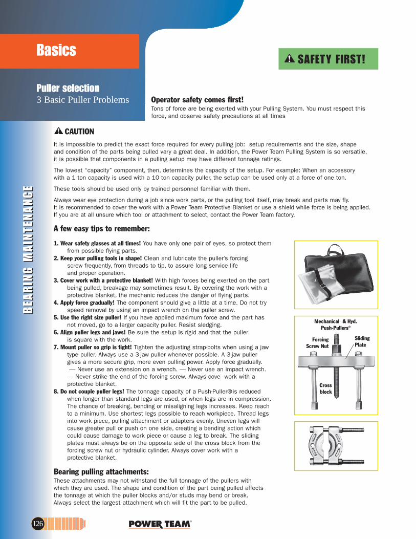
BEA
RIN
G M
AIN
TEN
AN
CE
BEA
RIN
G M
AIN
TEN
AN
CE
Puller selection3 Basic Puller Problems
Basics
126
Crossblock
SlidingPlate
ForcingScrew Nut
Mechanical & Hyd. Push-Pullers®
A few easy tips to remember:
1. Wear safety glasses at all times! You have only one pair of eyes, so protect them from possible flying parts.
2. Keep your pulling tools in shape! Clean and lubricate the puller’s forcing screw frequently, from threads to tip, to assure long service life and proper operation.
3. Cover work with a protective blanket! With high forces being exerted on the part being pulled, breakage may sometimes result. By covering the work with a protective blanket, the mechanic reduces the danger of flying parts.
4. Apply force gradually! The component should give a little at a time. Do not try speed removal by using an impact wrench on the puller screw.
5. Use the right size puller! If you have applied maximum force and the part has not moved, go to a larger capacity puller. Resist sledging.
6. Align puller legs and jaws! Be sure the setup is rigid and that the puller is square with the work.
7. Mount puller so grip is tight! Tighten the adjusting strap-bolts when using a jaw type puller. Always use a 3-jaw puller whenever possible. A 3-jaw puller gives a more secure grip, more even pulling power. Apply force gradually.— Never use an extension on a wrench. — Never use an impact wrench.
— Never strike the end of the forcing screw. Always cove work with a protective blanket.
8. Do not couple puller legs! The tonnage capacity of a Push-Puller®is reduced when longer than standard legs are used, or when legs are in compression. The chance of breaking, bending or misaligning legs increases. Keep reach to a minimum. Use shortest legs possible to reach workpiece. Thread legs into work piece, pulling attachment or adapters evenly. Uneven legs will cause greater pull or push on one side, creating a bending action which could cause damage to work piece or cause a leg to break. The sliding plates must always be on the opposite side of the cross block from the forcing screw nut or hydraulic cylinder. Always cover work with a protective blanket.
Bearing pulling attachments:These attachments may not withstand the full tonnage of the pullers with which they are used. The shape and condition of the part being pulled affectsthe tonnage at which the puller blocks and/or studs may bend or break. Always select the largest attachment which will fit the part to be pulled.
CAUTIONIt is impossible to predict the exact force required for every pulling job: setup requirements and the size, shape and condition of the parts being pulled vary a great deal. In addition, the Power Team Pulling System is so versatile,it is possible that components in a pulling setup may have different tonnage ratings.
The lowest “capacity” component, then, determines the capacity of the setup. For example: When an accessory with a 1 ton capacity is used with a 10 ton capacity puller, the setup can be used only at a force of one ton.
These tools should be used only by trained personnel familiar with them.
Always wear eye protection during a job since work parts, or the pulling tool itself, may break and parts may fly. It is recommended to cover the work with a Power Team Protective Blanket or use a shield while force is being applied. If you are at all unsure which tool or attachment to select, contact the Power Team factory.
Operator safety comes first!Tons of force are being exerted with your Pulling System. You must respect thisforce, and observe safety precautions at all times
SAFETY FIRST!

BEA
RIN
G M
AIN
TENA
NC
EB
EAR
ING
MA
INTEN
AN
CE
1-25 Ton2 & 2/3 Jaw Pullers
Mechanical JAW PULLERS
www.powerteam.com 127
Pullers designed to pull gears,bearings and countless otherpress fitted parts.
Pulling attachment
Step plate
Shaft protector
• Grip-O-Matic® feature on allpullers. The harder the pull,the tighter the grip for removinggears, bearings and countlessother press fitted parts.
• 2-way, 3-way and 2/3 waycombination pullers make it easyto select a specific puller for aspecific application.
• Forged from high quality steel,heat treated and subjected to rigorous tests which exceed rated puller capacity.
• Alloy steel heads are forged formaximum strength.
• Forcing screw threads are rolled,not cut. This process creates asmoother and stronger thread.
• Heat treated alloy steel crossbolts for maximum shear strength.
• Machined puller jaw toes producelarger and stronger pulling toes.
Choosing the right size puller: Compare the “reach” and “spread” of the pulling job with that of the pullers listed. The puller selected must have dimensions greater than those of the job.
Rea
ch
Spread
Reach
Jaw width
Rea
ch
Reach
SpreadJaw thickness
2/3-jawcombination
3-jawhead
2-jawhead
Styles of puller cross heads
Fed. Spec.: GGG-P-00781-D
• For puller piece part identification, consult factory. • Available standard 17.5 ton & 25 ton mechanical jaw pullers, consult factory.
waJ.xaMOrder Reach Spread Screw Size Thickness Width Capacity,No. (mm) (mm) (in.) (mm) (mm) Style and Weight
1020 54 82,6 5/16–24 x 98,4 mm 3,5 6,4 1-Ton, 2-Jaw;
0,14 kg1021 54 82,6 5/16–24 x 98,4 mm 3,5 6,4 1-Ton, 3-Jaw;
0,23 kg1022 85,7 101,6 3/8–24 x 124 mm Upper 4,8 Upper 6,4 2-ton, 2-Jaw; 0,4 kg
Lower 3,2 Lower 12,7 (Reversible Jaws)1023 85,7 121 3/8–24 x 124 mm Upper 4,8 Upper 6,4 2-ton, 2/3-Jaw; 0,6 kg
Lower 3,2 Lower 12,7 (Reversible Jaws)1024 83 152 9/16–20 x 176 mm Upper7,9 Upper 9,5 5-Ton, 2-Jaw; 0,8 kg
Lower 6,4 Lower 19,1 (Reversible Jaws)1026 83 178 9/16–20 x 176 mm Upper 7,9 Upper 9,5 5-Ton, 2/3-Jaw; 1,3 kg
Lower 6,4 Lower 19,1 (Reversible Jaws)1025 140 152 9/16–20 x 176 mm Upper7,9 Upper 9,5 5-Ton, Long 2-Jaw;
Lower 6,4 Lower 19,1 (Reversible Jaws) 0,9 kg1027 140 178 9/16–20 x 178 mm Upper 7,9 Upper 9,5 5-Ton, Long 2/3-Jaw;
Lower 6,4 Lower 19,1 (Rev. Jaws) 1,5 kg1035 127 229 11/16–18 x 229 mm Upper7,9 Upper 25,4 7-Ton, 2-Jaw;
Lower 8,7 Lower 25,4 (Reversible Jaws) 2 kg1037 127 267 11/16–18 x 229 mm Upper 7,9 Upper 25,4 7-Ton, 2/3-Jaw;
Lower 8,7 Lower 25,4 (Rev. Jaws) 2,8 kg1036 222 241 11/16–18 x 229 mm 8,7 25,4 7-Ton, Long 2-Jaw;
2,3 kg 1038 222 279 11/16–18 x 229 mm 8,7 25,4 7-Ton, Long 2/3-Jaw;
3,3 kg1039 279 318 13/16–16 x 305 mm 14,3 25,4 13-Ton, 2-Jaw;
4,8 kg1040 387 279 13/16–16 x 305 mm 14,3 25,4 13-Ton, Long 2-Jaw;
5,9 kg1041 279 356 13/16–16 x 305 mm 14,3 25,4 13-Ton, 2/3-Jaw;
6,7 kg1042 387 432 13/16–16 x 305 mm 14,3 25,4 13-Ton, Long 2/3-Jaw;
8,3 kg
1020 1021
1022 1023
1024 1026
1025 1027
1035 1037
1041/10421039/1040
1036 1038

BEA
RIN
G M
AIN
TEN
AN
CE
BEA
RIN
G M
AIN
TEN
AN
CE
10, 171/ 2, & 30 Ton Cap.
MechanicalPUSH PULLERS
For removing and installinggears, bearings, pulleys andother press-fitted parts.
PushingForce
PullingForce
PushingForce
SlidingPlate
Nut
PullingForce
PushingForcePulling
Force
Sliding Plate
ASSEMBLING THE TOOL TO APPLY PUSHING OR PULLING FORCE:1. Determine if you want the tool’s forcing
screw to push or pull. 2. To exert pushing force, the forcing nut is
installed beneath the cross block, as shown on left.
3. To cause the forcing screw to pull,the forcing nut is placed on top of the cross block.
4. The slididng plates must always be placed on the opposite side of the cross block from the forcing nut.
Selection and capacity rating –
Each Push-Puller’s specified tonnage “capacity” is determined using its standardlegs in tension. Using longer legs, or a setup in which the legs are in compression, willreduce the “capacity”. Always select thelargest “capacity” puller and the shortest legs that will fit the job.
Bearing PullingAttachment
Internal PullingAttachment
Nut
939 Max.Reach Spread Screw Size Notes / Weight
267 mm 178–413 mm 11/2"–12 x 438 mm Leg ends threaded 1"–14. No. 1109 legs and No. 28390 leg ends included. Wt., 20 kg
938 Max.Reach Spread Screw Size Notes / Weight
282 mm 79–298 mm 1"–14 x 336 mm Leg ends threaded 5/8"–18. No. 1106 legs and No. 24827 leg endsincluded. Wt., 9,4 kg
.tW & htgneL geL.oN redrO.tW & htgneL geL.oN redrO1107 114 mm 1105 572 mm
gk 1,4gk 1,11106* 241 mm 1108 762 mm
gk 2,5gk 21104 419 mm
3kg
939
Extra Legs (pair) for No. 939 Push-Puller (Reach equals leg length plus 66,7 mm with leg end caps.)Spread
Reach
Extra Legs (pair) for No. 938 Push-Puller (Reach equals leg length plus 50,8 mm with leg end caps.)
Extra Legs (pair) for No. 927 Push-Puller (Reach equals leg length plus 50,8 mm with leg end caps.)
927 Max.Reach Spread Screw Size Notes / Weight
210 mm 54 - 184 mm 3/4"–16 x 305 mm 1/2" of forcing screw tip end is threaded 5/8"–18. No. 1100 legsand No. 24827 leg ends included. Wt., 3,2 kg.
.tW & htgneL geL.oN redrO.tW & htgneL geL.oN redrO1103 121 mm, 1102 298 mm,
gk 1gk 54,01100* 171 mm, 1101 400 mm,
gk 5,1gk 7,0
927
Spread
938
Spread
.tW & htgneL geL.oN redrO.tW & htgneL geL.oN redrO1109* 203 mm 1111 711 mm
gk 01gk 6,31110 457 mm
6,8 kg
* Standard legs (pair) with pullers.
No. 927 – 10-Ton Capacity can be used with No. 1123bearing pulling attachment or No. 679 pulley pulling attachment. May also be used with Nos. 1150, 1151,1152, or 1153 internal pulling attachments.
No. 938 – 171/2-Ton Capacity can be used with Nos. 1124and 1130 bearing pulling attachment or Nos. 679 and 680 pulley pulling attachment. May also be used with Nos. 1150, 1151, 1153, or 1166 internal pulling attachments.
No. 939 – 30-Ton Capacity can be used with Nos. 1126and 1127 bearing pulling attachment or No. 680 pulleypulling attachment (two 8012 adapters are required to connect 680 to puller). Can be used with No. 1165internal pulling attachments.
128

www.powerteam.com
BEA
RIN
G M
AIN
TENA
NC
EB
EAR
ING
MA
INTEN
AN
CE
Jaw SpreadsBearing & Pulley
PullingATTACHMENTS
CAUTION – These attachments may not withstand the full tonnage of the pullers theyare used with. The shape and condition of the part being pulled affects the tonnage atwhich the jaws may slip off. Always select the largest attachment which will fit behind
• Handles internal pulling jobs, such as, bearing /bearing cup removal, bushing removal,oil seals, etc.
• Remove hard to get at parts easily and without damage!
• Use with corresponding Power Team SlideHammer or Push-Puller.®
• Adjustable jaws fit various diameters
Fed. Spec.: GGG-P-00781-D
A
B
JawOrder Spread Reach A B Wt.No. (mm) (mm) (in. – thd.) (in. – thd.) (kg) Application
1153 38,1–127 54 1–14 5/8–18 1,9 Use with Nos. 927 and 938 Push-Pullers,1150 38,1–152 102 1–14 5/8–18 21151 38,1–178 133 1–14 5/8–18 21152 38,1–152 102 – 5/8–18 1,6 Use with Nos. 927 and 938 Push-Pullers, 1155 and 1156
slide hammer pullers, or 24832 and 24833 puller screw.1154 38,1–152 102 1–8 5/8–18 2 Use with No. PPH17.1165 76,7–229 149 11/2–12 1–14 6,1 Use with No. 939 Push-Puller.1166 76,2–229 149 11/4–7 1–14 6,1 Use with No. PPH30.
Puller Screws24832 349 mm long 5/8 .3511 dna,2511,1511,0511 .soN htiw esU5,081–24833 140 mm long 5/8 .3511 dna,2511,0511 .soN htiw esU2,081–
Reach
Spread
X
Y
Max.Order Spread X Y A B C D E Wt.No. (mm) (in.) (mm) (mm) (mm) (mm) (mm) (mm) (kg) Application - (Use with Puller Nos.)
1121 6,4-22,2 5/16–18 43 11,1 3,2 12,7 34,9 50,8 0,3 1020, 1022, and 1023.
1122 3,2-51 3/8–16 62 11,1 4,0 15,9 50,8 69,9 0,6 1024, 1025, 1026, 1027, 7392 and 7393.
1123 9,5-117 5/8–18 111 22,2 9,5 25,4 88,9 114,3 2.3 1035, 1036, 1037, 1038, and 927.
1124 12,7-133 5/8–18 152 34,9 11,1 31,8 127 158,8 5,4 1039, 1040, 1041, 1042, PH172, PPH17, and 938.
1126 16-203 1–14 181 34,9 17,5 34,9 146,1 190,5 9 1047, 1043, and 939.1127 19-340 1–14 260 44,5 17,5 44,5 158,8 215,9 18,8 1047, 1073, and 939.1128 127-327 13/4–12 330 44,5 19,1 57,2 327 406 45,4 PH553C, and PPH50. (When using 1128 with PPH50, two
8024 adapters are required to connect PPH50 to the puller tees.) 1130 12,7-219 5/8–18 152 34,9 11,1 31,8 127 158,8 5,4 1039, 1040, 1041, 1042, PH172, PPH17, and 938.
V-belt pulley pulling attachments679 45-149 5/8 .729 dna,8301,7301,6301,5301225181–
680 42,3-254 5/8 03HPP,271HP,7401,2401,1401,0401,93011,0175281– * and 938.
(When using 680 with PPH30, two 8012 adapters are required.)
• “Knife-like” edges fit behind bearings and other hard-to-grip partsfor easy removal, even where clearance is limited.
• Usable with both Grip-O-Matic® jawtype pullers and Push-Pullers®.
• All puller blocks are made fromforged alloy steel.
Fed. Spec.: GGG-P-00781-D
• 24832 & 24833 acts as a regular forcing screw when threaded directly into block of pulling attachment.
X = Thread of tapped hole in adapter.
Y = Distance between adjusting screws.
Attachment clamps down into V-groove to distributeload. Use with Grip-O-Matic® pullers or Push-Pullers.
Crosssection
“Knife-like” edges
Flat back surface
E
DB
C
A
atminspread
atminspread
129
the part being pulled (See page 126).
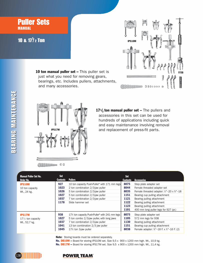
BEA
RIN
G M
AIN
TEN
AN
CE
BEA
RIN
G M
AIN
TEN
AN
CE
10 & 171/ 2 Ton
Puller SetsMANUAL
IPS17M
IPS10M
Note: Storing boards must be ordered separately.No. DB10M – Board for storing IPS10M set. Size 9,5 x 900 x 1200 mm high. Wt., 10,9 kg.No. DB17M – Board for storing IPS17M set. Size 9,5 x 900 x 1200 mm high. Wt., 11,4 kg.
Step plate adapter set572 mm legs for 938Bearing pulling attachmentBearing cup pulling attachmentFemale adapter: 5⁄8"–18 F. x 3⁄4"–16 F. (2)
171⁄2 ton capacity Push-Puller® with 241 mm legs5 ton combo 2/3-jaw puller, with long jaws7 ton combination 2/3-jaw puller13 ton combination 2/3 jaw puller171⁄2 ton 3-jaw puller
IPS17M171/2 ton capacity Wt., 52,7 kg.
SetContents Accessories
Step plate adapter setFemale threaded adapter setFemale threaded adapter: 1⁄2"–20 x 5⁄8"–18Bearing cup pulling attachmentBearing pulling attachmentBearing pulling attachment Bearing pulling attachment400 mm long puller legs for 927 (pr.)
SetContents Pullers
10 ton capacity Push-Puller® with 171 mm legs2 ton combination 2/3-jaw puller 5 ton combination 2/3-jaw puller 5 ton combination 2/3-jaw puller 7 ton combination 2/3-jaw puller
80751105113011518038
9381027103710411045
80758044803511511121112211231101
92710231026102710371178 Slide hammer set
Manual Puller Set No.Order No.IPS10M10 ton capacity Wt., 24 kg.
171/2 ton manual puller set – The pullers and accessories in this set can be used for hundreds of applications including quick and easy maintenance involving removal and replacement of press-fit parts.
10 ton manual puller set – This puller set is just what you need for removing gears,bearings, etc. Includes pullers, attachments,and many accessories.
130

www.powerteam.com
BEA
RIN
G M
AIN
TENA
NC
EB
EAR
ING
MA
INTEN
AN
CE
Specialty Pullers & Metric
Adapters
A
B
Note: All adapters available separately. *Not included in set No. 8044. Order separately.
Order Female FemaleNo. End “A”
8040 5/8"–18 1"–148041 5/8"–18 11/8"–128042 5/8"–18 11/4"–128043* 5/8"–18 11/2"–12
Order Female Female No. End “A” End “B”
8035* 1/2"–20 5/8"–188036* 1"–14 1"–148037 5/8"–18 5/8"–188038 5/8"–18 3/4"–168039 5/8"–18 7/8"–14
• Female threaded adapters - Use these adapters on the ends of Push-Puller®
forcing screws, legs, or slide hammers in the removal and installation of shafts,axles, and housings.
Set No. 8044 – consists of a set of 6 adapters (Nos. 8037-8042)
Note: Nos. 8000–8029 – each sold individually.
Order Female Male LengthNo. End End (mm)
8015 5/8"–18 3/4"–10 57,28016 1"–14 3/4"–10 63,58017 5/8"–18 7/8"–14 57,28018 5/8"–18 7/8"–9 57,28019 5/8"–18 1"–14 57,28020 1"–8 5/8"–18 76,28021 1"–8 1"–14 76,28022 5/8"–18 1/8" pipe 57,28023 11/4"–12 1"–14 114,38024 11/4"–12 13/4"–12 114,38025 11/4"–7 5/8"–18 101,68027 11/4"–7 1"–14 101,68028 15/8"–51/2 1"–8 101,68029 15/8"–51/2 1"–14 101,6
Order Female Male LengthNo. End End (mm)
8000 5/8"–18 1/4"–20 57,28001 5/8"–18 5/16"–18 57,28002 5/8"–18 7/16"–14 57,28003 5/8"–18 7/16"–20 57,28004 5/8"–18 3/8"–24 57,28005 5/8"–18 3/8"–16 57,28006 5/8"–18 1/2"–20 57,28007 5/8"–18 1/2"–13 57,28008 5/8"–18 9/16"–18 57,28009 5/8"–18 9/16"–12 57,28010 5/8"–18 5/8"–11 57,28011 1"–14 5/16"–11 63,58012 1"–14 5/8"–18 818013 5/8"–18 3/4"–16 57,28014 1"–14 3/4"–16 63,5
• Male-female threaded adapters – These adapters are used on ends of Push-Puller® legs, with forcing screws or slide hammers to assist in pulling shafts, bearing caps, pinions, and many other parts.
Fed. Spec.: GGG-P-00781-D
A
B
Order Dia.“A” Dia.“B”No. (mm) (mm)
8068 66,5 53,88069 69,9 57,28070 72,9 60,38071 76,2 63,58072 82,6 69,98073 88,9 76,2
Set No. 8076
Order Dia.“A” Dia.“B”No. (mm) (mm)
8063 47,5 38,18064 50,8 41,18065 53,8 44,58066 60,2 47,58067 63,5 50,8
Set No. 8075
Order Dia.“A” Dia.“B”No. (mm) (mm)
8057 25,4 19,18058 28,4 22,18059 31,8 25,48060 34,8 28,48061 41,1 31,88062 44,5 34,8
Set No. 8075
“C” “D”Order “A” “B” (60°) (60°)No. (mm) (mm) (mm) (mm)
8053 19,1 19,1 6,4 6,48054 15,7 15,7 6,4 6,48055 15,7 15,7 4,8 4,8
CAUTION: All the items shown may not withstand the full tonnage of the pullers they may be used with (Refer page 126).
“C” “D”Order “A” “B” (60°) (60°)No. (mm) (mm) (mm) (mm)8050 38,1 19,1 9,4 11,18051 31,8 19,1 9,4 9,48052 25,4 19,1 9,4 7,9
• Shaft protector set -- Power Team shaft protectors are designed to protect shaft centers from distortion when extreme pressures are applied with jaw-type pullers or Push-Pullers®. Shaft protectors are inserted between the end of the puller screw and the shaft.
Set No. 8056 – Set of 6 shaft protectors (Nos. 8050 thru 8055).
• Step plate adapter sets – Power Team step plate adapters are necessary for pulling and installing bearings, gears,or other parts on hollow shafts or housings. Puller screw forces against step plate adapter, as shown at right. May be used with Power Team jaw-type pullers, Push-Pullers® and shop presses.
Set No. 8075 – set of 11 adapters (Nos. 8057-8067). Set No. 8076 – set of 6 adapters (Nos. 8068-8073).
131

BEA
RIN
G M
AIN
TEN
AN
CE
BEA
RIN
G M
AIN
TEN
AN
CE
PullersSLIDE HAMMER
132
Blind hole puller set – Removal ofbearings, bushings, sleeves and otherfriction-fitted parts from blind holes cannow be accomplished with ease. Setprovides selection of expanding collets8 to 44,5 mm I.D. Collet is placedthrough bore of part to be removed,then expanded with actuator pin so that lips of collet secure a positive grip for pulling. Pulling force is exerted by means of a forcing screw and bridge assembly or with a slide hammer.
No. 981 – Blind-hole puller set with slide hammer, forcing screw, bridge, actuatorpins, collets, and storage box. Wt., 9,5 kg.
Slide hammer puller set – This very handy set is ideal for those close-quarter, inside pulling jobs. Very practical for pulling motor, generator, and magneto bearings. Also good for removing small-bore bushings, bearings, and oil seals.No. SS2 – Slide hammer puller set. Wt., 2,6 kg.
Slide hammer puller set – This useful set contains a reversible-jaw slide hammer puller with a 1,1 kg sliding hammer plus an assortment of special jaws (3 of each size) and adapters. In this set, you get all the versatility you demand of a slide hammer puller.No. 1178 – Slide hammer puller set with 1,1 kg. sliding hammer. Wt., 6,3 kg.
Sliding hammers only -
No. 22185 – 1,1 kg sliding hammer.
No. 34331 – 2,3 kg sliding hammer.
blind hole puller example
76,2mm441953469832054 50,8mm32mm
114mm
44148 1156
2724127315 36578
22185 34331
2-Jaw Spread 3-Jaw Spread Inside Outside Inside Outside Jaw Min. Max. Min. Max. Min. Max. Min. Max. (mm) (mm) (mm) (mm) (mm) (mm) (mm) (mm) 44195 38,1 114,3 19,1 127 38,1 120,7 25,4 114
32054 19,1 60.3 — — 25,4 69.9 — —
44148 69,9 139.7 19,1 191 82,6 158,8 25,4 159 34698 31,8 88,9 25,4 114 38,1 108 38,1 114
*Use with 3 mm actuator pin. **Use with 4,8 mm actuator pin. ***Use with 12,7 mm actuator pin
Order No. Inch Range MM Range Order No. Inc Range MM Range
33856* 5/16” to 3/8” 8 to 9.5 33861** 3/4” to 7/8” 19.1 to 22.2 33857* 3/8” to 7/16” 9.5 to 11.1 33862** 7/8” to 1” 22.2 to 25.4 33858** 7/16” to 1/2” 11.1 to 12.7 33863*** 1” to 11/4” 25.4 to 31.7 33859** 1/2” to 5/8” 12.7 to 15.9 33864** 11/4” to 11/2” 31.7 to 38.1 33860** 5/8” to 3/4” 15.9 to 19.1 33865*** 11/2” to 13/4 38.1 to 44.4
Order No. Description Order No. Description
24835 Forcing Screw 28253 Actuator Pin (5 mm dia.) 24836 Forcing Screw Nut 28256 Actuator Pin (12,7 mm dia.) 22185 Hammer 1,1 kg. 41331 Bridge 208627 Shank & Tee Bar Assembly 28323GY8 Metal Box 28250 Actuator Pin (3,2 mm dia.) 10419 Metal Box
daerpS edisnI .xaM .niM waJ )mm( )mm( teS
1172 8,05 7,21
1174 9,43 7,21
Set No. 981

www.powerteam.com 133
BEA
RIN
G M
AIN
TENA
NC
EB
EAR
ING
MA
INTEN
AN
CE
1158
Reach Spread Spread Prod. Overall Order Max. Min. Max. Wt. Length No. (mm) (mm) (mm) (kg) (mm)
1157 102 38,1 152 4,5 711 1158 102 38,1 152 5,6 711
7136
Slide hammer pullers with cup pulling attachments – These combine a basic slide hammer with No. 1152 internal pulling attachment for removing oil seals, outer races, and bearing cups from blind holes.No. 1157 – Slide hammer puller consisting of 1156 slide hammer and 1152 internal pulling attachment. No. 1158 – Same as 1157 but with 1155 slide hammer.
1155
1156
Special slide hammer puller – Ideal for
pulling jobs in very close quarters, as in
removal of small-bore bushings,
bearings, oil seals, etc. Internal pulling
attachment has jaw spread of 12,7 to 35 mm. Handle end has a 1/2”– 20 thread.
No. 1173 – Slide hammer puller. Wt., 1,6 kg.
No. 1174 – Puller head, less slide hammer.Basic slide hammer units – Compatible with internal pulling attachment (see page 198). Compatible with threaded adapters (see page 204-205). 610 mm length, 5/8”–18 threaded end.
No. 1155 – Basic slide hammer unit with 2,3 kg hammer. Wt., 3,3 kg.No. 1156 – Basic slide hammer unit with 1,1 kg hammer. Wt., 2,2 kg.
Reversible-jaw slide hammer pullers – Ideal for pulling gears, bearings, outer races, grease retainers, oil seals, etc. Two or three jaws may be used and positioned for “inside” or “outside” pulling jobs. Both have 5/8”– 18 threaded end so attachments and adapters may be used.No. 1176 – Slide hammer puller with 1,1 kg hammer, 27241 two-way head and
34698 jaws. Wt., 3,3 kgNo. 1177 – Same as 1176 but with 2,2 kg hammer. Wt., 4,8 kg
1173
daerpS waJ 3 daerpS waJ 2 Inside Outside Inside Outside Prod. Overall Order Min. Max. Min. Max. Min. Max. Min. Max. Wt. Length No. (mm) (mm) (mm) (mm) (mm) (mm) (mm) (mm) (kg) (mm)
1176 31,8 88,9 25,4 114 38,1 108 38,1 114 3,6 686
1177 31,8 88,9 25,4 114 38,1 108 38,1 114 4,8 686
1176
1177
2-JawSpread
3-JawSpread
JawsReversed
Bearing cup remover – The 7136 is perfect for pulling internal bearing cups, seals, bushings, etc. Jaw spread – 23,8 to 82,6 mm, reach to 88,9 mm.Use with any slide hammer having 5/8”-18 thread (Power Team 1155, 1156 or 927 Push-Puller®). No. 7136 – Universal bearing cup remover. Wt., 0,7 kg.Pilot bearing pullers -These very versatile pullers are built especially for inside pulling jobs, and particularly for removing flywheel pilot bearings on machines and construction vehicles. Also very practical for pulling motor, generator and magneto bearings.
1170
I.D. Spread Order Reach Min. Max. Wt.
No. (mm) (mm) (mm) (kg)
1170 19,1 12,7 38,1 2,2 1171 25,4 22,2 54 2,2 1172 44,5 12,7 50,8 2,2

BEA
RIN
G M
AIN
TEN
AN
CE
BEA
RIN
G M
AIN
TEN
AN
CE
6 - 30 Ton
Hydra Grip-O-Matic®
USE WITH 2/3 JAW PULLERS
PH63C
DE
F
PH82K
* PH303C include protective blanket & storage case
Reac
h
Stro
ke
Spread
Cyl. Order Reach Min. Max. SpreadCap. No. Studs Jaws Reach Studs Jaws Stroke A B C D E F Wt.
(tons) (mm) (mm) (mm) (mm) (mm) (mm) (mm) (mm) (mm) (mm) (mm) (in.) (kg)
6 PH63C –– 152 –– –– 200 80 11 6,4 22 83 22 — 4,98 PH83C –– 190 –– — 249 80 11 9,5 25,4 83 22 –– 6,611 PH113C — 229 –– — 280 80 14,3 9,5 29 83 29 –– 8,030 * PH303C — 375 –– — 540 110 27 36.5 38 170 54 –– 32.38 PH82K 266,7 207 125 300 245 80 52 25,4 16 83 22 5/8-18 UNF 9,5
11 HST11S — 150 –– — 102-410 80 — — — 65 29 — 14,5
• You get the world’s most copied puller design; the harder the pulling force,the tighter the jaws grip for secure holding force.
• Power Team pullers are tested for top performance and reliability at maximum capacity and jaw spread.
• Removing a wide variety of gears,bearings, bushings, pulleys and other press-fitted parts becomes a routine task.
• Easily metered release valve control knob.
• Spring loaded live centering cone.• Bladder type oil reservoir.• Rapid adjustment.• Use with 2 or 3 jaws.• Supplied with a sturdy storage/
carrying case.• Features Power Team’s exclusive
Marathon Limited Lifetime Warranty.
Hydra Grip-O-Matic® pulling system - These pullers are ideal for pulling a wide variety of press-fitted parts including bushings, bearings, wheels,gears and pulleys. Applications can be found in a wide variety of industries as well. Grip-O-Matic® pullers have been rigorously tested for top performance and reliability. PH82K is a complete pulling system which includes a hydraulic power module, 2-way puller head, jaws, legs and bearing splitter attachment; all contained in a convenient carrying case.
A self contained pulling system in a compact package
134
PH303C

www.powerteam.com
BEA
RIN
G M
AIN
TENA
NC
EB
EAR
ING
MA
INTEN
AN
CE
Accessories
Puller
K82
1188
K83
HST11
Shaft adapterincluded
Puller Accessory converts PH113C into a Hydraulic Straightening Tool – Portable...Good for straightening mechanical shafts, round bars, etc. Simply remove pump and cylinder from puller head and insert them into the straightening tool accessory. This product is widely used in steel mills, wire roll companies, wire extruding companies, textile industry, and any straightening situation where portability and power are required. Contoured heat-treated shaft adapter included.
No. HST11 – Spread: 89 to 410 mm, Reach: 150 mm. Wt., 9,5 kg.
Long jaw set for PH83C and PH113C Grip-O-Matic® pullers – This long jaw set is the perfect addition to the PH83C or PH113C Grip-O-Matic® hydraulic pullers. The extra long jaws give you the added capability of pulling a wider variety of parts. Jaw capacity is 8 tons when used with the PH83C puller; 11 tons when used with the PH113C puller.
No. 1188 – Spread: 280 to 317 mm, Reach: 317mm.
Hydra Grip-O-Matic® puller accessory kits – K82 accessory kit for the Hydra-Grip-O-Matic® puller No. PH83C. Includes 2-way puller head, 2 jaws,2 threaded legs and sturdy carrying/storage case.
No. K82 – Accessory kit for PH83C Grip-O-Matic® hydraulic puller. K83 2/3 way head accessories kit for a Hydra Grip-O-Matic® puller No. PH83C. Includes 2/3 way puller head, 3 jaws, 3 threaded legs and sturdy carrying/storage case.
No. K83 – Accessory kit for PH83C Grip-O-Matic® hydraulic puller.
135
HST11S
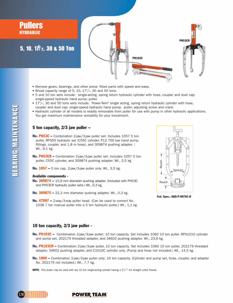
BEA
RIN
G M
AIN
TEN
AN
CE
BEA
RIN
G M
AIN
TEN
AN
CE
5, 10, 171/ 2, 30 & 50 Ton
PullersHYDRAULIC
PH53CR
PH103C
10 ton capacity, 2/3 jaw puller -
No. PH103C – Combination 2-jaw/3-jaw puller; 10 ton capacity. Set includes 1060 10 ton puller, RPS1010 cylinder and pump set, 202179 threaded adapter, and 34602 pushing adapter. Wt., 23,6 kg.
No. PH103CR – Combination 2-jaw/3-jaw puller, 10 ton capacity. Set includes 1060 10 ton puller, 202179 threaded adapter, 34602 pushing adapter, and C1010C cylinder only. (Pump and hose not included.) Wt., 14,5 kg.
No. 1060 – Combination 2-jaw/3-jaw puller only; 10 ton capacity. (Cylinder and pump set, hose, coupler, and adapter No. 202179 not included.) Wt., 7,7 kg.
NOTE: This puller may be used with any 10 ton single-acting cylinder having a 21/4"–14 straight collar thread.
5 ton capacity, 2/3 jaw puller –
No. PH53C – Combination 2-jaw/3-jaw puller set. Includes 1057 5 ton puller, RPS55 hydraulic set (C55C cylinder, P12 700 bar hand pump,fittings, coupler, and 1,8 m hose), and 309874 pushing adapter. |Wt., 9,1 kg.
No. PH53CR – Combination 2-jaw/3-jaw puller set. Includes 1057 5 ton puller, C55C cylinder, and 309874 pushing adapter. Wt., 5,5 kg
No. 1057 – 5 ton cap. 2-jaw/3-jaw puller only. Wt., 3,5 kg.
Available components - No. 309874 – 15,9 mm diameter pushing adapter. (Included with PH53C
and PH53CR hydraulic puller sets.) Wt., 0,3 kg.
No. 309875 – 22,2 mm diameter pushing adapter. Wt., 0,3 kg.
No. 47997 – 2-way/3-way puller head. (Can be used to convert No. 1038 7 ton manual puller into a 5 ton hydraulic puller.) Wt., 1,1 kg.
Reach
Spread
Rea
ch
• Remove gears, bearings, and other press- fitted parts with speed and ease.• Broad capacity range of 5, 10, 171/2, 30 and 50 tons.• 5 and 10 ton sets include: single-acting, spring return hydraulic cylinder with hose, coupler and dust cap;
single-speed hydraulic hand pump; puller.• 171/2, 30 and 50 tons sets include: Power-Twin® single acting, spring return hydraulic cylinder with hose,
coupler and dust cap; single-speed hydraulic hand pump; puller, adjusting screw and crank.• Hydraulic cylinder of all models is readily removable from puller for use with pump in other hydraulic applications.
You get maximum maintenance versatility for your investment.
Fed. Spec.: GGG-P-00781-D
136
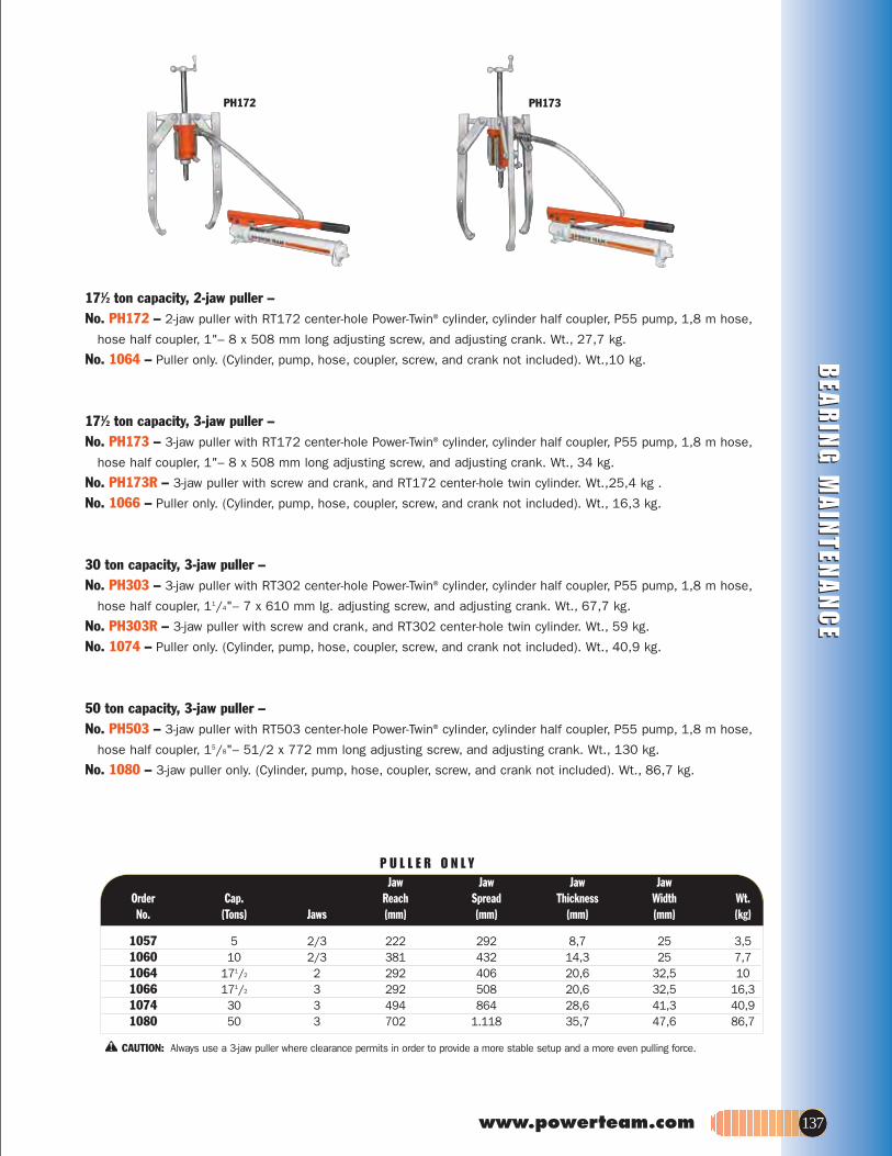
www.powerteam.com 137
BEA
RIN
G M
AIN
TENA
NC
EB
EAR
ING
MA
INTEN
AN
CE
PH172 PH173
Jaw Jaw Jaw Jaw.tWhtdiWssenkcihTdaerpShcaeR.paCredrO
No. (Tons) Jaws (mm) (mm) (mm) (mm) (kg)
1057 5 2/3 222 292 8,7 25 3,5 1060 10 2/3 381 432 14,3 25 7,71064 171/2 2 292 406 20,6 32,5 101066 171/2 3 292 508 20,6 32,5 16,31074 30 3 494 864 28,6 41,3 40,91080 50 3 702 1.118 35,7 47,6 86,7
P U L L E R O N L Y
CAUTION: Always use a 3-jaw puller where clearance permits in order to provide a more stable setup and a more even pulling force.
171⁄2 ton capacity, 2-jaw puller –No. PH172 – 2-jaw puller with RT172 center-hole Power-Twin® cylinder, cylinder half coupler, P55 pump, 1,8 m hose,
hose half coupler, 1"– 8 x 508 mm long adjusting screw, and adjusting crank. Wt., 27,7 kg.
No. 1064 – Puller only. (Cylinder, pump, hose, coupler, screw, and crank not included). Wt.,10 kg.
171⁄2 ton capacity, 3-jaw puller – No. PH173 – 3-jaw puller with RT172 center-hole Power-Twin® cylinder, cylinder half coupler, P55 pump, 1,8 m hose,
hose half coupler, 1"– 8 x 508 mm long adjusting screw, and adjusting crank. Wt., 34 kg.
No. PH173R – 3-jaw puller with screw and crank, and RT172 center-hole twin cylinder. Wt.,25,4 kg .
No. 1066 – Puller only. (Cylinder, pump, hose, coupler, screw, and crank not included). Wt., 16,3 kg.
30 ton capacity, 3-jaw puller – No. PH303 – 3-jaw puller with RT302 center-hole Power-Twin® cylinder, cylinder half coupler, P55 pump, 1,8 m hose,
hose half coupler, 11/4"– 7 x 610 mm lg. adjusting screw, and adjusting crank. Wt., 67,7 kg.
No. PH303R – 3-jaw puller with screw and crank, and RT302 center-hole twin cylinder. Wt., 59 kg.
No. 1074 – Puller only. (Cylinder, pump, hose, coupler, screw, and crank not included). Wt., 40,9 kg.
50 ton capacity, 3-jaw puller –No. PH503 – 3-jaw puller with RT503 center-hole Power-Twin® cylinder, cylinder half coupler, P55 pump, 1,8 m hose,
hose half coupler, 15/8"– 51/2 x 772 mm long adjusting screw, and adjusting crank. Wt., 130 kg.
No. 1080 – 3-jaw puller only. (Cylinder, pump, hose, coupler, screw, and crank not included). Wt., 86,7 kg.

BEA
RIN
G M
AIN
TEN
AN
CE
BEA
RIN
G M
AIN
TEN
AN
CE
The power to make impossiblejobs become routine.
171/ 2, 30-50 Ton
Push-Pullers®
HYDRAULIC
L
PushingForce
Cylinder
PullingForce
PushingForce
SlidingPlate
SlidingPlate
PullingForce
PushingForcePulling
Force
Cylinder
1105
572 mm4,1 kg
1104*
419 mm3 kg
1106
241 mm2 kg
1107
114 mm1,1 kg
Leg Ends – Upper leg ends arethreaded 3/4"-16. Lower leg endsare threaded 5/8"-18 x 25 mm lg.
Spread146-298 mm
Reach
PPH17
Selection and capacity rating – Each Push-Puller’s specified tonnage “capacity” is determined using its standard legs in tension. Using longer legs, or a setup in which the legs are in compression, will reduce the “capacity”. Always select the largest “capacity” puller and the shortest legs that will fit the job.
Power Twin® cylinder – This unique center-hole cylinder powers each Push-Puller®. Puller screw runs right between the twin spring cylinder. A basic head allows you to change from a tapped hole to a plain hole by merely changing the head insert.
NOTE: L = leg length: 114; 241; 419; 572 and 762 mm subtract 124 mm from leg length to determine reach when using leg end caps.
1. Determine if you want the tool’sforcing screw to push or pull.
2. To exert pushing force, the forcing nut is installed beneaththe cross block, as shown on left.
3. To cause the forcing screw topull, the forcing nut is placed ontop of the cross block.
4. The sliding plates must alwaysbe placed on the opposite sideof the cross block from the forcing nut.
ASSEMBLING THE TOOL TO APPLY PUSHING OR PULLING FORCE:1108
762 mm5,2 kg
• Can apply a hydraulic pushing or pulling force, depending on how thepuller is set up.
• Each unit includes perfectly matched hydraulic components that can be detached from the Push-Puller® for other tasks requiring dependable Power Team power; assuring maximum return on your investment.
• Optional leg kits adapt your Push-Puller®
to extra long or extra short reach.• A wide variety of threaded adapters,
bearing pulling attachments and internalpulling attachments can be used in combination with our Push-Pullers®.
171/2 ton capacity Push-Puller® – No. PPH17 – Push-Puller® with RT172 center-hole Power Twin® cylinder,
cylinder half coupler, P55 pump, 9767 1,8 m. hose, 9798 hose half coupler, 419* mm legs, 24827 leg ends, 1"-8 x 508 mm lg. adjusting screw and adjusting crank. Wt., 26,8 kg.
No. PPH17R – Same as above, but without P55pump, 9767 1,8 m. hose and 9798 hose half coupler. Wt., 18,2 kg.
No. 1062 – Puller only. (Cylinder, pump, hose, coupler, screw and crank not included.) Wt., 9,1 kg.
USE WITH:Bearing pulling attachments: Nos. 1124 and 1130. Pulley pulling attachment: No. 679. Internal pulling attachment: No. 1154. Legs: Nos. 1104, 1105, 1106, 1107 and 1108 - Pair of legs for 171/2-ton “capacity” Push-Puller®.
* No. 1104 included in PPH17, PPH17R & 1062.
138

www.powerteam.com 139
BEA
RIN
G M
AIN
TENA
NC
EB
EAR
ING
MA
INTEN
AN
CE
L
L
Leg ends are threaded 1"-14 x32 mm lg.
711 mm10 kg
1111
457 mm6,8 kg
1110*
203 mm3,6 kg
1109
Leg ends are threaded 11/4"-12 x 44,5 mm lg.
11131112*
864 mm21,3 kg
610 mm15,4 kg
PPH50
Spread216- 521 mm
Reach
Note: L = leg length: 203,457 and 711 mm; subtract149 mm from leg length todetermine reach when usingleg end caps.
Spread178-413 mm
Reach
PPH30
30 ton capacity Push-Puller® - No. PPH30 – Push-Puller® with RT302
center-hole Power Twin® cylinder, cylinder half coupler, P55 pump, 9767 1,8 m. hose,9798 hose half coupler, 457* mm legs,28390 leg ends, 11/4"-7 x 610 mm lg.
adjusting screw and adjusting crank. Wt., 46,3 kg.
No. PPH30R – Same as above, but without P55 pump, 9767 1,8 m hose and 9798 hose half coupler. Wt., 37,2 kg.
No. 1070 – Puller only. (Cylinder, pump, hose,coupler, screw and crank not included.) Wt., 19,1 kg.
USE WITH:Bearing pulling attachments. No. 680 (Use two8012 adapters to connect to puller.) Pulley pulling attachment: No. 679. Internal pulling attachment: No. 1166. Legs: Nos. 1109, 1110 and 1111 - Pair of legsfor 30 ton “capacity” Push-Puller®.
50 ton capacity Push-Puller® - No. PPH50 – Push-Puller® with RT503 center-
hole Power Twin® cylinder, cylinder half coupler,P55 pump, 9767 1,8 m hose, 9798 hose half coupler, 610* mm legs, 15/8"-51/2 x 722 mm
lg. adjusting screw and adjusting crank. Wt., 91,3 kg.
No. PPH50R – Same as above, but without P55 pump, 9767 1,8 m hose and 9798 hose half coupler. Wt., 82,2 kg.
No. 1076 – Puller only. (Cylinder, pump, hose,coupler, screw and crank not included.) Wt., 48,1 kg.
USE WITH:Bearing pulling attachments: Nos. 1128
and 1129. Legs: Nos. 1112 and 1113 - Pair of legs for
50 ton “capacity” Push-Puller®. * No. 1112 included in PPH50, PPH50R & 1076.
* No. 1110 included in PPH30, PPH30R & 1070.

BEA
RIN
G M
AIN
TEN
AN
CE
BEA
RIN
G M
AIN
TEN
AN
CE
171/ 2, 30 & 50 Ton
Puller SetsHYDRAULIC
IPS17
IPS17H
Contents Accessories
Bearing cup pulling attach. Bearing pulling attachment572 mm legs (pr)Speed crankScrew capAdjusting screwPushing adapter2-jaw head for 1066
Threaded Adapters1" – 8 F. x 5/8" – 18 M. (1)5/8" – 8 F. x 3/4" – 16 F. (1)
Contents Hydraulics
Single-stage hydraulichand pump assembly171/2 ton cylinder withthreaded insert Hose half couplerHydraulic hose – 1,8 mTee adapter Pressure gauge
Pullers171/2 ton cap. Push-Pullerwith 419 mm legs171/2 ton 3-jaw hyd. puller
Wooden storage box No. 308435OR9 is includedwith the sets listed on thispage. 1.016L x 406 W x 406 mmD Metal storageboxes also available (Seepage 145).
Contents Accessories
Bearing cup pulling attachBearing pulling attachmentBearing pulling attachment Bearing pulling attachment
Threaded Adapters5/8" – 18 F. x 3/8" – 16 M. (2)5/8" – 18 F. x 1/2" – 20 M. (2)5/8" – 18 F. x 1/2" – 13 M. (2)5/8" – 18 F. x 5/8" – 11 M. (2)5/8" – 18 F. x 3/4" – 16 M. (2)5/8" – 18 F. x 3/4" – 10 M. (2)5/8" – 18 F. x 7/8" – 14 M. (2)5/8" – 18 F. x 7/8" – 9 M. (2)5/8" – 18 F. x 1" – 14 M. (2)1" – 8 F. x 5/8" – 18 M. (1)1" – 8 F. x 1" – 14 M. (1)Female threaded adapter set
V-belt pulley pulling attachmentSet of 6 shaft protectors (8050-8055)Set of 11 adaptors (8057-8067)
5/8" –18 F. x 3/4"–16 F. (2)
Contents Hydraulics
Single-stage hyd. handPump assembly171/2 ton cylinder with threaded insertHose half couplerHydraulic hose – 1,8 mTee adapterPressure gauge
Pullers171/2 ton cap. Push-Puller®
with 419 mm legs Speed crankAdjusting screwPushing adapter572 mm legs (pr)171/2 ton 3-jaw hyd. pullerCombination 2/3-jaw puller171/2 ton 2-jaw puller headPuller screwCombination 2/3-jaw pullerCombination 2/3-jaw puller
11541130110524814282283211820145441224
80208038
P55
RT172
9798976796709059
1062
1066
1154112211231130
800580068007801080138015801780188019802080218044
67980568075
8038
P55
RT172
9798976796709059
1062
248143211820192311051066102741224248321037104128228 Cylinder cap
171⁄2 ton hydraulic puller set - This set includes a 3-jaw puller and a Push-Puller®. Ideal for heavy duty applications; put this set to work wherever large gears, bearings, wheels, pulleys, etc. are found.
No. IPS17H – 171/2 ton capacity hydraulic puller set. Includes hydraulics, pullers, wooden storage box and accessories listed below. Wt., 62,2 kg.
No. DB17H – Board for storing IPS17H set. Must be ordered separately. Size 15,9 x 1.200 x 1.200 mm Wt., 13,6 kg.
171/2 ton hydraulic master puller sets – Having this Power Team puller set at your fingertips will not only reduce your downtime, but also increase your profits.
No. IPS17 – 171/2 ton capacity puller set. Includes hydraulics, pullers, wooden storage box and accessories listed below. Wt., 86,7 kg.
No. IPS17B – Puller set with MB5 metal box. Wt., 96,7 kg.
No. DB17 – Board for storing IPS17 set. Must be ordered separately. Size: 15,9 x 1.200 x 1.800 mm long. Wt., 30,9 kg.
CONTENTS OF SET NO. IPS17
CONTENTS OF SET NO. IPS17H
140

www.powerteam.com 141
BEA
RIN
G M
AIN
TENA
NC
EB
EAR
ING
MA
INTEN
AN
CE
IPS30H
IPS50H
No. Pullers
50 ton, 3-jaw hyd. puller2-way head for 108050 ton cap. hydraulic Push-Puller® with 610 mm legs864 mm legs for 1076Speed crankScrew capPushing adapterAdjusting screwAccessoriesBearing pulling attachment
No. Hydraulics
Single-stage hydraulic handpump assembly50 ton cylinder withthreaded insertHose half couplerHydraulic hose – 1,8 mTee adapterPressure gauge
Threaded Adapters11/4" – 12F. x 13/4" – 12M.
(2) 15/8" – 51/2 F. x 1" – 8M.15/8" – 51/2 F. x 1" – 14M.
Contents Pullers
30 ton, 3-jaw hyd. puller2-way head for 107430 ton cap. hydraulic Push-Puller® with 457 mm legs 711 mm legs for 1070Speed crankScrew capPushing adapterAdjusting screw
Contents Hydraulics
Single-stage hydraulic handpump assembly30 ton cylinder with threaded insertHose half couplerHydraulic hose – 1,8 mTee adapterPressure gauge
AccessoriesFemale threaded adapters1" – 14F. x 1" – 14F. (2)
Bearing cup pulling attach.
1080504491076
111329595282303475532698
1128
P55
RT503
9798976796709059
8024
80288029
1074412261070
111127198282293451034758
P55
RT302
9798976796709059
8036
11661127 Bearing pulling attachment
Note: Wooden storage box No. 3084380R9 is provided with the sets listed on this page. 1180L x 615H x 579D Metal storage boxes also available (See page 145).
CAUTION: All the items shown may not withstand the full tonnage specified. Example: When an accessory with a 1 ton capacity is used with a 7 ton puller, the setup can be used only at a force of 1 ton.
50 ton capacity puller set - For those really big jobs,this 50 ton puller set is what you need. Just think of the jobs you can do with a 50 ton hydraulic Push-Puller®, a 2-jaw and a 3-jaw puller, both with a 50 ton capacity. Of course, you also get many versatile accessories and attachments.
No. IPS50H – 50 ton capacity hydraulic maintenance puller set. Includes hydraulics, pullers, wooden storage box and accessories listed below. Wt., 261 kg.
30 ton capacity puller set – Just what you need for those big jobs. Not only do you get a 30 ton hydraulic Push-Puller®,you also get a 2-jaw and 3-jaw hydraulic puller. Plus, many popular accessories and the hardware to tackle the big jobs right away.
No. IPS30H – 30 ton capacity hydraulic maintenance puller set. Includes hydraulics, pullers, wooden storage box and accessories listed below. Wt., 150 kg.
No. DB30H – Board for storing IPS30H set. Must be ordered separately. Size 15,9 x 1.200 x 1.800 mm Wt., 35,4 kg.
CONTENTS OF SET NO. IPS30H
CONTENTS OF SET NO. IPS50H

BEA
RIN
G M
AIN
TEN
AN
CE
BEA
RIN
G M
AIN
TEN
AN
CE
171/ 2 & 30 Ton171/ 2 & 50 Ton
Puller SetsHYDRAULIC IPS3017
Note: Wooden storage box No. 3084360R9 is provided with this set. 1.016 L x 432 H x 610 mm D Metal storage boxes also available (See page 145).
No. Accessories
Special puller forcing screwStep plate adapter setStep plate adapter setShaft protector setPulley pulling attachmentPulley pulling attachmentBearing cup pulling attach.Bearing cup pulling attach.Bearing pulling attachmentBearing pulling attachmentBearing pulling attachmentBearing pulling attachment
Threaded Adapters5/8" – 18 F. x 3/8" – 16 M. (2)5/8" – 18 F. x 1/2" – 20 M. (2)5/8" – 18 F. x 1/2" – 13 M. (2)5/8" – 18 F. x 5/8" – 11 M. (2)1" – 14 F. x 5/8" – 18 M. (2)5/8" – 18 F. x 3/4" – 16 M. (2)5/8" – 18 F. x 3/4" – 10 M. (2)5/8" – 18 F. x 7/8" – 14 M. (2) 5/8" – 18 F. x 7/8" – 9 M. (2)5/8" – 18 F. x 1" – 14 M. (2)1" – 8 F. x 5/8" – 18 M. (1)1" – 8 F. x 1" – 14 M. (1)11/4" – 7 F. x 5/8" – 18 M. (2)11/4" – 7 F. x 1" – 14 M. (2)1" – 14 F. x 1" – 14 F. (2)5/8" – 18 F. x 3/4" – 16 F. (2)Female threaded adapter set
No. Hydraulics
Single-stage hyd. handpump assembly171/2 ton center-hole twincylinder w/ threaded insert30 ton center-hole twincylinder w/ threaded insertHose half couplerHydraulic hose – 1,8 mTee adapterPressure gauge
Pullers171/2 ton cap. hydraulicPush-Puller® w/419 mm legs30 ton cap. hydraulicPush-Puller® w/457 mm legs171/2 ton 3-jaw hyd. puller30 ton 3-jaw hyd. puller171/2 ton 2-jaw puller head30 ton 2-jaw puller headCombination 2/3-jaw pullerCombination 2/3-jaw pullerCombination 2/3-jaw pullerLong jaws (3) for 1037Long jaws (3) for 1041572 mm legs for 1062711 mm legs for 1070Speed crankSpeed crankScrew capCylinder capAdjusting screwAdjusting screwPushing adapter
24832807580768056679680115411661122112311261130
80058006800780108012801380158017801880198020802180258027803680388044
P55
RT172
RT302
9798976796709059
1062
1070
10661074412244122610271037104143892309021105111124814271982822928228321183475834510201923Pushing adapter
CAUTION: All the items shown may not withstand the full tonnage specified. Example: When an accessory with a 1 ton capacity is used with a 7 ton puller, the setup can be used only at a force of 1 ton.
2-jaw puller reachesthrough spokes ofgear to grip hub.Hand pump supplieshydraulic power.
Flexible coupler isremoved from electric motor shaft with 2-jaw puller.
Typical setup for removing sprocket drive pinion shaft. Puller screw is attachedto shaft by threadedadapter. Shaft is nowready to be pulled outhydraulically.
171/2 and 30 ton capacity puller sets – These heavy-duty maintenance sets will more than pay for themselves, especially in saving you costly damage to parts. This set lets you tackle hundreds of applications where pushing and pulling are required.
No. IPS3017 – 171/2 and 30 ton capacity manual and hydraulic puller
set. Includes hydraulics, pullers, and accessories listed below. Wt., 244 kg.
No. IPS3017B – Puller set with MB8 metal box. Wt., 256 kg.
CONTENTS OF SET NO. IPS3017
142

www.powerteam.com 143
BEA
RIN
G M
AIN
TENA
NC
EB
EAR
ING
MA
INTEN
AN
CE
IPS5017
Combination of 50 ton capacity Push-Puller and cup pulling attachment simplifies the removal of a final drive axle seal.
Note: Wooden storage box No. 3084360R9 is provided with this set. 1143 L x 572 H x 762 mm D Metal storage boxes also available (See page 145).
CAUTION: All the items shown may not withstand the full tonnage specified. Example: When an accessory with a 1 ton capacity is used with a 7 ton puller, the setup can be used only at a force of 1 ton.
No. Accessories
Step plate adapter setStep plate adapter setShaft protector setBearing cup pulling attach.Bearing cup pulling attach.Bearing pulling attachmentBearing pulling attachmentBearing pulling attachmentBearing pulling attachmentBearing pulling attachmentReducing adapter for 1166Hex nut; 3/4" – 16 (2)Short bolt
Threaded Adapters5/8" – 18 F. x 3/8" – 16 M. (2)5/8" – 18 F. x 1/2" – 20 M. (25/8" – 18 F. x 1/2" – 13 M. (2)5/8" – 18 F. x 5/8" – 11 M. (2)5/8" – 18 F. x 3/4" – 16 M. (2)5/8" – 18 F. x 3/4" – 10 M. (2)5/8" – 18 F. x 1" – 14 M. (2)1" – 8 F. x 5/8" – 18 M. (1)1" – 8 F. x 1" – 14 M. (1)11/4" – 12 F. x 1" – 14 M. (2)15/8" – 51/2 F. x 1" – 8 M. (1)15/8" – 51/2 F. x 1" – 14 M. (1)5/8" – 18 F. x 3/4" – 16 F. (1)Female threaded adapter set
No. Hydraulics
Single-stage hyd. handpump assembly171/2 ton center-hole twincylinder w/ threaded insert50 ton center-hole twincylinder w/ threaded insertHose half couplerHydraulic hose – 1,8 mTee adapterPressure gauge
Pullers171/2 ton cap. hydraulicPush-Puller® w/419 mm legs50 ton cap. hydraulicPush-Puller® w/610 mm legs171/2 ton 3-jaw hyd. puller50 ton 3-jaw hyd. puller171/2 ton 2-jaw puller head50 ton 2-jaw puller headCombination 2/3-jaw pullerCombination 2/3-jaw pullerCombination 2/3-jaw pullerLong jaws (3) for 1037Long jaws (3) for 1041572 mm legs for 1062864 mm legs for 1076Speed crankSpeed crankScrew capCylinder capAdjusting screwAdjusting screwPushing adapterPushing adapterGear and pulley puller
8075807680561154116611221123112611271130344791021524829
80058006800780108013801580198020802180238028802980388044
P55
RT172
RT503
9798976796709059
1062
1076
10661080412245044910271037104143892309021105111324814295952822828230321183269834755201923739224833 Forcing screw for 7392
3-jaw puller provides grip whilehydraulic hand pump provides power to push shaft from housing.Shaft protector is used on end ofpuller screw.
Hydraulically poweredPush-Puller removes drive wheel. Pulling attachment is used to provide gripping surface.
171⁄2 and 50 ton capacity puller sets – If your looking for a maintenance puller set that will handle a wide variety of applications, this is the one for you. The mechanical and hydraulic pullers and attachments are designed to handle most removing and installing jobs with a minimal amount of effort.
No. IPS5017 – 171/2 and 50 ton capacity manual and hydraulic puller set. Includes hydraulics, pullers, wooden storage box and accessories listed below. Wt., 405 kg.
No. IPS5017B – Puller set with MB16 metal box. Wt., 415 kg.
CONTENTS OF SET NO. IPS5017
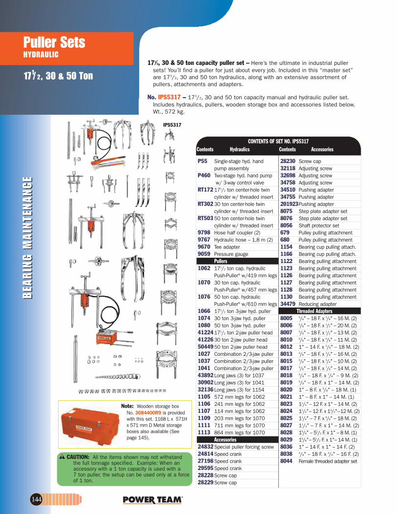
BEA
RIN
G M
AIN
TEN
AN
CE
BEA
RIN
G M
AIN
TEN
AN
CE
Puller SetsHYDRAULIC
171/ 2, 30 & 50 Ton
IPS5317
Note: Wooden storage box No. 3084400R9 is provided with this set. 1168 L x 571H x 571 mm D Metal storage boxes also available (See page 145).
Contents Accessories
Screw capAdjusting screwAdjusting screwAdjusting screwPushing adapterPushing adapterPushing adapterStep plate adapter setStep plate adapter setShaft protector setPulley pulling attachmentPulley pulling attachmentBearing cup pulling attach.Bearing cup pulling attach.Bearing pulling attachmentBearing pulling attachmentBearing pulling attachmentBearing pulling attachmentBearing pulling attachmentBearing pulling attachmentReducing adapter
Threaded Adapters5/8" – 18 F. x 3/8" – 16 M. (2)5/8" – 18 F. x 1/2" – 20 M. (2)5/8" – 18 F. x 1/2" – 13 M. (2)5/8" – 18 F. x 5/8" – 11 M. (2)1" – 14 F. x 5/8" – 18 M. (2)5/8" – 18 F. x 3/4" – 16 M. (2)5/8" – 18 F. x 3/4" – 10 M. (2)5/8" – 18 F. x 7/8" – 14 M. (2)5/8" – 18 F. x 7/8" – 9 M. (2)5/8" – 18 F. x 1" – 14 M. (2)1" – 8 F. x 5/8" – 18 M. (1)1" – 8 F. x 1" – 14 M. (1)11/4"– 12 F. x 1" – 14 M. (2)11/4"– 12 F. x 13/4"–12 M. (2)11/4" – 7 F. x 5/8" – 18 M. (2)11/4" – 7 F. x 1" – 14 M. (2)15/8" – 51/2 F. x 1" – 8 M. (1)15/8"– 51/2 F. x 1"– 14 M. (1)1" – 14 F. x 1" – 14 F. (2)5/8" – 18 F. x 3/4" – 16 F. (2)Female threaded adapter set
Contents Hydraulics
Single-stage hyd. handpump assemblyTwo-stage hyd. hand pumpw/ 3-way control valve
171/2 ton center-hole twincylinder w/ threaded insert30 ton center-hole twincylinder w/ threaded insert50 ton center-hole twincylinder w/ threaded insertHose half coupler (2)Hydraulic hose – 1,8 m (2)Tee adapterPressure gaugePullers171/2 ton cap. hydraulicPush-Puller® w/419 mm legs30 ton cap. hydraulicPush-Puller® w/457 mm legs50 ton cap. hydraulicPush-Puller® w/610 mm legs171/2 ton 3-jaw hyd. puller30 ton 3-jaw hyd. puller50 ton 3-jaw hyd. puller171/2 ton 2-jaw puller head30 ton 2-jaw puller head50 ton 2-jaw puller headCombination 2/3-jaw pullerCombination 2/3-jaw pullerCombination 2/3-jaw pullerLong jaws (3) for 1037Long jaws (3) for 1041Long jaws (3) for 1154572 mm legs for 1062241 mm legs for 1062114 mm legs for 1062203 mm legs for 1070711 mm legs for 1070864 mm legs for 1070AccessoriesSpecial puller forcing screwSpeed crankSpeed crankSpeed crankScrew cap
2823032118326983475834510347552019238075807680566796801154116611221123112611271128113034479
800580068007801080128013801580178018801980208021802380248025802780288029803680388044
P55
P460
RT172
RT302
RT503
9798976796709059
1062
1070
1076
106610741080412244122650449102710371041438923090232136110511061107110911111113
248322481427198295952822828229Screw cap
CAUTION: All the items shown may not withstand the full tonnage specified. Example: When an accessory with a 1 ton capacity is used with a 7 ton puller, the setup can be used only at a force of 1 ton.
171⁄2, 30 & 50 ton capacity puller set – Here’s the ultimate in industrial puller sets! You’ll find a puller for just about every job. Included in this “master set” are 171/2, 30 and 50 ton hydraulics, along with an extensive assortment of pullers, attachments and adapters.
No. IPS5317 – 171/2, 30 and 50 ton capacity manual and hydraulic puller set. Includes hydraulics, pullers, wooden storage box and accessories listed below. Wt., 572 kg.
CONTENTS OF SET NO. IPS5317
144

www.powerteam.com
Protective Blankets and Security Chests
BEA
RIN
G M
AIN
TENA
NC
EB
EAR
ING
MA
INTEN
AN
CE
PB1230C
MB16
A
B
CD
Order Size Number Wt.No. (mm) of Straps (kg)
PB1230C 305 x 762 2 1,3 508 x 914 2 1,9
PB2860 711 x 1.524 3 4,2PB3372C 838 x 1.829 3 5,3PB44120C 1.118 x 3.048 4 10,9PB51156C 1.295 x 3.962 4 15,5
egarotSsnoisnemiDOrder A B C D Cap. Wt. Optional No. (mm) (mm) (mm) (mm) (cu. m) (kg) Caster Wheels
MB5 883 356 813 483 0,14 30 No. 251646 – Set of four 102 mm casters (two swivel and MB8 1.010 483 1.670 483 0,25 40,9 two rigid). Furnished with mounting screws. Wt., 5,7 kg.
MB16 1264 610 1.219 610 0,45 57,2 No. 251647 – Set of four 152 mm casters (two swivel and two rigid). Furnished with mounting screws. Wt., 7 kg.
• Rugged, 16 gauge (1,6 mm) steel construction with fully arc welded seamsfor extra strength and weather protection.
• Full length piano hinges, mating cover to body, protect against weather and theft.
• Single or double latch security tabs for padlocks.• Mechanical cover supports, two 57 mm high skids.• Fold-down 19 mm pipe handles on each end of chest.• Pre-drilled for optional casters, which enhance mobility.• Durable baked enamel finish.
Job-site and maintenance security chests – Protect your valuable tools and equipment from theft and weather. When the day’s work is finished, you want to rest assured that your tools and equipment will be present the next day. In these times, security is a real concern. These rugged, lockable chests are the answer that many of our customers have been asking for.
Note: Custom sizes are available on a special order basis. Please consult factory.
Power Team protective blanket – Our blankets are designed to contain broken or lying parts from the most extreme forces, thus resulting in a much safer work environment.
Testing results – In our lab, this style of blanket held the parts of a necked-down grade 8 bolt, which shattered in a 100 ton center-hole hydraulic cylinder. The blanket sustained no visible damage when shot with a force and impact that shattered safety glasses!
• Effectively contain broken or flying parts from the most extreme pulling, pressing,pushing or stressing forces.
• Ideal for use with pullers and forcing presses.• Made of see-through, high-tensile, tear resistant material.• Unlike rigid, fixed guards, these blankets can be wrapped and strapped around
a job.• The clear protective blankets allow you to visually monitor the job from start
to finish.• Protective blankets come in a carrying/storage pounch to reduce aging caused
by prolonged exposure to light.
Protect yourself and your equipment.
PB2036CC
145

BEA
RIN
G M
AIN
TEN
AN
CE
BEA
RIN
G M
AIN
TEN
AN
CE
E N F O R C E R 5 5Hydraulic lift system for easy, precise position of puller.
Unique dual pump arrangement: Low pressure pump positions, holds and opens jaws. The high pressure pump advances and retracts the pushing cylinder without releasing clamped jaws.
Hydraulically-actuated jaws. Cylinder moves in or out to provide a safe, secure grip on workpiece.
Puller can be assembled in 2 or 3 jaw configurations.
Choice of cylinder with a 159 mm or 337 mm stroke.
Self-centering: Center cylinder on work; puller jaws will automatically grip work evenly.
Super Grip-O-Matic® feature means the harder the pull, the tighter the puller jaws grip. No chains or cages required to keep puller jaws from slipping or springing off the part being pulled.
Guards at pinch points protect operator.
Cart’s swivel casters give ease of mobility.
Large wheels make movement of cart easy.
Puller can be mounted on cart 90 degrees to right or left of puller cart centerline,permitting use in tight quarters, such as between machinery.
11
10
9
8
7
6
5
4
3
2
1
11
PH553C
2
3
7
8
9 10
1
45
6
Note: Four cylinder extensions (not pictured) are included. The included lifting eyes (not pictured) permit use of an overhead crane to raise entire assembly.
** Number of adapters supplied with each Enforcer.
Order A BNo. (mm) (mm) Qty.**
69,9 69,9 169,9 152,4 269,9 76,2 169,9 254 1
Reach Reach Puller Jaw Tip snoisnemiD.dorP.lyCllarevO .xaM.xaM.niM.niM
Order Spread Spread Spread Spread Length* Stroke Power Source Wt. A B CNo. (mm) (mm) (mm) (mm) (mm) (mm) Requirements (lbs.) (mm) (mm) (mm)
PH553C 101,6 559 1.219 356 2.286 159 115 V, 60Hz, 25 Amp Cap. 339 22 32 48PH553C13 101,6 381 1.219 178 2.286 337 115 V, 60Hz, 25 Amp Cap. 352PH553CL13* 63,5 651 1.149 559 2.591 337 115 V, 60Hz, 25 Amp Cap. 379PH553C-230 101,6 559 1.219 356 2.286 159 230 V, 50/60 Hz, 15 Amp Cap. 339PH553C13-230 101,6 381 1.219 178 2.286 337 230 V, 50/60 Hz, 15 Amp Cap. 352PH553CL-230* 63,5 829 1.149 737 2.591 159 230 V, 50/60 Hz, 15 Amp Cap. 366PH553CL13-230* 63,5 651 1.149 559 2.591 337 230 V, 50/60 Hz, 15 Amp Cap. 379
Note: Cart and Puller (cart width is 813 mm)
Pushing Adapters
converts PH553C series to PH553CL series. Jaws are 305 mm longer. Kit contains three jaws and six straps with guards. Wt., 114 kg.
* Long Jaws
Universal Puller
55 TonEnforcer 55
C
A
B
146
Protective blankets available, see page 145.
251002350593350594350637
Conversion kit No. 251468 – Kit
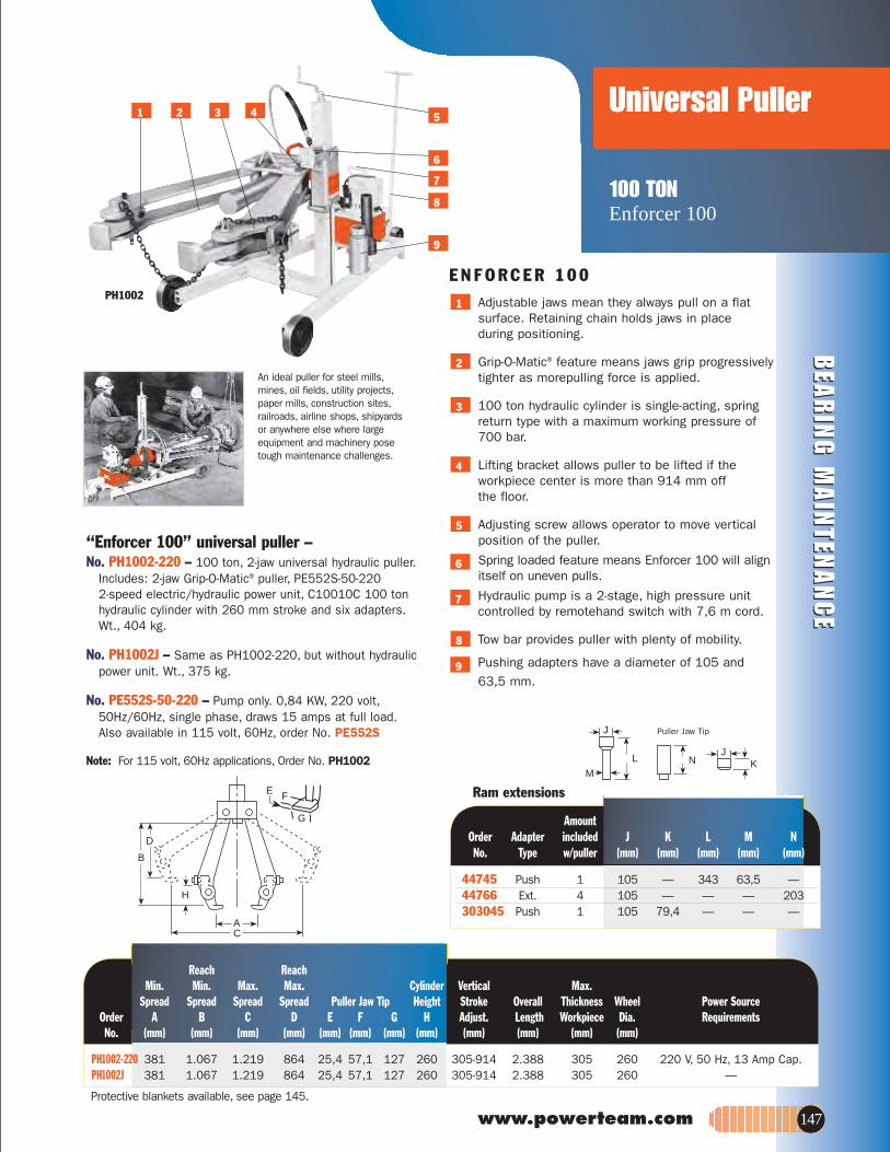
BEA
RIN
G M
AIN
TENA
NC
EB
EAR
ING
MA
INTEN
AN
CE
www.powerteam.com
MK
JL N
J
Reach Reach.xaMlacitreVrednilyC.xaM.xaM.niM.niM
Spread Spread Spread Spread Puller Jaw Tip Height Stroke Overall Thickness Wheel Power SourceOrder A B C D E F G H Adjust. Length Workpiece Dia. RequirementsNo. (mm) (mm) (mm) (mm) (mm) (mm) (mm) (mm) (mm) (mm) (mm) (mm)
PH1002-220 381 1.067 1.219 864 25,4 57,1 127 260 305-914 2.388 305 260 220 V, 50 Hz, 13 Amp Cap.PH1002J 381 1.067 1.219 864 25,4 57,1 127 260 305-914 2.388 305 260 —
Ram extensions
Amount Order Adapter included J K L M NNo. Type w/puller (mm) (mm) (mm) (mm) (mm)
Puller Jaw Tip
Universal Puller
100 TON Enforcer 100
AC
H
D
B
F
G
E
Protective blankets available, see page 145.
147
PH1002
1 3 4 5
6
7
8
9
2
“Enforcer 100” universal puller –No. PH1002-220 – 100 ton, 2-jaw universal hydraulic puller.
Includes: 2-jaw Grip-O-Matic® puller, PE552S-50-220 2-speed electric/hydraulic power unit, C10010C 100 ton hydraulic cylinder with 260 mm stroke and six adapters. Wt., 404 kg.
No. PH1002J – Same as PH1002-220, but without hydraulic power unit. Wt., 375 kg.
No. PE552S-50-220 – Pump only. 0,84 KW, 220 volt,50Hz/60Hz, single phase, draws 15 amps at full load. Also available in 115 volt, 60Hz, order No. PE552S
Note: For 115 volt, 60Hz applications, Order No. PH1002
E N F O R C E R 1 0 0 Adjustable jaws mean they always pull on a flat surface. Retaining chain holds jaws in place during positioning.
Grip-O-Matic® feature means jaws grip progressively tighter as morepulling force is applied.
100 ton hydraulic cylinder is single-acting, spring return type with a maximum working pressure of 700 bar.
Lifting bracket allows puller to be lifted if the workpiece center is more than 914 mm off the floor.
Adjusting screw allows operator to move vertical position of the puller.
Spring loaded feature means Enforcer 100 will align itself on uneven pulls.
Hydraulic pump is a 2-stage, high pressure unit controlled by remotehand switch with 7,6 m cord.
Tow bar provides puller with plenty of mobility.
Pushing adapters have a diameter of 105 and 63,5 mm.
8
5
4
3
2
1
An ideal puller for steel mills,mines, oil fields, utility projects,paper mills, construction sites,railroads, airline shops, shipyards or anywhere else where large equipment and machinery posetough maintenance challenges.
9
6
7
44745 Push 1 105 — 343 63,5 —44766 Ext. 4 105 — — — 203303045 Push 1 105 79,4 — — —

BEA
RIN
G M
AIN
TEN
AN
CE
BEA
RIN
G M
AIN
TEN
AN
CE
Roller Bearing PULLER/INSTALLER
(Railroad Edition)100 Ton Pulling Capacity
• Quickly remove or install tapered roller bearings.• Designed with cooperation of major bearing manufacturers.• It’s a fast, simple, one-man operation with 100-ton of pulling
force provided.• Completely portable for easy, convenient positioning and
out-of-the-way storage.• The standard in most wheel shops.
148
Universal railroad axle journal roller bearing puller/installer – For years,the standard in most wheel shops. Power Team now has four models to choose for greater flexibility. With both sling and jack models available and two pumps to choose from, you can tailor the unit to match your needs. With the proper equipment and know-how, removal and installation of axle journal roller bearings takes an absolute minimum of time and effort.
Each unit will service a full line of bearings with rotating end caps, from class B thru GG. No other method can match Power Team’s simplicity. Removal is very easy. Simply remove the end caps, slip the pulling shoe between the bearings and the wheel, actuate the pump, and in seconds, 100 tons of pulling force removesthe bearing. Installation is just as easy! Each unit is CSA certified (LR19814) and comes complete with a heavy-duty 100-ton hydraulic cylinder, 10,000 P.S.I. (700 bar) pump with remote control solenoid valve, hydraulic pressure gauge (No. 11543), a pulling shoe and installing tube.
* Prewired at factory for this voltage. Other voltages available upon request.
** The 1,49 KW., 115 volt requires 30 amp service.
For 220V/50Hz/Single-phase: Order PR2100J -50-220For 380V/50Hz/3-phase: Order PR3100J -50-380 (Suitable for 415V/50Hz/3 phase)
460V/60Hz/3-phase suitable for 440V/50Hz/3-phase.
Order Model Cylinder Valve Pump InformationNo. Type Type Type H.P Phase Voltage
PR2100J† Jack Double Acting Solenoid 2** 1 115 or 230*/60HzPR3100J† Jack Double Acting Solenoid 3 3 230 or 460*/60HzPR2100S† Sling Double Acting Solenoid 2 1 115 or 230*/60HzPR3100S† Sling Double Acting Solenoid 3 3 230 or 460*/60Hz
The photo above shows the UniversalPuller in position on the roller bearingassembly, which is ready for removal.
Our roller bearing pullers are ideal for replacing tough, worn-out bearingson RR freight cars.
Tooling order information - IMPORTANT...This tooling chart applies only to standard AAR configurations for freight care applications. In order to provide adapters needed to service housing-type locomotive and passenger car bearings, as well as metric bearings, Power Team must be provided with the following information: bearing manufacturer’s name and general arrangement drawing number,size of bearing to be serviced, railroad name and location and part numbers of adapters already in your possession if you currently own a Puller/Installer.
Class and size of bearing assembly”gnilooT cirteM“ PS & UBTlooT
051041031021noitpircseD
Pulling Shoe Insert Adapter No. 351830 No. 30512 No. 30521 No. 30520Guide Tube & Cap Screw Assembly No. 253341 No. 253342 No. 253343 No. 253344Cap Screw** No. 253339 No. 253394 No. 253339 No. 253395Guide Tube Adapter No. 21247 No. 21247 No. 21247 No. 21247Installing Tube Adapter Ring No. 253335 No. 253336 No. 253337 No. 253338
** Screws are supplied with the guide tube and should be ordered as replacements only.

BEA
RIN
G M
AIN
TENA
NC
EB
EAR
ING
MA
INTEN
AN
CE
www.powerteam.com
PR3100S
PR3100J
Roller Bearing PULLER/INSTALLER
(Railroad Edition)100 Ton Pulling Capacity
149
D
D
FF
AA
E E
B B
C
PR2100S/PR3100SPR2100J/PR3100J
deepSyticapaCOrder Stroke Pull Inst. Advance Pull Inst. A B C D E F WeightNo. (mm) (Tons) (Tons) (mm/min.) (mm/min.) (mm/min.) (mm) (mm) (mm) (mm) (mm) (mm) (kg)
PR2100J 394 100 68 900 81 113 813 383 1.059 912 1.981 1.493 528PR3100J 394 100 68 900 81 113 813 383 1.059 912 1.981 1.493 520PR2100S 394 100 68 900 81 113 619 279 — 1.283 1.632 985 455PR3100S 394 100 68 900 81 113 619 279 — 1.283 1.632 985 458
Note: Adapters listed above are for servicing the following roller bearingassemblies: Brenco "Crown-Taper", New Departure-Hyatt "Hy-RollTaper", SKF "Expediter" and Timken "AP".
** Screws are supplied with the guide tube and should be ordered asreplacements only.
Class and size(mm) of bearing assembly to be servicedClass B Class C Class D Class E Class EE Class EE Class F Class G Class G Class GG
Tool 108 x 203 127 x 229 140 x 254 152 x 279 140 Axle. 152 Axle. 165 x 305 178 x 305 165 Axle. 165 Axle.Description (No.) (No.) (No.) (No.) (No.) (No.) (No.) (No.) (No.) (No.)
Pulling Shoe No. 420845 is included as part of basic machine – Do Not OrderPulling Shoe — — —Insert AdapterGuide Tube & CapScrew AssemblyCap Screw**Guide TubeNo. AdapterInstalling Tube No. 420845 is included as part of basic machine – Do Not OrderInstalling Tube
420846 420846 42084630522 30512 30521 30520 30520 30519 30519
253313 253314 253317 253318 253316 253327 253320 253321 253319 253323
253156 253349 253308 253155 253307 253308 253310 253326 253309 25330923934 21248 21248 21247 21247 21247 21247 21247 21247 21247
30417 30417 3041721242 21258 21256-1 21255-1 21255-1 21257-1 21257-1 30586 30585 30585
Adapter Ring

150
PLC Synchronous Lift AN SPX BRAND
Sensor
Features• Computerized PLC System c/w Touch
Screen Panel• Control from 4 to 60 Jacking Points• 10 to 1000 Ton on each Jacking Point• Precision Accuracy at +/- 1mm full scale• Pressure / Load Display on Control Panel• Displacement Display on Control Panel• Linkage to Data Logger and Printer• Standard Hydraulic Components• System incorporates emergency alarms
with auto-stop features
Option• Basic System with Analogue Gauge• Heat Exchanger for continuous operation• Available up to 80 jacking points on request
Hydraulic Cylinder
Hydraulic HosePPS-1: Pressure Transducer / GaugePSV-1: 2/2 Way Solenoid ValvePAB-4: Advance Manifold BlockPRB-4: Retract Manifold Block
External Switch Box
PSLL-8: PLC Controller
CP-8: Control Panel
Magnetic ConnectorPDC-1: Displacement Sensor
PSC-15: 15m Sensor Cable
• For precise controlled hydraulic movement and weighing of Oil Rig Platforms, Heavy Structures, Vessels & Machineries etc.
• It uses feedback from multiple sensors to control lifting, lowering and positioning of any large, heavy or complex structure regardless of weight distribution.
• Synchronous lifting reduces the risk of bending, twisting or tilting due to uneven weight distribution or load-shifts between the lift points.
• Programmable, failsafe monitoring & safety alarms of system include operating parameters, such as displacement accuracy, lifting velocity, valve response errors.
(Optional: Data logging, load tilting, remote/online system troubleshooting)
PLC Controller
Control Panel
PLC Synchronous Lift and Lowering System
Hydraulic Pump
P150.ai 8/15/11 9:25:51 AM

‡ Some Power Team pumps are available in special configurations not listed in this catalog. Power Team can "Assemble to order" pumps with special seals, voltages,valves, relief valve settings, etc. For your special requirements please consult your local distributor or the Power Team factory.* Hand Pumps = Number of strokes required to move piston 25,4 mm.† Air, Electric and Gasoline Engine/Hydraulic pumps = Number of seconds required to move piston 25,4 mm.
The following guidelines are for generallifting and construction applications.Hydraulic tools, pullers and pressesmay fall outside these
recommendations. Always check to see that the pump’s “usable reservoir capacity” exceeds thecylinder(s) oil capacity.
Hand Pumps*
GenerallyRecommended
MarginalCheck Requirements
700 bar MaximumWorking Pressure
Not Recommended formost applications
Electric/HydraulicPumps†
Air/HydraulicPumps†
Gas/HydraulicPumps†
Page PRESSURE STAGE Cylinder Capacity (Tons)005004003002051001575503520251015.oN
34 P12‡ Single 14 32 44 65 72 9334 P55‡ Single 6 14 19 28 31 40 7135 P19/ Low 4 8 10 15 17 21
P19L High 13 30 42 59 68 8635 P59F Low 1,8 4,1 5,7 8 9 12 20 29
High 8 17 24 3 48 50 85 12235 P59(L)‡ Low 1,5 3,2 4,7 7 7,7 9,7 16,7 23,936 P157‡ High 6 14 19 28 31 40 71 10136 P159‡ Low ,5 1 1,3 1,9 2,2 2,8 5 7 9 13 1836 P300‡ High 7 15 21 30 34 43 77 110 143 200 25036 P460‡ Low ,1 ,3 ,6 ,6 ,7 ,9 1,5 2,2 2,8 4,2 5,6 8,4 11,2
High 3,3 7,7 9 14 17,5 22 37 55 71 105 143 213 284PE10 Low ,5 1,2 1,6 2,2 2,6 3,2 5,5
High 6 13,4 18,9 27 31 39 66,242 PE17‡ Low ,2 ,5 ,7 ,9 1,1 1,4 2,3 3,3 4,3 6,5 8,7
High 3,5 7,9 10,9 16 18 23 39 56,3 73 109 14643 PE18 Low ,4 ,8 1,2 1,6 1,8 2,3 3,9 5,7 7,3 10,8 14,6 21,9 29,2
High 3,3 7,5 10,3 15 17 21 37 53 69 102 136 207 27644 PE21‡ Low ,2 ,5 ,7 1,0 1,1 1,4 2,5 3,6 4,6 6,8 9,2 13,8 18,4
High 2,8 6,4 9 13 15 19 32 45,5 59 88 118 177 236PED25 Low ,2 ,4 ,6 ,9 1,0 1,3 2,2 3,2 4,1 6,1 8,3 12,0 15,7 19,9
High 2,4 5,4 7,5 10,6 12,4 15,6 26,5 38,2 49,5 73,6 99,1 144,3 188,5 238,6PE30‡ Low ,2 ,45 ,6 ,9 1 1,3 2,2 3,2 4,1 6
High 2 4,5 6 9 10 13 22 32 41 6045 PE46‡ Low ,1 ,3 ,4 ,5 ,6 ,7 1,3 1,8 2,4 3,5 4,7 7,2 9,6
High 1,3 2,9 4,1 5,9 6,8 8,6 14 22 28 42 56 84 11246-47 PE55‡ Low ,1 ,2 ,3 ,4 ,4 ,6 ,9 1,4 1,8 2,6 3,5 5,4 7,2
PE60‡ High 1,1 2,4 3,4 4,8 5,6 7,1 12 17,8 23 34 45 69 9248 PQ60 Low ,1 ,2 ,3 ,4 ,4 ,5 ,9 1,3 1,7 2,5 3,4 5,1 6,8 8,5
High 1 2,2 3,3 4,4 5,2 6,5 11 16,2 21 31 41 63 84 10549 PQ120 Low ,1 ,2 ,3 ,4 ,4 ,5 ,9 1,3 1,7 2,5 3,4 5,1 6,8 8,5
High ,5 1,1 1,6 2,2 2,6 3,2 5,5 7,7 10 15 21 30 40 5050 PE400 Low ,1 ,1 ,2 ,2 ,3 ,3 ,6 8 1 1,5 2,1 3 4 5
High ,1 ,3 ,4 ,6 ,7 ,9 1,6 2,2 2,9 4,4 5,9 8,7 11,6 14,538-39 PA6‡/ Single 10 22,4 31 44,4 51,3 65,2 - - - - -37 PA9‡ Single 10 22,4 31 44,4 51,3 65,2 - - - - -40 PA17‡ Low ,2 ,5 ,7 ,9 1,1 1,4 2,3 3,3 4,3 6,5 8,7 - -
High 3,5 7,9 10,9 16 18 23 39 56 73 109 14641 PA46‡ Low ,1 ,3 ,4 ,5 ,6 ,7 1,3 2 2,4 3,5 4,7 7,2 9,6
High 1,3 2,9 4,1 5,9 6,8 8,6 14 22 28 56 42 84 11241 PA55‡ Low ,1 ,3 ,4 ,6 ,7 ,9 1,5 2,2 2,8 4,1 5,5 8,4 11,2
High 1,1 2,4 3,4 4,8 5,6 7,1 12 18 23 34 45 69 9251 PG30 Low ,3 ,7 1 1,3 1,6 2 3,3 4,8 6,2 9,3 12,4 18,1 -
High 2 4,5 6,3 8,9 10,3 13 22 31,8 41,3 61,4 83 121 -51 PG55‡ Low ,1 ,3 ,4 ,6 ,7 ,8 1,4 2 2,6 3,9 5,2 7,6 9,9 12,5
High 1,1 2,5 3,5 4,9 5,6 7,1 12,1 17,3 22,5 33,5 45 66 86 10952-53 PG120‡ Low ,1 ,3 ,4 ,6 ,7 ,8 1,4 2 2,6 3,9 5,2 7,6 9,9 12,5
High ,5 1,0 1,5 2,0 2,4 3,0 5,1 7,3 9,5 14,2 19,1 27,8 36,3 46,052-53 PG400 Low ,1 ,1 ,2 ,2 ,3 ,3 ,6 ,8 1,0 1,5 2,0 3,0 3,8 4,9
High ,2 ,3 ,5 ,7 ,8 1,0 1,7 2,4 3,1 4,6 6,2 9,0 11,8 15,0
www.powerteam.com 151
Pump CapacitySELECTION CHART
Choosing the Right Pump
P151ai.ai 7/20/11 12:08:53 PM

CY
LIN
DE
RS
152
Seal Kits
Accessories
* These seals come standard on all above products. Refer Parts List for correct model no. & more details.
300942
P12 A 300260 300507 P23 B 300943 300472 P55 B 300943 300472 P19 A 300894P19L 3000179P59 C 300506 300510 P59F B 300814 300815 P59L 3000178P157 C 300942 300690 300691P159 C 300942 300690 300691P300 B 300695 300696 300697P460 D 300811 300812 300813P157D C 300692 300693 300694P159D C 300692 300693 300694 P300D B 300698 300699P460D D 300811 300812 300813
Couplers Repair Viton EPR Order No. Model Kit* Seal Kit Seal Kit
9795 209100 9796-V 9796-E 9796 300826 & 209100 9796-V 9796-E
PE102-220 B 300651 300653PE102A-220 B 300651 300653PE104-220 B 300651 300653PE172-50-220 A 300430 300648PE172A-50-220 A 300430 300648PE172M-50-220 A 300430 300648PE174-50-220 A 300430 300648PE174M-50-220 A 300430 300648PE182-50-220 C 300914PE183-2-50-220 C 300914PE183-50-220 C 300914 PE183A-50-220 C 300914 PE184-2-50-220 C 300914 PE184-50-220 C 300914
Electric Powered Pump Model Repair Viton EPR Order No. Kit* Seal Kit Seal Kit
PA172 B 300430 300648PA174 B 300430 300648PA6 F 300805PA6-2 F 300848PA64 F 300883PA6A F 300840PA6AM F 300840PA6D F 300844PA6D2 F 300850PA6DM F 300844PA6DM-1 F 300844PA6DM-2 F 300850PA6M F 300805PA6M-1 F 300831PA6M-2 F 300848PA6R F 301030PA6RM F 301030PA9 B 300949PA9H B 300949
Air Powered Pump Model Repair Viton EPR Order No. Kit* Seal Kit Seal Kit
FC2200 300373FC4400 300376HFS3A A 300404HFS6A B 300116HNS225 B 300147HP20 A 300879HP35 A 300608HS2000 A 300514HS3000 A 300620
Hydraulic Tools Model Repair Order No. Kit*
9500 3004519504 3004519506 3004519508 3004519509 3004519511 3004519512 C 3008359519 C 3008359520 3004519552 B 3003329555 C 3008359556 3004899569 3006059570 3006059575 A 3006839581 B 273459582 B 3001299628 D 3005719632 3005949642 3005929644 300593
Valves Model Repair Order No. Kit*
Handpump Repair Viton EPR Order No. Model Kit* Seal Kit Seal Kit
P152.ai 7/20/11 12:11:25 PM

www.powerteam.com 153
Seal Kits
Accessories
Cylinder Seal VitonOrder Kit* Seal No. Kit
RH121 300576 —RH121T 300576 —RH123 300576 —RH202 300615 —RH203 300069 300222RH206 300615 —RH302 300037 300223RH306 300037 300223RH503 300059 300225RH603 300477 300476RH606 300477 300476RH1003 300485 300585RH303 300077 300224RH306D 300822 300224RH3010 300625 —RH605 300269 300226RH6010 300626 —RH1001 300927 —RH1006 300295 300227RH10010 300629 —RH1505 300154 300228RH1508 300583 —RH2008 300582 —RHA306 300867 300868RHA604D 300269 300226RLS50 300454 —RLS100 300455 —RLS200 300456 —RLS300 300457 —RLS500S 300458 —RLS750S 300459 —RLS1000S300460 —RLS1500S300461 —RP25 300628 —RP55 300627 —RSS101 300010 —RSS202 300011 —RSS302 300297 —RSS502 300292 —RSS1002 300293 —RSS2503 — —RSS1002D300578 —RT172 300358 —RT302 300359 —RT503 300360 —RT1004 300024 —
R35510L 300679 —R4302L 300680 —R4306L 300680 —R43010L 300680 —R5652L 300681 —R5656L 300681 —R56510L 300681 —RA202 300631 —RA204 300631 —RA206 300631 —RA302 300632 —RA304 300632 —RA306 300632 —RA552 300391 —RA554 300391 —RA556 300391 —RA5510 300391 —RA1002 300444 —RA1006 300444 —RA556L 300395 —RA1006L 300396 —RD106 300017 —RD1010 300017 —RD256 300118 —RD2514 300118 —RD556 300005 —RD5513 300005 —RD5518 300005 —RD8013 300410 —RD1006 300006 —RD10013 300006 —RD10020 300006 —RD1506 300007 —RD15013 300007 —RD15018 300007 —RD2006 300008 —RD20013 300008 —RD3006 300466 —RD30013 300466 —RD4006 300467 —RD40013 300467 —RD5006 300468 —RD50013 300468 —RH102 300071 300221RH108 300071 300221
RH120 300657 —
Cylinder Seal VitonOrder Kit* Seal No. Kit
R20010C 300677 —R2802C 300678 —R2806C 300678 —R28010C 300678 —
Cylinder Seal VitonOrder Kit* Seal No. Kit
R3552C 300679 —R3556C 300679 —R35510C 300679 —R4302C 300680 —R4306C 300680 —R43010C 300680 —R5652C 300681 —R5656C 300681 —R56510C 300681 —R1002D 301042 —R1006D 301042 —R10010D 301042 —R1502D 301043 —R1506D 301043 —R15010D 301043 —R2002D 301044 —R2006D 301044 —R20010D 301044 —R2802D 301045 —R2806D 301045 —R28010D 301045 —R3552D 301046 —R3556D 301046 —R35510D 301046 —R4302D 301047 —R4306D 301047 —R43010D 301047 —R5652D 301048 —R5656D 301048 —R56510D 301048 —R552L 300674 —R556L 300674 —R5510L 300674 —R1002L 300675 —R1006L 300675 —R10010L 300675 —R1502L 300676 —R1506L 300676 —R15010L 300676 —R2002L 300677 —R2006L 300677 —
R20010L 300677 —R2802L 300678 —R2806L 300678 —R28010L 300678 —R3552L 300679 —R3556L 300679 —
Cylinder Seal VitonOrder Kit* Seal No. Kit
C51C 300404 300210C53C 300404 300210C55C 300404 300210C57C 300404 300210C59C 300404 300210C101C 300116 300211C102C 300116 300211C104C 300116 300211C106C 300116 300211C108C 300116 300211C1010C 300116 300211C1012C 300116 300211C1014C 300116 300211C1016C 300116 300211C151C 300453 300471C152C 300453 300471C154C 300453 300471C156C 300453 300471C158C 300453 300471C1510C 300453 300471C1512C 300453 300471C1514C 300453 300471C1516C 300453 300471C251C 300147 300213C252C 300147 300213C254C 300147 300213C256C 300147 300213C258C 300147 300213C2510C 300147 300213C2512C 300147 300213C2514C 300147 300213C552C 300114 300215C554C 300114 300215C556C 300114 300215C5510C 300114 300215C5513C 300114 300215C756C 300647 300846C7513C 300647 300846C1002C 300112 300216C1006C 300112 300216C10010C 300112 300216C55CBT 300404 300210C106CBT 300116 300211C1010CBT300116 300211C256CBT 300147 300213C2514CBT 300147 300213 R552C 300674 —R556C 300674 —R5510C 300674 —R1002C 300675 —R1006C 300675 —
* These seals come standard on all above cylinders. Refer Parts List for correct model no. & more details.
300114
R10010C 300675 —R1502C 300676 —R1506C 300676 —R15010C 300676 —R2002C 300677 —R2006C 300677 —
P153.ai 7/20/11 12:11:55 PM

154
ASME B30.1 Power Team hydraulic cylinders fully comply with the criteria set forth in the American Society of MechanicalEngineers standard ASME B30.1:
1. Our cylinders are designed to have a minimum of a 2-to-1 safety factor on typical material yield strength; Each cylinder is tested at 125 percent of rated pressure at full travel and is inspected to assure functionality and freedom from leaks.
ASME B40.1 Power Team heavy-duty pressure gauges are designedin accordance with the recommendations set forth inthe American Society of Mechanical Engineers standardASME B40.1, Grade B.
CE MARK Power Team is committed to designing, manufacturing,and marketing products that meet or exceed the needsof the customers we serve. Power Team supplies aLetter of Incorporation or a Declaration of Conformity and CE Marking for products that conform withEuropean community directives.
IJ100 Power Team hoses meet the criteria set forth in theMaterial Handling Institute’s specification #IJ100 forhydraulic hose. Under the procedures outlined in thisstandard, hydraulic hose shall:
1. Have an average minimum life of 30,000 cycles at full rated capacity.
2. Have a minimum burst pressure of at least twice the rated operating pressure.
CSA Where specified, Power Team electric power pumpassemblies meet the design, assembly, and testrequirements of the Canadian Standards Association.
Note: If CSA certification is required, it must be requested at the time thepump is ordered.
NEMA Where specified, Power Team electric power pumpassemblies meet the design, assembly, and test require-ments of NEMA 12, a National Electrical Manufacturers’Association standard relating to electrical componentsused to resist moisture and dust.
POWER TEAM PRODUCT DESIGN CRITERIA All Power Team brand hydraulic components aredesigned and/or tested to be safe for use at maximumoperating pressures of 700 bar unless otherwisespecifically noted.
QUALITY ASSURANCE All of our hydraulic cylinders are subjected to qualitychecks during production. All steel bar is certified andhas material traceability to the mill. Before leaving thefactory, all cylinders are pressure tested to 875 bar,except the RT series which are tested to 700 bar toinsure on-the-job reliability. We have made every effortto include the latest specifications for our products inthis catalog. Please call the Power Team factory for themost current product specifications. The Power TeamLifetime Marathon Warranty is described in more detailon page 155 of this catalog.
Power Team’s commitment to quality is evident in everything we do, from raw material receipt to how we supportour customers years after they purchase our products. Power Team is registered to ISO 9001: 2000 internationalquality standard. ISO 9001: 2000 requires compliance with standards for management, administration, productdevelopment, manufacturing and continual improvement. Our Registration verifies that Power Team has adoptedand maintains documentation for processes ranging from suppliers to customers, inspection, handling, and training. ISO 9001 also requires periodic internal and external audits to ensure all aspects of work affecting qualitycontrol are monitored. This always has been, and will continue to be, our philosophy. That’s our guarantee to you.
Standards

LIFETIMEMARATHON™
WARRANTY
All Power Team products and parts, with the exception noted below, are warranted against defects in materials and workmanship for the life of the product or part. (The life of the product or part is defined as that point in time when it no longer functions due to normal wear.) This warranty does not cover any product or part that has been worn out, abused, heated, ground or otherwise altered, used for a purpose other than that for which it was intended or used in a manner inconsistent with any instructions regarding its use. Chains, batteries, electric motors, gas engines, knives and cutter blades which are sold with Power Team products are not covered by this warranty. All electric motors and gas engines are separately warranted by their manufacturer under the conditions stated in their separate warranty.
Power Team's electronic products are warranted against defects in material and workmanship for one year.
To qualify for warranty consideration, return the Power Team product, freight prepaid, to a Power Team authorized repair center or to the Power Team factory. If any product or part manufactured by Power Team is found to be defective by Power Team, in its sole judgement, Power Team will, at its option, either repair or replace such defective product or part and return it via best ground transportation, freight prepaid. THIS REMEDY SHALL BE THE EXCLUSIVE REMEDY AVAILABLE FOR ANY DEFECTS IN THE PRODUCTS OR PARTS MANUFACTURED AND SOLD BY POWER TEAM OR FOR DAMAGES RESULTING FROM ANY OTHER CAUSE WHATSOEVER, INCLUDING WITHOUT LIMITATION, POWER TEAM'S NEGLIGENCE. POWER TEAM SHALL NOT, IN ANY EVENT, BE LIABLE TO ANY BUYER FOR CONSEQUENTIAL OR INCIDENTAL DAMAGES OF ANY KIND, WHETHER FOR DEFECTIVE OR NON-CONFORMING GOODS, NEGLIGENCE, ON THE BASIS OF STRICT LIABILITY OR FOR ANY OTHER REASON.
Power Team's warranty is expressly limited to persons who purchase Power Team's products or parts for the resale or use in the ordinary course of the buyer's business.
THIS WARRANTY IS EXCLUSIVE, AND POWER TEAM MAKES NO OTHER WARRANTY OF ANY KIND WHATSOEVER, EXPRESSED OR IMPLIED, WITH RESPECT TO THE PRODUCTS MANUFACTURED AND SOLD BY IT, WHETHER AS TO MERCHANTABILITY, FITNESS FOR A PARTICULAR PURPOSE, OR ANY OTHER MATTER. No agent, employee or representative of Power Team has any authority to bind Power Team to any affirmation, representation or warranty concerning Power Team products or parts, except as stated herein.
The purpose of this exclusive remedy shall be to provide the buyer with repair or replacement of products or parts manufactured by Power Team found to be defective in materials or workmanship or negligently manufactured. This exclusive remedy shall not be deemed to have failed of its essential purpose so long as Power Team is willing and able to replace said defective products or parts in the prescribed manner.
www.powerteam.com 155

P O W E R T E A M . C O M
102-121
CY
LIN
DE
RS
PU
MP
SA
CC
ES
SO
RIE
SS
HO
PE
QU
IPJA
CK
ST
OO
LS
PU
LL
ER
S
81-89
71-80
36-69
World HeadquartersThe AmericasCustomer Service Center
5885 11th StreetRockford, Illinois 61109Tel: 815-874-5556
Customer Service/Order EntryTel : 800.541.1418Fax: 800.288.7031
Technical ServicesTel : 800.477.8326Fax: [email protected]
EuropeanCustomer Service Center
Albert Thijsstraat 126471 WX EygelshovenThe NetherlandsTel : 31 (45) 5678877Fax: 31 (45) [email protected]
Asia PacificCustomer Service Center
7 Gul CircleSingapore 629563SingaporeTel : (65) 6265 3343Fax: (65) 6265 [email protected]
ChinaCustomer Service Center
No. 1568 Hua Shan RoadTreasury Building11th FloorShanghai 200052, ChinaTel : 86 (21) 2208.5888Fax: 86 (21) [email protected]
9-26
90-101
122-149
© 2009 SPX Hydraulic Technologies
www.powerteam.com
AN SPX BRAND
Distributed by:
PT Hydraulics Australia Pty Ltd19 Ricketts RoadMt Waverley, VIC, 3149
P: 03 9562 8800F: 03 9562 8080
E: [email protected]: www.pthydraulics.com.au