
HYDRAULIC PUMP - Hytorc PumpsCONNECTING THE HYDRAULIC WRENCH When using hydraulic hoses for a tool...
40
HYDRAULIC PUMP OPERATIONS MANUAL 3rd. Edition: Mar. 2015
Transcript of HYDRAULIC PUMP - Hytorc PumpsCONNECTING THE HYDRAULIC WRENCH When using hydraulic hoses for a tool...
HYDRAULIC PUMPOPERATIONS MANUAL
3rd. Edition: Mar. 2015

This manual applies to all pumps in the Hydraulic Pump Product Families. It is recommended the manual is kept up-to-date by checking the edition and date code at the bottom of this page by utilizing the HYTORC website and downloading a copy of the most recent edition as needed.
HYTORC Corporate Headquarters333 Route 17 NorthMahwah, NJ 07430, USA
Notice: The information contained in this document is subject to change without notice. HYTORC makes no warranty of any kind with regard to this material, including but not limited to, the implied warranties of merchantability and fitness for a particular purpose. HYTORC shall not be liable for errors contained herein or for incidental or consequential damages in connection with the furnishing, performance, or use of this material. It is further recomended that the end-user or repair technician insure they have obtained and are familiar with the latest revision of the manual for the equipment outlined in this document.
Restricted Rights Legend: Use and duplication of the information contained within this manual is limited to the purchaser, end user, or licensed Hytorc representative. It is recommended that proper training for the equipment outlined in this manual be conducted by a HYTORC authorized training representative for any person who is operating or repairing the equipment outlined in this document. Modification, or disclosure by any other agency or representative is strictly forbidden.
Product Modifications: Hytorc Corporation DOES NOT ALLOW any of the products listed in this manual to be modified by any end user without exception. Should an application require a modification to the tool, or any of the standard accessories please consult with your local HYTORC representative and they will be able to obtain the assistance for any modification that may be required.
Copyright © 2015 by HYTORC Division UNEX Corporation. All rights reserved. Reproduction, adaptation, or translation without prior written permission is prohibited, except as allowed under the copyright laws.
3rd. Edition. Printed in USA. March 2015Complies with standards publication BS EN 82079-1:2012
HYDRAULIC PUMPS PRODUCT FAMILY:JETPRO-S 115/230, HYSTREAM 115/230, HY-115/230, HY-115-FA1, HY-115-FA4, BigJet 18-400, HY-AIR
EN, EN-ISO, ISO Standards:
For a complete EC declaration of conformity or if you require any further assistance please contact your local HYTORC representative or 1-800-FOR-HYTORC (1-800-367-4986) or on the web at www.hytorc.com.
EN 982:2009EN 61310-2:2008EN 61310-3:2008ISO 3744:2011
EN ISO 12100-1:2011EN ISO 12100-2:2011EN ISO 14121-1:2007EN ISO 11148-6:2012
STAY
SAFE
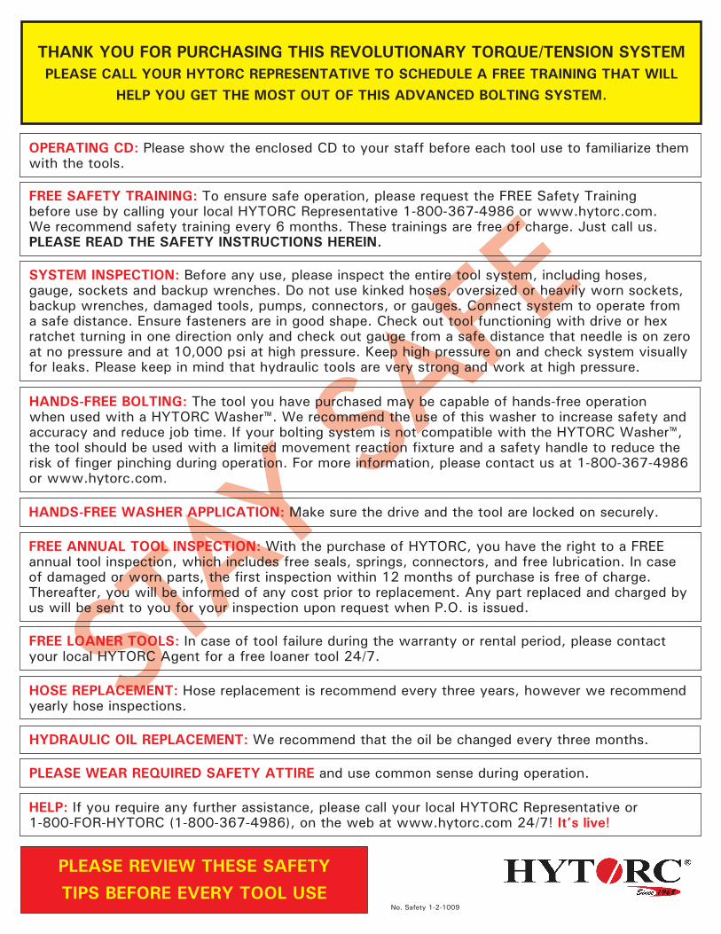
THANK YOU FOR PURCHASING THIS REVOLUTIONARY TORQUE/TENSION SYSTEM PLEASE CALL YOUR HYTORC REPRESENTATIVE TO SCHEDULE A FREE TRAINING THAT WILL
HELP YOU GET THE MOST OUT OF THIS ADVANCED BOLTING SYSTEM.
OPERATING CD: Please show the enclosed CD to your staff before each tool use to familiarize them with the tools.
FREE SAFETY TRAINING: To ensure safe operation, please request the FREE Safety Training before use by calling your local HYTORC Representative 1-800-367-4986 or www.hytorc.com. We recommend safety training every 6 months. These trainings are free of charge. Just call us. PLEASE READ THE SAFETY INSTRUCTIONS HEREIN.
SYSTEM INSPECTION: Before any use, please inspect the entire tool system, including hoses, gauge, sockets and backup wrenches. Do not use kinked hoses, oversized or heavily worn sockets, backup wrenches, damaged tools, pumps, connectors, or gauges. Connect system to operate from a safe distance. Ensure fasteners are in good shape. Check out tool functioning with drive or hex ratchet turning in one direction only and check out gauge from a safe distance that needle is on zero at no pressure and at 10,000 psi at high pressure. Keep high pressure on and check system visually for leaks. Please keep in mind that hydraulic tools are very strong and work at high pressure.
HANDS-FREE WASHER APPLICATION: Make sure the drive and the tool are locked on securely.
FREE ANNUAL TOOL INSPECTION: With the purchase of HYTORC, you have the right to a FREE annual tool inspection, which includes free seals, springs, connectors, and free lubrication. In case of damaged or worn parts, the first inspection within 12 months of purchase is free of charge. Thereafter, you will be informed of any cost prior to replacement. Any part replaced and charged by us will be sent to you for your inspection upon request when P.O. is issued.
FREE LOANER TOOLS: In case of tool failure during the warranty or rental period, please contact your local HYTORC Agent for a free loaner tool 24/7.
HOSE REPLACEMENT: Hose replacement is recommend every three years, however we recommend yearly hose inspections.
PLEASE WEAR REQUIRED SAFETY ATTIRE and use common sense during operation.
HELP: If you require any further assistance, please call your local HYTORC Representative or1-800-FOR-HYTORC (1-800-367-4986), on the web at www.hytorc.com 24/7! It’s live!
PLEASE REVIEW THESE SAFETY TIPS BEFORE EVERY TOOL USE
No. Safety 1-2-1009
HANDS-FREE BOLTING: The tool you have purchased may be capable of hands-free operation when used with a HYTORC Washer™. We recommend the use of this washer to increase safety and accuracy and reduce job time. If your bolting system is not compatible with the HYTORC Washer™, the tool should be used with a limited movement reaction fixture and a safety handle to reduce the risk of finger pinching during operation. For more information, please contact us at 1-800-367-4986 or www.hytorc.com.
HYDRAULIC OIL REPLACEMENT: We recommend that the oil be changed every three months.
CONTENTS
HYDRAULIC PUMPOPERATIONAL MANUAL
INTRODUCING HYTORC 5SECTION IGENERAL OPERATING INSTRUCTIONS 6SECTION IIPUMP AND OPERATIONAL CONTROL 7
SECTION IIICONNECTING THE HYDRAULIC WRENCH 8
SECTION IVFUNCTIONAL CHECK 9
SECTION VREMOTE CONTROL 10
SECTION VISETTING PRESSURE AND TORQUE 11
SECTION VIILED LIGHTS FOR SYSTEM MONITORING 13
SECTION VIIIATEX EXPLOSION PROTECTION 14
SECTION IXPREVENTATIVE MAINTENANCE 18
SECTION XTROUBLESHOOTING 19
APPENDICES 23A User Manual FA1B User Manual FA4C Declaration of ConformityD ATEX Explosion Proof Certificate E Material Safety Data SheetF Material Safety Data Sheet Canada
5 Leading Innovation in Industrial Bolting Since 1968
The World’s Most Trusted Industrial Bolting Systems

THANK YOU FOR BUYING HYTORC!YOU ARE NOW HOLDING ONE OF THE WORLD'S LARGEST SELLING ANDMOST ADVANCED INDUSTRIAL BOLTING SYSTEMS.
HYTORC is used more often, by more industries on more applications than all others combined. If you maintain your new pump properly, it will last for years to come.
This manual is designed to provide you with the basic knowledge required to operate and maintain your HYTORC pump. Please read this manual carefully and follow the instructions provided. If you have any questions regarding your HYTORC tool, please call us directly at 201-512-9500 or fax 201-512-0530.
Finally, your purchase of this HYTORC tool entitles you to the following FREE services:
• Free on-site training in the application and operation of your HYTORC equipment
• Free semi-annual training
• Free annual inspection
• Free loaner in case of pump failure
• Free engineering assistance by calling 1 800 FOR-HYTORC, or our continental office
Your local HYTORC office was informed of the delivery of this equipment. Should you require immediate training, please feel free to call us directly to arrange an appointment with you at your convenience.
An instructional CD is also available for basic training and occasional brush up on operating procedures.
For additional information please visit our website at www.hytorc.com
Again, thank you and welcome to HYTORC!
Worldwide WarrantyHYTORC equipment is engineered to the latest technological standards and is backed by our exclusive 12-word, 12-month warranty.
"YOU BREAK IT UNDER NORMAL USE, WE FIX IT FREE OF CHARGE!"
If a HYTORC Pump cannot be repaired on-site, FREE loaner HYTORC equipment will be made available to you upon request.UNEX CORPORATION OR ITS DEALERS SHALL NOT BE LIABLE FOR LOSS OF PRODUCT OR OTHER INCIDENTAL OR CONSEQUENTIAL COSTS INCURRED BY THE BUYER OR THE USER.
HYTORC Offices WorldwideEurope HYTORC Europe Tel. 33-1-4288-6745
Japan HYTORC Japan Tel. 81-3-3314-3315
Australia HYTORC Australia Tel. 61-8-8293-8411
United Kingdom HYTORC UK Tel. 44-16-7036-3800
Brazil HYTORC South America Tel. 55-21-2223-2944
All Others HYTORC USA Tel. 201-512-9500 /800-FOR-HYTORC
6 Leading Innovation in Industrial Bolting Since 1968
The World’s Most Trusted Industrial Bolting Systems
SECTION I
GENERAL OPERATING INSTRUCTIONS
All HYTORC Power Packs operate in a pressure range from 500 to 10,000 PSI, and are fully adjustable. They have been engineered and designed for portability and high flow for increased speed. Before using your HYTORC powerpack, check the following points:
• Is the reservoir filled with oil?
• Where is the closest electrical outlet at the job site?
• Is there enough air pressure (100 PSI) and flow at the job site? (Pnuematic only)
• Is the gauge mounted and rated for 10,000 PSI?
• Is the oil filler plug securely in place?
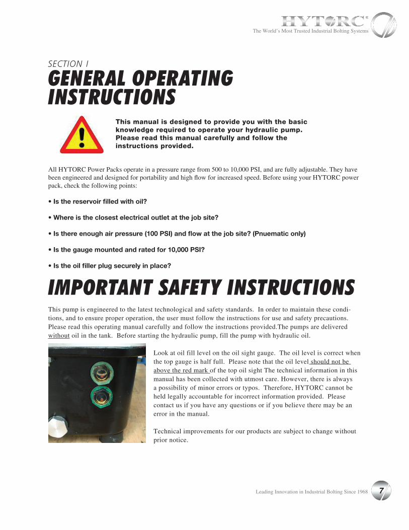
IMPORTANT SAFETY INSTRUCTIONSThis pump is engineered to the latest technological and safety standards. In order to maintain these condi-tions, and to ensure proper operation, the user must follow the instructions for use and safety precautions.Please read this operating manual carefully and follow the instructions provided.The pumps are delivered without oil in the tank. Before starting the hydraulic pump, fill the pump with hydraulic oil.
Look at oil fill level on the oil sight gauge. The oil level is correct when the top gauge is half full. Please note that the oil level should not be above the red mark of the top oil sight The technical information in this manual has been collected with utmost care. However, there is always a possibility of minor errors or typos. Therefore, HYTORC cannot be held legally accountable for incorrect information provided. Please contact us if you have any questions or if you believe there may be an error in the manual.
Technical improvements for our products are subject to change without prior notice.
This manual is designed to provide you with the basic knowledge required to operate your hydraulic pump. Please read this manual carefully and follow the instructions provided.
7 Leading Innovation in Industrial Bolting Since 1968
The World’s Most Trusted Industrial Bolting Systems
SECTION II
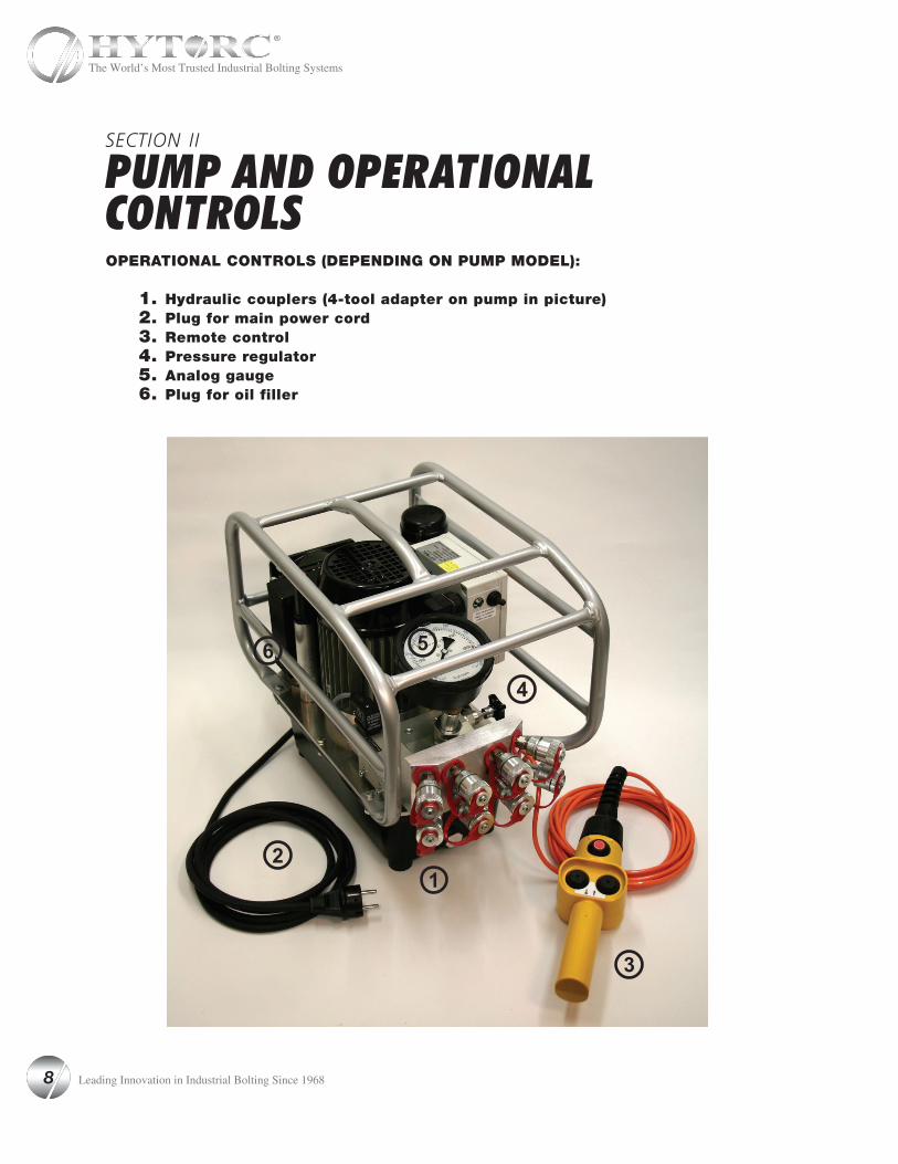
PUMP AND OPERATIONAL CONTROLS OPERATIONAL CONTROLS (DEPENDING ON PUMP MODEL):
1. Hydraulic couplers (4-tool adapter on pump in picture)2. Plug for main power cord3. Remote control4. Pressure regulator5. Analog gauge6. Plug for oil filler
12
3
4
56
8 Leading Innovation in Industrial Bolting Since 1968
The World’s Most Trusted Industrial Bolting Systems
SECTION III
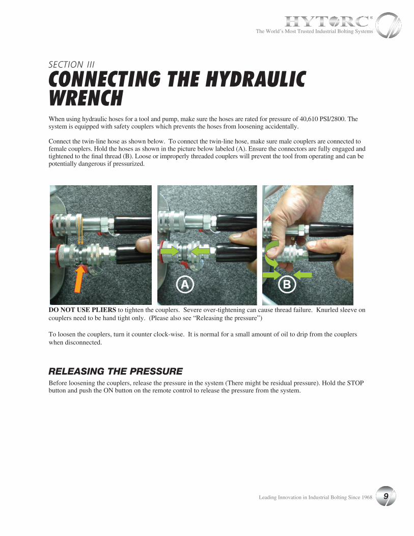
CONNECTING THE HYDRAULIC WRENCHWhen using hydraulic hoses for a tool and pump, make sure the hoses are rated for pressure of 40,610 PSI/2800. The system is equipped with safety couplers which prevents the hoses from loosening accidentally.
Connect the twin-line hose as shown below. To connect the twin-line hose, make sure male couplers are connected to female couplers. Hold the hoses as shown in the picture below labeled (A). Ensure the connectors are fully engaged and tightened to the final thread (B). Loose or improperly threaded couplers will prevent the tool from operating and can be potentially dangerous if pressurized.
DO NOT USE PLIERS to tighten the couplers. Severe over-tightening can cause thread failure. Knurled sleeve on couplers need to be hand tight only. (Please also see “Releasing the pressure”)
To loosen the couplers, turn it counter clock-wise. It is normal for a small amount of oil to drip from the couplers when disconnected.
RELEASING THE PRESSUREBefore loosening the couplers, release the pressure in the system (There might be residual pressure). Hold the STOP button and push the ON button on the remote control to release the pressure from the system.
9 Leading Innovation in Industrial Bolting Since 1968
The World’s Most Trusted Industrial Bolting Systems
SECTION IV
FUNCTIONAL CHECKAll HYTORC pumps are supplied completely assembled and are ready to use. A HYTORC Hydraulic Power Pack, for use with your HYTORC tools, is recommended to provide the safety, speed, pressure and portability that make the tools more efficient and accurate.
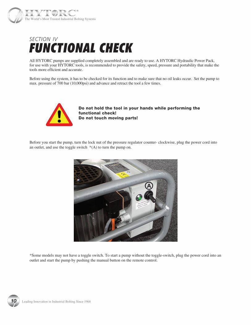
Before using the system, it has to be checked for its function and to make sure that no oil leaks occur. Set the pump to max. pressure of 700 bar (10,000psi) and advance and retract the tool a few times.
Before you start the pump, turn the lock nut of the pressure regulator counter- clockwise, plug the power cord into an outlet, and use the toggle switch *(A) to turn the pump on.
Do not hold the tool in your hands while performing the functional check!Do not touch moving parts!
*Some models may not have a toggle switch. To start a pump without the toggle-switch, plug the power cord into an outlet and start the pump by pushing the manual button on the remote control.
A
10 Leading Innovation in Industrial Bolting Since 1968
The World’s Most Trusted Industrial Bolting Systems

SECTION V
REMOTE CONTROLThe pumps can be equipped with different remote control models. However, the mode of operation for any remote control is:
• PUSH (A)-PUMP IS ON / TOOL ADVANCES • RELEASE (A)-PUMP IS ON / TOOL RETRACTS• PUSH (B)-PUMP IS OFF• PUSH AND HOLD (C)-TOOL ADVANCES AND RETRACTS AUTOMATICALLY UNTIL (C) IS RELEASED• TOGGLE SWITCH (D)-FORWARD (ON) DOWNWARD (OFF) (PNUEMATIC PUMPS)
MANUAL PUMP AUTOMATIC PUMP
A
A A
A
A
A
B
C
C
C
C
A
A
B
B B
D D
B
B
11 Leading Innovation in Industrial Bolting Since 1968
The World’s Most Trusted Industrial Bolting Systems
SECTION VI
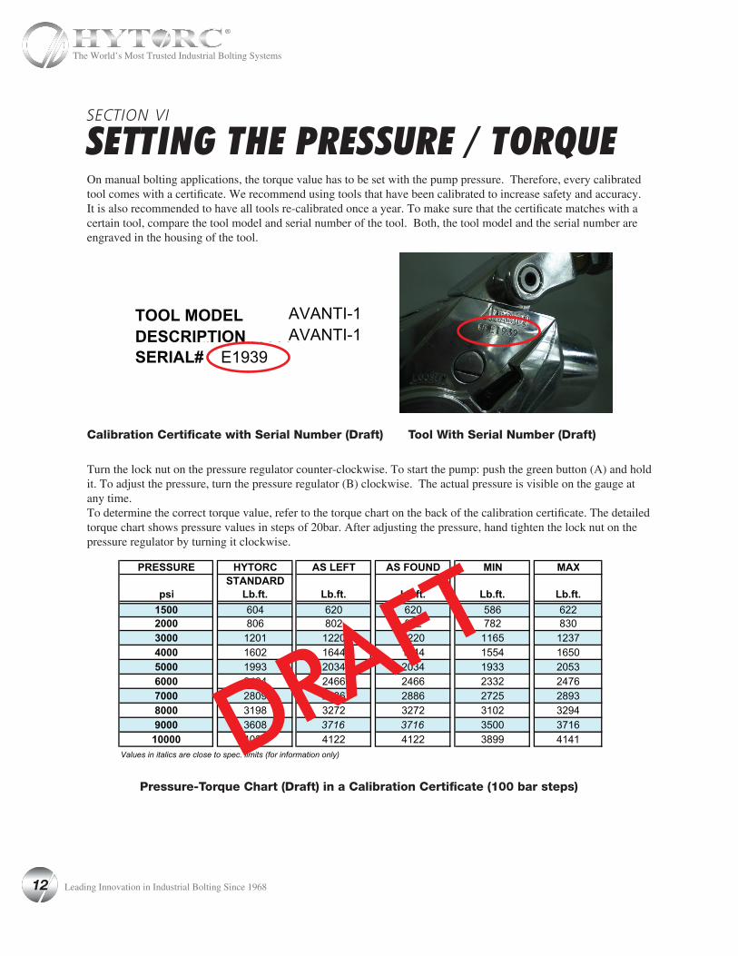
SETTING THE PRESSURE / TORQUEOn manual bolting applications, the torque value has to be set with the pump pressure. Therefore, every calibrated tool comes with a certificate. We recommend using tools that have been calibrated to increase safety and accuracy. It is also recommended to have all tools re-calibrated once a year. To make sure that the certificate matches with a certain tool, compare the tool model and serial number of the tool. Both, the tool model and the serial number are engraved in the housing of the tool.
Turn the lock nut on the pressure regulator counter-clockwise. To start the pump: push the green button (A) and hold it. To adjust the pressure, turn the pressure regulator (B) clockwise. The actual pressure is visible on the gauge at any time.To determine the correct torque value, refer to the torque chart on the back of the calibration certificate. The detailed torque chart shows pressure values in steps of 20bar. After adjusting the pressure, hand tighten the lock nut on the pressure regulator by turning it clockwise.
AVANTI-1 E1939 AVANTI-1
AVANTI-1 E1939 AVANTI-1
AVANTI-1 E1939 AVANTI-1
Calibration Certificate with Serial Number (Draft)
Pressure-Torque Chart (Draft) in a Calibration Certificate (100 bar steps)
Tool With Serial Number (Draft)
DRAFT
12 Leading Innovation in Industrial Bolting Since 1968
The World’s Most Trusted Industrial Bolting Systems
Applying the Torque Wrench - the Tightening Process1. Having set your target pressure, cycle the tool three or four times to full pressure before putting it on the
application. Cycling the tool ensures that the system is operating properly and removes trapped air, if any.2. Place the proper size impact socket on the square drive and secure properly with a locking ring and pin.3. Place the tool and the socket on the nut, making sure that the socket has fully engaged the nut. Further ensure
that the drive retainer is engaged.4. Make sure the reaction arm is firmly abutted against a stationary object (e.g. An adjacent nut, flange, equipment
housing etc.)5. When positioning the wrench, make sure that the hose connections are well clear of any obstructions, and that
all body parts are safely out of harm’s way.6. THEN, AND ONLY THEN, apply momentary pressure to the system to ensure proper tool placement. If it
doesn’t look or act right, stop and re-adjust the reaction arm.
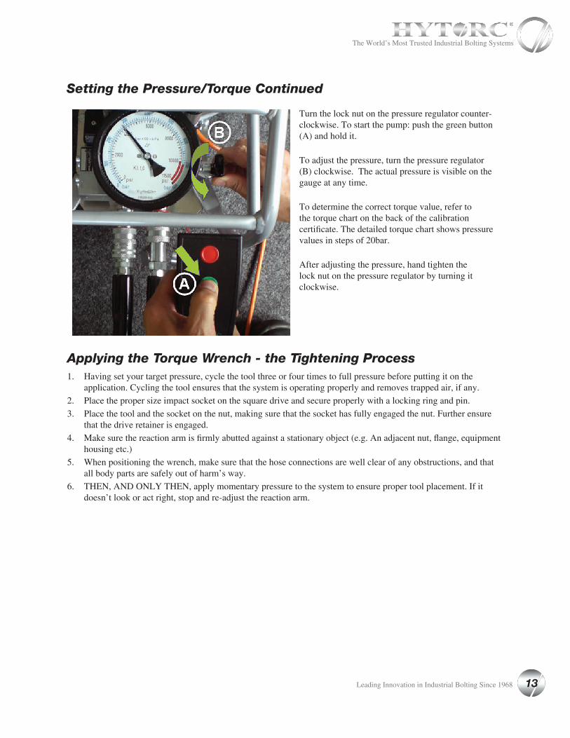
Setting the Pressure/Torque Continued
Turn the lock nut on the pressure regulator counter-clockwise. To start the pump: push the green button (A) and hold it.
To adjust the pressure, turn the pressure regulator (B) clockwise. The actual pressure is visible on the gauge at any time.
To determine the correct torque value, refer to the torque chart on the back of the calibration certificate. The detailed torque chart shows pressure values in steps of 20bar.
After adjusting the pressure, hand tighten the lock nut on the pressure regulator by turning it clockwise.
13 Leading Innovation in Industrial Bolting Since 1968
The World’s Most Trusted Industrial Bolting Systems

SECTION VII
LED LIGHTS FOR SYSTEM MONITORINGThe HY-115 Pump is now equipped with (3) three-colored LEDs integrated into the electric control box for system monitoring.
Upper LED: Low voltage• green when voltage above 95V = o.k.• yellow when voltage between 95V and 80V• red when voltage below 80V• motor switches off when below 77V for more
than 5 seconds
Middle LED: High voltage
While not running• generally green when voltage below 138V• when above 138V all LEDs will flash red
While running• green when voltage below 128V• all three LEDs blink red when voltage above or equal to 128V, motor switches off after 5 seconds
Lower LED: Temperature
Oil temperature• green when temperature between +32°F (0°C) and +194°F (90°C) = o.k.• yellow when temperature below +32°F (0°C) (solenoid valve locked) or above +194°F (90°C)• red when oil temperature above +212°F (100°C) (motor switches off)
Motor temperature• green when coil temperature below +356°F (180°C) = o.k.• red when coil temperature above +356°F (180°C) (motor switches off)
14 Leading Innovation in Industrial Bolting Since 1968
The World’s Most Trusted Industrial Bolting Systems

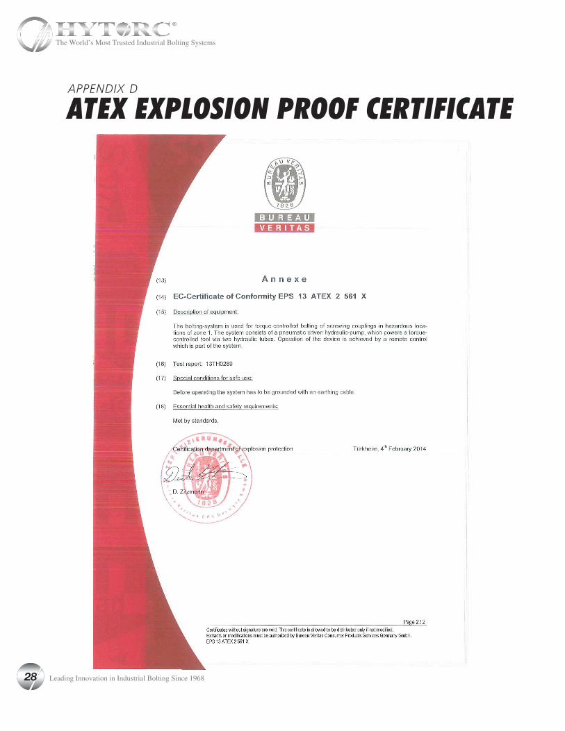
Definition: HYTORC hydraulic bolting system, suitable for hazardous areas:
The bolting system, which can be used in hazardous areas, consists of at least three components:1. Modified pneumatic HYTORC Pump HY-AIR2. Modified twin hose, nominal diameter 6 mm 3. Modified HYTORC Low Clearance Wrench STEALTH and / or HYTORC Square Drive Wrench AVANTI
and / or ICE.
1. Modified component: HYTORC HY-AIR Pneumatic pump must be equipped as follows: a) Solid metal spring on each male and female coupling (between coupler and fitting).
ATTENTION: Only modified HYTORC hydraulic torque wrenches STEALTH, AVANTI and ICE, modified twin hoses (only nominal diameter 6 mm) as well as the modified pneumatic HYTORC Pump JetAir-12 shall be used in hazardous areas!
SECTION VIII
IMPORTANT INSTRUCTIONS FOR ATEX CERTIFIED PNEUMATIC PUMPS FOR EXPLOSION PROTECTIONThe device can be used in hazardous areas as follows:
Explosion-proof hydraulic torque controlled bolting system
HYTORC Division of UNEX Corp.333 Route 17 NorthMahwah, New Jersey 07430 U.S.A.
EPS 13 ATEX 2 561 XEX II 2 G EX c IIB T4CE
15 Leading Innovation in Industrial Bolting Since 1968
The World’s Most Trusted Industrial Bolting Systems
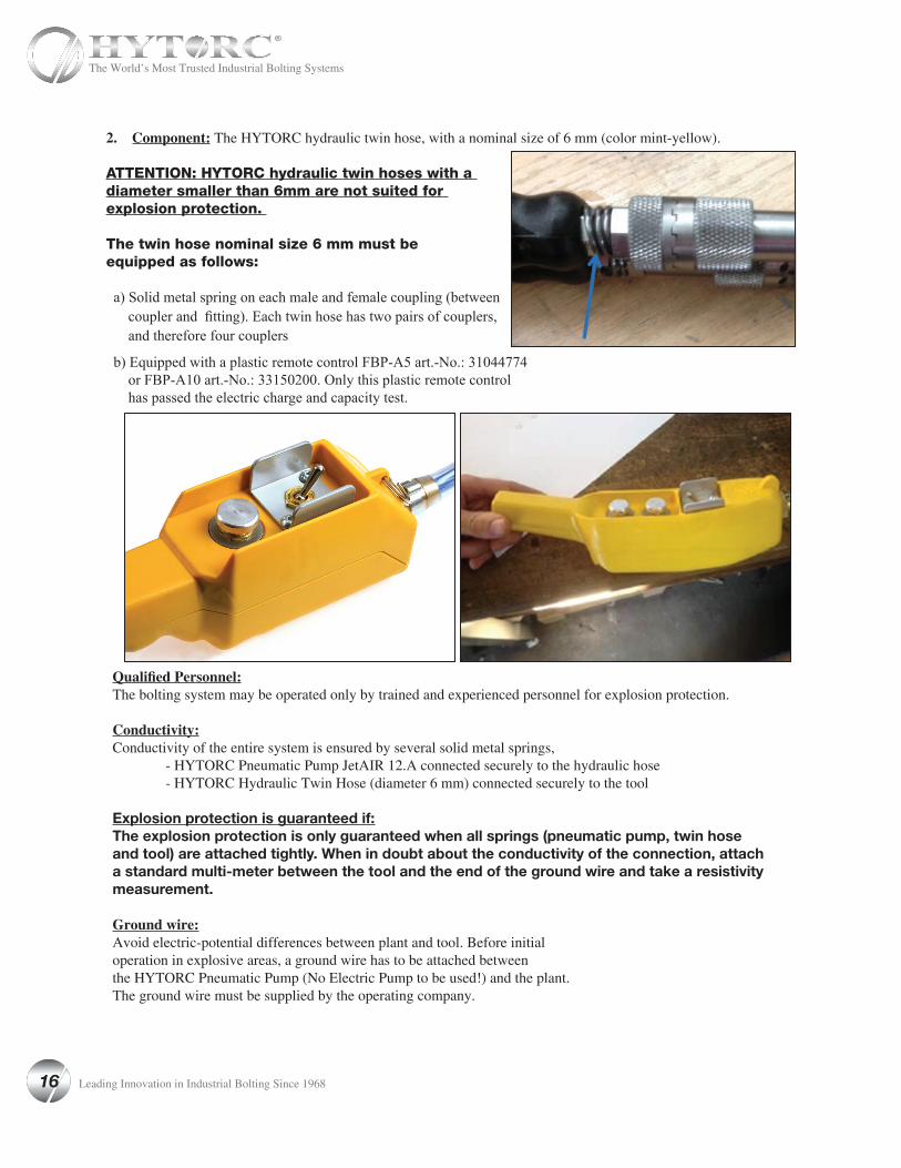
2. Component: The HYTORC hydraulic twin hose, with a nominal size of 6 mm (color mint-yellow).
ATTENTION: HYTORC hydraulic twin hoses with a diameter smaller than 6mm are not suited for explosion protection.
The twin hose nominal size 6 mm must be equipped as follows:
a) Solid metal spring on each male and female coupling (between coupler and fitting). Each twin hose has two pairs of couplers, and therefore four couplers
b) Equipped with a plastic remote control FBP-A5 art.-No.: 31044774 or FBP-A10 art.-No.: 33150200. Only this plastic remote control has passed the electric charge and capacity test.
Qualified Personnel:The bolting system may be operated only by trained and experienced personnel for explosion protection.
Conductivity:Conductivity of the entire system is ensured by several solid metal springs, - HYTORC Pneumatic Pump JetAIR 12.A connected securely to the hydraulic hose - HYTORC Hydraulic Twin Hose (diameter 6 mm) connected securely to the tool
Explosion protection is guaranteed if:The explosion protection is only guaranteed when all springs (pneumatic pump, twin hose and tool) are attached tightly. When in doubt about the conductivity of the connection, attach a standard multi-meter between the tool and the end of the ground wire and take a resistivity measurement.
Ground wire:Avoid electric-potential differences between plant and tool. Before initial operation in explosive areas, a ground wire has to be attached between the HYTORC Pneumatic Pump (No Electric Pump to be used!) and the plant. The ground wire must be supplied by the operating company.
16 Leading Innovation in Industrial Bolting Since 1968
The World’s Most Trusted Industrial Bolting Systems
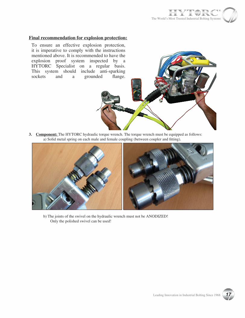
Final recommendation for explosion protection:
3. Component: The HYTORC hydraulic torque wrench. The torque wrench must be equipped as follows: a) Solid metal spring on each male and female coupling (between coupler and fitting). b) The joints of the swivel on the hydraulic wrench must not be ANODIZED! Only the polished swivel can be used!
To ensure an effective explosion protection, it is imperative to comply with the instructions mentioned above. It is recommended to have the explosion proof system inspected by a HYTORC Specialist on a regular basis. This system should include anti-sparking sockets and a grounded flange.
17 Leading Innovation in Industrial Bolting Since 1968
The World’s Most Trusted Industrial Bolting Systems
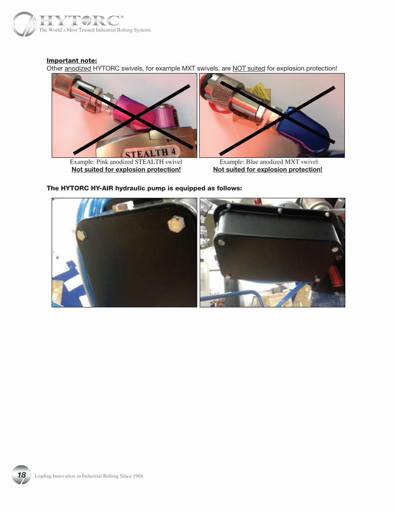
Important note:Other anodized HYTORC swivels, for example MXT swivels, are NOT suited for explosion protection!
Example: Pink anodized STEALTH swivel Example: Blue anodized MXT swivel Not suited for explosion protection! Not suited for explosion protection!
The HYTORC HY-AIR hydraulic pump is equipped as follows:
18 Leading Innovation in Industrial Bolting Since 1968
The World’s Most Trusted Industrial Bolting Systems
SECTION IX
PREVENTIVE MAINTENANCE Preventive Maintenance -Hydraulic Power PacksHYTORC Hydraulic Power Packs are precision-built units and, as such, do require a certain amount of care and maintenance.
• Hydraulic Oil
Oil should be completely changed after every 40 hours of operation, or at least twice a year. Always make sure the reservoir is filled with fluid. If additional oil is required, use only high-grade hydraulic oil.
• Quick-Disconnects
Fittings should be checked periodically for leaks. Dirt or foreign materiais should be kept away from fittings. Clean before use.
• Hydraulic Gauge
Some gauges are liquid filled. Should this liquid level drop, it indicates external leakage, and replacement is necessary. Should the gauge fill with hydraulic oil, it indicates internal failure and it should be discarded.
• Filter on Pump
The filter should be replaced twice a year in normal use and more often if the pump is used daily or in a dirty, harsh environment.
• Remote Control
(Air Unit) The air line to the remote control unit should be checked for obstructions or kinks in the line periodically. If there is a bend or break in the line, it must be replaced. The spring-loaded buttons on the remote handle should bechecked in the event of operating difficulties. (Electric Unit) The rocker switch should be checked periodically if any indication of problems exist.
• Air Valve
This valve should be checked twice a year.
• Brushes and Brush Holders
(Electric Unit) Check and replace, if worn.
• Armature
(Electric Unit) Check yearly.
19 Leading Innovation in Industrial Bolting Since 1968
The World’s Most Trusted Industrial Bolting Systems
SECTION X
TROUBLESHOOTING
SYMPTOM PROBABLE CAUSE REQUIRED ACTIONGauge shows pressure build-up but the tool will not cycle
1. Couplings loose or inoperative
2. Solenoid inoperative
1. Tighten and/or replace couplings. Use Test #1 listed below to isolate problem.
2. Check using test #2 below. If solenoid is bad, replace.
Cylinder will not retract. 1. See above
2. Voltage to electric pump is too low to line drop or inadequate amperage is available.
3. Linkage between piston rod and drive arms are broken.
1. See Above
2. Get shorter extension cord or upgrade to 12AWG, 25 amp rating or better. If shop power is adequate, draw power from welding machine or cal rod transformer.
3. Replace parts as necessary.
Cylinder pressure will not build. 1. Oil blow by in tool (Piston seal leak, blown O-ring, cracked piston)
2. Pump Problem
1. Replace defective parts. SHOP JOB
2. Check to see if sub-plate is worn by; a) Remove screws from pump motor to reservoir, slide Pump motor to the side, turn pump on and while holding down on the button, put your finger on the dump tube (round tube under the directional control valve) - if you feel pressure, then replace the sub-plate and shear seals.
2A. Check to see if you have leaks from the external relief valve and the 2 oil line connections (bottom of relief valve and connection into pump body’s other end) of oil line. If leaking, retighten with 9/16” open end wrench. SHOP JOB
2B. If pump sounds like a lot of pebbles in a tin can, the problem may be a worn motor coupling Remove motor from base plate - using a pair of needle nose pliers remove the motor coupling - if worn, replace. SHOP JOB
2C. AIR PUMPS - Faulty Air Valve due to exces-sive moisture and/or dirt in air supply. Disassemble air valve and wipe any residue from air valve piston - spray brake cleaner into air valve body, dry thoroughly. Disassemble all small air lines and blow out with compressed air. Lubricate both air valve piston and body with hydraulic oil (sparingly) and reassemble. SHOP JOB
2D. Air pumps - Faulty remote control valve cartridge. Replace.
20 Leading Innovation in Industrial Bolting Since 1968
The World’s Most Trusted Industrial Bolting Systems
SYMPTOM PROBABLE CAUSE REQUIRED ACTIONCylinder/Tool leaks 1. Safety relief valve on swivel has lifted.
2. Blown O-ring in cylinder
3. Defective gland seal.
lA. Tighten all hose and couplers. If leak continues, adjust safety setting - Test #4
1B. Check to see if the system is properly plumbed by running test #5 (high pressure on retract side will lift the safety relief valve)
2. Replace O-Ring with proper high pressure O-Ring. SHOP JOB
3. Replace gland seal. SHOP JOB
Tool operates backwards 1. Couplings reversed
2. Multiple hoses in even numbers
1. Run test #5. Replumb system as necessary.
2. As plumbed, HYTORC hoses may only be joined together in odd numbers ONLY. If it is necessary to use 2,4,6 hoses - make an adapter from spare high pressure couplings and nipples.
Ratchet returns with stroke 1. Broken or otherwise inoperable drive segment.
1. Replace drive segment and/or spring. SHOP JOB.
Ratchet will not take successive strokes 1. Broken or otherwise inoperative drive segment I or spring
2. Cylinder not retracting completely
3. Linkage between piston rod and drive plates is broken
1. Replace drive segment and/or spring. SHOP JOB
2. Remove tool from nut and cycle freely for sev-eral strokes. If problem persists, check pawls.
2A. Operator not allowing adequate time for cylin-der to retract fully.
3. Replace parts as necessary - SHOP JOB.
Tool locks onto nut 1. Drive segment is loaded when the tool is max’d out in torque
2. Tool is operating backwards
3. Tool is wedged under a fixed object
1. Press advance button on remote and build pres-sure - continue to press down on remote while pulling back on one of the accuracy assurance levers - release remote while continuing to hold back on levers
2. Push advance button down - tool should immedi-ately fall free- Run test #5
3. Remove shroud from around ratchet. Using any tool available, pry the drive segment out of the ratchet and at the same time pull back on the accuracy assurance levers. Tool should swing free or burn away the socket or obstruction.
21 Leading Innovation in Industrial Bolting Since 1968
The World’s Most Trusted Industrial Bolting Systems
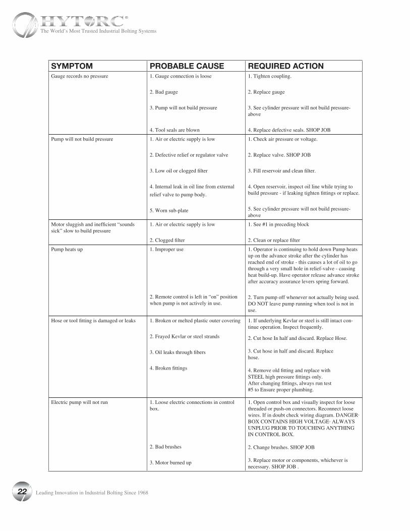
SYMPTOM PROBABLE CAUSE REQUIRED ACTIONGauge records no pressure 1. Gauge connection is loose
2. Bad gauge
3. Pump will not build pressure
4. Tool seals are blown
1. Tighten coupling.
2. Replace gauge
3. See cylinder pressure will not build pressure-above
4. Replace defective seals. SHOP JOB
Pump will not build pressure 1. Air or electric supply is low
2. Defective relief or regulator valve
3. Low oil or clogged filter
4. Internal leak in oil line from external
relief valve to pump body.
5. Worn sub-plate
1. Check air pressure or voltage.
2. Replace valve. SHOP JOB
3. Fill reservoir and clean filter.
4. Open reservoir, inspect oil line while trying to build pressure - if leaking tighten fittings or replace.
5. See cylinder pressure will not build pressure-above
Motor sluggish and inefficient “sounds sick” slow to build pressure
1. Air or electric supply is low
2. Clogged filter
1. See #1 in preceding block
2. Clean or replace filter
Pump heats up 1. Improper use
2. Remote control is left in “on” position when pump is not actively in use.
1. Operator is continuing to hold down Pump heats up on the advance stroke after the cylinder has reached end of stroke - this causes a lot of oil to go through a very small hole in relief-valve - causing heat build-up. Have operator release advance stroke after accuracy assurance levers spring forward.
2. Turn pump off whenever not actually being used. DO NOT leave pump running when tool is not in use.
Hose or tool fitting is damaged or leaks 1. Broken or melted plastic outer covering
2. Frayed Kevlar or steel strands
3. Oil leaks through fibers
4. Broken fittings
1. If underlying Kevlar or steel is still intact con-tinue operation. Inspect frequently.
2. Cut hose In half and discard. Replace Hose.
3. Cut hose in half and discard. Replacehose.
4. Remove old fitting and replace withSTEEL high pressure fittings only.After changing fittings, always run test#5 to Ensure proper plumbing.
Electric pump will not run 1. Loose electric connections in control box.
2. Bad brushes
3. Motor burned up
1. Open control box and visually inspect for loose threaded or push-on connectors. Reconnect loose wires. If in doubt check wiring diagram. DANGER· BOX CONTAINS HIGH VOLTAGE· ALWAYS UNPLUG PRIOR TO TOUCHING ANYTHING IN CONTROL BOX.
2. Change brushes. SHOP JOB
3. Replace motor or components, whichever is necessary. SHOP JOB .
22 Leading Innovation in Industrial Bolting Since 1968
The World’s Most Trusted Industrial Bolting Systems
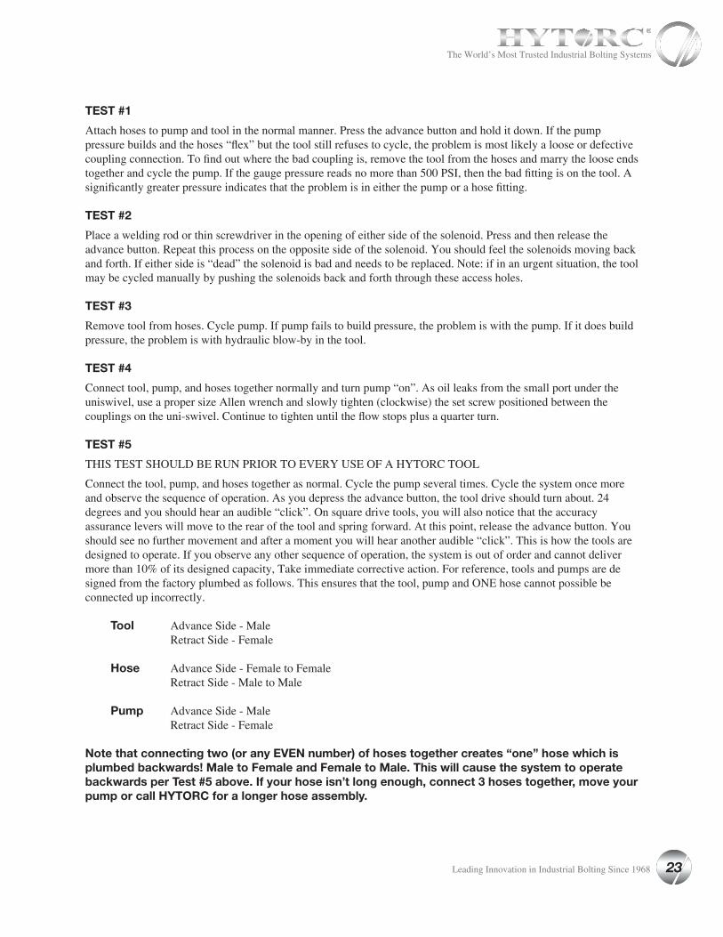
TEST #1
Attach hoses to pump and tool in the normal manner. Press the advance button and hold it down. If the pump pressure builds and the hoses “flex” but the tool still refuses to cycle, the problem is most likely a loose or defective coupling connection. To find out where the bad coupling is, remove the tool from the hoses and marry the loose ends together and cycle the pump. If the gauge pressure reads no more than 500 PSI, then the bad fitting is on the tool. A significantly greater pressure indicates that the problem is in either the pump or a hose fitting.
TEST #2
Place a welding rod or thin screwdriver in the opening of either side of the solenoid. Press and then release the advance button. Repeat this process on the opposite side of the solenoid. You should feel the solenoids moving back and forth. If either side is “dead” the solenoid is bad and needs to be replaced. Note: if in an urgent situation, the tool may be cycled manually by pushing the solenoids back and forth through these access holes.
TEST #3
Remove tool from hoses. Cycle pump. If pump fails to build pressure, the problem is with the pump. If it does build pressure, the problem is with hydraulic blow-by in the tool.
TEST #4
Connect tool, pump, and hoses together normally and turn pump “on”. As oil leaks from the small port under the uniswivel, use a proper size Allen wrench and slowly tighten (clockwise) the set screw positioned between the couplings on the uni-swivel. Continue to tighten until the flow stops plus a quarter turn.
TEST #5
THIS TEST SHOULD BE RUN PRIOR TO EVERY USE OF A HYTORC TOOL
Connect the tool, pump, and hoses together as normal. Cycle the pump several times. Cycle the system once more and observe the sequence of operation. As you depress the advance button, the tool drive should turn about. 24 degrees and you should hear an audible “click”. On square drive tools, you will also notice that the accuracy assurance levers will move to the rear of the tool and spring forward. At this point, release the advance button. You should see no further movement and after a moment you will hear another audible “click”. This is how the tools are designed to operate. If you observe any other sequence of operation, the system is out of order and cannot deliver more than 10% of its designed capacity, Take immediate corrective action. For reference, tools and pumps are designed from the factory plumbed as follows. This ensures that the tool, pump and ONE hose cannot possible be connected up incorrectly.
Tool Advance Side - Male Retract Side - Female
Hose Advance Side - Female to Female Retract Side - Male to Male
Pump Advance Side - Male Retract Side - Female
Note that connecting two (or any EVEN number) of hoses together creates “one” hose which is plumbed backwards! Male to Female and Female to Male. This will cause the system to operate backwards per Test #5 above. If your hose isn’t long enough, connect 3 hoses together, move your pump or call HYTORC for a longer hose assembly.
23 Leading Innovation in Industrial Bolting Since 1968
The World’s Most Trusted Industrial Bolting Systems
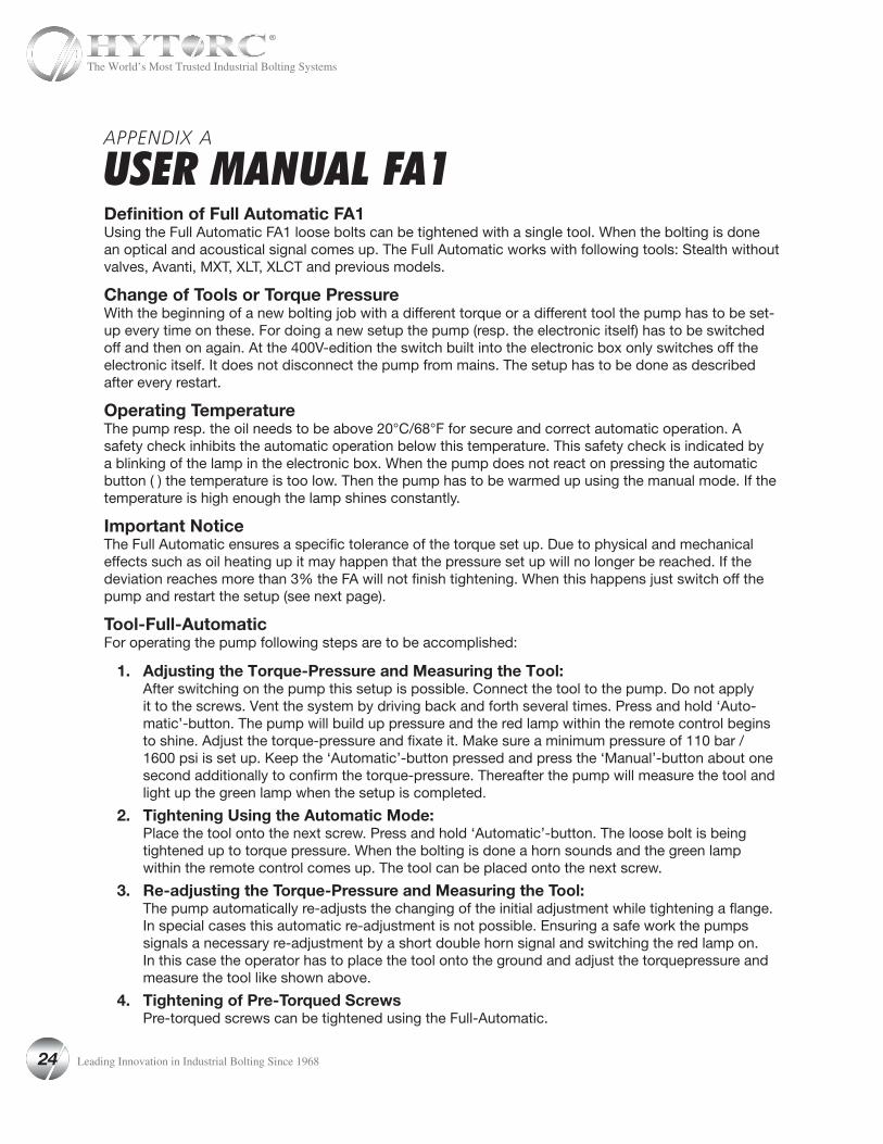
APPENDIX A
USER MANUAL FA1Definition of Full Automatic FA1Using the Full Automatic FA1 loose bolts can be tightened with a single tool. When the bolting is done an optical and acoustical signal comes up. The Full Automatic works with following tools: Stealth without valves, Avanti, MXT, XLT, XLCT and previous models.
Change of Tools or Torque PressureWith the beginning of a new bolting job with a different torque or a different tool the pump has to be set-up every time on these. For doing a new setup the pump (resp. the electronic itself) has to be switched off and then on again. At the 400V-edition the switch built into the electronic box only switches off theelectronic itself. It does not disconnect the pump from mains. The setup has to be done as described after every restart.
Operating TemperatureThe pump resp. the oil needs to be above 20°C/68°F for secure and correct automatic operation. A safety check inhibits the automatic operation below this temperature. This safety check is indicated by a blinking of the lamp in the electronic box. When the pump does not react on pressing the automatic button ( ) the temperature is too low. Then the pump has to be warmed up using the manual mode. If the temperature is high enough the lamp shines constantly.
Important NoticeThe Full Automatic ensures a specific tolerance of the torque set up. Due to physical and mechanical effects such as oil heating up it may happen that the pressure set up will no longer be reached. If the deviation reaches more than 3% the FA will not finish tightening. When this happens just switch off the pump and restart the setup (see next page).
Tool-Full-AutomaticFor operating the pump following steps are to be accomplished:
1. Adjusting the Torque-Pressure and Measuring the Tool: After switching on the pump this setup is possible. Connect the tool to the pump. Do not apply it to the screws. Vent the system by driving back and forth several times. Press and hold ‘Auto-matic’-button. The pump will build up pressure and the red lamp within the remote control begins to shine. Adjust the torque-pressure and fixate it. Make sure a minimum pressure of 110 bar / 1600 psi is set up. Keep the ‘Automatic’-button pressed and press the ‘Manual’-button about one second additionally to confirm the torque-pressure. Thereafter the pump will measure the tool and light up the green lamp when the setup is completed.
2. Tightening Using the Automatic Mode: Place the tool onto the next screw. Press and hold ‘Automatic’-button. The loose bolt is being tightened up to torque pressure. When the bolting is done a horn sounds and the green lamp within the remote control comes up. The tool can be placed onto the next screw.
3. Re-adjusting the Torque-Pressure and Measuring the Tool: The pump automatically re-adjusts the changing of the initial adjustment while tightening a flange. In special cases this automatic re-adjustment is not possible. Ensuring a safe work the pumps signals a necessary re-adjustment by a short double horn signal and switching the red lamp on. In this case the operator has to place the tool onto the ground and adjust the torquepressure and measure the tool like shown above.
4. Tightening of Pre-Torqued Screws Pre-torqued screws can be tightened using the Full-Automatic.
24 Leading Innovation in Industrial Bolting Since 1968
The World’s Most Trusted Industrial Bolting Systems

APPENDIX B
USER MANUAL FA4Definition of Full Automatic FA4Using the Full Automatic FA4, loose bolts can be tightened with up to four tools. When the bolting is done an optical and acoustical signal comes up.
Changing Tools or Torque PressureAt the beginning of a new bolting job with different torque or different tools the power packhas to be readjusted. To do this you have to switch off the power pack and switch it onagain. After restarting the power pack you have to set it up as given below.
Working with the 4-Tool-Full-Automatic
1. Adjusting the torque and measuring the tools: Before starting a bolting job you have to setup the torque pressure and let the power pack measure the tools.
• Connect the tools to the pump. Do not apply them to the screws; let them lay loosely on the floor. Vent the system by driving back and forth several times.
• Press and hold ‘Automatic’-button ( ). The power pack builds up pressure and the red LED within the remote control begins to shine.
• Adjust the torque pressure and fixate it.
• Keep the ‘Automatic’-button pressed. For approx. one second press the ‘Manual’-button () additionally. By doing so you save the torque pressure into the power pack. Still keep the Automatic-button pressed.
• The power pack will now measure the tools. Therefor it will advance and retract them several times.
Once the setup is done the green light in the remote control lights up.
2. Tightening using the automatic mode:• Place the tools onto the bolts.
• Press and hold ‘Automatic’-button ( ). The loose bolts are beeing pre-tightened first. Once the system detects that all bolts are pre-tightened, the system starts to tighten the bolts up to torque pressure.
• When the bolting is done a horn sounds and the green LED within the remote• control lights up.
• The tools can be placed onto the next bolts.
3. Tightening of pre-torqued screws Pre-torqued bolts can be tightened using the Full-Automatic. The built-in safety-check detects loose bolts and pre-tightens them first.
25 Leading Innovation in Industrial Bolting Since 1968
The World’s Most Trusted Industrial Bolting Systems
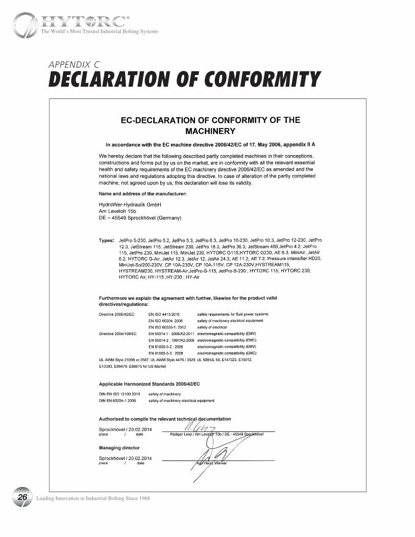
APPENDIX C
DECLARATION OF CONFORMITY
26 Leading Innovation in Industrial Bolting Since 1968
The World’s Most Trusted Industrial Bolting Systems
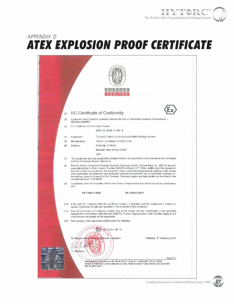
APPENDIX D
ATEX EXPLOSION PROOF CERTIFICATE
27 Leading Innovation in Industrial Bolting Since 1968
The World’s Most Trusted Industrial Bolting Systems
APPENDIX D
ATEX EXPLOSION PROOF CERTIFICATE
28 Leading Innovation in Industrial Bolting Since 1968
The World’s Most Trusted Industrial Bolting Systems
Azolla ZS (All grades) Revision Date 11-1-2013
Page 1 of 5 www.totalluricantsusa.com
MATERIAL SAFETY DATA SHEET
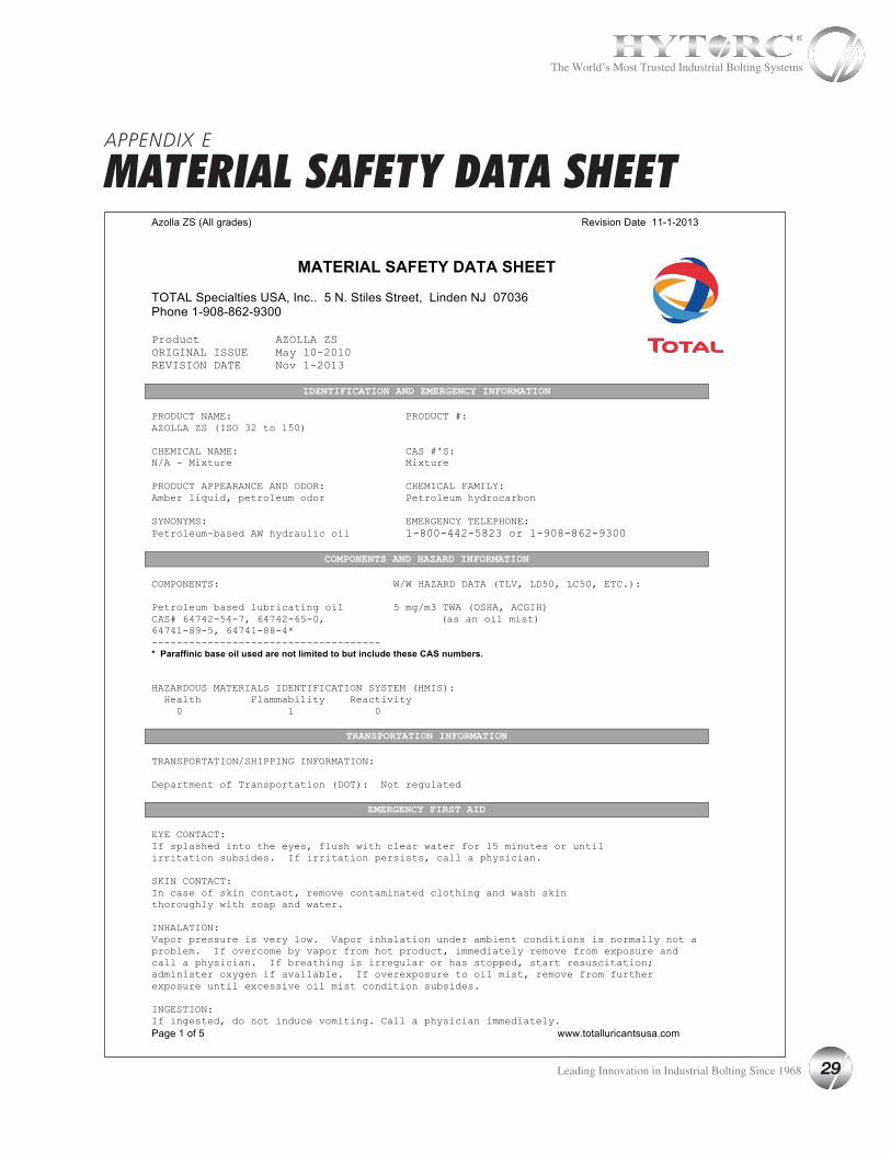
TOTAL Specialties USA, Inc.. 5 N. Stiles Street, Linden NJ 07036 Phone 1-908-862-9300 Product AZOLLA ZS ORIGINAL ISSUE May 10-2010 REVISION DATE Nov 1-2013
IDENTIFICATION AND EMERGENCY INFORMATION PRODUCT NAME: PRODUCT #: AZOLLA ZS (ISO 32 to 150) CHEMICAL NAME: CAS #'S: N/A - Mixture Mixture PRODUCT APPEARANCE AND ODOR: CHEMICAL FAMILY: Amber liquid, petroleum odor Petroleum hydrocarbon SYNONYMS: EMERGENCY TELEPHONE: Petroleum-based AW hydraulic oil 1-800-442-5823 or 1-908-862-9300
COMPONENTS AND HAZARD INFORMATION COMPONENTS: W/W HAZARD DATA (TLV, LD50, LC50, ETC.): Petroleum based lubricating oil 5 mg/m3 TWA (OSHA, ACGIH) CAS# 64742-54-7, 64742-65-0, (as an oil mist) 64741-89-5, 64741-88-4* ------------------------------------- * Paraffinic base oil used are not limited to but include these CAS numbers. HAZARDOUS MATERIALS IDENTIFICATION SYSTEM (HMIS): Health Flammability Reactivity 0 l 0
TRANSPORTATION INFORMATION TRANSPORTATION/SHIPPING INFORMATION: Department of Transportation (DOT): Not regulated
EMERGENCY FIRST AID EYE CONTACT: If splashed into the eyes, flush with clear water for l5 minutes or until irritation subsides. If irritation persists, call a physician. SKIN CONTACT: In case of skin contact, remove contaminated clothing and wash skin thoroughly with soap and water. INHALATION: Vapor pressure is very low. Vapor inhalation under ambient conditions is normally not a problem. If overcome by vapor from hot product, immediately remove from exposure and call a physician. If breathing is irregular or has stopped, start resuscitation; administer oxygen if available. If overexposure to oil mist, remove from further exposure until excessive oil mist condition subsides. INGESTION: If ingested, do not induce vomiting. Call a physician immediately.
APPENDIX E
MATERIAL SAFETY DATA SHEET
29 Leading Innovation in Industrial Bolting Since 1968
The World’s Most Trusted Industrial Bolting Systems
Azolla ZS (All grades) Revision Date 11-1-2013
Page 2 of 5 www.totalluricantsusa.com
FIRE AND EXPLOSION HAZARD INFORMATION FLASH POINT (MINIMUM): AUTOIGNITION TEMPERATURE: 179°C (355°F) Test method: COC N/E NATIONAL FIRE PROTECTION ASSOCIATION (NFPA) - HAZARD IDENTIFICATION: Health Flammability Reactivity 0 l 0 FLAMMABLE OR EXPLOSIVE LIMITS (approximate percent by volume in air): Estimated values: lower: N/E upper: N/E EXTINGUISHING MEDIA AND FIRE FIGHTING PROCEDURES: Foam, water spray (fog), dry chemical, carbon dioxide and vaporizing liquid type extinguishing agents may all be suitable for extinguishing fires involving this type product, depending on size or potential size of fire and circumstances related to the situation. Plan fire protection and response strategy through consultation with local fire protection authorities or appropriate specialists. The following procedures for this type of product are based on the recommendations in the National Fire Protection Association's "Fire Protection Guide on Hazardous Materials", Eighth Edition (l984): Use water spray, dry chemical, foam, or carbon dioxide. Water or foam my cause frothing. Use water to keep fire-exposed containers cool. Water froth may be used to flush spills away form exposure. Minimize breathing gases, vapor, fumes, or decomposition products. Use supplied-air breathing equipment for enclosed or confined spaces or as otherwise needed. UNUSUAL FIRE AND EXPLOSION HAZARDS: n/a "EMPTY" CONTAINER WARNING: Empty containers retain residue (liquid or vapor) and can be dangerous. DO NOT PRESSURIZE, WELD, CUT BRAZE, SOLDER, DRILL, GRIND OR EXPOSE SUCH CONTAINERS TO HEAT, FLAME, SPARKS, OR OTHER SOURCES OF IGNITION; THEY MAY EXPLODE AND CAUSE INJURY OR DEATH. Do not attempt to clean since residue is difficult to remove. "Empty" drums should be completely drained, properly bunged, and returned to a drum reconditioner. All other containers should be disposed of in an environmentally safe manner and in accordance with government regulations. For work on tanks refer to Occupational Safety and Health Administration regulations, ANSI Z49.l, and other governmental and industrial references pertaining to cleaning, repairing, welding, or other contemplated operations.
HEALTH AND HAZARD INFORMATION EXPOSURE LIMIT FOR TOTAL PRODUCT: Monitor data listed in the Components and Hazard Information section. VARIABILITY AMONG INDIVIDUALS: Health studies have shown that many petroleum hydrocarbons and synthetic lubricants pose potential human health risks which vary from person to person. As a precaution, exposure to liquids, vapors, mists, or fumes should be minimized. EFFECTS OF OVEREXPOSURE (Signs and symptoms of exposure): Prolonged or repeated skin contact with this product tends to remove skin oils possibly leading to irritation and dermatitis. Product contacting the eye may cause irritation. Product has a low order of oral and dermal toxicity. Possible aspiration hazard. Induced vomiting may cause aspiration of product into the lungs. (See Emergency First Aid Section).
APPENDIX E
MATERIAL SAFETY DATA SHEET
30 Leading Innovation in Industrial Bolting Since 1968
The World’s Most Trusted Industrial Bolting Systems
Azolla ZS (All grades) Revision Date 11-1-2013
Page 3 of 5 www.totalluricantsusa.com
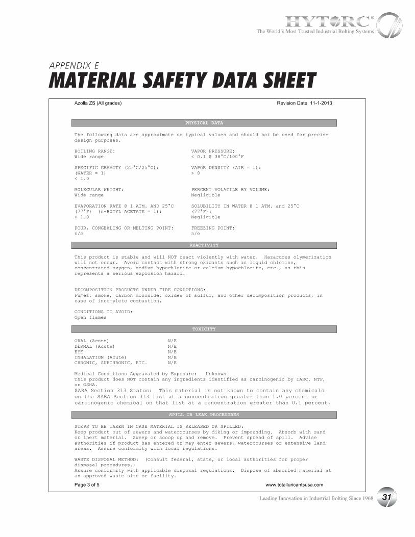
PHYSICAL DATA The following data are approximate or typical values and should not be used for precise design purposes. BOILING RANGE: VAPOR PRESSURE: Wide range < 0.l @ 38°C/l00°F SPECIFIC GRAVITY (25°C/25°C): VAPOR DENSITY (AIR = l): (WATER = l) > 8 < l.0 MOLECULAR WEIGHT: PERCENT VOLATILE BY VOLUME: Wide range Negligible EVAPORATION RATE @ l ATM. AND 25°C SOLUBILITY IN WATER @ l ATM. and 25°C (77°F) (n-BUTYL ACETATE = l): (77°F): < l.0 Negligible POUR, CONGEALING OR MELTING POINT: FREEZING POINT: n/e n/e
REACTIVITY This product is stable and will NOT react violently with water. Hazardous olymerization will not occur. Avoid contact with strong oxidants such as liquid chlorine, concentrated oxygen, sodium hypochlorite or calcium hypochlorite, etc., as this represents a serious explosion hazard. DECOMPOSITION PRODUCTS UNDER FIRE CONDITIONS: Fumes, smoke, carbon monoxide, oxides of sulfur, and other decomposition products, in case of incomplete combustion. CONDITIONS TO AVOID: Open flames
TOXICITY ORAL (Acute) N/E DERMAL (Acute) N/E EYE N/E INHALATION (Acute) N/E CHRONIC, SUBCHRONIC, ETC. N/E Medical Conditions Aggravated by Exposure: Unknown This product does NOT contain any ingredients identified as carcinogenic by IARC, NTP, or OSHA. SARA Section 313 Status: This material is not known to contain any chemicals on the SARA Section 313 list at a concentration greater than 1.0 percent or carcinogenic chemical on that list at a concentration greater than 0.1 percent.
SPILL OR LEAK PROCEDURES STEPS TO BE TAKEN IN CASE MATERIAL IS RELEASED OR SPILLED: Keep product out of sewers and watercourses by diking or impounding. Absorb with sand or inert material. Sweep or scoop up and remove. Prevent spread of spill. Advise authorities if product has entered or may enter sewers, watercourses or extensive land areas. Assure conformity with local regulations. WASTE DISPOSAL METHOD: (Consult federal, state, or local authorities for proper disposal procedures.) Assure conformity with applicable disposal regulations. Dispose of absorbed material at an approved waste site or facility.
APPENDIX E
MATERIAL SAFETY DATA SHEET
31 Leading Innovation in Industrial Bolting Since 1968
The World’s Most Trusted Industrial Bolting Systems
Azolla ZS (All grades) Revision Date 11-1-2013
Page 4 of 5 www.totalluricantsusa.com
PROTECTION AND PRECAUTIONS
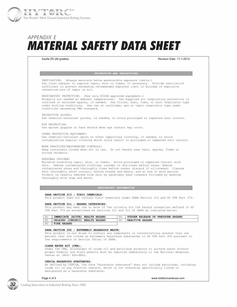
VENTILATION: (Always maintain below permissible exposure limits.) Use local exhaust to capture vapor, mist or fumes, if necessary. Provide ventilation sufficient to prevent exceeding recommended exposure limit or buildup of explosive concentrations of vapor in air. RESPIRATORY PROTECTION: (Use only NIOSH approved equipment.) Normally not needed at ambient temperatures. Use supplied air respiratory protection in confined or enclosed spaces, if needed. Use filter, dust, fume, or mist respirator type under misting conditions. Use can or cartridge; gas or vapor respirator type under conditions exceeding TWA standard. PROTECTIVE GLOVES: Use chemical-resistant gloves, if needed, to avoid prolonged or repeated skin contact. EYE PROTECTION: Use splash goggles or face shield when eye contact may occur. OTHER PROTECTIVE EQUIPMENT: Use chemical-resistant apron or other impervious clothing, if needed, to avoid contaminating regular clothing which could result in prolonged or repeated skin contact. WORK PRACTICES/ENGINEERING CONTROLS: Keep containers closed when not in use. Do not handle near heat, sparks, flame or strong oxidants. PERSONAL HYGIENE: Minimize breathing vapor, mist, or fumes. Avoid prolonged or repeated contact with skin. Remove contaminated clothing; launder or dry-clean before reuse. Remove contaminated shoes and thoroughly clean before reuse; discard if oil-soaked. Cleanse skin thoroughly after contact, before breaks and meals, and at end of work period. Product is readily removed from skin by waterless hand cleaners followed by washing thoroughly with soap and water.
REGULATORY INFORMATION SARA SECTION 313 - TOXIC CHEMICALS: This product does not contain toxic chemicals under SARA Section 313 and 40 CFR Part 372.
SARA SECTION 311 - HAZARD CATEGORIES: This product may meet one or more of the criteria for the hazard categories defined in 40 CFR Part 370 as established be Sections 311 and 312 of SARA as indicated below:
NO IMMEDIATE (ACUTE) HEALTH HAZARD NO SUDDEN RELEASE OF PRESSURE HAZARD NO DELAYED (CHRONIC) HEALTH HAZARD NO REACTIVE HAZARD NO FIRE HAZARD
SARA SECTION 302 - EXTREMELY HAZARDOUS WASTE: This product is not known to contain any components in concentrations greater than one percent that are listed as Extremely Hazardous Substances in 40 CFR Part 355 pursuant to the requirements of Section 302(a) of SARA.
CLEAN WATER ACT (CWA): Under the CWA, discharges of crude oil and petroleum products to surface water without proper Federal and State permits must be reported immediately to the National Response Center at (800) 424-8802.
CERCLA HAZARDOUS SUBSTANCES: As defined by CERCLA, the term “hazardous substance” does not include petroleum, including crude oil or any fraction thereof, which is not otherwise specifically listed or designated as a hazardous substance.
APPENDIX E
MATERIAL SAFETY DATA SHEET
32 Leading Innovation in Industrial Bolting Since 1968
The World’s Most Trusted Industrial Bolting Systems
Azolla ZS (All grades) Revision Date 11-1-2013
Page 5 of 5 www.totalluricantsusa.com
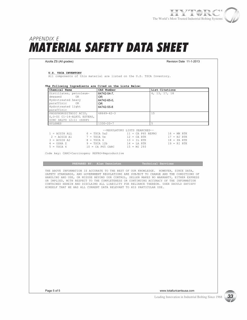
U.S. TSCA INVENTORY All components of this material are listed on the U.S. TSCA Inventory.
The Following Ingredients are Cited on the Lists Below:
Chemical Name CAS Number List Citations Distillates, petroleum-dewaxed OR Hydrotreated heavy paraffinic OR Hydrotreated light paraffinic
64742-54-7, OR 64742-65-0, OR 64742-55-8
4, 13, 17, 18
PHOSPHORODITHOIC ACID, O,O-DI C1-14-ALKYL ESTERS, ZINC SALTS (2:1) (ZDDP)
68649-42-3 15
XYLENES 1330-20-7 5
--REGULATORY LISTS SEARCHED-- 1 = ACGIH ALL 6 = TSCA 5a2 11 = CA P65 REPRO 16 = MN RTK 2 = ACGIH A1 7 = TSCA 5e 12 = CA RTK 17 = NJ RTK 3 = ACGIH A2 8 = TSCA 6 13 = IL RTK 18 = PA RTK 4 = OSHA Z 9 = TSCA 12b 14 = LA RTK 19 = RI RTK 5 = TSCA 4 10 = CA P65 CARC 15 = MI 293
Code key: CARC=Carcinogen; REPRO=Reproductive
PREPARED BY: Alan Denniston Technical Services THE ABOVE INFORMATION IS ACCURATE TO THE BEST OF OUR KNOWLEDGE. HOWEVER, SINCE DATA, SAFETY STANDARDS, AND GOVERNMENT REGULATIONS ARE SUBJECT TO CHANGE AND THE CONDITIONS OF HANDLING AND USE, OR MISUSE BEYOND OUR CONTROL, SELLER MAKES NO WARRANTY, EITHER EXPRESS OR IMPLIED, WITH RESPECT TO THE COMPLETENESS OR CONTINUING ACCURACY OF THE INFORMATION CONTAINED HEREIN AND DISCLAIMS ALL LIABILITY FOR RELIANCE THEREON. USER SHOULD SATISFY HIMSELF THAT HE HAS ALL CURRENT DATA RELEVANT TO HIS PARTICULAR USE.
APPENDIX E
MATERIAL SAFETY DATA SHEET
33 Leading Innovation in Industrial Bolting Since 1968
The World’s Most Trusted Industrial Bolting Systems
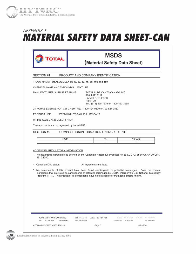
AZOLLA ZS SERIES MSDS TLC.doc Page 1 6/21/2011
MSDS(Material Safety Data Sheet)
SECTION #1 PRODUCT AND COMPANY IDENTIFICATION
TRADE NAME: TOTAL AZOLLA ZS 10, 22, 32, 46, 68, 100 and 150
CHEMICAL NAME AND SYNONYMS: MIXTURE
MANUFACTURER/SUPPLIER’S NAME: TOTAL LUBRICANTS CANADA INC.220, LAFLEUR LASALLE, QUEBEC H8R 4C9Tel.: (514) 595-7579 or 1-800-463-3955
24 HOURS EMERGENCY: Call CHEMTREC 1-800-424-9300 or 703-527-3887
PRODUCT USE: PREMIUM HYDRAULIC LUBRICANT
WHMIS CLASS AND DESCRIPTION -
These products are not regulated by the WHMIS.
SECTION #2 COMPOSITION/INFORMATION ON INGREDIENTS
NOM % No CAS--- -- ---
ADDITIONAL REGULATORY INFORMATION
- No hazardous ingredients as defined by the Canadian Hazardous Products Act (BILL C70) or by OSHA 29 CFR1910.1200.
- Canadian DSL status: All ingredients are listed.
* No components of this product have been found carcinogenic or potential carcinogen. Does not contain ingredients that are listed as carcinogenic or potential carcinogen by OSHA, IARC or the U.S. National Toxicology Program (NTP). This product or its components have no teratogenic or mutagenic effects known.
APPENDIX F
MATERIAL SAFETY DATA SHEET-CAN
34 Leading Innovation in Industrial Bolting Since 1968
The World’s Most Trusted Industrial Bolting Systems
AZOLLA ZS SERIES MSDS TLC.doc Page 2 6/21/2011
SECTION #3 PHYSICAL DATA
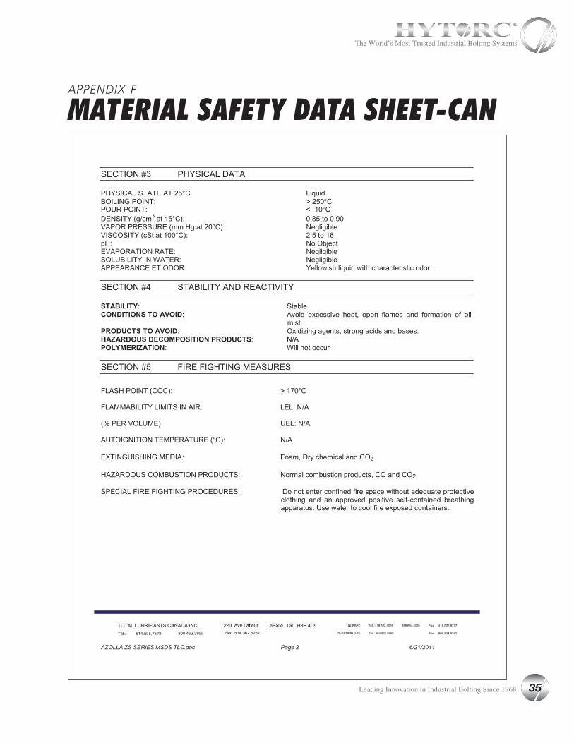
PHYSICAL STATE AT 25°C Liquid BOILING POINT: > 250°CPOUR POINT: < -10°C DENSITY (g/cm3 at 15°C): 0,85 to 0,90VAPOR PRESSURE (mm Hg at 20°C): Negligible VISCOSITY (cSt at 100°C): 2,5 to 16 pH: No ObjectEVAPORATION RATE: Negligible SOLUBILITY IN WATER: NegligibleAPPEARANCE ET ODOR: Yellowish liquid with characteristic odor
SECTION #4 STABILITY AND REACTIVITY
STABILITY: StableCONDITIONS TO AVOID: Avoid excessive heat, open flames and formation of oil
mist.PRODUCTS TO AVOID: Oxidizing agents, strong acids and bases.HAZARDOUS DECOMPOSITION PRODUCTS: N/APOLYMERIZATION: Will not occur
SECTION #5 FIRE FIGHTING MEASURES
FLASH POINT (COC): > 170°C
FLAMMABILITY LIMITS IN AIR: LEL: N/A
(% PER VOLUME) UEL: N/A
AUTOIGNITION TEMPERATURE (°C): N/A
EXTINGUISHING MEDIA: Foam, Dry chemical and CO2
HAZARDOUS COMBUSTION PRODUCTS: Normal combustion products, CO and CO2.
SPECIAL FIRE FIGHTING PROCEDURES: Do not enter confined fire space without adequate protective
clothing and an approved positive self-contained breathing apparatus. Use water to cool fire exposed containers.
APPENDIX F
MATERIAL SAFETY DATA SHEET-CAN
35 Leading Innovation in Industrial Bolting Since 1968
The World’s Most Trusted Industrial Bolting Systems
APPENDIX F
MATERIAL SAFETY DATA SHEET-CAN
AZOLLA ZS SERIES MSDS TLC.doc Page 3 6/21/2011
SECTION #6 TOXICOLOGICAL INFORMATION
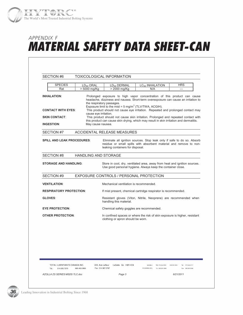
SPECIES LD50 ORAL LD50 DERMAL LC50 INHALATION HRSRat > 5000 mg/Kg > 2000 mg/Kg N/A ---
INHALATION: Prolonged exposure to high vapor concentration of this product can cause
headache, dizziness and nausea. Short-term overexposure can cause an irritation to the respiratory passages.Exposure limit to the mist = 5 mg/m3 (TLV/TWA, ACGIH).
CONTACT WITH EYES: This product should not cause eye irritation. Repeated and prolonged contact may cause eye irritation.
SKIN CONTACT: This product should not cause skin irritation. Prolonged and repeated contact with this product can cause skin drying, which may result in skin irritation and dermatitis.
INGESTION: May cause nausea.
SECTION #7 ACCIDENTAL RELEASE MEASURES
SPILL AND LEAK PROCEDURES: Eliminate all ignition sources. Stop leak only if safe to do so. Absorb residue or small spills with absorbent material and remove to non-leaking containers for disposal.
SECTION #8 HANDLING AND STORAGE
STORAGE AND HANDLING: Store in cool, dry, ventilated area, away from heat and ignition sources.
Use good personal hygiene. Always keep the container close.
SECTION #9 EXPOSURE CONTROLS / PERSONAL PROTECTION
VENTILATION: Mechanical ventilation is recommended.
RESPIRATORY PROTECTION: If mist present, chemical cartridge respirator is recommended.
GLOVES: Resistant gloves (Viton, Nitrile, Neoprene) are recommended when handling this material.
EYE PROTECTION: Chemical safety goggles are recommended.
OTHER PROTECTION: In confined spaces or where the risk of skin exposure is higher, resistant
clothing or apron should be worn.
36 Leading Innovation in Industrial Bolting Since 1968
The World’s Most Trusted Industrial Bolting Systems
APPENDIX F
MATERIAL SAFETY DATA SHEET-CAN
AZOLLA ZS SERIES MSDS TLC.doc Page 4 6/21/2011
SECTION #10 DISPOSAL CONSIDERATIONS
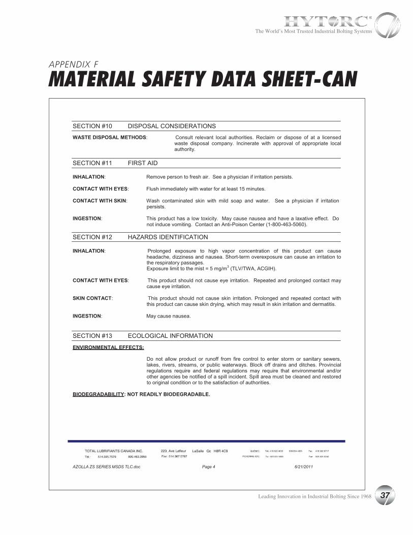
WASTE DISPOSAL METHODS: Consult relevant local authorities. Reclaim or dispose of at a licensed
waste disposal company. Incinerate with approval of appropriate local authority.
SECTION #11 FIRST AID
INHALATION: Remove person to fresh air. See a physician if irritation persists.
CONTACT WITH EYES: Flush immediately with water for at least 15 minutes.
CONTACT WITH SKIN: Wash contaminated skin with mild soap and water. See a physician if irritation
persists.
INGESTION: This product has a low toxicity. May cause nausea and have a laxative effect. Do not induce vomiting. Contact an Anti-Poison Center (1-800-463-5060).
SECTION #12 HAZARDS IDENTIFICATION
INHALATION: Prolonged exposure to high vapor concentration of this product can cause
headache, dizziness and nausea. Short-term overexposure can cause an irritation to the respiratory passages.Exposure limit to the mist = 5 mg/m3 (TLV/TWA, ACGIH).
CONTACT WITH EYES: This product should not cause eye irritation. Repeated and prolonged contact may
cause eye irritation.
SKIN CONTACT: This product should not cause skin irritation. Prolonged and repeated contact with this product can cause skin drying, which may result in skin irritation and dermatitis.
INGESTION: May cause nausea.
SECTION #13 ECOLOGICAL INFORMATION
ENVIRONMENTAL EFFECTS:
Do not allow product or runoff from fire control to enter storm or sanitary sewers, lakes, rivers, streams, or public waterways. Block off drains and ditches. Provincial regulations require and federal regulations may require that environmental and/or other agencies be notified of a spill incident. Spill area must be cleaned and restored to original condition or to the satisfaction of authorities.
BIODEGRADABILITY: NOT READILY BIODEGRADABLE.
37 Leading Innovation in Industrial Bolting Since 1968
The World’s Most Trusted Industrial Bolting Systems
APPENDIX F
MATERIAL SAFETY DATA SHEET-CAN
AZOLLA ZS SERIES MSDS TLC.doc Page 5 6/21/2011
SECTION #14 TRANSPORTATION INFORMATION
TRANSPORTATION (TDG)
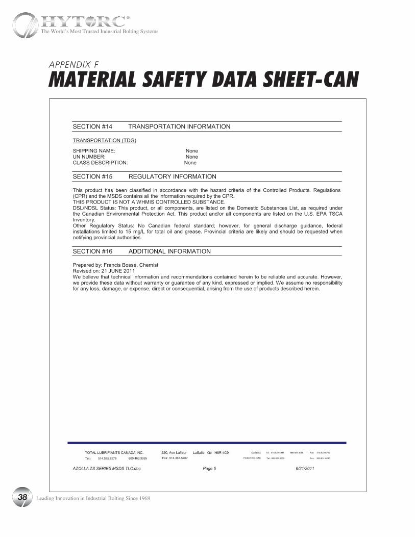
SHIPPING NAME: None UN NUMBER: None CLASS DESCRIPTION: None
SECTION #15 REGULATORY INFORMATION
This product has been classified in accordance with the hazard criteria of the Controlled Products. Regulations(CPR) and the MSDS contains all the information required by the CPR. THIS PRODUCT IS NOT A WHMIS CONTROLLED SUBSTANCE.DSL/NDSL Status: This product, or all components, are listed on the Domestic Substances List, as required under the Canadian Environmental Protection Act. This product and/or all components are listed on the U.S. EPA TSCA Inventory.Other Regulatory Status: No Canadian federal standard; however, for general discharge guidance, federal installations limited to 15 mg/L for total oil and grease. Provincial criteria are likely and should be requested when notifying provincial authorities.
SECTION #16 ADDITIONAL INFORMATION
Prepared by: Francis Bossé, ChemistRevised on: 21 JUNE 2011We believe that technical information and recommendations contained herein to be reliable and accurate. However, we provide these data without warranty or guarantee of any kind, expressed or implied. We assume no responsibility for any loss, damage, or expense, direct or consequential, arising from the use of products described herein.
38 Leading Innovation in Industrial Bolting Since 1968
The World’s Most Trusted Industrial Bolting Systems


Worldwide Warranty, Service & Expertise!
Being #1 is no coincidence!
Division UNEX Corporation333 State Route 17N, Mahwah, New Jersey 07430 U.S.A.
800-FOR-HYTORC • Tel: 201-512-9500 • E-Mail: [email protected] • Web: www.hytorc.com
We are always within 1 hour from you!
CALL: 1-800-FOR-
Find your nearest HYTORC at www.hytorc.com/worldwide
MAN-HY-115/230-2015-1


![Hydraulic Hoses - Dasa International S.r.l.dasa-it.com/files/tubi idraulici [hydraulic hoses].pdf · Hydraulic Hoses with multispiral steel wire reinforcement Pagina Page HH4SP-XX-X](https://static.fdocuments.net/doc/165x107/5e9e573cccf6552bb75611bf/hydraulic-hoses-dasa-international-srldasa-itcomfilestubi-idraulici-hydraulic.jpg)


