HYDRAULIC PRESSURE SWITCHES - kda132.com · interest in the bleeding of air in the system. In 1987...
12
865 Number 61 March 2007, HYDRAULIC PRESSURE SWITCHES These rather essential little gadgets do fail from time to time which to people of some common sense is slightly alarming. Apparently to the great unwashed it is no problem. These switches or possibly more correctly, sensors, let you know if the pressure in the accumulators in your car fall below an acceptable level. At left is a picture of two iterations of the pressure switch. The upper one is an early version using a spade terminal and the latter the push over terminal. Inside they were almost identical except with some improvements in insulation. At repose the switches are earthed i.e. there is a direct circuit through the switch from the terminal to earth. This lights the lamp. Break the circuit and the light goes out – ingenious???? One of the things that make writing these pages difficult is that I seem to be addressing a cast ranging from specialists of 40 years standing across to 17 year old lads dying to know everything they can about a Rolls-Royce. So if you will bear with me – or turn the page!!! Here it is all laid out clean and nice. Basically the switch screws into the high pressure side of the accumulator valve chest (that’s is the function of the bit on the left) and the gubbins that follows left to right makes a circuit to the terminal on the bit at the right. Some owners still do not realise that post Cloud days every Silver Shadow or derivative to have brakes needs at least the engine running (assuming it has good pumps) or well charged accumulators – charged that is with nitrogen! If as some extraordinary variation on the species of owner seem to practice, running on the pumps with completely depleted accumulators, (of nitrogen)
Transcript of HYDRAULIC PRESSURE SWITCHES - kda132.com · interest in the bleeding of air in the system. In 1987...

865
Number 61 March 2007,
HYDRAULIC PRESSURE SWITCHES
These rather essential little gadgets do fail from time to time which to people of some common sense is slightly alarming. Apparently to the great unwashed it is no problem. These switches or possibly more correctly, sensors, let you know if the pressure in the accumulators in your car fall below an acceptable level. At left is a picture of two iterations of the pressure switch. The upper one is an early version using a spade terminal and the latter the push over terminal. Inside they were almost identical except with some improvements in insulation. At repose the switches are earthed i.e. there is a direct circuit through the switch from the terminal to earth. This lights the lamp. Break the circuit and the light goes out – ingenious????
One of the things that make writing these pages difficult is that I seem to be addressing a cast ranging from specialists of 40 years standing across to 17 year old lads dying to know everything they can about a Rolls-Royce. So if you will bear with me – or turn the page!!!
Here it is all laid out clean and nice. Basically the switch screws into the high pressure side of the accumulator valve chest (that’s is the function of the bit on the left) and the gubbins that follows left to right makes a circuit to the terminal on the bit at the right. Some owners still do not realise that post Cloud days every Silver Shadow or derivative to have brakes needs at least the engine running (assuming it has good pumps) or well charged accumulators – charged that is with nitrogen! If as some extraordinary variation on the species of owner seem to practice, running on the pumps with completely depleted accumulators, (of nitrogen)

866
then the brakes may good enough for one application then as they say in the Armoured Corps you are in ‘angel gear’.
So the pressure switches are somewhat life preserving and must be working to specification otherwise you may as well get organised and jump off a cliff to save a lot of administration and possible casualties! Where this is blood chilling is the used car yard. Before you move that shiny Shadow you have been drooling over, turn on the ignition but don’t start the engine. If one or both brake lights come on that is At left is an inside look at the base that screws into the high pressure side of the accumulator. Nothing complicated here except with age this gets incredibly crudded up.
a good start – at least they work. Pump the brakes for a good 100 times. What! still no lights. Say to the salesman ‘ How extraordinary both accumulator switches must have failed’. Most likely he will mutter something nonsensical since he hasn’t the faintest idea what you are talking about and will probably draw your attention to the beautiful leather. To counter that tell him you have a fetish to die on leather which will further confuse him. The reason the brake lights have not come on on your beautifully leathered car, is, how about the globes have been removed from the lights on the dashboard, or the wires to the switches have been disconnected or blanking paper has been pasted over the lenses. In my declining years I have a fantasy of taking one of these types through the courts for something or other for just such tactics. We have dealt with accumulators before and probably will again but for this discourse let’s talk pressure switches. These did not change much since 1966 except that l’il ole Australia insisted on a higher warning pressure figure than the rest of the World! Probably not a bad bit of nit picking.
And here are the bits that go in the above adapter. Behind the brass ‘plug’ is a concave rubber seal seen in the first pic, the little thing in the middle is the ‘Achilles Heel’ of the switch. It is made of a non-conducting material ( probably Venusian Sloth’s toenails judging by the price). This is a little plunger that actually makes or breaks the circuit and is the first bit to get clogged up and either ensures that the light never comes on or never goes off!

867
Above is the receiving end of the switch. The cruddy black ring around the spring is a removable insulation tube. The concave cap on the spring ‘receives’ the sloth’s toenail plunger in its centre. When at peace the concave cap by virtue of the spring behind it pushes firmly against the brass disc above completing the circuit to earth. When the pump starts to push oil behind the rubber diaphragm behind the brass disc eventually the toenail plunger exerts itself and pushes against the concave cap and lifts it away from the brass disc – breaking the circuit! And the light goes out.
Here is the usual case where the little toenail plunger has jammed with crud and sits proud holding the concave cap away from the disc hence the light won’t come on The advent of the SZ cars and their new fangled but beautiful mineral oil simply produced more of the switches per car probably with different bits to cope with the mineral oil otherwise they were unchanged. Overhauling and testing the things is not rocket science requiring some fairly large spanners,
And you wondered how to polish up inside the gubbins. Probably not in accordance with RR practice but it does a nice job. Avoid having the drill bit touch the insides!

868
a bloody good vice (the one you bolt to the bench) and a cylinder of dry nitrogen with a high pressure regulator. The last will defeat most enthusiasts other than idiots like myself who tinker with these things in the face of the old hands shaking their heads. At left is the brass disc with the toenail plunger on the way through and the rubber seal behind it. Note that the concave side goes in first. This gives the seal room to move. Originally the switches were ‘non serviceable’ until as is usually the case the Factory realised that owners had a limit on how many mortgages could be raised on their houses. Kits are available which included the ‘toenail’ plunger and the rubber seal.
The use of dry nitrogen under pressure is simply to test the make and break figures for the switch after overhaul. Unless you have a broken spring the original specification won’t be far away! In short if you don’t have the gas there is nothing to stop you removing and overhauling the switches that hopefully in conjunction with a little common sense might some day save your life!
SHADOW COOLING SYSTEM That guru of electrical wizardry John Kilkenny along with myself watched the extraordinary exchange on our web site regarding maintenance of the Shadow cooling system with particular interest in the bleeding of air in the system. In 1987 the Factory actually fitted a small finger operated valve on top of the header tank which allowed the system to expel air at the highest point. Everybody of course knows that one turns the heater on before draining and flushing the system otherwise a few quarts of yucky coolant will be left in the heat exchanger. Having flushed the system, if you want to get all the water out have the car suspended by the back bumper bar which should just about drain the lot. Otherwise you will simply not be able to completely empty the system. On the lower side of the engine block there are two drain plugs but nearly always these are no help because the holes are all crudded up. But if you flush well with clean water all that will be left will be clean water. So you need 8 litres of coolant which you can pour in. You may not be able to get it all in so start the engine and let it idle. There will be big bubbles at the filler cap and you keep topping up with pure coolant concentrate until you use it all. If any more fluid is needed use water and you will surely have your 50/50 mix! Over to John. Operation. The Shadow uses a dual function thermostat, so that during warm up the coolant is circulated through the block and back to the pump without going through the radiator. This ensures an even heating of the block as well as enabling sooner use of the heater.

869
This diagram shows the thermostat in the cold position.
As the coolant temperature increases to around 180 degrees F, the upper vane of the thermostat will open, allowing the coolant to circulate through the radiator. At the same time the lower vane will close, preventing flow through the lower circuit. Each thermostat is stamped with its operating temperature. During engine operation the thermostat will expand and contract to maintain the coolant temperature at the preset value. It is important that the correct thermostat is used. If a single function thermostat is installed the engine will overheat as a large proportion of the coolant will bypass the radiator. Header Tank. The purpose of the Header Tank is to prevent the circulating coolant being in contact with an air space. Without the Header Tank, turbulence in the top radiator tank could incorporate air in the coolant and reduce cooling efficiency. The Header Tank also incorporates a steam pressure relief valve in case of overheating.

870
Coolant Replacement. Glycol based coolants should be replaced every one or two years due to degradation of the anti corrosion additives. Before removing the coolant, switch on the ignition and turn the upper or lower temperature control to the full heat position. Check that the water tap operates properly as this will allow emptying of the heater matrix. It is a good idea to measure the volume of coolant obtained when the system is emptied to ensure it is all removed. The capacity of the system is 16 litres. Filling Operation. To reduce the possibility of air locks, the filling hose from the header tank is connected to the pump inlet. As the system is being filled, the displaced air must be removed and as the thermostat is closed at this time a small plastic valve called a jiggle pin is used to allow air but

871
not coolant through. Displaced air from the radiator exits through the bleed tube which also removes any other small air pockets when the engine is running. While it is possible to get air pockets in the system when filling, if the process is done SLOWLY and CAREFULLY these will be small and will be removed when the engine is started. Make sure the heater tap is in the open position. Slowly and evenly pour the coolant into the header tank up to about 1 cm from the seal. Wait two minutes and repeat if necessary Restart engine. Run engine until thermostat opens. (This will cause the large top radiator hose to become warm) Run engine for a further two minutes, check coolant level and top up if necessary.
CARING FOR YOUR CATALYSTS If you want to startle the Gucci shoed Armani clad owner at the next Club outing, ask him about the condition of the catalysts in his car, assuming he has one of the later unleaded variety. If he fixes you with a glacial stare and starts to talk about the temperature of the Bollinger, ask him whether he has read about the great improvements in the surgical repair of rectums which have been significantly roasted by a very hot muffler. This may bring the light of human recognition back into his eyes (let’s keep this example sexist) since even these sorts of people have heard of mufflers and are aware that they are not an exotic style of scarf! He hopefully is aware of where and what his
This is a honeycomb containing the very precious metals that clean up your exhaust. Note the large diameter to ensure adequate exhaust flow. Related is the observation that the overall converter is quite large compared with standard mufflers as are the inlet and out let pipes. This bit was cut out of an otherwise healthy converter because it was clogged! rectum is and surely will be curious about its safety.

872
One of the legends that abound around our marque was one about a late Silver Shadow that for reasons not recorded ran off the road in America right into a field of very harvestable corn and stopped. The occupants alighted not sure how to escape their predicament only to witness the car suddenly enveloped in a small inferno. They escaped to the road and further witnessed the conflagration of the entire crop and of course the total destruction of the car! The quicker witted among you will have realised the culprit; the muffler on their car was probably literally red hot and had no difficulty igniting a nice under-mattress of dry corn foliage!
Another example of the same honeycomb completely burnt out through overheating.
This little anecdote surfaced on my aged mental hard drive when a friend sent me some pictures of some Spirits which nearly self combusted from the same heat source! Seems that one more elderly
Because of the heat generated by these units heavy fire proof cushions are placed above the muffler to protect the floor and what is on top of it. This converter actually got so hot it burnt through the cushion and set the carpet alight.

873
owner in the dim light of his garage had misread the oil level on the car’s dip stick and added several litres of good lubricants to the sump. The engine, apparently almost drowning in oil managed to get rid of a lot of it through the rings where it was combusted as they say and the result was pumped back through the catalytic converter which had a large thermal fit and developed so much heat it set fire to the carpets under the driver and destroyed one of the looms that wander along the door sills of these cars! The other recent example involved the pre-pump pump used on later cars. It failed so the engine ran lean which meant a lot more oxygen passing through the catalyst which got super hot and almost incinerated the car! Everyone (?) knows that for the last 20 years many cars have had a catalytic converter stuck in their exhaust systems – right at the front. It has the appearance of a muffler but is very different inside. The internals consist of a material through which all the exhaust passes. This material is either in the form of honeycomb or small beads and designed to give the absolute maximum surface area and hence exposure to the catalysts embedded therein.
The above is the insulating material normally found on the floor of the car. The bubbly bit is not some vile expectorant but the end result of a super bloody hot floor. Japanese cars incidentally had to have under shields for their converters and the forward mufflers for safety. In addition they had a sensor on the floor which sounded an alarm if the floor got too hot. One of these cars was indeed a Japanese delivery. ‘Didn’t the alarm go off’ I enquired??? Seems not it was disconnected! Pollutants from cars are generally grouped into three categories, Carbon Monoxide which is poisonous, Hydrocarbons, the bit of fuel that amazingly gets through the engine without being burnt and is the principal ingredient of smog and Nitrogen oxides, another component of smog, the essential ingredient of acid rain and the stuff that irritates your main air intake (the one in the middle of your face)!. An American ‘found’ catalysts back in 1949 which caused an enormous leap forward in chemical engineering and manufacturing processes. They are elements, the basic building blocks of our very
874
existence, and they are metals which speed up chemical reactions without themselves being consumed, the reactions taking place on their surfaces at sub-molecular level. With our converters the catalysts are usually platinum, rhodium and palladium. Platinum and Palladium sell at approximately $1500 an ounce and Rhodium $6000! Fortunately so little is used, there is no need to take your converter with you when you lock up the car! The converters have two functional sections for reduction and oxidation each using different catalysts. The former uses platinum and rhodium to reduce the nitrogen oxides by reduction and the latter uses platinum and palladium for oxidation of the unburned hydrocarbons. They need to be hot to work properly but not so hot that they destroy themselves! The latter situation occurs when the exhaust contains too much oxygen usually because the mixture is too weak. To monitor the oxygen level there is a sensor poked into the exhaust pipe ahead of the converter. The signal from the oxygen sensor is sent to a special computer known as the engine control unit (ECU). The latter is able through the controls for the fuel injection system to regulate the fuel flow to keep the mixture strength at an optimum. If the oxygen sensor fails (and they do) you may destroy your catalytic converter and you will have poor fuel economy but you may not notice any of these symptoms. It is a simple process to test the sensor although it requires the use of special measuring equipment. For the measurement the sensor must be hot (approx 350 degrees C). The test can be done by any exhaust shop that does installations. The case of the failed pre-pump probably occurred because the oxygen sensor had failed and given no warning to the driver, the latter problem with the super-filled sump simply destroyed itself physically with the burning oil. In summary, the catalytic mufflers should last the life of the car providing you keep an eye on that oxygen sensor light and have the sensor checked regularly! Oh and one last thing , don’t stop your car over long grass!!!!!!!!!!!!!!!!!
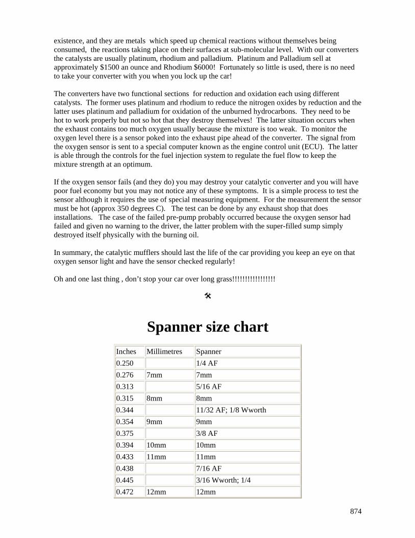
Spanner size chart Inches Millimetres Spanner 0.250 1/4 AF 0.276 7mm 7mm 0.313 5/16 AF 0.315 8mm 8mm 0.344 11/32 AF; 1/8 Wworth 0.354 9mm 9mm 0.375 3/8 AF 0.394 10mm 10mm 0.433 11mm 11mm 0.438 7/16 AF 0.445 3/16 Wworth; 1/4 0.472 12mm 12mm

875
0.500 1/2 AF 0.512 13mm 0.525 1/4 Wworth; 5/16 BSF 0.551 14mm 0.563 9/16 AF 0.591 15mm 0.600 5/16 Wworth; 3/8 BSF 0.625 5/8 AF 0.630 16mm 16mm 0.669 17mm 17mm 0.686 11/16 AF 0.709 18mm 18mm 0.710 3/8 Wworth; 7/16 BSF 0.748 19mm 19mm 0.750 3/4 AF 0.787 20mm 20mm 0.813 13/16 AF 0.820 7/16 Wworth; 1/2 BSF 0.826 21mm 21mm 0.866 22mm 22mm 0.875 7/8 AF 0.905 23mm 23mm 0.920 1/2 Wworth; 9/16 BSF 0.938 15/16 AF 0.945 24mm 24mm 0.984 25mm 25mm 1.000 1in AF 1.010 9/16 Wworth; 5/8 BSF 1.024 26mm 26mm 1.063 27mm 1 1/16 AF; 27mm 1.100 5/16 Wworth; 11/16 BSF 1.125 1 1/8 AF 1.181 30mm 30mm 1.200 11/16 Wworth; 3/4 BSF 1.250 1 1/4 AF 1.260 32mm 32mm 1.300 3/4 Wworth; 7/8 BSF 1.313 1 5/16 AF 1.390 13/16 Wworth; 15/16 BSF

876
1.417 36mm 36mm 1.418 1 7/16 AF 1.480 7/8 Wworth; 1in BSF 1.500 1 1/2 AF 1.575 40mm 15/16 AF; 40mm exactly 1.614 41mm 41mm 1.625 1 5/8 AF 1.670 1 in Wworth; 1 1/8 BSF 1.688 1 11/16 AF 1.811 46mm 46mm 1.813 1 13/16 AF 1.860 1 1/8 Wworth; 1 1/4 BSF 1.875 1 7/8 AF 1.969 50mm 50mm 2.000 2in AF 2.050 1 1/4 Wworth; 1 3/8 BSF 2.165 55mm 55mm 2.362 60mm 60mm