HYDRAULIC MOTORS - Ponar Wadowice1343,silniki_gerotorowe_2.pdf · DISC VALVE HYDRAULIC MOTORS Wheel...
56
HYDRAULIC MOTORS HYDRAULIC MOTORS
Transcript of HYDRAULIC MOTORS - Ponar Wadowice1343,silniki_gerotorowe_2.pdf · DISC VALVE HYDRAULIC MOTORS Wheel...

HYDRAULIC MOTORSHYDRAULIC MOTORS

DISC VALVE HYDRAULIC MOTORS
CONTENTS
Page
Hydraulic Motors Series MS .................................................................................... 4
Application Calculation ....................................................................................................... 54
•
•
•
•
•
•
Hydraulic Motors Series MT ................................................................................... 25
Hydraulic Motors Series MV .................................................................................. 39
Motor Special Features............................................................................................... 51
Motors with Speed Sensor................................................................................................... 52
“M+S HYDRAULIC” can accept no responsibility for possible errors in catalogues, brochures and other printed material.
“M+S HYDRAULIC” reserves the right to alter its products without notice. This also applies to products already on order provided that such
alterations can be made without subsequential changes being necessary in specifications already agreed.

The standard motor mounting flange is located as close to the output shaft as possible. This type of
mounting supports the motor close to the shaft load. This mounting flange is also compatible with many standard gear
boxes.
The wheel motor mounting flange is located near the center of the motor which permits part or all of
the motor to be located inside the wheel or roller hub. In traction drive applications, loads can be positioned over the motor
bearings for best bearing life. This wheel motor mounting flange provides design flexibility in many applications.
This motor is assembled without the output shaft, bearings and bearing housing and has the same
drive components as the standard motors. The short motor is especially suited for applications such as gear boxes, winch,
reel and roll drives. Short motor applications must be designed with a bearing supported internal spline to mate with the
short motor drive. Product designs using these hydraulic motors provide considerable cost savings.
LL Series hydraulic motors are designed to operate at the whole standard range of working
conditions (pressure drop and frequency of rotation ), but with considerable decreased volumetric losses in the drain
ports. This motors are suitable for hydraulic systems with series-conected motors with demands for low leakage.
LSV feature optimizes the motor for low-speed performance. Motors with this valving provide very
low low speed (up to
200 RPM)
speed while maintaining high torque. They are designed to run continuously at
at normal pressure drop and reduced flow. Optimal run is guaranteed at frequency of rotation from 20 to 50 RPM
. Motors with this valving have an increased starting pressure and are not recommended for using at pressure drop less
than 40 bar.
The high pressure shaft seals allow the motors to withstand high case pressures at high speeds
without external drain line.
DISTRIBUTOR VALVE
MS, MT, MV series motors have disk valve: the distributor valve has been separated from output shaft and is driven by short
cardan shaft. A balance plate counterbalances the hydraulic forces around the distributor valve. It gives the motors high
efficiency- even at high pressures, and good starting characteristics.
GEAR WHEELSET
There are two forms of gear wheel set: Gerotor set have plain teeth and Roll-gerotor set with teeth fitted with rollers.
MS, MT, MV series motors have roll-gerotor set. The rollers reduce local stress and the tangential reaction forces on the
rotor reducing friction to a minimum. This gives long operating life and better efficiency even at continuous high pressures.
DISC VALVE HYDRAULIC MOTORS
Wheel Motor
3
Short Motor
Orbit motors convert hydraulic energy (pressure, oil flow) into mechanical energy (torque, speed). Hydraulic orbit motors
operate on the principle of an internal gear (rotor) rotating within a fixed external gear (stator). The internal gear transmits
the torque generated by the application of pressure from hydraulic oil fed into motor which is then delivered via the motor's
output shaft. Orbit motors have high starting torque and constant output torque at wide speed range. The output shaft runs
on tapered roller bearings and can absorb high axial and radial forces.
GENERAL INFORMATION:
FEATURES:
Standard Motor
Low Speed
Valve
Low Leakage
Motors with
Speed Sensor
High Pressure
Shaft Seal
Motors are available with integrated inductive speed sensor. The output signal is a standardized
voltage signal that can be used to control the speed of a motor. The torque and the radial load of the
motor are not affected by the installation of speed sensor.

Specification data ............................................ 5÷6
Function diagrams ........................................ 7÷12
Dimensions and mounting ...........................13÷16
Tacho connection ............................................. 16
Shaft extensions .............................................. 17
Motor with Drum brake- MSB .......................... 18
Permissible Shaft Seal pressure........................17
Permissible shaft loads ................................... 19
Function diagram for MSB .............................. 19
Dimensions and mounting- MSS, V, U ...... 20÷23
Internal Spline data ......................................... 23
Order code ...................................................... 24
Pressure Losses
HYDRAULIC MOTORS MS
4
APPLICATION
CONTENTS OPTIONS
140 [2030]
210 3045[ ]
Pressure drop
[ ]bar PSI
Viscosity
[ ]mm /s SUS2
Oil flow in
drain line
[ ]lpm GPM
20 98
35 164
20 [98]
35 [164]
[ ]
[ ]
1,5 .396
1 .264
3 .793
2 .528
[ ]
[ ]
[ ]
[ ]
Oil flow in drain line
Max. Displacement,
Max. Speed,
Max. Torque,
Max. Output,
Max. Pressure Drop,
Max. Oil Flow,
Min. Speed,
Permissible Shaft Loads
Pressure fluid
Temperature range,
Optimal Viscosity range,
Filtration
cm /rev [in /rev]
[RPM]
daNm [lb-in]
kW [HP]
bar [PSI]
lpm [GPM]
[RPM]
daN [lbs]
C [ F]
mm /s [SUS]
3 3
O O
2
564,9 34.47
1 0
[7520] int.: 0
500 1125
-40÷140 [-40÷284]
20÷75 98÷347
[ ]
00
cont.: 85 99 [876 ]
23 [30.8]
cont.: 210 [3050] int.:
90 [24]
5
P = [ ]
Mineral based- HLP(DIN 51524) or HM(ISO 6743/4)
[ ]
ISO code 20/16 (Min. recommended fluid filtration of 25 micron)
275 [3990]
a
GENERAL
0
2
4
6
8
10
12
14
p
bar
00
100
150
200
50
p
PSI
90806050403020100
Q, GPM
70
2.5 5 7.5 10 12.5 15 17.5 20 22.5
Q, lpm
»
»
»
»
»
»
Conveyors
Metal working machines
Road building machines
Mining machinery
Food industries
» Agriculture machines
etc.Special vehicles
»
»
»
»
»
»
»
»
»
»
Model- Disc valve, roll-gerotor
Flange and wheel mount
Short motor
Motor with Drum Brake
Tacho connection
Speed sensoring
Side and rear ports
Shafts- straight, splined and tapered
SAE, Metric and BSPP ports
Other special features

MOTORS
MS
5
* Intermittent operation: the permissible values may occur for max. 10% of every minute.
** Peak load: the permissible values may occur for max. 1% of every minute.
*** For speeds lower than given, consult factory or your regional manager.
1. Intermittent speed and intermittent pressure must not occur simultaneously.
2. Recommended filtration is per ISO cleanliness code 20/16. A nominal f ltration of 25 micron or better.
3. Recommend using a premium quality, anti-wear type mineral based hydraulic oil HM ( ISO 6743/4).
If using synthetic fluids consult the factory for alternative seal materials.
4. Recommended minimum oil viscosity 13 mm²/s [70 SUS] at 50°C [122°F].
5. Recommended maximum system operating temperature is 82°C [180°F].
6. To assure optimum motor life fill with fluid prior to loading and run at moderate load and speed for 10-15 minutes.
i
HLP(DIN51524) or
MS 200
200 12.2
61 5400
72 6370
16,5 22.1
22 29.52
210 [3050]
275 [3990]
295 [4280]
75 [20]
90 [24]
230 [3340]
295 [4280]
300 [4350]
140 [2030]
175 [2540]
210 [3050]
8 115
47 4160
56 4960
11,2 24.7
11,7 25.8
9,2 20.2
7,1 15.6
11,6 25.6
18,2 41.1
[ ]
375
450
[ ]
[ ]
[ ]
[ ]
[ ]
[ ]
[ ]
6
[ ]
[ ]
[ ]
[ ]
[ ]
[ ]
SPECIFICATION DATA
Type MS 80 MS 100 MS 160MS 125
cont.
Int.*
cont.
Int.*
cont.
int.*
cont.
Int.*
peak**
cont.
Int.*
cont.
Int.*
peak**
cont.
Int.*
peak**
at max. press. drop cont.
at max. press. drop Int.*
MS(F)
MSW
MSS
MSV
MSQ
MSB
Displacement, [ ]
Max. Speed,
[RPM]
Max. Torque
[ ]
Max. Output
[ ]
Max. Pressure Drop
[ ]
Max. Oil Flow
[ ]
Max. Inlet Pressure
[ ]
Max. Return Pressure
with Drain Line
[ ]
Max. Starting Pressure with Unloaded Shaft, [ ]
Min. Starting Torque
[ ]
Min. Speed***, [RPM]
Weight, [ ]
cm.³/rev. in.³/rev.
daNm lb-in
kW HP
bar PSI
lpm GPM
bar PSI
bar PSI
bar PSI
daNm lb-in
kg lb
For Rear Ports
+ [ ]0,40 .88
80,5 4.91
24 2120
31 2740
15,5 20.8
19,5 26.2
210 [3050]
275 [3990]
295 [4280]
65 17
80 21
230 3340
295 4280
300 4350
140 2030
175 2540
210 3050
12 175
18 1590
23,5 2080
9,9 21.8
10,4 22.9
7,9 17.4
5,8 12.8
10,3 22.7
16,9 37.3
[ ]
810
1000
[ ]
[ ]
[ ]
[ ]
[ ]
[ ]
[ ]
[ ]
[ ]
[ ]
[ ]
[ ]
[ ]
[ ]
[ ]
10
[ ]
[ ]
[ ]
[ ]
[ ]
[ ]
100 6.1
30,5 2700
39 3450
18 24.1
22,8 30.2
210 [3050]
275 [3990]
295 [4280]
75 20
90 24
230 [3340]
295 [4280]
300 4350
140 2030
175 2540
210 3050
10 145
23 2040
30 2660
10,1 22.2
10,6 23.3
8,1 17.8
6 13.2
10,5 23.2
17,1 37.7
[ ]
750
900
[ ]
[ ]
[ ]
[ ]
[ ]
[ ]
[ ]
[ ]
[ ]
[ ]
[ ]
[ ]
[ ]
10
[ ]
[ ]
[ ]
[ ]
[ ]
[ ]
125,7 7.67
37,5 3320
49 4380
18 24.1
22,5 30.2
210 [3050]
275 [3990]
295 [4280]
75 [20]
90 [24]
230 [3340]
295 [4280]
300 [4350]
140 [2030]
175 [2540]
210 [3050]
10 145
29 2570
38 3360
10,4 22.9
10,9 24
8,4 18.5
6,3 13.9
10,8 23.8
17,4 38.3
[ ]
600
720
[ ]
[ ]
[ ]
[ ]
[ ]
[ ]
[ ]
8
[ ]
[ ]
[ ]
[ ]
[ ]
[ ]
159,7 9.74
49 4340
60 5310
16,5 22.1
23 30.8
210 [3050]
275 [3990]
295 [4280]
75 [20]
90 [24]
230 [3340]
295 [4280]
300 [4350]
140 [2030]
175 [2540]
210 [3050]
8 115
37 3270
46 4070
10,8 23.8
11,3 24.6
8,8 19.4
6,7 14.8
11,2 24.7
17,8 39.2
[ ]
470
560
[ ]
[ ]
[ ]
[ ]
[ ]
[ ]
[ ]
8
[ ]
[ ]
[ ]
[ ]
[ ]
[ ]
MOTORS
MS
6
MOTORS
MS
SPECIFICATION DATA (continued)
Type MS 250 MS 400 MS 475 MS 525MS 315
474,6 28.96
85 7520
99 8760
8,4 11
11,3 15
130 1880
150 2180
170 2470
71 [6280]
84 [7430
14,1 31
14,6 32.2
12.1 26.7
10 22
14,5 32
21,1 46.5
[ ]
160
190
[ ]
[ ]
[ ]
[ ]
[ ]
[ ]
[ ]
]
5
[ ]
[ ]
[ ]
[ ]
[ ]
[ ]
75 [20]
90 [24]
230 [3340]
295 [4280]
300 [4350]
140 [2030]
175 [2540]
210 [3050]
8 [115]
522,7 31.88
145
175
85 [7520]
99 [8760]
7,6 [10.2]
10,4 [13.9]
115 [1670]
135 [1960]
155 [2250]
71 [6280]
84 [7430
14,6 32.2
15,1 33.3
12,6 27.8
10,5 23.1
15 33.1
21,6 47.6
[ ]
]
5
[ ]
[ ]
[ ]
[ ]
[ ]
[ ]
75 [20]
90 [24]
230 [3340]
295 [4280]
300 [4350]
140 [2030]
175 [2540]
210 [3050]
8 [115]
cont.
Int.*
cont.
Int.*
cont.
int.*
cont.
Int.*
peak**
cont.
Int.*
cont.
Int.*
peak**
cont.
Int.*
peak**
at max. press. drop cont.
at max. press. drop Int.*
MS(F)
MSW
MSS
MSV
MSQ
MSB
MS 565
564,9 34.47
130
160
85 [7520]
99 [8760]
6,9 [9]
9,6 [13]
105 [1520]
125 [1810]
145 [2100]
71 [6280]
84 [7430
15 33.1
15,5 34.1
13 28.6
10,9 24
15,4 33.9
23 48.5
[ ]
]
5
[ ]
[ ]
[ ]
[ ]
[ ]
[ ]
75 [20]
90 [24]
230 [3340]
295 [4280]
300 [4350]
140 [2030]
175 [2540]
210 [3050]
8 [115]
250 15.3
1 ,5
2 0
0
11,7 25.8
12,2 26.9
9,7 21.4
7,6 16.7
12,1 26.7
18,7 41.2
[ ]
300
360
[ ]
[ ]
[ ]
[ ]
[ ]
[ ]
[ ]
6
[ ]
[ ]
[ ]
[ ]
[ ]
[ ]
72 6370
87 7700
4 19.4
18 24.1
200 [2900]
250 [3630]
7 3920
56 4960
7 6200
75 [20]
90 [24]
230 [3340]
295 [4280]
300 [4350]
140 [2030]
175 [2540]
210 [3050]
8 [115]
314,9 19.2
15
1
2 0
40
71 6280
85 7520
12,4 27.3
12,9 28.4
10,4 22.9
8,3 18.3
12,8 28.2
19,4 42.7
[ ]
240
290
[ ]
[ ]
[ ]
[ ]
[ ]
[ ]
[ ]
[ ]
[ ]
5
[ ]
[ ]
[ ]
[ ]
[ ]
[ ]
82,5 7300
100 8850
20.1
7 22.8
0 2900
2 3480
260 3770
75 [20]
90 [24]
230 [3340]
295 [4280]
300 [4350]
140 [2030]
175 [2540]
210 [3050]
8 [115]
397 24.2
9
1 1
1 1
1 0
1 0
0 0
71 6280
84 7430
13,1 29.3
13,8 30.4
11,3 24.9
9,2 20.2
13,7 30.2
20,3 44.7
[ ]
190
230
[ ]
[ ]
[ ]
[ ]
[ ]
[ ]
[ ]
[ ]
[ ]
5
[ ]
[ ]
[ ]
[ ]
[ ]
[ ]
86,5 7660
9 8760
1 4.8
2,5 6.8
6 2320
9 2760
21 305
75 [20]
90 [24]
230 [3340]
295 [4280]
300 [4350]
140 [2030]
175 [2540]
210 [3050]
8 [115]
Displacement, [ ]
Max. Speed,
[RPM]
Max. Torque
[ ]
Max. Output
[ ]
Max. Pressure Drop
[ ]
Max. Oil Flow
[ ]
Max. Inlet Pressure
[ ]
Max. Return Pressure
with Drain Line
[ ]
Max. Starting Pressure with Unloaded Shaft, [ ]
Min. Starting Torque
[ ]
Min. Speed***, [RPM]
Weight, [ ]
cm.³/rev. in.³/rev.
daNm lb-in
kW HP
bar PSI
lpm GPM
bar PSI
bar PSI
bar PSI
daNm lb-in
kg lb
For Rear Ports
+ [ ]0,40 .88
* Intermittent operation: the permissible values may occur for max. 10% of every minute.
** Peak load: the permissible values may occur for max. 1% of every minute.
*** For speeds lower than given, consult factory or your regional manager.
1. Intermittent speed and intermittent pressure must not occur simultaneously.
2. Recommended filtration is per ISO cleanliness code 20/16. A nominal f ltration of 25 micron or better.
3. Recommend using a premium quality, anti-wear type mineral based hydraulic oil HM ( ISO 6743/4).
If using synthetic fluids consult the factory for alternative seal materials.
4. Recommended minimum oil viscosity 13 mm²/s [70 SUS] at 50°C [122°F].
5. Recommended maximum system operating temperature is 82°C [180°F].
6. To assure optimum motor life fill with fluid prior to loading and run at moderate load and speed for 10-15 minutes.
i
HLP(DIN51524) or

FUNCTION DIAGRAMS
7
MOTORS
MS
MS 100
MS 80
M
daNm
20
l/m
in
5.3
GP
M
Q=
5l/m
in
1.3
GP
M
0
0 300100 400 500200
p=275 bar
3990 PSI
140 bar
2030 PSI
105 bar
1520 PSI
70 bar
1020 PSI
30 bar
440 PSI
n
5
co
nt.
int.
10
15
20
25
303
0l/m
in
7.9
GP
M
40
l/m
in
10
.6G
PM
50
l/m
in
13
.2G
PM
65
l/m
in
17
.2G
PM
10
l/m
in
2.6
GP
M
80
l/m
in
21
.1G
PM
1000900800700600
175 bar
2540 PSI
210 bar
3050 PSI
225 bar
3260 PSI
250 bar
3630 PSI
cont. int.
N=1 kW
t=8 %1
80%
78%
75%
60%
70%
12 kW15 kW
18 kW
9 kW
3 kW
6 kW
M
daNm
0
0 300100 400 500200
n
5
cont.
int.
10
15
20
25
30
75
l/m
in
19.8
GP
M
90
l/m
in
23.8
GP
M
950900800700600
cont. int.
N=1 kW
t=8 %3
80%
75%
60%
70%
12 kW
15 kW 18 kW
9 kW
3 kW
6 kW
35
40
45
12 hp 18 hp
15 hp9 hp6 hp
3 hp
1 hp
0
500
M
lb-in
1000
1500
2000
2500
3000
0
500
M
lb-in
1000
1500
2000
2500
3000
3500
4000
p=275 bar
3990 PSI
140 bar
2030 PSI
105 bar
1520 PSI
70 bar
1020 PSI
35 bar
510 PSI
175 bar
2540 PSI
210 bar
3050 PSI
225 bar
3260 PSI
250 bar
3630 PSI
20
l/m
in
5.3
GP
M
Q=
5l/m
in
1.3
GP
M
30
l/m
in
7.9
GP
M
40
l/m
in
10.6
GP
M
50
l/m
in
13.2
GP
M
10
l/m
in
2.6
GP
M
60
l/m
in
15.9
GP
M
3 hp
1 hp
6 hp
9 hp
12 hp
15 hp 18 hp
RPM
RPM
The function diagrams data is for average performance of randomly selected motors at back pressure
5÷10 bar [72.5÷145 PSI] and oil with viscosity of 32 mm²/s [150 SUS] at 50°C [122 F].o

FUNCTION DIAGRAMS
MS 160
8
MOTORS
MS
MS 125
20
l/m
in
5.3
GP
M
30
l/m
in
7.9
GP
M
40
l/m
in
10.6
GP
M
50
l/m
in
13.2
GP
M
60
l/m
in
15.9
GP
M
10
l/m
in
2.6
GP
M
90
l/m
in
23.8
GP
M
Q=
5l/m
in
1.3
GP
M
75
l/m
in
19.8
GP
M
M
daNm
0
0 300100 400 500200 RPM
n
5
cont.
int.
10
15
20
25
30
700600
cont. int.
N=1 kW
=85%
80%
t 83%
75%
60%
70%
12 kW 15 kW
9 kW
3 kW
6 kW
18 kW
21 kW
35
40
45
50
350150 450 550250 75065050
0
500
1000
1500
2000
2500
3000
3500
4500
M
lb-in
4000
p=275 bar
3990 PSI
140 bar
2030 PSI
105 bar
1520 PSI
70 bar
1020 PSI
35 bar
510 PSI
175 bar
2540 PSI
210 bar
3050 PSI
225 bar
3260 PSI
250 bar
3630 PSI
3 hp
1 hp
6 hp 9 hp12 hp
21 hp
18 hp
15 hp
20
l/m
in
5.3
GP
M
30
l/m
in
7.9
GP
M
40
l/m
in
10.6
GP
M
50
l/m
in
13.2
GP
M
60
l/m
in
15.9
GP
M
10
l/m
in
2.6
GP
M
90
l/m
in
23.8
GP
M
Q=
5l/m
in
1.3
GP
M
75
l/m
in
19.8
GP
M
M
daNm
0
0 300100 400 500200 RPM
n
5
cont.
int.
10
15
20
25
30
600
cont. int.
N=1 kW
=87%
80%
t
83%
75%60%
70%
12 kW 15 kW
9 kW
3 kW
6 kW
18 kW
21 kW
35
40
45
50
350150 450 55025050
0
1000
2000
3000
5000
M
lb-in
4000
p=260 bar
3770 PSI
140 bar
2030 PSI
105 bar
1520 PSI
70 bar
1020 PSI
35 bar
510 PSI
175 bar
2540 PSI
210 bar
3050 PSI
225 bar
3260 PSI
3 hp
1 hp
6 hp9 hp 12 hp
21 hp
18 hp
15 hp
55
60
6000
160 bar
2320 PSI
86% 85%
The function diagrams data is for average performance of randomly selected motors at back pressure
5÷10 bar [72.5÷145 PSI] and oil with viscosity of 32 mm²/s [150 SUS] at 50°C [122 F].o

FUNCTION DIAGRAMS
MS 200
MS 250
9
MOTORS
MS
20
l/m
in
5.3
GP
M
30
l/m
in
7.9
GP
M
40
l/m
in
10.6
GP
M
50
l/m
in
13.2
GP
M
60
l/m
in
15.9
GP
M
10
l/m
in
2.6
GP
M
90
l/m
in
23.8
GP
M
Q=
5l/m
in
1.3
GP
M
75
l/m
in
19.8
GP
M
M
daNm
0
0 300100 400 500200 RPM
n
5
cont.
int.
10
15
20
25
30
cont. int.
N=1 kW
=88%
80%
t
83%
75%
60%
70%
12 kW
15 kW
9 kW
3 kW
6 kW
18 kW
21 kW
35
40
45
50
350150 45025050
0
1000
2000
3000
M
lb-in
4000
140 bar
2030 PSI
105 bar
1520 PSI
70 bar
1020 PSI
30 bar
440 PSI
160 bar
2320 PSI
210 bar
3050 PSI
225 bar
3260 PSI
p=250 bar
3630 PSI
3 hp
1 hp
6 hp 9 hp
12 hp
21 hp
18 hp
15 hp
175 bar
2540 PSI
55
60
65
70
75
5000
6000
7000
86%
85%
20
l/m
in
5.3
GP
M
30
l/m
in
7.9
GP
M
40
l/m
in
10.6
GP
M
50
l/m
in
13.2
GP
M
60
l/m
in
15.9
GP
M
10
l/m
in
2.6
GP
M
90
l/m
in
23.8
GP
M
75
l/m
in
19.8
GP
M
M
daNm
0
0 300100 200 RPM
n
cont.
int.
10
20
30
cont. int.
N=1 kW =87%
80%
t83%
75%
60%
70%
12 kW
15 kW9 kW
3 kW
6 kW
18 kW
21 kW
40
50
350150 25050
0
1000
2000
3000
M
lb-in
4000
140 bar
2030 PSI
125 bar
1810 PSI
70 bar
1020 PSI
35 bar
510 PSI
155 bar
2250 PSI
200 bar
2900 PSI
225 bar
3260 PSI
p=250 bar
3630 PSI
3 hp
1 hp
6 hp 9 hp 12 hp
21 hp18 hp
15 hp
175 bar
2540 PSI60
70
5000
6000
7000
86%85%
95 bar
1390 PSI
80
90
Q=
5l/m
in
1.3
GP
M
8000
The function diagrams data is for average performance of randomly selected motors at back pressure
5÷10 bar [72.5÷145 PSI] and oil with viscosity of 32 mm²/s [150 SUS] at 50°C [122 F].o

MS 315
MS 400
10
MOTORS
MS
35 bar
510 PSI
FUNCTION DIAGRAMS
20
l/m
in
5.3
GP
M
30
l/m
in
7.9
GP
M
40
l/m
in
10.6
GP
M
50
l/m
in
13.2
GP
M
60
l/m
in
15.9
GP
M
10
l/m
in
2.6
GP
M
90
l/m
in
23.8
GP
M
Q=
5l/m
in
1.3
GP
M
75
l/m
in
19.8
GP
M
M
daNm
0
0 300100 200 RPM
n
cont.
int.
10
20
30
cont. int.
N=1 kW
=87%
80%
t
83%
75%
60%
70%
12 kW
15 kW
9 kW
3 kW
6 kW
18 kW
40
50
150 25050
0
1000
2000
3000
M
lb-in
4000
120 bar
1740 PSI
100 bar
1450 PSI
70 bar
1020 PSI
160 bar
2320 PSI
200 bar
2900 PSI
225 bar
3260 PSI
p=240 bar
3480 PSI
3 hp
1 hp
6 hp
9 hp
12 hp 18 hp15 hp
175 bar
2540 PSI
60
70
5000
6000
9000
85%
275125 175125 22525
80
90
100
7000
8000
140 bar
2030 PSI
20
l/m
in
5.3
GP
M
30
l/m
in
7.9
GP
M
40
l/m
in
10.6
GP
M
50
l/m
in
13.2
GP
M
60
l/m
in
15.9
GP
M
10
l/m
in
2.6
GP
M
90
l/m
in
23.8
GP
M
Q=
5l/m
in
1.3
GP
M
75
l/m
in
19.8
GP
M
M
daNm
0
0 100 200 RPM
n
cont.
int.
10
20
30
cont. int.
N=1 kW
=87%
80%
t
83%
75%
60%
70%
12 kW
15 kW
9 kW3 kW 6 kW
40
50
150 25050
0
1000
2000
3000
M
lb-in
4000
120 bar
1740 PSI
105 bar
1520 PSI
60 bar
870 PSI
160 bar
2320 PSI
p=190 bar
2760 PSI
3 hp
1 hp
6 hp
9 hp
12 hp 15 hp
175 bar
2540 PSI
60
70
5000
6000
9000
85%
125 175125 22525
80
90
100
7000
8000
140 bar
2030 PSI
30 bar
440 PSI
80 bar
1160 PSI
86%
The function diagrams data is for average performance of randomly selected motors at back pressure
5÷10 bar [72.5÷145 PSI] and oil with viscosity of 32 mm²/s [150 SUS] at 50°C [122 F].o

11
MOTORS
MS
MS 475
MS 525
FUNCTION DIAGRAMS
25 bar
360 PSI
25 bar
360 PSI
20
l/m
in
5.3
GP
M
30
l/m
in
7.9
GP
M
40
l/m
in
10.6
GP
M
50
l/m
in
13.2
GP
M
60
l/m
in
15.9
GP
M
10
l/m
in
2.6
GP
M
90
l/m
in
23.8
GP
M
Q=
5l/m
in
1.3
GP
M
75
l/m
in
19.8
GP
M
M
daNm
0
0 100 200 RPM
n
cont.
int.
10
20
30
cont. int.
N=1 kW
=88%
80%
t
83%
75%60%
70%
9 kW3 kW
6 kW
40
50
15050
0
1000
2000
3000
M
lb-in
4000
85 bar
1230 PSI
70 bar
1020 PSI
50 bar
730 PSI
120 bar
1740 PSI
p=150 bar
2180 PSI
3 hp
1 hp
6 hp
9 hp
12 hp
60
70
5000
6000
9000
85%
125 17512525
80
90
100
7000
8000
105 bar
1520 PSI
130 bar
1890 PSI
86%
12 kW
20
l/m
in
5.3
GP
M
30
l/m
in
7.9
GP
M
40
l/m
in
10.6
GP
M
50
l/m
in
13.2
GP
M
60
l/m
in
15.9
GP
M
10
l/m
in
2.6
GP
M
90
l/m
in
23.8
GP
M
Q=
5l/m
in
1.3
GP
M
75
l/m
in
19.8
GP
M
M
daNm
0
0 100 RPM
n
cont.
int.
10
20
30
cont. int.
N=1 kW
=88%
80%
t
83% 75%
60%
70%
9 kW
3 kW
6 kW
40
50
15050
0
1000
2000
3000
M
lb-in
4000
80 bar
1160 PSI
50 bar
730 PSI
105 bar
1520 PSI
p=135 bar
1960 PSI
3 hp
1 hp
6 hp9 hp
12 hp
60
70
5000
6000
9000
85%
125 17512525
80
90
100
7000
8000
90 bar
1300 PSI
115 bar
1670 PSI
86%
The function diagrams data is for average performance of randomly selected motors at back pressure
5÷10 bar [72.5÷145 PSI] and oil with viscosity of 32 mm²/s [150 SUS] at 50°C [122 F].o

12
MOTORS
MS
MS 565
FUNCTION DIAGRAMS
15 bar
220 PSI
20
l/m
in
5.3
GP
M
30
l/m
in
7.9
GP
M
40
l/m
in
10.6
GP
M
50
l/m
in
13.2
GP
M
60
l/m
in
15.9
GP
M
10
l/m
in
2.6
GP
M
90
l/m
in
23.8
GP
M
Q=
5l/m
in
1.3
GP
M
75
l/m
in
19.8
GP
M
M
daNm
0
0 100 RPM
n
cont.
int.
10
20
30
cont. int.
N=1 kW
=88%
80%
t
83%
75%
60%70%
9 kW
3 kW6 kW
40
50
12040
0
1000
2000
3000
M
lb-in
4000
70 bar
1020 PSI
45 bar
650 PSI
105 bar
1520 PSI
p=125 bar
1810 PSI
3 hp
1 hp
6 hp
9 hp
12 hp
60
70
5000
6000
9000
85%
16020
80
90
100
7000
8000
85 bar
1230 PSI
86%
60 80 140
60 bar
870 PSI
30 bar
430 PSI
The function diagrams data is for average performance of randomly selected motors at back pressure
5÷10 bar [72.5÷145 PSI] and oil with viscosity of 32 mm²/s [150 SUS] at 50°C [122 F].o

DIMENSIONS AND MOUNTING DATA
MS, MSF, MSA, MSW
13
MOTORS
MS
* -For Rear Ported Motors.
Type
MS(F, A) 80
100
125
160
200
250
315
400
475
MS(F, A)
MS(F, A)
MS(F, A)
MS(F, A)
MS(F, A)
MS(F, A)
MS(F, A)
MS(F, A)
MS(F, A) 525
MS(F, A) 565
*L ,
173
177
181
187
194
203
214
228
242
234
240
E mm[in.]
[6.81]
[6.97]
[7.13]
[7.36]
[7.64]
[7.99]
[8.43]
[8.98]
[9.53]
[9.21]
[9.45]
P(A,B)
Port A
Port B
C
T
SL Shaft
K ShaftSH Shaft
C Shaft
CO Shaft
K ShaftSH Shaft
C Shaft
CO Shaft
Shaft Dim.See Page 17
Flange Dim.See Page 15
Port Dim.See Page 16
Type
MSW 80
MSW100
MSW 125
MSW 160
MSW 200
MSW 250
MSW 315
MSW 400
MSW 475
MSW 525
MSW 565
L, mm[in.]
129 [5.08]
133 [5.23]
137 [5.39]
143 [5.63 ]
150 [5.91]
159 [6.26]
170 [6.69]
184 [7.24]
198 [7.79]
190 [7.48]
196 [7.72]
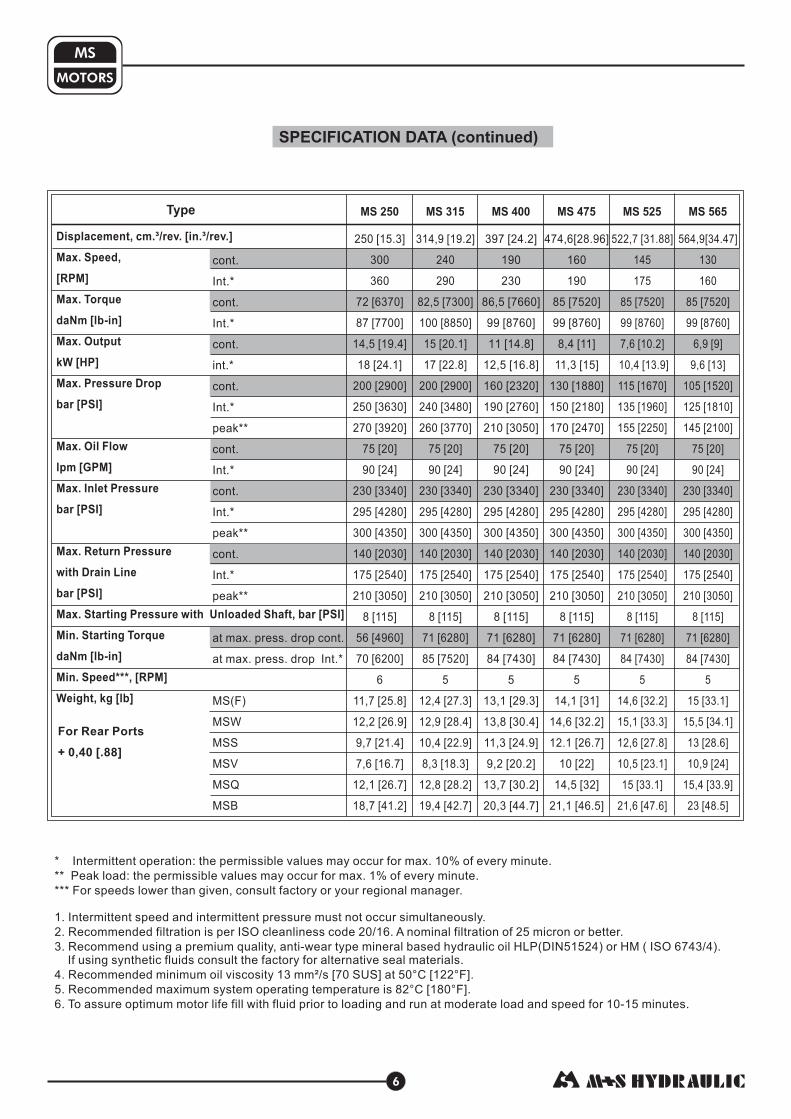
Standard Rotation
A CW
B CCW
Viewed from Shaft EndPort Pressurized -Port Pressurized -
Reverse Rotation
A CCW
B CW
Viewed from Shaft EndPort Pressurized -Port Pressurized -
L,
[ ]
[ ]
[ ]
[ ]
[ ]
[ ]
[ ]
[ ]
[ ]
[ ]
mm[in.]
168 6.61
171 6.73
176 6.93
182 7.17
189 7.44
197 7.76
209 8.23
223 8.78
237 9.33
229 [9.02]
235 9.25
L , [ ]
[ ]
[ ]
[ ]
[ ]
[ ]
[ ]
[ ]
[ ]
[ ]
[ ]
2 mm in.
124 4.88
128 5.04
132 5.20
138 5.43
145 5.71
154 6.06
165 6.50
179 7.05
193 7.60
185 [7.28]
191 7.52
L ,
[ ]
[ ]
[ ]
[ ]
[ ]
[ ]
[ ]
[ ]
[ ]
[ ]
1 mm[in.]
14,0 .55
17,4 .69
21,8 .86
27,8 1.09
34,8 1.37
43,5 1.71
54,8 2.16
69,4 2.73
82,6 3.25
74,5 [2.93]
80,2 3.16
L ,in.[mm]
[ ]
[ ]
[ ]
[ ]
[ ]
[ ]
[ ]
[ ]
[ ]
[ ]
[ ]
2
87 3.43
91 3.58
95 3.74
101 3.98
108 4.25
117 4.61
128 5.04
143 5.63
156 6.14
148 5.83
154 6.06
*L ,mm[in.]
138 [5.43]
142 [5.59]
146 [5.75]
152 [5.99]
159 [6.26]
168 [6.62]
179 [7.05]
194 [7.64]
207 [8.15]
199 [7.84]
205 [8.07]
E
11
0[4
.33
]
67
,85
[2.6
71
]
67
,85
[2.6
71
]
65
[2.5
35
]
57
,85
[2.2
77
]
14
6[5
.74
8]
10
4[4
.09
]
ma
xL
Port A Port B
ma
xL
10
4[4
.09
]
94
[3.7
01
]
28
[1.1
02
]
mm [in]
C
P
T
: 2xM10-12 mm depth: 2xG1/2 or 2xM22x1,5-15 mm depth
: G ¼ or M14x1,5- 12 mm depth (plugged)
[.47 in][.59 in]
[.47 in](A,B)
max 103
[4.055]
max 103[4.055]
42
[1.6
5]
78
[3.0
7]
SA Shaft SA Shaft
E Rear ports
SL Shaft
ma
xL
E
L1
L2
L1 L2

14
* -For Rear Ported Motors.
Type
MSQ 80
MSQ 100
MSQ 125
MSQ 160
MSQ 200
MSQ 250
MSQ 315
MSQ 400
MSQ 475
MSQ 525
MSQ 565
L,
179
183
187
193
200
209
220
235
247
240
246
mm [in.]
[7.05]
[7.21]
[7.36]
[7.60]
[7.87]
[8.23]
[8.66]
[9.25]
[9.72]
[9.45]
[9.69]
L ,
136
140
144
150
157
166
177
192
205
197
2 mm [in.]
[5.35]
[5.51]
[5.67]
[5.91]
[6.18]
[6.54]
[6.67]
[7.56]
[8.07]
[7.76]
203 [7.99]
*L ,
185
189
193
199
206
215
226
241
254
246
252
E mm [in.]
[7.28]
[7.44]
[7.60]
[7.83]
[8.11]
[8.46]
[8.90]
[9.49]
[10.0]
[9.69]
[9.92]
L ,
.55 [14,0]
.69 [17,4]
.86 [21,8]
1.09 [27,8]
1.37 [34,8]
1.71 [43,5]
2.16 [54,8]
2.73 [69,4]
3.25 [82,6]
3.16 [80,2]
1 mm [in.]
2.93 [74,5]
DIMENSIONS AND MOUNTING DATA - MSQ
MOTORS
MS
Shaft Dim.See Page 17
Standard Rotation
A CW
B CCW
Viewed from Shaft EndPort Pressurized -Port Pressurized -
Reverse Rotation
A CCW
B CW
Viewed from Shaft EndPort Pressurized -Port Pressurized -
ma
xL
E
Port BPort A
Port Dim.See Page 16
C
P
T
: 2xM10-12 mm depth: 2xG1/2 or 2xM22x1,5-15 mm depth
: G ¼ or M14x1,5- 12 mm depth (plugged)
[.47 in][.59 in]
[.47 in](A,B)
mm [in]
P(A,B)
C
T
SL Shaft
K ShaftSH Shaft
C ShaftCO Shaft
Port A
Port B
54
,35
[2.1
4]
ma
xL
54
,35
[2.1
4]
44
,35
[1.7
46
]
77
[3.0
31
]
96
,5[3
.79
9]
max 103
[4.055]
28
.5[1
.12
]
SA Shaft
L1
L2
L2
E Rear ports

15
MOTORS
MS
SAE A-4 Mount (4 Holes)
A SAE A-2 Mount (2 Holes)
F Magneto Mount (4 Holes)
Q Square Mount (4 Holes)
W Wheel Mount
ø8
2,5
+0
,05
+.0
01
9[3
.24
8]
ma
x1
31
[5.1
57
]
max
126
[4.9
6]
max
105
[4.1
33]
[.531]
4xø13,5
ø106,4±0,2
[4.189±.0078] [.24±.0098]
6,1±0,25
18
[.709]
53
[2.086]
ø8
2,5
+0
,05
+.0
01
9[3
.24
8]
[.24±.0098]
6,1±0,25ø106,4±0,2
[4.189±.0078]
max 103
[4.055]
4xø11,5
[.453]
18
[.709]
ø95[3.74]
[.24±.0098]
6,1±0,25
ø8
2,5
+0
,05
+.0
01
9[3
.24
8]
[.709]
18
ø1
25
-0,0
63
-.0
02
5[4
.92
1]
[.531]
4xø13,5
16
[.629]
max 139
[5.47]
9
[.354]
43
[1.693]
ø160±0,2
[6.299±.0078]
mm [in]
ma
x1
39
[5.4
7]
ma
x1
03
[4.0
55
]
MOUNTING
ø8
2,5
+0
,05
+.0
01
9[3
.24
8]
ma
x1
31
[5.1
57
]
[.531]
2xø13,5
ø106,4±0,2
[4.189±.0078] [.24±.0098]
6,1±0,25
18
[.709]
53
[2.086]
ma
x1
36
[5.3
5]
ø106,4±0,2
[4.189±.0078][.531]
4xø13,5
ø95[3.74]
22,5 0 22,50
max
126
[4.9
6]
ma
xø
73
[2.8
7]
Standard Rotation
A CW
B CCW
Viewed from Shaft EndPort Pressurized -Port Pressurized -
Reverse Rotation
A CCW
B CW
Viewed from Shaft EndPort Pressurized -Port Pressurized -
16
MOTORS
MS
E Rear PortsSide Ports
MOTORS WITH TACHO CONNECTION
P(A,B)
Port A
Port B53
[2.086]
32
±0
,3
[1.2
6±
.011
8]
32
±0
,3
[1.2
6±
.011
8]
P(A,B)
C1
6±
0,3
22±0,3
[.6
3]
±.0
11
8
16
±0
,3
[.6
3]
±.0
11
8
21
±0
,3
[.8
27
]±
.011
8
21
±0
,3
[.8
27
]±
.011
8
[.866±.0118]
5±0,15
[.197±.0059]
5±0,15
[.197±.0059]
max L
L2
Port B
Port A
2016
[.63] [.787]
5
[.197]
ø3[.118]
33[1.299]
ø34
[1.339]
4xM5
8 [.315] depth
53
[2.086]
max L
ø4
8
ø8
[1.8
9]
[.3
15
]
C
P
T
: 2xM10-12 mm depth: 2xG1/2 or 2xM22x1,5-15 mm depth
: G ¼ or M14x1,5- 12 mm depth (plugged)
[.47 in][.59 in]
[.47 in](A,B)
53
[2.086]
mm [in]
PORTS

SHAFT EXTENSIONS
- ø32 straight, Parallel key A10x8x45 DIN 6885Max. Torque 77 daNm [6815 lb-in]
- tapered 1:10, Parallel key B6x6x20 DIN 6885Max. Torque 95 daNm [8400 lb-in]
- p.t.o. DIN 9611 Form 1Max. Torque 77 daNmø34,85
[6815 lb-in]
- ø plined 14T, DP12/24 ANS B92.1-197Max. Torque 95 daNm
1¼" s 0[8400 lb-in]
SH
SL
KC
CO - ø1¼" straight, Parallel key "x "x 1¼"BS46Max. Torque 77 daNm [6815 lb-in]
516
516
17
MOTORS
MS
56,5±0,4
[2.224±.016]
10 -0,036
ø3
5
[1.3
78
]
ø3
235
-0,2
[1.3
78
]-.
00
79
[.394 ]-.0014
M8
min 16 deep[.63]
+.0
00
1
+0
,00
2+
0,0
18
[1.2
6]
+.0
00
7
S=41Tightening torque
20±1 daNm[1770±88.5 lb-in]
58±0,45
ø4,5
ø3
5-0
,03
9
19
,1-0
,1
6 -0,03
[.236 ]-.0011
-.0
03
9[.
75
1]
-.0
01
5[1
.37
8]
36
Taper :101[.196]
[.177]
[2.283 .016]±
ø4
4
[1.7
32
]
M2
0x1
,5
A-A A
A
ø3
5
[1.3
78
]
M8
min 16 deep[.63] 56,5±0,4
[2.224±.016]
ø3
1,7
5 -.0
01
-0,0
25
[1.2
5]
36+2
[1.417 ]+.079
ø3
5
[1.3
78
]
ø3
1,7
5 -.0
02
-0,0
51
[1.2
5]
35
,33
-0,2
5
[1.3
9]
-.0
01
7,96-0,025
[.313 ]-.001
3/8-16UNC
min 1 deep9 [.75]47,5±0,4
[1.87±.016]
8,64 -0,11
[.34 ]-.0043
A-A
ø28,9 -0,15
[1.138 ]-.006
ø3
5
[1.3
78
]
ø3
4,8
5 -.0
04
7
-0,1
2
[1.3
72
]
100±0,4
[3.937±.016]
A
A
7
[.28]
76 1±
[2.992±.039]38±0,25
[1.496±.01]
30
0
ø2
9,4
±0
,1
[1.1
57
±.0
03
9]
R6,7
[.264]
Max. return pressure without drain line ormax. pressure in the drain line
MAX. PERMISSIBLE SHAFT SEAL PRESSURE
- continuous operations
- intermittent operations
mm [in]
SA - T DP1 / ANS B92.1-197Max. Torque daNm
7/8''-13 splined 6 32 020 [1770 lb-in]
ø3
5
[1.3
78
]
33 2±0,[.512±.0197]
ø2
2±
0,1
[.8
66
±.0
03
9]
13 5±0,
[1.299 .0079]±
R4
[ 16].R2,5
.098
ø18,6 -0,2
-.0079[.732 ]
[1.417]

DIMENSIONS AND MOUNTING DATA
18
MOTORS
MS
A B
Releasing the level, the springs pull it and the brake pads backto the initial position. The motor output shaft is released.Minimum angle adjustment is 10 . It can be adjusted bydismounting the level. Depending on the application You canchoose the actuating direction of the brake level. The rodconnection actuating the brake should be capable of movingat last 25 mm from neutral to extreme position.
0
Actuating the brake level, the brakeshaft is turned. The rectangular shapeof the inner part of this shaft forces thebrake pads to be pressed against thebrake drum. This brakes the wheel orthe winch drum.
* -For Rear Ported Motors.
Port Dim.See Page 16
MSB Motor with Drum Brake
Type
MSB 80
MSB100
MSB 125
MSB 160
MSB 200
MSB 250
MSB 315
MSB 400
MSB 475
MSB 525
MSB 565
*L , mm[in]E
127 [5.00]
130 [5.12]
134 [5.28]
140 [5.51]
147 [5.79]
156 [6.14]
167 [6.57]
182 [7.17]
196 [7.72]
188 [7.40]
192 [7.56]
L, mm[in]
119 [4.69]
122 [4.80]
126 [4.96]
132 [5.20]
139 [5.47]
148 [5.83]
159 [6.26]
174 [6.85]
188 [7.40]
180 [7.09]
186 [7.32]Standard Rotation
A CW
B CCW
Viewed from Shaft EndPort Pressurized -Port Pressurized -
Reverse Rotation
A CCW
B CW
Viewed from Shaft EndPort Pressurized -Port Pressurized -
L ,
[ ]
[ ]
[ ]
[ ]
[ ]
[ ]
[ ]
[ ]
[ ]
[ ]
1 mm[in.]
14,0 .55
17,4 .69
21,8 .86
27,8 1.09
34,8 1.37
43,5 1.71
54,8 2.16
69,4 2.73
82,6 3.25
74,5 [2.93]
80,2 3.16
L ,2 mm[in.]
74 [2.91]
77 [3.03]
82 [3.23]
88 [3.47]
95 [3.74]
110 [4.33]
115 [4.53]
130 [5.12]
143 [5.63]
135 [5.32]
141 [5.55]
MSBR
MSBL
MD
PL
PL
70
53
[2.165]
[2.7
56
]7
0[2
.75
6]
ø155±0,5
[6.102±.0196]90
[3.54]max 122,5
[4.82]ø139,7±0,3
[5.5±.0118]
ma
x1
0,5
2
[4.7
5]
FS=5
68
,3
[2.6
9]
17
[.6
7]
4xM12
[2.13]
max 54
ø10,3
[.406]
10
[.3
9]
4,3
[.1
69
]
4±
0,2
[15
7±
.00
78
]
ø130-0,075
-.0029[5.118 ]
ma
xL
E
Port A Port B
P(A,B)
C
T
10
[.3
9]
26
[1.0
2]
16
[.6
3]
ma
x4
7[1
.85
]
17
,5
[.6
9]
ma
xL
Port A
Port B
5xM12x1,5
max ø199,5
[7.85]
ø101,6 -0,2
-.0078[4.0 ]
103
[4.055]
C
P
T
: 2xM10-12 mm depth
: 2xG1/2 or 2xM22x1,5-15 mm depth
: G ¼ or M14x1,5- 12 mm depth (plugged)
[.47 in]: Inspection hole for checking brake lining
[.59 in]
[.47 in]
F
(A,B)
mm [in]
E Rear ports
L1
L2
L1
19
MOTORS
MS
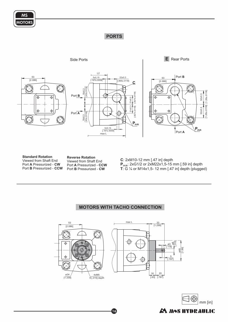
FUNCTION DIAGRAM MSB
PERMISSIBLE SHAFT LOADS
P - Brake Lever LoadM - Brake TorqueM - Brake Lever Torque
L
B
D
Mounting Flange:
Shaft: All type shafts except SA
StandardA-2Magneto
W - Wheel
Q - Square
500 daN1124 lbs.
Curve " " shows max. radial shaft load. Any shaft load exceeding the values quoted in the curve will seriouslyreduce motor life.
1
The output shaft runs in tapered bearings that permit high axial and radial forces. The permissible radial loadon the shaft is shown for an axial load of 0 N as function of the distance from the mounting flange to the point ofload application. The curves apply to a B10 bearing life of 2000 hours at 100 RPM .
mm
Prlbs
1000
2000
3000
PrdaN
01200 20 40 60 80 100
in3.50 1 1.5 2 2.5 3.5 4 4.5
11500
2500
5001000
2000
3000
0
4000
5000
6000
7000
11010 30 50 70 90
mm0 20 40 60 8010 30 50 70-10-20-30
in0 1 1.5 2 2.5 3.5-.5-1
mm0 20 40 6010 30 50 70-10-20
in0 1 1.5 2 2.5.5-.5-1
daNm20 40 50 60 7030100
2000 4000 5000 6000300010000 lb-in
daNmlb-in
MB
MD
10
8
6
4
2
12
14
948
790
632
474
316
1106
1264
158
120
0
20
40
60
80
100
110
10
30
50
70
90
150
130
140
daN lbs
PL
0
20
40
60
80
100
120
140
160
180
200
220
240
260
280
300
320
340
-2
-30-40

20
MOTORS
MS
DIMENSIONS AND MOUNTING DATA - MSS and MSV
Type
MSV 80
MSV 100
MSV 125
MSV 160
MSV 200
MSV 250
MSV 315
MSV 400
MSV 475
MSV 525
MSV 565
Type
MSS 80
100
125
160
200
250
315
400
475
MSS 525
MSS 565
MSS
MSS
MSS
MSS
MSS
MSS
MSS
MSS
* -For Rear Ported Motors.
V Very Short MountS Short Mount
T
P(A,B)
C
C
P
T
: 2xM10-12 mm depth: 2xG1/2 or 2xM22x1,5-15 mm depth
: G ¼ or M14x1,5- 12 mm depth (plugged)
[.47 in][.59 in]
[.47 in](A,B)
Port Dim.See Page 16
Standard Rotation
A CW
B CCW
Viewed from Shaft EndPort Pressurized -Port Pressurized -
Reverse Rotation
A CCW
B CW
Viewed from Shaft EndPort Pressurized -Port Pressurized -
ma
xL
ma
xL
E
Port BPort A
Port A
Port B Port B
Port A
ma
xL
L2
L2
L1L1
P(A,B)
C
L,
[ ]
[ ]
[ ]
[ ]
[ ]
[ ]
[ ]
[ ]
[ ]
[ ]
[ ]
mm[in]
125 4.92
129 5.08
133 5.24
139 5.47
146 5.75
155 6.10
166 6.54
181 7.13
194 7.64
186 7.32
192 7.56
L , ]
[ ]
[ ]
[ ]
[ ]
[ ]
[ ]
[ ]
[ ]
[ ]
[ ]
[ ]
2 mm[in]
83 3.27
87 3.43
90 3.54
96 3.78
103 4.05
112 4.41
123 4.84
138 5.43
152 5.98
144 5.67
150 5.91
L,
[ ]
[ ]
[ ]
[ ]
[ ]
[ ]
[ ]
[ ]
[ ]
[ ]
[ ]
mm[in]
91 3.58
94 3.70
99 3.90
105 4.13
112 4.41
120 4.72
132 5.20
146 5.75
160 6.30
152 5.98
158 6.22
L ,
[ ]
[ ]
[ ]
[ ]
[ ]
[ ]
[ ]
[ ]
[ ]
[ ]
[ ]
2 mm[in]
47 1.85
50,5 1.99
55 2.17
61 2.40
68 2.78
76,5 3.01
88 3.46
103 4.05
116 4.57
108 4.25
114 4.49
L ,mm[in]
14,0 [.55]
17,4 [.69]
21,8 [.86]
27,8 [1.09]
34,8 [1.37]
43,5 [1.71]
54,8 [2.16]
69,4 [2.73]
82,6 [3.25]
74,5 [2.93]
80,2 [3.16]
1* mm[in]EL ,
[ ]
[ ]
[ ]
[ ]
[ ]
[ ]
[ ]
[ ]
[ ]
[ ]
[ ]
134 5.28
138 5.43
141 5.55
147 5.79
154 6.06
163 6.42
174 6.85
189 7.44
203 7.99
195 7.68
201 7.91
* mm[in]
97 3.82
100 3.94
105 4.13
111 4.37
118 4.64
126 4.96
138 5.43
153 6.02
166 6.54
158 6.22
164 6.46
EL ,
[ ]
[ ]
[ ]
[ ]
[ ]
[ ]
[ ]
[ ]
[ ]
[ ]
[ ]
ø100 -0,054
-.0021[3.937 ]
6±
0,2
[.2
36
±.0
07
8]
"O" Ring 100x3
23
[.9
05
]
min
23
,8[.
93
7]
ma
x2
7,1
[1.0
67
]
max 103
[4.055]
24
[.945]
ø104±0,15
[4.095±.0059] ø5 [.197]
Drain port
102
[4.016]
37
[1.4
57
]
53
[2.1
65
]
ma
x2
5[.
98
4]
"O" Ring 85x2
ø90 -0,04
-.0047[3.543 ]
16
[.6
3] m
in4
5[1
.77
2]
ma
x4
5,6
[1.7
95
]
4xM10
-0,12
-.0016
16
±0
,1
[.6
3±
.00
39
]
mm [in]
ø125±0,15
[4.921±.0059]
ø145
[5.708]
30
[1.1
8]
37
[1.4
57
]
24
[.945]
ø4
[.157]
ø5
[.197]
4xø11
[.433]
E Rear ports

21
MOTORS
MS
DIMENSIONS AND MOUNTING DATA - MSU
* -For Rear Ported Motors.
U Ultra Short Mount
P(A,B)
C
C
P
: 2xM10-12 mm [.47 in] depth: 2xG1/2 or 2xM22x1,5
15 mm [.59 in] depth(A,B)
Standard Rotation
A CW
B CCW
Viewed from Shaft EndPort Pressurized -Port Pressurized -
Reverse Rotation
A CCW
B CW
Viewed from Shaft EndPort Pressurized -Port Pressurized -
Type
MSU 80
MSU 100
MSU 125
MSU 160
MSU 200
MSU 250
MSU 315
MSU 400
MSU 475
MSU 525
MSU 565
L,
[ ]
[ ]
[ ]
[ ]
[ ]
[ ]
[ ]
[ ]
[ ]
[ ]
[ ]
mm[in]
105,5 4.15
109 4.29
113 4.45
119 4.69
126 4.96
135 5.32
146 5.75
160 6.30
174 6.85
166 6.54
172 6.77
L ,
[ ]
[ ]
[ ]
[ ]
[ ]
[ ]
[ ]
[ ]
[ ]
[ ]
[ ]
2 mm[in]
63 2.48
66,5 2.62
71 2.80
77 3.03
84 3.31
92,5 3.64
104 4.09
119 4.69
132 5.20
124 4.88
130 5.12
*L ,
[ ]
[ ]
[ ]
[ ]
[ ]
[ ]
[ ]
[ ]
[ ]
[ ]
[ ]
E mm[in]
111,5 4.39
115 4.53
119 4.69
125 4.92
132 5.20
141 5.55
152 5.98
167 6.58
180 7.09
172 6.77
178 7.01
L1,mm[in]
14,0 [.55]
17,4 [.69]
21,8 [.86]
27,8 [1.09]
34,8 [1.37]
43,5 [1.71]
54,8 [2.16]
69,4 [2.73]
82,6 [3.25]
74,5 [2.93]
80,2 [3.16]
ma
xL
Port B
Port A
ø104±0,15
[4.095±.0059]ø5 [.197]
Drain port
102
53
[2.1
65
]25
,7
[1.0
12
]
Port BPort A
ma
x2
3
[.2
76
]
7
[.2
76
]
"O" Ring 75x3
ø75-0,04
-.0047[2.953 ]
-0,12
-.0016
4xM10
45
+1
,1
-.0
03
5[1
.77
2]
-0,9
+.0
04
3
Port Dim.See Page 16
[4.016]
mm [in]
E Rear ports
ma
xL
E
L2 L1

DIMENSIONS OF THE ATTACHED COMPONENT
For MSS
: Oil circulation hole: Hardened stop plate
F
H
J: 4xM10-16 mm [.63 in] depth, 900
G
K
: Internal drain channel
: Conical seal ringI : O- Ring 100x3 mm [3.94x.12 in]
T: Drain connection G1/4 or M14x1,5
22
MOTORS
MS
For MSV
: O- Ring 85x2 mm [3.346x.0787 in]: seal ring
G: Internal drain channel
ConicalI
K
F
J
H
: Oil circulation holeF
H: Hardened stop plateJ: 4xM10-26 mm [1.024 in] depth, 90
0
I T
K
G
I
G
K
HF
ø2
9±
0,5
[1.1
42
±.0
19
7]
52±0,3
[2.047±.0118]
27+0,5
+.0078[1.063 ]
+0,2
+.019
8+0,4
[.315 ]+.0157
ø3
5±
0,5
[1.3
78
±.0
19
7]
min
ø4
0[1
.57
5]
min
ø4
[.1
58
]
ø1
07
±0
,7
[4.2
12
±.0
27
5]
ø1
25
±0
,15
[4.9
21
±.0
05
9
ø1
00
[3.9
37
]
+0
,08
7
+.0
03
4
ø4
0[1
.57
5]
External Spline12 DP 12/24
ANS B92.1-76
2,3±0,05
[.091±.0019]
20±1
[.787±.039]
External Spline12 DP 12/24
ANS B92.1-76
min
ø4
[.1
58
]
ø2
9±
0,5
[1.1
42
±.0
19
7]
ø3
5±
0,5
[1.3
78
±.0
19
7]
min
ø4
0[1
.57
5]
ø1
04
±0
,15
[4.0
94
±.0
05
9]
ø9
0
[3.5
43
]
+0
,05
+.0
01
9
ma
xø
52
[2.0
5]
26±0,1
[1.023±.0039]
46±0,4
[1.811±.0157]
1.8±0,2
[.071±.0078]
15+0,5
+.0157[.591 ]
J
20
0
1,5±0,4
[.059±.0157]
mm [in]

DIMENSIONS OF THE ATTACHED COMPONENT(continued)
For MSU
23
MOTORS
MS
DRAIN CONNECTION
A drain line ought to be used when pressure in the return line can exceed the permissible pressure. It can be
connected:
- For MSS at the drain port of the motor;
- For MSV and MSU at the drain connection of the attached component.
The drain line must be possible for oil to flow freely between motor and attached component and must be led to the
tank. The maximum pressure in the drain line is limited by the attached component and its seal.
The maximum pressure in the drain line is
limited by the attached component and its shaft seal.
J
I
: 4xM10-26 mm [1.024 in] depth, 90 , ø104 [4.094]: O- Ring 75x3 mm [2.952x.12 in]
0
Standard ANS B92.1-1976, class 5[ x.m=+0,8]m=2.1166; corrected
INTERNAL SPLINE DATA FOR THE ATTACHED COMPONENT
J
: Internal drain channelG
K: Conical seal ring
IExternal Spline
12 DP 12/24ANS B92.1-76
G
K
min
ø4
0[1
.57
5]
[1.3
78
±.0
19
7]
ø3
5±
0,5
[1.1
42
±.0
19
7]
ø2
9±
0,5
2,3±0,05
[.091±.0019]
0,5±0,4
[.019±.0157]
46,2+0,3
+.0118[1.819 ]
7,5 +0,5
+.0197[.295 ]
min 15
[.59]
0,006
0,13
ø7
5
[2.9
53
]
+0
,09
+.0
03
5
+0
,02
+.0
00
8
ø8
2,8
[3.2
6]
+0
,2
+.0
07
8
0,25
19±0,1
[.748±.0039]
mm
12
12/24
30º
25,4
28,0
23,0
4,308±0,020
0,2
17,62
4,835±0,001
-0,1
+0,033
+0,15
inch
12
12/24
30º
1
1.1 ÷ 1.098
.907 ÷ .905
.1704 ÷ .1688
.008
.699 ÷ .694
.19039÷.19031
z
DP
D
Dri
Di
Lo
R
L
d
Fillet Root Side Fit
Number of Teeth
Diametral Pitch
Pressure Angle
Pitch Dia.
Major Dia.
Minor Dia.
Space Width [Circular]
Fillet Radius
Max. Measurement
between Pins
Pin Dia.
Hardening Specification:HV=750±50 on the surfaceHV=560 at 0,7±0,2 mm [.035÷.019 in] case depthMaterial: 20 MoCr4 EN 10084 or better
mm [in]

24
MOTORS
MS
ORDER CODE
omit - Side ports
- Rear portsE
- ø32 straight, Parallel key A10x8x45 DIN6885
- ø1¼" straight, Parallel key / ”x / ”x1¼” BS46
-
- ø34,85 p.t.o. DIN 9611 Form 1
- ø1¼" splined 14T ANS B92.1-1970
- 7/8"-13T splined ANS B92.1-1970
C
CO
K
SL
SH
SA
5 5
16 16
ø35 tapered 1:10, Parallel key B6x6x20 DIN6885
M S
Pos.1 - Mounting Flange
Pos.2- Port type
Pos.3 - Displacement code
1 2 3 4 5 6 7 8
Pos.4 - *Shaft Extensions
NOTES:
* The permissible output torque for shafts must not be exceeded!** Only for MSB
omit - SAE A-4 mount, four holes
- SAE A-2 mount, two holes
- Magneto mount, four holes
- Square mount, four holes
- Motor with drum brake
- Short mount
- mount
- mount
-
A
F
Q
B
S
V
U
W
Very short
Ultra short
Wheel mount
omit - BSPP (ISO 228)
- Metric (ISO 262)M
Pos. 5 - Ports
The hydraulic motors are mangano-phosphatized as standard.
Pos. 6 - **Actuating Direction
- Right
- Left
/R
/L
Pos. 8 - Design Series
omit - Factory specified
Pos. 7 - (see page 51)Special Features
omit - for , , and mounting flangeB S U V
- 80,5 cm /rev [4.91 in /rev]
- 100,0 cm /rev [6.10 in /rev]
- 125,7 cm /rev [7.67 in /rev]
- 159,7 cm /rev [9.74 in /rev]
- 200,0 cm /rev [12.20 in /rev]
- 250,0 cm /rev [15.30 in /rev]
- 314,9 cm /rev [19.20 in /rev]
- 397,0 cm /rev [24.20 in /rev]
- 474,6 cm /rev [28.96 in /rev]
- 522,7 cm /rev [31.88 in /rev]
- 564,9 cm /rev [34.47 in /rev]
80
100
125
160
200
250
315
400
475
525
565
3 3
3 3
3 3
3 3
3 3
3 3
3 3
3 3
3 3
3 3
3 3

Pressure Losses
3432302826242220181614121086420 Q, GPM
12011010090806050403020100 Q, lpm70
0
2
4
6
8
10
12
14
0
100
150
200
50
pbar
pPSI
[ ]
[ ]
[ ]
[ ]
.660
.396
1.321
.793
2,5
1,5
5
3
[ ]
[ ]
2030
3045
140
210
[ ]
[ ]
[ ]
[ ]
98
164
98
164
20
35
20
35
Oil flow in drain line
Viscosity
[ ]mm /s SUS2
Oil flow indrain line
[ ]lpm GPM
Pressure drop
[ ]bar PSI
25
HYDRAULIC MOTORS MT
CONTENTS OPTIONS
»
»
»
»
»
»
»
»
»
Model- Disc valve, roll-gerotor
Flange with wheel mount
Short motor
Tacho connection
Speed sensoring
Side and rear ports
Shafts- straight, splined and tapered
Metric and BSPP ports
Other special features
APPLICATION
»
»
»
»
»
»
»
Conveyors
Metal working machines
Road building machines
Mining machinery
Food industries
» Agriculture machines
Special vehicles
Plastic and rubber machinery etc.
Specification data ........... ..
Function diagrams ............ ... ÷3
Shaft extensions ................... . ......
- MTS, V ......... ÷
Internal Spline data .......................................
Order code .................. .......
..... ....................26÷27
..................... 28 1
Dimensions and mounting .........................32÷33
..... ............. 34
Permissible Shaft Seal pressure .................... 34
Dimensions and mounting 35 36
37
Permissible shaft loads .................................. 37
Tacho connection .......................................... 38
........................... 38
Max. Displacement,
Max. Speed,
Max. Torque,
Max. Output,
Max. Pressure Drop,
Max. Oil Flow,
Min. Speed,
Permissible Shaft Loads
Pressure fluid
Temperature range,
Optimal Viscosity range,
Filtration
cm /rev. [in /rev.]
[RPM]
daNm [lb-in]
kW [HP]
bar [PSI]
lpm [GPM]
[RPM]
daN [lbs]
C [ F]
mm /s [SUS]
3 3
O O
2
GENERAL
724,3 [44.2]
775
cont.: 130 [11500] int.: 148 [13100]
cont.: 200 [2900] int. 240 [34 0]
0
[2250]
[98 347]
P =1000
Mineral based- HLP(DIN 51524) or HM(ISO 6743/4)
20 75
ISO code 20/16 (Min. recommended fluid filtration of 25 micron)
40 [54]
8
15 [39.6]
÷ ÷
5
a
-40÷140 [-40÷284]
MOTORS
MT
26
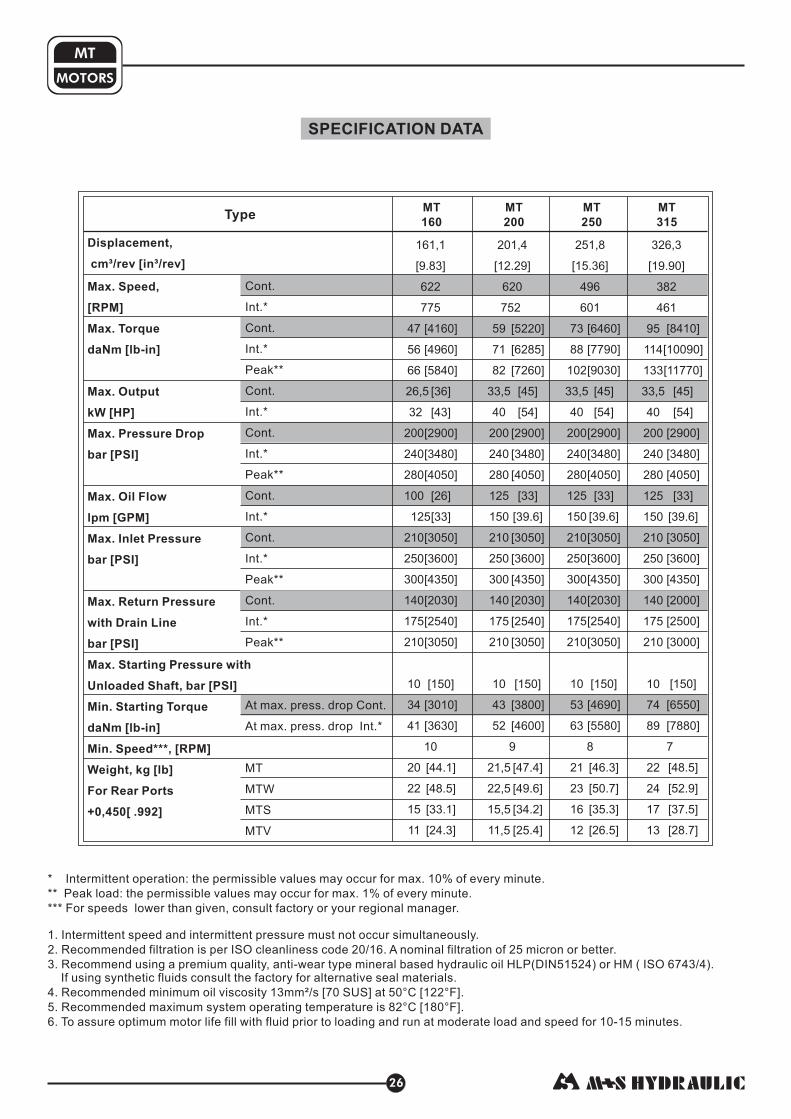
SPECIFICATION DATA
TypeMT
160
MT
200
MT
250
MT
315
[ ]
[ ]
[ ]
[ ]
[ ]
[ ]
[ 8 ]
[ ]
[ ]
[ ]
[ ]
[ ]
[ ]
[ ]
[ ]
[ ]
[ ]
[ ]
[ ]
[ ]
[ ]
[ ]
[ ]
4160
4960
5840
36
43
2900
34 0
4050
26
33
3050
3600
4350
2030
2540
3050
150
3010
3630
44.1
48.5
33.1
24.3
[ ]
622
775
47
56
66
26,5
32
200
240
280
100
125
210
250
300
140
175
210
10
34
41
10
20
22
15
11
161,1
9.83
12.29
5220
6285
7260
45
54
2900
34 0
4050
33
305
3600
4350
2030
2540
3050
150
3800
4600
47.4
49.6
34.2
25.4
[ ]
[ ]
[ ]
[ ]
[ ]
[ ]
[ 8 ]
[ ]
[ ]
[39.6]
[ 0]
[ ]
[ ]
[ ]
[ ]
[ ]
[ ]
[ ]
[ ]
[ ]
[ ]
[ ]
[ ]
[ ]
0
620
752
59
71
82
33,5
40
200
240
280
125
15
210
250
300
140
175
210
10
43
52
9
21,5
22,5
15,5
11,5
201,4
12.29
15.36
6460
7790
9030
45
54
2900
34 0
4050
33
3050
3600
4350
2030
2540
3050
150
4690
5580
46.3
50.7
35.3
26.5
[ ]
[ ]
[ ]
[ ]
[ ]
[ ]
[ ]
[ ]
[ ]
[ ]
[ ]
[ ]
[ ]
[ ]
[ ]
[ ]
[ ]
[ ]
[ ]
[ ]
[ ]
[ ]
8
[39.6]
251,8
15.36[ ]
496
601
73
88
102
33,5
40
200
240
280
125
15
210
250
300
140
175
210
10
53
63
8
21
23
16
12
0
8410
10090
11770
45
54
2900
34 0
4050
33
3050
3600
4350
2000
2500
3000
150
6550
7880
48.5
52.9
37.5
28.7
[ ]
[ ]
[ ]
[ ]
[ ]
[ ]
[ ]
[ ]
[ ]
[ ]
[ ]
[ ]
[ ]
[ ]
[ ]
[ ]
[ ]
[ ]
[ ]
[ ]
[ ]
[ ]
8
[39.6]
19.90326,3
19.90[ ]
382
461
95
114
133
33,5
40
200
240
280
125
15
210
250
300
140
175
210
10
74
89
7
22
24
17
13
0
Displacement,
Min. Speed***, [RPM]
cm³/rev [in³/rev]
Max. Speed,
[RPM]
Max. Torque
daNm [lb-in]
Max. Output
kW [HP]
Max. Pressure Drop
bar [PSI]
Max. Oil Flow
lpm [GPM]
Max. Inlet Pressure
bar [PSI]
Max. Return Pressure
with Drain Line
bar [PSI]
Max. Starting Pressure with
Unloaded Shaft, bar [PSI]
Min. Starting Torque
daNm [lb-in]
Weight, kg [lb]
+ [ ]
For Rear Ports
0,450 .992
in. /rev. [Cm. /rev.]3 3
Cont.
Int.*
Cont.
Int.*
Peak**
Cont.
Int.*
Cont.
Int.*
Peak**
Cont.
Int.*
Cont.
Int.*
Peak**
Cont.
Int.*
Peak**
At max. press. drop Cont.
At max. press. drop Int.*
MT
MTW
MTS
MTV
* Intermittent operation: the permissible values may occur for max. 10% of every minute.
** Peak load: the permissible values may occur for max. 1% of every minute.
*** For speeds lower than given, consult factory or your regional manager.
1. Intermittent speed and intermittent pressure must not occur simultaneously.
2. Recommended filtration is per ISO cleanliness code 20/16. A nominal f ltration of 25 micron or better.
3. Recommend using a premium quality, anti-wear type mineral based hydraulic oil HM ( ISO 6743/4).If using synthetic fluids consult the factory for alternative seal materials.
4. Recommended minimum oil viscosity 13mm²/s [70 SUS] at 50°C [122°F].
5. Recommended maximum system operating temperature is 82°C [180°F].
6. To assure optimum motor life fill with fluid prior to loading and run at moderate load and speed for 10-15 minutes.
i
HLP(DIN51524) or

SPECIFICATION DATA (continued)
Type
25.06
9560]
11150]
12745]
40]
47]
26 0]
3050]
34 0]
33]
3050]
3600]
4350]
2000]
2500]
3000]
150]
7435]
8585]
50.7]
55.1]
39.7]
30.9]
[
[
[
[
[
[
[
[
[
[
[
[
[
[
[
[
[
[
[
[
[
[
1
8
[39.6]
410,9
25.06
0
[ ]
304
368
108
126
144
30
35
180
210
240
125
15
210
250
300
140
175
210
10
84
97
6
23
25
18
14
31.95
10800]
12125]
14160]
36]
40]
23 0]
26 0]
3050]
33]
3050]
3600]
4350]
2000]
2500]
3000]
150]
8410]
9380]
52.9]
57.3]
41.9]
33.1]
[
[
[
[
[
[
[
[
[
[
[
[
[
[
[
[
[
[
[
[
[
[
2
1
[39.6]
523,6
31.95
0
[ ]
238
289
122
137
160
26,5
30
160
180
210
125
15
210
250
300
140
175
210
10
95
106
5
24
26
19
15
]
]
]
27]
36]
1740]
2010]
2395]
33]
3050]
3600]
4350]
2000]
2500]
3000]
150]
8410]
10180]
54.0]
58.4]
43.0]
34.2]
[11240
[13010
[15490
[
[
[
[
[
[
[
[
[
[
[
[
[
[
[
[
[
[
[
[39.6]
44.2
[ ]
1
20,2
26,8
120
140
165
125
15
210
250
300
140
175
210
10
95
115
5
24,5
26,5
19,5
15,5
724,3
44.2
72
209
127
147
175
0
1 ]
13 ]
]
33]
37]
2010]
23 0]
2760]
33]
3600]
4350]
2000]
2500]
3000]
150]
8410]
9740]
51.8]
56.2]
40.8]
32.0]
[ 1500
[ 100
[15580
[
[
[
[
[
[
[
[
[
[
[
[
[
[
[
[
[
[
[
2
[39.6]
3000]
38.52
[ ]
197
234
13
1
1
24,3
27,5
140
160
190
125
15
210
250
300
140
175
210
10
95
110
5
23,5
25,5
18,5
14,5
631,2
38.52
0
48
76
0
MT
400
MT
500
MT
725
MT
630
Displacement,
Min. Speed***, [RPM]
cm³/rev [in³/rev]
Max. Speed,
[RPM]
Max. Torque
daNm [lb-in]
Max. Output
kW [HP]
Max. Pressure Drop
bar [PSI]
Max. Oil Flow
lpm [GPM]
Max. Inlet Pressure
bar [PSI]
Max. Return Pressure
with Drain Line
bar [PSI]
Max. Starting Pressure with
Unloaded Shaft, bar [PSI]
Min. Starting Torque
daNm [lb-in]
Weight, kg [lb]
+ [ ]
For Rear Ports
0,450 .992
in. /rev. [Cm. /rev.]3 3
Cont.
Int.*
Cont.
Int.*
Peak**
Cont.
Int.*
Cont.
Int.*
Peak**
Cont.
Int.*
Cont.
Int.*
Peak**
Cont.
Int.*
Peak**
At max. press. drop Cont.
At max. press. drop Int.*
MT
MTW
MTS
MTV
MOTORS
MT
27
* Intermittent operation: the permissible values may occur for max. 10% of every minute.
** Peak load: the permissible values may occur for max. 1% of every minute.
*** For speeds lower than given, consult factory or your regional manager.
1. Intermittent speed and intermittent pressure must not occur simultaneously.
2. Recommended filtration is per ISO cleanliness code 20/16. A nominal f ltration of 25 micron or better.
3. Recommend using a premium quality, anti-wear type mineral based hydraulic oil HM ( ISO 6743/4).If using synthetic fluids consult the factory for alternative seal materials.
4. Recommended minimum oil viscosity 13mm²/s [70 SUS] at 50°C [122°F].
5. Recommended maximum system operating temperature is 82°C [180°F].
6. To assure optimum motor life fill with fluid prior to loading and run at moderate load and speed for 10-15 minutes.
i
HLP(DIN51524) or
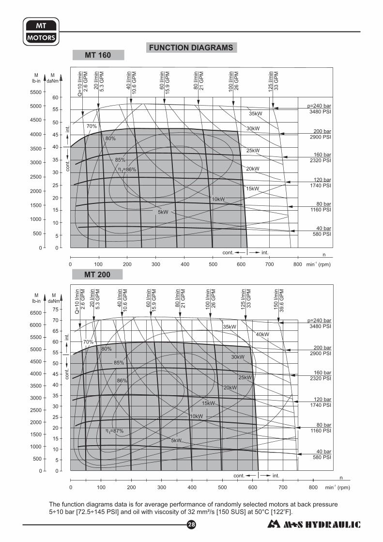
MOTORS
MT
28
MT 160
MT 200
FUNCTION DIAGRAMS
co
nt.
int.
70%
80%
85%
86%
5kW
10kW
15kW
20kW
25kW
30kW
35kW
40kW
cont. int.
40 bar
580 PSI
80 bar
1160 PSI
120 bar
1740 PSI
160 bar
2320 PSI
200 bar
2900 PSI
p=240 bar
3480 PSI
87%t=
M
lb-in
M
daNm
45
50
40
55
60
35
30
25
20
10
15
5
0
70
75
65
0
500
1000
1500
2000
2500
3000
3500
4000
4500
5000
5500
6000
6500 Q=
10
l/m
in
2.6
GP
M
20
l/m
in
5.3
GP
M
40
l/m
in
10
.6G
PM
60
l/m
in
15
.9G
PM
80
l/m
in
21
GP
M
10
0l/m
in
26
GP
M
12
5l/m
in
33
GP
M
15
0l/m
in
39
.6G
PM
0 100 200 300 400 500 600 700 800 min (rpm)-1
n
co
nt.
int. 70%
80%
85%
15kW
10kW
20kW
25kW
30kW
35kW
5kW
0 100 200 300 400 500 600 700 800 min (rpm)-1
ncont. int.
0
M
lb-in
500
1000
1500
2000
2500
3000
3500
4000
4500
5000
5500
45
50
40
55
60
35
30
25
20
10
15
5
0
M
daNmQ
=1
0l/m
in
2.6
GP
M
20
l/m
in
5.3
GP
M
40
l/m
in
10
.6G
PM
60
l/m
in
15
.9G
PM
80
l/m
in
21
GP
M
10
0l/m
in
26
GP
M
12
5l/m
in
33
GP
M
40 bar
580 PSI
80 bar
1160 PSI
120 bar
1740 PSI
160 bar
2320 PSI
200 bar
2900 PSI
p=240 bar
3480 PSI
86%t=
The function diagrams data is for average performance of randomly selected motors at back pressure
5÷10 bar [72.5÷145 PSI] and oil with viscosity of 32 mm²/s [150 SUS] at 50°C [122 F].o

MOTORS
MT
29
MT 315
MT 250
50
40
60
30
20
10
0
110
100
120
90
80
70
0
1000
2000
3000
4000
5000
6000
7000
8000
9000
10000
cont.
int.
cont. int.
40kW
35kW
30kW25kW
20kW
15kW
10kW
N=5kW88%t=
87%
85%
80%
70%
M
lb-in
M
daNm
min (rpm)-1
n
0 100 200 300 400 45035025015050
40 bar
580 PSI
80 bar
1160 PSI
120 bar
1740 PSI
160 bar
2320 PSI
200 bar
2900 PSI
p=240 bar
3480 PSI
20
l/m
in
5.3
GP
M
40
l/m
in
10.6
GP
M
Q=
10
l/m
in
2.6
GP
M
60
l/m
in
15.9
GP
M
80
l/m
in
21
GP
M
100
l/m
in
26
GP
M
125
l/m
in
33
GP
M
1l/m
in
3G
PM
50
9.6
45
50
40
55
60
35
30
25
20
10
15
5
0
95
90
85
80
70
75
65
0
500
1000
1500
2000
2500
3000
3500
4000
4500
5000
5500
6000
6500
7000
7500
8000
8500
cont.
int.
cont. int.
M
lb-in
M
daNm
min (rpm)-1
n
0 100 200 300 400 500 60055045035025015050
87%t=
70%
80%
85%
N=5kW
10kW
15kW
20kW
25kW
30kW
35kW
40kW
40 bar
580 PSI
80 bar
1160 PSI
120 bar
1740 PSI
160 bar
2320 PSI
200 bar
2900 PSI
p=240 bar
3480 PSI
20
l/m
in
5.3
GP
M
40
l/m
in
10.6
GP
M
Q=
10
l/m
in
2.6
GP
M
60
l/m
in
15.9
GP
M
80
l/m
in
21
GP
M
100
l/m
in
26
GP
M
125
l/m
in
33
GP
M
1l/m
in
3G
PM
50
9.6
The function diagrams data is for average performance of randomly selected motors at back pressure
5÷10 bar [72.5÷145 PSI] and oil with viscosity of 32 mm²/s [150 SUS] at 50°C [122 F].o
FUNCTION DIAGRAMS

MOTORS
MT
30
MT 500
MT 400
p=210 bar
3050 PSI
min (rpm)-1
n
0 100 200 300 35025015050
50
40
60
30
20
10
0
110
100
120
90
80
70
130
0
1000
2000
3000
4000
5000
6000
7000
8000
9000
10000
11000
70%
88%t=
87%
85%
80%
70%
N=2,5kW
5kW
10kW
15kW
20kW
25kW
30kW
cont.
int.
20
l/m
in
5.3
GP
M
40
l/m
in
10.6
GP
M
Q=
10
l/m
in
2.6
GP
M
60
l/m
in
15
.9G
PM
80
l/m
in
21
GP
M
100
l/m
in
26
GP
M
125
l/m
in
33
GP
M
1l/m
in
3G
PM
50
9.6
M
lb-in
M
daNm
150 bar
2175 PSI
120 bar
1740 PSI
90 bar
1160 PSI
180 bar
2610 PSI
30 bar
435 PSI
60 bar
870 PSI
p=180 bar
2610 PSI
0 50 100 150 200 250 300 min (rpm)-1
n
25 75 125 175 225 275
50
40
60
30
20
10
0
110
100
120
90
80
70
150
140
130
0
1000
2000
3000
4000
5000
6000
7000
8000
9000
10000
11000
12000
13000
cont.
int.
cont. int.
N=2,5kW
5kW 90%t= 10kW
15kW
20kW
87%
85%
80%
25kW
30kW
20
l/m
in
5.3
GP
M
40
l/m
in
10.6
GP
M
Q=
10
l/m
in
2.6
GP
M
60
l/m
in
15.9
GP
M
80
l/m
in
21
GP
M
100
l/m
in
26
GP
M
125
l/m
in
33
GP
M
1l/m
in
3G
PM
50
9.6
M
lb-in
M
daNm
30 bar
435 PSI
60 bar
870 PSI
90 bar
1160 PSI
120 bar
1740 PSI
140 bar
2030 PSI
160 bar
2320 PSI
The function diagrams data is for average performance of randomly selected motors at back pressure
5÷10 bar [72.5÷145 PSI] and oil with viscosity of 32 mm²/s [150 SUS] at 50°C [122 F].o
FUNCTION DIAGRAMS

MOTORS
MT
31
MT 630
MT 725
co
nt.
int.
cont. int.
2,5kW
5kW
10kW
75%80%
15kW
20kW
25kW
85%
87%t=
00
50
40
60
30
20
10
110
100
120
90
80
70
150
140
130
1000
2000
3000
4000
5000
6000
7000
8000
9000
10000
11000
12000
13000
16014000
M
lb-in
M
daNm
0 50 100 150 200 25025 75 125 175 225 min (rpm)-1
n
30 bar
435 PSI
60 bar
870 PSI
90 bar
1160 PSI
120 bar
1740 PSI
140 bar
2030 PSI
p=160 bar
2320 PSI
20
l/m
in
5.3
GP
M
40
l/m
in
10
.6G
PM
Q=
10
l/m
in
2.6
GP
M
60
l/m
in
15
.9G
PM
80
l/m
in
21
GP
M
10
0l/m
in
26
GP
M
12
5l/m
in
33
GP
M
1l/m
in
3G
PM
50
9.6
cont.
int.
cont. int.
20kW
73%
15kW
10kW
75%
5kW
N=2,5kW
77%
80%82%t=50
40
60
30
20
10
110
100
120
90
80
70
150
140
130
160
1000
2000
3000
4000
5000
6000
7000
8000
9000
10000
11000
12000
13000
14000
M
lb-in
M
daNm
00
0 50 100 150 20025 75 125 175 225 min (rpm)-1
n
30 bar
435 PSI
60 bar
870 PSI
90 bar
1160 PSI
120 bar
1740 PSI
p=140 bar
2030 PSI
20
l/m
in
5.3
GP
M
40
l/m
in
10.6
GP
M
Q=
10
l/m
in
2.6
GP
M
60
l/m
in
15.9
GP
M
80
l/m
in
21
GP
M
100
l/m
in
26
GP
M
125
l/m
in
33
GP
M
1l/m
in
3G
PM
50
9.6
The function diagrams data is for average performance of randomly selected motors at back pressure
5÷10 bar [72.5÷145 PSI] and oil with viscosity of 32 mm²/s [150 SUS] at 50°C [122 F].o
FUNCTION DIAGRAMS

MOTORS
MT
32
* - The width of the roll-gerotor is 3,5 mm [.138 in] greater than L .1
C
P
T
: 4xM10-10 mm [.39 in] depth: 2xG3/4 or 2xM27x2-17 mm [.67 in] depth
: G 1/4 or M14x1,5 - depth (plugged)(A,B)
12 mm [.47 in]
DIMENSIONS AND MOUNTING DATA
P(A,B)
Port B
C
T
C, CO Shaft
SL Shaft
K ShaftSH Shaft
Standard Rotation
A CW
B CCW
Viewed from Shaft EndPort Pressurized -Port Pressurized -
Reverse Rotation
A CCW
B CW
Viewed from Shaft EndPort Pressurized -Port Pressurized -
ma
x1
34
[5.2
76
]
ma
x11
4[4
.48
8]
60
[2.3
6]
ma
xL
Port A Port B
mm [in]
ma
x11
4[4
.48
8]
ma
xL
ma
x2
02
[7.9
53
]
ma
x1
82
[7.1
65
]
T75
[2.953]125
[4.621]
125[4.621]
72[2.835]
C, CO ShaftSL Shaft
K Shaft
SH Shaft
** - For Rear Ported Motors.
Type
MT 160
MT 200
MT 250
MT 315
MT 400
MT 500
MT 630
MT 725
Type
MTW 160
MTW 200
MTW 250
MTW 315
MTW 400
MTW 500
MTW 630
MTW 725
*L ,
[ ]
[ ]
[ ]
[ ]
[ ]
[ ]
[ ]
[ ]
1 mm [in]
16,5 .65
21,5 .85
27,8 1.09
37,0 1.46
47,5 1.87
61,5 2.42
57,5 2.26
66,5 2.62
L, [ ]
[ ]
[ ]
[ ]
[ ]
[ ]
[ ]
[ ]
[ ]
mm in
190 7.48
195 7.68
201 7.91
211 8.31
221 8.70
235 9.25
231 9.09
240 9.45
L,
[ ]
[ ]
[ ]
[ ]
[ ]
[ ]
[ ]
[ ]
mm [in]
123 4.84
128 5.04
134 5.28
144 5.67
154 6.06
168 6.61
164 6.46
173 6.81
L ,
[ ]
[ ]
[ ]
[ ]
[ ]
[ ]
[ ]
[ ]
2 mm [in]
140 5.51
145 5.71
151 5.95
161 6.34
171 6.73
185 7.28
181 7.13
190 7.48
L ,
[ ]
[ ]
[ ]
[ ]
[ ]
[ ]
[ ]
[ ]
2 mm [in]
73 2.87
78 3.07
84 3.31
94 3.70
104 4.09
118 4.65
114 4.49
123 4.84
** E mm [in]L ,
[ ]
[ ]
[ ]
[ ]
[ ]
[ ]
[ ]
[ ]
133 5.23
138 5.43
144 5.67
154 6.02
164 6.45
178 6.61
174 6.85
183 7.21
**L ,
[ ]
[ ]
[ ]
[ ]
[ ]
[ ]
[ ]
[ ]
E mm [in]
200 7.87
205 8.07
211 8.31
221 8.70
231 9.09
245 9.64
241 9.49
250 9.84
Flange Dim.See Page 33
Port Dim.See Page 33
Shaft Dim.See Page 34
Port A
75[2.953]
max 125
[4.921]
max 125
[4.921]
E Rear ports
ma
xL
E
L2
L1 L1
L2
ma
x1
82
[7.1
65
]

mm [in]
E Rear PortsSide Ports
33
MOTORS
MT
C
P
T
: 4xM10-10 mm [.39 in] depth: 2xG3/4 or 2xM27x2-17 mm [.67 in] depth
: G 1/4 or M14x1,5 - depth (plugged)(A,B)
12 mm [.47 in]
Square Mount (4 Holes)
W Wheel Mount
4xø14±0,1
[.551±.0039]
7
Port A
Port B
44
±0
,3
[1.7
32
±.0
11
8]
ø1
25
-0,0
63
-.0
02
5[4
.92
1]
18
[.709][6.299±.0157]
ø160±0,4
[5.63]
max 143
8
[.315]
60
[2.36]
ø7
2±
1
[2.8
35
±.0
39
]
4xø18±0,15
[.708±.0059] [7.874±.0157]
ø200±0,4
[7.087]
max 180
18
[.709]
4
[.157]
ø7
2±
1
[2.8
35
±.0
39
]
ø1
60
-0,0
63
-.0
02
5[6
.29
9]
7
[.276] max 99
[3.897]
ø1
25
-0,1
-.0
03
9[4
.92
1]
75
[2.9
53
]
ø1
72
-0,0
63
-.0
02
5[6
.77
2]
[3.079]78,2
20[.787]
20
±0
,3
[.7
87
±.0
11
8]
72
[2.835]
23±0,6
[.905±.024]
12,5±0,5
[.492±.019]
12,5±0,5[.492±.019]
12,5±0,5
[.492±.019]
12,5±0,5
[.492±.019]
20
±0
,3
[.7
87
±.0
11
8]
21
,6±
0,5
[.8
5±
.01
9]
21
,6±
0,5
[.8
5±
.01
9]
21
,6±
0,5
[.8
5±
.01
9]
21
,6±
0,5
[.8
5±
.01
9]
44
±0
,3
[1.7
32
±.0
11
8]
[.276]
72
[2.835]
C
P(A,B)
Port A
Port B
Standard Rotation
A CW
B CCW
Viewed from Shaft EndPort Pressurized -Port Pressurized -
Reverse Rotation
A CCW
B CW
Viewed from Shaft EndPort Pressurized -Port Pressurized -
MOUNTING
PORTS
[7.0
87
]
ma
x1
80
[5.6
3]
ma
x1
43

SHAFT EXTENSIONSMOTORS
MT
34
-ø1½" s 17T[11755 lb-in]
plined , DP 12/24 ANSI B92.1-1976Max. Torque 132,8 daNm
SL
KC
SH-ø1½" straight, Parallel key "x "x 2¼" BS46Max. Torque 132,8 daNm [11755 lb-in]
CO 3
8
3
8
-ø40 straight, Parallel key A12x8x70 DIN 6885Max. Torque 132,8 daNm [11755 lb-in]
-tapered 1:10, Parallel key B12x8x28 DIN 6885Max. Torque 210,7 daNm [18650 lb-in]
- p.t.o. DIN 9611 Form 1Max. Torque 77 daNm
ø34,85[6815 lb-in]
450
MAX. PERMISSIBLE SHAFT SEAL PRESSURE for MT motors
Max. return pressure without drain line ormax. pressure in the drain line
1: Drawing for Standard Shaft Seal
2: Drawing for High Pressure Seal ("U" Seal)
- continuous operations
- intermittent operations
0
20
40
60
80
100
120
0 100 200 300 400 500 600 700 800 min-1
PPSI
2
1
0
200
600
1000
Pbar
400
800
1200
1600
1400
1800
1450
1090 75
mm [in]
-.0
04
7
ø3
4,8
5-0
,12
[1.3
72
]
102[4.016 ]
7
[.28]
76 1±
[2.992±.039]
38±0,25
[1.496±.01]
ø2
9,4
±0
,1
[1.1
57
±.0
03
9]
R6,7
[.264]
8,64 -0,11
[.34 ]-.0043
A-Aø28,9-0,15
[1.138 ]-.006
ø4
5
[1.7
71
]
A
A
-0,2
-.0079
ø3
8,1
-0,0
5
[1.5
]-.
00
19
ø4
5
[1.7
71
]
82
[3.228 ]
-0,2
-.0079
9.545 -0,02
[.379 ]-.0008
min deep25 [.984]
3/8-16 UNC
42
,4-0
,2
[1.6
69
]-.
00
79
[3.228 ]
82-0,2
-.0079ø
45
[1.7
71
]
ø3
8,1
-0,0
25
[1.5
]-.
00
1
min deep25 [.984]
M12
min deep25 [.984]
M12
ø4
5
[1.7
71
]
82
[3.228 ]
-0,2
-.0079
[2.205 ]
56+2
+.079
ø4
0
+.0
00
1
+0
,00
2+
0,0
18
[1.5
75
]+
.00
07
12
[.472 ]-.0017
43
-0,2
[1.6
92
]-.
00
79
-0.043
ø4
5[1
.77
1]
5 ±0,44
[2.126±.016]
12
[.472 ]-.0017
-0.043
82±0,2
[3.228±.0079]
4
[.157]
9
[.354]
24
,15
-0,2
[.9
5]
-.0
07
9 M3
0x2
Taper 1:10
A-A
ø5
6
[2.2
05
]
A
A
ø6
,3
[.2
48
]
S=46Tightening torque
50±3 daNm[4425±265 lb-in]

96
101
107
116
127
142
138
147
DIMENSIONS AND MOUNTING DATA - MTS and MTVMOTORS
MT
35
Type
MTS 160
MTS 200
MTS 250
MTS 315
MTS 400
MTS 500
MTS 630
MTS 725
Type
MTV 160
MTV 200
MTV 250
MTV 315
MTV 400
MTV 500
MTV 630
MTV 725
L, in.[mm]
146
151
157
166
177
191
187
196
[5.75]
[5.95]
[6.18]
[6.53]
[6.97]
[7.52]
[7.36]
[7.72]
L, in.[mm]
101
106
112
121
132
146
142
151
[3.98]
[4.17]
[4.41]
[4.76]
[5.19]
[5.75]
[5.59]
[5.95]
[3.78]
[3.98]
[4.21]
[4.56]
[5.00]
[5.59]
[5.43]
[5.79]
51,5
56,5
62,8
72,0
82,5
96,5
92,5
101,5
[2.02]
[2.22]
[2.47]
[2.83]
[3.25]
[3.80]
[3.64]
[4.00]
*L , [ ]
16,5
21,5
27,8
37,0
47,5
61,5
57,5
66,5
1 mm in
[ .65]
[ .85]
[1.09]
[1.46]
[1.87]
[2.42]
[2.26]
[2.62]
**L ,mm[ in.]
156
161
167
176
187
201
197
206
E
[6.14]
[6.33]
[6.57]
[6.93]
[7.36]
[7.91]
[7.76]
[8.11]
111
116
122
131
142
156
152
161
[4.37]
[4.57]
[4.80]
[5.16]
[5.59]
[6.14]
[5.98]
[6.34]
* - The width of the roll-gerotor is 3,5 mm [.138 in] greater than L .1
** - For Rear Ported Motors.
Standard Rotation
A CW
B CCW
Viewed from Shaft EndPort Pressurized -Port Pressurized -
Reverse Rotation
A CCW
B CW
Viewed from Shaft EndPort Pressurized -Port Pressurized -
C
P
T
: 4xM10-10 mm [.39 in] depth: 2xG3/4 or 2xM27x2-17 mm [.67 in] depth
: G 1/4 or M14x1,5 - depth (plugged)(A,B)
12 mm [.47 in]
mm [in]
V Very Short MountS Short Mount
Port Dim.See Page 33
ma
xL
E
Port BPort A
T
ma
xL
Port A
"O" Ring 125x3
31
[1.2
2]
18
[.7
08
]
8
[.3
15
]
28
[1.102]min
32
,9[1
.29
5]
ma
x3
6,1
[1.4
21
]ø125 -0,063
-.0025[4.921 ]
max 125
[4.921]
P(A,B)
C
"O" Ring 100x3
67
,5
ø106
-1,9
-.0
75
[2.6
57
]
-0,12
-.0016
ma
x2
5
[.9
84
]
4xM14
ma
xL
23
±0
,1
[.9
05
±.0
03
9]
Port APort B
7
[.2
76
]
-0,04
-.0047[4.173 ]
ø105,5±0,1[4.153±.0039]
max 125
[4.921]
72
[2.8
35
]4
3[1
.69
3]
ø125
[4.921]ø6 [.236]
Drain port
ma
x1
25
[4.9
21
]
72
[2.8
35
]
4xø14,2
[.552] ø160±0,4
[6.299±.0157]
ø6
[.236]
ø6
[.236]
43
[1.6
93
]5
0[1
.96
9]
28
[1.102]
ø186
[7.323]
E Rear ports
L2
L1L
1
L2
Port B

MTS
MTV
DIMENSIONS OF THE ATTACHED COMPONENT
: Oil circulation hole
: Internal drain channel
: Hardened stop plate
F
G
H
I : O- Ring 125x3 mm [4.921x.118 in]
: 4xM12-18 mm [.71 in] depth, 90
: Drain connection G1/4 or M14x1,5
J
T
0
K: Conical seal ring
MOTORS
MT
36
DRAIN CONNECTION
A drain line ought to be used when pressure in the return line can exceed the permissible pressure. It can be
connected:
- For MTS at the drain port of the motor;
- For MTV at the drain connection of the attached component.
The drain line must be possible for oil to flow freely between motor and attached component and must be led to the
tank. The maximum pressure in the drain line is limited by the attached component and its seal.
The maximum pressure in the drain line is limited by
the attached component and its shaft seal.
: Oil circulation hole
: Internal drain channel
F
G
H
I
: Hardened stop plate
: O- Ring 100x3 mm [3.94x.12 in]
: Conical seal ringK
J
F
H
G
I
T
G
I4xM14-26 depth min
Four
Internal spline
16 DP 12/24
ANS B 92.1-1976
K
K
ø3
9±
0,5
[1.5
35
±.0
19
7]
ø5
0,5
±0
,5
[1,9
88
]±
.01
97
min
ø5
5
[2,1
65
]
min
ø6
[.2
36
]
+0
,06
3ø
12
5
46±0,3
[1.811±.0118]
[2.4
8]
+.0
19
ø6
3
[4.9
21
]
+0
,5
+.0
02
5
External Spline
16 DP 12/24
ANS B92.1-76
26±1
[1.024±.039]
ø1
32
,8±
0,2
ø1
60
±0
,4
[5.2
28
±.0
07
9]
[6.2
99
±.0
15
7]
11,2±0,2
[.441±.0079]
2,3±0,05
[.091±.002]
5
[.197]
22,5 -0,5
-.0197[.885 ]
1,5±0,4
[.059±.0157]
1,8±0,2
[.071±.0078]
69±0,4
[2.717±.0157]34,5±0,2
[1.358±.0079]
26±1
[1.024±.039]
min
ø6
[.2
36
]
Internal spline
16 DP 12/24
ANS B 92.1-1976
ø3
9±
0,5
[1.5
35
±.0
19
7]
ø5
1±
0,5
[]
2.0
08
±.0
19
7
min
ø5
5
[2,1
65
]
+0
,06
ø1
06
[4.1
73
]+
.00
24
ø1
25
±0
,2
[4.9
21
±.0
07
9]
+0
,02
+.0
00
8
R0,5
[.0197]1,6
20
0
+1,867,5
[2.657 ]+.071
+0,6
+.024
M
900
External Spline
16 DP 12/24
ANS B92.1-76
ø5
4+
0,4
[2.1
25
]+
.01
57
[3.6
2]
+.0
39
ø9
2+
1
[1.142 ]+.039
29+1
mm [in]

PERMISSIBLE SHAFT LOADS
MOTORS
MT
37
INTERNAL SPLINE DATA FOR THE ATTACHED COMPONENT
Standard ANS B92.1-1976, class 5[ corrected x.m=1]m=2.1166;
inch
16
12/24
30
1.3333
1.5118 1.5275
1.2657 1.2673
.1763 .1791
.02
1.063 1.059
.19026 .19034
°
±
±
±
±
±
mm
16
12/24
30
33,8656
38,4
32,15
4,516±0,037
0,5
26,9
°
+0,4
+0,04
+0,10
z
DP
D
Dri
Di
Lo
R
L
d
Fillet Root Side Fit
Number of Teeth
Diametral Pitch
Pressure Angle
Pitch Dia.
Major Dia.
Minor Dia.
Space Width [Circular]
Fillet Radius
Max. Measurement
between Pins
Pin Dia. 4,835±0,001
Hardening Specification:HV=750±50 on the surface.
[ ]Material: 20 MoCr4 EN 10084 or SAE8620.HV=560 at 0,7±0,2 .035±.019 case depthmm in
mm [in]
Curve " " shows max. radial shaft load. Any shaft load exceeding the values quoted in the curve will seriouslyreduce motor life.
1
The output shaft runs in tapered bearings that permit high axial and radial forces. The permissible radial load onthe shaft is shown for an axial load of 0 N as function of the distance from the mounting flange to the point ofload application. The curves apply to a B10 bearing life of 2000 hours at 100 RPM .
Prlbs
1000
2000
3000
4000
5000
6000
PrdaN
0
2000
4000
6000
0
8000
10000
12000
14000
-20-40-60-80 mm1200 20 40 60 80 100
in3.50 1 1.5 2 2.5 3.5 4 4.5-.5-1-1.5-2-2.5-3
1000 daN2250 lbs.
mm1200 20 40 60 80 100
in3.50 1 1.5 2 2.5 3.5 4 4.5
140 160 180
5 5.5 6 6.5 7 7.5
Mounting Flange:
Standard
W - Wheel

NOTES:
* The permissible output torque for shafts must not be exceeded!
ORDER CODE
The hydraulic motors are mangano-phosphatized as standard.
MOTORS
MT
38
M T
Pos.1 - Mounting Flange
Pos.2 - Port type
Pos.3 - Displacement code
1 2 3 4 5 6 7
omit - Side ports
- Rear portsE
Pos.4 - *Shaft Extensions
- ø40 straight, Parallel key A12x8x70 DIN6885
- ø1½ ” straight, Parallel key / ”x / ”x2¼” BS46
-
- ø34,85 p.t.o. DIN 9611 Form 1
- ø1½" splined 17T ANS B92.1-1976
C
CO
K
SL
SH
3 3
8 8
ø45 tapered 1:10, Parallel key B12x8x28 DIN6885
omit - Square mount, four holes
- Short mount
- Veryshort mount
- Wheel mount
S
V
W
omit - BSPP (ISO 228)
- Metric (ISO 262)M
Pos.6 - Ports
MOTORS WITH TACHO CONNECTION
Pos.8 - Design Series
omit - Factory specified
Pos.7 - Special Features (see page 51)
omit - for and mounting flangeS V
Pos.5 - Shaft Seal Version (see page 34)
omit - Low pressure seal
- High pressure sealU
8
16
5
[.197]
ø3
[.118]
33
[1.299]
max L
ø4
8
[1.8
9]
ø8
[.3
15
]
20
[.63][.787] ø34
[1.339]
4xM5
8 [.315] deep
72
[2.835]
- 61,6 cm /rev [9.83 in /rev]
- 201,4 cm /rev [12.29 in /rev]
- 251,8 cm /rev [15.36 in /rev]
- 326,3 cm /rev [19.90 in /rev]
- 410,9 cm /rev [25.06 in /rev]
- 523,6 cm /rev [31.95 in /rev]
- 631,2 c /rev [38.52 in /rev]
- 724,3 cm /rev [44.20 in /rev]
160
200
250
315
400
500
630
725
m
3 3
3 3
3 3
3 3
3 3
3 3
3 3
3 3
mm [in]
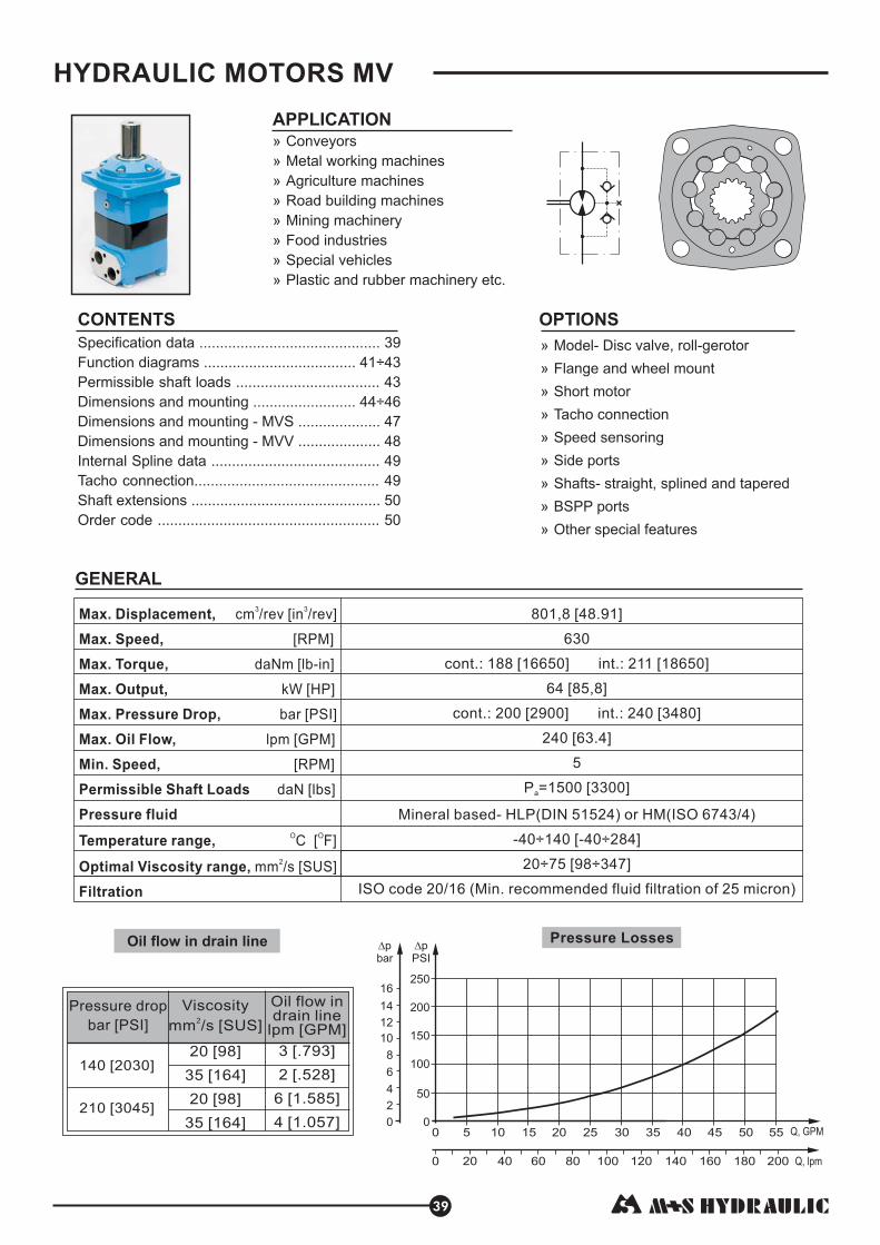
Pressure Losses
HYDRAULIC MOTORS MV
Q, GPM
Q, lpm0 20 40 60 80 100 120 140 160 180 200
0 5 10 15 20 25 30 35 40 45 50 550
50
100
150
200
250
0
2
4
6
8
10
12
14
16
APPLICATION
» Conveyors
» Metal working machines
» Road building machines
» Mining machinery
» Food industries
»
»
» Agriculture machines
Special vehicles
Plastic and rubber machinery etc.
CONTENTS OPTIONS
»
»
»
»
»
»
»
»
»
Model- Disc valve, roll-gerotor
Flange and wheel mount
Short motor
Speed sensoring
Side ports
Shafts- straight, splined and tapered
BSPP ports
Other special features
Tacho connection
140 [2030]
210 3045[ ]
Pressure drop
[ ]bar PSI
Viscosity
[ ]mm /s SUS2
Oil flow indrain line
[ ]lpm GPM
20 [98]
35 [164]
20 [98]
35 [164]
3 [.793]
.528
1.585
[1.057]
2 [ ]
6 [ ]
4
Oil flow in drain line
Max. Displacement,
Max. Speed,
Max. Torque,
Max. Output,
Max. Pressure Drop,
Max. Oil Flow,
Min. Speed,
Permissible Shaft Loads
Pressure fluid
Temperature range,
Optimal Viscosity range,
Filtration
cm /rev [in /rev]
[RPM]
daNm [lb-in]
kW [HP]
bar [PSI]
lpm [GPM]
[RPM]
daN [lbs]
C [ F]
mm /s [SUS]
3 3
O O
2
801,8 48.91
188 16650
64 85,8
200 2900
1500 3300
20÷75 98÷347
[ ]
630
cont.: [ ] int.: 211 [18650]
[ ]
cont.: [ ] int.: 240 [3480]
240 [63.4]
5
P = [ ]
Mineral based- HLP(DIN 51524) or HM(ISO 6743/4)
[ ]
ISO code 20/16 (Min. recommended fluid filtration of 25 micron)
a
-40÷140 [-40÷284]
GENERAL
39
Specification data ........... .. ...
............ ... ÷
Order code .................. . ......
..... ....................... 39
Function diagrams ...................... 41 43
Permissible shaft loads ................................... 43
Dimensions and mounting ......................... 44÷46
Dimensions and mounting - MVS .................... 47
Dimensions and mounting - MVV .................... 48
Internal Spline data ......................................... 49
Tacho connection............................................. 49
Shaft extensions .............................................. 50
............................ . 50

TypeMV
315
314 5
19.18
92 8150
111 9800
129 11400
42,5 57
51 68.4
200 2900
240 3 0
280 4 0
160 42
200 5
210 30 0
250 36 0
300 4 0
60 870
30 435
75 1100
140 20 0
175 25 0
210 30
71 6300
85 7500
31,8 70.1
32,4 71.4
22,7 50
,
[ ]
510
630
[ ]
[ ]
[ ]
[ ]
[ ]
[ ]
[ 48 ]
[ 06 ]
[ .3]
[ 2.8]
[ 5 ]
[ 2 ]
[ 35 ]
[ ]
[ ]
20 [290]
[ ]
[ 4 ]
[ 4 ]
[ 50]
8 [120]
[ ]
[ ]
10
[ ]
[ ]
[ ]
400,9
24.45
118 10450
141 12500
164 14500
53,5 71.7
64 85.8
200 [2900]
240 [3480]
280 [4060]
200 5
240 63
210 [3050]
250 [3620]
300 [4350]
60 [870]
30 [435]
2 [290]
75 [1100]
140 [2040]
175 [2540]
210 [3050]
8 [120]
91 8100
109 9600
32,6 71.9
33,2 73.2
23,5 51.8
[ ]
500
600
[ ]
[ ]
[ ]
[ ]
[ ]
[ 2.8]
[ .4]
0
[ ]
[ ]
9
[ ]
[ ]
[ ]
499,6
30.48
146 12950
176 15550
205 18150
53,5 71.7
64 85.8
200 [2900]
240 [3480]
280 [4060]
200 [52.8]
240 [63.4]
210 [3050]
250 [3620]
300 [4350]
60 [870]
30 [435]
2 [290]
75 [1100]
140 [2040]
175 [2540]
210 [3050]
8 [120]
113 10000
136 12000
33,5 73.8
34,1 75.2
24,4 53.8
[ ]
400
480
[ ]
[ ]
[ ]
[ ]
[ ]
0
[ ]
[ ]
8
[ ]
[ ]
[ ]
629,1
38.38
166 14700
194 17150
221 19550
48 64.4
56 75
180 26 0
210 3050
240 3 0
200 [52.8]
240 [63.4
210 [3050]
250 [3620]
300 [4350]
60 [870]
30 [435]
2 [290]
75 [1100]
140 [2040]
175 [2540]
210 [3050]
8 [120]
133 11800
155 13700
34,9 76.9
35,5 78.3
25,6 56.4
[ ]
320
380
[ ]
[ ]
[ ]
[ ]
[ ]
[ 1 ]
[ ]
[ 48 ]
0
[ ]
[ ]
6
[ ]
[ ]
[ ]
801,8
48.91
188 16650
211 18650
247 21850
42,5 57
48 64.4
160 23 0
180 26 0
210 3050
200 [52.8]
240 [63.4
210 [3050]
250 [3620]
300 [4350]
60 [870]
30 [435]
2 [290]
75 [1100]
140 [2040]
175 [2540]
210 [3050]
8 [120]
151 13400
170 15000
36,5 80.5
37,1 81.8
27,7 61.1
[ ]
250
300
[ ]
[ ]
[ ]
[ ]
[ ]
[ 2 ]
[ 1 ]
[ ]
]
0
[ ]
[ ]
5
[ ]
[ ]
[ ]
MV
400
MV
500
MV
630
MV
800
Displacement,
[ ]
Max. Speed,
[RPM]
Max. Torque
[ ]
Max. Output
[ ]
Max. Pressure Drop
[ ]
Max. Oil Flow
[ ]
Max. Inlet Pressure
[ ]
Max. Return Pressure
with Drain Line
[ ]
Max. Starting Pressure with
Unloaded Shaft, [ ]
Min. Starting Torque
[ ]
Min. Speed***, [RPM]
Weight, [ ]
cm /rev In /rev
daNm lb-in
kW HP
bar PSI
lpm GPM
bar PSI
bar PSI
bar PSI
daNm lb-in
kg lb
3 3
Max. Return Pressure
without Drain Line or
Max. Pressure
in Drain Line, [ ]bar PSI
Cont.
Int.*
Cont.
Int.*
Peak**
Cont.
Int.*
Cont.
Int.*
Peak**
Cont.
Int.*
Cont.
Int.*
Peak**
Cont. 0-100 RPM
Cont. 100-300 RPM
Cont. >300 RPM
Int.* 0-max. RPM
Cont.
Int.*
Peak**
At max. press. drop Cont.
At max. press. drop Int.*
MV
MVW
MVS
SPECIFICATION DATA
MLHV
MOTORS
MV
40
* Intermittent operation: the permissible values may occur for max. 10% of every minute.
** Peak load: the permissible values may occur for max. 1% of every minute.
*** For speeds lower than given, consult factory or your regional manager.
1. Intermittent speed and intermittent pressure must not occur simultaneously.
2. Recommended filtration is per ISO cleanliness code 20/16. A nominal f ltration of 25 micron or better.
3. Recommend using a premium quality, anti-wear type mineral based hydraulic oil HM ( ISO 6743/4).
If using synthetic fluids consult the factory for alternative seal materials.
4. Recommended minimum oil viscosity 13mm²/s [70 SUS] at 50°C [122°F].
5. Recommended maximum system operating temperature is 82°C [180°F].
6. To assure optimum motor life fill with fluid prior to loading and run at moderate load and speed for 10-15 minutes.
i
HLP(DIN51524) or

M
daNm
0
0 15050 200 250100 300 350 400 450 500 550 min (rpm)-1
n
20
40
60
80 cont.
cont.
int.
int.
100
120
140
160
600
Q=
10
l/m
in
0
0 15050 200 250100 300 350 400 450 500 550 650
p=240 bar
200 bar
175 bar
140 bar
105 bar
70 bar
35 bar
min (rpm)-1
n
20
40
60
80
cont.
cont.
int.
int.
100
120
600
25
l/m
in
30 kW
40 kW50 kW
N=5 kW
10 kW
20 kW
80%
70%
85%
MV 315
MV 400
FUNCTION DIAGRAMS
MOTORS
MV
N=5 kW 10 kW
20 kW
30 kW
40 kW
50 kW
85%
80%
70%
87%
41
2.6
GP
M
6.6
GP
M
50
l/m
in
13.2
GP
M
75
l/m
in
19.8
GP
M
100
l/m
in
26.4
GP
M
125
l/m
in
33
GP
M
150
l/m
in
39.6
GP
M
160
l/m
in
42.3
GP
M
200
l/m
in
52.8
GP
M
3480 PSI
2900 PSI
2540 PSI
2030 PSI
1520 PSI
1020 PSI
510 PSI
0
1000
2000
3000
4000
5000
6000
7000
8000
9000
10000
11000
M
lb-in
M
daNm
25
l/m
in
2.6
GP
M
6.6
GP
M
50
l/m
in
13.2
GP
M
75
l/m
in
19.8
GP
M
100
l/m
in
26.4
GP
M
125
l/m
in
33
GP
M
150
l/m
in
39.6
GP
M
175
l/m
in
46.2
GP
M
200
l/m
in
52.8
GP
M
Q=
10
l/m
in
240
l/m
in
63.4
GP
M
p=240 bar
200 bar
175 bar
140 bar
105 bar
70 bar
35 bar
3480 PSI
2900 PSI
2540 PSI
2030 PSI
1520 PSI
1020 PSI
510 PSI0
M
lb-in
1000
2000
3000
4000
5000
6000
7000
8000
9000
10000
11000
12000
13000
14000
15000
The function diagrams data is for average performance of randomly selected motors at back pressure
5÷10 bar [72.5÷145 PSI] and oil with viscosity of 32 mm²/s [150 SUS] at 50°C [122 F].o
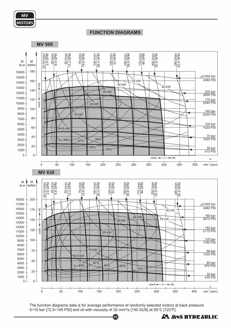
M
daNm
0
0 15050 200 250100 300 350 400 450 500 min (rpm)-1
n
20
40
60
80
cont.
cont.
int.
int.
100
120
140
160
180
M
daNm
0
0 15050 200 250100 300 350 400 min (rpm)-1
n
25
50
75
cont.
cont.
int.
int.
100
125
150
175
200
MOTORS
MV
MV 500
MV 630
N=5 kW
10 kW
20 kW
30 kW
40 kW60 kW
85%
80%70%
87%
50 kW
N=5 kW
10 kW
20 kW
30 kW
40 kW
60 kW
85% 80%
70%
87%
50 kW
FUNCTION DIAGRAMS
42
M
lb-in
0
1000
2000
3000
4000
5000
6000
7000
8000
9000
10000
11000
12000
13000
14000
15000
16000
p=240 bar
200 bar
175 bar
140 bar
105 bar
70 bar
35 bar
3480 PSI
2900 PSI
2540 PSI
2030 PSI
1520 PSI
1020 PSI
510 PSI
p=240 bar
180 bar
3480 PSI
2610 PSI
150 bar
2175 PSI
120 bar
1740 PSI
90 bar
1305 PSI
60 bar
870 PSI
30 bar
435 PSI
Q=
10
l/m
in
2.6
GP
M
25
l/m
in
6.6
GP
M
50
l/m
in
13.2
GP
M
75
l/m
in
19.8
GP
M
100
l/m
in
26.4
GP
M
125
l/m
in
33
GP
M
150
l/m
in
39.6
GP
M
175
l/m
in
46
GP
M
200
l/m
in
52.8
GP
M
240
l/m
in
63.4
GP
M
Q=
10
l/m
in
2.6
GP
M
25
l/m
in
6.6
GP
M
50
l/m
in
13.2
GP
M
75
l/m
in
19.8
GP
M
100
l/m
in
26.4
GP
M
125
l/m
in
33
GP
M
150
l/m
in
39.6
GP
M
175
l/m
in
46
GP
M
200
l/m
in
52.8
GP
M
240
l/m
in
63.4
GP
M
0
M
lb-in
1000
2000
3000
4000
5000
6000
7000
8000
9000
10000
11000
12000
13000
14000
15000
16000
17000
18000
The function diagrams data is for average performance of randomly selected motors at back pressure
5÷10 bar [72.5÷145 PSI] and oil with viscosity of 32 mm²/s [150 SUS] at 50°C [122 F].o

-20-40-60-80 mm
mm
Prlbs
1000
2000
3000
4000
5000
6000
PrdaN
0120 160 180 200
0
0
20
20
40
40
60
60
80
80
100 110
100 140
7000
8000
9000
10000
in3.50 1 1.5 2 2.5 3
2000
4000
6000
0
8000
10000
.5 4 4.5
in3.5 5 6.50 1 1.5 2 2.5 3.5 4 5.5 74.5 6 7.5 8
-.5-1-1.5-2-2.5-3
12000
14000
16000
18000
20000
22000
1
-3.5
MdaNm
0
0 15050 200 250100 300 min (rpm)-1
n
25
50
75
cont.
cont.
int.
int.
100
125
150
175
200
225
MOTORS
MV
MV 800
PERMISSIBLE SHAFT LOADS
Curve " " shows max. radial shaft load. Any shaft load exceeding the values quoted in the curve will seriouslyreduce motor life.
1
N=5 kW
10 kW
20 kW
30 kW
40 kW
80%
70%
85%
FUNCTION DIAGRAMS
43
Q=
10
l/m
in2.6
GP
M
25
l/m
in6.6
GP
M
50
l/m
in
13.2
GP
M
75
l/m
in19.8
GP
M
100
l/m
in
26.4
GP
M
125
l/m
in
33
GP
M
150
l/m
in39.6
GP
M
175
l/m
in46
GP
M
200
l/m
in52.8
GP
M
240
l/m
in63.4
GP
M
p=180 bar
160 bar
2610 PSI
2320 PSI
130 bar1885 PSI
100 bar1450 PSI
75 bar1090 PSI
50 bar720 PSI
25 bar360 PSI
Mlb-in
0
1000
2000
3000
4000
5000
6000
7000
8000
9000
10000
11000
12000
13000
14000
15000
16000
17000
18000
19000
20000
The function diagrams data is for average performance of randomly selected motors at back pressure5÷10 bar [72.5÷145 PSI] and oil with viscosity of 32 mm²/s [150 SUS] at 50°C [122 F].
o
The output shaft runs in tapered bearings that permit high axial and radial forces. The permissible radial load onthe shaft is shown for an axial load of 0 N as function of the distance from the mounting flange to the point of loadapplication. The curves apply to a B10 bearing life of 2000 hours at 100 RPM .
-20-40-60 mm120 1400 20 40 60 80 100
in3.50 1 1.5 2 2.5 3.5 4 4.5 5 5.5-.5-1-1.5-2-2.5
1500 daN3370 lbs.
Mounting Flange:
Standard
W - Wheel
SAE C

44
MOTORS
MV
DIMENSIONS AND MOUNTING DATA - MV and MVC
Standard Rotation
A CW
B CCW
Viewed from Shaft End
Port Pressurized -
Port Pressurized -
Reverse Rotation
A CCW
B CW
Viewed from Shaft End
Port Pressurized -
Port Pressurized -mm [in]
Flange Dim.
See Page 46
Port Dim.
See Page 46
Shaft Dim.
See Page 50
Type
MV 315
MV 400
MV 500
MV 630
MV 800
Type
MVC 315
MVC 400
MVC 500
MVC 630
MVC 800
L, [ ]
[ ]
[ ]
[ ]
[ ]
[ ]
mm in
214,5 8.45
221,5 8.72
229,5 9.04
240,0 9.45
254,0 10.0
L , [ ]
[ ]
[ ]
[ ]
[ ]
[ ]
2 mm in
160 6.30
167 6.58
175 6.89
186 7.32
200 7.87
* The width of the gero or is [ ] greater than L .roll- t 14 mm .157 in.
L, [ ]
[ ]
[ ]
[ ]
[ ]
[ ]
mm in
238,25 9.38
245,25 9.66
253,25 9.97
263,75 10.38
277,75 10.94
L , [ ]
[ ]
[ ]
[ ]
[ ]
[ ]
2 mm in
184,26 7.25
191,26 7.53
199,26 7.85
209,76 8.25
223,76 8.81
SH Shaft
K Shaft
C Shaft CO Shaft
10
5[4
.13
4]
82
[3.2
28
]
82
[3.2
28
]
40
[1.5
75
]
60
[2.3
62
]
ma
xL m
ax
L
85
[3.3
46
]
82
[3.2
28
]
10
5[4
.13
4]
82
[3.2
28
]
SH Shaft
K Shaft
C Shaft CO Shaft
max 145 [5.709]max 145 [5.709]
[ ]
[ ]
[ ]
[ ]
[ ]
22,0 .87
29,0 1.14
37,0 1.46
47,5 1.87
61,5 2.42
*L , [ ]1 mm in
C
P
T
: 4xM12 - 12 mm [.47 in] depth
: 2xG1 - 20 mm [.79 in] depth
: G 1/4 - 12 mm [.47 in] depth
(A,B)
P(A,B)
Port B
C
T
Port A
P(A,B)
T
C
Port B
Port A
L2
L1
L2
L1
[.5
51
]
14
+0
, 2
+. 0
07
8
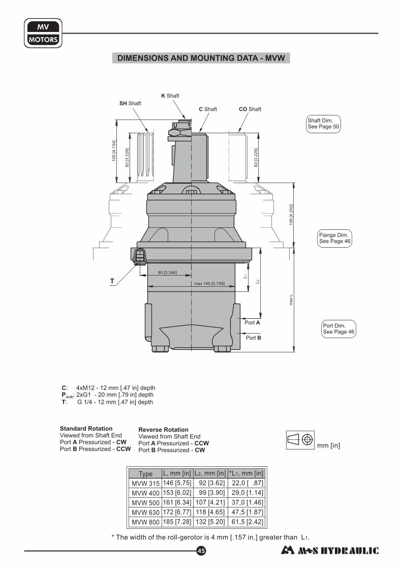
45
MOTORS
MV
DIMENSIONS AND MOUNTING DATA - MVW
Flange Dim.
See Page 46
Port Dim.
See Page 46
Shaft Dim.
See Page 50
10
5[4
.13
4]
82
[3.2
28
]
82
[3.2
28
]
10
8[4
.25
2]
ma
xL
SH Shaft
K Shaft
C Shaft CO Shaft
85 [3.346]
L, [ ]
[ ]
[ ]
[ ]
[ ]
[ ]
mm in
146 5.75
153 6.02
161 6.34
172 6.77
185 7.28
L , [ ]
[ ]
[ ]
[ ]
[ ]
[ ]
2 mm in
92 3.62
99 3.90
107 4.21
118 4.65
132 5.20
*L , [ ]
[ ]
[ ]
[ ]
[ ]
[ ]
1 mm in
22,0 .87
29,0 1.14
37,0 1.46
47,5 1.87
61,5 2.42
* The width of the gero or is [ ] greater than L .roll- t 14 mm .157 in.
Type
MVW 315
MVW 400
MVW 500
MVW 630
MVW 800
max 145 [5.709]
Standard Rotation
A CW
B CCW
Viewed from Shaft End
Port Pressurized -
Port Pressurized -
Reverse Rotation
A CCW
B CW
Viewed from Shaft End
Port Pressurized -
Port Pressurized -mm [in]
C
P
T
: 4xM12 - 12 mm [.47 in] depth
: 2xG1 - 20 mm [.79 in] depth
: G 1/4 - 12 mm [.47 in] depth
(A,B)
T
Port B
Port A
L2
L1

46
Square Mount (4 Holes)
W Wheel Mount
MOTORS
MV
T
T
C SAE C Mount
T
max 179
[7.047]
ma
x1
79
[7.0
47
]
4xø14,3
[.563]
ø162±0,4
[6.378±.0157]
60 40
[2.362] [1.575]
20 11
[.433][.787]
69
[2.7
17
]
147
[5.787]
14
7
[5.7
87
]
15
7
[6.1
81
]
4xø18
[.708]
ø200±0,4
[7.874±.0157]
85
[3.346]
[.551 ]
14
ø8
9±
1
20
[.787]
108
[4.252]
20
[.787]
10
[.394]
3,6 79
[.142] [3.11]
ø8
9±
1
ma
x1
98
[7.7
95
]
max 198
[7.795]
4xø18
[.708]
ø224±0,4
[8.819±.0157]
85
[3.3
46
]
[3.5
04
±.0
39
4]
[3.5
04
±.0
39
4]
Standard Rotation
A CW
B CCW
Viewed from Shaft End
Port Pressurized -
Port Pressurized -
Reverse Rotation
A CCW
B CW
Viewed from Shaft End
Port Pressurized -
Port Pressurized -
C
P
T
: 4xM12 - 12 mm [.47 in] depth
: 2xG1 - 20 mm [.79 in] depth
: G 1/4 - 12 mm [.47 in] depth
(A,B)
Side Ports
P(A, B)
C
13,5±0,5
[.531±.0197]
13,5±0,5
[.531±.0197]
23
,4±
0,5
[.9
21
±.0
19
7]
23
,4±
0,5
[.9
21
±.0
19
7]
25
±0
,3
[.9
84
±.0
11
8]
25
±0
,3
[.9
84
±.0
11
8]
13,5±0,5
[.531±.0197]
13,5±0,5
[.531±.0197]
24±0,6
[.945±.0236]
23
,4±
0,5
[.9
21
±.0
19
7]
23
,4±
0,5
[.9
21
±.0
19
7]
81
[3.189]
ø1
80
-0,0
63
-.0
02
5[7
.08
7]
ø1
48
-0,1
-.0
03
9[5
.82
7]
ø1
94
-0,0
72
-.0
02
8[7
.63
8]
ø1
60
-0,0
63
-.0
02
5[6
.29
9]
ø1
27
-0,0
5
-.0
01
9[5
.0]
mm [in]
+0,2
+.0078
MOUNTING
PORTS

DIMENSIONS AND MOUNTINGMOTORS
MV
S Short Mount
MVS
DIMENSIONS OF THE ATTACHED COMPONENT
: Oil circulation hole
: Internal drain channel
F
G
H
I
: Hardened stop plate
: O-Ring 140x3mm [5.512x.118in]
: 4xM12-18 mm [.709 in] depth, 90
: Drain connection G1/4 - 12 mm [.47 in] depth
J
T
0
K: Conical seal ring
47
P(A,B)
C
T
Port A Port B
K
C:
P :
T:
4xM12 - 12 mm [.47 in] depth
2xG1 - 20 mm [.79 in] depth
G 1/4 - 12 mm [.47 in] depth
(A,B)
* The width of the gero or is [ ] greater than L .roll- t 14 mm .157 in
ø207
[8.150]
ø140
[5.112 ]
28
[1.102]
51
ma
x
[2.0
08
]
35
[1.3
78
]
20
8
[.7
87
][.
31
5]
24
±0
,6
[.9
45
±.0
23
6]
13
,5±
0,5
[.5
31
±.0
19
7]
13
,5±
0,5
[.5
31
±.0
19
7]
[.921±.0197]
23,4±0,5
25±0,3
[.984±.0118]
25±0,3
[.984±.0118]
[.921±.0197]
23,4±0,5[.921±.0197]
23,4±0,5
[.921±.0197]
23,4±0,5
“O” Ring 140x3
Involute Spline
16 DP 10/20
ANS B92.1-1976
Drain port
ø6 [.236]
*L , [ ]
[ ]
[ ]
[ ]
[ ]
[ ]
1 mm in
22,0 .87
29,0 1.14
37,0 1.46
47,5 1.87
61,5 2.42
L , [ ]
[ ]
[ ]
[ ]
[ ]
[ ]
2 mm in
117 4.61
124 4.88
132 5.20
143 5.63
157 6.18
L, [ ]
[ ]
[ ]
[ ]
[ ]
[ ]
mm in
171 6.73
179 7.05
186 7.32
197 7.76
211 8.31
Type
MVS 315
MVS 400
MVS 500
MVS 630
MVS 800
84
[3.307]
ma
xL
81max 77
584xø14
[3.0315] [3.189]
[2.283][.551]
[7.0
87
±.0
15
7]
ø1
80
±0
,4
Internal Spline
16 DP 10/20
ANS B92.1-1976
[1.1
02
]
28
30±0,5
[1.181±.0197]
G
IT
[7.0
87
±.0
15
7]
ø1
80
±0
,4
[5.8
19
±.0
03
9]
ø1
47
,8±
0,1
min
ø6
0
[2.3
62
]
ø4
6±
0,2
[1.8
11
±.0
07
8]
J
2,3±0,05
[.0905±.00196]min 18
[.7087]
H
F32±0,5
[1.26±.0197]
0,25 K
0,1 K
9±0,5
[.354±.0197]
53±0,3
[2.087±.0118]
76±0,3
[2.992±.0118]
[5.512x.118in]
min
ø6
[.2
36
]
+.0
02
5
+.0
51
2
+1
,3ø
55
[2.1
65
]
+.0
15
7[4
.33
]
+0
,4ø
11
0
[5.1
12
]
+0
,06
3ø
14
0
mm [in]
-0,063
-.0025
Standard Rotation
A CW
B CCW
Viewed from Shaft End
Port Pressurized -
Port Pressurized -
Reverse Rotation
A CCW
B CW
Viewed from Shaft End
Port Pressurized -
Port Pressurized -
L2
L1
+.0
19
7[2
.59
8]
+0
,5ø
66
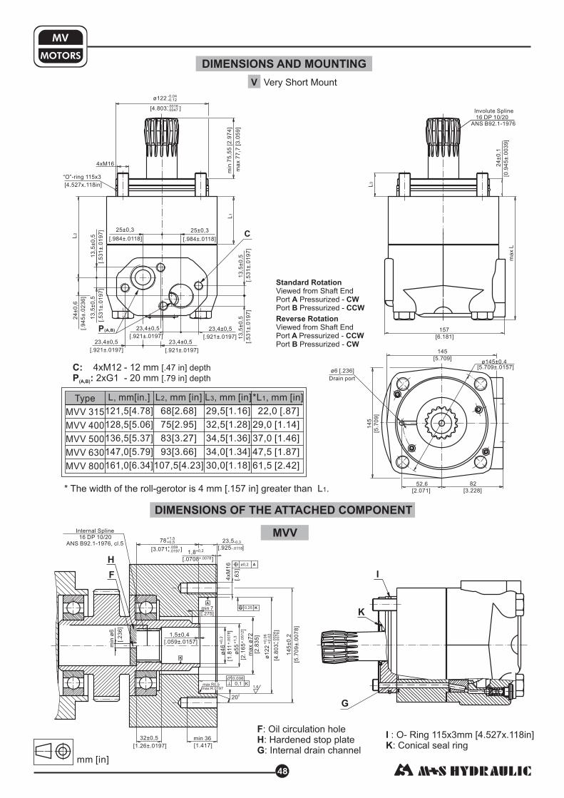
DIMENSIONS AND MOUNTINGMOTORS
MV
V Very Short Mount
* The width of the roll-gerotor is 4 mm [.157 in] greater than L .1
C:
P :
4xM12 - 12 mm
2xG1 - 20 mm
[.47 in] depth
[.79 in] depth(A,B)
MVV
DIMENSIONS OF THE ATTACHED COMPONENT
: O- Ring 115x3mm [4.527x.118in]
: Conical seal ring
I
K
C
48
F
H
G
: Oil circulation hole
: Hardened stop plate
: Internal drain channel
F
H
I
K
Involute Spline
16 DP 10/20
ANS B92.1-1976
Drain port
ø6 [.236]
*L , [ ]
[ ]
[ ]
[ ]
[ ]
[ ]
1 mm in
22,0 .87
29,0 1.14
37,0 1.46
47,5 1.87
61,5 2.42
Type
MVV 315
MVV 400
MVV 500
MVV 630
MVV 800
L, [ ]
[ ]
[ ]
[ ]
[ ]
[ ]
mm in.
121,5 4.78
128,5 5.06
136,5 5.37
147,0 5.79
161,0 6.34
L , [ ]
[ ]
[ ]
[ ]
[ ]
[ ]
2 mm in
68 2.68
75 2.95
83 3.27
93 3.66
107,5 4.23
L , [ ]
[ ]
[ ]
[ ]
[ ]
[ ]
3 mm in
29,5 1.16
32,5 1.28
34,5 1.36
34,0 1.34
30,0 1.18
4xM16
“O”-ring 115x3
ø122-0,04
-0,12
[4.803 ]-.0016
-.0047
min
75
,55
[2.9
74
]
ma
x7
7,7
[3.0
59
]
24
±0
,1
[0.9
45
±.0
03
9]
ma
xL
157
[6.181]
145
[5.709]
82
[3.228]
52,6
[2.071]
14
5
[5.7
09
]
ø145±0,4
[5.709±.0157]
[.921±.0197]
23,4±0,5
[.921±.0197]
23,4±0,5
[.921±.0197]
23,4±0,5
[.921±.0197]
23,4±0,5
25±0,3
[.984±.0118]
25±0,3
[.984±.0118]
24
±0
,6
[.9
45
±.0
23
6]
13
,5±
0,5
[.5
31
±.0
19
7]
13
,5±
0,5
[.5
31
±.0
19
7]
[4.527x.118in]
G
min
ø6
[.2
36
]
1,5±0,4
[.059±.0157]
K
A
78+1,5
+0,5
[3.071 ]+.059
+.0197
K
Aø0,2
0,25
Internal Spline
16 DP 10/20
ANS B92.1-1976, cl.5
32±0,5
[1.26±.0197]
min 36
[1.417]
1,6
200
max R0,5
max R.0197
23,5-0,3
[.925 ]-.0118
1,8+0,2
[.0708 ]+.0078
min 7
[.275]
4xM
16
[.6
3]
K0,1
0,006
14
5±
0,2
[5.7
09
±.0
07
8]
+1
,3
+0
,02
[4.8
03
]+
.00
24
+.0
07
8
ma
xø
72
[2.8
35
]
[2.1
65
]+
.05
12
ø5
5
ø1
22
+0
,06
ø4
6+
0,2
[1.8
11
]+
.00
78
mm [in]
13
,5±
0,5
[.5
31
±.0
19
7]
13
,5±
0,5
[.5
31
±.0
19
7]
P(A,B)
L2
L1
L3
Standard Rotation
A CW
B CCW
Viewed from Shaft End
Port Pressurized -
Port Pressurized -
Reverse Rotation
A CCW
B CW
Viewed from Shaft End
Port Pressurized -
Port Pressurized -

MOTORS
MV
49
INTERNAL SPLINE DATA FOR THE ATTACHED COMPONENT
Standard ANS B92.1-1976, class 5[m=2.54; ]corrected x.m=+1,0
L
MOTOR WITH TACHO CONNECTION
DRAIN CONNECTION
A drain line ought to be used when pressure in the return line can exceed the permissible pressure. It can be
connected:
- For MVS at the drain port of the motor;
- For MVV at the drain connection of the attached component.
The drain line must be possible for oil to flow freely between motor and attached component and must be led to the
tank. The maximum pressure in the drain line is limited by the attached component and its seal.
The maximum pressure in the drain line is limited by
the attached component and its shaft seal.
Hardening Specification:HV=750±50 on the surface.
[ ]
Material: 20 MoCr4 EN 10084 or .
HV=560 at 0,7±0,2 .035±.019 case depthmm in
better
16
5
[.197]
ø3
[.118]
33
[1.299]
max L
ø4
8
[1.8
9]
ø8
[.3
15
]
20
[.63][.787]
ø34
[1.339]
4xM5
8 [.315] deep
inch
16
10/20
30
1.6
1.796÷1.780
1.5175÷1.516
.2055÷.2025
.015
1.284÷1.278
.22051÷.22043
0
mm
16
10/20
30
40,640
45,2
38,5
5,18±0,037
0,4
32,47
0
+0,4
+0,039
+0,15
z
DP
D
Dri
Di
Lo
R
L
d
Fillet Root Side Fit
Number of Teeth
Diametral Pitch
Pressure Angle
Pitch Dia.
Major Dia.
Minor Dia.
Space Width [Circular]
Fillet Radius
Max. Measurement
between Pins
Pin Dia. 5,6±0,001
mm [in]
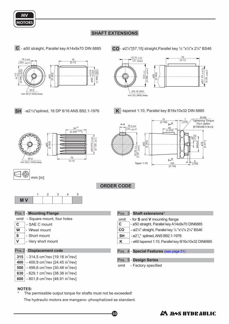
MOTORS
MV
50
omit - for and mounting flange
- ø50 straight, Parallel key A14x9x70 DIN6885
- ø2 " straight,
- ø2 / " splined,ANS B92.1-1976
-
S V
C
CO
SH
K
¼ Parallel key ½ "x½"x 2¼" BS46
1
8
ø60 tapered 1:10, Parallel key B16x10x32 DIN6885
M V
ORDER CODE
Pos.1 - Mounting Flange
Pos.2 - Displacement code
1 2 3 4 5
Pos. 3 - *Shaft extensions
NOTES:
* The permissible output torque for shafts must not be exceeded!
omit - Square mount, four holes
- SAE C mount
- Wheel mount
- Short mount
- Very short mount
C
W
S
V
SHAFT EXTENSIONS
C - ø50 straight, Parallel key A14x9x70 DIN 6885
K -tapered 1:10, Parallel key B16x10x32 DIN 6885
The hydraulic motors are mangano- phosphatized as standard.
CO - ø2 "[57,15] straight,Parallel key "x "x 2¼" BS46¼ ½ ½
-ø2 / "splined, 16 DP 8/16 ANS B92.1-19761 8SH
Pos. 5 - Design Series
omit - Factory specified
Pos. 4 - Special Features (see page 51)
53
+0
,5
+0
,2
14 -0,043
ø6
0
79
ø5
0+
0,0
18
+0
,00
2
M12
min 26 [1.024] deep
[2.0
86
]+
.01
97
[.551 ]-.0017
[2.3
62
]
[3.11]
+.0
07
9
[1.9
68
]+
.00
07
+.0
00
1
12,72 -0,02
[.5 ]-.0008
3/8-16 UNC
min 25 [.984] deep
62
,90
,2-
[2.0
86
]-.
00
79
79
[3.11]
ø7
,15
5-
15
0,0
[2.2
5]
-.0
00
6
ø6
0
[2.3
62
]
ø6
0
[2.3
62
]
ø6
0
[2.3
62
]
16-0,043
[.63 ]-.0017
M12
min 26 [1.024] deep
ø5
3,9
75
0,
2-
05
[2.1
25
]-.
00
1
79
[3.11]
56+2
[2.205 ]+.078
32
,25
0,2
-
[1.2
7]
-.0
07
9
70
[2.756]
7
[ 275].
40
[1.575]
105
[4.134]
6
[.236]
ø7
8
[]
3.0
71
M4
2x3
ø8
[]
.31
5
A
AA-A
- 314,5 cm /rev [19.18 in /rev]
- 400,9 cm /rev [24.45 in /rev]
- 499,6 cm /rev [30.48 in /rev]
- 629,1 cm /rev [38.38 in /rev]
- 801,8 cm /rev [48.91 in /rev]
315
400
500
630
800
3 3
3 3
3 3
3 3
3 3
S=65
Tightening Torque
70±1 daNm
[6196±88.5 lb-in]
Taper 1:10
mm [in]

51
MOTOR SPECIAL FEATURES
Special
Feature
Description
Order
Code
Tacho Connection**
Low Leakage
Low Speed Valving
Reverse Rotation
Paint***
Corrosion
Protected Paint***
RS
T
LL
LSV
R
P
PC
MS
MT
O O
O O
O O
O O
O O
O O
O O
Motor type
Check Valves
* for sensor ordering see pages - .
** only for side ports.
*** color at customer's request.
****without check valves for " " option.HD
52 53
S S****
MV
O
O
O
O
O
O
O
S****
O
-
S
Optional
Not applicable
Standard
Reinforced motor HD O O-
Speed Sensor*
For more information about HD option please contact with "M+S Hydraulic".

52
MOTORS WITH SPEED SENSOR
MS...RS
MT...RS
M12x1
MV...RS
max
110
max 50
max
122
max 54
[1.97]
[4.3
3]
max
[ ]
61
2.4
127 5
.0max
[]
[2.13]
[4.8
]
M12x1
M12x1
mm [in]

MOTORS
SPEED
SENSOR
53
TECHNICAL DATA OF THE SPEED SENSOR
Output signal
Load max.:I =I <50mAhigh low
Technical data
f =f ±10%1 2
U
ff1 f2
U >U -2Vhigh d.c.
U <2Vlow
Wiring diagrams
Stick type
1 2
34
Terminal
No. Connection
1
2
3
4
Ud.c.
No connection
0V
Output signal
Order Code for Speed Sensor
Sensor
Code
Output
type
RSN NPN
RSP
RSNL5
RSPL5
NPN
PNP
PNP
Electric connection
Connector BINDER 713 series
Cable output 3x0,25; [ ] long5 m 196 in
NOTE: *- The speed sensor is not fitted at the factory, but is supplied in a plastic bag with the motor.
For installation see enclosed instructions.
Cable output 3x0,25; 5 m [196 in] long
Connector BINDER 713 series
Cable
Output
Black
Blue
White
Brown
Frequency range
Output
Power supply
Current input
Ambient Temperature
Protection
Plug connector
Mounting principle
0...15 000 Hz
PNP, NPN
10...36 VDC
20 mA (@24 VDC)
-40...+125 C [-40...+257 F]
IP 67
M12-Series
ISO 6149
0 0
NPNPNP
R =U /I [mA]Load d.c. max
[k [V]Ω]
Motor type
Pulses per revolution
MS
54
MT
84
MV
102
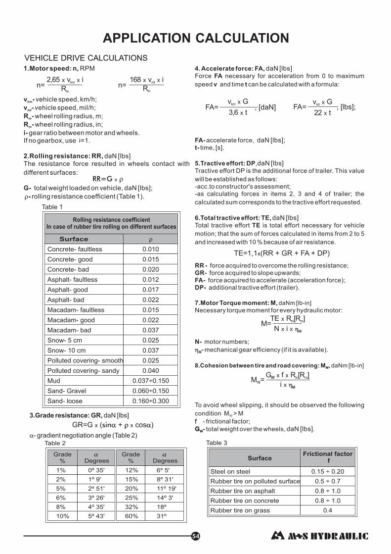
VEHICLE DRIVE CALCULATIONS
54
4. Accelerate force: FA,
FA
v t
t-
5.Tractive effort: DP
6.Total tractive effort: TE,
TE
RR -
GR-
FA-
DP-
7.Motor Torque moment: M,
N-
Force necessary for acceleration from 0 to maximum
speed and time can be calculated with a formula:
time, [s].
,
Tractive effort DP is the additional force of trailer. This value
will be established as follows:
-acc.to constructor's assessment;
-as calculating forces in items 2, 3 and 4 of trailer; the
calculated sum corresponds to the tractive effort requested.
Total tractive effort is total effort necessary for vehicle
motion; that the sum of forces calculated in items from 2 to 5
and increased with 10 % because of air resistance.
force acquired to overcome the rolling resistance;
force acquired to slope upwards;
force acquired to accelerate (acceleration force);
additional tractive effort (trailer).
Necessary torque moment for every hydraulic motor:
motor numbers;
mechanical gear efficiency (if it is available).
To avoid wheel slipping, it should be observed the following
condition M > M
- frictional factor;
total weight over the wheels, .
daN [lbs]
daN [lbs]
daN [lbs]
daN [lbs]
daN [lbs]
FA- accelerate force, ;
daNm [ ]
daNm -
�M-
f
-
8.Cohesion between tire and road covering: M , [ ]W
W
GW
lb-in
lb in
�M-
f
-
W
GW
1.Motor speed: n,
v -
R -
i-
2.Rolling resistance: RR,
-
RPM
vehicle speed, km/h;
wheel rolling radius, m;
gear ratio between motor and wheels.
If no gearbox, use i=1.
[ ]
The resistance force resulted in wheels contact with
different surfaces:
rolling resistance coefficient (Table 1).
km
m
v -
R -
G-
ml
in
vehicle speed, mil/h;
wheel rolling radius, in;
daN lbs
total weight loaded on vehicle, daN [lbs];
�
RR=G x �
Table 1
Concrete- faultless
Concrete- good
Concrete- bad
Asphalt- faultless
Asphalt- good
Asphalt- bad
Macadam- faultless
Macadam- good
Macadam- bad
Snow- 5 cm
Snow- 10 cm
Polluted covering- smooth
Polluted covering- sandy
Mud
Sand- Gravel
Sand- loose
0.010
0.015
0.020
0.012
0.017
0.022
0.015
0.022
0.037
0.025
0.037
0.025
0.040
0.037÷0.150
0.060÷0.150
0.160÷0.300
Surface
Rolling resistance coefficient
In case of rubber tire rolling on different surfaces
�
TE=1,1 (RR + GR + FA + DP)x
M=
M =W
Table 3
0.15 ÷ 0.20
0.5 ÷ 0.7
0.8 ÷ 1.0
0.8 ÷ 1.0
0.4
Frictional factor
f
Steel on steel
Rubber tire on polluted surface
Rubber tire on asphalt
Rubber tire on concrete
Rubber tire on grass
Surface
3.Grade resistance: GR,
- gradient negotiation angle (Table 2)
daN [lbs]
�
1%
2
5
6
8
10
%
%
%
%
%
12
15
20
25
32
60%
%
%
%
%
%
Table 2
Degrees Degrees
0º 35'
1º 9'
2º 51'
3º 26'
4º 35'
5º 43'
6º 5'
8º 31'
11º 19'
14º 3'
18º
31º
Grade%
Grade%
FA= , ;[lbs]v G
22
ml x
txFA= , [daN]
v G
3,6
km x
tx
n=2,65 v i
R
x xkm
m
n=168 v i
R
x xml
in
APPLICATION CALCULATION

MOTORS
HYDRAULIC
9.Radial motor loading: P
P
, [ ]
When motor is used for vehicle motion with wheels
mounted directly on motor shaft, the total radial
loading of motor shaft is a sum of motion force and
weight force acting on one wheel.
rad
rad
daN lbs
M
R
Prad
GW
P = G +rad
M
R
2
W
2
G -W Weight held by wheel;
P -
M/R-
rad Total radial loading of motor shaft;
Motion force.
In accordance with calculated loadings the suitable motor from the catalogue is selected.
DRAINAGE SPACE AND DRAINAGE PRESSURE
Advantages in oil drainage from drain space: Cleaning; Cooling and Seal lifetime prolonging.
Parallel connection
Series connection
55
M+S Hydraulic warrants, what its products, supplied directly to original equipmentmanufacturer, authorized distributor or other customer, will be free of defects in material orworkmanship at the time of shipment from M+S Hydraulic and will conform to the productstechnical documentation (drawings and specifications) under sale agreement with Buyer.
This warranty will apply only to defects appearing within applicable Warranty period,mentioned below. If Buyer notify M+S Hydraulic within the Warranty period about any suchdefects, M+S , at its sole option will replace or repair the defective products or their partsfound by M+S Hydraulic to be defective in material or workmanship.
THE FOREGOING LIMITED WARRANTY ISAVAILABLE ONLY IF “M+S HYDRAULIC”IS PROMPTLY NOTIFIED IN WRITING OF THE ALLEGED DEFECT AND DOES NOTCOVER FAILURE TO FUNCTION CAUSED BY DAMAGE TO THE PRODUCT,IMPROPER INSTALLATION, UNREASONABLE USE OR ABUSE OF THE PRODUCT,FAILURE TO PROVIDE OR USE OF IMPROPER MAINTENANCE OR USUAL,DEGRADATION OF THE PRODUCT DUE TO PHYSICAL ENVIRONMENTS OF ANUSUAL NATURE. THE FOREGOING REMEDIES ARE THE SOLE AND EXCLUSIVEREMEDIES AVAILABLE TO CUSTOMER. To facilitate the inspection, M+S Hydraulic mayrequire return of the product/part, which Buyer claims to be defective.
M+S Hydraulic shall not be liable for labor costs or any other expenses incurred duringthe disassembling or reinstalling of the product/part.
In case the claimed products are returned to M+S Hydraulic in bad condition: dirty,disassembled, with damaged or missing parts during transportation, the warranty will beconsidered as not applicable and the products will not be liable to repair.
The Warranty period is limited to 24 consecutive months (2 years) fromthe date of production of the product.
If the product is repaired in M+S Hydraulic during its warrantyperiod, the warranty period of the repaired item shall continue for the balance of originalWarranty period or for a period equal to 50% of the original new product Warranty period,whichever is later.
The Warranty period for Spare parts shall be 12 consecutive months (1year) from the dispatch date of such parts from M+S Hydraulic.
LIMITATION OF LIABILITY M+S Hydraulic's liability for any claim of any kind , for anyloss or damage arising out of, connected with or resulting from an order, or from theperformance or branch thereof, or from the design, manufacture, sale delivery, operationor use of any of its products shall be limited to , at M+S 's sole option, replacement, repair ofany defective product or the issuance of a credit to Customer against any futurepurchases. Cash refunds will not be made under any circumstances and Customer will notbe entitled to recover any damages of any kind against M+S Hydraulic, including but notlimited to incidental or consequential damages, whether direct or indirect, known orunknown, foreseen or unforeseen.
Warranty periods
New products:
Repaired products:
Spare parts:
WARRANTY