Hydraulic Motors, Fixed - parker.czm... · 7-8- 4 Parker Hannifin Corporation Hydraulics Group...
52
aerospace climate control electromechanical filtration fluid & gas handling hydraulics pneumatics process control sealing & shielding Hydraulic Motor Series F11/F12 Fixed Displacement
Transcript of Hydraulic Motors, Fixed - parker.czm... · 7-8- 4 Parker Hannifin Corporation Hydraulics Group...
aerospaceclimate controlelectromechanicalfiltrationfluid & gas handlinghydraulicspneumaticsprocess controlsealing & shielding
Hydraulic MotorSeries F11/F12 Fixed Displacement

7-8- 2 Parker Hannifin CorporationHydraulics Group
Hydraulic Motors, FixedSeries F11/F12
Catalogue HY02-8001/UK
Catalogue HY30-8249/UK. 11/2009
Conversion factors1 kg ................................................................. 2.20 lb1 N ............................................................... 0.225 lbf1 Nm ......................................................... 0.738 lbf ft1 bar ..............................................................14.5 psi1 l ......................................................0.264 US gallon1 cm3 .......................................................0.061 cu in1 mm ............................................................. 0.039 in9/5°C + 32 ............................................................1°F1 kW .............................................................. 1.34 hp
Torque (M)
M = [Nm]
Basic formulas for hydraulic motors
Flow (q)
q = [l/min]
Power (P)
P = [kW]
D x n 1000 x ηv
D x ∆p x ηhm 63
q x ∆p x ηt
600
D - displacement [cm3/rev] n - shaft speed [rpm] ηv - volumetric efficiency ∆p - differential pressure [bar] (between inlet and outlet)ηhm - mechanical efficiency ηt - overall efficiency (ηt = ηv x ηhm)

7-8- 3 Parker Hannifin CorporationHydraulics Group
Hydraulic Motors, FixedSeries F11/F12
Catalogue HY02-8001/UK
7
Content
Content Page 7-8-General information ..............................................................................4F11 cross section .................................................................................4F12 cross sections ................................................................................5Specifications .......................................................................................6Ordering codesF11-CETOP ..........................................................................................7F11-ISO ................................................................................................8F11-SAE ...............................................................................................9F12-ISO ..............................................................................................10F12-Cartridge .....................................................................................11F12-SAE .............................................................................................12Preferred versions F11/F12 ................................................................13Technical informationBearing life ..........................................................................................14Efficiency ............................................................................................15Noise level ..........................................................................................15Installation dimensionsF11-5 CETOP .....................................................................................16F11-6, -10 CETOP ..............................................................................17F11-12 CETOP ...................................................................................18F11-14 CETOP ...................................................................................19F11-19 CETOP ...................................................................................20F11-10 ISO .........................................................................................21F11-12 ISO .........................................................................................22F11-14 ISO .........................................................................................23F11-10 SAE ........................................................................................24F11-12 SAE ........................................................................................25F11-14 SAE ........................................................................................26F11-19 SAE ........................................................................................27F12-30, -40, -60, -80, -90, -110 and -125 ISO ...................................28F12-30, -40, -60, -80, -90, -110 and -125 Cartridge ...........................30F12-30, -40, -60, -80, -90, -110 and -125 SAE with 4 bolt flange .......32F12-30, -40, and -60 SAE with 2 bolt flange .......................................34F12-150 CETOP .................................................................................36F12-150 SAE ......................................................................................37F12-250 SAE ......................................................................................38Technical informationF11 in saw motor applications ............................................................39Series F11iP .......................................................................................39F11 and F12 fan motors .....................................................................41Flushing valves for F12 motors ...........................................................42FV13 flushing valve block ..................................................................43SR pressure relief / make-up valve .....................................................44SP super shockless, pressure relief valve .........................................47Speed sensor .....................................................................................49Installation informationDirection of rotation ............................................................................50Hydraulic fluids ...................................................................................50Operating temperature .......................................................................50F11/F12 in series operation ...............................................................50Viscosity .............................................................................................51Filtration ..............................................................................................51Case pressure ....................................................................................51Case drain connections ......................................................................52Before start-up ....................................................................................52

7-8- 4 Parker Hannifin CorporationHydraulics Group
Hydraulic Motors, FixedSeries F11/F12
Catalogue HY02-8001/UK
F11 cross section
1. Barrel housing
2. Valve plate
3. Cylinder barrel
4. Guide spacer with O-rings
5. Timing gear
6. Roller bearing
7. Bearing housing
8. Shaft seal
9. Output/input shaft
10. Piston with laminated piston ring
F11_section.epsLeif A./020204
10
1 2 3 4 5 6 7 8 9
F11 and F12 are bent axis, fixed displacement heavy-duty motor series. They can be used in numerous ap-plications in both open and closed loop circuits.• Series F11 is available in the following frame sizes
and versions: - F11-5, -6, -10, -12, -14 and -19 with
CETOP mounting flange and shaft end - F11-10, -12 and -14 with ISO flange and shaft - F11-10, -12, -14 and -19 with
SAE flange and shaft• Series F12 conforms to current ISO and SAE mounting
flange and shaft end configurations. A very compact cartridge version is also available.
• Thanks to the unique spherical piston design, F11/F12 motors can be used at unusually high shaft speeds. Operating pressures to 480 bar provides for the high output power capability.
• The 40° angle between shaft and cylinder barrel allows for a very compact, lightweight motor.
• The laminated piston ring offers important advantages such as low internal leakage and thermal shock resist-ance.
• The F11/F12 motors produce very high torque at start-up as well as at low speeds.
• Our unique timing gear design synchronizes shaft and cylinder barrel, making the F11/F12 very tolerant to high 'G' forces and torsional vibrations.
• Heavy duty roller bearings permit substantial external axial and radial shaft loads.
• The F11's and F12's have a simple and straight-for-ward design with very few moving parts, making them very reliable motors.
• The unique piston locking, timing gear and bearing set-up as well as the limited number of parts add up to a very robust design with long service life and, above all, proven reliability.
General information
7-8- 5 Parker Hannifin CorporationHydraulics Group
Hydraulic Motors, FixedSeries F11/F12
Catalogue HY02-8001/UK
7
F12_60_section.epsLeif A./020204
1 2 3 4 5 6 7 8 9
F12_110_section.epsLeif A./020204
1 2 3 10 4 5 6 7 8 9
11
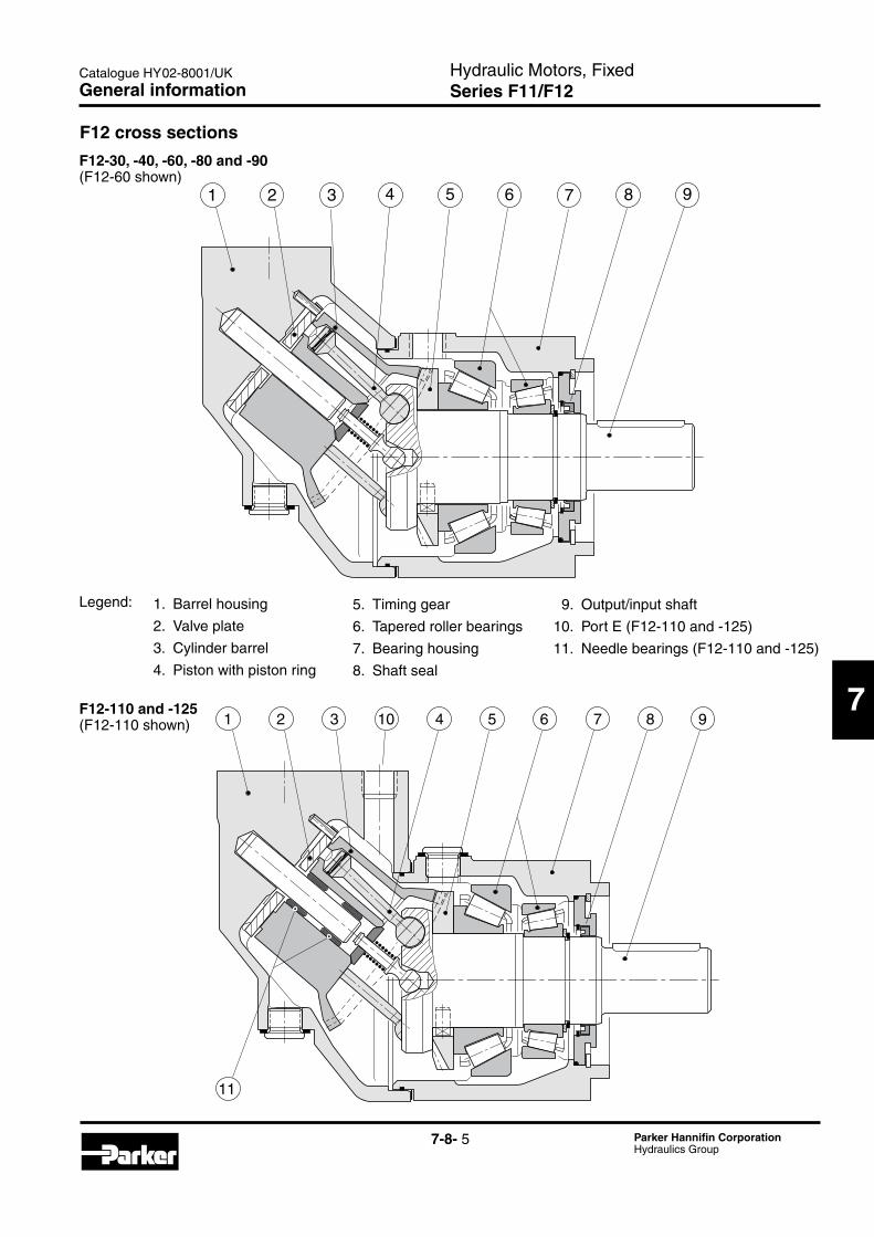
F12 cross sections
1. Barrel housing
2. Valve plate
3. Cylinder barrel
4. Piston with piston ring
F12-30, -40, -60, -80 and -90(F12-60 shown)
5. Timing gear
6. Tapered roller bearings
7. Bearing housing
8. Shaft seal
9. Output/input shaft
10. Port E (F12-110 and -125)
11. Needle bearings (F12-110 and -125)
F12-110 and -125(F12-110 shown)
Legend:
General information

7-8- 6 Parker Hannifin CorporationHydraulics Group
Hydraulic Motors, FixedSeries F11/F12
Catalogue HY02-8001/UK
Frame size F11 -5 -6 -10 -12 -14 -19
Displacement [cm3/rev] 4.9 6.0 9.8 12.5 14.3 19.0
Operating pressure max intermittent1) [bar] 420 420 max continuous [bar] 350 350
Motor operating speed [rpm] max intermittent1) 14 000 11 200 11 200 10 300 9 900 8 900 max continuous 12 800 10 200 10 200 9 400 9 000 8 100 min continuous 50 50
Motor input flow max intermittent1) [l/min] 69 67 110 129 142 169 max continuous [l/min] 63 61 100 118 129 154
Main circuit temp.3), max [°C] 80 80 min [°C] -40 -40
Theoretical torque at 100 bar [Nm] 7.8 9.5 15.6 19.8 22.7 30.2
Mass moment of inertia (x10-3) [kg m2] 0.16 0.39 0.39 0.40 0.42 1.1
Weight [kg] 4.7 7.5 7.5 8.2 8.3 11
Frame size F12 -30 -40 -60 -80 -90 -110 -125 -150 -250
Displacement [cm3/rev] 30.0 40.0 59.8 80.4 93.0 110.1 125.0 150 242
Operating pressure max intermittent1) [bar] 480 480 420 480 480 420 420 max continuous [bar] 420 420 350 420 420 350 350
Motor operating speed [rpm] max intermittent1) 7 300 6 700 5 800 5 300 5 000 4 800 4 600 3 500 3 000 max continuous 6 700 6 100 5 300 4 800 4 600 4 400 4 200 3 200 2 700 min continuous 50 50
Motor input flow max intermittent1) [l/min] 219 268 347 426 465 528 575 525 726 max continuous [l/min] 201 244 317 386 428 484 525 480 653
Main circuit temp.3), max [°C] 80 80 min [°C] -40 -40
Theoretical torque at 100 bar [Nm] 47.6 63.5 94.9 127.6 147.6 174.8 198.4 238.1 384.1
Mass moment of inertia (x10-3) [kg m2] 1.7 2.9 5 8.4 8.4 11.2 11.2 40 46
Weight [kg] 12 16.5 21 26 26 36 36 70 77
1) Intermittent: max 6 seconds in any one minute. 3) See also installation information, operating temperature.
Specifications

7-8- 7 Parker Hannifin CorporationHydraulics Group
Hydraulic Motors, FixedSeries F11/F12
Catalogue HY02-8001/UK
7
Frame size 5 6 10 12 14 19 Code Function M Motor x x x - - x H Motor, high pressure x - x x x x S Motor, high speed - - (x) - - (x)
For other versions, contact Parker Hannifin
Frame sizeCode Displacem. (cm3/rev) 005 4.9 006 6.0 010 9.8 012 12.5 014 14.3 019 19.0
F11-CETOP
x: Available (x): Optional – : Not available 1) NBR - Nitrile rubber2) FPM - Fluor rubber3) Special version number 349
Ordering codes
Frame size 5 6 10 12 14 19Code Main ports B BSP threads x x x x x x U SAE, UN threads (x) - (x) - - (x)
Frame size 5 6 10 12 14 19Code Mounting flange C CETOP flange x x x x x x W Saw motor flange - - (x) (x) (x) (x)
Frame size 5 6 10 12 14 19Code Shaft seal N NBR1), low pressure (x) (x) (x) - - (x) V FPM2), high pressure, high temperature x x x x x x S FPM2), saw motor - (x) (x) - - (x)
Frame size 5 6 10 12 14 19Code Shaft K Metric key x x x x x x
K Metric key, 25 mm3) - (x) (x) (x) - -
D Spline, DIN 5480 (x) (x) (x) (x) (x) (x)
S Spline, SAE (x) - - - - -
Frame size 5 6 10 12 14 19Code Option MVR Make-up valve clockwise rotation - - (x) (x) (x) (x)
MVL Make-up valve counter clockwise rotation - - (x) (x) (x) (x)
Version number(assigned for special versions)
F11 — — —— — — —
Frame
size
Function Main
ports
Mounting
flange
Shaft
seal
Shaft Version
number
Option
page 41
Option
page 49
Frame size 5 6 10 12 14 19Code Option P Prepared for speed sensor - - - (x) (x) (x)

7-8- 8 Parker Hannifin CorporationHydraulics Group
Hydraulic Motors, FixedSeries F11/F12
Catalogue HY02-8001/UK
F11-ISO
x: Available (x): Optional – : Not available 1) FPM - Fluor rubber2) Special version number 349
Ordering codes
Frame sizeCode Displacem. (cm3/rev) 010 9.8 012 12.5 014 14.3
Frame size 10 12 14Code Main ports F Metric threads x x x B BSP threads (x) (x) (x)
Frame size 10 12 14 Code Function M Motor x - - H Motor, high pressure x x x S Motor, high speed (x) - -
Frame size 10 12 14Code Mounting flange I ISO flange x x x
Frame size 10 12 14Code Shaft seal V FPM1), high pressure, high temperature x x x S FPM1), saw motor (x) - -
Version number(assigned for special versions)
F11 — — —— — — —
Frame
size
Function Main
ports
Mounting
flange
Shaft
seal
Shaft Version
number
Option
page 41
Option
page 49
Frame size 10 12 14Code Option P Prepared for speed sensor - (x) (x)
Frame size 10 12 14Code Shaft K Metric key x x x
D Spline, DIN 5480 (x) (x) (x)
K Metric key, 25 mm2) (x) (x) -
Frame size 10 12 14Code Option MVR Make-up valve clockwise rotation (x) (x) (x)
MVL Make-up valve counter clockwise rotation (x) (x) (x)

7-8- 9 Parker Hannifin CorporationHydraulics Group
Hydraulic Motors, FixedSeries F11/F12
Catalogue HY02-8001/UK
7
Ordering codes
F11-SAE
x: Available (x): Optional – : Not available 1) NBR - Nitrile rubber2) FPM - Fluor rubber3) Special version number 349
Frame sizeCode Displacem. (cm3/rev) 010 9.8 012 12.5 014 14.3 019 19.0
Frame size 10 12 14 19Code Main ports U SAE, UN threads x x x x B BSP threads (x) (x) - (x)
Frame size 10 12 14 19Code Function M Motor x - - x H Motor, high pressure x x x x S Motor, high speed (x) - - (x)
For other versions, contact Parker Hannifin
Frame size 10 12 14 19Code Mounting flange S SAE flange x x x x
Frame size 10 12 14 19Code Shaft seal N NBR1), low pressure (x) - - (x) V FPM2), high pressure, high temperature x x x x S FPM2), saw motor (x) - - (x)
Version number(assigned for special versions)
F11 — — —— — — —
Frame
size
Function Main
ports
Mounting
flange
Shaft
seal
Shaft Version
number
Option
page 41
Option
page 49
Frame size 10 12 14 19Code Shaft T SAE key - - x x S SAE spline (x) (x) (x) (x) K Metric key x x - - K Metric key, 25 mm3) (x) (x) - -
Frame size 10 12 14 19Code Option MVR Make-up valve clockwise rotation (x) (x) (x) (x)
MVL Make-up valve counter clockwise rotation (x) (x) (x) (x)
Frame size 10 12 14 19Code Option P Prepared for speed sensor - (x) (x) (x)

7-8- 10 Parker Hannifin CorporationHydraulics Group
Hydraulic Motors, FixedSeries F11/F12
Catalogue HY02-8001/UKOrdering codes
F12-ISO
Frame sizeCode Displacem. (cm3/rev) 030 30.0 040 40.0 060 59.8 080 80.4 090 93.0 110 110.1 125 125.0
Frame size 30 40 60 80 90 110 125Code Option P Prepared for speed sensor (x) (x) (x) (x) (x) (x) (x)
Frame size 30 40 60 80 90 110 125Code Main ports F SAE 6000 psi flange x x x x x x x
Frame size 30 40 60 80 90 110 125Code Shaft seal N NBR1), low pressure (x) (x) (x) (x) (x) (x) (x) V FPM2), high temperature, x x x x x x x high pressure
Frame size 30 40 60 80 90 110 125Code Shaft D DIN spline Optional (x) (x) (x) (x) (x) (x) (x) Z " " Optional (x) (x) (x) (x) (x) (x) (x) K Metric key Standard x x x x x x x P " " Optional (x) - - - - - -
Frame size 30 40 60 80 90 110 125Code Option L01 Integr. flushing valve (x) (x) (x) (x) (x) -3) -3)
MVR Make-up valve clockwise rotation (x) - - - - - -
MVL Make-up valve counter clockwise rotation (x) - - - - - -
Frame size 30 40 60 80 90 110 125Code Mounting flange I ISO flange x x x x x x x
Frame size 30 40 60 80 90 110 125Code Function M Motor x x x x x x x
x : Available (x): Optional – : Not available1) NBR - Nitrile rubber2) FPM - Fluor rubber3) F12-110 and -125: Accessory valve block (page 43)
Version number (assigned for special versions)
F12 — — —— — — —
Frame
size
Function Main
ports
Mounting
flange
Shaft
seal
Shaft Version
number
Option
page 41-42
Option
page 49

7-8- 11 Parker Hannifin CorporationHydraulics Group
Hydraulic Motors, FixedSeries F11/F12
Catalogue HY02-8001/UK
7
F12-Cartridge CETOP
Ordering codes
F12 — — —— — — —
Frame
size
Function Main
ports
Mounting
flange
Shaft
seal
Shaft Version
number
Option
page 41-42
Option
page 49
Frame size 30 40 60 80 90 110 125 150Code Function M Motor x x x x x x x x
H Motor, high pressure - - - - - - - (x)
Frame size 30 40 60 80 90 110 125 150Code Shaft C DIN spline Standard x x x x x x x -
K Metric key Optional (x) - (x) (x) (x) - - x
X Metric key4) Optional - (x) - - - - - -
X Spline 5) DIN 5480 - - - - - x x -
D Spline DIN 5480 - - - - - - - (x)
x : Available (x): Optional – : Not available1) NBR - Nitrile rubber2) FPM - Fluor rubber3) F12-110 and -125: Accessory valve block (page 43)4) Special version number 2645) Special version number 326
Version number (assigned for special versions)
Frame size 30 40 60 80 90 110 125 150Code Main ports F SAE 6000 psi flange x x x x x x x x
Frame size 30 40 60 80 90 110 125 150Code Mounting flange C Cartridge x x x x x x x -
C CETOP - - - - - - - x
Frame size 30 40 60 80 90 110 125 150Code Option P Prepared for speed sensor x (x) (x) (x) (x) x x -
Frame size 30 40 60 80 90 110 125 150Code Shaft seal N NBR1), low pressure (x) (x) (x) (x) (x) (x) (x) (x) V FPM2), high temperature, x x x x x x x x high pressure
Frame size 30 40 60 80 90 110 125 150Code Option L01 Integr. flushing valve (x) (x) (x) (x) (x) -3) -3) -
MVR Make-up valve clockwise rotation (x) - - - - - - -
MVL Make-up valve counter clockwise rotation (x) - - - - - - -
Frame sizeCode Displacem. (cm3/rev) 030 30.0 040 40.0 060 59.8 080 80.4 090 93.0 110 110.1 125 125.0 150 150.0

7-8- 12 Parker Hannifin CorporationHydraulics Group
Hydraulic Motors, FixedSeries F11/F12
Catalogue HY02-8001/UK
x : Available (x): Optional – : Not available1) NBR - Nitrile rubber2) FPM - Fluor rubber3) F12-110 and -125: Accessory valve block (page 43)4) Metric threads
Ordering codes
F12 — — —— — — —
F12-SAE Frame
size
Function Main
ports
Mounting
flange
Shaft
seal
Shaft Version
number
Option
page 41-42
Option
page 49
Frame size 30 40 60 80 90 110 125 150 250Code Main ports S SAE 6000 psi flange x x x x x x x - -
U SAE, UN threads (x) (x) (x) (x) (x) (x) (x) - -
F SAE 6000 psi flange4) - - - - - - - x x
Frame size 30 40 60 80 90 110 125 150 250Code Shaft S SAE spline Optional (x) (x) (x) (x) (x) (x) (x) (x) (x) U " " Optional - - - (x) (x) - - - - T SAE key Standard x x x x x x x x - K Metric key - - - - - - - (x) x F SAE spline - - - - - - - - (x) D Spline, DIN 5480 - - - - - - - - (x)
Frame size 30 40 60 80 90 110 125 150 250Code Mounting flange S SAE 4 bolt x x x x x x x x x
T SAE 2 bolt x x x - - - - - -
Frame size 30 40 60 80 90 110 125 150 250Code Function M Motor x x x x x x x x -
H Motor, high pressure - - - - - - - (x) -
Q Motor - - - - - - - - x
Version number (assigned for special versions)
Frame size 30 40 60 80 90 110 125 150 250Code Option P Prepared for speed sensor (x) (x) (x) (x) (x) (x) (x) - -
Frame size 30 40 60 80 90 110 125 150 250Code Shaft seal N NBR1), low pressure (x) (x) (x) (x) (x) (x) (x) (x) - V FPM2), high temperature, x x x x x x x x x high pressure
Frame size 30 40 60 80 90 110 125 150 250Code Option L01 Integr. flushing valve (x) (x) (x) (x) (x) -3) -3) - - MVR Make-up valve clockwise rotation (x) - - - - - - - - MVL Make-up valve counter clockwise rotation (x) - - - - - - - -
Frame sizeCode Displacem. (cm3/rev) 030 30.0 040 40.0 060 59.8 080 80.4 090 93.0 110 110.1 125 125.0 150 150.0 250 242.0
7-8- 13 Parker Hannifin CorporationHydraulics Group
Hydraulic Motors, FixedSeries F11/F12
Catalogue HY02-8001/UK
7
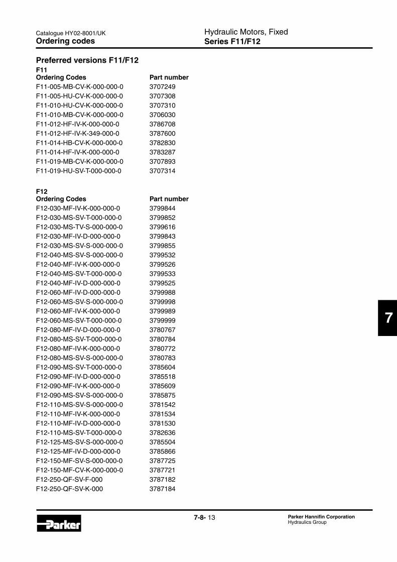
Preferred versions F11/F12F11Ordering Codes Part numberF11-005-MB-CV-K-000-000-0 3707249F11-005-HU-CV-K-000-000-0 3707308F11-010-HU-CV-K-000-000-0 3707310F11-010-MB-CV-K-000-000-0 3706030F11-012-HF-IV-K-000-000-0 3786708F11-012-HF-IV-K-349-000-0 3787600F11-014-HB-CV-K-000-000-0 3782830F11-014-HF-IV-K-000-000-0 3783287F11-019-MB-CV-K-000-000-0 3707893F11-019-HU-SV-T-000-000-0 3707314
F12Ordering Codes Part numberF12-030-MF-IV-K-000-000-0 3799844F12-030-MS-SV-T-000-000-0 3799852F12-030-MS-TV-S-000-000-0 3799616F12-030-MF-IV-D-000-000-0 3799843F12-030-MS-SV-S-000-000-0 3799855F12-040-MS-SV-S-000-000-0 3799532F12-040-MF-IV-K-000-000-0 3799526F12-040-MS-SV-T-000-000-0 3799533F12-040-MF-IV-D-000-000-0 3799525F12-060-MF-IV-D-000-000-0 3799988F12-060-MS-SV-S-000-000-0 3799998F12-060-MF-IV-K-000-000-0 3799989F12-060-MS-SV-T-000-000-0 3799999F12-080-MF-IV-D-000-000-0 3780767F12-080-MS-SV-T-000-000-0 3780784F12-080-MF-IV-K-000-000-0 3780772F12-080-MS-SV-S-000-000-0 3780783F12-090-MS-SV-T-000-000-0 3785604F12-090-MF-IV-D-000-000-0 3785518F12-090-MF-IV-K-000-000-0 3785609F12-090-MS-SV-S-000-000-0 3785875F12-110-MS-SV-S-000-000-0 3781542F12-110-MF-IV-K-000-000-0 3781534F12-110-MF-IV-D-000-000-0 3781530F12-110-MS-SV-T-000-000-0 3782636F12-125-MS-SV-S-000-000-0 3785504F12-125-MF-IV-D-000-000-0 3785866F12-150-MF-SV-S-000-000-0 3787725F12-150-MF-CV-K-000-000-0 3787721F12-250-QF-SV-F-000 3787182F12-250-QF-SV-K-000 3787184
Ordering codes

7-8- 14 Parker Hannifin CorporationHydraulics Group
Hydraulic Motors, FixedSeries F11/F12
Catalogue HY02-8001/UK
F12_shaft_loads.EPSLeif A./020204
F α F
Bearing_life_DE.epsLeif A./020201
Life expectancy (logarithmic scale)
Other causes
Bearing fatigue
Rotating group fatigue and wear
System pressure
Hydraulicunitlifeversussystempressure.
Bearing life
General informationBearing life can be calculated for that part of the load/life curve (shown below) that is designated 'Bearing fatigue'. 'Rotating group fatigue and wear' and 'Other' caused by material fatigue, fluid contamination, etc. should also be taken into consideration when estimat-ing the service life of a motor in a specific application.Bearing life calculations are mainly used when compar-ing different frame sizes. Bearing life, designated B10 (or L10), is dependent of system pressure, operating speed, external shaft loads, fluid viscosity in the case, and fluid contamination level.The B10 value means that 90% of the bearings survive, at a minimum, the number of hours calculated. Statisti-cally, 50% of the bearings will survive at least five times the B10 life.
Required informationWhen requesting a bearing life calculation from Parker Hannifin, the following information (where applicable) should be provided:- A short presentation of the application- F11 or F12 size and version- Duty cycle (pressure and speed versus time at given displacements)- Low system pressure- Case fluid viscosity- Life probability (B10, B20, etc.)- Operating mode (pump or motor)- Direction of rotation (L or R)- External shaft loads (Forces, Gear, Belt, Cardan or none)For forces please provide: - Axial load, Fixed radial load, Bending moment, Ro-
tating radial load and distance flange to radial load. For Gear please provide: - Pitch diameter, Pressure angle, Spiral angle, Dis-
tance flange – gearwheel (mid) and Gearwheel spiral direction (R or L).
For Belt please provide: - Pretension, Coefficient of friction, Angle of contact,
Distance flange – pulley (mid) and Diameter pulley. For Cardan please provide: - Shaft angle, Distance flange – first joint and dis-
tance between joints - Angle of attack (α) as defined below
The direction (a) of the radial load is positive in the direction of rotation as shown.To obtain maximum bearing life, the radial load should, in most cases, be located approximately at 170° (motor; R.H. rot'n).
Technical information
Bearing life calculationAn application is usually governed by a certain duty or work cycle where pressure and speed vary with time during the cycle.In addition, bearing life depends on external shaft forc-es, fluid viscosity in the case and fluid conta-mination.Parker Hannifin has a computer program for calculating bearing life and will assist in determining F11 or F12 motor life in a specific application.
7-8- 15 Parker Hannifin CorporationHydraulics Group
Hydraulic Motors, FixedSeries F11/F12
Catalogue HY02-8001/UK
7
Efficiency_F12_DE.epsLeif A./020201
100%
90%
80%
0 1000 2000 3000 4000
100%
90%
80%
0 1000 2000 3000 4000
F12-30
F12-30
210 bar
420 bar
420 bar
210 bar
Speed [rpm]Volymetricefficiency.
Speed [rpm]Mechanicalefficiency.
(motor)
(motor)
90
85
80
75
70
65
0 100 200 300
Noise_F12.epsLeif A./020204
Noise level [dB(A)]
5000 rpm
3500 rpm
2000 rpm
Pressure [bar]
F12-30 (M function )
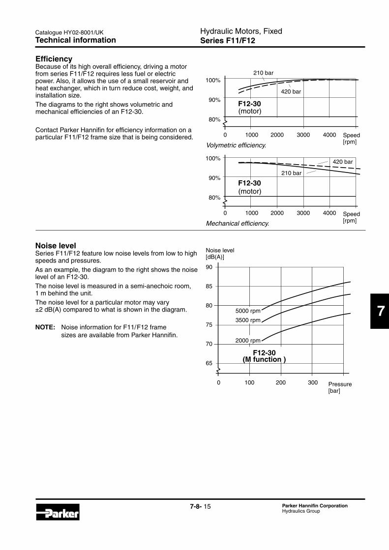
Noise levelSeries F11/F12 feature low noise levels from low to high speeds and pressures. As an example, the diagram to the right shows the noise level of an F12-30.The noise level is measured in a semi-anechoic room, 1 m behind the unit.The noise level for a particular motor may vary ±2 dB(A) compared to what is shown in the diagram.
NOTE: Noise information for F11/F12 frame sizes are available from Parker Hannifin.
EfficiencyBecause of its high overall efficiency, driving a motor from series F11/F12 requires less fuel or electric power. Also, it allows the use of a small reservoir and heat exchanger, which in turn reduce cost, weight, and installation size.The diagrams to the right shows volumetric and mechanical efficiencies of an F12-30.
Contact Parker Hannifin for efficiency information on a particular F11/F12 frame size that is being considered.
Technical information

7-8- 16 Parker Hannifin CorporationHydraulics Group
Hydraulic Motors, FixedSeries F11/F12
Catalogue HY02-8001/UK
F11-5(CETOP versions)
Installation dimensions
84 max
38
65
5
54
40
5
40°
9
13
134 max
96 max
53
8
25
9
20
M6x12 min
Ø127 max
Ø11 (x2)
100
W18x1,25x13x9g
F11_5_install.epsLeif A./031008
18
3528
Type C mounting flange
Flange C
Key 6x6x30
Type K key shaft
Approx. center of gravity
Type D spline shaft (DIN 5480)
Type S spline shaft (13T16/32 DP)
47.5
88.5
113.5
20.5
Ø80 (+0/-0.046)
Ø18 (+0.008/-0.003)
Ø20.3
Ø21.81
R 0.5R 0.7
Drain port C(BSP1/4")
Drain port C9/16"-18 UNFO-ring boss;SAE J514d
Main port A(BSP 1/2")
Main port A3/4"-16 UNFO-ring boss;SAE J514d
Main port B(BSP 1/2")
Main port B3/4"-16 UNFO-ring boss;SAE J514d
Drain port D(BSP1/4")
Main ports Code U

7-8- 17 Parker Hannifin CorporationHydraulics Group
Hydraulic Motors, FixedSeries F11/F12
Catalogue HY02-8001/UK
7
F11-6, -10(CETOP versions)
Installation dimensions
94 max
46
79
11 53
101
63
50
7
40°
9
14
156 max
Ø23min
116 max
57
133
8
30
9
22
42
M6x12 min
Ø152 max
Ø13 (x2)
125
W20x1,25x14x9g
F11_10_install.epsLeif A./031009
28
M10x16 min
Type C mounting flange
Flange C
Key 6x6x35
Type K key shaft
Approx. center of gravity
Type D spline shaft (DIN 5480)
22.5
R 0.5R 0.7
Drain port C(BSP3/8")
Main port A(BSP 3/4")
Main port B(BSP 3/4")
Drain port D(BSP3/8")
Ø20 (+0.009/-0.004)
Ø100 (+0/-0.054)
Ø25 (+0.005/-0.004)Type K key shaft
Key 8x7x353.5

7-8- 18 Parker Hannifin CorporationHydraulics Group
Hydraulic Motors, FixedSeries F11/F12
Catalogue HY02-8001/UK
F11-12(CETOP versions)
Installation dimensions
AB
F11_012_CETOP_ny.ai378 5935Leif A./06-08-11
(59)
116max
Ø13 (x2)
125
152 max
CCW CW
40°(x4)
101
46
30
M6x12 min
102
(45)
25°
72
53 +0/-1
101
(149)
14 (x2)
(32)
156max 133
8
509
7
Ø23
9
2242
28
M10x16 min
Make-up valve (MVL or MVR optional; clockwise rotation shown)
Speed sensor (optional)
Main port A(BSP 3/4")
Flange C
Type K key shaft
Drain port D(BSP3/8")
Spline shaft DW20x1.25x14x9g;
DIN 5480
Ø20 (+0.009/-0.004)
Ø100 (+0/-0.054)
22.5
Main port B(BSP 3/4")
Key 6x6x35
Ø25 (+0.005/-0.004)Type K key shaft
Key 8x7x353.5
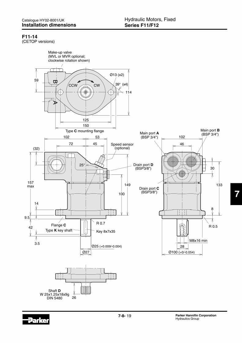
7-8- 19 Parker Hannifin CorporationHydraulics Group
Hydraulic Motors, FixedSeries F11/F12
Catalogue HY02-8001/UK
7
F11-14(CETOP versions)
Installation dimensions
F11_14_CETOP.epsLeif A./03-11-05
BA
25°
100
149157max
42
14
102
4572
53
(32)
59
125
Ø13 (x2)
114
150
39° (x4)
Ø27
102
46
30
8
28
M8x16 min
26
133
Speed sensor(optional)
CCW CW
Flange CType K key shaft
Shaft DW 25x1.25x18x9g
DIN 5480
Type C mounting flange
Key 8x7x35
Main port B(BSP 3/4")
Drain port C(BSP3/8")
Drain port D(BSP3/8")
Main port A(BSP 3/4")
R 0.5R 0.7
3.5
9.5
Ø25 (+0.009/-0.004)
Ø100 (+0/-0.054)
Make-up valve (MVL or MVR optional; clockwise rotation shown)

7-8- 20 Parker Hannifin CorporationHydraulics Group
Hydraulic Motors, FixedSeries F11/F12
Catalogue HY02-8001/UK
F11-19(CETOP version)
Installation dimensions
F11-19_CETOP_install.epsLeif A./020204
88
11
63 114 max
54
58
2542
165 max29
25
28
23
138
10016
10
45°
126
Ø172 max
Ø14 (x2)
87
140
M8x16 min
28
W25x1,25x18x9g
Type C mounting flange
Approx. center of gravity
Type K key shaft
Key 8x7x35
Type D spline shaft (DIN 5480)
Flange C
R 1.0max
R 1.2max3.5
Ø28.3min
Drain port C(BSP3/8")
Main port A(BSP 3/4") Main port B
(BSP 3/4")
Drain port D(BSP3/8")
Ø25 (+0.009/-0.004)Ø112 (+0/-0.054)
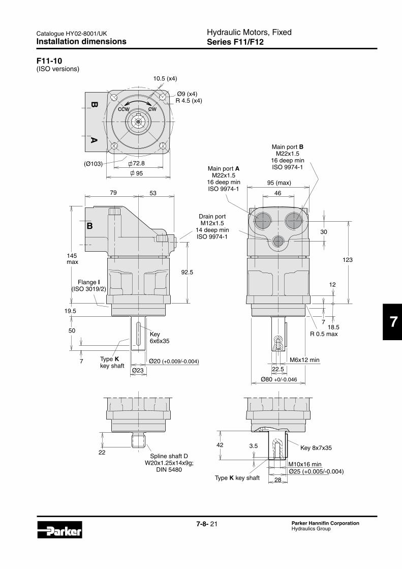
7-8- 21 Parker Hannifin CorporationHydraulics Group
Hydraulic Motors, FixedSeries F11/F12
Catalogue HY02-8001/UK
7
F11-10(ISO versions)
Installation dimensions
95
79 53
145max
95 (max)
46
30
12
123
7
M6x12 min
50
7
2242
Ø23
Ø9 (x4)
(Ø103)
F11_010_ISO_ny.ai378 3349Leif A./06-06-10
B
BA
ccw cw
28
M10x16 min
Main port AM22x1.5
16 deep minISO 9974-1
Flange I(ISO 3019/2)
Type K key shaft
Drain port M12x1.5
14 deep minISO 9974-1
Spline shaft DW20x1.25x14x9g;
DIN 5480
Ø20 (+0.009/-0.004)
Ø80 +0/-0.046
10.5 (x4)
Main port BM22x1.5
16 deep minISO 9974-1
19.5
22.5
18.5
3.5
92.5
72.8
R 0.5 max
R 4.5 (x4)
Key6x6x35
Type K key shaftØ25 (+0.005/-0.004)
Key 8x7x35

7-8- 22 Parker Hannifin CorporationHydraulics Group
Hydraulic Motors, FixedSeries F11/F12
Catalogue HY02-8001/UK
F11-12(ISO versions)
Installation dimensions
3.5
95
102 101
46
30
12
72
53
45
50
7Ø23
Ø9 (x4)
(Ø103)
F11_012_ISO_ny.ai378 5448Leif A./06-08-10
BA
ccw cw
90
139 123
147max
(59)
(32)
7
M6x12 min
28
M10x16 min
42
Speed sensor (optional)
Ø20 (+0.009/-0.004)
Ø80 +0/-0.046
Flange I(ISO 3019/2)
Type K key shaft
Main port AM26x1.5
16 deep minISO 9974-1
Drain portM16x1.5
12 deep minISO 9974-1
Main port BM26x1.5
16 deep minISO 9974-1
22.5
19.5
18.5
R 0.5
72.8
10.5 (x4)
R 4.5 (x4)
Key 6x6x35
Type K key shaftØ25 (+0.005/-0.004)
Key 8x7x35
Make-up valve (MVL or MVR optional; clockwise rotation shown)

7-8- 23 Parker Hannifin CorporationHydraulics Group
Hydraulic Motors, FixedSeries F11/F12
Catalogue HY02-8001/UK
7
F11-14(ISO versions)
Installation dimensions
F11_014_ISO.epsLeif A./03-10-03
BA
101
46
30
28
12
M8x16 min
Ø27
28
90
139147max
21
42
102
45
53
25°
Ø9 (x4)
(Ø103)
Ø9 (x4)
95
123
Speed sensor(optional)
Drain port D M16x1.5(depth 12; ISO 9974-1)
Flange I(ISO 3019/2)
Type K key shaft
CCW CW
Type I mounting flange (ISO 3019/2)
Key 8x7x35
W25x1.25x18x9gType D spline shaft
(DIN 5480)
Drain port C M16x1.5(depth 12; ISO 9974-1)
10.5 (x4)
3.5
R 0.5 max
6.7
18.5
Ø25 (+0.009/-0.004)
Ø80 (+0/-0.046)
72.8
Main port AM26x1.5
16 deep minISO 9974-1
Main port BM26x1.5
16 deep minISO 9974-1

7-8- 24 Parker Hannifin CorporationHydraulics Group
Hydraulic Motors, FixedSeries F11/F12
Catalogue HY02-8001/UK
F11-10(SAE versions)
Installation dimensions
F11_010_SAE_ny.ai378 5949Leif A./06-08-11
29° (x4) R60 (x2)
102
133
122 max
177 (max)146
CCW CWR14(x4)
79 53
Ø23
8
50
17(x2)
156 max
8
33
30
7
55
M6x12 min
23
94 max46
Main port A 11/16"-12 UNO-ring boss; SAE J514d
Drain port 9/16"-18 UNFO-ring boss; SAE J514d
Type K key shaft
Type S spline shaftSAE B, 13T, 16/32 DP(SAE J498b, class 1;30° involute spline;
flat root, side fit)
Main port B 11/16"-12 UNO-ring boss; SAE J514d
Ø20 (+0.009/-0.004)
Ø101.6 (+0/-0.05)
9.5
R 0.5
Ø14.4(x2)
Flange Ssize 101-2 SAE B
SAE J744c
22.5
Key 6x6x35

7-8- 25 Parker Hannifin CorporationHydraulics Group
Hydraulic Motors, FixedSeries F11/F12
Catalogue HY02-8001/UK
7
Installation dimensions
F11-12(SAE versions)
BA
F11_012_SAE_ny.aiLeif A./06-08-11
(58)
(32)
R 60 (x2)
146
174 max
R 14 (x4)
122
158 max
8
833
23
151
50
17 (x2)
7
Ø24 (x2)
102 53
72 45
Ø23
102
133
101
46
M6x12 min
30
Ø55
ccw cw29° (x4)
Type K key shaft
Flange Ssize 101-2 SAE B
SAE J744c
Drain port 9/16"-18 UNFO-ring boss; SAE J514d
Speed sensor (optional)
Type S spline shaftSAE B, 13T, 16/32 DP(SAE J498b, class 1;30° involute spline;
flat root, side fit)
Ø14.4(x2)
Ø20 (+0.009/-0.004)
Ø101.6 (+0/-0.05)
22.5
9.5
R 0.5
Key 6x6x35
Main port A 11/16"-12 UNO-ring boss; SAE J514d
Main port B 11/16"-12 UNO-ring boss; SAE J514d
Make-up valve (MVL or MVR optional; clockwise rotation shown)

7-8- 26 Parker Hannifin CorporationHydraulics Group
Hydraulic Motors, FixedSeries F11/F12
Catalogue HY02-8001/UK
F11-14(SAE versions)
Installation dimensions
F11_014_SAE.epsLeif A./03-10-03
101
46
30
Ø80
Ø24 (x2)
Ø27
102
24
33
8
151
17(x2)
158max
146
29° (x4)
102
45
53
25°
120
174 (max)
BA
R 14 (x4)
133
8
CCW CW
Speed sensor(optional)
Drain port D 9/16"-18 UNFO-ring boss; SAE J514d
Type T key shaftSize 25-1 (B–B)
(SAE J744c)
Type S spline shaftSAE B, 13T, 16/32 DP(SAE J498b, class 1;30° involute spline;
flat root, side fit)
5/16"-24 UNF-2B(depth 16)
Key 6.35x6.35x31.8
Type S mounting flange SAE 'B' ( SAE J744c)
Drain port C 9/16"-18 UNFO-ring boss; SAE J514d
Ø14.5 (x2)
9.5
R 0.538.1 2.3
Ø25.4 (+0/-0.05)
Ø101.6 (+0/-0.05)
28.1
Main port A 11/16"-12 UNO-ring boss; SAE J514d
Main port B 11/16"-12 UNO-ring boss; SAE J514d
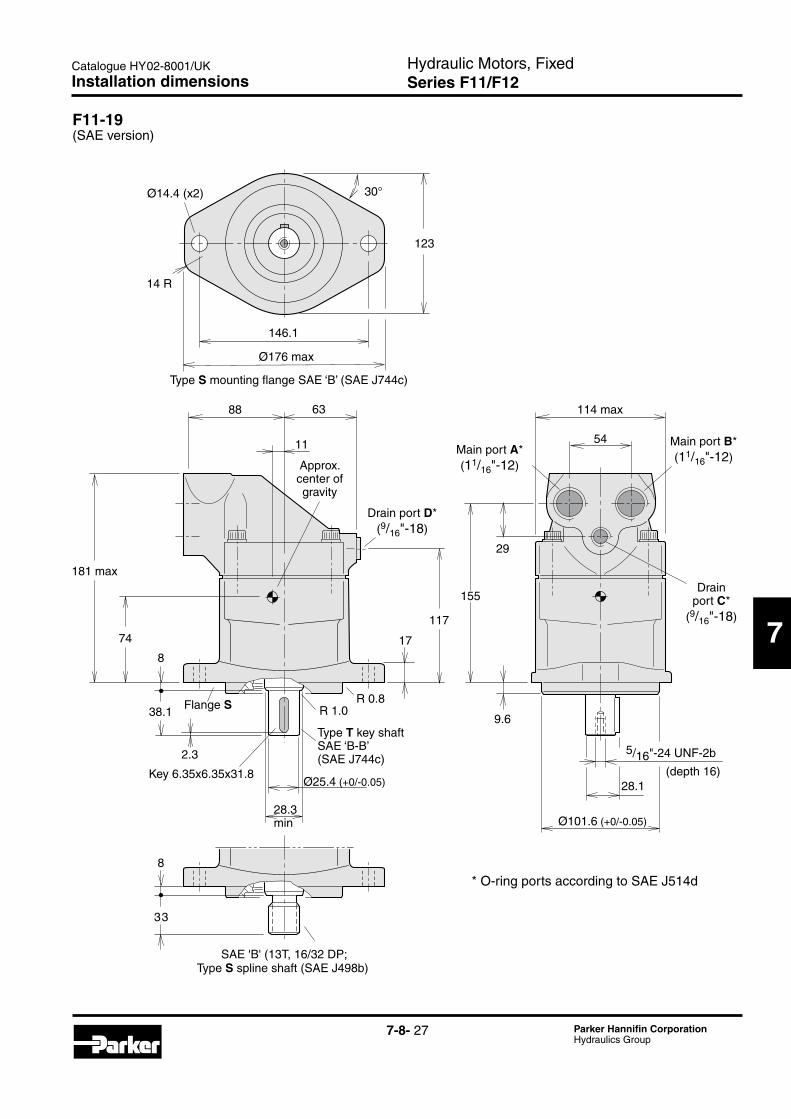
7-8- 27 Parker Hannifin CorporationHydraulics Group
Hydraulic Motors, FixedSeries F11/F12
Catalogue HY02-8001/UK
7
F11-19(SAE version)
Installation dimensions
F11_19_SAE_install.epsLeif A./020204
88
11
63
74
8
181 max
8
33
117
17
SAE 'B' (13T, 16/32 DP;class1, flat root, side fit)
54
Ø176 max
29
155
30°
5/16"-24 UNF-2b
14 R
123
114 max
Type S mounting flange SAE ‘B’ (SAE J744c)
Approx. center of gravity
Flange S
Type S spline shaft (SAE J498b)
Type T key shaftSAE ‘B-B’ (SAE J744c)
Ø14.4 (x2)
146.1
38.1
28.1(depth 16)
R 1.0R 0.8
* O-ring ports according to SAE J514d
9.6
Main port A*(11/16"-12)
Drain port D*(9/16"-18)
28.3min
Drain port C*
(9/16"-18)
Main port B*(11/16"-12)
Key 6.35x6.35x31.8Ø25.4 (+0/-0.05)
Ø101.6 (+0/-0.05)
2.3

7-8- 28 Parker Hannifin CorporationHydraulics Group
Hydraulic Motors, FixedSeries F11/F12
Catalogue HY02-8001/UK
F12_80_ISO_install.epsLeif A./020204
A1
A1
A3
B3
K3
L3
C3
A2
G2
J2
N2 G3
H3
J3
F3
R2
Q2S22)
D3
ØE3 (Tol. k6)
P2
L2
M2D2
ØE2
ØF2 (tol. h8)
H2(±0,5)
K2
B2
C2
ØD1 (x4)B1
C1
T3
Type I mounting flange(ISO 3019/2)
Port E (third drain port)F12-110 and -125 barrel housing
(ISO /cartridge version)
Port BPort APort D
Type K (P)Key shaft
2) Type Z has no thread
Type D (Z) spline shaft
Port C1)
F12-80 shown
Speed sensor
(optional)
Type Iflange
See table1) Inspection/ drain port
Flushing valve
(optional)
F12-30, -40, -60, -80, -90, -110 and -125(ISO versions)
Installation dimensions

7-8- 29 Parker Hannifin CorporationHydraulics Group
Hydraulic Motors, FixedSeries F11/F12
Catalogue HY02-8001/UK
7
Dim. F12-30 F12-40 F12-60 F12-80 F12-110 F12-90 F12-125
A1 88.4 113.2 113.2 127.2 141.4 B1 118 146 146 158 180 C1 118 142 144 155 180 D1 11 13.5 13.5 13.5 18
A2 100 110 125 135 145 B2 59 65 70 78 85 C2 25 26 22 32 38
D2 8 8 10 12 14 E2 33 42 42 52 58 F2 100 125 125 140 160
G2 172 173 190 216 231 H2 25.5 32.5 32.5 32.5 40.5 J21) 50 60 60 70 82 J22) 50 - - - -
K2 55 52 54 70.5 66.5 L2 40 50 50 56 70 M2 5 5 5 7 6
N2 136.5 137 154 172.5 179 P2 8 8 8 8 8 Q2 28 28 33 36 41
R23) 35 35 40 45 50 R24) 43 35 35 41 - S23) M12 M12 M12 M16 M16 x24 x24 x28 x36 x36 S24 ) - M12 - M12 - x24 x28
A3 122 134 144 155 170 B3 66 66 66 75 83 C3 23.8 23.8 23.8 27.8 31.8
D3 M12 M12 M12 M16 M16 E3 30 30 35 40 45 F3 33 33 38 43 49
G3 136.5 137 154 172.5 179 H3 23.5 30.5 30.5 30.5 38.5 J3 24 24 28 36 36
K3 50.8 50.8 50.8 57.2 66.7 L3 18 20 20 20 22 T3 - - - - 68
1) Key shaft type K 4) Spline shaft type Z 2) Key shaft type P 5) Special number 264 3) Spline shaft type D
Spline shaft (DIN 5480)
= Max 350 bar operating pressure
Key shaft
Type K (std) Type P (opt.) Type X (opt.)
F12-30 Ø30 Ø25 -
-40 Ø30 - Ø355)
-60 Ø35 - -
-80 Ø40 - -
-90 Ø40 - -
-110 Ø45 - -
-125 Ø45 - -
Type D (standard) Type Z (optional)
F12-30 W30x2x14x9g W25x1.25x18x9g
-40 W32x2x14x9g W30x2x14x9g
-60 W35x2x16x9g W32x2x14x9g
-80 W40x2x18x9g W35x2x16x9g
-90 W40x2x18x9g W35x2x16x9g
-110 W45x2x21x9g W40x2x18x9g
-125 W45x2x21x9g W40x2x18x9g
Ports F12-30 F12-40 F12-60 F12-80 F12-110 F12-90 F12-125
A, B 3/4" 3/4" 3/4" 1" 11/4" size Screw M10 M10 M10 M12 M14 thread1) x20 x20 x20 x20 x26
C M22 M22 M22 M22 M22 thread2) x1.5 x1.5 x1.5 x1.5 x1.5
D M18 M18 M22 M22 M22 thread2) x1.5 x1.5 x1.5 x1.5 x1.5
E - - - - M22 thread x1.5
A, B: ISO 6162 1) Metric thread x depth in mm 2) Metric thread x pitch in mm.
Installation dimensions

7-8- 30 Parker Hannifin CorporationHydraulics Group
Hydraulic Motors, FixedSeries F11/F12
Catalogue HY02-8001/UK
F12-30, -40, -60, -80, -90, -110 and -125(Cartridge versions)
F12_80_Cartridge_install.epsLeif A./020204
A4
B4
A5
G5
R5Q5
ØV5
ØF5 (Tol. h8)
H5(±0,2)
K5
S5
T5
B5
C5
N5 G6
H6
ØM6
ØN6
ØP6
ØE5 (Tol. k6)
Q6L6
A6
B6
C6
K6
R6
P5
J5
D5
L5
C4
T6
E4
ØD4(x2)
40° (-30, -40, -60,-110, -125)
43° (-80, -90)
M5
F12-80 shown
Type C mounting flange
1) Inspection/ drain port
Port E (third drain port)F12-110 and -125 barrel housing
(ISO /cartridge version)
Port A Port B
Speed sensor
(optional)
Port C1)
Type C spline shaft
See table
Type K (X) key shaft
O-ring (included)
Flushing valve
(optional)
Port D
Installation dimensions
7-8- 31 Parker Hannifin CorporationHydraulics Group
Hydraulic Motors, FixedSeries F11/F12
Catalogue HY02-8001/UK
7
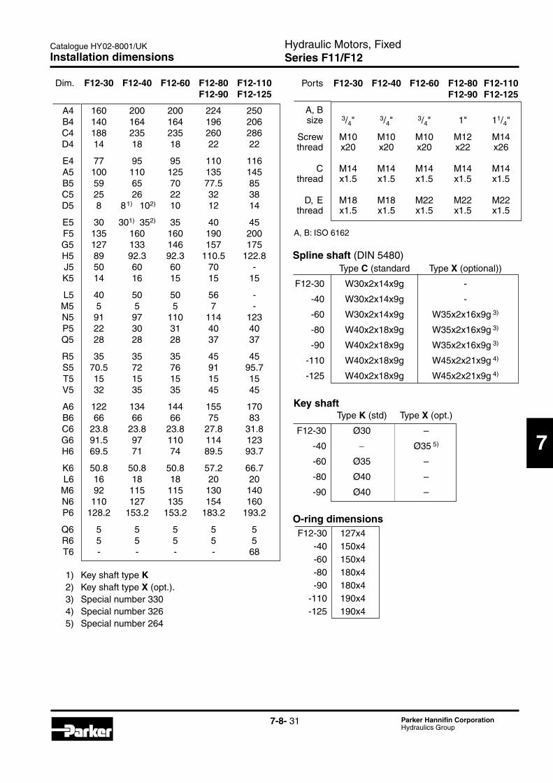
Dim. F12-30 F12-40 F12-60 F12-80 F12-110 F12-90 F12-125
A4 160 200 200 224 250 B4 140 164 164 196 206 C4 188 235 235 260 286 D4 14 18 18 22 22
E4 77 95 95 110 116 A5 100 110 125 135 145 B5 59 65 70 77.5 85 C5 25 26 22 32 38 D5 8 81) 102) 10 12 14
E5 30 301) 352) 35 40 45 F5 135 160 160 190 200 G5 127 133 146 157 175 H5 89 92.3 92.3 110.5 122.8 J5 50 60 60 70 - K5 14 16 15 15 15
L5 40 50 50 56 - M5 5 5 5 7 - N5 91 97 110 114 123 P5 22 30 31 40 40 Q5 28 28 28 37 37
R5 35 35 35 45 45 S5 70.5 72 76 91 95.7 T5 15 15 15 15 15 V5 32 35 35 45 45
A6 122 134 144 155 170 B6 66 66 66 75 83 C6 23.8 23.8 23.8 27.8 31.8 G6 91.5 97 110 114 123 H6 69.5 71 74 89.5 93.7
K6 50.8 50.8 50.8 57.2 66.7 L6 16 18 18 20 20 M6 92 115 115 130 140 N6 110 127 135 154 160 P6 128.2 153.2 153.2 183.2 193.2
Q6 5 5 5 5 5 R6 5 5 5 5 5 T6 - - - - 68
1) Key shaft type K 2) Key shaft type X (opt.). 3) Special number 330 4) Special number 326 5) Special number 264
Ports F12-30 F12-40 F12-60 F12-80 F12-110 F12-90 F12-125
A, B size 3/4" 3/4" 3/4" 1" 11/4"
Screw M10 M10 M10 M12 M14 thread x20 x20 x20 x22 x26
C M14 M14 M14 M14 M14 thread x1.5 x1.5 x1.5 x1.5 x1.5
D, E M18 M18 M22 M22 M22 thread x1.5 x1.5 x1.5 x1.5 x1.5
O-ring dimensions F12-30 127x4 -40 150x4 -60 150x4 -80 180x4 -90 180x4 -110 190x4 -125 190x4
Type C (standard Type X (optional))
F12-30 W30x2x14x9g -
-40 W30x2x14x9g -
-60 W30x2x14x9g W35x2x16x9g 3)
-80 W40x2x18x9g W35x2x16x9g 3)
-90 W40x2x18x9g W35x2x16x9g 3)
-110 W40x2x18x9g W45x2x21x9g 4)
-125 W40x2x18x9g W45x2x21x9g 4)
Type K (std) Type X (opt.)
F12-30 Ø30 –
-40 − Ø35 5)
-60 Ø35 –
-80 Ø40 –
-90 Ø40 –
Spline shaft (DIN 5480)
A, B: ISO 6162
Key shaft
Installation dimensions

7-8- 32 Parker Hannifin CorporationHydraulics Group
Hydraulic Motors, FixedSeries F11/F12
Catalogue HY02-8001/UK
F12_80_SAE_4bolt_inst.epsLeif A./020204
A7
A7 ØD7 (x4)
B7
C7
T9
A8
G8
J8
N8
L8
M8D8
ØE8
ØF8
H8
K8
B8
C8
A9B9
K9
L9
C9
G9
H9J9
F9
R8
Q8D9
ØE9
Shown: F12-80 with 4 bolt flange
Type S (SAE 4 bolt) mounting flange
Port E (third drain port)F12-110 and -125 barrel housing
(SAE version)
Port A Port B
Port C1)
Speed sensor
(optional)
Type Sflange
1) Inspection/ drain port
See
table
Type S (U) spline shaft
Type T key shaft
Flushing valve
(optional)
Port D
F12-30, -40, -60, -80, -90, -110 and -125(SAE versions with 4 bolt flange)
Installation dimensions

7-8- 33 Parker Hannifin CorporationHydraulics Group
Hydraulic Motors, FixedSeries F11/F12
Catalogue HY02-8001/UK
7
Key shaft (SAE J744) T (standard) X (optional)
F12-30 SAE 'B-B' - (Ø25.4 mm/1") -40 SAE 'C' - (Ø31.75 mm/11/4") -60 SAE 'C' - (Ø31.75 mm/11/4") -80 SAE 'C-C' SAE ’D’ (Ø38.1 mm/11/2") (Ø44.45 mm/13/4")5)
-90 SAE 'C-C' SAE ’D’
(Ø38.1 mm/11/2") (Ø44.45 mm/13/4")5)
-110 SAE 'D' - (Ø44.45 mm/13/4") -125 SAE 'D' - (Ø44.45 mm/13/4")
Mounting flange (SAE J744) S (standard) X (optional) F12-30 SAE 'B', 4 bolt - -40 SAE 'C', " - -60 SAE 'C', " - -80 SAE 'C', " SAE ’D’, 4 bolt3)
-90 SAE 'C', " SAE ’D’, 4 bolt3)
-110 SAE 'D', " - -125 SAE 'D', " -
Dim. F12-30 F12-40 F12-60 F12-80 F12-110 F12-90 F12-125
A7 89.8 114.5 114.5 114.5 161.6 B7 118 148 148 155 204 C7 118 144 144 155 200 D7 14 14 14 14 21
A8 100 110 125 135 145 B8 59 65 70 77.5 85 C8 25 26 22 32 38
D8 6.35 7.94 7.94 9.53 11.1 E8 33 42 42 52 57.5 F8 101.60/ 127.00/ 127.00/ 127.00/ 152.40/ 101.55 126.94 126.94 126.94 152.34
G8 189.5 197 214 240 264 H8 8 8 8 8 8 J8 38 48 48 54 67
K8 72 76 79 95 99 L8 31.8 38.1 38.1 44.5 54.1 M8 2.5 4 4 4 7.5
N8 153.5 161 178.3 197.1 212 Q81) 23 23 23 25 34 Q82) - - - 23 - R81) 33 48 48 54 66.7 R82) - - - 48 -
A9 122 134 144 155 170 B9 66 66 66 75 83 C9 23.8 23.8 23.8 27.8 31.8
D9* 5/16"-24 3/8"-24 3/8"-24 1/2"-20 5/8"-18 E9 25.40/ 31.75/ 31.75/ 38.10/ 44.45/ 25.35 31.70 31.70 38.05 44.40 F9 28.2 35.3 35.3 42.3 49.4
G9 153.8 161 178.3 197.1 212 H9 9.7 12.7 12.7 12.7 12.7 J9 16 19 19 26 32
K9 50.8 50.8 50.8 57.2 66.7 L9 18 20 20 20 22 T9 - - - - 68
* UNF-2B thread 4) Special number 255 1) Spline shaft type S 5) Special number 254 2) Spline shaft type U 6) Special number 328 3) Special number 254 or 255
Main ports A and B, type U (optional)
F12-80 1 5/16" - 12 UN
F12-90 1 5/16" - 12 UN
F12-110 1 5/8" - 12 UN
F12-125 1 5/8" - 12 UN
O-ring ports according to SAE J514d
Ports F12-30 F12-40 F12-60 F12-80 F12-110 F12-90 F12-125
A, B size 3/4" 3/4" 3/4" 1" 11/4"
Screw 3/8"-16 3/8"-16 3/8"-16 7/16"-14 1/2"-13thread3) x22 x20 x22 x27 x25
C thread 7/8"-14 7/8"-14 7/8"-14 7/8"-14 11/16"-12
D thread 3/4"-16 3/4"-16 7/8"-14 7/8"-14 11/16"-12
E thread - - - - 11/16"-12
A, B: ISO 6162 C, D, E: O-ring boss (SAE J514)3) UN thread x depth in mm.
Spline shaft (SAE J498b, class 1, flat root, side fit) S (standard) U (opt.) X (optional)
F12-30 SAE 'B' - - 13T, 16/32 DP -40 SAE 'C' 14T, - - 12/24 DP -60 SAE 'C' 14T, - 21T, 16/32DP6)
12/24 DP -80 SAE 'C-C' SAE 'C' SAE 'D' 17T, 12/24 DP 14T,12/24DP 13T, 8/16 DP4)
-90 SAE 'C-C' SAE 'C' SAE 'D'
17T, 12/24 DP 14T,12/24DP 13T, 8/16 DP4)
-110 SAE 'D' - - 13T, 8/16 DP -125 SAE 'D' - - 13T, 8/16 DP
= Max 350 bar operating pressure.
Installation dimensions

7-8- 34 Parker Hannifin CorporationHydraulics Group
Hydraulic Motors, FixedSeries F11/F12
Catalogue HY02-8001/UK
F12_60_SAE_2bolt_inst.epsLeif A./020204
ØD10(x2)
A10
B10
G11
J11 D11
A11 B11
C11
N11
L12
A12
B12C12
G12
H12
K12
J12
F12
D12
ØE12
L11
M11ØE11
ØF11
K11
H11 R11
Q11
F10
E10 RC10 R
Port A Port BPort D
Flushing valve
(optional)
Type T key shaft Type T
flange
Speed sensor
(optional)
1) Inspection/ drain port
Port C1)
Type T (SAE 2 bolt) mounting flange
Shown: F12-60 with 2 bolt flange
See
table
Type S spline shaft
F12-30, -40, and -60(SAE versions with 2 bolt flange)
Installation dimensions

7-8- 35 Parker Hannifin CorporationHydraulics Group
Hydraulic Motors, FixedSeries F11/F12
Catalogue HY02-8001/UK
7
Ports F12-30 F12-40 F12-60
A, B 19 19 19 size (3/4") (3/4") (3/4")
Screw 3/8"-16 3/8"-16 3/8"-16 thread 2) x22 x20 x22
C 3/4"-16 3/4"-16 7/8"-14 thread
D 3/4"-16 3/4"-16 7/8"-14 thread
A, B (main ports): SAE J518c (6000 psi)C, D (drain ports): O-ring boss (SAE J514)2) UN thread
Main ports A and B, type U (optional)
F12-30 1 1/16" - 12 UN -40 1 5/16" - 12 UN -60 1 5/16" - 12 UN
O-ring ports according to SAE J514d
= Max 350 bar operating pressure.
Dim. F12-30 F12-40 F12-60 A10 146 181 181 B10 176 215 215 C10 63 74 74
D10 14.4 17.5 17.5 E10 10 16 16 F10 10 15.5 15.5
A11 100 110 125 B11 59 65 70 C11 25 26 22
D11 6.35 7.94 7.94 E11 33 42 42 F11 101.60/ 127.00/ 127.00/ 101.55 126.95 126.95
G11 189.5 197 214 H11 8 8 8 J11 38 48 48
K11 71 77 81.5 L11 31.8 38.1 38.1 M11 2.5 4 4
N11 154 161 178.5 Q11 26 27 27 R11 33 48 48
A12 122 134 144 B12 66 66 66 C12 23.8 23.8 23.8
D121) 5/16"-24 3/8"-24 3/8"-24 E12 25.40/ 31.75/ 31.75/ 25.35 31.70 31.70 F12 28.2 35.2 35.2
G12 154 161 178.5 H12 9.7 12.7 12.7 J12 16 19 19
K12 50.8 50.8 50.8 L12 18 20 20
1) UNF-2B thread
Mounting flange T (SAE J744)
F12-30 SAE 'B', 2 bolt
-40 SAE 'C', 2 bolt
-60 SAE 'C', 2 bolt
Spline shaft S (SAE J498b, class 1, flat root, side fit)
F12-30 SAE 'B' 13 T; 16/32 DP
-40 SAE 'C' 14 T; 12/24 DP
-60 SAE 'C' 14 T; 12/24 DP
Key shaft T (SAE J744)
F12-30 SAE 'B-B' Ø25.4 mm/1"
-40 SAE 'C' Ø31.75 mm/11/4"
-60 SAE 'C' Ø31.75 mm/11/4"
Installation dimensions
7-8- 36 Parker Hannifin CorporationHydraulics Group
Hydraulic Motors, FixedSeries F11/F12
Catalogue HY02-8001/UK
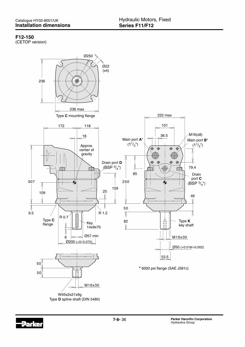
F12-150(CETOP version)
Installation dimensions
F11_150_CETOP_install.epsLeif A./020204
109 25159
307
172 118
18
Ø57 min
Ø250
Ø22(x4)
236 max
236
222 max
101
85
M16x30
M16x30
250
50
6
82
46
M16(x8)
50
50
W45x2x21x9g
Approx. center of gravity
Type C mounting flange
Type K key shaftKey
14x9x70
Type Cflange
Type D spline shaft (DIN 5480)
* 6000 psi flange (SAE J581c)
R 0.7R 1.2
Ø200 (+0/-0.072)
36.5
79.4Drain port D(BSP 3/4")
Drain port C
(BSP 3/4")
Main port A*(11/2")
Main port B*(11/2")
Ø50 (+0.018/+0.002)
53.5
9.5

7-8- 37 Parker Hannifin CorporationHydraulics Group
Hydraulic Motors, FixedSeries F11/F12
Catalogue HY02-8001/UK
7
Installation dimensions
F12-150(SAE version)
15724
206
355
85
297
172 118
18
222 max
101M16(x8)**
214
21 (4x)
192
8
SAE 'D'; 13T, 8/16 DP;class 1, flat root, side fit
8
Ø57 min
Approx. center of gravity
Type S mounting flangeSAE ‘D’ (SAE J744c)
Type S flange
Key11.11x11.11x54
Type T key shaftSAE‘D’
(SAE J744c)
Type S spline shaft (SAE J498b)
* 6000 psi flange (SAE J581c)
161.6
161.6
66.7
6.7
R 0.8R 0.8
36.5
12.7
66.7
49.3
79.4
Main port A*(11/2")
Main port B*(11/2")
Drain port D(BSP 3/4")
Drain port C
(BSP 3/4")
Ø152.4 (+0/+0.05)Ø44.45 (+0./+0.05)
5/8-18 UNFdepth 30
5/8-11 UNCdepth 35

7-8- 38 Parker Hannifin CorporationHydraulics Group
Hydraulic Motors, FixedSeries F11/F12
Catalogue HY02-8001/UK
F12-250 (SAE version)
Installation dimensions
F11_250_SAE_install.eps
Leif A./020204
232
101
141
M16x31min
M16x31min
336
200max
M16x35(x8)
197 118
24
27
200 max
Ø21(x4)
Ø57 min
4855
8
Ø39 (x2)
180
395
82 6
216
35
SAE F; 15T, 8/16 DP;class 1, flat root, side fit
Approx. center of gravity
Type S mounting flangeSAE ‘D’ (SAE J744c)
Key14x9x70
Type K key shaft(metric; not SAE)
Type F spline shaft (SAE J498b)
Optional: Type S spline shaft: 13T 8/16 DP
* 6000 psi flange (SAE J518c)
161.6
161.6
R 0.8
12.7
53.5
Ø49.6
66.7
7.9
R 0.7
7.9
36.5
79.38
Main port A*(11/2")
Main port B*(11/2")
Drain port D(BSP 3/4")
Drain port C
(BSP 3/4")
Ø50 (+0.018/+0.002)
Ø152.4 (+0/+0.05)
Type D spline shaft W50x2x24x9g
(DIN 5480)

7-8- 39 Parker Hannifin CorporationHydraulics Group
Hydraulic Motors, FixedSeries F11/F12
Catalogue HY02-8001/UK
7
F11 in saw motor applicationsSeries F11 motors have proven suitable for demanding applications such as chain saws. Primarily due to the 40° bent-axis design, spherical pistons (with laminated piston rings) and gear synchronization, very high speeds are permissible. Not even low temperatures at start-up affect reliability.To further enhance the saw function and, at the same time, reduce weight, cost and installation dimensions, a specific saw motor has been developed (frame sizes-10, -14 and -19; refer to the illustration to the right)which is specifically dedicated to bar saws. The motor allows the saw bar bearings to be mounted directly on the motor housing, and the sprocket installs on the mo-tor shaft without additional bearings.For more detailed information (available versions, ordering codes, installation dimensions, etc.), refer to 'F11 Saw Motors' (catalogue HY30-8245).
F11_saw_motor_install.epsLeif A./020204
F11 with built-in make-up valve
Saw bar supported directly on the motor flange
Feed cylinder
Chain sprocket mounted directly on the shaft
Saw chain
Protective cover
Saw bar
Chainsawinstallation(example;F11-10shown)
sure levels (up to max allowed for the motor) will, of course, increase the performance even further.
Through the whole cut the corresponding flow into the unit should, at least, be:- 180 l/min @ 8 500 rpm and 14-tooth chain sprocket- 195 l/min @ 9 200 rpm and 13-tooth chain sprocket- 210 l/min @ 9 900 rpm and 12-tooth chain sprocket.As a consequence, the pump must be able to deliver at least a 5% higher flow than what is shown above to properly secure the saw function.In order to utilize the full potential of the saw motor, it is most important to minimize pressure losses in the hydraulic system as much as possible. Avoid using so called 'banjo' couplings and make sure there are no sharp bends in the utilized hydraulic hoses, couplings and hydraulic piping.The saw motor unit has a motor flushing function which is integrated with the sword feed function. By connect-ing the drain port "D" directly to tank, additional flush-ing will usually not be required.As the saw bar feed function is of a re-generative type (refer to the saw function on page 40) a 40/30 or 40/25 mm feed cylinder is recommended; this will ensure the best cutting performance of the saw.If another cylinder configuration is being considered, please contact Parker Hannifin.The electric signal to the 'start/stop' solenoid which starts the cutting cycle must be of the 'no ramp' type, so that the saw motor can start immediately without delay; otherwise, there may be a risk of motor break-down.NOTE: The chain saw function is covered on page 40For more detailed information (available versions, ordering codes, installation dimensions, etc.), refer to 'F11 Saw Motors' (catalogue HY30-8251).
Benefits• Simple installation means lower cost• Low overall weight• Compact installation• Reduced motor shaft loading• Improved performance• Controlled cutting process.
Saw motor requirements and recommendationsIn order to obtain the most satisfactory function of the saw motor, the hydraulic system of the machine must be able to maintain a system pressure through the whole cut of at least 220 bar at the motor; higher pres-
Series F11iPThe saw motor unit has integrated functions for start/ stop and speed control, which means long motor life.The saw motor also controls the saw bar feed function, which provides optimal chain speed and saw perform-ance during the entire cutting process.To further enhance the saw function and, at the same time, reduce weight, cost and installation dimensions,Parker Hannifin has thus developed a motor unit which is specifically dedicated to chain saws.
Technical information

7-8- 40 Parker Hannifin CorporationHydraulics Group
Hydraulic Motors, FixedSeries F11/F12
Catalogue HY02-8001/UKTechnical information
Functional_schematic_return.aiLeif A./07-05-10
A
B
F E
D
1 2
4
C
3
Functional_schematic_cut.aiLeif A./07-05-10
D
F EA
C
B
1
4
3
2
Cutting mode (refer to the top schematic)The machine operator activates the start/stop function '4' which starts the saw motor. When the motor reaches operating speed, the cylinder piston side (port 'E') is drained and the cutting bar starts to move 'down'.
The drain flow (through port 'E' and valve '2'), provides cooling to the motor case.
Chain saw function
Return mode (refer to the bottom schematic)When the tree or log has been cut through, the operator de-activates the start/stop solenoid valve '4'. Valve spools '2' and '3' move to the 'up' position and the motor stops turning.
At the same time both sides of the cylinder are pressu-rized and the cutting bar moves 'up' to the start position (because of the re-generative cylinder/valve hook-up).
Chain saw function - return mode.
- The connected spool valve functions, '2' and '3', control the speed of the motor as well as the saw bar speed.
NOTE: - The pressure compensated pump is operating during the entire cutting cycle. - The pressure reducing valve, '1', reduces the pressure to the saw bar cylinder.
Chain saw function - cutting mode.
7-8- 41 Parker Hannifin CorporationHydraulics Group
Hydraulic Motors, FixedSeries F11/F12
Catalogue HY02-8001/UK
7
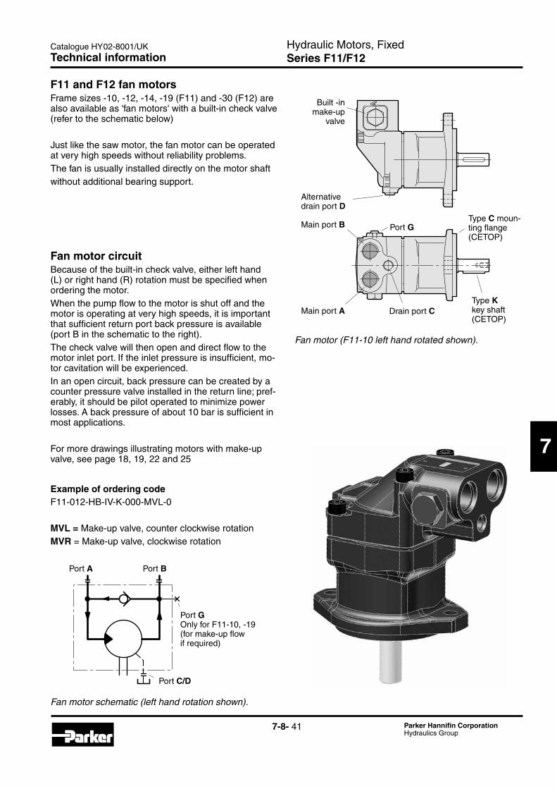
F11_fan_motor.epsLeif A./020204
Port G
Built -in make-up
valve
Alternative drain port D
Main port B
Main port A Drain port CType K key shaft (CETOP)
Type C moun-ting flange (CETOP)
Fan_motor_schem.epsLeif A./020204
Port A Port B
Port G Only for F11-10, -19 (for make-up flow if required)
Port C/D
Fanmotor(F11-10lefthandrotatedshown).
Fanmotorschematic(lefthandrotationshown).
Technical information
F11 and F12 fan motorsFrame sizes -10, -12, -14, -19 (F11) and -30 (F12) are also available as 'fan motors' with a built-in check valve (refer to the schematic below)
Just like the saw motor, the fan motor can be operated at very high speeds without reliability problems.The fan is usually installed directly on the motor shaftwithout additional bearing support.
Fan motor circuitBecause of the built-in check valve, either left hand (L) or right hand (R) rotation must be specified when ordering the motor.When the pump flow to the motor is shut off and the motor is operating at very high speeds, it is important that sufficient return port back pressure is available (port B in the schematic to the right).The check valve will then open and direct flow to the motor inlet port. If the inlet pressure is insufficient, mo-tor cavitation will be experienced.In an open circuit, back pressure can be created by a counter pressure valve installed in the return line; pref-erably, it should be pilot operated to minimize power losses. A back pressure of about 10 bar is sufficient in most applications.
For more drawings illustrating motors with make-up valve, see page 18, 19, 22 and 25
Example of ordering codeF11-012-HB-IV-K-000-MVL-0
MVL = Make-up valve, counter clockwise rotationMVR = Make-up valve, clockwise rotation
7-8- 42 Parker Hannifin CorporationHydraulics Group
Hydraulic Motors, FixedSeries F11/F12
Catalogue HY02-8001/UK
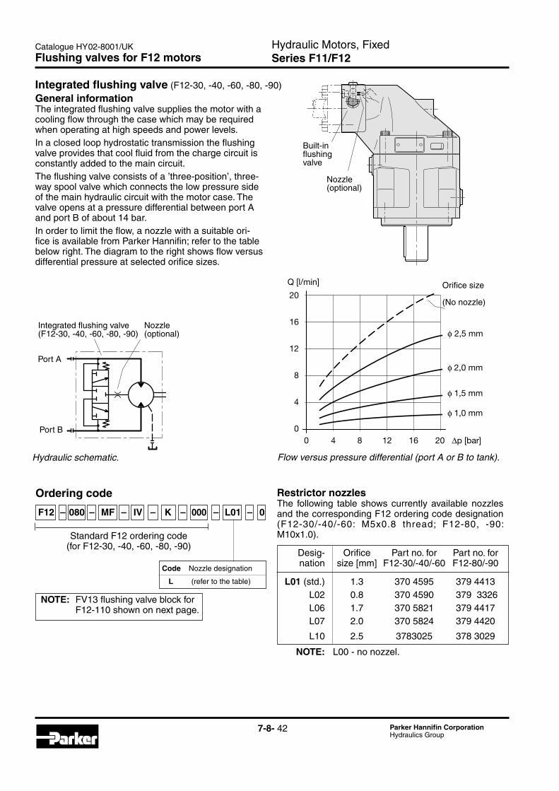
Restrictor nozzlesThe following table shows currently available nozzles and the corresponding F12 ordering code designation (F12-30/-40/-60: M5x0.8 thread; F12-80, -90: M10x1.0).
Desig- Orifice Part no. for Part no. for nation size [mm] F12-30/-40/-60 F12-80/-90
L01 (std.) 1.3 370 4595 379 4413 L02 0.8 370 4590 379 3326 L06 1.7 370 5821 379 4417 L07 2.0 370 5824 379 4420
L10 2.5 3783025 378 3029
NOTE: L00 - no nozzel.
Flowversuspressuredifferential(portAorBtotank).
General informationThe integrated flushing valve supplies the motor with a cooling flow through the case which may be required when operating at high speeds and power levels. In a closed loop hydrostatic transmission the flushing valve provides that cool fluid from the charge circuit is constantly added to the main circuit.The flushing valve consists of a ’three-position’, three-way spool valve which connects the low pressure side of the main hydraulic circuit with the motor case. The valve opens at a pressure differential between port A and port B of about 14 bar.In order to limit the flow, a nozzle with a suitable ori-fice is available from Parker Hannifin; refer to the table below right. The diagram to the right shows flow versus differential pressure at selected orifice sizes.
Hydraulicschematic.
F12_60_FV_install.epsLeif A./03-01-27
Built-influshingvalve
Nozzle(optional)
0 4 8 12 16 20 ∆p [bar]
Q [l/min]
20
16
12
8
4
0
φ 2,5 mm
φ 2,0 mm
φ 1,5 mm
φ 1,0 mm
Orifice_Q_p_diagram.epsLeif A./03-01-27
Orifice size
(No nozzle)
F12_FV_schem.epsLeif A./03-01-27
Port A
Port B
Integrated flushing valve(F12-30, -40, -60, -80, -90)
Nozzle(optional)
Flushing valves for F12 motors
Ordering code
F12 – 080 – MF – IV – K – 000 – L01 – 0
Standard F12 ordering code (for F12-30, -40, -60, -80, -90)
Code Nozzle designation
L (refer to the table)
NOTE: FV13 flushing valve block for F12-110 shown on next page.
Integrated flushing valve (F12-30, -40, -60, -80, -90)

7-8- 43 Parker Hannifin CorporationHydraulics Group
Hydraulic Motors, FixedSeries F11/F12
Catalogue HY02-8001/UK
7
F12_110_FV13_view.epsLeif A./03-01-27
FV13 valve block
Restrictor nozzle
F12-110 motor
General information (for F12-110, -125)The FV13 for the F12-110 / -125 motor has the same function as the integrated flushing valve for the other F12 frame sizes. The valve block mounts between the motor port flange and the split-flange tube/hose connec-tors utilizing ’long’ mounting screws (screw size M14x75 or 1/2"-13 UNC based on split-flange height as shown below).The FV13 flushing valve kit contains the required O-rings (shown below) but no screws, split-flanges or tube/hose connectors.
FV13 installation
FV13 restrictor nozzlesWhen required, a nozzle is utilized to restrict the flow through the F12-110, -125 motor case. The nozzle installs in the drilled and tapped (M10x1.0) drain line located in the valve block as shown to the left. The dia-gram on page 1 shows flushing flow versus differential pressure for selected orifice sizes. The following table lists currently available nozzles and the corresponding FV13 ordering code designa-tion.
Desig- Flushing Orifice Orifice nation valve size Part Part number [mm] number
L00 no nozzle 3780292 L01 (std.) 3795623 1.3 379 4413 L04 3780593 1.2 379 4412 L06 3787315 1.7 379 4417 L07 3798322 2.0 379 4420
Hydraulicschematic.F12_FV13_schem.epsLeif A./03-01-27
Port A
Port B
Nozzle (optional)
FV13 flushing valve block
(27)
25
47
92
44
38
83
1427
φ 32(x2)
FV13_install.epsLeif A./03-01-27
Nozzle
Weight:2.9 kg
15.5 dia. (x8)
Tube/hoseconnector
Splitflange
FV13 valveblock
O-ring29.2x3.0
O-ring37.69x3.53 (x2)
31.8
66.7
FV13 flushing valve block
FV13_squares.epsLeif A./03-01-28
FV13 Ordering code
FV 1 3 – H – A – L01
Valve Version Size Seals Techn. Nozzel type status
Flushing Code Nozzel valve L Table below
Code Version Code Techn. status 1 Factory A Factory assigned assigned
Code Size (SAE 6000 psi) Code Seals 3 11/2" (for F12-110 / -125) H Nitrile rubber

7-8- 44 Parker Hannifin CorporationHydraulics Group
Hydraulic Motors, FixedSeries F11/F12
Catalogue HY02-8001/UK
General information- The SR pressure relief/make-up valve block for series F12 and V12 motors is designed to protect the motor and the main hydraulic lines from short duration pressure spikes. The valve block also provides an excellent make-up function.- The valve block installs directly on the motor port flange, and is available in three sizes: 1 3/4" for F12-30/-40/-60, T12-60 and V12-60/-80 2 1" for F12-80, -90, T12-80 and V14-110 3 11/4" for F12-110, -125 and V14-160.- The SR valve block consists of a housing containing two high pressure relief cartridges and two separate check valves for make-up. Cartridges are available in non-adjustable pressure settings between 280 and 420 bar (4000and6000psirespectively).- A make-up port (G) is also provided. In certain opera ting conditions, the motor (when operating as a pump) may cavitate because of insufficient inlet pressure. To prevent this, the G port should be pressurized. Contact Parker Hannifin for further information.- The pressure drop through the main ports (A–A' or B–B') is low. As an example, the pressure drop on size 1 (3/4") is 0.45 bar (6.5psi) at 175 l/min, and on size 2 (1") 0.7 bar (10psi) at 250 l/min.
NOTE: The valve block includes main port O-rings (facing the motor) but no mounting screws.
SRvalveblocklocation.
SRvalveblockschematic.F12_SR_schem_SE.epsLeif A./03-01-27
Port B
Port A
Port G SR valve block F12 motor
F12_SR_install.epsLeif A./03-01-31
Port G
SR valve block
SR pressure relief / make-up valve
SR_SV_squares.epsLeif A./03-01-29
Ordering code
SR 1 – / – 00 – H F – A
Valve Version Port Serial Seals Threads Techn. function size Pressure settings number status
Pressure relief/ make-up valve block Code Version
1 Factory assigned Code Port size (SAE 6000 psi)
1 3/4" For: F12-30, -40, -60, T12-60 and V12-60, -80 2 1" For: F12-80, -90, T12-80 and V14-110 3 11/4" For: F12-110, -125 and V14-160
Code Pressure settings (A/B ports) [bar]
280, 300, 330, 350, 380, 400 or 420
Code Techn. status
A Factory assigned
Code Threads (port G)
F Metric
Code Seals
H Nitrile rubber
Code Serial number
00 Factory assigned

7-8- 45 Parker Hannifin CorporationHydraulics Group
Hydraulic Motors, FixedSeries F11/F12
Catalogue HY02-8001/UK
7
SV pressure relief valveGeneral information- The SV pressure relief valve block for series F12 and V12 motors is designed to protect the motor and adjacent hydraulic components from short duration pressure peaks. - It installs directly on the motor port flange and is available in three sizes: ’1’: 3/4" for F12-30/-40/-60, T12-60 and V12-60/-80 ’2’: 1" for F12-80/ -90, T12-80 and V14-110 ’3’: 11/4" for F12-110/-125 and V14-160- The valve block consists of a housing containing two high pressure relief cartridges with anti-cavitation function. Cartridges are available in non-adjustable pressure settings between 280 and 420 bar.- A make-up/drain port, L, is also provided. In certain operating conditions the motor may cavitate because of in-sufficient inlet pressure. To prevent this, the L port can be pressurized. When there is a risk of over- heating, the L port can also be utilized to take out part of the flow for cooling. Contact Parker Hannifin for further information.- The pressure drop through the main ports (A–A' or B–B') is low. As an example, the pressure drop on size 1 (3/4") is 0.45 bar (6.5psi) at 175 l/min (45gpm), and on size 2 (1") 0.7 bar (10psi) at 250 l/min (65gpm).
NOTE: - The valve block includes main port O-rings (facing the motor) but no mounting screws. - The valve blocks can be used on all versions of series F12 as well as V12 and T12 motors.
SVvalveblockinstalledonanF12motor.
Hydraulicschematic.
Dim. Size 1 Size 2 Size 3 [mm] (3/4") (1") (11/4")
A 55 57 57 B 55 55 25
C 32 32 26 D 157 160 160 E 66 75 83
F 23.8 27.8 31.8 G 50.8 57.15 66.7 H 103 109 88
J 140 150 135 K 18 18 - L 16 16 16
M 78.5 80 - N M10 M12 M14 x18 x20 x23 P 11 13 15.5
Weight Size 1 Size 2 Size 3 [kg] (3/4") (1") (11/4")
7.4 9.1 8.5
F12_80_SV_install.epsLeif A./03-01-31
SV pressure reliefvalve block
F12_SV_schematic.epsLeif A./03-01-29
(F12)SV valve block Port B’
Port L Port A’
Port A
Port B
C L M
D
E
FA φ P(x6)
K
G
H
B
J
SR11_install.epsLeif A./03-01-27
Checkvalve
Reliefvalvecartridge
Facingthe motor
PortsA/A’
PortsB/B’
Nthread
Port L
Port G(size 1 and 2)
M22x1.5; min 16 deep
Installation dimensions

7-8- 46 Parker Hannifin CorporationHydraulics Group
Hydraulic Motors, FixedSeries F11/F12
Catalogue HY02-8001/UK
SV_install.epsLeif A./03-01-27
A
B
F
E
G
φ K (x8)
H
J
D
C
Facingthe motor
Port BPort A
Make-up port L(M22x1.5)
Port A Port Brelief valve cartr.
Installation
Ordering code
Dim. [mm] SV11 SV12 SV13 A 71 73 73 B 31 31 31 C 36 41 47 D 47 51 68 E 130 127 142 F 66 75 83 G 23.8 27.8 31.8 H 50.8 57.2 66.7 J 99 109 135 K 11 13 15.5
Weight [kg] 4.2 5.0 6.7
SR_SV_squares.epsLeif A./03-01-29
SV 1 – / – 00 – H F – A
Valve Version Port Serial Seals Threads Techn. function size Pressure setting number (port L) status
Pressure relief valve
Code Version 1 Factory assigned
Code Port size (SAE 6000 psi) 1 3/4" (F12-30/-40/-60, T12-60, and V12-60/-80) 2 1" (F12-80/-90, T12-80 and V14-110) 3 11/4" (F12-110/-125 and V14-160)
Code Pressure setting (A/B ports) [bar]
280, 300, 330, 350, 380, 400 or 420
Code Techn. status
A Factory assigned
Code Threads (port L) F Metric
Code Seals H Nitrile rubber
Code Serial number 00 Factory assigned

7-8- 47 Parker Hannifin CorporationHydraulics Group
Hydraulic Motors, FixedSeries F11/F12
Catalogue HY02-8001/UK
7
SPvalvecomponents.
The SP, super shockless, pressure relief/make-up valve block for series F12 motors is designed mainly for pro-tection of the swing function of an excavator. It features a very ’soft’ relief characteristic with very little overshoot and an excellent make-up function.The pressure/time diagram to the right is a recording of an actual start-brake sequence of an excavator swing function. In the left part (’Start’), port A is pressurized and the swing is accelerating; the pump pressure is limited by the relief valve setting. In the right part (’Brake’), port B is pressurized (as deter-mined by the relief valve setting), and the swing movement stops. The valve block installes directly on the motor port flange, and is available in three sizes: SP11 3/4" for F12-30/-40/-60 SP12 1" for F12-80/-90 SP13 11/4" for F12-110/-125 The SP valve consists of a valve block containing two high pressure relief cartridges and two separate check valves for make-up; refer to the split view below. Cartridges are available in five non-adjustable pressure settings between 190 and 315 bar.A make-up port (G) is also provided. In certain operating conditions, the motor (when operating as a pump) may cavitate because of insufficient inlet pressure. To prevent this, the G port should be pressurized. Contact Parker Hannifin, for further information.NOTE: The valve block includes main port O-rings (facing the motor) but no mounting screws.
SP/F12schematic.
Pressure/timediagram(example).
SP_schematic.epsLeif A./03-02-19
SP valve block F12 motorPort A1
Port B1
Port BM (M12x1.5)
Port G(M22x1.5)
Port AM(M12x1.5)
Port L(M27x2)
Port A
Port B
AM
L
SP_valve_components.epsLeif A./03-02-19
Pressure reliefcartridge
Facing split-flanges
Check valve(x2; one opposite)
Valveblock
SP_diagram.epsLeif A./03-02-19
300
200
100
0 0 1,0 5,0 6,0
Port A Port B
Port B Port A
Start Brake
Time[s]
Pressure[bar]
SP super shockless, pressure relief valve

7-8- 48 Parker Hannifin CorporationHydraulics Group
Hydraulic Motors, FixedSeries F11/F12
Catalogue HY02-8001/UK
Installation dimensions (refer to the illustration)
Valve For For For type F12-30/-40/-60 F12-80/-90 F12-110/-125
A 63 66 70 B 156 160 160 C 23.8 27.8 31.8 D 66 75 83 E 207 207 225 F 133 133 151 G 97 97 115 H 11 13 15 J 3/4" 12 11/4" K 24.99x3.53 32.93x3.53 37.69x3.53 M M10 M12 M14 (20 deep) (20 deep) (26 deep) Art. No 0686 371 810 0663 918 801 0663 919 101
Valve assembly part numbers For motor Pressure setting [bar] at 20 l/min1)
type 190 220 250 285 315
F12-30/ 376 6320 376 4631 376 3674 -40/-60 376 7157 376 3675
F12-80/ 376 7161 376 6924 376 3677 -90 376 7158 376 3678
F12-110/ 376 7162 376 7163 376 3679 -125 376 7159 376 7164
1) Setting within ±10 bar
Pressure relief cartridges Cartridge Pressure setting [bar] at 20 l/min1)
type 190 220 250 285 315
Spare part 376 4610 376 4632 376 3825 number 376 7156 376 3824
SS_valve_install.epsLeif A./03-01-30
L
BM
AC
D φ H(x6)
φ J
B
E
F
GGauge port BM(plugged; portAM opposite)
Pressure reliefcartridge (x2;one opposite)
Facing motor
K (O-ring; x2;opposite)
M thread(x2)
Port L
Ordering code
SP_squares.epsLeif A./03-01-29
SP 1 – / – 00 – H F – A
Valve Port size Serial Threads
function number (port. G) Version Pressure setting Seals Techn. status
Code Tech. status A Factory assigned
Code Threads (port G)
F Metric
Code Seals H Nitrile rubber
Code Serial number 00 Factory assigned
Pressure relief/ make-up valve
Code Version 1 Factory assigned
Code Port size (SAE 6000 psi)
1 3/4" (F12-30, -40, -60) 2 1" (F12-80, -90) 3 11/4" (F12-110, -125)
Code Pressure setting (A and B ports) [bar]
190, 220, 250, 285 or 315
SP valve installation

7-8- 49 Parker Hannifin CorporationHydraulics Group
Hydraulic Motors, FixedSeries F11/F12
Catalogue HY02-8001/UK
7
F12_speed_sensor.epsLeif A./020204
Speed sensor
A speed sensor kit is available for series F11/F12. A ferrostat differential (Hall-effect) sensor installs in a separate, threaded hole in the F11/F12 bearing housing .On F12 the speed sensor is directed towards the ring gear. On F11 the speed sensor is directed towards the pistons. The sensor output is a 2 phase shifted square wave signal within a frequency range of 0 Hz to 15 kHz.
NOTE: - The motor bearing housing must be prepared for the speed pick-up; refer to the F11/F12 ordering codes (pages 7-12). - On F11 the pistons position must be known before mounting.
- Additional information is provided in the Instruction (catalogue HY30-8301/UK). - The speed sensor is also shown in the illustrations on pages 18, 19, 22, 23, 25, 26, 28, 30, 32 and 34.
Part number for Speed sensor is 378 5190.
Speed sensor
F12withspeedsensor.
F11-14withspeedsensor.
Speed sensor

7-8- 50 Parker Hannifin CorporationHydraulics Group
Hydraulic Motors, FixedSeries F11/F12
Catalogue HY02-8001/UK
Series F12
Frame size Speed [rpm] Flow [l/min]
F12-30 3500 4–8 F12-40 3000 5–10 F12-60 3000 7–14 F12-80 2500 8–16 F12-90 2500 8–16 F12-110 2300 9–18 F12-125 2300 9–18 F12-150 2200 10-20 F12-250 1800 12-22
Series F11
Frame size Speed [rpm] Flow [l/min]
F11-5 5500 1-2 F11-6 4500 2-3 F11-10 4500 2-3 F11-12 4500 2-3 F11-14 4500 2-3 F11-19 4000 2-4
Clockwise rotation
Port A Port B
Counter clockwiserotation
Direction of rotationThe M and H versions of series F11, and the M version of series F12, are bi-directional.The illustration to the right shows direction of flow ver-sus shaft rotation. In a motor application, the shaft turns clockwise when port B (black arrow) is pressurized, and counter clockwise when port A (open arrow) is pressu-rized.
Hydraulic fluidsRatings and performance data for series F11/F12 are based on operating with good quality, contamination-free, petroleum-based fluids.Hydraulic fluids type HLP (DIN 51524), automatic transmission fluids type A, or API CD engine oils can be used.Fire resistant fluids (when used under modified operat-ing conditions) and synthetic fluids may also be suitable.For additional information, refer to Hydraulic Marketing Information System data base:- Hydraulic fluid specifications- Fire resistant fluids.
Operating temperatureThe following temperatures should not be exceeded (type N shaft seals):Main circuit 70 °CDrain circuit: 90 °C.FPM shaft seals (type V) can be used to 115 °C drain fluid temperature.NOTE: The temperature should be measured at the utilized drain port.Continuous operation may require case flushing in order to meet the viscosity and temperature limitations. The following table shows operating speeds, above which flushing is usually required, as well as suggested flow through the case.
F11/F12 in series operation When running F11/F12 in series at higher pressure levels, Please contact Product Support, Pump and Motors in Trollhättan for further information.
Installation information
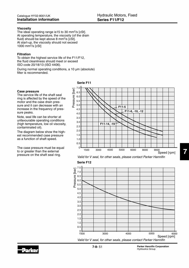
7-8- 51 Parker Hannifin CorporationHydraulics Group
Hydraulic Motors, FixedSeries F11/F12
Catalogue HY02-8001/UK
7
Installation information
ViscosityThe ideal operating range is15 to 30 mm2/s [cSt]. At operating temperature, the viscosity (of the drain fluid) should be kept above 8 mm2/s [cSt]. At start-up, the viscosity should not exceed 1000 mm2/s [cSt]
FiltrationTo obtain the highest service life of the F11/F12, the fluid cleanliness should meet or exceed ISO code 20/18/13 (ISO 4406). During normal operating conditions, a 10 µm (absolute) filter is recommended.
0
0.5
1.0
1.5
2.0
2.5
3.0
3.5
4.0
4.5
5.0
5.5
6.0
6.5
7.0
1500 3000 4000 5000 6000 8000 9000
F11-5
F11-6, -10, -12
F11-14, -19
0
0.5
1.0
1.5
2.0
2.5
3.0
3.5
4.0
1500 3000 4000 5000 6000
4.5
5.0
5.5
6.0
6.5
7.0
7.5
Speed [rpm]
Speed [rpm]
Serie F11
Serie F12
Pre
ssur
e [b
ar]
Pre
ssur
e [b
ar]
Case pressureThe service life of the shaft seal ring is affected by the speed of the motor and the case drain pres-sure and it can decrease with an increase in the frequency of pres-sure peaks. Note, seal life can be shorter at unfavourable operating conditions (high temperature, low oil viscosity, contaminated oil).The diagram below show the high-est recommended case pressure as a function of shaft speed.
The case pressure must be equal to or greater than the external pressure on the shaft seal ring.
ValidforVseal,forotherseals,pleasecontactParkerHannifin
ValidforVseal,forotherseals,pleasecontactParkerHannifin

7-8- 52 Parker Hannifin CorporationHydraulics Group
Hydraulic Motors, FixedSeries F11/F12
Catalogue HY02-8001/UK
F12_ports.epsLeif A./020204
Port CPort E(F12-110 and -125)
Port D
Drain flow
Flushing flow (when required)
Spring loaded check valve0.5 bar
Drain flow
Case drain connectionsSeries F11/F12 have two drain ports, C and D, while F12-110 and -125 have an additional port, E.The uppermost drain port (such as port C in the illustra-tion below) should always be utilized.
In mounting positions such as 'shaft up' (below) a spring loaded check valve should be installed in the drain line in order to insure a sufficiently high oil level in the case.Preferably, the drain line should be connected directly to the reservoir.
Before start-upMake sure the F11/F12 case as well as the entire hydraulic system is filled with a recommended fluid.The internal leakage, especially at low operating pres-sures, is notsufficient to provide lubrication at start-up.
NOTE:- To avoid cavitation and obtain a low noise level as well as reduced heat generation, tubes, hoses and fittings must be adequately dimensioned.
- Preferably, the suction line flow speed should be 0.5 to 1 m/s, and pressure line flow speeds 3 to 5 m/s.
Installation information