hydraulic hose - Bridgestone Corporation hose - Bridgestone Corporation
86
Transcript of hydraulic hose - Bridgestone Corporation hose - Bridgestone Corporation

■Bridgestone Products (hereinafter “Products”) are the part of the engineered systems which are manufactured by Bridgestone and must be assembled and used on the basis of Bridgestone’s instructions, processes and specifications.
■ Failure to follow the warnings set forth on the Products or in this catalog may result in serious injury or death. In the event users fail to follow usage instructions or specifications, which Bridgestone stipulates in the catalog, Bridgestone neither guarantees the performance of the Products nor is responsible for any other product-related failures/defects.
■ Bridgestone disclaims any responsibilities or liabilities for any components in the engineered system which are not designed, engineered or produced by Bridgestone.
■ Bridgestone is not responsible for the performance of the Products assembled by others in a manner which does not conform to Bridgestone instructions, processes or specifications.
■Warning indicates that failure to comply with the instructions may cause personal injury or death.
■Caution indicates that failure to comply with the instructions may cause personal injury or property damage.
DISTRIBUTION OF INFORMATIONBridgestone widely distributes the Products and usage information to distributors, sellers and users.
This information is also available on Bridgestone’s website, (www.bridgestone.com/products/diversified/hose). However, we also rely on the sellers or distributors of the Products to provide a copy of safety or usage information, including warnings and precautions to all end users.
It is imperative to read these warnings and precautions before selecting and utilizing the Products.
Warning Caution
C o n t e n t s
12
3~456
7~1011
11~131415
16~1718~1920~25
2626~2829~3233~3940~4445~47
484950
50~5152~5657~6162~6364~6566~6970~7374~76
777879808182
ContentsPrecautionsSymbolsHow to OrderThread IdentificationHose SummaryOKEPAPFHQ35 / CQ36 / SQ28EQSAE / DINSpecial Application Rubber HosesCouplings
AS / LS / UT/ UN / LCUL / UXUB / UZUB / UZ / HW / KN / KD / EX EA / EC / EK / GA / GB / UF / UG / KH
PASSTAGE LINESpecial Application Plastic HosesCouplings
CY / CW / JG / JY / SG / SH / SY / UYBridgestone SELFITBridgestone Primo LineAdaptersSplit FlangesBI - CouplerSwivel JointsAccessories for ProtectionHow to calculate Hose Exposed LengthHose Assembly InstallationRelational Table of Flow Rate / Velocity / Hose SizeTightening TorqueCertificate of Compliance with the Marine StandardCrimping Machine <UNICRIMP>
1

Maximum Working Pressure
1.5MPa220PSI
PA01I.D.
PA0104*PA0106*PA0108*
Catalog Code
1/43/81/2
6.39.5
12.7
inch mmO.D.
0.550.690.83
14.017.421.2
inch mm
220 1.5
psi MPaMax.W.P.
870 6.0
psi MPaMin.B.P.
2.172.563.54
556590
inch mmMin.B.R.
0.100.160.19
150240280
lbs/ft g/mWeight Reinforcement
4C AS/26UL/29
AS/26UL/29
Factory-assembled UNICRIMP-crimpedCompatible coupling/relevant page
For Safety’s sake Be sure to read the following before use.
Proper usage1
Preventive maintenance3
Storage4
Warning Severe personal injury or death may result if these instructions are not followed.
Caution Personal injury or property damage may result if these instructions are not followed.
●Do not touch a pressurized hydraulic hose assembly with any part of your body.If hoses, couplings or accessories are broken, and a fluid touches the skin, even if no pain is felt, a serious injury including burns may be caused. In case of JAT/JAM series, be sure to use safety chains. Use of plastic hose guards will help a person avoid injury.
●System working pressure should not exceed the rated working pressure of the hose assembly.Exceeding the rated working pressure of the hose may result in the hose bursting or hose coupling blow-off.Follow the maximum working pressure ratings listed in this catalog.
●Use compatible hydraulic fluidThe use of an incompatible hydraulic fluid will deteriorate the inner tube and the reinforcement resulting in the hose bursting or coupling hose coupling blow-off.
●Protect hose from abrasions.If the hose reinforcement is exposed, it is susceptible to rust and accelerated damage leading to serious failure like hose burst. If it is found, replace with a new one.
●Avoid applications where the hose is or will be twisted or pulled.Twisting or stretching a hydraulic hose under pressure may result in hose bursting or hose coupling blow-off.If it is found, replace with a new one, then install a live swivel joint.
●Do not snap the hose.Snapping and deforming will lead to hose burst, leakage, and hose coupling blow-off. If found, replace with a new one.
●Do not apply an electrical current to a hose assembly.Electrifying a hose may lead to a hose failure or an electric shock.
●Tighten hose assemblies to the recommended torque.If tightening is improper, there are possibilities of leakage, connection portion breakage, and separation. Be sure to apply the recommended torque by using a torque spanner. In case of over torque, replace with a new one. In case of under torque, retighten with the recommended torque ( page 82 ).
●Avoid the usage exceeding the minimum bending radiusThe usage exceeding the minimum bending radius may cause hose burst and leakage. Be sure to follow the specified minimum bending radius.
●Avoid excessive vibrationThe usage excessive vibration may cause leakage and hose coupling blow-off by fatigue.
●Avoid the usage exceeding applicable temperatureThe usage exceeding applicable temperature may cause leakage and hose coupling blow-off.
●Avoid vacuum pressure (except for suction hose)Excessive vacuum pressure may result in the inner tube damage which leads to hose failure.
●Avoid submerging hose assemblies in water or any other liquid.Hose assemblies submerged in water are exposed to external pressure which will reduce the service life of a hose and/or have bad effect on hose assembly performance.
●Remove all air from hydraulic hose assemblies.Air may cause damage to the inner tube which will lead to hose failure.
●Follow minimum hose exposed lengthFollow minimum hose exposed length. Improper length may reult in inferior performance to catalog specification.
●Never repair or rework a hose assembly.Old or used hose assemblies do not have the same physical characteristics as a new hose and cannot be used.Old hoses or damaged hoses should be replaced with new one, and should not be repaired or reworked.
●Do not use for food or drinking water, since the hose is intended for industrial use.
Before use, check for the following conditions. If any are found, replace with a new part.Physical damage, blister, exposed reinforcement, kinking, hose coupling blow-off, leakage etc.
Warranty period is impulse cycle number or each specified period, whichever comes earlier (Refer to pages 7 to 10).
Warranty period 2
- Cap the couplings or hose cut ends- Keep out of direct sunlight- Do not expose to corrosive gas, oil or chemicals- Store in dark and dry place at the temperature between -10℃ and + 40℃ (14℉ to 104℉)
Bridgestone Hydraulic hose, couplings, and accessories are developed for hydraulic components. Follow each product’s application and specification.Avoid hose burst, leakage, and other dangers by following important steps.
This catalog shows the product specifications in the format below so you can select the correct product for your needs and prevent the risk of danger.
Temperature Range : ambient Permissible temperatures of ambient environment for the hose
Temperature Range: fluidPermissible temperatures of fluid flowing through the hose
Compatible Fluid Fluid applicable to the hoseInner Tube
Inner part of the hose, which comes into direct contact with the fluidThe specifications show the materials for this part.
Outer CoverOuter part of the hose, which is i n t e n d e d t o p ro t e c t i t s reinforcingThe specifications show the materials for this part.*The color of this cover is black unless otherwise specified.
[ExampleSpecifications of Hoses]
●Compatible Fluid / Mineral Hydraulic Oil●Temperature Range: fluid / −40°C to 100°C / −40°F to 212°F●Temperature Range: ambient / −40°C to 70°C / −40°F to 158°F●Inner Tube / Oil-resistant synthetic rubber●Outer Cover / Weather-resistant synthetic rubber
PressurePressure shown in psi/MPa units
I.D.・O.D.Inside and Outside diameters of the hose
Coupling SeriesSeries of couplings that are crimped either at a factory or with UNICRIMP. The number after “/” indicates the number of the page that describes the applicable series of couplings.*Crimping the couplings may be impossible depending on the type of UNICRIMP used.
Min.B.R.Minimum bending radius that can be achieved without performance degradation. This radius is specified on the inside surface of the bend area.
Min.B.P.Pressure that the hose should withstand without problems such as coupling detachment, hose burst ing, and flu id leaking from the crimped part when the hose is subjected to water or oil pressure.
Max.W.P.Maximum usable working pressure
ReinforcementFibers or wires woven or spirally wrapped around an inner tube to maintain hose p e r f o r m a n c e . T h e spec ificat ions show the structure of the reinforcing.
Catalog CodeWhen ordering a product, specify its catalog number.*For details, refer to page 5.
WeightApproximate Weight of Hose
HoseHoses are flexible tubes designed to carry fluid from one location to another or to convey pressure. Typically, they include rubber hoses ( , , etc.) and plastic hoses ( ,etc.).
2
Precautions

Maximum Working Pressure
1.5MPa220PSI
PA01I.D.
PA0104*PA0106*PA0108*
Catalog Code
1/43/81/2
6.39.5
12.7
inch mmO.D.
0.550.690.83
14.017.421.2
inch mm
220 1.5
psi MPaMax.W.P.
870 6.0
psi MPaMin.B.P.
2.172.563.54
556590
inch mmMin.B.R.
0.100.160.19
150240280
lbs/ft g/mWeight Reinforcement
4C AS/26UL/29
AS/26UL/29
Factory-assembled UNICRIMP-crimpedCompatible coupling/relevant page
For Safety’s sake Be sure to read the following before use.
Proper usage1
Preventive maintenance3
Storage4
Warning Severe personal injury or death may result if these instructions are not followed.
Caution Personal injury or property damage may result if these instructions are not followed.
●Do not touch a pressurized hydraulic hose assembly with any part of your body.If hoses, couplings or accessories are broken, and a fluid touches the skin, even if no pain is felt, a serious injury including burns may be caused. In case of JAT/JAM series, be sure to use safety chains. Use of plastic hose guards will help a person avoid injury.
●System working pressure should not exceed the rated working pressure of the hose assembly.Exceeding the rated working pressure of the hose may result in the hose bursting or hose coupling blow-off.Follow the maximum working pressure ratings listed in this catalog.
●Use compatible hydraulic fluidThe use of an incompatible hydraulic fluid will deteriorate the inner tube and the reinforcement resulting in the hose bursting or coupling hose coupling blow-off.
●Protect hose from abrasions.If the hose reinforcement is exposed, it is susceptible to rust and accelerated damage leading to serious failure like hose burst. If it is found, replace with a new one.
●Avoid applications where the hose is or will be twisted or pulled.Twisting or stretching a hydraulic hose under pressure may result in hose bursting or hose coupling blow-off.If it is found, replace with a new one, then install a live swivel joint.
●Do not snap the hose.Snapping and deforming will lead to hose burst, leakage, and hose coupling blow-off. If found, replace with a new one.
●Do not apply an electrical current to a hose assembly.Electrifying a hose may lead to a hose failure or an electric shock.
●Tighten hose assemblies to the recommended torque.If tightening is improper, there are possibilities of leakage, connection portion breakage, and separation. Be sure to apply the recommended torque by using a torque spanner. In case of over torque, replace with a new one. In case of under torque, retighten with the recommended torque ( page 82 ).
●Avoid the usage exceeding the minimum bending radiusThe usage exceeding the minimum bending radius may cause hose burst and leakage. Be sure to follow the specified minimum bending radius.
●Avoid excessive vibrationThe usage excessive vibration may cause leakage and hose coupling blow-off by fatigue.
●Avoid the usage exceeding applicable temperatureThe usage exceeding applicable temperature may cause leakage and hose coupling blow-off.
●Avoid vacuum pressure (except for suction hose)Excessive vacuum pressure may result in the inner tube damage which leads to hose failure.
●Avoid submerging hose assemblies in water or any other liquid.Hose assemblies submerged in water are exposed to external pressure which will reduce the service life of a hose and/or have bad effect on hose assembly performance.
●Remove all air from hydraulic hose assemblies.Air may cause damage to the inner tube which will lead to hose failure.
●Follow minimum hose exposed lengthFollow minimum hose exposed length. Improper length may reult in inferior performance to catalog specification.
●Never repair or rework a hose assembly.Old or used hose assemblies do not have the same physical characteristics as a new hose and cannot be used.Old hoses or damaged hoses should be replaced with new one, and should not be repaired or reworked.
●Do not use for food or drinking water, since the hose is intended for industrial use.
Before use, check for the following conditions. If any are found, replace with a new part.Physical damage, blister, exposed reinforcement, kinking, hose coupling blow-off, leakage etc.
Warranty period is impulse cycle number or each specified period, whichever comes earlier (Refer to pages 7 to 10).
Warranty period 2
- Cap the couplings or hose cut ends- Keep out of direct sunlight- Do not expose to corrosive gas, oil or chemicals- Store in dark and dry place at the temperature between -10℃ and + 40℃ (14℉ to 104℉)
Bridgestone Hydraulic hose, couplings, and accessories are developed for hydraulic components. Follow each product’s application and specification.Avoid hose burst, leakage, and other dangers by following important steps.
This catalog shows the product specifications in the format below so you can select the correct product for your needs and prevent the risk of danger.
Temperature Range : ambient Permissible temperatures of ambient environment for the hose
Temperature Range: fluidPermissible temperatures of fluid flowing through the hose
Compatible Fluid Fluid applicable to the hoseInner Tube
Inner part of the hose, which comes into direct contact with the fluidThe specifications show the materials for this part.
Outer CoverOuter part of the hose, which is i n t e n d e d t o p ro t e c t i t s reinforcingThe specifications show the materials for this part.*The color of this cover is black unless otherwise specified.
[ExampleSpecifications of Hoses]
●Compatible Fluid / Mineral Hydraulic Oil●Temperature Range: fluid / −40°C to 100°C / −40°F to 212°F●Temperature Range: ambient / −40°C to 70°C / −40°F to 158°F●Inner Tube / Oil-resistant synthetic rubber●Outer Cover / Weather-resistant synthetic rubber
PressurePressure shown in psi/MPa units
I.D.・O.D.Inside and Outside diameters of the hose
Coupling SeriesSeries of couplings that are crimped either at a factory or with UNICRIMP. The number after “/” indicates the number of the page that describes the applicable series of couplings.*Crimping the couplings may be impossible depending on the type of UNICRIMP used.
Min.B.R.Minimum bending radius that can be achieved without performance degradation. This radius is specified on the inside surface of the bend area.
Min.B.P.Pressure that the hose should withstand without problems such as coupling detachment, hose burst ing, and flu id leaking from the crimped part when the hose is subjected to water or oil pressure.
Max.W.P.Maximum usable working pressure
ReinforcementFibers or wires woven or spirally wrapped around an inner tube to maintain hose p e r f o r m a n c e . T h e spec ificat ions show the structure of the reinforcing.
Catalog CodeWhen ordering a product, specify its catalog number.*For details, refer to page 5.
WeightApproximate Weight of Hose
HoseHoses are flexible tubes designed to carry fluid from one location to another or to convey pressure. Typically, they include rubber hoses ( , , etc.) and plastic hoses ( ,etc.).
3
Symbols
R0.670.750.870.871.181.181.421.81
1719222230303646
0.510.590.710.710.790.790.870.99
13151818202022
25.2
1.972.282.522.523.073.353.664.80
50586464788593
122
0.110.190.280.280.490.630.951.91
5085
125125220285430865
1/43/81/21/23/43/41
1 1/4
UZ04RUB06RUB08RUZ08RUB1012RUB12RUB16RUZ20R
Catalog CodeThread
WeightYinch mm inch mm inch mm lbs g
A
A
R Y(HEX)
Male British Tapered Pipe Thread(BSPT)
(L)
(L) Hose inside diameter connected to cou-plings and thread size in 1/16 of an inch.(08 = 8/16 = 1/2inch)・In case of jump size coupling.
For Example, if hose ID is 5/8”(=10/16”) and thread size is 3/4”(=12/16”), UA1012R is the catalog number.
Type of hose(hose series No.)
Recommended workingpressure(07=7.0MPa)
Hose inside diameter in 1/16of an inch.(04=4/16=1/4 inch)
Coupling Series.
HOSE Example of hose catalog numbers
08
Thread size(08=8/16"=1/2")
80 01 RG 08Type of adaptor Combination of thread type
In this case“R” & “G”
COUPLING
Adaptor
PA 07
Type of hose(hose series No.)
Hose inside diameter in 1/16of an inch.(08=8/16=1/2 inch)
R1T 0804
UB R
Adaptor
(Pressure-rated hose) (SAE hose)
Crimping Portion(coupling series)Thread
Type of thread.
Bent tube ends and flange head couplings can be oriented at different angles to one another and must be specified when ordering. As per the illustration right, the orientation angle is measured starting from either end as the far end, clockwise to the near end. In the case of illustration right, the orientation angle is 225°.
Please refer to the figures below when you specify the assembly length.
【HOSE LENGTH(L)】 【Orientation Angle】
L
L L
225°
L
FAREND
NEAREND
Selecting the proper hose
Please check below points.Hose Length (Please refer[Hose Length(L)]above and“Hose exposed length calculation”in this catalog)Orientation angle (Please refer above[Orientation Angle])Application and Environmental Conditions.Minimum bending Radius.Drawing.
Fluid to be used.Delivery (flow rate and velocity) or Hose ID (Please refer “Pressure Loss”in this catalog)Maximum working pressure.Fluid and ambient Temperature.Thread type.
① To order assembled hoses, specify the following (typical examples of data):Hose
catalog codePA2108
× Hose length Hosecatalog code × Hose length Hose
catalog code × Hose length
×1,000(L)
Coupling atone endUZ08R
Coupling atthe other end
UZ08C
Hose adapter
8002RG08
No.
10
②To order hoses and fittings separately, specify the following:
PA2108 ×60,000(L)
Fittingscatalog code
UZ08RUZ08R
8002RG08
No. of pieces
101010
orPA2108 ×30,000(L)
No.
2
Ordering Method
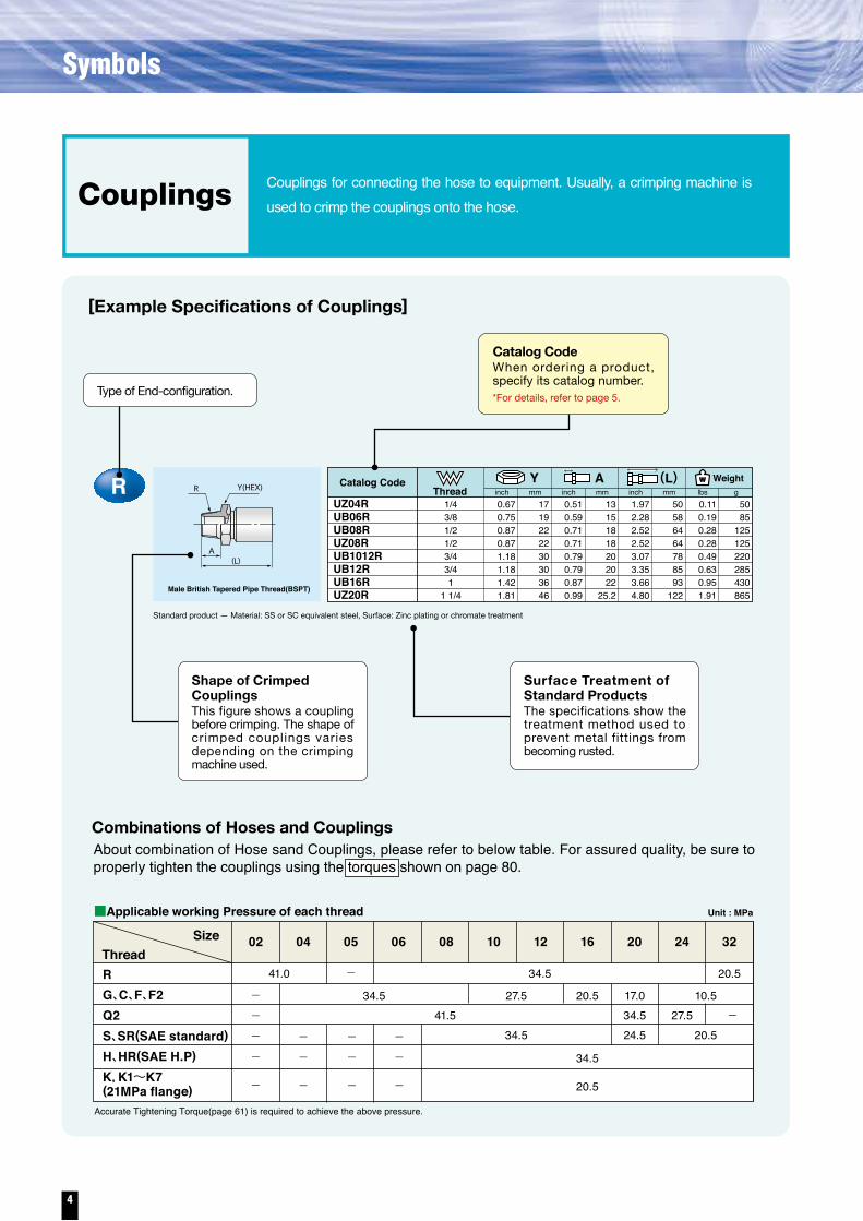
Standard product — Material: SS or SC equivalent steel, Surface: Zinc plating or chromate treatment
ThreadSize
RG、C、F、F2Q2S、SR(SAE standard)H、HR(SAE H.P)K,K1~K7(21MPa flange)
41.0
Unit : MPa■Applicable working Pressure of each thread
02 04 05 06 08 10 12 16 20 24 32
34.5 20.5-
-
34.5
34.5 24.534.5
20.5
34.5----
-
--
-
--
-
--
-
27.5 20.5 17.0 10.541.5 27.5
20.5
[Example Specifications of Couplings]
Combinations of Hoses and Couplings
Couplings for connecting the hose to equipment. Usually, a crimping machine is used to crimp the couplings onto the hose.
Type of End-configuration.
About combination of Hose sand Couplings, please refer to below table. For assured quality, be sure to properly tighten the couplings using the torques shown on page 80.
Couplings
Accurate Tightening Torque(page 61) is required to achieve the above pressure.
■Below are examples of the catalog code shown in this catalog.
Shape of Crimped CouplingsThis figure shows a coupling before crimping. The shape of crimped couplings varies depending on the crimping machine used.
Surface Treatment of Standard ProductsThe specifications show the treatment method used to prevent metal fittings from becoming rusted.
Catalog CodeWhen ordering a product, specify its catalog number.*For details, refer to page 5.
4
Symbols

R0.670.750.870.871.181.181.421.81
1719222230303646
0.510.590.710.710.790.790.870.99
13151818202022
25.2
1.972.282.522.523.073.353.664.80
50586464788593
122
0.110.190.280.280.490.630.951.91
5085
125125220285430865
1/43/81/21/23/43/41
1 1/4
UZ04RUB06RUB08RUZ08RUB1012RUB12RUB16RUZ20R
Catalog CodeThread
WeightYinch mm inch mm inch mm lbs g
A
A
R Y(HEX)
Male British Tapered Pipe Thread(BSPT)
(L)
(L) Hose inside diameter connected to cou-plings and thread size in 1/16 of an inch.(08 = 8/16 = 1/2inch)・In case of jump size coupling.
For Example, if hose ID is 5/8”(=10/16”) and thread size is 3/4”(=12/16”), UA1012R is the catalog number.
Type of hose(hose series No.)
Recommended workingpressure(07=7.0MPa)
Hose inside diameter in 1/16of an inch.(04=4/16=1/4 inch)
Coupling Series.
HOSE Example of hose catalog numbers
08
Thread size(08=8/16"=1/2")
80 01 RG 08Type of adaptor Combination of thread type
In this case“R” & “G”
COUPLING
Adaptor
PA 07
Type of hose(hose series No.)
Hose inside diameter in 1/16of an inch.(08=8/16=1/2 inch)
R1T 0804
UB R
Adaptor
(Pressure-rated hose) (SAE hose)
Crimping Portion(coupling series)Thread
Type of thread.
Bent tube ends and flange head couplings can be oriented at different angles to one another and must be specified when ordering. As per the illustration right, the orientation angle is measured starting from either end as the far end, clockwise to the near end. In the case of illustration right, the orientation angle is 225°.
Please refer to the figures below when you specify the assembly length.
【HOSE LENGTH(L)】 【Orientation Angle】
L
L L
225°
L
FAREND
NEAREND
Selecting the proper hose
Please check below points.Hose Length (Please refer[Hose Length(L)]above and“Hose exposed length calculation”in this catalog)Orientation angle (Please refer above[Orientation Angle])Application and Environmental Conditions.Minimum bending Radius.Drawing.
Fluid to be used.Delivery (flow rate and velocity) or Hose ID (Please refer “Pressure Loss”in this catalog)Maximum working pressure.Fluid and ambient Temperature.Thread type.
① To order assembled hoses, specify the following (typical examples of data):Hose
catalog codePA2108
× Hose length Hosecatalog code × Hose length Hose
catalog code × Hose length
×1,000(L)
Coupling atone endUZ08R
Coupling atthe other end
UZ08C
Hose adapter
8002RG08
No.
10
②To order hoses and fittings separately, specify the following:
PA2108 ×60,000(L)
Fittingscatalog code
UZ08RUZ08R
8002RG08
No. of pieces
101010
orPA2108 ×30,000(L)
No.
2
Ordering Method
Standard product — Material: SS or SC equivalent steel, Surface: Zinc plating or chromate treatment
ThreadSize
RG、C、F、F2Q2S、SR(SAE standard)H、HR(SAE H.P)K,K1~K7(21MPa flange)
41.0
Unit : MPa■Applicable working Pressure of each thread
02 04 05 06 08 10 12 16 20 24 32
34.5 20.5-
-
34.5
34.5 24.534.5
20.5
34.5----
-
--
-
--
-
--
-
27.5 20.5 17.0 10.541.5 27.5
20.5
[Example Specifications of Couplings]
Combinations of Hoses and Couplings
Couplings for connecting the hose to equipment. Usually, a crimping machine is used to crimp the couplings onto the hose.
Type of End-configuration.
About combination of Hose sand Couplings, please refer to below table. For assured quality, be sure to properly tighten the couplings using the torques shown on page 80.
Couplings
Accurate Tightening Torque(page 61) is required to achieve the above pressure.
■Below are examples of the catalog code shown in this catalog.
Shape of Crimped CouplingsThis figure shows a coupling before crimping. The shape of crimped couplings varies depending on the crimping machine used.
Surface Treatment of Standard ProductsThe specifications show the treatment method used to prevent metal fittings from becoming rusted.
Catalog CodeWhen ordering a product, specify its catalog number.*For details, refer to page 5.
5
How to Order

R C CF
S/H K Q2
Female British Parallel Pipe Thread Male 30°Seat (BSPOR)
Female Japanese Industrial PipeThread (JIS) Female 30°Seat
Female O-Ring Face SealJIS 20.5Mpa Flange
Male British TaperedPipe Thread (BSPT)
Flange HeadS : CODE 61 Flange / H : CODE 62 Flange
Male British Parallel PipeThread (BSPP)G
Q2C7 F2 JIC 37° FemaleFemale O-Ring Face Seal
●The following non-standard products are also available. For details, contact us.
R PF
30゜
PF
30゜
PF
30゜
F4 Female MetricThread Female 30°Seat
※Komatsu Female 30°Seat
M(P=1.5)
30゜
J3 SAE 45° Male
UNF
45°
R1 J2 A1
D1 F3
JIC 37° Male Rigid Male O-Ring Boss
SAE 45° Female
NPTF Male
Female Taper Pipe Thread
※American Pipe Thread
UNF
O-Ring Groove
A9 Male O-ring Face Seal
UNF
37゜
NPTF
NPTF
45°
UNF
CE9 Female Taper Pipe Thread
NPTF
* Coupling materials are carbon steel with zinc plating* As for PrimoLine series, coupling type is special one. Please see PrimoLine page (page 59).*Refer to page 26 to 47 for rubber hoses, page 50 to 51 for plastic hoses in detail
UNF
UNF
37゜
11 1412~13
Series
InsideDiameter
1.5
1.51.51.51.51.5
3.24.86.37.99.5
12.715.919.025.431.838.150.863.576.2
1/83/16
1/45/163/81/25/83/4
11-1/41-1/2
22-1/2
3
0203040506081012162024324048
1.5
1.51.5
3.5
3.53.53.53.53.53.53.5
7.0
7.07.07.07.07.07.07.07.0
10.5
10.510.510.510.510.510.510.510.5
14.0
14.014.014.014.014.014.014.014.0
17.0
17.017.017.017.017.0
20.5
20.520.520.520.520.520.520.520.5
27.5
27.527.527.527.527.527.527.527.5
34.5
34.534.534.534.534.534.534.534.5
7.0
7.07.0
14.0
14.014.0
17.0
17.017.0
20.5
20.520.520.520.520.5
24.5
24.524.5
27.5
27.527.5
Low-pressurerubberhoses
Standard Rubber Hoses Slim Rubber Hoses
mm Code Type OKE PA01 PA03 PA07 PA10 PA14 PA17 PA21 PA28 PA35 PF07 PF14 PF17 PF21 PFW PFHinch
*For information about other couplings, contact us. For information about adapters, refer to pages 62 and 63.
HOSE
C1 Female NPSM Male 30°Seat
NPSM
30゜
D Female Taper Pipe Thread
Rc
●The coupling threads shown below are available. They comply with the JIS and ISO standards. The types of coupling threads are designated “R,” “F,” etc. These are included in the catalog numbers.
●A series of couplings is available for each hose. The standard coupling threads differ for each series of couplings. For details, refer to the coupling specifications.
●Standard products are made from SS or SC equivalent steel processed with a surface treatment (zinc plating or chromate treatment). Products made from stainless steel or brass are also available. For details, contact us.
For paint sprays
3× 4× Maximum working pressure
OKE
Maxim
um w
orking pressure MPa
26~28●●●●●●●
●●●
●●
Relevant pageRFCG
CRS
SRH
HRK~K4
K~K3RF4F2
F2RQQ2
Q2R
●●●●●●●
●●●
●●
26~32●●●●●●●
●●●
●●
●●●●●●●
●●●●●
●●
●●●●●●●
●●●●●
●●
●●●●●●●
●●●●●
●●
32~44●●●●●●●
●●●●●
●●
●●●●●●●
●●●●●
●●
●●●●●●●●●
●●●
●●
●●●●●●●●●
●●●
●●
●●●●●●●
●●●●●
●●
●●●●●●●
●●●●●
●●
●●●●●●●
●●●●●
●●
33~39●●●●●●●
●●●●●
●●
●●●●●●●
●●●●●
●●
●●●●●●●
●●●●●
●●
OKE PA01 PA03 PA07 PA10 PA14 PA17 PA21 PA28 PA35 PF07 PF14 PF17 PF21 PFW PFHHose typeCOUPLING
Coupling thread type
Relevant page
Minimum burst pressure(MPa)
Fluid temperature(ºC)
Compatible fluid
Uses and features
Warranty period
Recommendedambient temperature
(ºC)
−40 to+100(oil)0 to +50(water)
−40 to +60(water-glycol)
−40 to +100(Oil)−40 to +60
(Water Glycol)
−40 to +70 (Oil)−40 to +60
(Water Glycol)
−40 to+100
−40 to +70
Mineral hydraulic oil
Ordinary hydraulic piping
1 year
400,000200,000
Abrasion-resistantslim type for ordinary hydraulic piping
Mineral hydraulic oil Water Glycol
−40 to +70 (oil)0 to +70 (water)
−40 to +60(water-glycol)
Mineral hydraulic oil, water, water-glycol
Low-pressure,lightweight
Period1 year for
oil hoses or6 months forwater hoses
No. oftimes used
*Warranty is effective until the predetermined usage period expires or the impulse cycle count reaches the predetermined value, whichever occurs first. (The impulse cycle count refers to the number of times the hose has been pressurized under the specified hose usage conditions.)
30°
G
Bend types also available
Bend types also available
Bend types also available
Bend types also available
Bend types also available Bend types also available
Bend types also available
DIN Metric Female Thread(with Male 12º Seat O-ring Groove)MQ4
12°
( L )
M
X
φD
Y
Bend types also available
DIN Metric Female Thread(with Male 12º Seat O-ring Groove)MQ5
12°
( L )
M
X
φD
Y
Bend types also available
A
UNF
φB
(L)
Y
6
Thread Identification

R C CF
S/H K Q2
Female British Parallel Pipe Thread Male 30°Seat (BSPOR)
Female Japanese Industrial PipeThread (JIS) Female 30°Seat
Female O-Ring Face SealJIS 20.5Mpa Flange
Male British TaperedPipe Thread (BSPT)
Flange HeadS : CODE 61 Flange / H : CODE 62 Flange
Male British Parallel PipeThread (BSPP)G
Q2C7 F2 JIC 37° FemaleFemale O-Ring Face Seal
●The following non-standard products are also available. For details, contact us.
R PF
30゜
PF
30゜
PF
30゜
F4 Female MetricThread Female 30°Seat
※Komatsu Female 30°Seat
M(P=1.5)
30゜
J3 SAE 45° Male
UNF
45°
R1 J2 A1
D1 F3
JIC 37° Male Rigid Male O-Ring Boss
SAE 45° Female
NPTF Male
Female Taper Pipe Thread
※American Pipe Thread
UNF
O-Ring Groove
A9 Male O-ring Face Seal
UNF
37゜
NPTF
NPTF
45°
UNF
CE9 Female Taper Pipe Thread
NPTF
* Coupling materials are carbon steel with zinc plating* As for PrimoLine series, coupling type is special one. Please see PrimoLine page (page 59).*Refer to page 26 to 47 for rubber hoses, page 50 to 51 for plastic hoses in detail
UNF
UNF
37゜
11 1412~13
Series
InsideDiameter
1.5
1.51.51.51.51.5
3.24.86.37.99.5
12.715.919.025.431.838.150.863.576.2
1/83/16
1/45/163/81/25/83/4
11-1/41-1/2
22-1/2
3
0203040506081012162024324048
1.5
1.51.5
3.5
3.53.53.53.53.53.53.5
7.0
7.07.07.07.07.07.07.07.0
10.5
10.510.510.510.510.510.510.510.5
14.0
14.014.014.014.014.014.014.014.0
17.0
17.017.017.017.017.0
20.5
20.520.520.520.520.520.520.520.5
27.5
27.527.527.527.527.527.527.527.5
34.5
34.534.534.534.534.534.534.534.5
7.0
7.07.0
14.0
14.014.0
17.0
17.017.0
20.5
20.520.520.520.520.5
24.5
24.524.5
27.5
27.527.5
Low-pressurerubberhoses
Standard Rubber Hoses Slim Rubber Hoses
mm Code Type OKE PA01 PA03 PA07 PA10 PA14 PA17 PA21 PA28 PA35 PF07 PF14 PF17 PF21 PFW PFHinch
*For information about other couplings, contact us. For information about adapters, refer to pages 62 and 63.
HOSE
C1 Female NPSM Male 30°Seat
NPSM
30゜
D Female Taper Pipe Thread
Rc
●The coupling threads shown below are available. They comply with the JIS and ISO standards. The types of coupling threads are designated “R,” “F,” etc. These are included in the catalog numbers.
●A series of couplings is available for each hose. The standard coupling threads differ for each series of couplings. For details, refer to the coupling specifications.
●Standard products are made from SS or SC equivalent steel processed with a surface treatment (zinc plating or chromate treatment). Products made from stainless steel or brass are also available. For details, contact us.
For paint sprays
3× 4× Maximum working pressure
OKE
Maxim
um w
orking pressure MPa
26~28●●●●●●●
●●●
●●
Relevant pageRFCG
CRS
SRH
HRK~K4
K~K3RF4F2
F2RQQ2
Q2R
●●●●●●●
●●●
●●
26~32●●●●●●●
●●●
●●
●●●●●●●
●●●●●
●●
●●●●●●●
●●●●●
●●
●●●●●●●
●●●●●
●●
32~44●●●●●●●
●●●●●
●●
●●●●●●●
●●●●●
●●
●●●●●●●●●
●●●
●●
●●●●●●●●●
●●●
●●
●●●●●●●
●●●●●
●●
●●●●●●●
●●●●●
●●
●●●●●●●
●●●●●
●●
33~39●●●●●●●
●●●●●
●●
●●●●●●●
●●●●●
●●
●●●●●●●
●●●●●
●●
OKE PA01 PA03 PA07 PA10 PA14 PA17 PA21 PA28 PA35 PF07 PF14 PF17 PF21 PFW PFHHose typeCOUPLING
Coupling thread type
Relevant page
Minimum burst pressure(MPa)
Fluid temperature(ºC)
Compatible fluid
Uses and features
Warranty period
Recommendedambient temperature
(ºC)
−40 to+100(oil)0 to +50(water)
−40 to +60(water-glycol)
−40 to +100(Oil)−40 to +60
(Water Glycol)
−40 to +70 (Oil)−40 to +60
(Water Glycol)
−40 to+100
−40 to +70
Mineral hydraulic oil
Ordinary hydraulic piping
1 year
400,000200,000
Abrasion-resistantslim type for ordinary hydraulic piping
Mineral hydraulic oil Water Glycol
−40 to +70 (oil)0 to +70 (water)
−40 to +60(water-glycol)
Mineral hydraulic oil, water, water-glycol
Low-pressure,lightweight
Period1 year for
oil hoses or6 months forwater hoses
No. oftimes used
*Warranty is effective until the predetermined usage period expires or the impulse cycle count reaches the predetermined value, whichever occurs first. (The impulse cycle count refers to the number of times the hose has been pressurized under the specified hose usage conditions.)
30°
G
Bend types also available
Bend types also available
Bend types also available
Bend types also available
Bend types also available Bend types also available
Bend types also available
DIN Metric Female Thread(with Male 12º Seat O-ring Groove)MQ4
12°
( L )
M
X
φD
Y
Bend types also available
DIN Metric Female Thread(with Male 12º Seat O-ring Groove)MQ5
12°
( L )
M
X
φD
Y
Bend types also available
A
UNF
φB
(L)
Y
7
Hose Summary

●
●
●
●
●●
●●
●●
●●
●●●
●
●●
●●
●●●●
●●●●
●●●●
●●●●
●●●●
●●●●●●●
●●
●●●●●●●●●●●
●●●●●●●●●●●
●●●●●●●●●●●
●●●●●●●
●●●
●●
SAE / DIN Hoses●Hose Available Only
16~17 18~19
Series
InsideDiameter
17.017.017.017.017.017.0
3.24.86.37.99.5
12.715.919.025.431.838.150.863.576.2
1/83/16
1/45/163/81/25/83/4
11-1/41-1/2
22-1/2
3
0203040506081012162024324048
20.520.520.520.520.520.520.5
24.524.524.524.524.524.5
27.527.527.527.527.527.5
31.031.031.031.031.031.031.0
35.0
35.035.035.035.0
22.5
18.016.013.010.58.76.25.04.0
40.0
33.027.525.021.516.512.59.08.0
28.028.028.028.028.021.017.517.5
35.035.035.035.035.0
42.042.0
42.042.042.042.0
44.541.535.035.028.021.018.5
42.038.032.529.025.0
120°C Rubber Hoses
mm Code Type EQ17 EQ21 EQ25 EQ28 EQ31 EQ35 R1AT R2AT R12A R13A R15A 4SP 4SHinch
*For information about other couplings, contact us. For information about adapters, refer to pages 62 and 63.
5× Maximum working pressure
SAE Series DIN Series
Maxim
um w
orking pressure MPa
●●●●●●●●●●●●●●
●●
Relevant pageRFCG
CRS
SRH
HRK~K4
K~K3RF4F2
F2RQQ2
Q2R
●●●●●●●●●●●●●●
●●
33~44●●●●●●●●●
●●●
●●
●●●●●●●●●
●●●
●●
●●●●●●●●●
●●●
●●
●●●●●●●●●
●●●
●●
ーーーーーーーーーーーーーーーーー
Hose typeCOUPLING
Coupling thread type
Relevant page
Minimum burst pressure(MPa)
Fluid temperature(ºC)
Compatible fluid
Uses and features
Warranty period
Recommendedambient temperature
(ºC)
-40 to +120
160MPa
-40 to +70*It does not guarantee the use of constantly 80℃
-40 to +100(-40 to +120(CQ38))
-40 to +70
Mineral hydraulic oilMineral hydraulic oil
Impulsecycle
1,200,000MSHA
ApprovedUltraHigh
Abrasion
Mineralhydraulic oil
Cleaning/green cut/
peeling
For ultra highpressure
hydraulic tools
Hotwater
Hotcleaning
Airsupply
Steamcleaning
Injection Moldong MachineSteel Plant
Heatresistance
-40 to +100 0 to +800 to +80
0 to +70
WaterCement milk
CleaningCement grouting
-40 to +100+4 to+210
-40 to+135
-40 to+100
-40 to+60 (water glycol)-40 to +100 (Mineral hydraulic oil)
0 to +60(Water, High Water Base Fluid)-40 to+70 (water glycol)
-40 to +70 (Mineral hydraulic oil)0 to +70(Water,
High Water Base Fluid)
0 to+120
-40 to+60
-40 to +70 -40 to +70-40 to +70
WaterSteamAir Mineralhydraulic oil
Maximum fluidtemperature 120°C
1 year 1 year1 year 1 year 1 year 6 months1 year 1 year 1 year
1,000,000 500,000 400,000 25,000 100,000 100,000100,0001000000*1 200,000−
−
−
− − 400,000200,000
−40 to+93(oil),0 to+50(water)
-40 to +70
Water glycolMineral hydraulic oil
Water, High Water Base Fluid
-40 to+70
-40 to+60
−40 to+70(oil),0 to+70(water)
Mineralhydraulicoil/water
Crimpingmachine
not required
Large bore, large flow volume, max.
length of 40m
Mineralhydraulic oil/Mineralengine oil
PeriodNo. of
times used*Warranty is effective until the predetermined usage period expires or the impulse cycle count reaches the predetermined value, whichever occurs first. (The impulse cycle count refers to the number of times the hose has been pressurized under the specified hose usage conditions.)
EQ17 EQ21 EQ25 EQ28 EQ31 EQ35 R1AT R2AT R12A R13A R15A 4SP 4SH
22 2320 21 24 25
Series
InsideDiameter
68.5
68.568.5
3.24.86.37.99.5
12.715.919.025.431.838.150.863.576.2
1/83/16
1/45/163/81/25/83/4
11-1/41-1/2
22-1/2
3
0203040506081012162024324048
137.0
98.098.0
3.03.03.03.0
14.0
14.014.0
14.0
14.014.0
14.014.0
20.5
20.520.5
20.520.5
20.5
20.520.52.0
2.02.0
7.07.0
2.0
2.02.0
21.0
21.021.0
21.021.021.021.021.0
21.0
21.021.021.021.021.021.021.021.0
28.0
28.028.0
28.028.028.028.028.0
3.5
3.53.5
3.53.5
4.93.0
14.010.5
20.517.0
RubberHoses
for Jacks
Rubber Hoses(lightweight, flexible)for water cleaning
Rubber Hosesfor water and cementmilk
Hoses forboth water-glycol
and mineral oil
Large-borehigh-pressure
HosesSuctionHoses
Hosesfor hot
cleaning
Hosesfor steamcleaning
Push-onHoses
AirHoses
Heat /oil-resistantHoses
mm Code Type JW70 JWM VW WA14 WARWJ WB21
WJ WB21
SA HM ACTRX21 RX28 RT21 PA03-DA JBT JBF JBSinch
*For information about other couplings, contact us. For information about adapters, refer to pages 62 and 63.
HOSEHOSE
JW・JWM VW WA・WARWJ・WB
20.5
WH21WHSA HM ACTRX・RT PA03
-DA
Maxim
um w
orking pressure MPa
Relevant pageRFCG
CRS
SRH
HRK~K4
K~K3RF4F2
F2RQQ2
Q2R
33~39,45 29~3233~4022 2326~27 4526~32,40 2533~44Hose type
COUPLING
Coupling thread type
Relevant page
Minimum burst pressure(MPa)
Fluid temperature(ºC)
Compatible fluid
Uses and features
Warranty period
Recommendedambient temperature
(ºC)
About 2×maximum
working pressure
Max. negativepressure
−0.08665MPa
About 2.5× max.working pressure
About 3× max.working pressure
About 4× max.working pressure
About 4× max.
working pressure
4× max.workingpressure
6× max.workingpressure
4× max.workingpressure
4 x max. working pressure
4× max.workingpressure 4 X max.working pressure
Mineral hydraulic oil
-40 to +100 for R1AR, R2AT, 4SP and 4SH-40 to +120 for R12A, R13A and R15A
5× max.workingpressure
3× max.workingpressure
Period 6 months3 monthsNo. of
times used
1 year (oil)/6 months (water)
*Warranty is effective until the predetermined usage period expires or the impulse cycle count reaches the predetermined value, whichever occurs first. (The impulse cycle count refers to the number of times the hose has been pressurized under the specified hose usage conditions.)*1; 400,000 for braid construction under Water and high water base fluid.
JW70 JWM VW WA14 WARSA HM ACT WH21RX28RX21 RT21 PA03-DA JBT JBF JBS
HQ35 CQ SQ28HQ CQ SQ
15
●●●●●●●●●
●●●
●●
33~39●●●●●●
●●
●●
●●
●●●●●●●●●
●●
HQ35 CQ SQ28
34.534.534.534.534.5
36.0
36.036.036.038.038.038.0
27.527.527.5
Slim Rubber Hoses
1,200,000 1,000,000 400,000
8
Hose Summary

●
●
●
●
●●
●●
●●
●●
●●●
●
●●
●●
●●●●
●●●●
●●●●
●●●●
●●●●
●●●●●●●
●●
●●●●●●●●●●●
●●●●●●●●●●●
●●●●●●●●●●●
●●●●●●●
●●●
●●
SAE / DIN Hoses●Hose Available Only
16~17 18~19
Series
InsideDiameter
17.017.017.017.017.017.0
3.24.86.37.99.5
12.715.919.025.431.838.150.863.576.2
1/83/16
1/45/163/81/25/83/4
11-1/41-1/2
22-1/2
3
0203040506081012162024324048
20.520.520.520.520.520.520.5
24.524.524.524.524.524.5
27.527.527.527.527.527.5
31.031.031.031.031.031.031.0
35.0
35.035.035.035.0
22.5
18.016.013.010.58.76.25.04.0
40.0
33.027.525.021.516.512.59.08.0
28.028.028.028.028.021.017.517.5
35.035.035.035.035.0
42.042.0
42.042.042.042.0
44.541.535.035.028.021.018.5
42.038.032.529.025.0
120°C Rubber Hoses
mm Code Type EQ17 EQ21 EQ25 EQ28 EQ31 EQ35 R1AT R2AT R12A R13A R15A 4SP 4SHinch
*For information about other couplings, contact us. For information about adapters, refer to pages 62 and 63.
5× Maximum working pressure
SAE Series DIN Series
Maxim
um w
orking pressure MPa
●●●●●●●●●●●●●●
●●
Relevant pageRFCG
CRS
SRH
HRK~K4
K~K3RF4F2
F2RQQ2
Q2R
●●●●●●●●●●●●●●
●●
33~44●●●●●●●●●
●●●
●●
●●●●●●●●●
●●●
●●
●●●●●●●●●
●●●
●●
●●●●●●●●●
●●●
●●
ーーーーーーーーーーーーーーーーー
Hose typeCOUPLING
Coupling thread type
Relevant page
Minimum burst pressure(MPa)
Fluid temperature(ºC)
Compatible fluid
Uses and features
Warranty period
Recommendedambient temperature
(ºC)
-40 to +120
160MPa
-40 to +70*It does not guarantee the use of constantly 80℃
-40 to +100(-40 to +120(CQ38))
-40 to +70
Mineral hydraulic oilMineral hydraulic oil
Impulsecycle
1,200,000MSHA
ApprovedUltraHigh
Abrasion
Mineralhydraulic oil
Cleaning/green cut/
peeling
For ultra highpressure
hydraulic tools
Hotwater
Hotcleaning
Airsupply
Steamcleaning
Injection Moldong MachineSteel Plant
Heatresistance
-40 to +100 0 to +800 to +80
0 to +70
WaterCement milk
CleaningCement grouting
-40 to +100+4 to+210
-40 to+135
-40 to+100
-40 to+60 (water glycol)-40 to +100 (Mineral hydraulic oil)
0 to +60(Water, High Water Base Fluid)-40 to+70 (water glycol)
-40 to +70 (Mineral hydraulic oil)0 to +70(Water,
High Water Base Fluid)
0 to+120
-40 to+60
-40 to +70 -40 to +70-40 to +70
WaterSteamAir Mineralhydraulic oil
Maximum fluidtemperature 120°C
1 year 1 year1 year 1 year 1 year 6 months1 year 1 year 1 year
1,000,000 500,000 400,000 25,000 100,000 100,000100,0001000000*1 200,000−
−
−
− − 400,000200,000
−40 to+93(oil),0 to+50(water)
-40 to +70
Water glycolMineral hydraulic oil
Water, High Water Base Fluid
-40 to+70
-40 to+60
−40 to+70(oil),0 to+70(water)
Mineralhydraulicoil/water
Crimpingmachine
not required
Large bore, large flow volume, max.
length of 40m
Mineralhydraulic oil/Mineralengine oil
PeriodNo. of
times used*Warranty is effective until the predetermined usage period expires or the impulse cycle count reaches the predetermined value, whichever occurs first. (The impulse cycle count refers to the number of times the hose has been pressurized under the specified hose usage conditions.)
EQ17 EQ21 EQ25 EQ28 EQ31 EQ35 R1AT R2AT R12A R13A R15A 4SP 4SH
22 2320 21 24 25
Series
InsideDiameter
68.5
68.568.5
3.24.86.37.99.5
12.715.919.025.431.838.150.863.576.2
1/83/16
1/45/163/81/25/83/4
11-1/41-1/2
22-1/2
3
0203040506081012162024324048
137.0
98.098.0
3.03.03.03.0
14.0
14.014.0
14.0
14.014.0
14.014.0
20.5
20.520.5
20.520.5
20.5
20.520.52.0
2.02.0
7.07.0
2.0
2.02.0
21.0
21.021.0
21.021.021.021.021.0
21.0
21.021.021.021.021.021.021.021.0
28.0
28.028.0
28.028.028.028.028.0
3.5
3.53.5
3.53.5
4.93.0
14.010.5
20.517.0
RubberHoses
for Jacks
Rubber Hoses(lightweight, flexible)for water cleaning
Rubber Hosesfor water and cementmilk
Hoses forboth water-glycol
and mineral oil
Large-borehigh-pressure
HosesSuctionHoses
Hosesfor hot
cleaning
Hosesfor steamcleaning
Push-onHoses
AirHoses
Heat /oil-resistantHoses
mm Code Type JW70 JWM VW WA14 WARWJ WB21
WJ WB21
SA HM ACTRX21 RX28 RT21 PA03-DA JBT JBF JBSinch
*For information about other couplings, contact us. For information about adapters, refer to pages 62 and 63.
HOSEHOSE
JW・JWM VW WA・WARWJ・WB
20.5
WH21WHSA HM ACTRX・RT PA03
-DA
Maxim
um w
orking pressure MPa
Relevant pageRFCG
CRS
SRH
HRK~K4
K~K3RF4F2
F2RQQ2
Q2R
33~39,45 29~3233~4022 2326~27 4526~32,40 2533~44Hose type
COUPLING
Coupling thread type
Relevant page
Minimum burst pressure(MPa)
Fluid temperature(ºC)
Compatible fluid
Uses and features
Warranty period
Recommendedambient temperature
(ºC)
About 2×maximum
working pressure
Max. negativepressure
−0.08665MPa
About 2.5× max.working pressure
About 3× max.working pressure
About 4× max.working pressure
About 4× max.
working pressure
4× max.workingpressure
6× max.workingpressure
4× max.workingpressure
4 x max. working pressure
4× max.workingpressure 4 X max.working pressure
Mineral hydraulic oil
-40 to +100 for R1AR, R2AT, 4SP and 4SH-40 to +120 for R12A, R13A and R15A
5× max.workingpressure
3× max.workingpressure
Period 6 months3 monthsNo. of
times used
1 year (oil)/6 months (water)
*Warranty is effective until the predetermined usage period expires or the impulse cycle count reaches the predetermined value, whichever occurs first. (The impulse cycle count refers to the number of times the hose has been pressurized under the specified hose usage conditions.)*1; 400,000 for braid construction under Water and high water base fluid.
JW70 JWM VW WA14 WARSA HM ACT WH21RX28RX21 RT21 PA03-DA JBT JBF JBS
HQ35 CQ SQ28HQ CQ SQ
15
●●●●●●●●●
●●●
●●
33~39●●●●●●
●●
●●
●●
●●●●●●●●●
●●
HQ35 CQ SQ28
34.534.534.534.534.5
36.0
36.036.036.038.038.038.0
27.527.527.5
Slim Rubber Hoses
1,200,000 1,000,000 400,000
9

●
●
●
●
●
●
●
●●●
●●
●●●
●●●●
●
●●●
●
●●●
●●●
●
●●●
●
●●●
●●●
●
●●●
●
98.068.568.568.5
68.5196.0147.0127.5117.598.088.073.568.5
245.0
245.0
294.02.0
2.02.02.0
20.5
14.5
14.510.5
20.5
16.014.0
68.514.0
14.0
31.027.524.5
10.5
10.510.5
25.522.020.517.016.0
9.57.5
19.515.014.512.010.510.5
5.0
14.014.0
14.010.5
20.520.5
20.5
17.014.0
9.0
Ordinaryhydraulic
piping
Crimpingmachine
not requiredSteampiping
−40 to +100 −40 to +80+40 to+93
−20 to+80
0 to+80
−40 to+70
+4 to+220
−30 to+80
−30 to+100
−40 to +50 (oil), 0 to +50 (water)
−40 to +70−40 to+70
−20 to+40
0 to+70
−40 to +50 (oil), 0 to +50 (water)−40 to +70 −40 to +70 −30 to +70
Mineral hydraulic oil
Ordinary hydraulic piping
Flexible type
Water Steam
Jacks
Mineralhydraulic oil
Mineralhydraulic oil
Water/mineralhydraulic oil
1 year 1 year 6 months 1 year 1 year
150,000 −150,000 150,00025,000150,000 200,000 25,000 10,0005,000 15,000 100,000 200,000100,000
Organicsolventpaint
Mineralhydraulic
oil
Mineralhydraulic
oil
Cleaning,shock
absorption
Machinetools,injury
protection
Paintsprays,
antistatictreatment
Ultra highpressurehydraulic
tools
Water jet devices,jacks, high-pressure
cleaning tools
48 49 52 54 57~61
Series
InsideDiameter
3.24.86.37.99.5
12.715.919.025.431.838.150.863.576.2
1/83/16
1/45/163/81/25/83/4
11-1/41-1/2
22-1/2
3
0203040506081012162024324048
mm Code Type KF KG SPL KA KB AG10 PS WSH SF SPL KF JAT JAM JAL JKY JAKinch
*For information about other couplings, contact us. For information about adapters, refer to pages 62 and 63.
HOSE
4× max. working pressure About 2× max. working pressure
JC70
KF KG SPL KA KB AG10 PS WSH SF SPL KF JAT JAM JAL JKY JAKJC70
Formachinetools
Forpaint
sprays
Forsteampiping
Forcleaning
Forjacks
Maxim
um w
orking pressure MPa
Relevant pageRFCG
CRS
SRH
HRK・K2K~K4
K~K3RF4F2
F2RQQ2
Q2R
29~32・50~51 54 58 59 6052~5350~51Hose type
COUPLING
Coupling thread type
Relevant page
Minimum burst pressure(MPa)
Fluid temperature(ºC)
Compatible fluid
Uses and features
Warranty period
Recommendedambient temperature
(ºC)
About3× max.workingpressure
4× max.workingpressure
4× max.workingpressure
3× max.workingpressure
2× max.workingpressure
PeriodNo. of
times used
Smallbendingradius
*Warranty is effective until the predetermined usage period expires or the impulse cycle count reaches the predetermined value, whichever occurs first. (The impulse cycle count refers to the number of times the hose has been pressurized under the specified hose usage conditions.)
Standard Resin Hoses Ultra-HighPressure Plastic HosesSpecial Application Plastic Hoses
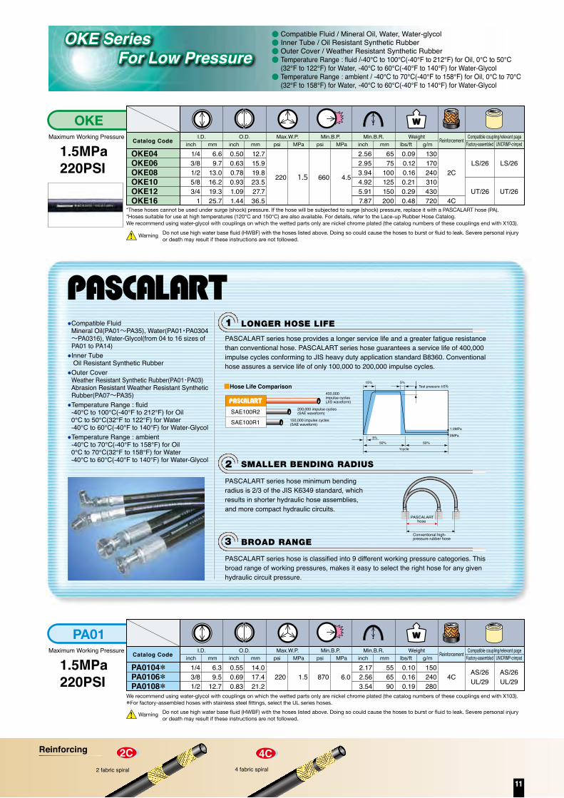
●Compatible Fluid Mineral Oil(PA01~PA35), Water(PA01・PA0304~PA0316), Water-Glycol(from 04 to 16 sizes of PA01 to PA14)
●Inner Tube Oil Resistant Synthetic Rubber
●Outer CoverWeather Resistant Synthetic Rubber(PA01・PA03)
Abrasion Resistant Weather Resistant Synthetic Rubber(PA07~PA35)
●Temperature Range : fluid-40℃ to 100℃(-40°F to 212°F) for Oil
0℃ to 50℃(32°F to 122°F) for Water -40℃ to 60℃(-40°F to 140°F) for Water-Glycol●Temperature Range : ambient
-40℃ to 70℃(-40°F to 158°F) for Oil 0℃ to 70℃(32°F to 158°F) for Water -40℃ to 60℃(-40°F to 140°F) for Water-Glycol
SMALLER BENDING RADIUS2
LONGER HOSE LIFE1
BROAD RANGE3
SAE100R2
SAE100R1
■Hose Life Comparison400,000impulse cycles(JIS waveform)
200,000 impulse cycles(SAE waveform)
150,000 impulse cycles(SAE waveform)
PASCALART series hose provides a longer service life and a greater fatigue resistance than conventional hose. PASCALART series hose guarantees a service life of 400,000 impulse cycles conforming to JIS heavy duty application standard B8360. Conventional hose assures a service life of only 100,000 to 200,000 impulse cycles.
PASCALART series hose is classified into 9 different working pressure categories. This broad range of working pressures, makes it easy to select the right hose for any given hydraulic circuit pressure.
1cycle50%
5%
15% 5%Test pressure ±5%
50%
1.0MPa
0MPa
PASCALART series hose minimum bending radius is 2/3 of the JIS K6349 standard, which results in shorter hydraulic hose assemblies, and more compact hydraulic circuits.
PASCALART
Conventional high-pressure rubber hose
hose
OKE SeriesFor Low Pressure
●●●●
●
6.69.7
13.016.219.325.7
0.500.630.780.931.091.44
12.715.919.823.527.736.5
220 1.5 660 4.5
2.562.953.944.925.917.87
6575
100125150200
130170240310430720
0.090.120.160.210.290.48
*These hoses cannot be used under surge (shock) pressure. If the hose will be subjected to surge (shock) pressure, replace it with a PASCALART hose (PA).*Hoses suitable for use at high temperatures (120°C and 150°C) are also available. For details, refer to the Lace-up Rubber Hose Catalog.We recommend using water-glycol with couplings on which the wetted parts only are nickel chrome plated (the catalog numbers of these couplings end with X103).
Warning Do not use high water base fluid (HWBF) with the hoses listed above. Doing so could cause the hoses to burst or fluid to leak. Severe personal injury or death may result if these instructions are not followed.
Warning Do not use high water base fluid (HWBF) with the hoses listed above. Doing so could cause the hoses to burst or fluid to leak. Severe personal injury or death may result if these instructions are not followed.
We recommend using water-glycol with couplings on which the wetted parts only are nickel chrome plated (the catalog numbers of these couplings end with X103).*For factory-assembled hoses with stainless steel fittings, select the UL series hoses.
Maximum Working Pressure
1.5MPa220PSI
PA01I.D.
PA0104*PA0106*PA0108*
Catalog Code
1/43/81/2
6.39.5
12.7
inch mmO.D.
0.550.690.83
14.017.421.2
inch mm
220 1.5
psi MPaMax.W.P.
870 6.0
psi MPaMin.B.P.
2.172.563.54
556590
inch mmMin.B.R.
0.100.160.19
150240280
lbs/ft g/mWeight Reinforcement
4C AS/26UL/29
AS/26UL/29
Maximum Working Pressure
1.5MPa220PSI
OKEI.D.
OKE04OKE06OKE08OKE10OKE12OKE16
Catalog Code
1/43/81/25/83/4
1
inch mmO.D.
inch mm psi MPaMax.W.P.
psi MPaMin.B.P.
inch mmMin.B.R.
lbs/ft g/mWeight Reinforcement
2C
4C
LS/26
UT/26
LS/26
UT/26
Factory-assembled UNICRIMP-crimpedCompatible coupling/relevant page
Factory-assembled UNICRIMP-crimpedCompatible coupling/relevant page
Compatible Fluid / Mineral Oil, Water, Water-glycolInner Tube / Oil Resistant Synthetic RubberOuter Cover / Weather Resistant Synthetic RubberTemperature Range : fluid /-40℃ to 100℃(-40°F to 212°F) for Oil, 0℃ to 50℃(32°F to 122°F) for Water, -40℃ to 60℃(-40°F to 140°F) for Water-Glycol Temperature Range : ambient / -40℃ to 70℃(-40°F to 158°F) for Oil, 0℃ to 70℃(32°F to 158°F) for Water, -40℃ to 60℃(-40°F to 140°F) for Water-Glycol
10
Hose Summary
●
●
●
●
●
●
●
●●●
●●
●●●
●●●●
●
●●●
●
●●●
●●●
●
●●●
●
●●●
●●●
●
●●●
●
98.068.568.568.5
68.5196.0147.0127.5117.598.088.073.568.5
245.0
245.0
294.02.0
2.02.02.0
20.5
14.5
14.510.5
20.5
16.014.0
68.514.0
14.0
31.027.524.5
10.5
10.510.5
25.522.020.517.016.0
9.57.5
19.515.014.512.010.510.5
5.0
14.014.0
14.010.5
20.520.5
20.5
17.014.0
9.0
Ordinaryhydraulic
piping
Crimpingmachine
not requiredSteampiping
−40 to +100 −40 to +80+40 to+93
−20 to+80
0 to+80
−40 to+70
+4 to+220
−30 to+80
−30 to+100
−40 to +50 (oil), 0 to +50 (water)
−40 to +70−40 to+70
−20 to+40
0 to+70
−40 to +50 (oil), 0 to +50 (water)−40 to +70 −40 to +70 −30 to +70
Mineral hydraulic oil
Ordinary hydraulic piping
Flexible type
Water Steam
Jacks
Mineralhydraulic oil
Mineralhydraulic oil
Water/mineralhydraulic oil
1 year 1 year 6 months 1 year 1 year
150,000 −150,000 150,00025,000150,000 200,000 25,000 10,0005,000 15,000 100,000 200,000100,000
Organicsolventpaint
Mineralhydraulic
oil
Mineralhydraulic
oil
Cleaning,shock
absorption
Machinetools,injury
protection
Paintsprays,
antistatictreatment
Ultra highpressurehydraulic
tools
Water jet devices,jacks, high-pressure
cleaning tools
48 49 52 54 57~61
Series
InsideDiameter
3.24.86.37.99.5
12.715.919.025.431.838.150.863.576.2
1/83/16
1/45/163/81/25/83/4
11-1/41-1/2
22-1/2
3
0203040506081012162024324048
mm Code Type KF KG SPL KA KB AG10 PS WSH SF SPL KF JAT JAM JAL JKY JAKinch
*For information about other couplings, contact us. For information about adapters, refer to pages 62 and 63.
HOSE
4× max. working pressure About 2× max. working pressure
JC70
KF KG SPL KA KB AG10 PS WSH SF SPL KF JAT JAM JAL JKY JAKJC70
Formachinetools
Forpaint
sprays
Forsteampiping
Forcleaning
Forjacks
Maxim
um w
orking pressure MPa
Relevant pageRFCG
CRS
SRH
HRK・K2K~K4
K~K3RF4F2
F2RQQ2
Q2R
29~32・50~51 54 58 59 6052~5350~51Hose type
COUPLING
Coupling thread type
Relevant page
Minimum burst pressure(MPa)
Fluid temperature(ºC)
Compatible fluid
Uses and features
Warranty period
Recommendedambient temperature
(ºC)
About3× max.workingpressure
4× max.workingpressure
4× max.workingpressure
3× max.workingpressure
2× max.workingpressure
PeriodNo. of
times used
Smallbendingradius
*Warranty is effective until the predetermined usage period expires or the impulse cycle count reaches the predetermined value, whichever occurs first. (The impulse cycle count refers to the number of times the hose has been pressurized under the specified hose usage conditions.)
Standard Resin Hoses Ultra-HighPressure Plastic HosesSpecial Application Plastic Hoses
●Compatible Fluid Mineral Oil(PA01~PA35), Water(PA01・PA0304~PA0316), Water-Glycol(from 04 to 16 sizes of PA01 to PA14)
●Inner Tube Oil Resistant Synthetic Rubber
●Outer CoverWeather Resistant Synthetic Rubber(PA01・PA03)
Abrasion Resistant Weather Resistant Synthetic Rubber(PA07~PA35)
●Temperature Range : fluid-40℃ to 100℃(-40°F to 212°F) for Oil
0℃ to 50℃(32°F to 122°F) for Water -40℃ to 60℃(-40°F to 140°F) for Water-Glycol●Temperature Range : ambient
-40℃ to 70℃(-40°F to 158°F) for Oil 0℃ to 70℃(32°F to 158°F) for Water -40℃ to 60℃(-40°F to 140°F) for Water-Glycol
SMALLER BENDING RADIUS2
LONGER HOSE LIFE1
BROAD RANGE3
SAE100R2
SAE100R1
■Hose Life Comparison400,000impulse cycles(JIS waveform)
200,000 impulse cycles(SAE waveform)
150,000 impulse cycles(SAE waveform)
PASCALART series hose provides a longer service life and a greater fatigue resistance than conventional hose. PASCALART series hose guarantees a service life of 400,000 impulse cycles conforming to JIS heavy duty application standard B8360. Conventional hose assures a service life of only 100,000 to 200,000 impulse cycles.
PASCALART series hose is classified into 9 different working pressure categories. This broad range of working pressures, makes it easy to select the right hose for any given hydraulic circuit pressure.
1cycle50%
5%
15% 5%Test pressure ±5%
50%
1.0MPa
0MPa
PASCALART series hose minimum bending radius is 2/3 of the JIS K6349 standard, which results in shorter hydraulic hose assemblies, and more compact hydraulic circuits.
PASCALART
Conventional high-pressure rubber hose
hose
OKE SeriesFor Low Pressure
●●●●
●
6.69.7
13.016.219.325.7
0.500.630.780.931.091.44
12.715.919.823.527.736.5
220 1.5 660 4.5
2.562.953.944.925.917.87
6575
100125150200
130170240310430720
0.090.120.160.210.290.48
*These hoses cannot be used under surge (shock) pressure. If the hose will be subjected to surge (shock) pressure, replace it with a PASCALART hose (PA).*Hoses suitable for use at high temperatures (120°C and 150°C) are also available. For details, refer to the Lace-up Rubber Hose Catalog.We recommend using water-glycol with couplings on which the wetted parts only are nickel chrome plated (the catalog numbers of these couplings end with X103).
Warning Do not use high water base fluid (HWBF) with the hoses listed above. Doing so could cause the hoses to burst or fluid to leak. Severe personal injury or death may result if these instructions are not followed.
Warning Do not use high water base fluid (HWBF) with the hoses listed above. Doing so could cause the hoses to burst or fluid to leak. Severe personal injury or death may result if these instructions are not followed.
We recommend using water-glycol with couplings on which the wetted parts only are nickel chrome plated (the catalog numbers of these couplings end with X103).*For factory-assembled hoses with stainless steel fittings, select the UL series hoses.
Maximum Working Pressure
1.5MPa220PSI
PA01I.D.
PA0104*PA0106*PA0108*
Catalog Code
1/43/81/2
6.39.5
12.7
inch mmO.D.
0.550.690.83
14.017.421.2
inch mm
220 1.5
psi MPaMax.W.P.
870 6.0
psi MPaMin.B.P.
2.172.563.54
556590
inch mmMin.B.R.
0.100.160.19
150240280
lbs/ft g/mWeight Reinforcement
4C AS/26UL/29
AS/26UL/29
Maximum Working Pressure
1.5MPa220PSI
OKEI.D.
OKE04OKE06OKE08OKE10OKE12OKE16
Catalog Code
1/43/81/25/83/4
1
inch mmO.D.
inch mm psi MPaMax.W.P.
psi MPaMin.B.P.
inch mmMin.B.R.
lbs/ft g/mWeight Reinforcement
2C
4C
LS/26
UT/26
LS/26
UT/26
Factory-assembled UNICRIMP-crimpedCompatible coupling/relevant page
Factory-assembled UNICRIMP-crimpedCompatible coupling/relevant page
Compatible Fluid / Mineral Oil, Water, Water-glycolInner Tube / Oil Resistant Synthetic RubberOuter Cover / Weather Resistant Synthetic RubberTemperature Range : fluid /-40℃ to 100℃(-40°F to 212°F) for Oil, 0℃ to 50℃(32°F to 122°F) for Water, -40℃ to 60℃(-40°F to 140°F) for Water-Glycol Temperature Range : ambient / -40℃ to 70℃(-40°F to 158°F) for Oil, 0℃ to 70℃(32°F to 158°F) for Water, -40℃ to 60℃(-40°F to 140°F) for Water-Glycol
Reinforcing
11

Maximum Working Pressure
3.5MPa500PSI
PA03I.D.
PA0304*PA0306*PA0308*PA0310PA0312PA0316PA0320PA0324
Catalog Code
1/43/81/25/83/4
11-1/41-1/2
6.39.5
12.715.919.025.431.838.1
inch mmO.D.
0.550.690.830.931.241.481.641.90
14.017.421.223.531.437.541.748.3
inch mm
500 3.5
psi MPaMax.W.P.
14.02,000
psi MPaMin.B.P.
2.172.563.544.335.316.697.879.84
556590
110135170200250
inch mmMin.B.R.
0.110.150.190.210.420.540.640.79
170220290310620800950
1,170
lbs/ft g/mWeight Reinforcement
4C
2C
4C
1W
AS/26
UL/29
UT/26
LC/26
AS/26
UL/29
UL/29
UT/26LC/26
Factory-assembled UNICRIMP-crimpedCompatible coupling/relevant page
Warning
We recommend using water-glycol with couplings on which the wetted parts only are nickel chrome plated (the catalog numbers of these couplings end with X103). *Factory-assembled hoses with stainless steel fittings are the UL series hoses.Do not use high water base fluid (HWBF) with the hoses listed above. Do not use water-glycol with either PA0320 or PA0324. Failure to observe these instructions could cause the hoses to burst or fluid to leak. Severe personal injury or death may result if these instructions are not followed.
Warning
We recommend using water-glycol with couplings on which the wetted parts only are nickel chrome plated (the catalog numbers of these couplings end with X103). *Factory-assembled hoses with stainless steel fittings are the UL and UX series hoses. Do not use high water base fluid (HWBF) with the hoses listed above. Do not use water-glycol with either PA0720 or PA0724 or PA0732. Failure to observe these instructions could cause the hoses to burst or fluid to leak. Severe personal injury or death may result if these instructions are not followed.
Warning
We recommend using water-glycol with couplings on which the wetted parts only are nickel chrome plated (the catalog numbers of these couplings end with X103). *Factory-assembled hoses with stainless steel fittings are the UL and UX series hoses.Do not use high water base fluid (HWBF) with the hoses listed above. Do not use water-glycol with PA1020, PA1024, or PA1032. Failure to observe these instructions could cause the hoses to burst or fluid to leak. Severe personal injury or death may result if these instructions are not followed.
Maximum Working Pressure
7.0MPa1,000PSI
PA07I.D.
PA0704*PA0706*PA0708*PA0710*PA0712*PA0716*PA0720PA0724PA0732
Catalog Code
1/43/81/25/83/4
11-1/41-1/2
2
6.39.5
12.715.919.025.431.838.150.8
inch mmO.D.
0.530.660.760.941.051.321.711.982.49
13.516.719.423.826.633.543.550.263.2
inch mm
1,000 7.0
psi MPaMax.W.P.
28.04,000
psi MPaMin.B.P.
2.172.953.154.335.126.898.66
10.6313.78
557580
110130175220270350
inch mmMin.B.R.
0.150.220.260.340.400.571.081.281.67
220330380510600850
1,6101,9102,490
lbs/ft g/mWeight Reinforcement
1W
2W
UZ/33UB/33UZ/33
UB/33
UZ/33
HW/40
UZ/33
UB/33
UZ/33
HW/40
Factory-assembled UNICRIMP-crimpedCompatible coupling/relevant page
Maximum Working Pressure
10.5MPa1,500PSI
PA10I.D.
PA1004*PA1006*PA1008*PA1010*PA1012*PA1016*PA1020 PA1024 PA1032
Catalog Code
1/43/81/25/83/4
11-1/41-1/2
2
6.39.5
12.715.919.025.431.838.150.8
inch mmO.D.
0.530.660.760.941.051.321.711.982.60
13.516.719.423.826.633.543.550.266.0
inch mm
1,500 10.5
psi MPaMax.W.P.
42.06,000
psi MPaMin.B.P.
2.172.953.154.335.126.898.66
10.6314.57
557580
110130175220270370
inch mmMin.B.R.
0.150.230.260.360.410.581.081.282.79
230340390530610860
1,6101,9104,150
lbs/ft g/mWeight Reinforcement
1W
2W
4S
UZ/33UB/33UZ/33
UB/33
UZ/33
HW/40
UZ/33
UB/33
UZ/33
HW/40
Factory-assembled UNICRIMP-crimpedCompatible coupling/relevant page
Maximum Working Pressure
14.0MPa2,000PSI
PA14I.D.
PA1404*PA1406*PA1408*PA1410*PA1412*PA1416*PA1420PA1424PA1432
Catalog Code
1/43/81/25/83/4
11-1/41-1/2
2
6.39.5
12.715.919.025.431.838.150.8
inch mmO.D.
0.530.660.761.001.151.411.712.072.60
13.516.719.425.429.335.843.552.766.0
inch mm
2,000 14.0
psi MPaMax.W.P.
56.08,000
psi MPaMin.B.P.
2.172.953.544.725.517.099.45
11.0214.57
557590
120140180240280370
inch mmMin.B.R.
0.160.230.270.500.630.831.082.062.79
240350400750940
1,2301,6103,0604,150
lbs/ft g/mWeight Reinforcement
1W
2W
4S
UZ/33UB/33UZ/33
UB/33
UZ/33HW・UZ/40HW/40
UZ/33
UB/33
UZ/33HW・UZ/40HW/40
Factory-assembled UNICRIMP-crimpedCompatible coupling/relevant page
Warning
We recommend using water-glycol with couplings on which the wetted parts only are nickel chrome plated (the catalog numbers of these couplings end with X103). *Factory-assembled hoses with stainless steel fittings are the UL and UX series hoses.Do not use high water base fluid (HWBF) with the hoses listed above. Do not use water-glycol with PA1420, PA1424, or PA1432, Failure to observe these instructions could cause the hoses to burst or fluid to leak. Severe personal injury or death may result if these instructions are not followed.
Maximum Working Pressure
17.0MPa2,500PSI
PA17I.D.
PA1704PA1706PA1708PA1710PA1712PA1716
Catalog Code
1/43/81/25/83/4
1
6.39.5
12.715.919.025.4
inch mmO.D.
0.530.660.761.001.151.41
13.516.719.425.429.335.8
inch mm
2,500 17.0
psi MPaMax.W.P.
68.010,000
psi MPaMin.B.P.
2.363.153.544.725.517.28
608090
120140185
inch mmMin.B.R.
0.160.240.280.520.630.87
240360420770950
1,300
lbs/ft g/mWeight Reinforcement
1W
2W
UZ/33UB/33UZ/33
UB/33
UZ/33
UB/33
Maximum Working Pressure
20.5MPa3,000PSI
PA21I.D.
PA2104PA2106PA2108PA2110PA2112PA2116PA2120PA2124PA2132
Catalog Code
1/43/81/25/83/4
11-1/41-1/2
2
6.39.5
12.715.919.025.431.838.150.8
inch mmO.D.
0.530.710.871.001.151.411.782.072.60
13.518.022.225.429.335.845.252.766.0
inch mm
3,000 20.5
psi MPaMax.W.P.
82.012,000
psi MPaMin.B.P.
2.763.544.335.516.698.27
10.2412.2016.93
7090
110140170210260310430
inch mmMin.B.R.
0.170.310.440.520.650.871.592.062.79
250470650770960
1,3002,3603,0604,150
lbs/ft g/mWeight Reinforcement
1W
2W
4S
UZ/33UB/33UZ/33
UB/33
UZ/33HW・UZ/40HW/40
UZ/33
UB/33
UZ/33HW・UZ/40HW/40
Factory-assembled UNICRIMP-crimpedCompatible coupling/relevant page
Maximum Working Pressure
27.5MPa4,000PSI
PA28I.D.
PA2804PA2806PA2808PA2810PA2812PA2816PA2820PA2824PA2832
Catalog Code
1/43/81/25/83/4
11-1/41-1/2
2
6.39.5
12.715.919.025.431.838.150.8
inch mmO.D.
0.590.750.871.041.141.411.802.202.95
15.119.122.226.429.035.945.655.975.0
inch mm
4,000 27.5
psi MPaMax.W.P.
110.016,000
psi MPaMin.B.P.
2.763.944.335.516.698.66
11.0212.6016.93
70100110140170220280320430
inch mmMin.B.R.
0.260.360.520.670.761.181.752.955.31
380540780
1,0001,1301,7502,6104,3907,900
lbs/ft g/mWeight Reinforcement
2W
4S
6S
UZ/33
UB/33
UZ/33UB/40KD/40
UZ/33
UB/33
UZ/33ーー
Factory-assembled UNICRIMP-crimpedCompatible coupling/relevant page
Maximum Working Pressure
34.5MPa5,000PSI
PA35I.D.
PA3504PA3506PA3508PA3510PA3512PA3516PA3520PA3524PA3532
Catalog Code
1/43/81/25/83/4
11-1/41-1/2
2
6.39.5
12.715.919.025.431.838.150.8
inch mmO.D.
0.590.750.871.041.141.441.932.202.95
15.119.122.226.429.036.649.055.975.0
inch mm
5,000 34.5
psi MPaMax.W.P.
138.020,000
psi MPaMin.B.P.
3.154.335.916.698.66
11.0212.9914.9619.69
80110150170220280330380500
inch mmMin.B.R.
0.260.370.540.670.761.342.592.985.38
390550800
1,0001,1302,0003,8504,4408,000
lbs/ft g/mWeight Reinforcement
2W
4S
6S
UZ/33
UB/33
UB/40EX/40
UZ/33
UB/33
UZ/33ーー
Factory-assembled UNICRIMP-crimpedCompatible coupling/relevant page
Factory-assembled UNICRIMP-crimpedCompatible coupling/relevant page
12
PA series
Reinforcing

Maximum Working Pressure
3.5MPa500PSI
PA03I.D.
PA0304*PA0306*PA0308*PA0310PA0312PA0316PA0320PA0324
Catalog Code
1/43/81/25/83/4
11-1/41-1/2
6.39.5
12.715.919.025.431.838.1
inch mmO.D.
0.550.690.830.931.241.481.641.90
14.017.421.223.531.437.541.748.3
inch mm
500 3.5
psi MPaMax.W.P.
14.02,000
psi MPaMin.B.P.
2.172.563.544.335.316.697.879.84
556590
110135170200250
inch mmMin.B.R.
0.110.150.190.210.420.540.640.79
170220290310620800950
1,170
lbs/ft g/mWeight Reinforcement
4C
2C
4C
1W
AS/26
UL/29
UT/26
LC/26
AS/26
UL/29
UL/29
UT/26LC/26
Factory-assembled UNICRIMP-crimpedCompatible coupling/relevant page
Warning
We recommend using water-glycol with couplings on which the wetted parts only are nickel chrome plated (the catalog numbers of these couplings end with X103). *Factory-assembled hoses with stainless steel fittings are the UL series hoses.Do not use high water base fluid (HWBF) with the hoses listed above. Do not use water-glycol with either PA0320 or PA0324. Failure to observe these instructions could cause the hoses to burst or fluid to leak. Severe personal injury or death may result if these instructions are not followed.
Warning
We recommend using water-glycol with couplings on which the wetted parts only are nickel chrome plated (the catalog numbers of these couplings end with X103). *Factory-assembled hoses with stainless steel fittings are the UL and UX series hoses. Do not use high water base fluid (HWBF) with the hoses listed above. Do not use water-glycol with either PA0720 or PA0724 or PA0732. Failure to observe these instructions could cause the hoses to burst or fluid to leak. Severe personal injury or death may result if these instructions are not followed.
Warning
We recommend using water-glycol with couplings on which the wetted parts only are nickel chrome plated (the catalog numbers of these couplings end with X103). *Factory-assembled hoses with stainless steel fittings are the UL and UX series hoses.Do not use high water base fluid (HWBF) with the hoses listed above. Do not use water-glycol with PA1020, PA1024, or PA1032. Failure to observe these instructions could cause the hoses to burst or fluid to leak. Severe personal injury or death may result if these instructions are not followed.
Maximum Working Pressure
7.0MPa1,000PSI
PA07I.D.
PA0704*PA0706*PA0708*PA0710*PA0712*PA0716*PA0720PA0724PA0732
Catalog Code
1/43/81/25/83/4
11-1/41-1/2
2
6.39.5
12.715.919.025.431.838.150.8
inch mmO.D.
0.530.660.760.941.051.321.711.982.49
13.516.719.423.826.633.543.550.263.2
inch mm
1,000 7.0
psi MPaMax.W.P.
28.04,000
psi MPaMin.B.P.
2.172.953.154.335.126.898.66
10.6313.78
557580
110130175220270350
inch mmMin.B.R.
0.150.220.260.340.400.571.081.281.67
220330380510600850
1,6101,9102,490
lbs/ft g/mWeight Reinforcement
1W
2W
UZ/33UB/33UZ/33
UB/33
UZ/33
HW/40
UZ/33
UB/33
UZ/33
HW/40
Factory-assembled UNICRIMP-crimpedCompatible coupling/relevant page
Maximum Working Pressure
10.5MPa1,500PSI
PA10I.D.
PA1004*PA1006*PA1008*PA1010*PA1012*PA1016*PA1020 PA1024 PA1032
Catalog Code
1/43/81/25/83/4
11-1/41-1/2
2
6.39.5
12.715.919.025.431.838.150.8
inch mmO.D.
0.530.660.760.941.051.321.711.982.60
13.516.719.423.826.633.543.550.266.0
inch mm
1,500 10.5
psi MPaMax.W.P.
42.06,000
psi MPaMin.B.P.
2.172.953.154.335.126.898.66
10.6314.57
557580
110130175220270370
inch mmMin.B.R.
0.150.230.260.360.410.581.081.282.79
230340390530610860
1,6101,9104,150
lbs/ft g/mWeight Reinforcement
1W
2W
4S
UZ/33UB/33UZ/33
UB/33
UZ/33
HW/40
UZ/33
UB/33
UZ/33
HW/40
Factory-assembled UNICRIMP-crimpedCompatible coupling/relevant page
Maximum Working Pressure
14.0MPa2,000PSI
PA14I.D.
PA1404*PA1406*PA1408*PA1410*PA1412*PA1416*PA1420PA1424PA1432
Catalog Code
1/43/81/25/83/4
11-1/41-1/2
2
6.39.5
12.715.919.025.431.838.150.8
inch mmO.D.
0.530.660.761.001.151.411.712.072.60
13.516.719.425.429.335.843.552.766.0
inch mm
2,000 14.0
psi MPaMax.W.P.
56.08,000
psi MPaMin.B.P.
2.172.953.544.725.517.099.45
11.0214.57
557590
120140180240280370
inch mmMin.B.R.
0.160.230.270.500.630.831.082.062.79
240350400750940
1,2301,6103,0604,150
lbs/ft g/mWeight Reinforcement
1W
2W
4S
UZ/33UB/33UZ/33
UB/33
UZ/33HW・UZ/40HW/40
UZ/33
UB/33
UZ/33HW・UZ/40HW/40
Factory-assembled UNICRIMP-crimpedCompatible coupling/relevant page
Warning
We recommend using water-glycol with couplings on which the wetted parts only are nickel chrome plated (the catalog numbers of these couplings end with X103). *Factory-assembled hoses with stainless steel fittings are the UL and UX series hoses.Do not use high water base fluid (HWBF) with the hoses listed above. Do not use water-glycol with PA1420, PA1424, or PA1432, Failure to observe these instructions could cause the hoses to burst or fluid to leak. Severe personal injury or death may result if these instructions are not followed.
Maximum Working Pressure
17.0MPa2,500PSI
PA17I.D.
PA1704PA1706PA1708PA1710PA1712PA1716
Catalog Code
1/43/81/25/83/4
1
6.39.5
12.715.919.025.4
inch mmO.D.
0.530.660.761.001.151.41
13.516.719.425.429.335.8
inch mm
2,500 17.0
psi MPaMax.W.P.
68.010,000
psi MPaMin.B.P.
2.363.153.544.725.517.28
608090
120140185
inch mmMin.B.R.
0.160.240.280.520.630.87
240360420770950
1,300
lbs/ft g/mWeight Reinforcement
1W
2W
UZ/33UB/33UZ/33
UB/33
UZ/33
UB/33
Maximum Working Pressure
20.5MPa3,000PSI
PA21I.D.
PA2104PA2106PA2108PA2110PA2112PA2116PA2120PA2124PA2132
Catalog Code
1/43/81/25/83/4
11-1/41-1/2
2
6.39.5
12.715.919.025.431.838.150.8
inch mmO.D.
0.530.710.871.001.151.411.782.072.60
13.518.022.225.429.335.845.252.766.0
inch mm
3,000 20.5
psi MPaMax.W.P.
82.012,000
psi MPaMin.B.P.
2.763.544.335.516.698.27
10.2412.2016.93
7090
110140170210260310430
inch mmMin.B.R.
0.170.310.440.520.650.871.592.062.79
250470650770960
1,3002,3603,0604,150
lbs/ft g/mWeight Reinforcement
1W
2W
4S
UZ/33UB/33UZ/33
UB/33
UZ/33HW・UZ/40HW/40
UZ/33
UB/33
UZ/33HW・UZ/40HW/40
Factory-assembled UNICRIMP-crimpedCompatible coupling/relevant page
Maximum Working Pressure
27.5MPa4,000PSI
PA28I.D.
PA2804PA2806PA2808PA2810PA2812PA2816PA2820PA2824PA2832
Catalog Code
1/43/81/25/83/4
11-1/41-1/2
2
6.39.5
12.715.919.025.431.838.150.8
inch mmO.D.
0.590.750.871.041.141.411.802.202.95
15.119.122.226.429.035.945.655.975.0
inch mm
4,000 27.5
psi MPaMax.W.P.
110.016,000
psi MPaMin.B.P.
2.763.944.335.516.698.66
11.0212.6016.93
70100110140170220280320430
inch mmMin.B.R.
0.260.360.520.670.761.181.752.955.31
380540780
1,0001,1301,7502,6104,3907,900
lbs/ft g/mWeight Reinforcement
2W
4S
6S
UZ/33
UB/33
UZ/33UB/40KD/40
UZ/33
UB/33
UZ/33ーー
Factory-assembled UNICRIMP-crimpedCompatible coupling/relevant page
Maximum Working Pressure
34.5MPa5,000PSI
PA35I.D.
PA3504PA3506PA3508PA3510PA3512PA3516PA3520PA3524PA3532
Catalog Code
1/43/81/25/83/4
11-1/41-1/2
2
6.39.5
12.715.919.025.431.838.150.8
inch mmO.D.
0.590.750.871.041.141.441.932.202.95
15.119.122.226.429.036.649.055.975.0
inch mm
5,000 34.5
psi MPaMax.W.P.
138.020,000
psi MPaMin.B.P.
3.154.335.916.698.66
11.0212.9914.9619.69
80110150170220280330380500
inch mmMin.B.R.
0.260.370.540.670.761.342.592.985.38
390550800
1,0001,1302,0003,8504,4408,000
lbs/ft g/mWeight Reinforcement
2W
4S
6S
UZ/33
UB/33
UB/40EX/40
UZ/33
UB/33
UZ/33ーー
Factory-assembled UNICRIMP-crimpedCompatible coupling/relevant page
Factory-assembled UNICRIMP-crimpedCompatible coupling/relevant page
13

Compatible Fluid / Mineral OilInner Tube / Oil Resistant Synthetic RubberOuter Cover / Abrasion Resistant Weather Resistant Synthetic RubberTemperature Range : fluid / -40℃ to 100℃ (-40°F to 212°F) Temperature Range : ambient / -40℃ to 70℃ (-40°F to 158°F)
Based on
Smaller bending radiusMore flexible
Maximum Working Pressure
7.0MPa1,000PSI
PF07I.D.
PF0704*PF0706*PF0708*
Catalog Code
1/43/81/2
6.39.5
12.7
inch mmO.D.
0.470.610.73
11.915.518.5
inch mm
1,000 7.0
psi MPaMax.W.P.
28.04,000
psi MPaMin.B.P.
1.571.972.36
405060
inch mmMin.B.R.
0.090.150.22
140220320
lbs/ft g/mWeight Reinforcement
1WUZ/33UB/33UZ/33
UL・UZ/33
UB/33
Factory-assembled UNICRIMP-crimpedCompatible coupling/relevant page
*For factory-assembled hoses with stainless steel fittings, select the UL series hoses.
Maximum Working Pressure
14.0MPa2,000PSI
PF14I.D.
PF1404*PF1406*PF1408*
Catalog Code
1/43/81/2
6.39.5
12.7
inch mmO.D.
0.470.610.75
11.915.519.0
inch mm
2,000 14.0
psi MPaMax.W.P.
56.08,000
psi MPaMin.B.P.
1.571.972.36
405060
inch mmMin.B.R.
0.100.150.24
150230350
lbs/ft g/mWeight Reinforcement
1WUZ/33UB/33UZ/33
UL・UZ/33
UB/33
Factory-assembled UNICRIMP-crimpedCompatible coupling/relevant page
*For factory-assembled hoses with stainless steel fittings, select the UL series hoses.
Maximum Working Pressure
17.0MPa2,500PSI
PF17I.D.
PF1704*PF1706*PF1708*
Catalog Code
1/43/81/2
6.39.5
12.7
inch mmO.D.
0.500.660.80
12.616.720.2
inch mm
2,500 17.0
psi MPaMax.W.P.
68.010,000
psi MPaMin.B.P.
1.772.363.15
456080
inch mmMin.B.R.
0.130.220.34
190330500
lbs/ft g/mWeight Reinforcement
1W
2W
UZ/33UB/33UZ/33
UL・UZ/33
UB/33
Factory-assembled UNICRIMP-crimpedCompatible coupling/relevant page
*For factory-assembled hoses with stainless steel fittings, select the UL series hoses.
Maximum Working Pressure
24.5MPa3,500PSI
PFWI.D.
PFW04PFW06PFW08
Catalog Code
1/43/81/2
6.39.5
12.7
inch mmO.D.
0.530.680.80
13.417.220.2
inch mm
3,500 24.5
psi MPaMax.W.P.
98.014,000
psi MPaMin.B.P.
1.972.763.54
507090
inch mmMin.B.R.
0.190.290.36
290430540
lbs/ft g/mWeight Reinforcement
2WUZ/33UB/33UZ/33
ー
Factory-assembled UNICRIMP-crimpedCompatible coupling/relevant page
Maximum Working Pressure
27.5MPa4,000PSI
PFHI.D.
PFH04PFH06PFH08
Catalog Code
1/43/81/2
6.39.5
12.7
inch mmO.D.
0.530.680.80
13.417.220.2
inch mm
4,000 27.5
psi MPaMax.W.P.
110.016,000
psi MPaMin.B.P.
1.972.763.54
507090
inch mmMin.B.R.
0.200.300.37
300450550
lbs/ft g/mWeight Reinforcement
2WUZ/33UB/33UZ/33
UZ/33
UB/33
Factory-assembled UNICRIMP-crimpedCompatible coupling/relevant page
*For factory-assembled hoses with stainless steel fittings, select the UL series hoses.
Maximum Working Pressure
20.5MPa3,000PSI
PF21I.D.
PF2104*PF2106PF2108PF2110PF2112PF2116
Catalog Code
1/43/81/25/83/4
1
6.39.5
12.715.919.025.4
inch mmO.D.
0.500.680.800.981.131.41
12.617.220.224.928.735.8
inch mm
3,000 20.5
psi MPaMax.W.P.
82.012,000
psi MPaMin.B.P.
1.972.563.353.944.727.48
506585
100120190
inch mmMin.B.R.
0.130.280.360.480.610.84
200420530710910
1,250
lbs/ft g/mWeight Reinforcement
1W
2W
UZ/33UB/33UZ/33
UB/33
UZ/33
UB/33
Factory-assembled UNICRIMP-crimpedCompatible coupling/relevant page
●●●
●●
HQ35 SeriesImpulse cycle 1,200,000
●●●●●
Compatible Fluid / Mineral OilInner Tube / Oil Resistant Synthetic RubberOuter Cover / Abrasion Resistant Weather Resistant Synthetic RubberTemperature Range : fluid / -40℃ to 100℃(-40℉ to 212℉)Temperature Range : ambient / -40℃ to 70℃(-40 ℉ to 158℉)
Maximum Working Pressure
34.5MPa5,000PSI
HQ35I.D.
HQ3508HQ3510HQ3512HQ3516HQ3520
Catalog Code
1/25/83/4
11-1/4
inch mmO.D.
0.871.041.141.441.92
inch mm
5,000
psi MPaMax.W.P.
psi MPaMin.B.P.
4.726.307.879.45
12.99
inch mmMin.B.R.
0.500.660.731.312.51
12.715.919.025.431.8
22.226.429.036.648.7
34.5 138.020,000
120160200240330
750990
1,0801,9503,730
lbs/ft g/mWeight Reinforcement
4S
6S
UB/33UB/33
UZ/33
Factory-assembled UNICRIMP-crimpedCompatible coupling/relevant page
Maximum Working Pressure
27.5MPa4,000PSI
SQ28I.D.
SQ2808SQ2810SQ2812
Catalog Code
1/25/83/4
inch mmO.D.
0.891.051.15
inch mm
4,000
psi MPaMax.W.P.
psi MPaMin.B.P.
4.725.917.09
inch mmMin.B.R.
0.520.680.74
12.715.919.0
22.526.729.3
27.5 110.016,000120150180
77010101100
lbs/ft g/mWeight Reinforcement
4S UB/33 ー
Factory-assembled UNICRIMP-crimpedCompatible coupling/relevant page
Maximum Working Pressure
36.0~38.0MPa5,200~5,500PSI
CQ36/38I.D.
CQ3604CQ3606CQ3608CQ3610CQ3812CQ3816CQ3820
Catalog Code
1/43/81/25/83/4
11-1/4
inch mmO.D.
0.590.760.871.041.191.441.87
inch mm
5,200
psi MPaMax.W.P.
psi MPaMin.B.P.
3.154.335.515.918.27
10.2412.99
inch mmMin.B.R.
0.260.380.500.670.941.312.42
6.39.5
12.715.919.025.431.8
15.119.222.226.430.136.647.4
80110140150210260330
380570750
1000140019503600
lbs/ft g/mWeight Reinforcement
2W
4S
6S
UZ/33
UB/33
UB(CX)/33
UB/33
UZ/33
UB/33
ー
Factory-assembled UNICRIMP-crimpedCompatible coupling/relevant page
CQ Series Impulse cycle 1,000,000 MSHA Approved
●●●●
●
Compatible Fluid / Mineral OilInner Tube / Oil Resistant Synthetic RubberOuter Cover / Abrasion Resistant Weather Resistant Synthetic RubberTemperature Range : fluid /-40℃ to +100℃(-40℉ to +212℉)(CQ36) fluid -40℃ to +120℃(-40℉ to +248℉)(CQ38)Temperature Range : ambient / -40℃ to 70℃(-40 ℉ to 158℉)
5,500
36.0
38.0
144.0
152.0
20,800
22,000
SQ28 SeriesUltra High Abrasion resistant hose
●●●
●●
Compatible Fluid / Mineral OilInner Tube / Oil Resistant Synthetic RubberOuter Cover / Weather Resistant Synthetic Rubber with Ultra High Molecular Weight PolyethyleneTemperature Range : fluid / -40℃ to +100℃(-40℉ to +212℉)Temperature Range : ambient / -40℃ to +70℃(-40℉ to +158℉)
SQ Hose
PA series
Abrasion Loss : 0.000g
Abrasion Loss : 0.019g
*Abrasion Resitance test Test method; ISO6945 (Old Edition) Abrasion test
Tset condition; Abrasion 2,000 timesSQ Hose is covered with Ultra High Molecular Weight Polyethylene at outer layer. It is useful for rasping install.
Ultra High Abrasion Resistance Outer Cover
14
PF series
Reinforcing

Compatible Fluid / Mineral OilInner Tube / Oil Resistant Synthetic RubberOuter Cover / Abrasion Resistant Weather Resistant Synthetic RubberTemperature Range : fluid / -40℃ to 100℃ (-40°F to 212°F) Temperature Range : ambient / -40℃ to 70℃ (-40°F to 158°F)
Based on
Smaller bending radiusMore flexible
Maximum Working Pressure
7.0MPa1,000PSI
PF07I.D.
PF0704*PF0706*PF0708*
Catalog Code
1/43/81/2
6.39.5
12.7
inch mmO.D.
0.470.610.73
11.915.518.5
inch mm
1,000 7.0
psi MPaMax.W.P.
28.04,000
psi MPaMin.B.P.
1.571.972.36
405060
inch mmMin.B.R.
0.090.150.22
140220320
lbs/ft g/mWeight Reinforcement
1WUZ/33UB/33UZ/33
UL・UZ/33
UB/33
Factory-assembled UNICRIMP-crimpedCompatible coupling/relevant page
*For factory-assembled hoses with stainless steel fittings, select the UL series hoses.
Maximum Working Pressure
14.0MPa2,000PSI
PF14I.D.
PF1404*PF1406*PF1408*
Catalog Code
1/43/81/2
6.39.5
12.7
inch mmO.D.
0.470.610.75
11.915.519.0
inch mm
2,000 14.0
psi MPaMax.W.P.
56.08,000
psi MPaMin.B.P.
1.571.972.36
405060
inch mmMin.B.R.
0.100.150.24
150230350
lbs/ft g/mWeight Reinforcement
1WUZ/33UB/33UZ/33
UL・UZ/33
UB/33
Factory-assembled UNICRIMP-crimpedCompatible coupling/relevant page
*For factory-assembled hoses with stainless steel fittings, select the UL series hoses.
Maximum Working Pressure
17.0MPa2,500PSI
PF17I.D.
PF1704*PF1706*PF1708*
Catalog Code
1/43/81/2
6.39.5
12.7
inch mmO.D.
0.500.660.80
12.616.720.2
inch mm
2,500 17.0
psi MPaMax.W.P.
68.010,000
psi MPaMin.B.P.
1.772.363.15
456080
inch mmMin.B.R.
0.130.220.34
190330500
lbs/ft g/mWeight Reinforcement
1W
2W
UZ/33UB/33UZ/33
UL・UZ/33
UB/33
Factory-assembled UNICRIMP-crimpedCompatible coupling/relevant page
*For factory-assembled hoses with stainless steel fittings, select the UL series hoses.
Maximum Working Pressure
24.5MPa3,500PSI
PFWI.D.
PFW04PFW06PFW08
Catalog Code
1/43/81/2
6.39.5
12.7
inch mmO.D.
0.530.680.80
13.417.220.2
inch mm
3,500 24.5
psi MPaMax.W.P.
98.014,000
psi MPaMin.B.P.
1.972.763.54
507090
inch mmMin.B.R.
0.190.290.36
290430540
lbs/ft g/mWeight Reinforcement
2WUZ/33UB/33UZ/33
ー
Factory-assembled UNICRIMP-crimpedCompatible coupling/relevant page
Maximum Working Pressure
27.5MPa4,000PSI
PFHI.D.
PFH04PFH06PFH08
Catalog Code
1/43/81/2
6.39.5
12.7
inch mmO.D.
0.530.680.80
13.417.220.2
inch mm
4,000 27.5
psi MPaMax.W.P.
110.016,000
psi MPaMin.B.P.
1.972.763.54
507090
inch mmMin.B.R.
0.200.300.37
300450550
lbs/ft g/mWeight Reinforcement
2WUZ/33UB/33UZ/33
UZ/33
UB/33
Factory-assembled UNICRIMP-crimpedCompatible coupling/relevant page
*For factory-assembled hoses with stainless steel fittings, select the UL series hoses.
Maximum Working Pressure
20.5MPa3,000PSI
PF21I.D.
PF2104*PF2106PF2108PF2110PF2112PF2116
Catalog Code
1/43/81/25/83/4
1
6.39.5
12.715.919.025.4
inch mmO.D.
0.500.680.800.981.131.41
12.617.220.224.928.735.8
inch mm
3,000 20.5
psi MPaMax.W.P.
82.012,000
psi MPaMin.B.P.
1.972.563.353.944.727.48
506585
100120190
inch mmMin.B.R.
0.130.280.360.480.610.84
200420530710910
1,250
lbs/ft g/mWeight Reinforcement
1W
2W
UZ/33UB/33UZ/33
UB/33
UZ/33
UB/33
Factory-assembled UNICRIMP-crimpedCompatible coupling/relevant page
●●●
●●
HQ35 SeriesImpulse cycle 1,200,000
●●●●●
Compatible Fluid / Mineral OilInner Tube / Oil Resistant Synthetic RubberOuter Cover / Abrasion Resistant Weather Resistant Synthetic RubberTemperature Range : fluid / -40℃ to 100℃(-40℉ to 212℉)Temperature Range : ambient / -40℃ to 70℃(-40 ℉ to 158℉)
Maximum Working Pressure
34.5MPa5,000PSI
HQ35I.D.
HQ3508HQ3510HQ3512HQ3516HQ3520
Catalog Code
1/25/83/4
11-1/4
inch mmO.D.
0.871.041.141.441.92
inch mm
5,000
psi MPaMax.W.P.
psi MPaMin.B.P.
4.726.307.879.45
12.99
inch mmMin.B.R.
0.500.660.731.312.51
12.715.919.025.431.8
22.226.429.036.648.7
34.5 138.020,000
120160200240330
750990
1,0801,9503,730
lbs/ft g/mWeight Reinforcement
4S
6S
UB/33UB/33
UZ/33
Factory-assembled UNICRIMP-crimpedCompatible coupling/relevant page
Maximum Working Pressure
27.5MPa4,000PSI
SQ28I.D.
SQ2808SQ2810SQ2812
Catalog Code
1/25/83/4
inch mmO.D.
0.891.051.15
inch mm
4,000
psi MPaMax.W.P.
psi MPaMin.B.P.
4.725.917.09
inch mmMin.B.R.
0.520.680.74
12.715.919.0
22.526.729.3
27.5 110.016,000120150180
77010101100
lbs/ft g/mWeight Reinforcement
4S UB/33 ー
Factory-assembled UNICRIMP-crimpedCompatible coupling/relevant page
Maximum Working Pressure
36.0~38.0MPa5,200~5,500PSI
CQ36/38I.D.
CQ3604CQ3606CQ3608CQ3610CQ3812CQ3816CQ3820
Catalog Code
1/43/81/25/83/4
11-1/4
inch mmO.D.
0.590.760.871.041.191.441.87
inch mm
5,200
psi MPaMax.W.P.
psi MPaMin.B.P.
3.154.335.515.918.27
10.2412.99
inch mmMin.B.R.
0.260.380.500.670.941.312.42
6.39.5
12.715.919.025.431.8
15.119.222.226.430.136.647.4
80110140150210260330
380570750
1000140019503600
lbs/ft g/mWeight Reinforcement
2W
4S
6S
UZ/33
UB/33
UB(CX)/33
UB/33
UZ/33
UB/33
ー
Factory-assembled UNICRIMP-crimpedCompatible coupling/relevant page
CQ Series Impulse cycle 1,000,000 MSHA Approved
●●●●
●
Compatible Fluid / Mineral OilInner Tube / Oil Resistant Synthetic RubberOuter Cover / Abrasion Resistant Weather Resistant Synthetic RubberTemperature Range : fluid /-40℃ to +100℃(-40℉ to +212℉)(CQ36) fluid -40℃ to +120℃(-40℉ to +248℉)(CQ38)Temperature Range : ambient / -40℃ to 70℃(-40 ℉ to 158℉)
5,500
36.0
38.0
144.0
152.0
20,800
22,000
SQ28 SeriesUltra High Abrasion resistant hose
●●●
●●
Compatible Fluid / Mineral OilInner Tube / Oil Resistant Synthetic RubberOuter Cover / Weather Resistant Synthetic Rubber with Ultra High Molecular Weight PolyethyleneTemperature Range : fluid / -40℃ to +100℃(-40℉ to +212℉)Temperature Range : ambient / -40℃ to +70℃(-40℉ to +158℉)
SQ Hose
PA series
Abrasion Loss : 0.000g
Abrasion Loss : 0.019g
*Abrasion Resitance test Test method; ISO6945 (Old Edition) Abrasion test
Tset condition; Abrasion 2,000 timesSQ Hose is covered with Ultra High Molecular Weight Polyethylene at outer layer. It is useful for rasping install.
Ultra High Abrasion Resistance Outer Cover
15
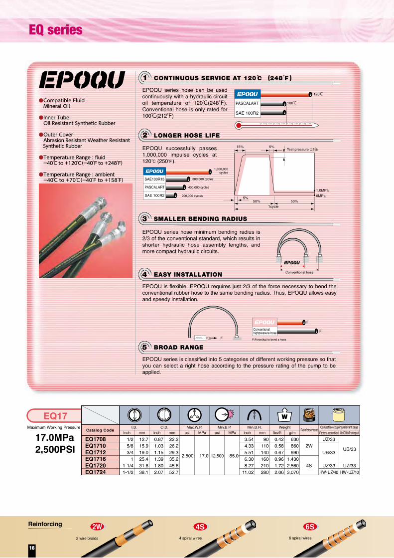
LONGER HOSE LIFE2
CONTINUOUS SERVICE AT 120 (248 )1
SMALLER BENDING RADIUS3
EASY INSTALLATION4
BROAD RANGE5
EPOQU series hose can be used continuously with a hydraulic circuit oil temperature of 120℃(248°F). Conventional hose is only rated for 100℃(212°F)
EPOQU successfully passes 1,000,000 impulse cycles at 120 (250 ).
EPOQU series hose minimum bending radius is 2/3 of the conventional standard, which results in shorter hydraulic hose assembly lengths, and more compact hydraulic circuits.
EPOQU is flexible. EPOQU requires just 2/3 of the force necessary to bend the conventional rubber hose to the same bending radius. Thus, EPOQU allows easy and speedy installation.
EPOQU series is classified into 5 categories of different working pressure so that you can select a right hose according to the pressure rating of the pump to be applied.
PASCALART
SAE 100R2
120℃
100℃
1cycle50%
5%
15% 5%Test pressure ±5%
50%
1.0MPa0MPa
SAE100R15
SAE 100R2
PASCALART
1,000,000 cycles
400,000 cycles
500,000 cycles
200,000 cycles
Conventional hose
F
FConventionalhighpressure hose
F:Force(kg) to bend a hoseF
●Compatible Fluid Mineral Oil
●Inner Tube Oil Resistant Synthetic Rubber
●Outer Cover Abrasion Resistant Weather Resistant Synthetic Rubber
●Temperature Range : fluid -40℃ to +120℃(-40℉ to +248℉)
●Temperature Range : ambient -40℃ to +70℃(-40℉ to +158℉)
12.715.919.025.431.838.1
22.226.229.335.245.652.7
90110140160210280
630860990
1,4302,5603,070
Maximum Working Pressure
17.0MPa2,500PSI
EQ17I.D.
EQ1708EQ1710 EQ1712EQ1716EQ1720 EQ1724
Catalog Code
1/25/83/4
11-1/41-1/2
inch mmO.D.
0.871.031.151.391.802.07
inch mm
2,500
psi MPaMax.W.P.
psi MPaMin.B.P.
3.544.335.516.308.27
11.02
inch mmMin.B.R.
0.420.580.670.961.722.06
17.0 85.012,500
lbs/ft g/mWeight Reinforcement
2W
4S
UZ/33
UB/33
UZ/33HW・UZ/40
UB/33
UZ/33HW・UZ/40
Factory-assembled UNICRIMP-crimpedCompatible coupling/relevant page
Maximum Working Pressure
20.5MPa3,000PSI
EQ21I.D.
EQ2108EQ2110 EQ2112EQ2116EQ2120EQ2124EQ2132
Catalog Code inch mmO.D.
inch mm psi MPaMax.W.P.
psi MPaMin.B.P.
inch mmMin.B.R.
lbs/ft g/mWeight Reinforcement
2W
4S
6S
UZ/33
UB/34
UZ/33HW・UZ/40
KN/40
UB/33
UZ/33HW・UZ/40-
Factory-assembled UNICRIMP-crimpedCompatible coupling/relevant page
Maximum Working Pressure
24.5MPa3,500PSI
EQ25I.D.
EQ2508EQ2510EQ2512EQ2516EQ2520EQ2524
Catalog Code
1/25/83/4
11-1/41-1/2
inch mmO.D.
0.871.041.141.411.802.20
inch mm
3,500
psi MPaMax.W.P.
psi MPaMin.B.P.
3.945.126.307.09
10.2412.60
inch mmMin.B.R.
0.520.670.761.181.722.92
24.5 122.517,500
lbs/ft g/mWeight Reinforcement
4S
6S
UB/33
UZ/33UB/40
UB/33
UZ/33-
UB/33
UZ/33-
Factory-assembled UNICRIMP-crimpedCompatible coupling/relevant page
Maximum Working Pressure
27.5MPa4,000PSI
EQ28I.D.
EQ2808EQ2810EQ2812EQ2816EQ2820EQ2824
Catalog Code
1/25/83/4
11-1/41-1/2
inch mmO.D.
0.871.041.141.411.912.20
inch mm
4,000
psi MPaMax.W.P.
psi MPaMin.B.P.
3.945.126.307.87
11.8114.17
inch mmMin.B.R.
0.520.670.761.182.452.92
27.5 137.520,000
lbs/ft g/mWeight Reinforcement
4S
6S
UB/33
UZ/33UB/40
Factory-assembled UNICRIMP-crimpedCompatible coupling/relevant page
Maximum Working Pressure
31.0MPa4,500PSI
EQ31I.D.
EQ3108EQ3110EQ3112EQ3116EQ3120EQ3124EQ3132
Catalog Code
1/25/83/4
11-1/41-1/2
2
inch mmO.D.
0.871.041.141.441.932.202.95
inch mm
4,500
psi MPaMax.W.P.
psi MPaMin.B.P.
4.726.307.879.45
12.6015.3522.05
inch mmMin.B.R.
0.540.670.761.342.553.025.31
31.0 155.022,500
lbs/ft g/mWeight Reinforcement
4S
6S
UB/33
UB/40EX/40
UB/33
UZ/33
-
Factory-assembled UNICRIMP-crimpedCompatible coupling/relevant page
12.715.919.025.431.838.150.8
22.226.229.035.245.652.770.0
100130140180230310430
630860
1,1301,4302,5603,0705,800
12.715.919.025.431.838.1
22.226.429.035.945.655.9
100130160180260320
7801,0001,1301,7502,5604,340
12.7 15.9 19.0 25.4 31.8 38.1
22.226.429.035.948.655.9
100130160200300360
7801,0001,1301,7503,6404,340
12.715.919.025.431.838.150.8
22.226.429.036.649.055.975.0
120160200240320390560
8001,0001,1302,0003,8004,5007,900
Maximum Working Pressure
35.0MPa5,000PSI
EQ35I.D.
EQ3508EQ3512EQ3516EQ3520EQ3524
Catalog Code
12.719.025.431.838.1
1/23/4
11-1/41-1/2
inch mmO.D.
0.871.191.441.872.19
inch mm
5,000
psi MPaMax.W.P.
psi MPaMin.B.P.
5.127.489.45
12.9914.96
inch mmMin.B.R.
0.510.941.312.412.96
35.0 160.023,200
lbs/ft g/mWeight Reinforcement
4S
6S
UB/33
UB/40
UB/33
-
Factory-assembled UNICRIMP-crimpedCompatible coupling/relevant page
22.230.136.647.455.6
130 190 240 330 380
7601,4001,9503,5904,410
1/25/83/4
11-1/41-1/2
2
0.871.031.141.391.802.072.76
3,000
3.945.125.517.099.06
12.2016.93
0.420.580.760.961.722.063.90
20.5 102.515,000
EQ series
16
Reinforcing

LONGER HOSE LIFE2
CONTINUOUS SERVICE AT 120 (248 )1
SMALLER BENDING RADIUS3
EASY INSTALLATION4
BROAD RANGE5
EPOQU series hose can be used continuously with a hydraulic circuit oil temperature of 120℃(248°F). Conventional hose is only rated for 100℃(212°F)
EPOQU successfully passes 1,000,000 impulse cycles at 120 (250 ).
EPOQU series hose minimum bending radius is 2/3 of the conventional standard, which results in shorter hydraulic hose assembly lengths, and more compact hydraulic circuits.
EPOQU is flexible. EPOQU requires just 2/3 of the force necessary to bend the conventional rubber hose to the same bending radius. Thus, EPOQU allows easy and speedy installation.
EPOQU series is classified into 5 categories of different working pressure so that you can select a right hose according to the pressure rating of the pump to be applied.
PASCALART
SAE 100R2
120℃
100℃
1cycle50%
5%
15% 5%Test pressure ±5%
50%
1.0MPa0MPa
SAE100R15
SAE 100R2
PASCALART
1,000,000 cycles
400,000 cycles
500,000 cycles
200,000 cycles
Conventional hose
F
FConventionalhighpressure hose
F:Force(kg) to bend a hoseF
●Compatible Fluid Mineral Oil
●Inner Tube Oil Resistant Synthetic Rubber
●Outer Cover Abrasion Resistant Weather Resistant Synthetic Rubber
●Temperature Range : fluid -40℃ to +120℃(-40℉ to +248℉)
●Temperature Range : ambient -40℃ to +70℃(-40℉ to +158℉)
12.715.919.025.431.838.1
22.226.229.335.245.652.7
90110140160210280
630860990
1,4302,5603,070
Maximum Working Pressure
17.0MPa2,500PSI
EQ17I.D.
EQ1708EQ1710 EQ1712EQ1716EQ1720 EQ1724
Catalog Code
1/25/83/4
11-1/41-1/2
inch mmO.D.
0.871.031.151.391.802.07
inch mm
2,500
psi MPaMax.W.P.
psi MPaMin.B.P.
3.544.335.516.308.27
11.02
inch mmMin.B.R.
0.420.580.670.961.722.06
17.0 85.012,500
lbs/ft g/mWeight Reinforcement
2W
4S
UZ/33
UB/33
UZ/33HW・UZ/40
UB/33
UZ/33HW・UZ/40
Factory-assembled UNICRIMP-crimpedCompatible coupling/relevant page
Maximum Working Pressure
20.5MPa3,000PSI
EQ21I.D.
EQ2108EQ2110 EQ2112EQ2116EQ2120EQ2124EQ2132
Catalog Code inch mmO.D.
inch mm psi MPaMax.W.P.
psi MPaMin.B.P.
inch mmMin.B.R.
lbs/ft g/mWeight Reinforcement
2W
4S
6S
UZ/33
UB/34
UZ/33HW・UZ/40
KN/40
UB/33
UZ/33HW・UZ/40-
Factory-assembled UNICRIMP-crimpedCompatible coupling/relevant page
Maximum Working Pressure
24.5MPa3,500PSI
EQ25I.D.
EQ2508EQ2510EQ2512EQ2516EQ2520EQ2524
Catalog Code
1/25/83/4
11-1/41-1/2
inch mmO.D.
0.871.041.141.411.802.20
inch mm
3,500
psi MPaMax.W.P.
psi MPaMin.B.P.
3.945.126.307.09
10.2412.60
inch mmMin.B.R.
0.520.670.761.181.722.92
24.5 122.517,500
lbs/ft g/mWeight Reinforcement
4S
6S
UB/33
UZ/33UB/40
UB/33
UZ/33-
UB/33
UZ/33-
Factory-assembled UNICRIMP-crimpedCompatible coupling/relevant page
Maximum Working Pressure
27.5MPa4,000PSI
EQ28I.D.
EQ2808EQ2810EQ2812EQ2816EQ2820EQ2824
Catalog Code
1/25/83/4
11-1/41-1/2
inch mmO.D.
0.871.041.141.411.912.20
inch mm
4,000
psi MPaMax.W.P.
psi MPaMin.B.P.
3.945.126.307.87
11.8114.17
inch mmMin.B.R.
0.520.670.761.182.452.92
27.5 137.520,000
lbs/ft g/mWeight Reinforcement
4S
6S
UB/33
UZ/33UB/40
Factory-assembled UNICRIMP-crimpedCompatible coupling/relevant page
Maximum Working Pressure
31.0MPa4,500PSI
EQ31I.D.
EQ3108EQ3110EQ3112EQ3116EQ3120EQ3124EQ3132
Catalog Code
1/25/83/4
11-1/41-1/2
2
inch mmO.D.
0.871.041.141.441.932.202.95
inch mm
4,500
psi MPaMax.W.P.
psi MPaMin.B.P.
4.726.307.879.45
12.6015.3522.05
inch mmMin.B.R.
0.540.670.761.342.553.025.31
31.0 155.022,500
lbs/ft g/mWeight Reinforcement
4S
6S
UB/33
UB/40EX/40
UB/33
UZ/33
-
Factory-assembled UNICRIMP-crimpedCompatible coupling/relevant page
12.715.919.025.431.838.150.8
22.226.229.035.245.652.770.0
100130140180230310430
630860
1,1301,4302,5603,0705,800
12.715.919.025.431.838.1
22.226.429.035.945.655.9
100130160180260320
7801,0001,1301,7502,5604,340
12.7 15.9 19.0 25.4 31.8 38.1
22.226.429.035.948.655.9
100130160200300360
7801,0001,1301,7503,6404,340
12.715.919.025.431.838.150.8
22.226.429.036.649.055.975.0
120160200240320390560
8001,0001,1302,0003,8004,5007,900
Maximum Working Pressure
35.0MPa5,000PSI
EQ35I.D.
EQ3508EQ3512EQ3516EQ3520EQ3524
Catalog Code
12.719.025.431.838.1
1/23/4
11-1/41-1/2
inch mmO.D.
0.871.191.441.872.19
inch mm
5,000
psi MPaMax.W.P.
psi MPaMin.B.P.
5.127.489.45
12.9914.96
inch mmMin.B.R.
0.510.941.312.412.96
35.0 160.023,200
lbs/ft g/mWeight Reinforcement
4S
6S
UB/33
UB/40
UB/33
-
Factory-assembled UNICRIMP-crimpedCompatible coupling/relevant page
22.230.136.647.455.6
130 190 240 330 380
7601,4001,9503,5904,410
1/25/83/4
11-1/41-1/2
2
0.871.031.141.391.802.072.76
3,000
3.945.125.517.099.06
12.2016.93
0.420.580.760.961.722.063.90
20.5 102.515,000
17

SAE SeriesCompatible Fluid / Mineral Oil
TemperatureRange Fluid Ambient
R1,R2,4SP,4SH
R12,R13,R15
-40 to +100 -40 to +70-40 to +212 -40 to +158
-40 to +121 -40 to +70-40 to +250 -40 to +158
I.D. O.Dmm mm mminch g/mlbs/ft
Max.W.P. Min.B.P. Min.B.R. WeightMPa MPainch inch psi psi
Catalog Code Reinforcement
R1AT
R1AT04R1AT06R1AT08R1AT10R1AT12R1AT16R1AT20R1AT24R1AT32
1/43/81/25/83/4
11-1/41-1/2
2
6.39.5
12.715.919.025.431.838.150.8
0.530.690.810.941.091.411.701.982.53
13.517.520.623.827.835.843.250.464.3
326026102320188015201260890720580
22.518.016.013.010.58.76.25.04.0
1304010440
9280752060805040356028802320
90.072.064.052.042.034.825.520.016.0
3.944.927.098.079.45
11.8116.5419.6924.80
100125180205240300420500630
220340420510630960
1,210 1,4801,940
0.150.230.280.340.420.650.810.99
1.30
1W
SAE 100R1
I.D. O.Dmm mm mminch g/mlbs/ft
Max.W.P. Min.B.P. Min.B.R. WeightMPa MPainch inch psi psi
Catalog Code Reinforcement
R2AT
R2AT04R2AT06R2AT08R2AT10R2AT12R2AT16R2AT20R2AT24R2AT32
1/43/81/25/83/4
11-1/41-1/2
2
6.39.5
12.715.919.025.431.838.150.8
0.590.750.871.001.161.501.892.142.64
15.119.122.225.429.438.148.054.467.0
580047803980362031102390181013001160
40.033.027.525.021.516.512.59.08.0
2320019120159201448012440
9560724052004640
160.0132.0110.0100.086.066.050.036.032.0
3.944.927.097.879.45
11.8116.5419.6924.80
100125180200240300420500630
380540630770920
1,4301,9702,2402,660
0.260.360.420.520.620.961.321.511.79
2W
SAE 100R2
DIN SeriesCompatible Fluid / Mineral OilOnly Hose Available
Inner Tube / Oil Resistant Synthetic RubberOuter Cover / Abrasion Resistant Weather Resistant Frame Resitant Synthetic Rubber (USMSHA)
Inner Tube /Oil Resistant Synthetic RubberOuter Cover /Abrasion Resistant Weather Resistant Frame Resitant Synthetic Rubber (USMSHA)
I.D. O.Dmm mm mminch g/mlbs/ft
Max.W.P. Min.B.P. Min.B.R. WeightMPa MPainch inch psi psiCatalog Code Reinforcement
R15A
R15A06R15A08R15A12R15A16R15A20R15A24
3/81/23/4
11-1/41-1/2
9.512.719.025.431.838.1
0.800.941.211.521.962.26
20.323.830.738.749.857.3
6,0006,0006,0006,0006,0006,000
42.042.042.042.042.042.0
24,00024,00024,00024,00024,00024,000
168.0168.0168.0168.0168.0168.0
5.917.87
10.4312.9917.5220.87
150200265330445530
720920
1,4702,1803,8904,760
0.480.620.991.462.613.21
4S
6S
SAE 100R15
I.D. O.Dmm mm mminch g/mlbs/ft
Max.W.P. Min.B.P. Min.B.R. WeightMPa MPainch inch psi psiCatalog Code Reinforcement
R13A
R13A12R13A16R13A20R13A24R13A32
19.025.431.838.150.8
3/41
1-1/41-1/2
2
1.261.521.962.262.80
32.138.749.857.371.1
5,0005,0005,0005,0005,000
35.035.035.035.035.0
20,00020,00020,00020,00020,000
137.9137.9137.9137.9137.9
9.4511.8116.5419.6925.20
240300420500640
1,6002,2504,4004,8007,200
1.081.512.963.234.84
SAE 100R13
6S
4S
I.D. O.Dmm mm mminch g/mlbs/ft
Max.W.P. Min.B.P. Min.B.R. WeightMPa MPainch inch psi psiCatalog Code Reinforcement
4SP
4SP064SP084SP104SP124SP164SP204SP24
3/81/25/83/4
11-1/41-1/2
9.512.715.919.025.431.838.1
0.840.971.111.271.562.002.25
21.424.628.232.239.750.857.2
6,5006,0005,1005,1004,1003,0002,700
44.541.535.035.028.021.018.5
26,00024,00020,40020,40016,40012,00010,800
178.0166.0140.0140.0112.084.074.0
7.099.069.84
11.8113.3918.1122.05
180230250300340460560
820950
1,2001,6002,3003,2003,800
0.550.640.811.081.552.152.55
4S
DIN 4SP
I.D. O.Dmm mm mminch g/mlbs/ft
Max.W.P. Min.B.P. Min.B.R. WeightMPa MPainch inch psi psi
Catalog Code Reinforcement
4SH
4SH124SH164SH204SH244SH32
3/41
1-1/41-1/2
2
19.025.431.838.150.8
1.271.521.792.112.68
32.238.745.553.568.1
6,1005,5004,7004,2003,600
42.038.032.529.025.0
24,40022,00018,80016,80014,400
168.0152.0130.0116.0100.0
11.0213.3918.1122.0527.56
280340460560700
1,6002,2502,6003,2004,800
1.081.511.752.153.23
4S
DIN 4SH
I.D. O.Dmm mm mminch g/mlbs/ft
Max.W.P. Min.B.P. Min.B.R. WeightMPa MPainch inch psi psi
Catalog Code Reinforcement
R12A
R12A06R12A08R12A10R12A12R12A16R12A20R12A24R12A32
3/81/25/83/4
11-1/41-1/2
2
9.512.715.919.025.431.838.150.8
0.800.941.081.211.501.852.112.63
20.323.827.430.738.047.053.566.7
4,0004,0004,0004,0004,0003,0002,5002,500
28.028.028.028.028.021.017.517.5
16,00016,00016,00016,00016,00012,00010,00010,000
112.0112.0112.0112.0112.084.070.070.0
4.927.097.879.45
11.8116.5419.6925.20
125180200240300420500640
750800
1,1001,2501,9502,8003,3304,400
0.500.540.740.841.311.882.242.96
4S
SAE 100R12Inner Tube /Oil Resistant Synthetic RubberOuter Cover /Abrasion Resistant Weather Resistant Frame Resitant Synthetic Rubber (USMSHA)
Inner Tube /Oil Resistant Synthetic RubberOuter Cover /Abrasion Resistant Weather Resistant Frame Resitant Synthetic Rubber (USMSHA)
Inner Tube /Oil Resistant Synthetic RubberOuter Cover /Abrasion Resistant Weather Resistant Frame Resitant Synthetic Rubber (USMSHA)
Inner Tube /Oil Resistant Synthetic RubberOuter Cover /Abrasion Resistant Weather Resistant Frame Resitant Synthetic Rubber (USMSHA)
Inner Tube /Oil Resistant Synthetic RubberOuter Cover /Abrasion Resistant Weather Resistant Frame Resitant Synthetic Rubber (USMSHA)
18
SAE series / DIN series
Reinforcing

SAE SeriesCompatible Fluid / Mineral Oil
TemperatureRange Fluid Ambient
R1,R2,4SP,4SH
R12,R13,R15
-40 to +100 -40 to +70-40 to +212 -40 to +158
-40 to +121 -40 to +70-40 to +250 -40 to +158
I.D. O.Dmm mm mminch g/mlbs/ft
Max.W.P. Min.B.P. Min.B.R. WeightMPa MPainch inch psi psi
Catalog Code Reinforcement
R1AT
R1AT04R1AT06R1AT08R1AT10R1AT12R1AT16R1AT20R1AT24R1AT32
1/43/81/25/83/4
11-1/41-1/2
2
6.39.5
12.715.919.025.431.838.150.8
0.530.690.810.941.091.411.701.982.53
13.517.520.623.827.835.843.250.464.3
326026102320188015201260890720580
22.518.016.013.010.58.76.25.04.0
1304010440
9280752060805040356028802320
90.072.064.052.042.034.825.520.016.0
3.944.927.098.079.45
11.8116.5419.6924.80
100125180205240300420500630
220340420510630960
1,210 1,4801,940
0.150.230.280.340.420.650.810.99 1.30
1W
SAE 100R1
I.D. O.Dmm mm mminch g/mlbs/ft
Max.W.P. Min.B.P. Min.B.R. WeightMPa MPainch inch psi psi
Catalog Code Reinforcement
R2AT
R2AT04R2AT06R2AT08R2AT10R2AT12R2AT16R2AT20R2AT24R2AT32
1/43/81/25/83/4
11-1/41-1/2
2
6.39.5
12.715.919.025.431.838.150.8
0.590.750.871.001.161.501.892.142.64
15.119.122.225.429.438.148.054.467.0
580047803980362031102390181013001160
40.033.027.525.021.516.512.59.08.0
2320019120159201448012440
9560724052004640
160.0132.0110.0100.086.066.050.036.032.0
3.944.927.097.879.45
11.8116.5419.6924.80
100125180200240300420500630
380540630770920
1,4301,9702,2402,660
0.260.360.420.520.620.961.321.511.79
2W
SAE 100R2
DIN SeriesCompatible Fluid / Mineral OilOnly Hose Available
Inner Tube / Oil Resistant Synthetic RubberOuter Cover / Abrasion Resistant Weather Resistant Frame Resitant Synthetic Rubber (USMSHA)
Inner Tube /Oil Resistant Synthetic RubberOuter Cover /Abrasion Resistant Weather Resistant Frame Resitant Synthetic Rubber (USMSHA)
I.D. O.Dmm mm mminch g/mlbs/ft
Max.W.P. Min.B.P. Min.B.R. WeightMPa MPainch inch psi psiCatalog Code Reinforcement
R15A
R15A06R15A08R15A12R15A16R15A20R15A24
3/81/23/4
11-1/41-1/2
9.512.719.025.431.838.1
0.800.941.211.521.962.26
20.323.830.738.749.857.3
6,0006,0006,0006,0006,0006,000
42.042.042.042.042.042.0
24,00024,00024,00024,00024,00024,000
168.0168.0168.0168.0168.0168.0
5.917.87
10.4312.9917.5220.87
150200265330445530
720920
1,4702,1803,8904,760
0.480.620.991.462.613.21
4S
6S
SAE 100R15
I.D. O.Dmm mm mminch g/mlbs/ft
Max.W.P. Min.B.P. Min.B.R. WeightMPa MPainch inch psi psiCatalog Code Reinforcement
R13A
R13A12R13A16R13A20R13A24R13A32
19.025.431.838.150.8
3/41
1-1/41-1/2
2
1.261.521.962.262.80
32.138.749.857.371.1
5,0005,0005,0005,0005,000
35.035.035.035.035.0
20,00020,00020,00020,00020,000
137.9137.9137.9137.9137.9
9.4511.8116.5419.6925.20
240300420500640
1,6002,2504,4004,8007,200
1.081.512.963.234.84
SAE 100R13
6S
4S
I.D. O.Dmm mm mminch g/mlbs/ft
Max.W.P. Min.B.P. Min.B.R. WeightMPa MPainch inch psi psiCatalog Code Reinforcement
4SP
4SP064SP084SP104SP124SP164SP204SP24
3/81/25/83/4
11-1/41-1/2
9.512.715.919.025.431.838.1
0.840.971.111.271.562.002.25
21.424.628.232.239.750.857.2
6,5006,0005,1005,1004,1003,0002,700
44.541.535.035.028.021.018.5
26,00024,00020,40020,40016,40012,00010,800
178.0166.0140.0140.0112.084.074.0
7.099.069.84
11.8113.3918.1122.05
180230250300340460560
820950
1,2001,6002,3003,2003,800
0.550.640.811.081.552.152.55
4S
DIN 4SP
I.D. O.Dmm mm mminch g/mlbs/ft
Max.W.P. Min.B.P. Min.B.R. WeightMPa MPainch inch psi psi
Catalog Code Reinforcement
4SH
4SH124SH164SH204SH244SH32
3/41
1-1/41-1/2
2
19.025.431.838.150.8
1.271.521.792.112.68
32.238.745.553.568.1
6,1005,5004,7004,2003,600
42.038.032.529.025.0
24,40022,00018,80016,80014,400
168.0152.0130.0116.0100.0
11.0213.3918.1122.0527.56
280340460560700
1,6002,2502,6003,2004,800
1.081.511.752.153.23
4S
DIN 4SH
I.D. O.Dmm mm mminch g/mlbs/ft
Max.W.P. Min.B.P. Min.B.R. WeightMPa MPainch inch psi psi
Catalog Code Reinforcement
R12A
R12A06R12A08R12A10R12A12R12A16R12A20R12A24R12A32
3/81/25/83/4
11-1/41-1/2
2
9.512.715.919.025.431.838.150.8
0.800.941.081.211.501.852.112.63
20.323.827.430.738.047.053.566.7
4,0004,0004,0004,0004,0003,0002,5002,500
28.028.028.028.028.021.017.517.5
16,00016,00016,00016,00016,00012,00010,00010,000
112.0112.0112.0112.0112.084.070.070.0
4.927.097.879.45
11.8116.5419.6925.20
125180200240300420500640
750800
1,1001,2501,9502,8003,3304,400
0.500.540.740.841.311.882.242.96
4S
SAE 100R12Inner Tube /Oil Resistant Synthetic RubberOuter Cover /Abrasion Resistant Weather Resistant Frame Resitant Synthetic Rubber (USMSHA)
Inner Tube /Oil Resistant Synthetic RubberOuter Cover /Abrasion Resistant Weather Resistant Frame Resitant Synthetic Rubber (USMSHA)
Inner Tube /Oil Resistant Synthetic RubberOuter Cover /Abrasion Resistant Weather Resistant Frame Resitant Synthetic Rubber (USMSHA)
Inner Tube /Oil Resistant Synthetic RubberOuter Cover /Abrasion Resistant Weather Resistant Frame Resitant Synthetic Rubber (USMSHA)
Inner Tube /Oil Resistant Synthetic RubberOuter Cover /Abrasion Resistant Weather Resistant Frame Resitant Synthetic Rubber (USMSHA)
19

6.39.5
12.7
137.0
98.0
275.0192.0192.0
40,00028,00028,000
90120170
0.44 6600.51 7600.70 1040
6.39.5
12.7
14.720.822.2
68.5196.0154.0138.0
28,50022,50020,000
80140170
380750830
3.0 12.01,600
25.431.838.150.8
35.641.748.363.4
140180230270
9401,1501,3502,300
VW SeriesFor Suction Line
Compatible Fluid / Mineral OilInner Tube / Oil Resistant Synthetic RubberOuter Cover / Weather Resistant Synthetic RubberTemperature Range: fluid / -40℃ to 100℃(-40°F to 212°F)Temperature Range : ambient / -40℃ to 70℃(-40°F to 158°F)Maximum Allowable Suction : -0.08665 MPa
●●●●●●
JW SeriesFor Hydraulic Jack
●●●●●
Compatible Fluid / Mineral OilInner Tube / Oil Resistant Synthetic RubberOuter Cover / Weather Resistant Synthetic RubberTemperature Range: fluid / -40℃ to 100℃(-40°F to 212°F)Temperature Range : ambient / -40℃ to 70℃(-40°F to 158°F)
Note: The types of coupling threads for the JW70 series are designated “R” and “Q.” Use a pressure waveform (jack waveform) that can withstand shock pressure.
■Hoses for jacks also include PrimoLine hoses. (Refer to pages 59 to 63.)Note: The types of coupling threads for the JWK series hoses are designated “R” and “Q.” Use a pressure waveform (jack waveform) that can withstand shock pressure.
Check the delivery dates of products marked ▲.
1/43/81/2
0.580.820.87
9,9003.155.516.69
0.260.430.55
1/43/81/2
0.66 16.80.82 20.81.00 25.3
19,900
14,200
3.544.726.69
Compatible Fluid / Water-glycol (and HWBF), Mineral OilInner Tube / Oil- and water-glycol-resistant synthetic rubberOuter Cover / Weather-resistant synthetic rubberTemperature Range: fluid / -40℃ to 100℃(-40°F to 212°F) for Oil, 0℃ to 50℃(32°F to 122°F) for Water, -40℃ to 60℃(-40°F to 140°F) for Water-GlycolTemperature Range: ambient / -40℃ to 70℃(-40°F to 158°F) for Oil, 0℃ to 70℃(32°F to 158°F) for Water, -40℃ to 60℃(-40°F to 140°F) for Water-Glycol
●●●●
●
Rubber Hoses for Both Water-Glycol and Mineral Hydraulic OilRubber Hoses for Both Water-Glycol and Mineral Hydraulic Oil
6.39.5
12.719.025.431.838.150.8
6.39.5
12.719.025.431.838.150.8
6.39.5
12.719.025.431.838.150.8
RT Hose
PA series
Abrasion Loss : 0.000g
Abrasion Loss : 0.019g
*Abrasion Resitance test Test method; ISO6945 (Old Edition) Abrasion test
Tset condition; Abrasion 2,000 timesRT Hose is covered with Ultra High Molecular Weight Polyethylene at outer layer. It is useful for rasping install like cable bear.
Ultra High Abrasion Resistance Outer CoverNEW
14.02,000
6.39.5
12.719.025.4
14.017.421.231.437.5
556590
135170
180240300650840
PA03-DA SeriesFor Air
Compatible Fluid / Air*It is usable for not only air with misted oil but also dry airInner Tube / Weather Resistant Synthetic RubberOuter Cover / Weather Resistant Synthetic RubberTemperature Range: fluid / -40℃ to 60℃(-40℉ to 140℉)Temperature Range: ambient / -40℃ to 60℃(-40℉ to 140℉)
●
●●●●
3.5
1/43/81/23/4
1
0.550.690.831.241.48
500
2.172.563.545.316.69
0.120.160.200.440.56
400
21.0 84.03,000 12,000
Maximum Working Pressure
21.0MPa3,000PSI
RX21I.D.
RX2104RX2106RX2108RX2112RX2116RX2120RX2124RX2132
Catalog Code
1/43/81/23/4
11-1/41-1/2
2
inch mmO.D.
0.59 15.00.75 19.00.88 22.31.14 29.01.41 35.91.78 45.32.06 52.42.63 66.7
0.59 15.10.75 19.10.88 22.41.15 29.11.42 36.01.90 48.32.19 55.62.81 71.5
2.76 703.54 903.94 1006.69 1708.66 220
11.81 30014.17 36016.93 430
0.26 3800.36 5300.50 7400.71 10601.10 16302.36 35102.69 40104.50 6700
2.76 703.54 903.94 1006.69 1708.66 220
11.02 28012.99 33016.14 410
0.25 3700.34 5000.48 7200.70 10401.08 16101.65 24601.89 28103.14 4670
inch mm psi MPaMax.W.P.
psi MPaMin.B.P.
inch mmMin.B.R.
lbs/ft g/mWeight Reinforcement
2W
4S
UZ/33
UB/33
UZ/33
HW/40
UZ/33
UB/33
UZ/33
HW/40
UZ/33
UB/33
UZ/33
UB/33
-
Compatible coupling/relevant pageFactory-assembled UNICRIMP-crimped
We recommend using couplings on which wetted parts only are nickel chrome plated (the catalog codes of these couplings end with "X103").
We recommend using couplings on which wetted parts only are nickel chrome plated (the catalog codes of these couplings end with "X103").
We recommend using couplings on which wetted parts only are nickel chrome plated (the catalog codes of these couplings end with "X103").
Warning
28.0 1124,000 16,000
Maximum Working Pressure
28.0MPa4,000PSI
RX28I.D.
RX2804RX2806RX2808RX2812RX2816RX2820RX2824RX2832
Catalog Code
1/43/81/23/4
11-1/41-1/2
2
inch mmO.D.
inch mm psi MPaMax.W.P.
psi MPaMin.B.P.
inch mmMin.B.R.
lbs/ft g/mWeight Reinforcement
2W
4S
6S
Compatible coupling/relevant pageFactory-assembled UNICRIMP-crimped
Warning
21.0 84.03,000 12,000
Maximum Working Pressure
21.0MPa3,000PSI
RT21I.D.
RT2104RT2106RT2108RT2112RT2116RT2120RT2124RT2132
Catalog Code
1/43/81/23/4
11-1/41-1/2
2
inch mmO.D.
0.60 15.20.77 19.50.89 22.51.15 29.31.43 36.21.80 45.62.07 52.72.64 67.0
2.76 703.54 903.94 1006.69 1708.66 220
11.02 28012.99 33016.14 410
0.26 3800.39 5800.49 7300.71 10601.10 16301.67 24901.92 28503.16 4710
inch mm psi MPaMax.W.P.
psi MPaMin.B.P.
inch mmMin.B.R.
lbs/ft g/mWeight Reinforcement
2W
4S
UZ/33
UB/33
UZ/33
HW/40
UZ/33
UB/33
UZ/33
HW/40
Compatible coupling/relevant pageFactory-assembled UNICRIMP-crimped
Warning
UB/40KD/40
Maximum Working Pressure
3.5MPa500PSI
PA03-DAI.D.
PA0304-DAPA0306-DAPA0308-DAPA0312-DAPA0316-DA
Catalog Code inch mmO.D.
inch mm psi MPaMax.W.P.
psi MPaMin.B.P.
inch mmMin.B.R.
lbs/ft g/mWeight Reinforcement
4CAS/26
UT/26
UL/29
Factory-assembled UNICRIMP-crimpedCompatible coupling/relevant page
Maximum Working Pressure
68.5MPa9,900PSI
JW70I.D.
JW7004JW7006JW7008
Catalog Code inch mmO.D.
inch mm psi MPaMax.W.P.
psi MPaMin.B.P.
inch mmMin.B.R.
lbs/ft g/mWeight Reinforcement
2W
4S
UZ/33KH/45UB/33
UZ/33-
UB/33
EK/45KH/45EK/45
EK/45KH/45EK/45
Factory-assembled UNICRIMP-crimpedCompatible coupling/relevant page
Maximum Working Pressure
3.0MPa400PSI
VWI.D.
VW16VW20VW24VW32
Catalog Code
11-1/41-1/2
2
inch mmO.D.
1.401.641.902.50
inch mm psi MPaMax.W.P.
psi MPaMin.B.P.
5.517.099.06
10.63
inch mmMin.B.R.
0.630.770.911.55
lbs/ft g/mWeight Reinforcement
1W
2W
UT/26
LC/26HW/40
UT/26
LC/26HW/40
Factory-assembled UNICRIMP-crimpedCompatible coupling/relevant page
Maximum Working Pressure
98.0~137.0MPa14,200~19,900PSI
JWMI.D.
JWM04JWM06JWM08
Catalog Code inch mmO.D.
inch mm psi MPaMax.W.P.
psi MPaMin.B.P.
inch mmMin.B.R.
lbs/ft g/mWeight Reinforcement
4S
Factory-assembledCompatible coupling/relevant page
20
Special Application Rubber Hoses
Reinforcing

6.39.5
12.7
137.0
98.0
275.0192.0192.0
40,00028,00028,000
90120170
0.44 6600.51 7600.70 1040
6.39.5
12.7
14.720.822.2
68.5196.0154.0138.0
28,50022,50020,000
80140170
380750830
3.0 12.01,600
25.431.838.150.8
35.641.748.363.4
140180230270
9401,1501,3502,300
VW SeriesFor Suction Line
Compatible Fluid / Mineral OilInner Tube / Oil Resistant Synthetic RubberOuter Cover / Weather Resistant Synthetic RubberTemperature Range: fluid / -40℃ to 100℃(-40°F to 212°F)Temperature Range : ambient / -40℃ to 70℃(-40°F to 158°F)Maximum Allowable Suction : -0.08665 MPa
●●●●●●
JW SeriesFor Hydraulic Jack
●●●●●
Compatible Fluid / Mineral OilInner Tube / Oil Resistant Synthetic RubberOuter Cover / Weather Resistant Synthetic RubberTemperature Range: fluid / -40℃ to 100℃(-40°F to 212°F)Temperature Range : ambient / -40℃ to 70℃(-40°F to 158°F)
Note: The types of coupling threads for the JW70 series are designated “R” and “Q.” Use a pressure waveform (jack waveform) that can withstand shock pressure.
■Hoses for jacks also include PrimoLine hoses. (Refer to pages 59 to 63.)Note: The types of coupling threads for the JWK series hoses are designated “R” and “Q.” Use a pressure waveform (jack waveform) that can withstand shock pressure.
Check the delivery dates of products marked ▲.
1/43/81/2
0.580.820.87
9,9003.155.516.69
0.260.430.55
1/43/81/2
0.66 16.80.82 20.81.00 25.3
19,900
14,200
3.544.726.69
Compatible Fluid / Water-glycol (and HWBF), Mineral OilInner Tube / Oil- and water-glycol-resistant synthetic rubberOuter Cover / Weather-resistant synthetic rubberTemperature Range: fluid / -40℃ to 100℃(-40°F to 212°F) for Oil, 0℃ to 50℃(32°F to 122°F) for Water, -40℃ to 60℃(-40°F to 140°F) for Water-GlycolTemperature Range: ambient / -40℃ to 70℃(-40°F to 158°F) for Oil, 0℃ to 70℃(32°F to 158°F) for Water, -40℃ to 60℃(-40°F to 140°F) for Water-Glycol
●●●●
●
Rubber Hoses for Both Water-Glycol and Mineral Hydraulic OilRubber Hoses for Both Water-Glycol and Mineral Hydraulic Oil
6.39.5
12.719.025.431.838.150.8
6.39.5
12.719.025.431.838.150.8
6.39.5
12.719.025.431.838.150.8
RT Hose
PA series
Abrasion Loss : 0.000g
Abrasion Loss : 0.019g
*Abrasion Resitance test Test method; ISO6945 (Old Edition) Abrasion test
Tset condition; Abrasion 2,000 timesRT Hose is covered with Ultra High Molecular Weight Polyethylene at outer layer. It is useful for rasping install like cable bear.
Ultra High Abrasion Resistance Outer CoverNEW
14.02,000
6.39.5
12.719.025.4
14.017.421.231.437.5
556590
135170
180240300650840
PA03-DA SeriesFor Air
Compatible Fluid / Air*It is usable for not only air with misted oil but also dry airInner Tube / Weather Resistant Synthetic RubberOuter Cover / Weather Resistant Synthetic RubberTemperature Range: fluid / -40℃ to 60℃(-40℉ to 140℉)Temperature Range: ambient / -40℃ to 60℃(-40℉ to 140℉)
●
●●●●
3.5
1/43/81/23/4
1
0.550.690.831.241.48
500
2.172.563.545.316.69
0.120.160.200.440.56
400
21.0 84.03,000 12,000
Maximum Working Pressure
21.0MPa3,000PSI
RX21I.D.
RX2104RX2106RX2108RX2112RX2116RX2120RX2124RX2132
Catalog Code
1/43/81/23/4
11-1/41-1/2
2
inch mmO.D.
0.59 15.00.75 19.00.88 22.31.14 29.01.41 35.91.78 45.32.06 52.42.63 66.7
0.59 15.10.75 19.10.88 22.41.15 29.11.42 36.01.90 48.32.19 55.62.81 71.5
2.76 703.54 903.94 1006.69 1708.66 220
11.81 30014.17 36016.93 430
0.26 3800.36 5300.50 7400.71 10601.10 16302.36 35102.69 40104.50 6700
2.76 703.54 903.94 1006.69 1708.66 220
11.02 28012.99 33016.14 410
0.25 3700.34 5000.48 7200.70 10401.08 16101.65 24601.89 28103.14 4670
inch mm psi MPaMax.W.P.
psi MPaMin.B.P.
inch mmMin.B.R.
lbs/ft g/mWeight Reinforcement
2W
4S
UZ/33
UB/33
UZ/33
HW/40
UZ/33
UB/33
UZ/33
HW/40
UZ/33
UB/33
UZ/33
UB/33
-
Compatible coupling/relevant pageFactory-assembled UNICRIMP-crimped
We recommend using couplings on which wetted parts only are nickel chrome plated (the catalog codes of these couplings end with "X103").
We recommend using couplings on which wetted parts only are nickel chrome plated (the catalog codes of these couplings end with "X103").
We recommend using couplings on which wetted parts only are nickel chrome plated (the catalog codes of these couplings end with "X103").
Warning
28.0 1124,000 16,000
Maximum Working Pressure
28.0MPa4,000PSI
RX28I.D.
RX2804RX2806RX2808RX2812RX2816RX2820RX2824RX2832
Catalog Code
1/43/81/23/4
11-1/41-1/2
2
inch mmO.D.
inch mm psi MPaMax.W.P.
psi MPaMin.B.P.
inch mmMin.B.R.
lbs/ft g/mWeight Reinforcement
2W
4S
6S
Compatible coupling/relevant pageFactory-assembled UNICRIMP-crimped
Warning
21.0 84.03,000 12,000
Maximum Working Pressure
21.0MPa3,000PSI
RT21I.D.
RT2104RT2106RT2108RT2112RT2116RT2120RT2124RT2132
Catalog Code
1/43/81/23/4
11-1/41-1/2
2
inch mmO.D.
0.60 15.20.77 19.50.89 22.51.15 29.31.43 36.21.80 45.62.07 52.72.64 67.0
2.76 703.54 903.94 1006.69 1708.66 220
11.02 28012.99 33016.14 410
0.26 3800.39 5800.49 7300.71 10601.10 16301.67 24901.92 28503.16 4710
inch mm psi MPaMax.W.P.
psi MPaMin.B.P.
inch mmMin.B.R.
lbs/ft g/mWeight Reinforcement
2W
4S
UZ/33
UB/33
UZ/33
HW/40
UZ/33
UB/33
UZ/33
HW/40
Compatible coupling/relevant pageFactory-assembled UNICRIMP-crimped
Warning
UB/40KD/40
Maximum Working Pressure
3.5MPa500PSI
PA03-DAI.D.
PA0304-DAPA0306-DAPA0308-DAPA0312-DAPA0316-DA
Catalog Code inch mmO.D.
inch mm psi MPaMax.W.P.
psi MPaMin.B.P.
inch mmMin.B.R.
lbs/ft g/mWeight Reinforcement
4CAS/26
UT/26
UL/29
Factory-assembled UNICRIMP-crimpedCompatible coupling/relevant page
Maximum Working Pressure
68.5MPa9,900PSI
JW70I.D.
JW7004JW7006JW7008
Catalog Code inch mmO.D.
inch mm psi MPaMax.W.P.
psi MPaMin.B.P.
inch mmMin.B.R.
lbs/ft g/mWeight Reinforcement
2W
4S
UZ/33KH/45UB/33
UZ/33-
UB/33
EK/45KH/45EK/45
EK/45KH/45EK/45
Factory-assembled UNICRIMP-crimpedCompatible coupling/relevant page
Maximum Working Pressure
3.0MPa400PSI
VWI.D.
VW16VW20VW24VW32
Catalog Code
11-1/41-1/2
2
inch mmO.D.
1.401.641.902.50
inch mm psi MPaMax.W.P.
psi MPaMin.B.P.
5.517.099.06
10.63
inch mmMin.B.R.
0.630.770.911.55
lbs/ft g/mWeight Reinforcement
1W
2W
UT/26
LC/26HW/40
UT/26
LC/26HW/40
Factory-assembled UNICRIMP-crimpedCompatible coupling/relevant page
Maximum Working Pressure
98.0~137.0MPa14,200~19,900PSI
JWMI.D.
JWM04JWM06JWM08
Catalog Code inch mmO.D.
inch mm psi MPaMax.W.P.
psi MPaMin.B.P.
inch mmMin.B.R.
lbs/ft g/mWeight Reinforcement
4S
Factory-assembledCompatible coupling/relevant page
21

Compatible Fluids / Mineral hydraulic oil or mineral engine oilInner Tube: Heat- and oil-resistant synthetic rubberOuter Cover: Heat-, oil-, and weather-resistant synthetic rubber
●
●●SA Series For Steam Compatible Fluid / Steam
Inner Tube / Heat Resistant Synthetic RubberOuter Cover / Heat Resistant Synthetic RubberTemperature Range: fluid / 4℃ to 210℃(39°F to 410°F)Temperature Range : ambient / -40℃ to 70℃(-40°F to 158°F)
●●●●●
12.719.025.4
26.132.441.6
150210250
610810
1,320SA hose does not fit mineral oil application.
Couplings SK Series
0.681.221.36
310555615
718398
182022
273641
1.061.421.61
0.710.790.87
2.803.273.86
1/23/41
SK08RSK12RSK16R
Rmminch mm mm lbsinch ginch
LA
(HEX)R
Catalog Code Thread
Male British Tapered Pipe Thread (BSPT)
FL
30°
G
Female Japanese Industrial Pipe Thread (JIS) Female 30°Seat
0.691.341.48
315610670
7188
101
273641
1.061.421.61
2.803.463.98
1/23/41
SK08FSK12FSK16F
mminch mm lbs ginchCatalog Code Thread
■Be sure to read the following before use
214200183
100
0 1.0 1.5 2.0Pressure(MPa)
Temperature
saturatedsteam line
Superheatedsteam
hot watercondensate
Use this hose in area.
In case of 200℃, if p ressu re i s l e ss than 1.5MPa, hose life is reduced dra-matically by super-heated steam condi-tions. Therefore in case of 200℃ situa-tion, pressure 1.5 to 2.0 MPa is required.
Not following these instructions will lead to hose failure like hose coupling blow-off and leakage.
Insert
Hook
Shell
◎Set the hook of shell in the groove of insert◎SK series is all re-usable type
Retighten the bolt if leakage from coupling is foundIf retightening can not stop leakage, cut the hose and retighten.
◎Tighten the bolt referring to the following crevice figure
Hose sizeSA08SA12SA16
Crevice (mm) Torelance
±1256
In case the clamping portion becomes loose after a certain period of usage, retightening will be required.
■How to install SK series couplings
Crevice(both end)
6.39.5
12.7
12.516.019.0
60 70
120
120170220
Heat- and Oil-resistant Hoses
●Temperature Range: fluid / -40℃ to 93℃(Oil), 0℃ to 50℃(Water) -40°F to 199°F(Oil), 32°F to 122°F(Water)●Temperature Range : ambient / -40℃ to 70℃(Oil), 0℃ to 70℃(Water) -40°F to 158°F(Oil), 32°F to 158°F(Water)
Couplings and adaptor AT series and Adapters■Couplings
R A D (L)
304580
0.070.100.18
81215
434552
131518
171924
0.670.750.94
0.670.750.94
0.310.470.59
1.571.691.97
0.510.590.71
0.310.470.59
1.691.772.05
1/43/81/2
AT04RAT06RAT08R
Rmaterials : Brass
tightening torque ( page 80 )
■Adapters materials : Brass
F R D
304070
0.070.090.15
404350
81215
171924
1/43/81/2
AT04FAT06FAT08F
R A(L)
305090
0.070.110.20
374148
131518
B
161820
141922
1/43/81/2
8001RG04H14B8001RG06H19B8001RG08H22B
R C GD
5070
110
0.110.150.24
242730
111114
273032
1/43/81/2
8025RG048025RG068025RG08
30°
R
GC
φb
φbd
G
Catalog Code
Catalog Code
CatalogCode
CatalogCode
(L)
inch mm
inch mm inch mm inch mm
inch mm inch mm inch mm ibs g
ibs g
inch mm
inch mm inch mm inch mm
inch mm inch mm inch mm0.550.750.87
1.061.181.26
0.941.061.18
0.430.430.55
1.451.611.89
0.510.590.71
0.630.710.79
ibs
ibs
g
g
Male British TaperedPipe Thread(BSPT)
Female Japanese Industrial PipeThread (JIS) Female 30°Seat
Cut the hose perpendicular to the axis by tube cutter. Put water or soap suds hose inside and insert-ing portion of coupling.
■How to install coupling
Cutting surface should be less than 10 degree.
Fix the coupling with clamp and insert the hose.
Short grip will cause oil leakage.
*Check the delivery dates of 100m hoses, as they are available on request.
*For information about other size hoses, contact us. *Be sure to read the following description.
Standard product — Material: SS or SC equivalent steel, Surface: Zinc plating or chromate treatment (for cores only)
The water evaporation temperature, which depends on pressure, is also called the saturation temperature. Water at the saturation temperature is called saturated water. While this saturated water is being heated, it continues to evaporate without any increase in its temperature. The condensate (vapor + water) generated at this stage is called hot water condensate.
*1 Hot water condensateW h i l e t h e h o t w a t e r condensate is being heated, t he wa te r con t i nues to e v a p o r a t e a n d fi n a l l y d i sappears . The s team generated when there is no water remaining is called saturated steam.
*2 Saturated steamWhen the saturated steam is further heated, its temperature rises. This steam is ca l led superheated steam.
*3 Superheated steam
●
●
Temperature Range: fluid / −40°C to 135°C (−40°F to 275°F)Temperature Range: ambient / −40°C to 100°C (−40°F to 212°F)
Push on Hose
●Compatible Fluid / Mineral Oil, Water ●Inner Tube / Oil Resistant Synthetic Rubber●Outer Cover / Weather Resistant Synthetic Rubber
●Use SA series steam hoses to convey hot water condensate*1 or saturated steam*2. Do not use them to convey superheated steam*3 or a mixture of steam and air. Doing so could deteriorate the inner tube rubber, significantly reducing the life of the hose. (The terms marked with an asterisk are described below.)
For steam piping, use the SF series hoses (shown on page 51).Replacement of the hose may be required after a short usageperiod depending on the usage conditions.
2.0300 12.01,800
Maximum Working Pressure
2.0MPa300PSI
SAI.D.
SA08 SA12 SA16
Catalog Code
1/23/4
1
inch mmO.D.
1.031.281.64
inch mm psi MPaMax.W.P.
psi MPaMin.B.P.
5.918.279.84
inch mmMin.B.R.
0.41 0.54 0.89
lbs/ft g/mWeight Reinforcement
1W SK
Factory-assembledCompatible coupling/relevant page
19.025.4
26.533.3
140180
5508507.0 28.01,000 4,000
Maximum Working Pressure
7.0MPa1,000PSI
HMI.D.
HM12HM16
Catalog Code
3/41
inch mmO.D.
1.041.31
inch mm psi MPaMax.W.P.
psi MPaMin.B.P.
5.517.09
inch mmMin.B.R.
0.370.57
lbs/ft g/mWeight Reinforcement
1W UN/26
Factory-assembledCompatible coupling/relevant page
2.0 10.0300 1,500
Maximum Working Pressure
2.0MPa300PSI
ACTI.D.
ACT04ACT06ACT08
Catalog Code
1/43/81/2
inch mmO.D.
0.490.630.75
inch mm psi MPaMax.W.P.
psi MPaMin.B.P.
2.362.764.72
inch mmMin.B.R.
0.08 0.11 0.15
lbs/ft g/mWeight Reinforcement
1B AT
Factory-assembledCompatible coupling/relevant page
You can easily attach couplings to these hoses without using a crimping machine. This enables on-site assembly, so you no longer need to have extra assembled hoses in stock.
A (L) Weight
Weight
Weight
Weight
Weight
(L) Weight
Y
Y Y
Y
X
273641
1.061.421.61
mminch
Y
Y
(HEX)Y(HEX)X
R
LA
φD
Y GR
A BL
30°
Y
G
φD
L
30°
Y
Caution
Caution
Caution
Caution
Caution
22
Special Application Rubber Hoses
Reinforcing

Compatible Fluids / Mineral hydraulic oil or mineral engine oilInner Tube: Heat- and oil-resistant synthetic rubberOuter Cover: Heat-, oil-, and weather-resistant synthetic rubber
●
●●SA Series For Steam Compatible Fluid / Steam
Inner Tube / Heat Resistant Synthetic RubberOuter Cover / Heat Resistant Synthetic RubberTemperature Range: fluid / 4℃ to 210℃(39°F to 410°F)Temperature Range : ambient / -40℃ to 70℃(-40°F to 158°F)
●●●●●
12.719.025.4
26.132.441.6
150210250
610810
1,320SA hose does not fit mineral oil application.
Couplings SK Series
0.681.221.36
310555615
718398
182022
273641
1.061.421.61
0.710.790.87
2.803.273.86
1/23/41
SK08RSK12RSK16R
Rmminch mm mm lbsinch ginch
LA
(HEX)R
Catalog Code Thread
Male British Tapered Pipe Thread (BSPT)
FL
30°
G
Female Japanese Industrial Pipe Thread (JIS) Female 30°Seat
0.691.341.48
315610670
7188
101
273641
1.061.421.61
2.803.463.98
1/23/41
SK08FSK12FSK16F
mminch mm lbs ginchCatalog Code Thread
■Be sure to read the following before use
214200183
100
0 1.0 1.5 2.0Pressure(MPa)
Temperature
saturatedsteam line
Superheatedsteam
hot watercondensate
Use this hose in area.
In case of 200℃, if p ressu re i s l e ss than 1.5MPa, hose life is reduced dra-matically by super-heated steam condi-tions. Therefore in case of 200℃ situa-tion, pressure 1.5 to 2.0 MPa is required.
Not following these instructions will lead to hose failure like hose coupling blow-off and leakage.
Insert
Hook
Shell
◎Set the hook of shell in the groove of insert◎SK series is all re-usable type
Retighten the bolt if leakage from coupling is foundIf retightening can not stop leakage, cut the hose and retighten.
◎Tighten the bolt referring to the following crevice figure
Hose sizeSA08SA12SA16
Crevice (mm) Torelance
±1256
In case the clamping portion becomes loose after a certain period of usage, retightening will be required.
■How to install SK series couplings
Crevice(both end)
6.39.5
12.7
12.516.019.0
60 70
120
120170220
Heat- and Oil-resistant Hoses
●Temperature Range: fluid / -40℃ to 93℃(Oil), 0℃ to 50℃(Water) -40°F to 199°F(Oil), 32°F to 122°F(Water)●Temperature Range : ambient / -40℃ to 70℃(Oil), 0℃ to 70℃(Water) -40°F to 158°F(Oil), 32°F to 158°F(Water)
Couplings and adaptor AT series and Adapters■Couplings
R A D (L)
304580
0.070.100.18
81215
434552
131518
171924
0.670.750.94
0.670.750.94
0.310.470.59
1.571.691.97
0.510.590.71
0.310.470.59
1.691.772.05
1/43/81/2
AT04RAT06RAT08R
Rmaterials : Brass
tightening torque ( page 80 )
■Adapters materials : Brass
F R D
304070
0.070.090.15
404350
81215
171924
1/43/81/2
AT04FAT06FAT08F
R A(L)
305090
0.070.110.20
374148
131518
B
161820
141922
1/43/81/2
8001RG04H14B8001RG06H19B8001RG08H22B
R C GD
5070
110
0.110.150.24
242730
111114
273032
1/43/81/2
8025RG048025RG068025RG08
30°
R
GC
φb
φbd
G
Catalog Code
Catalog Code
CatalogCode
CatalogCode
(L)
inch mm
inch mm inch mm inch mm
inch mm inch mm inch mm ibs g
ibs g
inch mm
inch mm inch mm inch mm
inch mm inch mm inch mm0.550.750.87
1.061.181.26
0.941.061.18
0.430.430.55
1.451.611.89
0.510.590.71
0.630.710.79
ibs
ibs
g
g
Male British TaperedPipe Thread(BSPT)
Female Japanese Industrial PipeThread (JIS) Female 30°Seat
Cut the hose perpendicular to the axis by tube cutter. Put water or soap suds hose inside and insert-ing portion of coupling.
■How to install coupling
Cutting surface should be less than 10 degree.
Fix the coupling with clamp and insert the hose.
Short grip will cause oil leakage.
*Check the delivery dates of 100m hoses, as they are available on request.
*For information about other size hoses, contact us. *Be sure to read the following description.
Standard product — Material: SS or SC equivalent steel, Surface: Zinc plating or chromate treatment (for cores only)
The water evaporation temperature, which depends on pressure, is also called the saturation temperature. Water at the saturation temperature is called saturated water. While this saturated water is being heated, it continues to evaporate without any increase in its temperature. The condensate (vapor + water) generated at this stage is called hot water condensate.
*1 Hot water condensateW h i l e t h e h o t w a t e r condensate is being heated, t he wa te r con t i nues to e v a p o r a t e a n d fi n a l l y d i sappears . The s team generated when there is no water remaining is called saturated steam.
*2 Saturated steamWhen the saturated steam is further heated, its temperature rises. This steam is ca l led superheated steam.
*3 Superheated steam
●
●
Temperature Range: fluid / −40°C to 135°C (−40°F to 275°F)Temperature Range: ambient / −40°C to 100°C (−40°F to 212°F)
Push on Hose
●Compatible Fluid / Mineral Oil, Water ●Inner Tube / Oil Resistant Synthetic Rubber●Outer Cover / Weather Resistant Synthetic Rubber
●Use SA series steam hoses to convey hot water condensate*1 or saturated steam*2. Do not use them to convey superheated steam*3 or a mixture of steam and air. Doing so could deteriorate the inner tube rubber, significantly reducing the life of the hose. (The terms marked with an asterisk are described below.)
For steam piping, use the SF series hoses (shown on page 51).Replacement of the hose may be required after a short usageperiod depending on the usage conditions.
2.0300 12.01,800
Maximum Working Pressure
2.0MPa300PSI
SAI.D.
SA08 SA12 SA16
Catalog Code
1/23/4
1
inch mmO.D.
1.031.281.64
inch mm psi MPaMax.W.P.
psi MPaMin.B.P.
5.918.279.84
inch mmMin.B.R.
0.41 0.54 0.89
lbs/ft g/mWeight Reinforcement
1W SK
Factory-assembledCompatible coupling/relevant page
19.025.4
26.533.3
140180
5508507.0 28.01,000 4,000
Maximum Working Pressure
7.0MPa1,000PSI
HMI.D.
HM12HM16
Catalog Code
3/41
inch mmO.D.
1.041.31
inch mm psi MPaMax.W.P.
psi MPaMin.B.P.
5.517.09
inch mmMin.B.R.
0.370.57
lbs/ft g/mWeight Reinforcement
1W UN/26
Factory-assembledCompatible coupling/relevant page
2.0 10.0300 1,500
Maximum Working Pressure
2.0MPa300PSI
ACTI.D.
ACT04ACT06ACT08
Catalog Code
1/43/81/2
inch mmO.D.
0.490.630.75
inch mm psi MPaMax.W.P.
psi MPaMin.B.P.
2.362.764.72
inch mmMin.B.R.
0.08 0.11 0.15
lbs/ft g/mWeight Reinforcement
1B AT
Factory-assembledCompatible coupling/relevant page
You can easily attach couplings to these hoses without using a crimping machine. This enables on-site assembly, so you no longer need to have extra assembled hoses in stock.
A (L) Weight
Weight
Weight
Weight
Weight
(L) Weight
Y
Y Y
Y
X
273641
1.061.421.61
mminch
Y
Y
(HEX)Y(HEX)X
R
LA
φD
Y GR
A BL
30°
Y
G
φD
L
30°
Y
Caution
Caution
Caution
Caution
Caution
23

Rubber Hoses for Water and Cement milk
Compatible Fluid / Water, Cement milkInner Tube / Water Resistant Synthetic RubberOuter Cover / Abrasion Resistant Weather Resistant Synthetic Rubber Temperrature Range : fluid / 0℃ to 80℃(32°F to 176°F) Temperrature Range : ambient / 0℃ to 70℃(32°F to 158°F)
●●●●●
Rubber Hoses for Water Cleaning ●●●●●
Compatible Fluid / WaterInner Tube / Water Resistant Synthetic RubberOuter Cover / Abrasion Resistant Weather Resistant Synthetic RubberTemperature Range : fluid / 0°C to 80°C (32°F to 176°F)Temperature Range : ambient / 0°C to 70°C (32°F to 158°F)
11 Lightweight and flexible designThe lightweight and flexible designof the hoses makes them easy to install.(The WA14 series is about 40% lighter and more flexible than the WJ series by Bridgestone.)
2 Enhanced safetyThe hoses offer enhanced safety by absorbing the shock when thefluid supply goes on or off.
1The result of our extensive materials research, the JUMBO ACE series of hoses provide high flexibility while offering outstanding durability. They have survived shock pressure tests in which they have a maximum working pressure equal to 1/4 of the minimum burst pressure and were subjected to 200,000 applications.
Large-bore high-pressure hoses with extended lifeand increased fatigue endurance
2Conventional large-bore high-pressure hoses typically have a length of up to 20m. The JUMBO ACE series features a maximum length of 40m, marking a breakthrough in technology. The JUMBO ACE series is a revolutionary line of hoses that meets the needs of large oil pressure systems.
Maximum length of 40m enables an extendedrange of applications
3The JUMBO ACE series produces the expected effect as a large-bore high-pressure hose. For example, if the fluid speed is 4m/sec at a maximum working pressure of 20.5MPa and a flow rate of 900 liters/min, then three EQ2124 (38φ) hoses by Bridgestone are required. These hoses can be replaced by just one JUMBO ACE JBS40 hose. The JUMBO ACE series enables compact plumbing designs and weighs about two thirds of the weight of conventional hoses.
Compact and lightweight design offers significantlyincreased work efficiency
●Compatible Fluid Mineral Hydraulic Oil
●Inner Tube Oil-resistant synthetic rubber
●Outer Cover Weather-resistant synthetic rubber
●Temperature Range : fluid -40°C to 100°C (-40°F to 212°F)
●Recommended Temperature Range: ambient -40°C to 70°C (-40°F to 158°F)
63.576.263.576.263.576.2
79.0 91.0 82.4 95.8 86.4 99.1
4.93.0
14.010.520.517.0
19.512.056.042.082.068.0
2,8001,6008,0006,000
12,00010,000
590760660750660750
3,6003,7005,5006,5007,7009,100
Couplings EC / DX / EX Series
F
R6
Maximum Working Pressure
JBT/JBF/JBSI.D.
JBT40JBT48JBF40JBF48JBS40JBS48
Catalog Code
2 1/2
32 1/2
32 1/2
3
inch mmO.D.
3.113.583.243.773.403.90
inch mm
700400
2,0001,5003,0002,500
psi MPaMax.W.P.
psi MPaMin.B.P.
23.2329.9225.9829.5325.9829.53
inch mmMin.B.R.
2.422.493.704.375.176.11
lbs/ft g/mWeight Reinforcement
2W
4S
6S
EC
DX
EX
Factory-assembledCompatible coupling/relevant page
Thread
3.543.94
90100
2 1/2
31.261.30
3233
5.795.79
147147
5.956.61
2.73.0
EC40R6EC48R6
Catalog Code Weightinch mm inch mm inch mm lbs kg
A (L)
Female Japanese Industrial PipeThread (JIS) Female 30°Seat
Thread
3.543.94
90100
2 1/2
33.543.94
90100
5.594.69
142119
6.399.70
2.94.4
EC40FEC48F
Catalog Code Weightinch mm inch mm inch mm lbs kg
(L)
(L)
Materials : Steel with Zinc Plating
JIS B 2291 21MPa(210kgf/cm2)Flange
Bolt dia.
BA
K140140155155128128140140
5.515.516.106.105.045.045.515.51
1001001121129292
103103
3.943.944.414.413.623.624.064.06
4545454545454545
1.771.771.771.771.771.771.771.77
161194193228161196194228
M20M20M22M22M20M20M22M22
6.347.647.608.986.347.727.648.98
0.870.870.940.940.870.870.940.94
2222242422222424
16.7620.7322.7125.8014.3318.3019.4022.93
7.69.4
10.311.76.58.38.8
10.4
DX40K65EX40K65DX48K80EX48K80DX40K265EX40K265DX48K280EX48K280
Catalog Code Weightinch mm inch mm inch mm inch mm inch mm lbs kg
CB Bolt dia.BoltA
3.0~20.5MPa400~3,000PSI
2.4
4.1
C (L)
Y
YXG
30°
(L)
(HEX)Y(HEX)X
(L)
(HEX)YR
A
WH SeriesFor Pressure Washer
Compatible Fluid / Hot WaterInner Tube / Hot Water Resistant Synthetic RubberOuter Cover / Abrasion Resistant Weather Resistant Synthetic RubberTemperature Range: fluid / 0℃ to 120℃(32℉ to 248℉)Temperature Range: ambient / 0℃ to 70℃(32℉ to 158℉)
●●●●●
Maximum Working Pressure
14.0MPa2,000PSI
WA14I.D.
WA1404WA1406WA1408
Catalog Code
1/43/81/2
inch mmO.D.
0.530.650.80
inch mm psi MPaMax.W.P.
psi MPaMin.B.P.
1.972.763.15
inch mmMin.B.R.
0.090.130.17
lbs/ft g/mWeight Reinforcement
1B UL/29 UL/29
Factory-assembled UNICRIMP-crimpedCompatible coupling/relevant page
Maximum Working Pressure
20.5MPa3,000PSI
WARI.D.
WAR04 WAR06 WAR08
Catalog Code
1/43/81/2
inch mmO.D.
0.530.650.78
inch mm psi MPaMax.W.P.
psi MPaMin.B.P.
inch mmMin.B.R.
lbs/ft g/mWeight Reinforcement
1B UL/29 UL/29
Factory-assembled UNICRIMP-crimpedCompatible coupling/relevant page
WH hose does not fit mineral oil application.9.5 17.2 85 36020.5 61.59.000
Maximum Working Pressure
20.5MPa3,000PSI
WH21Factory-assembled UNICRIMP-crimped
I.D.
WH2106Catalog Code
3/8inch mm
O.D.
0.68 inch mm
3,000 psi MPaMax.W.P.
psi MPaMin.B.P.
3.35inch mm
Min.B.R.
0.24 lbs/ft g/m
Weight Reinforcement
1W UF/45 GA(UL)/45
Compatible coupling/relevant page
14.0 35.02,000 5,0006.39.5
12.7
13.416.520.2
507080
140200250
20.5 51.53,000 8,0006.39.5
12.7
13.416.519.8
505070
140200250
1.971.972.76
0.090.130.17
Caution
The reinforcing for the WA14 and WA R series is made from special synthetic fibers. Do not install these hoses in an environment where they are likely to come into contact with sharp objects (as their reinforcing may be cut, causing the hose to burst.) You are recommended to install WJ or WB21 series hoses in the environment above.
42.06,000
6.39.5
12.719.025.4
0.54 13.80.67 17.00.78 19.81.05 26.61.32 33.5
2.17 552.95 753.54 905.51 1407.09 180
0.15 2200.22 3300.26 3800.39 5800.57 850
14.0
1/43/81/23/4
1
2,000
61.59,000
6.39.5
12.719.025.4
0.55 14.00.68 17.20.80 20.21.18 30.01.41 35.8
2.56 653.35 853.54 905.51 1407.48 190
0.15 2300.23 3400.26 3900.63 9400.83 1,230
20.5
1/43/81/23/4
1
3,000
Maximum Working Pressure
14.0MPa2,000PSI
WJI.D.
WJ04WJ06WJ08WJ12WJ16
Catalog Code inch mmO.D.
inch mm psi MPaMax.W.P.
psi MPaMin.B.P.
inch mmMin.B.R.
lbs/ft g/mWeight Reinforcement
1W
Factory-assembled UNICRIMP-crimpedCompatible coupling/relevant page
UZ/33
UB/33 UB/33
UZ/33
Maximum Working Pressure
20.5MPa3,000PSI
WB21I.D.
WB2104WB2106WB2108WB2112WB2116
Catalog Code inch mmO.D.
inch mm psi MPaMax.W.P.
psi MPaMin.B.P.
inch mmMin.B.R.
lbs/ft g/mWeight Reinforcement
Factory-assembled UNICRIMP-crimpedCompatible coupling/relevant page
UZ/33UB/33UZ/33
1W
2W UB/33UB/33
UZ/33
Caution
24
Special Application Rubber Hoses
Reinforcing

Rubber Hoses for Water and Cement milk
Compatible Fluid / Water, Cement milkInner Tube / Water Resistant Synthetic RubberOuter Cover / Abrasion Resistant Weather Resistant Synthetic Rubber Temperrature Range : fluid / 0℃ to 80℃(32°F to 176°F) Temperrature Range : ambient / 0℃ to 70℃(32°F to 158°F)
●●●●●
Rubber Hoses for Water Cleaning ●●●●●
Compatible Fluid / WaterInner Tube / Water Resistant Synthetic RubberOuter Cover / Abrasion Resistant Weather Resistant Synthetic RubberTemperature Range : fluid / 0°C to 80°C (32°F to 176°F)Temperature Range : ambient / 0°C to 70°C (32°F to 158°F)
11 Lightweight and flexible designThe lightweight and flexible designof the hoses makes them easy to install.(The WA14 series is about 40% lighter and more flexible than the WJ series by Bridgestone.)
2 Enhanced safetyThe hoses offer enhanced safety by absorbing the shock when thefluid supply goes on or off.
1The result of our extensive materials research, the JUMBO ACE series of hoses provide high flexibility while offering outstanding durability. They have survived shock pressure tests in which they have a maximum working pressure equal to 1/4 of the minimum burst pressure and were subjected to 200,000 applications.
Large-bore high-pressure hoses with extended lifeand increased fatigue endurance
2Conventional large-bore high-pressure hoses typically have a length of up to 20m. The JUMBO ACE series features a maximum length of 40m, marking a breakthrough in technology. The JUMBO ACE series is a revolutionary line of hoses that meets the needs of large oil pressure systems.
Maximum length of 40m enables an extendedrange of applications
3The JUMBO ACE series produces the expected effect as a large-bore high-pressure hose. For example, if the fluid speed is 4m/sec at a maximum working pressure of 20.5MPa and a flow rate of 900 liters/min, then three EQ2124 (38φ) hoses by Bridgestone are required. These hoses can be replaced by just one JUMBO ACE JBS40 hose. The JUMBO ACE series enables compact plumbing designs and weighs about two thirds of the weight of conventional hoses.
Compact and lightweight design offers significantlyincreased work efficiency
●Compatible Fluid Mineral Hydraulic Oil
●Inner Tube Oil-resistant synthetic rubber
●Outer Cover Weather-resistant synthetic rubber
●Temperature Range : fluid -40°C to 100°C (-40°F to 212°F)
●Recommended Temperature Range: ambient -40°C to 70°C (-40°F to 158°F)
63.576.263.576.263.576.2
79.0 91.0 82.4 95.8 86.4 99.1
4.93.0
14.010.520.517.0
19.512.056.042.082.068.0
2,8001,6008,0006,000
12,00010,000
590760660750660750
3,6003,7005,5006,5007,7009,100
Couplings EC / DX / EX Series
F
R6
Maximum Working Pressure
JBT/JBF/JBSI.D.
JBT40JBT48JBF40JBF48JBS40JBS48
Catalog Code
2 1/2
32 1/2
32 1/2
3
inch mmO.D.
3.113.583.243.773.403.90
inch mm
700400
2,0001,5003,0002,500
psi MPaMax.W.P.
psi MPaMin.B.P.
23.2329.9225.9829.5325.9829.53
inch mmMin.B.R.
2.422.493.704.375.176.11
lbs/ft g/mWeight Reinforcement
2W
4S
6S
EC
DX
EX
Factory-assembledCompatible coupling/relevant page
Thread
3.543.94
90100
2 1/2
31.261.30
3233
5.795.79
147147
5.956.61
2.73.0
EC40R6EC48R6
Catalog Code Weightinch mm inch mm inch mm lbs kg
A (L)
Female Japanese Industrial PipeThread (JIS) Female 30°Seat
Thread
3.543.94
90100
2 1/2
33.543.94
90100
5.594.69
142119
6.399.70
2.94.4
EC40FEC48F
Catalog Code Weightinch mm inch mm inch mm lbs kg
(L)
(L)
Materials : Steel with Zinc Plating
JIS B 2291 21MPa(210kgf/cm2)Flange
Bolt dia.
BA
K140140155155128128140140
5.515.516.106.105.045.045.515.51
1001001121129292
103103
3.943.944.414.413.623.624.064.06
4545454545454545
1.771.771.771.771.771.771.771.77
161194193228161196194228
M20M20M22M22M20M20M22M22
6.347.647.608.986.347.727.648.98
0.870.870.940.940.870.870.940.94
2222242422222424
16.7620.7322.7125.8014.3318.3019.4022.93
7.69.4
10.311.76.58.38.8
10.4
DX40K65EX40K65DX48K80EX48K80DX40K265EX40K265DX48K280EX48K280
Catalog Code Weightinch mm inch mm inch mm inch mm inch mm lbs kg
CB Bolt dia.BoltA
3.0~20.5MPa400~3,000PSI
2.4
4.1
C (L)
Y
YXG
30°
(L)
(HEX)Y(HEX)X
(L)
(HEX)YR
A
WH SeriesFor Pressure Washer
Compatible Fluid / Hot WaterInner Tube / Hot Water Resistant Synthetic RubberOuter Cover / Abrasion Resistant Weather Resistant Synthetic RubberTemperature Range: fluid / 0℃ to 120℃(32℉ to 248℉)Temperature Range: ambient / 0℃ to 70℃(32℉ to 158℉)
●●●●●
Maximum Working Pressure
14.0MPa2,000PSI
WA14I.D.
WA1404WA1406WA1408
Catalog Code
1/43/81/2
inch mmO.D.
0.530.650.80
inch mm psi MPaMax.W.P.
psi MPaMin.B.P.
1.972.763.15
inch mmMin.B.R.
0.090.130.17
lbs/ft g/mWeight Reinforcement
1B UL/29 UL/29
Factory-assembled UNICRIMP-crimpedCompatible coupling/relevant page
Maximum Working Pressure
20.5MPa3,000PSI
WARI.D.
WAR04 WAR06 WAR08
Catalog Code
1/43/81/2
inch mmO.D.
0.530.650.78
inch mm psi MPaMax.W.P.
psi MPaMin.B.P.
inch mmMin.B.R.
lbs/ft g/mWeight Reinforcement
1B UL/29 UL/29
Factory-assembled UNICRIMP-crimpedCompatible coupling/relevant page
WH hose does not fit mineral oil application.9.5 17.2 85 36020.5 61.59.000
Maximum Working Pressure
20.5MPa3,000PSI
WH21Factory-assembled UNICRIMP-crimped
I.D.
WH2106Catalog Code
3/8inch mm
O.D.
0.68 inch mm
3,000 psi MPaMax.W.P.
psi MPaMin.B.P.
3.35inch mm
Min.B.R.
0.24 lbs/ft g/m
Weight Reinforcement
1W UF/45 GA(UL)/45
Compatible coupling/relevant page
14.0 35.02,000 5,0006.39.5
12.7
13.416.520.2
507080
140200250
20.5 51.53,000 8,0006.39.5
12.7
13.416.519.8
505070
140200250
1.971.972.76
0.090.130.17
Caution
The reinforcing for the WA14 and WA R series is made from special synthetic fibers. Do not install these hoses in an environment where they are likely to come into contact with sharp objects (as their reinforcing may be cut, causing the hose to burst.) You are recommended to install WJ or WB21 series hoses in the environment above.
42.06,000
6.39.5
12.719.025.4
0.54 13.80.67 17.00.78 19.81.05 26.61.32 33.5
2.17 552.95 753.54 905.51 1407.09 180
0.15 2200.22 3300.26 3800.39 5800.57 850
14.0
1/43/81/23/4
1
2,000
61.59,000
6.39.5
12.719.025.4
0.55 14.00.68 17.20.80 20.21.18 30.01.41 35.8
2.56 653.35 853.54 905.51 1407.48 190
0.15 2300.23 3400.26 3900.63 9400.83 1,230
20.5
1/43/81/23/4
1
3,000
Maximum Working Pressure
14.0MPa2,000PSI
WJI.D.
WJ04WJ06WJ08WJ12WJ16
Catalog Code inch mmO.D.
inch mm psi MPaMax.W.P.
psi MPaMin.B.P.
inch mmMin.B.R.
lbs/ft g/mWeight Reinforcement
1W
Factory-assembled UNICRIMP-crimpedCompatible coupling/relevant page
UZ/33
UB/33 UB/33
UZ/33
Maximum Working Pressure
20.5MPa3,000PSI
WB21I.D.
WB2104WB2106WB2108WB2112WB2116
Catalog Code inch mmO.D.
inch mm psi MPaMax.W.P.
psi MPaMin.B.P.
inch mmMin.B.R.
lbs/ft g/mWeight Reinforcement
Factory-assembled UNICRIMP-crimpedCompatible coupling/relevant page
UZ/33UB/33UZ/33
1W
2W UB/33UB/33
UZ/33
Caution
6 spiral wires
25
Special Purpose Hoses

Standard product — Material: SS or SC equivalent steel, Surface: Zinc plating or chromate treatment
R0.670.670.750.750.870.871.181.181.181.421.421.811.97
17171919222230303036364650
0.510.510.590.590.710.710.790.790.790.870.870.980.98
13131515181820202022222525
1.611.611.811.812.76 2.012.872.873.353.233.504.454.53
4141464670517373858289
113115
0.070.060.120.110.250.180.410.470.570.720.881.421.66
30305550
11580
185215257325401645755
1/41/43/83/81/21/23/43/43/411
1 1/4
1 1/2
AS04RLS04RAS06RLS06RAS08RLS08RUT1012RUT12RUN12RUT16RUN16RUT20RLC24R
Catalog Code Thread Weightinch mm inch mm inch mm lbs g
(L)A
Male British Tapered Pipe Thread(BSPT)
F0.750.750.870.871.061.061.421.421.421.611.611.972.17
19192222272736363641415055
0.670.670.750.750.870.871.181.181.181.421.421.811.97
17171919222230303036364650
1.851.851.971.972.872.133.073.113.583.463.744.724.88
4747505073547879918895
120124
0.110.100.150.140.310.230.560.640.730.901.071.641.90
50457065
140105255290332410486745865
1/41/43/83/81/21/23/43/43/411
1 1/4
1 1/2
AS04FLS04FAS06FLS06FAS08FLS08FUT1012FUT12FUN12FUT16FUN16FUT20FLC24F
Catalog Code Thread Weightinch mm inch mm inch mm lbs g
(L)
C0.750.750.870.871.061.061.421.421.421.611.611.972.17
19192222272736363641415055
0.670.670.750.750.870.871.181.181.181.421.421.811.97
17171919222230303036364650
1.851.851.971.972.872.133.113.113.583.473.744.724.88
4747505073547979918895
120124
0.110.110.150.150.310.230.600.660.740.911.081.681.97
50507070
140105270300337415491760895
1/41/43/83/81/21/23/43/43/411
1 1/4
1 1/2
AS04CLS04CAS06CLS06CAS08CLS08CUT1012CUT12CUN12CUT16CUN16CUT20CLC24C
Catalog Code Thread Weightinch mm inch mm inch mm lbs g
(L)
Female British Parallel Pipe Thread Male 30°Seat(BSPOR)
CR40.750.870.871.061.421.421.611.611.972.17
19222227363641415055
0.941.021.020.871.141.141.301.301.502.05
24262622292933333852
2.362.802.804.173.944.414.725.005.948.58
607171
106100112120127151218
0.120.190.180.440.770.851.181.352.173.87
558580
200350387535611985
1,755
1/43/83/81/23/43/411
1 1/4
1 1/2
AS04CR4AS06CR4LS06CR4AS08CR4UT12CR4UN12CR4UT16CR4UN16CR4UT20CR4LC24CR4
Catalog Number Thread Weightinch mm inch mm inch mm lbs g
Female Parallel Pipe Thread, Bent 45º (Male 30º Seat)
H (L)
Female Japanese Industrial PipeThread (JIS) Female 30°Seat
Y
X Y
X
X
Y
(L)A
R Y
G30。
(L)
XY
30。
G
(L)
XY
30。
H
G
(L)
45。
X
CR9
F
90。
30。Female British Parallel Pipe Thread Male 30°Seat (BSPOR)
(L)
H
191922222727363641415055
2424383846466060707080
105
51515151926990
102109116139178
55508580
200150380417605676
1,1051,280
0.750.750.870.871.061.061.421.421.611.611.972.17
0.940.941.501.501.811.812.362.362.762.763.154.13
2.012.012.012.013.622.723.544.024.294.575.477.01
0.120.110.190.180.440.330.840.921.331.492.442.82
1/41/43/83/81/21/23/43/411
1 1/4
1 1/2
AS04CR9LS04CR9AS06CR9LS06CR9AS08CR9LS08CR9UT12CR9UN12CR9UT16CR9UN16CR9UT20CR9LC2420001
Catalog Number Thread WeightH (L)inch mm inch mm inch mm lbs g
S38.144.550.860.3
1.501.752.002.37
35354444
7587
115115
240335590650
1.381.381.731.73
2.953.434.534.53
0.530.741.301.43
UT12SUT16SUT20SLC24S
Catalog Number Weight(L)Hinch mm inch mm inch mm lbs g
Standard product — Material: SS or SC equivalent steel, Surface: Zinc plating or chromate treatment
Flange Head S CODE 61 Flange
A
SR438.144.550.860.3
25283037
96106134153
285420670975
1.501.752.002.37
0.981.101.181.46
3.784.175.286.02
0.630.931.482.15
UT12SR4UT16SR4UT20SR4LC24SR4
Catalog Number Weight(L)inch mm inch mm inch mm lbs g
A
A
H
3.94~4.45
2.79~
2.92 45。
Flange HeadS CODE 61 Flange
(L)
(L)
90。SR9
38.150.844.550.860.3
5467606780
89103102137143
325520475815895
1.502.001.752.002.37
2.132.642.362.643.15
3.504.064.025.395.63
0.721.151.051.801.97
UT12SR9UT1620SR9UT16SR9UT20SR9LC24SR9
Catalog Number Weight(L)inch mm inch mm inch mm lbs g
A
H
3.94~4.45
2.79
~2.
92
AFlange HeadS CODE 61 Flange
ThreadG17171919222230364650
1/41/43/83/81/21/23/41
1 1/4
1 1/2
13131515181820222525
4141464670517382
113115
30305050
11090
215325635745
0.670.670.750.750.870.871.181.421.811.97
0.510.510.590.590.710.710.790.870.980.98
1.611.611.811.812.762.012.873.234.454.53
0.070.070.110.110.240.200.470.721.401.64
AS04GLS04GAS06GLS06GAS08GLS08GUT12GUT16GUT20GLC24G
Catalog Number Weight(L)inch mm inch mm inch mm lbs g
A
A3.
94~
4.45 2.79~2.92
(L)
X
H
H
X
X
G
A
Male British Parallel Pipe Thread(BSPP)
30。
(L)
Y
26
AS / LS / UT / UN / LC seriesCouplings

Standard product — Material: SS or SC equivalent steel, Surface: Zinc plating or chromate treatment
R0.670.670.750.750.870.871.181.181.181.421.421.811.97
17171919222230303036364650
0.510.510.590.590.710.710.790.790.790.870.870.980.98
13131515181820202022222525
1.611.611.811.812.76
2.012.872.873.353.233.504.454.53
4141464670517373858289
113115
0.070.060.120.110.250.180.410.470.570.720.881.421.66
30305550
11580
185215257325401645755
1/41/43/83/81/21/23/43/43/411
1 1/4
1 1/2
AS04RLS04RAS06RLS06RAS08RLS08RUT1012RUT12RUN12RUT16RUN16RUT20RLC24R
Catalog Code Thread Weightinch mm inch mm inch mm lbs g
(L)A
Male British Tapered Pipe Thread(BSPT)
F0.750.750.870.871.061.061.421.421.421.611.611.972.17
19192222272736363641415055
0.670.670.750.750.870.871.181.181.181.421.421.811.97
17171919222230303036364650
1.851.851.971.972.872.133.073.113.583.463.744.724.88
4747505073547879918895
120124
0.110.100.150.140.310.230.560.640.730.901.071.641.90
50457065
140105255290332410486745865
1/41/43/83/81/21/23/43/43/411
1 1/4
1 1/2
AS04FLS04FAS06FLS06FAS08FLS08FUT1012FUT12FUN12FUT16FUN16FUT20FLC24F
Catalog Code Thread Weightinch mm inch mm inch mm lbs g
(L)
C0.750.750.870.871.061.061.421.421.421.611.611.972.17
19192222272736363641415055
0.670.670.750.750.870.871.181.181.181.421.421.811.97
17171919222230303036364650
1.851.851.971.972.872.133.113.113.583.473.744.724.88
4747505073547979918895
120124
0.110.110.150.150.310.230.600.660.740.911.081.681.97
50507070
140105270300337415491760895
1/41/43/83/81/21/23/43/43/411
1 1/4
1 1/2
AS04CLS04CAS06CLS06CAS08CLS08CUT1012CUT12CUN12CUT16CUN16CUT20CLC24C
Catalog Code Thread Weightinch mm inch mm inch mm lbs g
(L)
Female British Parallel Pipe Thread Male 30°Seat(BSPOR)
CR40.750.870.871.061.421.421.611.611.972.17
19222227363641415055
0.941.021.020.871.141.141.301.301.502.05
24262622292933333852
2.362.802.804.173.944.414.725.005.948.58
607171
106100112120127151218
0.120.190.180.440.770.851.181.352.173.87
558580
200350387535611985
1,755
1/43/83/81/23/43/411
1 1/4
1 1/2
AS04CR4AS06CR4LS06CR4AS08CR4UT12CR4UN12CR4UT16CR4UN16CR4UT20CR4LC24CR4
Catalog Number Thread Weightinch mm inch mm inch mm lbs g
Female Parallel Pipe Thread, Bent 45º (Male 30º Seat)
H (L)
Female Japanese Industrial PipeThread (JIS) Female 30°Seat
Y
X Y
X
X
Y
(L)A
R Y
G30。
(L)
XY
30。
G
(L)
XY
30。
H
G
(L)
45。
X
CR9
F
90。
30。Female British Parallel Pipe Thread Male 30°Seat (BSPOR)
(L)
H
191922222727363641415055
2424383846466060707080
105
51515151926990
102109116139178
55508580
200150380417605676
1,1051,280
0.750.750.870.871.061.061.421.421.611.611.972.17
0.940.941.501.501.811.812.362.362.762.763.154.13
2.012.012.012.013.622.723.544.024.294.575.477.01
0.120.110.190.180.440.330.840.921.331.492.442.82
1/41/43/83/81/21/23/43/411
1 1/4
1 1/2
AS04CR9LS04CR9AS06CR9LS06CR9AS08CR9LS08CR9UT12CR9UN12CR9UT16CR9UN16CR9UT20CR9LC2420001
Catalog Number Thread WeightH (L)inch mm inch mm inch mm lbs g
S38.144.550.860.3
1.501.752.002.37
35354444
7587
115115
240335590650
1.381.381.731.73
2.953.434.534.53
0.530.741.301.43
UT12SUT16SUT20SLC24S
Catalog Number Weight(L)Hinch mm inch mm inch mm lbs g
Standard product — Material: SS or SC equivalent steel, Surface: Zinc plating or chromate treatment
Flange Head S CODE 61 Flange
A
SR438.144.550.860.3
25283037
96106134153
285420670975
1.501.752.002.37
0.981.101.181.46
3.784.175.286.02
0.630.931.482.15
UT12SR4UT16SR4UT20SR4LC24SR4
Catalog Number Weight(L)inch mm inch mm inch mm lbs g
A
A
H
3.94~4.45
2.79~
2.92 45。
Flange HeadS CODE 61 Flange
(L)
(L)
90。SR9
38.150.844.550.860.3
5467606780
89103102137143
325520475815895
1.502.001.752.002.37
2.132.642.362.643.15
3.504.064.025.395.63
0.721.151.051.801.97
UT12SR9UT1620SR9UT16SR9UT20SR9LC24SR9
Catalog Number Weight(L)inch mm inch mm inch mm lbs g
A
H
3.94~4.45
2.79
~2.
92
AFlange HeadS CODE 61 Flange
ThreadG17171919222230364650
1/41/43/83/81/21/23/41
1 1/4
1 1/2
13131515181820222525
4141464670517382
113115
30305050
11090
215325635745
0.670.670.750.750.870.871.181.421.811.97
0.510.510.590.590.710.710.790.870.980.98
1.611.611.811.812.762.012.873.234.454.53
0.070.070.110.110.240.200.470.721.401.64
AS04GLS04GAS06GLS06GAS08GLS08GUT12GUT16GUT20GLC24G
Catalog Number Weight(L)inch mm inch mm inch mm lbs g
A
A3.
94~
4.45 2.79~2.92
(L)
X
H
H
X
X
G
A
Male British Parallel Pipe Thread(BSPP)
30。
(L)
Y
27

F43641
3036
8396
290440
1.421.61
1.181.42
3.273.78
0.640.97
M30×1.5M33×1.5
UT12F4UT16F4
Catalog Code Thread Weight(L)inch mm inch mm inch mm lbs g
Female MetricThread Female 30°Seat
Standard product — Material: SS or SC equivalent steel, Surface: Zinc plating or chromate treatment
F23641
3036
7887
295405
1.421.61
1.181.42
3.073.43
0.650.89
1 1/16 -121 5/16 -12
UT12F2UT16F2
Catalog Code Thread Weight(L)inch mm inch mm inch mm lbs g
(L)
37。
F2R91.251.50
31.838.1
2.092.48
5363
3.784.56
96103
0.681.05
310475
1 1/16 -121 5/16 -12
UT12F2R9UT16F2R9
Catalog Code Thread WeightH (L)inch mm inch mm inch mm lbs g
Q21.061.261.421.421.611.61
273236364141
0.871.061.181.181.421.42
222730303636
2.872.953.073.543.543.82
737578909097
0.340.510.680.761.001.17
155230310347455531
13/16-161-14
1 3/16 -121 3/16 -121 7/16 -121 7/16 -12
AS08Q2UT10Q2H27UT12Q2UN12Q2UT16Q2UN16Q2
Catalog Code Thread Weight(L)inch mm inch mm inch mm lbs g
Female O-Ring Face Seal
Q2R41.421.421.611.61
36364141
1.041.021.181.18
26.5263030
3.784.174.574.88
96106116124
0.720.801.111.27
325362505576
1 3/16 -121 3/16 -121 7/16 -121 7/16 -12
UT12Q2R4UN12Q2R4UT16Q2R4UN16Q2R4
Catalog Code Thread WeightH (L)inch mm inch mm inch mm lbs g
Female O-Ring Face Seal
Q2R91.421.421.611.61
36364141
2.312.282.642.64
58.7586767
3.463.904.294.57
8899
109116
0.790.881.251.41
360397565641
1 3/16 -121 3/16 -121 7/16 -121 7/16 -12
UT12Q2R9UN12Q2R9UT16Q2R9UN16Q2R9
Catalog Code Thread WeightH (L)inch mm inch mm inch mm lbs g
Female O-Ring Face Seal
X Y
X
X
Y
X
X
X
Y
H
UNF
JIC 37° Female
XY
45。UNF
H
(L)
X
UNF
H
(L)
90。
X
UNF (L)
XY
M(P=1.5)
(L)
30。
XY R
0.670.750.871.181.181.181.421.42
1719223030303636
0.510.590.710.790.790.790.870.87
1315182020202222
1.972.282.522.913.033.033.433.43
5058647477778787
0.100.190.250.430.530.540.790.83
4585
115195240245360375
1/43/81/23/43/43/411
UL04RUL06RUL08RUL1012RUL12RUX12RUL16RUX16R
Catalog Code Thread Weightinch mm inch mm inch mm lbs g
Standard product — Material: SS or SC equivalent steel, Surface: Zinc plating or chromate treatment
(L)A
A
R
Male British Tapered Pipe Thread(BSPT)
(L)
F0.590.871.061.421.421.421.611.61
1922273636364141
0.670.750.871.181.181.181.421.42
1719223030303636
2.202.442.643.113.273.273.66
3.66
5662677983839393
0.140.220.310.580.690.710.981.01
65100140265315320445460
1/43/81/23/43/43/411
UL04FUL06FUL08FUL1012FUL12FUX12FUL16FUX16F
Catalog Code Thread Weightinch mm inch mm inch mm lbs g
(L)
30。
C0.750.871.061.421.061.421.421.611.61
192227362736364141
0.670.750.871.181.061.181.181.421.42
171922302730303636
2.202.442.643.072.873.273.273.663.66
566267787383839393
0.140.220.310.570.420.710.720.991.04
65100140260190320325450470
1/43/81/23/41/23/43/411
UL04CUL06CUL08CUL1012CUL1008CH27UL12CUX12CUL16CUX16C
Catalog Code Thread Weightinch mm inch mm inch mm lbs g
(L)
Female British Parallel Pipe Thread Male 30°Seat(BSPOR)
G
(L)
30。
H
G
CR40.750.871.061.421.421.421.611.61
1922273636364141
0.941.020.871.141.141.141.301.30
2426222929293333
3.033.434.413.984.094.094.924.92
7787
112101104104125125
0.170.280.440.710.820.831.261.30
75125200320370375570590
1/43/81/23/43/43/411
UL04CR4UL06CR4UL08CR4UL1012CR4UL12CR4UX12CR4UL16CR4UX16CR4
Catalog Code Thread Weightinch mm inch mm inch mm lbs g
Female British Parallel Pipe Thread Male 30°Seat(BSPOR)
(L)H(L)
45。
30。
CR90.750.871.061.421.421.421.611.61
1922273636364141
0.941.501.812.362.362.362.762.76
2438466060607070
2.362.643.393.583.703.704.494.49
606786919494
114114
0.150.280.440.780.880.891.411.44
70125200355400405640655
1/43/81/23/43/43/411
UL04CR9UL06CR9UL08CR9UL1012CR9UL12CR9UX12CR9UL16CR9UX16CR9
Catalog Code Thread Weightinch mm inch mm inch mm lbs g
Female British Parallel Pipe Thread Male 30°Seat(BSPOR)
(L)90。
F
H
(L)
Y
X Y
X
X
X
Y
H
Y
YX
X
X
JIC 37° Female
90。
(L)
37。
G
Female Japanese Industrial PipeThread (JIS) Female 30°Seat
30。
(L)
YX
UNF
X
28
AS / LS / UT / UN / LC seriesCouplings

F43641
3036
8396
290440
1.421.61
1.181.42
3.273.78
0.640.97
M30×1.5M33×1.5
UT12F4UT16F4
Catalog Code Thread Weight(L)inch mm inch mm inch mm lbs g
Female MetricThread Female 30°Seat
Standard product — Material: SS or SC equivalent steel, Surface: Zinc plating or chromate treatment
F23641
3036
7887
295405
1.421.61
1.181.42
3.073.43
0.650.89
1 1/16 -121 5/16 -12
UT12F2UT16F2
Catalog Code Thread Weight(L)inch mm inch mm inch mm lbs g
(L)
37。
F2R91.251.50
31.838.1
2.092.48
5363
3.784.56
96103
0.681.05
310475
1 1/16 -121 5/16 -12
UT12F2R9UT16F2R9
Catalog Code Thread WeightH (L)inch mm inch mm inch mm lbs g
Q21.061.261.421.421.611.61
273236364141
0.871.061.181.181.421.42
222730303636
2.872.953.073.543.543.82
737578909097
0.340.510.680.761.001.17
155230310347455531
13/16-161-14
1 3/16 -121 3/16 -121 7/16 -121 7/16 -12
AS08Q2UT10Q2H27UT12Q2UN12Q2UT16Q2UN16Q2
Catalog Code Thread Weight(L)inch mm inch mm inch mm lbs g
Female O-Ring Face Seal
Q2R41.421.421.611.61
36364141
1.041.021.181.18
26.5263030
3.784.174.574.88
96106116124
0.720.801.111.27
325362505576
1 3/16 -121 3/16 -121 7/16 -121 7/16 -12
UT12Q2R4UN12Q2R4UT16Q2R4UN16Q2R4
Catalog Code Thread WeightH (L)inch mm inch mm inch mm lbs g
Female O-Ring Face Seal
Q2R91.421.421.611.61
36364141
2.312.282.642.64
58.7586767
3.463.904.294.57
8899
109116
0.790.881.251.41
360397565641
1 3/16 -121 3/16 -121 7/16 -121 7/16 -12
UT12Q2R9UN12Q2R9UT16Q2R9UN16Q2R9
Catalog Code Thread WeightH (L)inch mm inch mm inch mm lbs g
Female O-Ring Face Seal
X Y
X
X
Y
X
X
X
Y
H
UNF
JIC 37° Female
XY
45。UNF
H
(L)
X
UNF
H
(L)
90。
X
UNF (L)
XY
M(P=1.5)
(L)
30。
XY R
0.670.750.871.181.181.181.421.42
1719223030303636
0.510.590.710.790.790.790.870.87
1315182020202222
1.972.282.522.913.033.033.433.43
5058647477778787
0.100.190.250.430.530.540.790.83
4585
115195240245360375
1/43/81/23/43/43/411
UL04RUL06RUL08RUL1012RUL12RUX12RUL16RUX16R
Catalog Code Thread Weightinch mm inch mm inch mm lbs g
Standard product — Material: SS or SC equivalent steel, Surface: Zinc plating or chromate treatment
(L)A
A
R
Male British Tapered Pipe Thread(BSPT)
(L)
F0.590.871.061.421.421.421.611.61
1922273636364141
0.670.750.871.181.181.181.421.42
1719223030303636
2.202.442.643.113.273.273.66 3.66
5662677983839393
0.140.220.310.580.690.710.981.01
65100140265315320445460
1/43/81/23/43/43/411
UL04FUL06FUL08FUL1012FUL12FUX12FUL16FUX16F
Catalog Code Thread Weightinch mm inch mm inch mm lbs g
(L)
30。
C0.750.871.061.421.061.421.421.611.61
192227362736364141
0.670.750.871.181.061.181.181.421.42
171922302730303636
2.202.442.643.072.873.273.273.663.66
566267787383839393
0.140.220.310.570.420.710.720.991.04
65100140260190320325450470
1/43/81/23/41/23/43/411
UL04CUL06CUL08CUL1012CUL1008CH27UL12CUX12CUL16CUX16C
Catalog Code Thread Weightinch mm inch mm inch mm lbs g
(L)
Female British Parallel Pipe Thread Male 30°Seat(BSPOR)
G
(L)
30。
H
G
CR40.750.871.061.421.421.421.611.61
1922273636364141
0.941.020.871.141.141.141.301.30
2426222929293333
3.033.434.413.984.094.094.924.92
7787
112101104104125125
0.170.280.440.710.820.831.261.30
75125200320370375570590
1/43/81/23/43/43/411
UL04CR4UL06CR4UL08CR4UL1012CR4UL12CR4UX12CR4UL16CR4UX16CR4
Catalog Code Thread Weightinch mm inch mm inch mm lbs g
Female British Parallel Pipe Thread Male 30°Seat(BSPOR)
(L)H(L)
45。
30。
CR90.750.871.061.421.421.421.611.61
1922273636364141
0.941.501.812.362.362.362.762.76
2438466060607070
2.362.643.393.583.703.704.494.49
606786919494
114114
0.150.280.440.780.880.891.411.44
70125200355400405640655
1/43/81/23/43/43/411
UL04CR9UL06CR9UL08CR9UL1012CR9UL12CR9UX12CR9UL16CR9UX16CR9
Catalog Code Thread Weightinch mm inch mm inch mm lbs g
Female British Parallel Pipe Thread Male 30°Seat(BSPOR)
(L)90。
F
H
(L)
Y
X Y
X
X
X
Y
H
Y
YX
X
X
JIC 37° Female
90。
(L)
37。
G
Female Japanese Industrial PipeThread (JIS) Female 30°Seat
30。
(L)
YX
UNF
X
29
Couplings UL / UX series
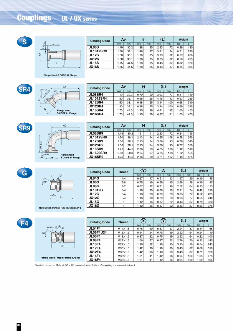
(L)S353735353535
728482828787
130230260265370385
UL08SUL1012SCVUL12SUX12SUL16SUX16S
Catalog Code Weight
30.238.138.138.144.544.5
1.381.461.381.381.381.38
2.833.313.233.233.433.43
0.290.510.570.580.820.85
1.191.501.501.501.751.75
inch mm inch mm inch mm lbs g
Standard product — Material: SS or SC equivalent steel, Surface: Zinc plating or chromate treatment
Flange Head S CODE 61 Flange
SR430.238.138.138.144.544.5
202525252828
77113100100112111
140285310315455475
1.191.501.501.501.751.75
0.790.980.980.981.101.10
3.034.453.943.944.414.37
0.310.630.680.691.001.05
UL08SR4UL1012SR4UL12SR4UX12SR4UL16SR4UX16SR4
Catalog Code Weight(L)inch mm inch mm inch mm lbs g
A
A
A
H
3.94~4.45
2.79~
2.92 45。
Flange HeadS CODE 61 Flange
(L)
(L)
90。SR9
30.238.138.138.144.550.844.5
41545454606760
72108
9393
108108107
155265345350510555525
UL08SR9UL1012SR9UL12SR9UX12SR9UL16SR9UL1620SR9UX16SR9
Catalog Code Weight(L)inch mm inch mm inch mm lbs g
A
H
3.94~4.45
2.79
~2.
92
AFlange HeadS CODE 61 Flange
ThreadG1719223030303636
1/43/81/23/43/43/411
1315182020202222
5058647477778787
4585
115190235240360375
UL04GUL06GUL08GUL1012GUL12GUX12GUL16GUX16G
Catalog Code Weight(L)inch mm inch mm inch mm lbs gG
A
Male British Parallel Pipe Thread(BSPP)
30。
(L)
A
H
H
F4192422273236364141
171919223030303636
57646470808787
100100
65110100145245310320475495
1.191.501.501.501.752.001.75
1.612.132.132.132.362.642.36
2.834.253.663.664.254.254.21
0.340.580.760.771.121.221.16
0.670.750.871.181.181.181.421.42
0.510.590.710.790.790.790.870.87
1.972.282.522.913.033.033.433.43
0.100.190.250.420.520.530.790.83
0.750.940.871.061.261.421.421.611.61
0.670.750.750.871.181.181.181.421.42
2.242.522.522.763.153.433.433.943.94
0.140.240.220.320.540.680.711.051.09
M14×1.5M18×1.5M18×1.5M22×1.5M24×1.5M30×1.5M30×1.5M33×1.5M33×1.5
UL04F4UL06F4U24UL06F4UL08F4UL10F4UL12F4UX12F4UL16F4UX16F4
Catalog Code Thread Weight(L)inch mm inch mm inch mm lbs g
M(P=1.5)
Female MetricThread Female 30°Seat
(L)
30。
A3.
94~
4.45 2.79~2.92
(L)
Y
X Y
Y
YX
F20.750.871.061.061.061.261.421.421.421.611.61
1922272727323636364141
0.670.750.870.870.871.181.181.181.181.421.42
1719222222303030303636
2.172.402.562.642.723.073.113.233.273.623.62
5561656769787982839292
0.140.220.300.330.300.540.610.710.720.981.01
65100135150135245275320325445460
7/16-209/16-183/4-163/4-167/8-147/8-14
1 1/16 -121 1/16 -121 1/16 -121 5/16 -121 5/16 -12
UL04F2UL06F2UL0608F2UL08F2UL0810F2UL10F2UL1012F2UL12F2UX12F2UL16F2UX16F2
Catalog Code Thread Weight(L)inch mm inch mm inch mm lbs g
(L)
37。
UNF
JIC 37° Female
F2R40.750.870.870.871.260.98
19.022.022.022.032.025.4
AABABB
0.540.980.710.941.380.87
13.724.918.023.935.022.0
3.033.623.404.494.653.70
779286
11411894
0.150.280.300.440.440.46
70125135200200210
7/16-209/16-183/4-163/4-167/8-147/8-14
UL04F2R422UL06F2R437UL0608F2R4N18UL08F2R4N31UL0810F2R405UL10F2R4
Catalog Code Thread
Shape
Weight(L)inch mm inch mm inch mm lbs g
JIC 37° Female
37。
45。
H
UNF
(L)
Shape
JIC 37° Female
90。
F2R90.750.870.871.061.001.001.421.251.501.50
19.022.0
2227
25.425.4
3631.838.038.1
AABABBBBBB
0.981.181.771.542.561.733.072.092.482.48
25304539654478536363
2.602.993.193.463.073.354.133.944.254.25
667681887885
105100108108
0.170.280.320.440.440.471.100.741.121.17
75125145200200215500335510530
7/16-209/16-183/4-163/4-167/8-147/8-14
1 1/16 -121 1/16 -121 5/16 -121 5/16 -12
UL04F2R9N25UL06F2R914UL0608F2R964 UL08F2R9N50UL0810F2R911UL10F2R9UL12F2R9N78UX12F2R9UL16F2R9UX16F2R9N63
Catalog Code Thread Weight(L)inch mm inch mm inch mm lbs g
(L)
90。
UNF
H
37。
37。
(L)
Q20.750.871.061.261.261.421.421.421.611.61
19222732323636364141
0.670.750.871.181.061.181.181.181.421.42
17192230273030303636
2.242.482.763.072.993.113.233.233.743.74
57636778767982829595
0.150.240.340.580.530.620.730.741.081.12
70110155265240280330335490510
9/16-181 1/16 -161 3/16 -16
1-141-14
1 3/16 -121 3/16 -121 3/16 -121 7/16 -121 7/16 -12
UL04Q2UL06Q2UL08Q2UL10Q2UL10Q2H27UL1012Q2UL12Q2UX12Q2UL16Q2UX16Q2
Catalog Code Thread Weightinch mm inch mm inch mm lbs g
Female O-Ring Face Seal
UNF (L)
(L)
Standard product — Material: SS or SC equivalent steel, Surface: Zinc plating or chromate treatment
Q2C70.750.871.061.26
19222732
0.670.750.871.06
17192227
2.242.482.643.07
57636778
0.140.230.320.51
65105145230
9/16-1811/16 -1613/16 -16
1-14
UL04Q2C7UL06Q2C7UL08Q2C7UL10Q2H27C7
Catalog Code Thread Weightinch mm inch mm inch mm lbs g
(L)
Short type Flat face
(L)UNF
H
H
UNF
H
<A type>
<B type>
<A type>
<B type>
37。
45。(L)
UNF
H
X
X
X
Y
X Y
X Y
YX
X
X
X
X
YX
YX
30
Couplings UL / UX series

(L)S353735353535
728482828787
130230260265370385
UL08SUL1012SCVUL12SUX12SUL16SUX16S
Catalog Code Weight
30.238.138.138.144.544.5
1.381.461.381.381.381.38
2.833.313.233.233.433.43
0.290.510.570.580.820.85
1.191.501.501.501.751.75
inch mm inch mm inch mm lbs g
Standard product — Material: SS or SC equivalent steel, Surface: Zinc plating or chromate treatment
Flange Head S CODE 61 Flange
SR430.238.138.138.144.544.5
202525252828
77113100100112111
140285310315455475
1.191.501.501.501.751.75
0.790.980.980.981.101.10
3.034.453.943.944.414.37
0.310.630.680.691.001.05
UL08SR4UL1012SR4UL12SR4UX12SR4UL16SR4UX16SR4
Catalog Code Weight(L)inch mm inch mm inch mm lbs g
A
A
A
H
3.94~4.45
2.79~
2.92 45。
Flange HeadS CODE 61 Flange
(L)
(L)
90。SR9
30.238.138.138.144.550.844.5
41545454606760
72108
9393
108108107
155265345350510555525
UL08SR9UL1012SR9UL12SR9UX12SR9UL16SR9UL1620SR9UX16SR9
Catalog Code Weight(L)inch mm inch mm inch mm lbs g
A
H
3.94~4.45
2.79
~2.
92
AFlange HeadS CODE 61 Flange
ThreadG1719223030303636
1/43/81/23/43/43/411
1315182020202222
5058647477778787
4585
115190235240360375
UL04GUL06GUL08GUL1012GUL12GUX12GUL16GUX16G
Catalog Code Weight(L)inch mm inch mm inch mm lbs gG
A
Male British Parallel Pipe Thread(BSPP)
30。
(L)
A
H
H
F4192422273236364141
171919223030303636
57646470808787
100100
65110100145245310320475495
1.191.501.501.501.752.001.75
1.612.132.132.132.362.642.36
2.834.253.663.664.254.254.21
0.340.580.760.771.121.221.16
0.670.750.871.181.181.181.421.42
0.510.590.710.790.790.790.870.87
1.972.282.522.913.033.033.433.43
0.100.190.250.420.520.530.790.83
0.750.940.871.061.261.421.421.611.61
0.670.750.750.871.181.181.181.421.42
2.242.522.522.763.153.433.433.943.94
0.140.240.220.320.540.680.711.051.09
M14×1.5M18×1.5M18×1.5M22×1.5M24×1.5M30×1.5M30×1.5M33×1.5M33×1.5
UL04F4UL06F4U24UL06F4UL08F4UL10F4UL12F4UX12F4UL16F4UX16F4
Catalog Code Thread Weight(L)inch mm inch mm inch mm lbs g
M(P=1.5)
Female MetricThread Female 30°Seat
(L)
30。
A3.
94~
4.45 2.79~2.92
(L)
Y
X Y
Y
YX
F20.750.871.061.061.061.261.421.421.421.611.61
1922272727323636364141
0.670.750.870.870.871.181.181.181.181.421.42
1719222222303030303636
2.172.402.562.642.723.073.113.233.273.623.62
5561656769787982839292
0.140.220.300.330.300.540.610.710.720.981.01
65100135150135245275320325445460
7/16-209/16-183/4-163/4-167/8-147/8-14
1 1/16 -121 1/16 -121 1/16 -121 5/16 -121 5/16 -12
UL04F2UL06F2UL0608F2UL08F2UL0810F2UL10F2UL1012F2UL12F2UX12F2UL16F2UX16F2
Catalog Code Thread Weight(L)inch mm inch mm inch mm lbs g
(L)
37。
UNF
JIC 37° Female
F2R40.750.870.870.871.260.98
19.022.022.022.032.025.4
AABABB
0.540.980.710.941.380.87
13.724.918.023.935.022.0
3.033.623.404.494.653.70
779286
11411894
0.150.280.300.440.440.46
70125135200200210
7/16-209/16-183/4-163/4-167/8-147/8-14
UL04F2R422UL06F2R437UL0608F2R4N18UL08F2R4N31UL0810F2R405UL10F2R4
Catalog Code ThreadShape
Weight(L)inch mm inch mm inch mm lbs g
JIC 37° Female
37。
45。
H
UNF
(L)Shape
JIC 37° Female
90。
F2R90.750.870.871.061.001.001.421.251.501.50
19.022.0
2227
25.425.4
3631.838.038.1
AABABBBBBB
0.981.181.771.542.561.733.072.092.482.48
25304539654478536363
2.602.993.193.463.073.354.133.944.254.25
667681887885
105100108108
0.170.280.320.440.440.471.100.741.121.17
75125145200200215500335510530
7/16-209/16-183/4-163/4-167/8-147/8-14
1 1/16 -121 1/16 -121 5/16 -121 5/16 -12
UL04F2R9N25UL06F2R914UL0608F2R964 UL08F2R9N50UL0810F2R911UL10F2R9UL12F2R9N78UX12F2R9UL16F2R9UX16F2R9N63
Catalog Code Thread Weight(L)inch mm inch mm inch mm lbs g
(L)
90。
UNF
H
37。
37。
(L)
Q20.750.871.061.261.261.421.421.421.611.61
19222732323636364141
0.670.750.871.181.061.181.181.181.421.42
17192230273030303636
2.242.482.763.072.993.113.233.233.743.74
57636778767982829595
0.150.240.340.580.530.620.730.741.081.12
70110155265240280330335490510
9/16-181 1/16 -161 3/16 -16
1-141-14
1 3/16 -121 3/16 -121 3/16 -121 7/16 -121 7/16 -12
UL04Q2UL06Q2UL08Q2UL10Q2UL10Q2H27UL1012Q2UL12Q2UX12Q2UL16Q2UX16Q2
Catalog Code Thread Weightinch mm inch mm inch mm lbs g
Female O-Ring Face Seal
UNF (L)
(L)
Standard product — Material: SS or SC equivalent steel, Surface: Zinc plating or chromate treatment
Q2C70.750.871.061.26
19222732
0.670.750.871.06
17192227
2.242.482.643.07
57636778
0.140.230.320.51
65105145230
9/16-1811/16 -1613/16 -16
1-14
UL04Q2C7UL06Q2C7UL08Q2C7UL10Q2H27C7
Catalog Code Thread Weightinch mm inch mm inch mm lbs g
(L)
Short type Flat face
(L)UNF
H
H
UNF
H
<A type>
<B type>
<A type>
<B type>
37。
45。(L)
UNF
H
X
X
X
Y
X Y
X Y
YX
X
X
X
X
YX
YX
31

45。
Q2R40.750.871.061.261.421.421.421.611.61
192227323636364141
0.430.830.871.021.021.021.021.101.18
112122262626262830
2.873.503.113.824.023.943.864.574.80
73897997
102100
98116122
0.160.300.370.610.660.760.781.201.22
75135170275300345355545555
9/16-181 1/16 -121 3/16 -12
1-141 3/16 -121 3/16 -121 3/16 -121 7/16 -121 7/16 -12
UL04Q2R4UL06Q2R4UL08Q2R4N22UL10Q2R4N26UL1012Q2R408UL12Q2R4UX12Q2R4UL16Q2R421UX16Q2R4
Catalog Code Thread WeightH (L)inch mm inch mm inch mm lbs g
Female O-Ring Face Seal
UNF
H
(L)
Q2R90.750.871.061.261.421.421.421.611.61
192227323636364141
0.911.501.692.171.022.282.282.642.64
233843552658586767
2.362.64.2.953.623.583.623.584.494.49
60677592919291
114114
0.170.300.410.680.750.840.851.331.37
75135185310340380385605620
9/16-181 1/16 -121 3/16 -12
1-141 3/16 -121 3/16 -121 3/16 -121 7/16 -121 7/16 -12
UL04Q2R9UL06Q2R9UL08Q2R9UL10Q2R9UL1012Q2R9N58UL12Q2R9UX12Q2R9UL16Q2R9UX16Q2R9
Catalog Code Thread WeightH (L)inch mm inch mm inch mm lbs g
Female O-Ring Face Seal
UNF
H
(L)
90。
(L)K6368688080
2.482.682.683.153.15
4045455353
1.571.771.772.092.09
2222222828
0.870.870.871.101.10
7992929999
M10M10M10M12M12
3.113.623.623.903.90
0.430.430.430.510.51
1111111313
1.501.852.033.443.47
680840920
1,5601,575
UL08K15 UL12K20UX12K20UL16K25UX16K25
Catalog Code Weightinch mm inch mm inch mm inch mm inch mm lbs g
JIS B 2291 21MPa(210kgf/cm2)Flange
(L)C
2.4
4.1
B
JIS SHABolt dia.
C Bolt dia.BoltA
(L)
Standard product — Material: SS or SC equivalent steel, Surface: Zinc plating or chromate treatment
K25458586868
2.13 2.28 2.28 2.68 2.68
3640404848
1.42 1.57 1.57 1.89 1.89
2222222828
0.87 0.87 0.87 1.10 1.10
7992929999
M10M10M10M12M12
3.11 3.62 3.62 3.90 3.90
0.43 0.43 0.43 0.51 0.51
1111111313
1.10 1.44 1.54 2.36 2.76
500655700
1,0701,250
UL08K215UL12K220UX12K220UL16K225UX16K225
Catalog Code Weightinch mm inch mm inch mm inch mm inch mm lbs g
JIS B 2291 21MPa(210kgf/cm2)Flange
(L)C
2.4
4.1
B
JIS SSABolt dia.
C
B
B Bolt dia.BoltA
X
X
X
X
R0.670.750.870.871.181.181.421.81
1719222230303646
0.510.590.710.710.790.790.870.99
13151818202022
25.2
1.972.282.522.523.073.353.664.80
50586464788593
122
0.110.190.280.280.490.630.951.91
5085
125125220285430865
1/43/81/21/23/43/41
1 1/4
UZ04RUB06RUB08RUZ08RUB1012RUB12RUB16RUZ20R
Catalog Code Thread Weightinch mm inch mm inch mm lbs g
Standard product — Material: SS or SC equivalent steel, Surface: Zinc plating or chromate treatment
A
A
R
Male British Tapered Pipe Thread(BSPT)
(L)
F0.750.871.061.061.421.421.611.97
1922272736364150
0.670.750.870.871.181.181.421.81
1719222230303646
2.202.442.642.643.273.583.905.04
56626767839199
128
0.150.220.320.320.640.791.142.13
70100145145290360515965
1/43/81/21/23/43/41
1 1/4
UZ04FUB06FUB08FUZ08FUB1012FUB12FUB16FUZ20F
Catalog Code Thread Weightinch mm inch mm inch mm lbs g
(L)
30。
C0.750.871.061.061.421.061.421.611.97
192227273627364150
0.670.750.870.871.181.061.181.421.81
171922223027303646
2.202.442.642.643.273.033.543.90
5.04
5662676783779199
128
0.150.230.330.330.650.460.801.152.16
70105150150295210365520980
1/43/81/21/23/41/23/41
1 1/4
UZ04CUB06CUB08CUZ08CUB1012CUB1008CH27UB12CUB16CUZ20C
Catalog Code Thread Weightinch mm inch mm inch mm lbs g
(L)
Female British Parallel Pipe Thread Male 30°Seat(BSPOR)
G
(L)
30。
H
G
CR40.750.871.061.061.421.421.611.97
1922272736364150
0.941.020.870.871.141.141.301.49
24262222292933
37.9
3.033.434.724.413.984.415.166.30
7787
120112101112131160
0.170.280.460.460.760.911.412.66
75125210210345415640
1,205
1/43/81/21/23/43/41
1 1/4
UZ04CR4UB06CR4UB08CR4UZ08CR4UB1012CR4UB12CR4UB16CR4UZ20CR4
Catalog Code Thread Weightinch mm inch mm inch mm lbs g
Female British Parallel Pipe Thread Male 30°Seat(BSPOR)
(L)(L)
45。
30。
H
G
CR60.75 0.87
1922
0.63 1.06
1627
2.64 3.31
6784
0.18 0.26
80120
1/43/8
UZ04CR6N16UB06CR6N27
Catalog Code Thread Weightinch mm inch mm inch mm lbs g
Female British Parallel Pipe Thread Male 30°Seat(BSPOR)
(L)(L)
60。
30。
CR90.750.871.061.061.421.421.611.97
1922272736364150
0.941.501.811.812.362.362.763.15
2438464660607080
2.362.643.703.393.744.024.725.83
6067948695
102120148
0.170.280.460.460.840.981.552.92
75125210210380445705
1,325
1/43/81/21/23/43/41
1 1/4
UZ04CR9UB06CR9UB08CR9UZ08CR9UB1012CR9UB12CR9UB16CR9UZ20CR9
Catalog Code Thread Weightinch mm inch mm inch mm lbs g
Female British Parallel Pipe Thread Male 30°Seat(BSPOR)
(L)90。
F
H
(L)
(L)
G
Female Japanese Industrial PipeThread (JIS) Female 30°Seat
30。
(L)
Y
YX
YX
X
X
X
H
H
H
Y
Y
X
YX
X
X
X
32
Couplings UL / UX series

45。
Q2R40.750.871.061.261.421.421.421.611.61
192227323636364141
0.430.830.871.021.021.021.021.101.18
112122262626262830
2.873.503.113.824.023.943.864.574.80
73897997
102100
98116122
0.160.300.370.610.660.760.781.201.22
75135170275300345355545555
9/16-181 1/16 -121 3/16 -12
1-141 3/16 -121 3/16 -121 3/16 -121 7/16 -121 7/16 -12
UL04Q2R4UL06Q2R4UL08Q2R4N22UL10Q2R4N26UL1012Q2R408UL12Q2R4UX12Q2R4UL16Q2R421UX16Q2R4
Catalog Code Thread WeightH (L)inch mm inch mm inch mm lbs g
Female O-Ring Face Seal
UNF
H
(L)
Q2R90.750.871.061.261.421.421.421.611.61
192227323636364141
0.911.501.692.171.022.282.282.642.64
233843552658586767
2.362.64
.2.953.623.583.623.584.494.49
60677592919291
114114
0.170.300.410.680.750.840.851.331.37
75135185310340380385605620
9/16-181 1/16 -121 3/16 -12
1-141 3/16 -121 3/16 -121 3/16 -121 7/16 -121 7/16 -12
UL04Q2R9UL06Q2R9UL08Q2R9UL10Q2R9UL1012Q2R9N58UL12Q2R9UX12Q2R9UL16Q2R9UX16Q2R9
Catalog Code Thread WeightH (L)inch mm inch mm inch mm lbs g
Female O-Ring Face Seal
UNF
H
(L)
90。
(L)K6368688080
2.482.682.683.153.15
4045455353
1.571.771.772.092.09
2222222828
0.870.870.871.101.10
7992929999
M10M10M10M12M12
3.113.623.623.903.90
0.430.430.430.510.51
1111111313
1.501.852.033.443.47
680840920
1,5601,575
UL08K15 UL12K20UX12K20UL16K25UX16K25
Catalog Code Weightinch mm inch mm inch mm inch mm inch mm lbs g
JIS B 2291 21MPa(210kgf/cm2)Flange
(L)C
2.4
4.1
B
JIS SHABolt dia.
C Bolt dia.BoltA
(L)
Standard product — Material: SS or SC equivalent steel, Surface: Zinc plating or chromate treatment
K25458586868
2.13 2.28 2.28 2.68 2.68
3640404848
1.42 1.57 1.57 1.89 1.89
2222222828
0.87 0.87 0.87 1.10 1.10
7992929999
M10M10M10M12M12
3.11 3.62 3.62 3.90 3.90
0.43 0.43 0.43 0.51 0.51
1111111313
1.10 1.44 1.54 2.36 2.76
500655700
1,0701,250
UL08K215UL12K220UX12K220UL16K225UX16K225
Catalog Code Weightinch mm inch mm inch mm inch mm inch mm lbs g
JIS B 2291 21MPa(210kgf/cm2)Flange
(L)C
2.4
4.1
B
JIS SSABolt dia.
C
B
B Bolt dia.BoltA
X
X
X
X
R0.670.750.870.871.181.181.421.81
1719222230303646
0.510.590.710.710.790.790.870.99
13151818202022
25.2
1.972.282.522.523.073.353.664.80
50586464788593
122
0.110.190.280.280.490.630.951.91
5085
125125220285430865
1/43/81/21/23/43/41
1 1/4
UZ04RUB06RUB08RUZ08RUB1012RUB12RUB16RUZ20R
Catalog Code Thread Weightinch mm inch mm inch mm lbs g
Standard product — Material: SS or SC equivalent steel, Surface: Zinc plating or chromate treatment
A
A
R
Male British Tapered Pipe Thread(BSPT)
(L)
F0.750.871.061.061.421.421.611.97
1922272736364150
0.670.750.870.871.181.181.421.81
1719222230303646
2.202.442.642.643.273.583.905.04
56626767839199
128
0.150.220.320.320.640.791.142.13
70100145145290360515965
1/43/81/21/23/43/41
1 1/4
UZ04FUB06FUB08FUZ08FUB1012FUB12FUB16FUZ20F
Catalog Code Thread Weightinch mm inch mm inch mm lbs g
(L)
30。
C0.750.871.061.061.421.061.421.611.97
192227273627364150
0.670.750.870.871.181.061.181.421.81
171922223027303646
2.202.442.642.643.273.033.543.90
5.04
5662676783779199
128
0.150.230.330.330.650.460.801.152.16
70105150150295210365520980
1/43/81/21/23/41/23/41
1 1/4
UZ04CUB06CUB08CUZ08CUB1012CUB1008CH27UB12CUB16CUZ20C
Catalog Code Thread Weightinch mm inch mm inch mm lbs g
(L)
Female British Parallel Pipe Thread Male 30°Seat(BSPOR)
G
(L)
30。
H
G
CR40.750.871.061.061.421.421.611.97
1922272736364150
0.941.020.870.871.141.141.301.49
24262222292933
37.9
3.033.434.724.413.984.415.166.30
7787
120112101112131160
0.170.280.460.460.760.911.412.66
75125210210345415640
1,205
1/43/81/21/23/43/41
1 1/4
UZ04CR4UB06CR4UB08CR4UZ08CR4UB1012CR4UB12CR4UB16CR4UZ20CR4
Catalog Code Thread Weightinch mm inch mm inch mm lbs g
Female British Parallel Pipe Thread Male 30°Seat(BSPOR)
(L)(L)
45。
30。
H
G
CR60.75 0.87
1922
0.63 1.06
1627
2.64 3.31
6784
0.18 0.26
80120
1/43/8
UZ04CR6N16UB06CR6N27
Catalog Code Thread Weightinch mm inch mm inch mm lbs g
Female British Parallel Pipe Thread Male 30°Seat(BSPOR)
(L)(L)
60。
30。
CR90.750.871.061.061.421.421.611.97
1922272736364150
0.941.501.811.812.362.362.763.15
2438464660607080
2.362.643.703.393.744.024.725.83
6067948695
102120148
0.170.280.460.460.840.981.552.92
75125210210380445705
1,325
1/43/81/21/23/43/41
1 1/4
UZ04CR9UB06CR9UB08CR9UZ08CR9UB1012CR9UB12CR9UB16CR9UZ20CR9
Catalog Code Thread Weightinch mm inch mm inch mm lbs g
Female British Parallel Pipe Thread Male 30°Seat(BSPOR)
(L)90。
F
H
(L)
(L)
G
Female Japanese Industrial PipeThread (JIS) Female 30°Seat
30。
(L)
Y
YX
YX
X
X
X
H
H
H
Y
Y
X
YX
X
X
X
Couplings
33
UB / UZ series

(L)S1.381.421.381.381.381.811.381.381.381.381.741.62
35363535354635353535
44.141.1
2.832.872.833.273.544.023.543.663.663.664.844.84
7273728390
10290939393
123123
0.300.350.310.510.670.640.730.960.891.012.092.00
135160140230305290330435405460950905
UB08SUB0812SUZ08SUB1012SUB12SUB1208SUB1216SUB16SUB1612SUB1620SUB20SUZ20S
Catalog Code Weight
1.191.501.191.501.501.191.751.751.502.002.002.00
inch mm inch mm inch mm lbs gA
Flange Head S CODE 61 Flange
(L)H1.571.381.381.651.501.341.652.002.00
40353542383442
50.850.8
2.992.873.543.823.823.623.945.125.12
767390979792
100130130
0.370.530.710.851.060.941.202.402.31
170240320385480425545
1,0901,050
UB08HUB1012HUB12HUB1216HUB16HUB1612HUB1620HUB20HUZ20H
Catalog Code Weightinch mm inch mm inch mm lbs g
A
Flange Head H CODE 62 Flange
SR40.79 1.10 1.10 0.79 0.98 0.98 2.05 0.98 1.10 1.10 1.57 2.05 1.10 1.18 1.18
202828202525522528284052283030
3.03 2.44 3.90 3.03 4.57 4.25 5.55 4.33 4.49 4.61 5.08 5.87 4.61 5.63 5.63
77629977
116108141110114117129149117143143
0.32 0.44 0.49 0.32 0.67 0.77 0.93 0.68 0.86 1.16 1.22 1.27 1.21 2.05 1.96
145200220145305350420310390525555575550930890
UB08SR4UB0812SR4N28UB1008SR4N28UZ08SR4UB1012SR4UB12SR4UB12SR4N52UB1208SR4N25UB1216SR4N28UB16SR4UB16SR4N40UB1612SR4N52UB1620SR4N28UB20SR4UZ20SR4
Catalog Code Weight(L)inch mm inch mm inch mm lbs g
A
A
H
3.94~4.45
2.79~
2.92 45。
Flange Head S CODE 61 Flange
(L)
H
H
SR91.612.171.653.542.361.612.133.542.133.945.912.052.363.545.912.363.864.722.362.643.542.642.64
415542906041549054
100150
526090
1506098
1206067906767
2.833.393.273.433.392.833.663.273.985.555.553.943.983.985.554.454.454.454.454.494.455.755.75
7286838786729383
101141141100101101141113113113113114113146146
0.350.470.470.680.430.350.640.580.861.181.360.730.941.051.361.271.481.581.191.381.432.372.28
160215215310195160290265390535615330425475615575670715540625650
1,0751,035
UB08SR9UB0812SR9N55UB1008SR9UB08SR970UB08SR9N60UZ08SR9UB1012SR9UB1008SR9N90UB12SR9UB12SR9N100UB12SR9N150UB1208SR9N52UB1216SR9UB1216SR9N90UB12SR9N150UB16SR9UB16SR9N98UB16SR9N120UB1612SR9N60UB1620SR9UB16SR9N90UB20SR9UZ20SR9
Catalog Code Weight(L)inch mm inch mm inch mm lbs g
A
(L)
90。
H
3.94~4.45
2.79
~2.
92
A
Flange Head S CODE 61 Flange
1.251.631.631.881.881.632.132.132.13
1.191.501.191.191.501.501.501.191.751.751.751.502.002.002.00
1.191.501.191.191.191.191.501.191.501.501.501.191.751.751.501.751.751.751.502.001.752.002.00
30.238.130.238.138.130.244.544.538.150.850.850.8
31.841.341.347.647.641.354.054.054.0
30.238.130.230.238.138.138.130.244.544.544.538.150.850.850.8
30.238.130.230.230.230.238.130.238.138.138.130.244.544.538.144.544.544.538.150.844.550.850.8
Standard product — Material: SS or SC equivalent steel, Surface: Zinc plating or chromate treatment
A3.
94~
4.45 2.79~2.92
(L)
A3.
94~
4.4
5
2.79~2.92
(L)
ThreadG0.670.750.870.871.181.181.421.81
1719222230303646
1/43/81/21/23/43/41
1 1/4
0.510.590.710.710.790.790.870.99
13151818202022
25.2
1.972.282.522.523.073.353.664.80
50586464788593
122
0.110.190.260.260.470.620.941.90
5085
120120215280425860
UZ04GUB06GUB08GUZ08GUB1012GUB12GUB16GUZ20G
Catalog Code Weightinch mm inch mm inch mm lbs gG
A
Male British Parallel Pipe Thread(BSPP)
30。
(L)
A
F40.750.940.871.061.061.261.421.611.97
192422272732364150
0.670.750.750.870.871.181.181.611.81
171919222230304146
2.242.522.522.762.763.313.744.175.12
57646470708495
106130
0.150.240.220.330.330.600.781.201.76
70110100150150270355545800
M14×1.5M18×1.5M18×1.5M22×1.5M22×1.5M24×1.5M30×1.5M33×1.5M36×1.5
UZ04F4UB06F4U24UB06F4UB08F4UZ08F4UB10F4UB12F4UB16F4UZ20F4
Catalog Code Thread Weightinch mm inch mm inch mm lbs g
M(P=1.5)
Female MetricThread Female 30°Seat
(L)
30。
(L)
(L)
F20.750.870.871.061.061.061.061.061.421.261.421.421.611.421.97
192222272727272736323636413650
0.670.750.750.870.870.870.870.871.181.181.181.181.421.421.81
171919222222222230303030363646
2.172.322.442.562.642.722.642.722.953.193.273.583.863.705.04
5559626567696769758183919894
128
0.140.190.230.310.350.400.350.400.570.590.660.791.121.082.13
6585
105140160145160145260270300360510490965
7/16-209/16-18 9/16-183/4-163/4-167/8-143/4-167/8-14
1 1/16 -127/8-14
1 1/16 -121 1/16 -121 5/16 -121 1/16 -121 5/8 -12
UZ04F2UZ0406F2UB06F2UB0608F2UB08F2UB0810F2UZ08F2UZ0810F2UB0812F2UB10F2UB1012F2UB12F2UB16F2UB1612F2UZ20F2
Catalog Code Thread Weight(L)inch mm inch mm inch mm lbs g
(L)
37。
UNF
JIC 37° Female
Standard product — Material: SS or SC equivalent steel, Surface: Zinc plating or chromate treatment
HR931.841.341.341.341.347.647.647.647.654.054.047.654.054.0
1.251.631.631.631.631.881.881.881.882.132.131.882.132.13
1.692.172.282.283.942.872.873.544.532.603.543.943.903.90
43555858
100737390
1156690
1009999
2.833.983.983.984.064.334.454.454.454.454.454.576.026.02
72101101101103110113113113113113116153153
0.390.730.740.901.091.121.411.511.631.521.641.753.163.06
175330335410495510640685740690745795
1,4351,390
UB08HR9UB1012HR9N55UB1012HR9UB12HR9UB12HR9N100UB1216HR9N73UB16HR9UB16HR9N90UB16HR9N115UB1620HR9N66UB1620HR9N90UB16HR917UB20HR9UZ20HR9
Catalog Code Weight(L)mminch mm inch mm inch mm lbs g
A
(L)
90。
H
3.94~4.45
2.79
~2.
92
AFlange HeadS CODE 62 Flange
HR41.251.631.881.882.132.132.13
31.841.347.647.654.054.054.0
0.831.022.051.341.571.381.38
21265234403535
3.114.335.045.005.876.226.22
79110128127149158158
0.350.831.111.251.912.742.66
160375505565865
1,2451,205
UB08HR4UB12HR4UB1216HR4N52UB16HR4UB1620HR4N40UB20HR4UZ20HR4
Catalog Code Weight(L)inch mm inch mm inch mm lbs g
A
A
H
3.94~4.45
2.79~
2.92 45。
Flange HeadS CODE 62 Flange
(L)
H
H
Y
Y
X
YX
Y
YX
YX
34
Couplings UB / UZ series

(L)S1.381.421.381.381.381.811.381.381.381.381.741.62
35363535354635353535
44.141.1
2.832.872.833.273.544.023.543.663.663.664.844.84
7273728390
10290939393
123123
0.300.350.310.510.670.640.730.960.891.012.092.00
135160140230305290330435405460950905
UB08SUB0812SUZ08SUB1012SUB12SUB1208SUB1216SUB16SUB1612SUB1620SUB20SUZ20S
Catalog Code Weight
1.191.501.191.501.501.191.751.751.502.002.002.00
inch mm inch mm inch mm lbs gA
Flange Head S CODE 61 Flange
(L)H1.571.381.381.651.501.341.652.002.00
40353542383442
50.850.8
2.992.873.543.823.823.623.945.125.12
767390979792
100130130
0.370.530.710.851.060.941.202.402.31
170240320385480425545
1,0901,050
UB08HUB1012HUB12HUB1216HUB16HUB1612HUB1620HUB20HUZ20H
Catalog Code Weightinch mm inch mm inch mm lbs g
A
Flange Head H CODE 62 Flange
SR40.79 1.10 1.10 0.79 0.98 0.98 2.05 0.98 1.10 1.10 1.57 2.05 1.10 1.18 1.18
202828202525522528284052283030
3.03 2.44 3.90 3.03 4.57 4.25 5.55 4.33 4.49 4.61 5.08 5.87 4.61 5.63 5.63
77629977
116108141110114117129149117143143
0.32 0.44 0.49 0.32 0.67 0.77 0.93 0.68 0.86 1.16 1.22 1.27 1.21 2.05 1.96
145200220145305350420310390525555575550930890
UB08SR4UB0812SR4N28UB1008SR4N28UZ08SR4UB1012SR4UB12SR4UB12SR4N52UB1208SR4N25UB1216SR4N28UB16SR4UB16SR4N40UB1612SR4N52UB1620SR4N28UB20SR4UZ20SR4
Catalog Code Weight(L)inch mm inch mm inch mm lbs g
A
A
H
3.94~4.45
2.79~
2.92 45。
Flange Head S CODE 61 Flange
(L)
H
H
SR91.612.171.653.542.361.612.133.542.133.945.912.052.363.545.912.363.864.722.362.643.542.642.64
415542906041549054
100150
526090
1506098
1206067906767
2.833.393.273.433.392.833.663.273.985.555.553.943.983.985.554.454.454.454.454.494.455.755.75
7286838786729383
101141141100101101141113113113113114113146146
0.350.470.470.680.430.350.640.580.861.181.360.730.941.051.361.271.481.581.191.381.432.372.28
160215215310195160290265390535615330425475615575670715540625650
1,0751,035
UB08SR9UB0812SR9N55UB1008SR9UB08SR970UB08SR9N60UZ08SR9UB1012SR9UB1008SR9N90UB12SR9UB12SR9N100UB12SR9N150UB1208SR9N52UB1216SR9UB1216SR9N90UB12SR9N150UB16SR9UB16SR9N98UB16SR9N120UB1612SR9N60UB1620SR9UB16SR9N90UB20SR9UZ20SR9
Catalog Code Weight(L)inch mm inch mm inch mm lbs g
A
(L)
90。
H
3.94~4.45
2.79
~2.
92
A
Flange Head S CODE 61 Flange
1.251.631.631.881.881.632.132.132.13
1.191.501.191.191.501.501.501.191.751.751.751.502.002.002.00
1.191.501.191.191.191.191.501.191.501.501.501.191.751.751.501.751.751.751.502.001.752.002.00
30.238.130.238.138.130.244.544.538.150.850.850.8
31.841.341.347.647.641.354.054.054.0
30.238.130.230.238.138.138.130.244.544.544.538.150.850.850.8
30.238.130.230.230.230.238.130.238.138.138.130.244.544.538.144.544.544.538.150.844.550.850.8
Standard product — Material: SS or SC equivalent steel, Surface: Zinc plating or chromate treatment
A3.
94~
4.45 2.79~2.92
(L)
A3.
94~
4.4
5
2.79~2.92
(L)
ThreadG0.670.750.870.871.181.181.421.81
1719222230303646
1/43/81/21/23/43/41
1 1/4
0.510.590.710.710.790.790.870.99
13151818202022
25.2
1.972.282.522.523.073.353.664.80
50586464788593
122
0.110.190.260.260.470.620.941.90
5085
120120215280425860
UZ04GUB06GUB08GUZ08GUB1012GUB12GUB16GUZ20G
Catalog Code Weightinch mm inch mm inch mm lbs gG
A
Male British Parallel Pipe Thread(BSPP)
30。
(L)
A
F40.750.940.871.061.061.261.421.611.97
192422272732364150
0.670.750.750.870.871.181.181.611.81
171919222230304146
2.242.522.522.762.763.313.744.175.12
57646470708495
106130
0.150.240.220.330.330.600.781.201.76
70110100150150270355545800
M14×1.5M18×1.5M18×1.5M22×1.5M22×1.5M24×1.5M30×1.5M33×1.5M36×1.5
UZ04F4UB06F4U24UB06F4UB08F4UZ08F4UB10F4UB12F4UB16F4UZ20F4
Catalog Code Thread Weightinch mm inch mm inch mm lbs g
M(P=1.5)
Female MetricThread Female 30°Seat
(L)
30。
(L)
(L)
F20.750.870.871.061.061.061.061.061.421.261.421.421.611.421.97
192222272727272736323636413650
0.670.750.750.870.870.870.870.871.181.181.181.181.421.421.81
171919222222222230303030363646
2.172.322.442.562.642.722.642.722.953.193.273.583.863.705.04
5559626567696769758183919894
128
0.140.190.230.310.350.400.350.400.570.590.660.791.121.082.13
6585
105140160145160145260270300360510490965
7/16-209/16-18 9/16-183/4-163/4-167/8-143/4-167/8-14
1 1/16 -127/8-14
1 1/16 -121 1/16 -121 5/16 -121 1/16 -121 5/8 -12
UZ04F2UZ0406F2UB06F2UB0608F2UB08F2UB0810F2UZ08F2UZ0810F2UB0812F2UB10F2UB1012F2UB12F2UB16F2UB1612F2UZ20F2
Catalog Code Thread Weight(L)inch mm inch mm inch mm lbs g
(L)
37。
UNF
JIC 37° Female
Standard product — Material: SS or SC equivalent steel, Surface: Zinc plating or chromate treatment
HR931.841.341.341.341.347.647.647.647.654.054.047.654.054.0
1.251.631.631.631.631.881.881.881.882.132.131.882.132.13
1.692.172.282.283.942.872.873.544.532.603.543.943.903.90
43555858
100737390
1156690
1009999
2.833.983.983.984.064.334.454.454.454.454.454.576.026.02
72101101101103110113113113113113116153153
0.390.730.740.901.091.121.411.511.631.521.641.753.163.06
175330335410495510640685740690745795
1,4351,390
UB08HR9UB1012HR9N55UB1012HR9UB12HR9UB12HR9N100UB1216HR9N73UB16HR9UB16HR9N90UB16HR9N115UB1620HR9N66UB1620HR9N90UB16HR917UB20HR9UZ20HR9
Catalog Code Weight(L)mminch mm inch mm inch mm lbs g
A
(L)
90。
H
3.94~4.45
2.79
~2.
92
AFlange HeadS CODE 62 Flange
HR41.251.631.881.882.132.132.13
31.841.347.647.654.054.054.0
0.831.022.051.341.571.381.38
21265234403535
3.114.335.045.005.876.226.22
79110128127149158158
0.350.831.111.251.912.742.66
160375505565865
1,2451,205
UB08HR4UB12HR4UB1216HR4N52UB16HR4UB1620HR4N40UB20HR4UZ20HR4
Catalog Code Weight(L)inch mm inch mm inch mm lbs g
A
A
H3.94~4.45
2.79~
2.92 45。
Flange HeadS CODE 62 Flange
(L)
H
H
Y
Y
X
YX
Y
YX
YX
35

ThreadQ1.06 271/2 0.43 11 2.64 67 0.37 170UB08Q
Catalog Code Weightinch mm inch mm inch mm lbs g
A (L)
F2R40.750.871.060.871.060.871.421.612.00
1922272227223641
50.8
0.540.980.710.940.710.941.381.571.50
13.724.9
1823.9
1823.9
3540
38.2
3.033.624.254.494.254.495.045.877.83
7792
108114108114128149199
0.150.290.440.440.440.441.111.913.04
70130200200200200505865
1,380
7/16-209/16-183/4-163/4-163/4-163/4-16
1 1/16 -121 5/16 -121 5/8 -12
UZ04F2R422UB06F2R437UB08F2R4N18UB08F2R4N23UZ08F2R4N18UZ08F2R4N23UB12F2R4N45UB16F2R409UZ20F2R4N38
Catalog Code Thread Weight(L)inch mm inch mm inch mm lbs g
JIC 37° Female
37。
45。
H
UNF
(L)
H
Q20.750.871.061.061.261.261.421.421.611.611.971.97
192227273232363641415050
0.670.750.870.871.181.061.181.181.421.421.811.97
171922223027303036364650
2.242.482.642.643.233.153.233.543.863.984.925.16
576367678280829098
101125131
0.170.250.360.360.630.580.670.831.041.232.343.00
75115165165285265305375470560
1,0601,360
UZ04Q2UB06Q2UB08Q2UZ08Q2UB10Q2UB10Q2H27UB1012Q2UB12Q2UB1216Q2UB16Q2UZ20Q2UB20Q2
Catalog Code Thread Weightinch mm inch mm inch mm lbs g
Female O-Ring Face Seal
UNF (L)
(L)
Q2C70.750.871.061.061.26
1922272732
0.670.750.870.871.06
1719222227
2.242.482.642.643.23
5763676782
0.150.230.340.340.56
70105155155255
9/16-1811/16-1613/16-1613/16-16
1-14
UZ04Q2C7UB06Q2C7UB08Q2C7UZ08Q2C7UB10Q2H27C7
Catalog Code Thread Weightinch mm inch mm inch mm lbs g
(L)
Short type Flat face
(L)UNF
Equipped with safety hole
A (L)
GRounded
Standard product — Material: SS or SC equivalent steel, Surface: Zinc plating or chromate treatment
37。
90。
F2R90.750.871.061.061.061.061.061.061.421.502.00
19222727272727273638
50.8
0.981.181.541.541.541.542.172.362.522.483.07
253039
39.239395560646378
2.603.463.703.703.503.503.703.464.454.496.89
6688949489899488
113114175
0.170.280.350.350.350.470.510.581.201.283.13
75125160160160215230265545580
1,420
7/16-209/16-183/4-163/4-163/4-163/4-167/18-147/8-14
1 1/16 -121 5/16 -121 5/8 -12
9/16-1811/16-1613/16-1613/16-16
1-141-14
1 3/16 -121 3/16 -121 7/16 -121 7/16 -121 11/16 -121 11/16 -12
UZ04F2R9N25UB06F2R914UB08F2R9N39UZ08F2R9N39UB08F2R9N50UZ08F2R9N50UB0810F2R986UB10F2R931UB12F2R9N78UB16F2R9UZ20F2R9N78
Catalog Code Thread Weight(L)inch mm inch mm inch mm lbs g
UNF
H
JIC 37° Female
(L)
H
R10.670.750.750.870.871.181.181.42
1719192222303036
0.560.560.560.750.750.750.750.94
14.314.314.319.019.019.019.023.9
2.052.132.242.482.562.872.993.50
5254576365737689
0.110.140.190.240.280.490.630.97
506585
110125220285440
1/43/83/81/21/23/43/41
UZ04R1UB0406R1UB06R1UB0608R1UB08R1UB1012R1UB12R1UB16R1
Catalog Code Thread Weightinch mm inch mm inch mm lbs g
A
A
R
NPTF Male
(L)
(L)
X
X
Y
Y
Y
X
YX
Y
Y
Y
Y
X
X
X
X
Standard product — Material: SS or SC equivalent steel, Surface: Zinc plating or chromate treatment
(L)K636368809090
100
2.482.482.683.153.543.543.94
40404553636370
1.571.571.772.092.482.482.76
22222228282836
0.870.870.871.101.101.101.42
7979
100105138138162
M10M10M10M12M12M12M16
3.113.113.944.135.435.436.38
2.482.482.683.153.543.543.94
1.571.571.772.092.482.482.76
0.870.870.871.101.101.101.42
3.113.113.944.135.435.436.38
0.430.430.430.510.510.510.71
11111113131318
1.521.522.033.585.365.278.07
690690920
1,6252,4302,3903,660
UB08K15 UZ08K15 UB12K20 UB16K25 UB20K32UZ20K32UB24K40
Catalog Code Weightinch mm inch mm inch mm inch mm inch mm lbs g
JIS B 2291 21MPa(210kgf/cm2)Flange
(L)C
2.4
4.1
B
JIS SHABolt dia.
C Bolt dia.BoltA
(L)K1636368809090
100
40404553636370
22222228282836
7979
100105138138162
M10M10M10M12M12M12M16
0.430.430.430.510.510.510.71
11111113131318
1.521.522.093.405.405.298.09
690690950
1,5402,4502,4003,670
UB08K115UZ08K115UB12K120UB16K125UB20K132UZ20K132UB24K140
Catalog Code Weightinch mm inch mm inch mm inch mm inch mm lbs g
JIS B 2291 21MPa(210kgf/cm2)Flange
(L)C
B
JIS SHBBolt dia.
C Bolt dia.BoltA
(L)K254545868767692
2.132.132.282.682.992.993.62
36364048565665
1.421.421.571.892.202.202.56
22222228282836
0.870.870.871.101.101.101.42
7979
100105138138162
M10M10M10M12M12M12M16
3.113.113.944.135.435.436.38
2.132.132.282.682.992.993.62
1.421.421.571.892.202.202.44
0.870.870.871.101.101.101.42
3.113.113.944.135.435.436.38
0.430.430.430.510.510.510.71
11111113131318
1.371.371.542.514.284.197.45
620620700
1,1401,9401,9003,380
UB08K215 UZ08K215 UB12K220 UB16K225 UB20K232 UZ20K232UB24K240
Catalog Code Weightinch mm inch mm inch mm inch mm inch mm lbs g
JIS B 2291 21MPa(210kgf/cm2)Flange
(L)C
2.4
4.1
B
JIS SSABolt dia.
C Bolt dia.BoltA
AA
(L)K354545868767692
36364048565662
22222228282836
7979
100105138138162
M10M10M10M12M12M12M16
550550760
1,1901,9801,9303,390
1.211.211.682.624.374.257.47
UB08K315UZ08K315UB12K320UB16K325UB20K332UZ20K332UB24K340
Catalog Code Weightinch mm inch mm inch mm inch mm lbs g
JIS B 2291 21MPa(210kgf/cm2)Flange
(L)C
B
JIS SSBBolt dia.
C BoltA
B
B
B
B
A
Q2R40.750.871.061.061.261.421.421.611.971.97
19222727323636415050
0.430.830.870.871.021.021.021.181.571.57
11212222262626304040
2.873.503.233.233.984.174.255.006.226.22
73898282
101106108127158158
0.170.310.390.390.660.720.861.332.292.67
75140175175300325390605
1,0401,210
9/16-1811/16-1613/16-1613/16-16
1-141 3/16 -121 3/16 -121 7/16 -121 11/16 -121 11/16 -12
UZ04Q2R4UB06Q2R4UB08Q2R4UZ08Q2R4N22UB10Q2R4N26UB1012Q2R408UB12Q2R4UB16Q2R4UB20Q2R4N40UZ20Q2R4
Catalog Code Thread WeightH (L)inch mm inch mm inch mm lbs g
Female O-Ring Face Seal
Q2R90.750.871.061.061.261.421.421.421.611.971.97
1922272732363636415050
0.911.501.691.692.172.282.282.872.643.942.91
233843435558587367
10074
2.362.642.952.953.783.623.943.904.726.026.02
606775759692
10099
120153153
0.180.310.430.430.730.800.940.971.482.432.93
80140195195330365425440670
1,1001,330
9/16-1811/16-1613/16-1613/16-16
1-141 3/16 -121 3/16 -121 3/16 -121 7/16 -121 11/16 -121 11/16 -12
UZ04Q2R9UB06Q2R9UB08Q2R9UZ08Q2R9UB10Q2R9UB1012Q2R9N58UB12Q2R9UB12Q2R9N73UB16Q2R9UB20Q2R9N100UZ20Q2R9
Catalog Code Thread WeightH (L)inch mm inch mm inch mm lbs g
Female O-Ring Face Seal
UNF
H
(L)
90。
X
X
X
45。UNF
H
(L)
X
A
36
Couplings UB / UZ series
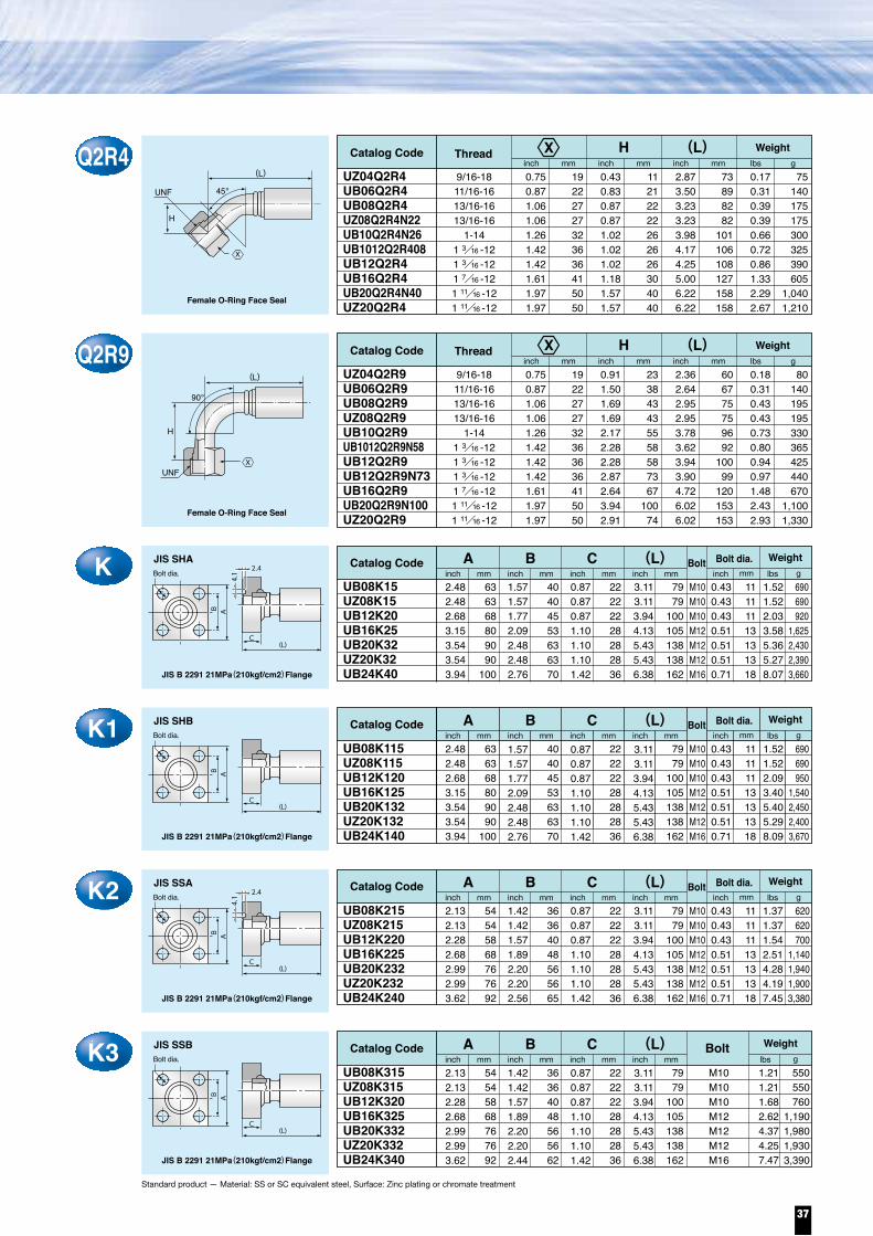
ThreadQ1.06 271/2 0.43 11 2.64 67 0.37 170UB08Q
Catalog Code Weightinch mm inch mm inch mm lbs g
A (L)
F2R40.750.871.060.871.060.871.421.612.00
1922272227223641
50.8
0.540.980.710.940.710.941.381.571.50
13.724.9
1823.9
1823.9
3540
38.2
3.033.624.254.494.254.495.045.877.83
7792
108114108114128149199
0.150.290.440.440.440.441.111.913.04
70130200200200200505865
1,380
7/16-209/16-183/4-163/4-163/4-163/4-16
1 1/16 -121 5/16 -121 5/8 -12
UZ04F2R422UB06F2R437UB08F2R4N18UB08F2R4N23UZ08F2R4N18UZ08F2R4N23UB12F2R4N45UB16F2R409UZ20F2R4N38
Catalog Code Thread Weight(L)inch mm inch mm inch mm lbs g
JIC 37° Female
37。
45。
H
UNF
(L)
H
Q20.750.871.061.061.261.261.421.421.611.611.971.97
192227273232363641415050
0.670.750.870.871.181.061.181.181.421.421.811.97
171922223027303036364650
2.242.482.642.643.233.153.233.543.863.984.925.16
576367678280829098
101125131
0.170.250.360.360.630.580.670.831.041.232.343.00
75115165165285265305375470560
1,0601,360
UZ04Q2UB06Q2UB08Q2UZ08Q2UB10Q2UB10Q2H27UB1012Q2UB12Q2UB1216Q2UB16Q2UZ20Q2UB20Q2
Catalog Code Thread Weightinch mm inch mm inch mm lbs g
Female O-Ring Face Seal
UNF (L)
(L)
Q2C70.750.871.061.061.26
1922272732
0.670.750.870.871.06
1719222227
2.242.482.642.643.23
5763676782
0.150.230.340.340.56
70105155155255
9/16-1811/16-1613/16-1613/16-16
1-14
UZ04Q2C7UB06Q2C7UB08Q2C7UZ08Q2C7UB10Q2H27C7
Catalog Code Thread Weightinch mm inch mm inch mm lbs g
(L)
Short type Flat face
(L)UNF
Equipped with safety hole
A (L)
GRounded
Standard product — Material: SS or SC equivalent steel, Surface: Zinc plating or chromate treatment
37。
90。
F2R90.750.871.061.061.061.061.061.061.421.502.00
19222727272727273638
50.8
0.981.181.541.541.541.542.172.362.522.483.07
253039
39.239395560646378
2.603.463.703.703.503.503.703.464.454.496.89
6688949489899488
113114175
0.170.280.350.350.350.470.510.581.201.283.13
75125160160160215230265545580
1,420
7/16-209/16-183/4-163/4-163/4-163/4-167/18-147/8-14
1 1/16 -121 5/16 -121 5/8 -12
9/16-1811/16-1613/16-1613/16-16
1-141-14
1 3/16 -121 3/16 -121 7/16 -121 7/16 -121 11/16 -121 11/16 -12
UZ04F2R9N25UB06F2R914UB08F2R9N39UZ08F2R9N39UB08F2R9N50UZ08F2R9N50UB0810F2R986UB10F2R931UB12F2R9N78UB16F2R9UZ20F2R9N78
Catalog Code Thread Weight(L)inch mm inch mm inch mm lbs g
UNF
H
JIC 37° Female
(L)
H
R10.670.750.750.870.871.181.181.42
1719192222303036
0.560.560.560.750.750.750.750.94
14.314.314.319.019.019.019.023.9
2.052.132.242.482.562.872.993.50
5254576365737689
0.110.140.190.240.280.490.630.97
506585
110125220285440
1/43/83/81/21/23/43/41
UZ04R1UB0406R1UB06R1UB0608R1UB08R1UB1012R1UB12R1UB16R1
Catalog Code Thread Weightinch mm inch mm inch mm lbs g
A
A
R
NPTF Male
(L)
(L)
X
X
Y
Y
Y
X
YX
Y
Y
Y
Y
X
X
X
X
Standard product — Material: SS or SC equivalent steel, Surface: Zinc plating or chromate treatment
(L)K636368809090
100
2.482.482.683.153.543.543.94
40404553636370
1.571.571.772.092.482.482.76
22222228282836
0.870.870.871.101.101.101.42
7979
100105138138162
M10M10M10M12M12M12M16
3.113.113.944.135.435.436.38
2.482.482.683.153.543.543.94
1.571.571.772.092.482.482.76
0.870.870.871.101.101.101.42
3.113.113.944.135.435.436.38
0.430.430.430.510.510.510.71
11111113131318
1.521.522.033.585.365.278.07
690690920
1,6252,4302,3903,660
UB08K15 UZ08K15 UB12K20 UB16K25 UB20K32UZ20K32UB24K40
Catalog Code Weightinch mm inch mm inch mm inch mm inch mm lbs g
JIS B 2291 21MPa(210kgf/cm2)Flange
(L)C
2.4
4.1
B
JIS SHABolt dia.
C Bolt dia.BoltA
(L)K1636368809090
100
40404553636370
22222228282836
7979
100105138138162
M10M10M10M12M12M12M16
0.430.430.430.510.510.510.71
11111113131318
1.521.522.093.405.405.298.09
690690950
1,5402,4502,4003,670
UB08K115UZ08K115UB12K120UB16K125UB20K132UZ20K132UB24K140
Catalog Code Weightinch mm inch mm inch mm inch mm inch mm lbs g
JIS B 2291 21MPa(210kgf/cm2)Flange
(L)C
B
JIS SHBBolt dia.
C Bolt dia.BoltA
(L)K254545868767692
2.132.132.282.682.992.993.62
36364048565665
1.421.421.571.892.202.202.56
22222228282836
0.870.870.871.101.101.101.42
7979
100105138138162
M10M10M10M12M12M12M16
3.113.113.944.135.435.436.38
2.132.132.282.682.992.993.62
1.421.421.571.892.202.202.44
0.870.870.871.101.101.101.42
3.113.113.944.135.435.436.38
0.430.430.430.510.510.510.71
11111113131318
1.371.371.542.514.284.197.45
620620700
1,1401,9401,9003,380
UB08K215 UZ08K215 UB12K220 UB16K225 UB20K232 UZ20K232UB24K240
Catalog Code Weightinch mm inch mm inch mm inch mm inch mm lbs g
JIS B 2291 21MPa(210kgf/cm2)Flange
(L)C
2.4
4.1
B
JIS SSABolt dia.
C Bolt dia.BoltA
AA
(L)K354545868767692
36364048565662
22222228282836
7979
100105138138162
M10M10M10M12M12M12M16
550550760
1,1901,9801,9303,390
1.211.211.682.624.374.257.47
UB08K315UZ08K315UB12K320UB16K325UB20K332UZ20K332UB24K340
Catalog Code Weightinch mm inch mm inch mm inch mm lbs g
JIS B 2291 21MPa(210kgf/cm2)Flange
(L)C
B
JIS SSBBolt dia.
C BoltA
B
B
B
B
A
Q2R40.750.871.061.061.261.421.421.611.971.97
19222727323636415050
0.430.830.870.871.021.021.021.181.571.57
11212222262626304040
2.873.503.233.233.984.174.255.006.226.22
73898282
101106108127158158
0.170.310.390.390.660.720.861.332.292.67
75140175175300325390605
1,0401,210
9/16-1811/16-1613/16-1613/16-16
1-141 3/16 -121 3/16 -121 7/16 -121 11/16 -121 11/16 -12
UZ04Q2R4UB06Q2R4UB08Q2R4UZ08Q2R4N22UB10Q2R4N26UB1012Q2R408UB12Q2R4UB16Q2R4UB20Q2R4N40UZ20Q2R4
Catalog Code Thread WeightH (L)inch mm inch mm inch mm lbs g
Female O-Ring Face Seal
Q2R90.750.871.061.061.261.421.421.421.611.971.97
1922272732363636415050
0.911.501.691.692.172.282.282.872.643.942.91
233843435558587367
10074
2.362.642.952.953.783.623.943.904.726.026.02
606775759692
10099
120153153
0.180.310.430.430.730.800.940.971.482.432.93
80140195195330365425440670
1,1001,330
9/16-1811/16-1613/16-1613/16-16
1-141 3/16 -121 3/16 -121 3/16 -121 7/16 -121 11/16 -121 11/16 -12
UZ04Q2R9UB06Q2R9UB08Q2R9UZ08Q2R9UB10Q2R9UB1012Q2R9N58UB12Q2R9UB12Q2R9N73UB16Q2R9UB20Q2R9N100UZ20Q2R9
Catalog Code Thread WeightH (L)inch mm inch mm inch mm lbs g
Female O-Ring Face Seal
UNF
H
(L)
90。
X
X
X
45。UNF
H
(L)
X
A
37

Standard product — Material: SS or SC equivalent steel, Surface: Zinc plating or chromate treatment
KR9 JIS SHA
Bolt dia.
JIS B 2291 20.5MPa Tube Flange
2.4
4.1
A BC
B
E
(L)
DBolt dia.
K42.13 2.13 2.28 2.68 2.99 2.99
UB08K415 UZ08K415 UB12K420 UB16K425 UB20K432 UZ20K432
Catalog Code Weightinch
545458687676
mm1.42 1.42 1.57 1.89 2.20 2.20
inch363640485656
mm1.57 1.57 1.77 1.97 2.48 2.48
inch404045506363
mm2.48 2.48 2.76 3.23 3.62 3.62
inch636370829292
mm1.06 1.06 1.14 1.34 1.50 1.50
inch272729343838
mm3.66 3.66 4.69 4.92 6.46 6.46
inch9393119125164164
M10M10M10M12M12M12
mm0.43 0.43 0.43 0.51 0.51 0.51
inch111111131313
mm2.09 2.09 3.13 4.50 7.80 7.69
lbs950950
1,4202,0403,5403,490
gJIS LSA BoltA B C D E (L)
JIS B 2291 20.5MPa Tube Flange
2.4
4.1
N±3
C
B
(L)
ABolt dia.
90。
Bolt dia.
2.48 2.48 2.68 3.15 3.54 3.54
UB08K15R9N67UZ08K15R9N67UB12K20R9N75UB16K25R9N93UB20K32R9UZ20K32R9N108
Catalog Code Weightinch
636368809090
mm1.57 1.57 1.77 2.09 2.48 2.48
inch404045536363
mm0.87 0.87 0.87 1.10 1.10 1.10
inch222222282828
mm2.64 2.64 2.95 3.66 4.25 4.25
inch67677593108108
mm4.76 4.76 6.06 6.93 8.58 8.58
inch121121154176218218
M10M10M10M12M12M12
mm0.43 0.43 0.43 0.51 0.51 0.51
inch111111131313
mm1.98 1.98 2.98 4.81 7.41 7.30
900900
1,3502,1803,3603,310
Bolt
K2R9 JIS SSA
JIS B 2291 20.5MPa Tube Flange
2.4
4.1
N±3
C
B
(L)
ABolt dia.
90。
Bolt dia.
2.13 2.13 2.28 2.68 2.99 2.99
UB08K215R915UZ08K215R915UB12K220R969UB16K225R926UB20K232R9N108UZ20K232R9N108
Catalog Code Weightinch
545458687676
mm1.42 1.42 1.57 1.89 2.20 2.20
inch363640485656
mm0.87 0.87 0.87 1.10 1.10 1.10
inch222222282828
mm2.64 2.64 2.95 3.66 4.25 4.25
inch67677593108108
mm4.76 4.76 6.06 6.93 8.58 8.58
inch121121154176218218
M10M10M10M12M12M12
mm0.43 0.43 0.43 0.51 0.51 0.51
inch111111131313
mm1.68 1.68 2.58 3.97 6.28 6.17
760760
1,1701,8002,8502,800
Bolt
JIS B 2291 20.5MPa Tube Flange
K1R9 JIS SHB Bolt dia.
2.48 2.48 2.68 3.15 3.54 3.54
UB08K115R928UZ08K115R928UB12K120R9N75UB16K125R9N100UB20K132R9N108UZ20K132R9N108
Catalog Code Weightinch
636368809090
mm1.57 1.57 1.77 2.09 2.48 2.48
inch404045536363
mm0.87 0.87 0.87 1.10 1.10 1.10
inch222222282828
mm2.64 2.64 2.95 3.94 4.25 4.25
inch676775100108108
mm4.76 4.76 6.06 6.93 8.58 8.58
inch121121154176218218
M10M10M10M12M12M12
mm0.430.430.430.510.510.51
inch111111131313
mm1.96 1.96 3.13 4.76 7.43 7.32
890890
1,4202,1603,3703,320
Bolt
Bolt dia.
N±3
C
B
(L)
A
90。
lbs g
lbs g
lbs g
A B C N (L)
A B C N (L)
A B C N (L)
Standard product — Material: SS or SC equivalent steel, Surface: Zinc plating or chromate treatment
A10.670.750.750.870.871.061.06
UZ04A1UZ0406A1UB06A1UB0608A1UB08A1UB0810A1UB10A1
Catalog Code Weightinch
17191922222727
mm0.360.390.390.440.440.500.50
inch9.29.99.9
11.111.112.712.7
mm1.851.972.072.072.172.322.32
inch47505353555959
mm0.110.130.180.200.240.310.44
lbs50608090
110140200
gA
Rigid Male O-ring Boss (Stud End)
(L)
A
UNF
(L)
A
UNF
φB
A90.750.750.871.061.261.61
UZ04A9X604UB06A9X604UB08A9X604UB10A9X604UB12A9X604UB16A9X604
Catalog Code Weightinch
191922273241
mm0.470.430.510.610.670.69
inch12.011.013.015.517.017.5
mm2.092.092.362.913.273.50
inch535360748389
mm0.140.190.280.460.721.09
lbs6585
125210325495
gA
Male O-ring Face Seal
(L)
(L)
K3R9 JIS SSB
JIS B 2291 20.5MPa Tube Flange
Bolt
N±3
C
B
(L)
A
90。
E (L)545458687676
2.13 2.13 2.28 2.68 2.99 2.99
363640485656
1.42 1.42 1.57 1.89 2.20 2.20
222222282828
0.87 0.87 0.87 1.10 1.10 1.10
67677590
108108
M10M10M10M12M12M12
2.64 2.64 2.95 3.54 4.25 4.25
121121154176218218
4.76 4.76 6.06 6.93 8.58 8.58
1.68 1.68 2.49 4.06 6.28 6.28
760760
1,1301,8402,8502,850
UB08K315R9N67UZ08K315R9N67UB12K320R9N75UB16K325R9N90UB20K332R9N108UZ20K332R9N108
Catalog Code Weightinch mm inch mm inch mm inch mm inch mm lbs g
C BoltA B
Y
Y
Y
Y
38
Couplings UB / UZ series

Standard product — Material: SS or SC equivalent steel, Surface: Zinc plating or chromate treatment
KR9 JIS SHA
Bolt dia.
JIS B 2291 20.5MPa Tube Flange
2.4
4.1
A BC
B
E
(L)
DBolt dia.
K42.13 2.13 2.28 2.68 2.99 2.99
UB08K415 UZ08K415 UB12K420 UB16K425 UB20K432 UZ20K432
Catalog Code Weightinch
545458687676
mm1.42 1.42 1.57 1.89 2.20 2.20
inch363640485656
mm1.57 1.57 1.77 1.97 2.48 2.48
inch404045506363
mm2.48 2.48 2.76 3.23 3.62 3.62
inch636370829292
mm1.06 1.06 1.14 1.34 1.50 1.50
inch272729343838
mm3.66 3.66 4.69 4.92 6.46 6.46
inch9393119125164164
M10M10M10M12M12M12
mm0.43 0.43 0.43 0.51 0.51 0.51
inch111111131313
mm2.09 2.09 3.13 4.50 7.80 7.69
lbs950950
1,4202,0403,5403,490
gJIS LSA BoltA B C D E (L)
JIS B 2291 20.5MPa Tube Flange
2.4
4.1
N±3
C
B
(L)
ABolt dia.
90。
Bolt dia.
2.48 2.48 2.68 3.15 3.54 3.54
UB08K15R9N67UZ08K15R9N67UB12K20R9N75UB16K25R9N93UB20K32R9UZ20K32R9N108
Catalog Code Weightinch
636368809090
mm1.57 1.57 1.77 2.09 2.48 2.48
inch404045536363
mm0.87 0.87 0.87 1.10 1.10 1.10
inch222222282828
mm2.64 2.64 2.95 3.66 4.25 4.25
inch67677593
108108
mm4.76 4.76 6.06 6.93 8.58 8.58
inch121121154176218218
M10M10M10M12M12M12
mm0.43 0.43 0.43 0.51 0.51 0.51
inch111111131313
mm1.98 1.98 2.98 4.81 7.41 7.30
900900
1,3502,1803,3603,310
Bolt
K2R9 JIS SSA
JIS B 2291 20.5MPa Tube Flange
2.4
4.1
N±3
C
B
(L)
ABolt dia.
90。
Bolt dia.
2.13 2.13 2.28 2.68 2.99 2.99
UB08K215R915UZ08K215R915UB12K220R969UB16K225R926UB20K232R9N108UZ20K232R9N108
Catalog Code Weightinch
545458687676
mm1.42 1.42 1.57 1.89 2.20 2.20
inch363640485656
mm0.87 0.87 0.87 1.10 1.10 1.10
inch222222282828
mm2.64 2.64 2.95 3.66 4.25 4.25
inch67677593
108108
mm4.76 4.76 6.06 6.93 8.58 8.58
inch121121154176218218
M10M10M10M12M12M12
mm0.43 0.43 0.43 0.51 0.51 0.51
inch111111131313
mm1.68 1.68 2.58 3.97 6.28 6.17
760760
1,1701,8002,8502,800
Bolt
JIS B 2291 20.5MPa Tube Flange
K1R9 JIS SHB Bolt dia.
2.48 2.48 2.68 3.15 3.54 3.54
UB08K115R928UZ08K115R928UB12K120R9N75UB16K125R9N100UB20K132R9N108UZ20K132R9N108
Catalog Code Weightinch
636368809090
mm1.57 1.57 1.77 2.09 2.48 2.48
inch404045536363
mm0.87 0.87 0.87 1.10 1.10 1.10
inch222222282828
mm2.64 2.64 2.95 3.94 4.25 4.25
inch676775
100108108
mm4.76 4.76 6.06 6.93 8.58 8.58
inch121121154176218218
M10M10M10M12M12M12
mm0.430.430.430.510.510.51
inch111111131313
mm1.96 1.96 3.13 4.76 7.43 7.32
890890
1,4202,1603,3703,320
Bolt
Bolt dia.
N±3
C
B
(L)
A
90。
lbs g
lbs g
lbs g
A B C N (L)
A B C N (L)
A B C N (L)
Standard product — Material: SS or SC equivalent steel, Surface: Zinc plating or chromate treatment
A10.670.750.750.870.871.061.06
UZ04A1UZ0406A1UB06A1UB0608A1UB08A1UB0810A1UB10A1
Catalog Code Weightinch
17191922222727
mm0.360.390.390.440.440.500.50
inch9.29.99.9
11.111.112.712.7
mm1.851.972.072.072.172.322.32
inch47505353555959
mm0.110.130.180.200.240.310.44
lbs50608090
110140200
gA
Rigid Male O-ring Boss (Stud End)
(L)
A
UNF
(L)
A
UNF
φB
A90.750.750.871.061.261.61
UZ04A9X604UB06A9X604UB08A9X604UB10A9X604UB12A9X604UB16A9X604
Catalog Code Weightinch
191922273241
mm0.470.430.510.610.670.69
inch12.011.013.015.517.017.5
mm2.092.092.362.913.273.50
inch535360748389
mm0.140.190.280.460.721.09
lbs6585
125210325495
gA
Male O-ring Face Seal
(L)
(L)
K3R9 JIS SSB
JIS B 2291 20.5MPa Tube Flange
Bolt
N±3
C
B
(L)
A
90。
E (L)545458687676
2.13 2.13 2.28 2.68 2.99 2.99
363640485656
1.42 1.42 1.57 1.89 2.20 2.20
222222282828
0.87 0.87 0.87 1.10 1.10 1.10
67677590108108
M10M10M10M12M12M12
2.64 2.64 2.95 3.54 4.25 4.25
121121154176218218
4.76 4.76 6.06 6.93 8.58 8.58
1.68 1.68 2.49 4.06 6.28 6.28
760760
1,1301,8402,8502,850
UB08K315R9N67UZ08K315R9N67UB12K320R9N75UB16K325R9N90UB20K332R9N108UZ20K332R9N108
Catalog Code Weightinch mm inch mm inch mm inch mm inch mm lbs g
C BoltA B
Y
Y
Y
Y
39

R1.971.972.56
505065
0.990.981.14
252529
4.964.695.94
126119151
2.592.143.90
1,175970
1,770
1 1/2
1 1/2
2
UZ24RHW24RHW32R
Catalog Code Thread Weightinch mm inch mm inch mm lbs g
Standard product — Material: SS or SC equivalent steel, Surface: Zinc plating or chromate treatment
A
A
R
Male British Tapered Pipe Thread(BSPT)
(L)
F2.172.172.76
555570
1.971.972.56
505065
5.315.046.26
135128159
2.862.414.31
1,3001,0951,955
1 1/2
1 1/2
2
UZ24FHW24FHW32F
Catalog Code Thread Weightinch mm inch mm inch mm lbs g
(L)
Female Japanese Industrial PipeThread (JIS) Female 30°Seat
30。
30。
C2.172.172.76
555570
1.971.972.56
505065
5.315.046.26
135128159
2.952.494.44
1,3351,1302,015
1 1/2
1 1/2
2
UZ24CHW24CHW32C
Catalog Code Thread Weightinch mm inch mm inch mm lbs g
(L)
Female British Parallel Pipe Thread Male 30°Seat(BSPOR)
G
(L)
30。
H
G
CR42.172.172.76
555570
2.052.052.72
525269
8.978.74
10.35
228222263
4.133.596.40
1,8701,6302,905
1 1/2
1 1/2
2
UZ24CR4T52HW24CR4N52 HW32CR4N69
Catalog Code Thread Weightinch mm inch mm inch mm lbs g
Female British Parallel Pipe Thread Male 30°Seat(BSPOR)
(L)H(L)
45。
30。
CR92.172.172.76
555570
4.134.065.91
105103150
6.145.638.46
156143215
4.044.197.14
1,8301,9003,240
1 1/2
1 1/2
2
UZ24CR9T105HW24CR9N103 HW32CR920
Catalog Code Thread Weightinch mm inch mm inch mm lbs g
Female British Parallel Pipe Thread Male 30°Seat(BSPOR)
(L)90。
F
H
(L)
(L)
G
(L)
Y
X Y
X
X
HX
Y
Y
YX
YX
X
X
(L)S1.701.731.702.012.01
43.244
43.25151
2.132.132.132.482.48
5454546363
2.362.362.362.802.80
6060607171
5.314.654.925.916.81
135118125150173
3.362.042.593.575.20
1,520925
1,1751,6202,360
UB24SHW24SUZ24SHW32SKN32S
Catalog Code Weightinch mminch mm inch mm inch mm lbs g
A B
B
Flange Head S CODE 61 Flange
SR41.461.462.212.21
37375656
6.186.509.37
10.31
157165238262
2.463.045.106.70
1,1151,3752,3153,040
HW24SR4UZ24SR4HW32SR4N56KN32SR4N56
Catalog Code Weight(L)Hinch mminch mm inch mm inch mm lbs g
A
A
H
3.94~4.45
2.79~
2.92 45。
Flange Head S CODE 61 Flange
(L)
SR93.153.153.152.684.534.53
80808068
115115
6.545.836.146.778.469.21
166148156172215234
4.172.793.422.455.577.24
1,8901,2651,5501,1102,5253,285
UB24SR9HW24SR9UZ24SR9HW2420SR9N67HW32SR9KN32SR9
Catalog Code Weight(L)inch mminch mm inch mm inch mm lbs g
A
(L)
90。
H
3.94~4.45
2.79
~2.
92
A
Flange Head S CODE 61 Flange
(L)H3.232.173.233.942.722.722.72
825582
100696969
6.855.086.468.076.657.367.52
174129164205169187191
3.942.363.187.894.306.115.95
1,7851,0701,4403,5801,9502,7702,700
UB24HHW24H UZ24HEX32HHW32H KD32H KN32H
Catalog Code Weightinch mminch mm inch mm inch mm lbs g
A
Flange Head H CODE 62 Flange
HR41.811.811.813.152.642.764.21
464646806770
107
2.132.132.482.48
54546363
2.132.132.131.542.482.48
545454396363
2.132.132.132.482.482.482.48
54545463636363
2.132.132.132.132.482.482.48
54545454636363
2.362.362.802.80
60607171
2.362.362.361.772.802.80
606060457171
2.522.522.523.113.113.113.11
64646479797979
2.522.522.522.523.113.113.11
64646464797979
7.476.227.059.219.80
10.6713.74
189158179234249271349
4.422.763.655.215.767.66
11.32
2,0001,2501,6552,3652,6153,4755,135
UB24HR4N46HW24HR4 UZ24HR4N46KN24HR4N80HW32HR4N67 KD32HR4N69 EX32HR4N106
Catalog Code Weight(L)inch mminch mm inch mm inch mm lbs g
A
A
H
3.94~4.45
2.79~
2.92 45。
Flange Head S CODE 62 Flange
(L)
Standard product — Material: SS or SC equivalent steel, Surface: Zinc plating or chromate treatment
A B3.
94~
4.45 2.79~2.92
(L)
A B3.
94~
4.4
5
2.79~2.92
(L)
B
B
B
B
H
H
B
B
B
40
Couplings UB / UZ / HW / KN / KD / EX series
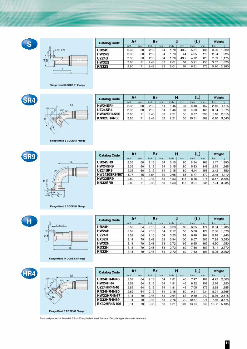
R1.971.972.56
505065
0.990.981.14
252529
4.964.695.94
126119151
2.592.143.90
1,175970
1,770
1 1/2
1 1/2
2
UZ24RHW24RHW32R
Catalog Code Thread Weightinch mm inch mm inch mm lbs g
Standard product — Material: SS or SC equivalent steel, Surface: Zinc plating or chromate treatment
A
A
R
Male British Tapered Pipe Thread(BSPT)
(L)
F2.172.172.76
555570
1.971.972.56
505065
5.315.046.26
135128159
2.862.414.31
1,3001,0951,955
1 1/2
1 1/2
2
UZ24FHW24FHW32F
Catalog Code Thread Weightinch mm inch mm inch mm lbs g
(L)
Female Japanese Industrial PipeThread (JIS) Female 30°Seat
30。
30。
C2.172.172.76
555570
1.971.972.56
505065
5.315.046.26
135128159
2.952.494.44
1,3351,1302,015
1 1/2
1 1/2
2
UZ24CHW24CHW32C
Catalog Code Thread Weightinch mm inch mm inch mm lbs g
(L)
Female British Parallel Pipe Thread Male 30°Seat(BSPOR)
G
(L)
30。
H
G
CR42.172.172.76
555570
2.052.052.72
525269
8.978.74
10.35
228222263
4.133.596.40
1,8701,6302,905
1 1/2
1 1/2
2
UZ24CR4T52HW24CR4N52 HW32CR4N69
Catalog Code Thread Weightinch mm inch mm inch mm lbs g
Female British Parallel Pipe Thread Male 30°Seat(BSPOR)
(L)H(L)
45。
30。
CR92.172.172.76
555570
4.134.065.91
105103150
6.145.638.46
156143215
4.044.197.14
1,8301,9003,240
1 1/2
1 1/2
2
UZ24CR9T105HW24CR9N103 HW32CR920
Catalog Code Thread Weightinch mm inch mm inch mm lbs g
Female British Parallel Pipe Thread Male 30°Seat(BSPOR)
(L)90。
F
H
(L)
(L)
G
(L)
Y
X Y
X
X
HX
Y
Y
YX
YX
X
X
(L)S1.701.731.702.012.01
43.244
43.25151
2.132.132.132.482.48
5454546363
2.362.362.362.802.80
6060607171
5.314.654.925.916.81
135118125150173
3.362.042.593.575.20
1,520925
1,1751,6202,360
UB24SHW24SUZ24SHW32SKN32S
Catalog Code Weightinch mminch mm inch mm inch mm lbs g
A B
B
Flange Head S CODE 61 Flange
SR41.461.462.212.21
37375656
6.186.509.37
10.31
157165238262
2.463.045.106.70
1,1151,3752,3153,040
HW24SR4UZ24SR4HW32SR4N56KN32SR4N56
Catalog Code Weight(L)Hinch mminch mm inch mm inch mm lbs g
A
A
H
3.94~4.45
2.79~
2.92 45。
Flange Head S CODE 61 Flange
(L)
SR93.153.153.152.684.534.53
80808068
115115
6.545.836.146.778.469.21
166148156172215234
4.172.793.422.455.577.24
1,8901,2651,5501,1102,5253,285
UB24SR9HW24SR9UZ24SR9HW2420SR9N67HW32SR9KN32SR9
Catalog Code Weight(L)inch mminch mm inch mm inch mm lbs g
A
(L)
90。
H
3.94~4.45
2.79
~2.
92
A
Flange Head S CODE 61 Flange
(L)H3.232.173.233.942.722.722.72
825582
100696969
6.855.086.468.076.657.367.52
174129164205169187191
3.942.363.187.894.306.115.95
1,7851,0701,4403,5801,9502,7702,700
UB24HHW24H UZ24HEX32HHW32H KD32H KN32H
Catalog Code Weightinch mminch mm inch mm inch mm lbs g
A
Flange Head H CODE 62 Flange
HR41.811.811.813.152.642.764.21
464646806770
107
2.132.132.482.48
54546363
2.132.132.131.542.482.48
545454396363
2.132.132.132.482.482.482.48
54545463636363
2.132.132.132.132.482.482.48
54545454636363
2.362.362.802.80
60607171
2.362.362.361.772.802.80
606060457171
2.522.522.523.113.113.113.11
64646479797979
2.522.522.522.523.113.113.11
64646464797979
7.476.227.059.219.80
10.6713.74
189158179234249271349
4.422.763.655.215.767.66
11.32
2,0001,2501,6552,3652,6153,4755,135
UB24HR4N46HW24HR4 UZ24HR4N46KN24HR4N80HW32HR4N67 KD32HR4N69 EX32HR4N106
Catalog Code Weight(L)inch mminch mm inch mm inch mm lbs g
A
A
H
3.94~4.45
2.79~
2.92 45。
Flange Head S CODE 62 Flange
(L)
Standard product — Material: SS or SC equivalent steel, Surface: Zinc plating or chromate treatment
A B3.
94~
4.45 2.79~2.92
(L)
A B3.
94~
4.4
5
2.79~2.92
(L)
B
B
B
B
H
H
BB
B
41

Standard product — Material: SS or SC equivalent steel, Surface: Zinc plating or chromate treatment
HR93.583.584.725.356.105.35
9191
120136155136
2.132.132.132.482.482.48
545454636363
2.522.522.523.113.113.11
646464797979
5.836.506.898.78
11.389.21
148165
75223289234
3.114.075.176.45
11.638.16
1,4101,8452,3402,9255,2753,700
HW24HR9N91UZ24HR9N91UB24HR9N120HW32HR9 EX32HR9N155KD32HR903
Catalog Code Weight(L)inch mminch mm inch mm inch mm lbs g
A B(L)
90。
H
3.94~4.45
2.79~
2.92
AB
Flange Head S CODE 62 Flange
Y
H
ThreadG1.971.972.56
505065
1 1/2
1 1/2
2
0.980.981.14
252529
4.964.695.94
26119151
2.652.113.73
1,200955
1,690
UZ24G HW24G HW32G
Catalog Code Weightinch mm inch mm inch mm lbs gG
A
Male British Parallel Pipe Thread(BSPP)
30。
(L)
A (L)
K1100100112112
3.943.944.414.41
70708080
2.762.763.153.15
36363636
1.421.421.421.42
152139193210
M16M16M16M16
5.985.477.608.27
0.710.710.710.71
18181818
7.316.81
10.0711.53
3,3103,0904,5705,230
UZ24K140HW24K140HW32K150KN32K150
Catalog Code Weightinch mm inch mm inch mm inch mm inch mm lbs g
JIS B 2291 21MPa(210kgf/cm2)Flange
(L)C
JIS SHBBolt dia.
Bolt dia.Bolt
AB
(L)K100100112112
3.943.944.414.41
70708080
2.762.763.153.15
36363636
1.421.421.421.42
152139193210
M16M16M16M16
5.985.477.608.27
0.710.710.710.71
18181818
7.318.079.74
11.62
3,3103,6604,4205,270
UZ24K40HW24K40 HW32K50 KN32K50
Catalog Code Weightinch mm inch mm inch mm inch mm inch mm lbs g
JIS B 2291 21MPa(210kgf/cm2)Flange
(L)C
2.4
4.1
JIS SHABolt dia.
C Bolt dia.Bolt
AB
Standard product — Material: SS or SC equivalent steel, Surface: Zinc plating or chromate treatment
(L)K29292
100100
3.623.623.943.94
65657373
2.562.562.872.87
36363636
1.421.421.421.42
152139193210
M16M16M16M16
5.985.477.608.27
0.710.710.710.71
18181818
6.697.508.779.99
3,0303,4003,9804,530
UZ24K240HW24K240HW32K250KN32K250
Catalog Code Weightinch mm inch mm inch mm inch mm inch mm lbs g
JIS B 2291 21MPa(210kgf/cm2)Flange
(L)C
2.4
4.1
B A
JIS SSABolt dia.
C Bolt dia.BoltA B
K39292
100100
3.623.623.943.94
65657373
2.562.562.872.87
36363636
1.421.421.421.42
152139193210
5.985.477.608.27
M16M16M16M16
3,0302,8103,9704,610
6.696.198.75
10.16
UZ24K340HW24K340HW32K350KN32K350
Catalog Code Weightinch mm inch mm inch mm inch mm lbs g
JIS B 2291 21MPa(210kgf/cm2)Flange
(L)C
B
JIS SSBBolt [thread] dia.
Bolt
A
Bolt dia.(L)
JIS B 2291 20.5MPa Tube Flange
2.4
4.1
A BC
B
E
(L)
DBolt dia.
K43.623.623.943.94
UZ24K440HW24K440HW32K450KN32K450
Catalog Code Weightinch
9292
100100
mm2.56 2.56 2.87 2.87
inch65657373
mm2.80 2.80 3.35 3.35
inch71718585
mm4.334.33 4.92 4.92
inch110110125125
mm1.81 1.81 1.97 1.97
inch46465050
mm7.09 7.52 9.13 9.80
inch180191232249
M16M16M16M16
mm0.71 0.71 0.71 0.71
inch18181818
mm11.7411.40 17.39 18.69
lbs5,3205,1707,8908,480
gJIS LSA C D E BoltBA
KR9 JIS SHA Bolt dia.
3.94 3.94 4.41 4.41
UZ24K40R915HW24K40R911HW32K50R906KN32K50R907
Catalog Code Weightinch
100100112112
mm2.76 2.76 3.15 3.15
inch70708080
mm1.42 1.42 1.42 1.42
inch36363636
mm5.12 5.12 5.94 5.94
inch130130151151
mm7.60 7.32
10.35 10.83
inch193186263275
M16M16M16M16
mm0.71 0.71 0.71 0.71
inch18181818
mm9.008.77
13.6715.04
inch4,0753,9806,2006,820
gBolt
JIS B 2291 20.5MPa Tube Flange
2.4
4.1
N±3
C
B
(L)
ABolt dia.
90。
A B
(L)CA B
Y
(L)CA B
(L)C NBA
K1R9 JIS SHB Bolt dia.
3.94 4.41 4.41
HW24K140R9N130HW32K150R927KN32K150R916
Catalog Code Weightinch
100112112
mm2.76 3.15 3.15
inch708080
mm1.42 1.42 1.42
inch363636
mm5.12 5.94 5.94
inch130151151
mm7.32
10.35 10.83
inch186263275
M16M16M16
mm0.71 0.71 0.71
inch181818
mm8.64
13.6014.97
inch3,9206,1706,790
gBolt
JIS B 2291 20.5MPa Tube Flange
Bolt dia.
N±3
CB
(L)
A
90。
(L)C NBA
42
Couplings UB / UZ / HW / KN / KD / EX series

Standard product — Material: SS or SC equivalent steel, Surface: Zinc plating or chromate treatment
HR93.583.584.725.356.105.35
9191
120136155136
2.132.132.132.482.482.48
545454636363
2.522.522.523.113.113.11
646464797979
5.836.506.898.78
11.389.21
148165
75223289234
3.114.075.176.45
11.638.16
1,4101,8452,3402,9255,2753,700
HW24HR9N91UZ24HR9N91UB24HR9N120HW32HR9 EX32HR9N155KD32HR903
Catalog Code Weight(L)inch mminch mm inch mm inch mm lbs g
A B(L)
90。
H
3.94~4.45
2.79~
2.92
AB
Flange Head S CODE 62 Flange
Y
H
ThreadG1.971.972.56
505065
1 1/2
1 1/2
2
0.980.981.14
252529
4.964.695.94
26119151
2.652.113.73
1,200955
1,690
UZ24G HW24G HW32G
Catalog Code Weightinch mm inch mm inch mm lbs gG
A
Male British Parallel Pipe Thread(BSPP)
30。
(L)
A (L)
K1100100112112
3.943.944.414.41
70708080
2.762.763.153.15
36363636
1.421.421.421.42
152139193210
M16M16M16M16
5.985.477.608.27
0.710.710.710.71
18181818
7.316.81
10.0711.53
3,3103,0904,5705,230
UZ24K140HW24K140HW32K150KN32K150
Catalog Code Weightinch mm inch mm inch mm inch mm inch mm lbs g
JIS B 2291 21MPa(210kgf/cm2)Flange
(L)C
JIS SHBBolt dia.
Bolt dia.Bolt
AB
(L)K100100112112
3.943.944.414.41
70708080
2.762.763.153.15
36363636
1.421.421.421.42
152139193210
M16M16M16M16
5.985.477.608.27
0.710.710.710.71
18181818
7.318.079.74
11.62
3,3103,6604,4205,270
UZ24K40HW24K40 HW32K50 KN32K50
Catalog Code Weightinch mm inch mm inch mm inch mm inch mm lbs g
JIS B 2291 21MPa(210kgf/cm2)Flange
(L)C
2.4
4.1
JIS SHABolt dia.
C Bolt dia.Bolt
AB
Standard product — Material: SS or SC equivalent steel, Surface: Zinc plating or chromate treatment
(L)K29292
100100
3.623.623.943.94
65657373
2.562.562.872.87
36363636
1.421.421.421.42
152139193210
M16M16M16M16
5.985.477.608.27
0.710.710.710.71
18181818
6.697.508.779.99
3,0303,4003,9804,530
UZ24K240HW24K240HW32K250KN32K250
Catalog Code Weightinch mm inch mm inch mm inch mm inch mm lbs g
JIS B 2291 21MPa(210kgf/cm2)Flange
(L)C
2.4
4.1
B A
JIS SSABolt dia.
C Bolt dia.BoltA B
K39292
100100
3.623.623.943.94
65657373
2.562.562.872.87
36363636
1.421.421.421.42
152139193210
5.985.477.608.27
M16M16M16M16
3,0302,8103,9704,610
6.696.198.75
10.16
UZ24K340HW24K340HW32K350KN32K350
Catalog Code Weightinch mm inch mm inch mm inch mm lbs g
JIS B 2291 21MPa(210kgf/cm2)Flange
(L)C
B
JIS SSBBolt [thread] dia.
Bolt
A
Bolt dia.(L)
JIS B 2291 20.5MPa Tube Flange
2.4
4.1
A BC
B
E
(L)
DBolt dia.
K43.623.623.943.94
UZ24K440HW24K440HW32K450KN32K450
Catalog Code Weightinch
9292
100100
mm2.56 2.56 2.87 2.87
inch65657373
mm2.80 2.80 3.35 3.35
inch71718585
mm4.334.33 4.92 4.92
inch110110125125
mm1.81 1.81 1.97 1.97
inch46465050
mm7.09 7.52 9.13 9.80
inch180191232249
M16M16M16M16
mm0.71 0.71 0.71 0.71
inch18181818
mm11.7411.40 17.39 18.69
lbs5,3205,1707,8908,480
gJIS LSA C D E BoltBA
KR9 JIS SHA Bolt dia.
3.94 3.94 4.41 4.41
UZ24K40R915HW24K40R911HW32K50R906KN32K50R907
Catalog Code Weightinch
100100112112
mm2.76 2.76 3.15 3.15
inch70708080
mm1.42 1.42 1.42 1.42
inch36363636
mm5.12 5.12 5.94 5.94
inch130130151151
mm7.60 7.32
10.35 10.83
inch193186263275
M16M16M16M16
mm0.71 0.71 0.71 0.71
inch18181818
mm9.008.77
13.6715.04
inch4,0753,9806,2006,820
gBolt
JIS B 2291 20.5MPa Tube Flange
2.4
4.1
N±3
C
B
(L)
ABolt dia.
90。
A B
(L)CA B
Y
(L)CA B
(L)C NBA
K1R9 JIS SHB Bolt dia.
3.94 4.41 4.41
HW24K140R9N130HW32K150R927KN32K150R916
Catalog Code Weightinch
100112112
mm2.76 3.15 3.15
inch708080
mm1.42 1.42 1.42
inch363636
mm5.12 5.94 5.94
inch130151151
mm7.32
10.35 10.83
inch186263275
M16M16M16
mm0.71 0.71 0.71
inch181818
mm8.64
13.6014.97
inch3,9206,1706,790
gBolt
JIS B 2291 20.5MPa Tube Flange
Bolt dia.
N±3
C
B
(L)
A
90。
(L)C NBA
43

K2R9 JIS SSA Bolt dia.
3.62 3.62 3.94 3.94
UZ24K240R926HW24K240R913HW32K250R925KN32K250R913
Catalog Code Weightinch
9292
100100
mm2.56 2.56 2.87 2.87
inch65657373
mm1.42 1.42 1.42 1.42
inch36363636
mm5.12 5.12 5.94 5.93
inch130130151
150.5
mm7.60 7.32
10.35 10.79
inch193186263274
M16M16M16M16
mm0.71 0.71 0.71 0.71
inch18181818
mm8.387.56
12.0613.43
inch3,7953,4305,4706,090
gBolt
K3R9 JIS SSB
92100100
3.62 3.94 3.94
657373
2.56 2.87 2.87
363636
1.42 1.42 1.42
130151151
7.3210.3510.83
M16M16M16
5.12 5.94 5.94
186263275
7.8712.7914.18
3,5705,8006,430
HW24K340R9N130HW32K350R9N151KN32K350R9N151
Catalog Code Weightinch mm inch mm inch mm inch mm inch mm lbs g
Bolt
Q22.172.17
5555
2.172.17
5555
5.006.10
127155
2.944.42
1,3352,005
2-122-12
HW24Q2KN24Q2
Catalog Code Thread Weightinch mm inch mm inch mm lbs g
Female O-Ring Face Seal
UNF (L) (L)
JIS B 2291 20.5MPa Tube Flange
2.4
4.1
N±3
C
B
(L)
ABolt dia.
90。
JIS B 2291 20.5MPa Tube Flange
Bolt [thread] dia.
N±3
C
B
(L)
A
90。
Standard product — Material: SS or SC equivalent steel, Surface: Zinc plating or chromate treatment
1.97 50 3.58 91 5.51 140 4.02 1,8252-12HW24Q2R9
Catalog Code Thread Weight(L)Hinch mm inch mm inch mm lbs gQ2R9
Female O-Ring Face Seal
UNF
H
(L)
90。
F22.172.95
5575
2.172.95
5575
5.356.65
136169
2.925.75
1,3252,610
1 5/8 -121 5/8 -12
HW24F2HW32F2
Catalog Code Thread Weight(L)inch mm inch mm inch mm lbs g
(L)
37。
UNF
JIC 37° Female
(L)C NBA
(L)C NBA
X
X
X
Y
YX
X
XY
R0.750.750.750.670.670.750.870.750.750.751.060.870.871.181.181.421.421.972.56
19191917171922191919272222303036365065
0.510.510.510.510.510.590.590.590.590.590.710.710.710.790.790.870.870.981.14
13131313131515151515181818202022222529
1.891.93
2.871.971.972.683.112.282.242.283.542.522.643.352.993.663.394.695.94
4849735050687958575890646785769386
119151
0.100.11
0.230.100.110.240.310.170.200.210.490.290.280.620.560.950.871.983.51
4550
1054550
110140
759095
220130125280255430395900
1,590
1/41/41/41/41/43/83/83/83/83/81/21/21/23/43/411
1 1/2
2
EA0304REC0304REK04RGA04RGB04RKH06REK06RGA06RUF06RUG06REK08RUF08RUG08RGB12RUG12RGB16RUG16REC24REC32R
Catalog Code Thread Weightinch mm inch mm inch mm lbs g
Standard product — Material: SS or SC equivalent steel, Surface: Zinc plating or chromate treatment
A
A
R
Male British Tapered Pipe Thread(BSPT)
(L)
F0.750.750.750.750.870.870.871.061.061.421.421.611.612.172.76
191919192222222727363641415570
0.750.750.670.670.750.750.750.870.871.181.181.421.421.972.56
191917171919192222303036365065
2.092.132.202.202.442.402.522.642.763.583.193.903.625.046.26
53545656626164677091819992
128159
0.130.150.140.140.200.230.240.330.330.780.731.141.062.234.02
6070656590
105110150150355330515480
1,0101,825
1/41/41/41/43/83/83/81/21/23/43/411
1 1/22
EA0304FEC0304FGA04FGB04FGA06FUF06FUG06FUF08FUG08FGB12FUG12FGB16FUG16FEC24FEC32F
Catalog Code Thread Weightinch mm inch mm inch mm lbs g
(L)
Female Japanese Industrial PipeThread (JIS) Female 30°Seat
30。
(L)
Equipped with safety hole
A(L)
GRounded
Q 0.750.871.060.87
19222722
0.39 0.39 0.43 0.39
10101110
3.113.113.43
2.83
79798772
0.270.320.50
0.29
123146227130
1/43/81/23/8
EK04QEK06QEK08QKH06QH22
Catalog Code Thread Weightinch mm inch mm inch mm lbs g
A (L)
G
(L)
X
Y
Y
Y
Y
YX
Y
Y
44
Couplings UB / UZ / HW / KN / KD / EX series

K2R9 JIS SSA Bolt dia.
3.62 3.62 3.94 3.94
UZ24K240R926HW24K240R913HW32K250R925KN32K250R913
Catalog Code Weightinch
9292
100100
mm2.56 2.56 2.87 2.87
inch65657373
mm1.42 1.42 1.42 1.42
inch36363636
mm5.12 5.12 5.94 5.93
inch130130151
150.5
mm7.60 7.32
10.35 10.79
inch193186263274
M16M16M16M16
mm0.71 0.71 0.71 0.71
inch18181818
mm8.387.56
12.0613.43
inch3,7953,4305,4706,090
gBolt
K3R9 JIS SSB
92100100
3.62 3.94 3.94
657373
2.56 2.87 2.87
363636
1.42 1.42 1.42
130151151
7.3210.3510.83
M16M16M16
5.12 5.94 5.94
186263275
7.8712.7914.18
3,5705,8006,430
HW24K340R9N130HW32K350R9N151KN32K350R9N151
Catalog Code Weightinch mm inch mm inch mm inch mm inch mm lbs g
Bolt
Q22.172.17
5555
2.172.17
5555
5.006.10
127155
2.944.42
1,3352,005
2-122-12
HW24Q2KN24Q2
Catalog Code Thread Weightinch mm inch mm inch mm lbs g
Female O-Ring Face Seal
UNF (L) (L)
JIS B 2291 20.5MPa Tube Flange
2.4
4.1
N±3
C
B
(L)
ABolt dia.
90。
JIS B 2291 20.5MPa Tube Flange
Bolt [thread] dia.
N±3
C
B
(L)
A
90。
Standard product — Material: SS or SC equivalent steel, Surface: Zinc plating or chromate treatment
1.97 50 3.58 91 5.51 140 4.02 1,8252-12HW24Q2R9
Catalog Code Thread Weight(L)Hinch mm inch mm inch mm lbs gQ2R9
Female O-Ring Face Seal
UNF
H
(L)
90。
F22.172.95
5575
2.172.95
5575
5.356.65
136169
2.925.75
1,3252,610
1 5/8 -121 5/8 -12
HW24F2HW32F2
Catalog Code Thread Weight(L)inch mm inch mm inch mm lbs g
(L)
37。
UNF
JIC 37° Female
(L)C NBA
(L)C NBA
X
X
X
Y
YX
X
XY
R0.750.750.750.670.670.750.870.750.750.751.060.870.871.181.181.421.421.972.56
19191917171922191919272222303036365065
0.510.510.510.510.510.590.590.590.590.590.710.710.710.790.790.870.870.981.14
13131313131515151515181818202022222529
1.891.93 2.871.971.972.683.112.282.242.283.542.522.643.352.993.663.394.695.94
4849735050687958575890646785769386
119151
0.100.11
0.230.100.110.240.310.170.200.210.490.290.280.620.560.950.871.983.51
4550
1054550
110140
759095
220130125280255430395900
1,590
1/41/41/41/41/43/83/83/83/83/81/21/21/23/43/411
1 1/2
2
EA0304REC0304REK04RGA04RGB04RKH06REK06RGA06RUF06RUG06REK08RUF08RUG08RGB12RUG12RGB16RUG16REC24REC32R
Catalog Code Thread Weightinch mm inch mm inch mm lbs g
Standard product — Material: SS or SC equivalent steel, Surface: Zinc plating or chromate treatment
A
A
R
Male British Tapered Pipe Thread(BSPT)
(L)
F0.750.750.750.750.870.870.871.061.061.421.421.611.612.172.76
191919192222222727363641415570
0.750.750.670.670.750.750.750.870.871.181.181.421.421.972.56
191917171919192222303036365065
2.092.132.202.202.442.402.522.642.763.583.193.903.625.046.26
53545656626164677091819992
128159
0.130.150.140.140.200.230.240.330.330.780.731.141.062.234.02
6070656590
105110150150355330515480
1,0101,825
1/41/41/41/43/83/83/81/21/23/43/411
1 1/22
EA0304FEC0304FGA04FGB04FGA06FUF06FUG06FUF08FUG08FGB12FUG12FGB16FUG16FEC24FEC32F
Catalog Code Thread Weightinch mm inch mm inch mm lbs g
(L)
Female Japanese Industrial PipeThread (JIS) Female 30°Seat
30。
(L)
Equipped with safety hole
A(L)
GRounded
Q 0.750.871.060.87
19222722
0.39 0.39 0.43 0.39
10101110
3.113.113.43 2.83
79798772
0.270.320.50 0.29
123146227130
1/43/81/23/8
EK04QEK06QEK08QKH06QH22
Catalog Code Thread Weightinch mm inch mm inch mm lbs g
A (L)
G
(L)
X
Y
Y
Y
Y
YX
Y
Y
45
EA / EC / EK / GA / GB / UF / UG / KH seriesCouplings

Standard product — Material: SS or SC equivalent steel, Surface: Zinc plating or chromate treatment
Standard product — Material: SS or SC equivalent steel, Surface: Zinc plating or chromate treatment
30。
C0.750.750.750.750.870.870.871.061.061.421.421.611.612.172.76
191919192222222727363641415570
0.750.750.670.670.750.750.750.870.871.181.181.421.421.972.56
191917171919192222303036365065
2.092.132.202.202.442.442.442.642.763.543.193.663.625.046.26
53545656626262677090819392
128159
0.130.150.140.140.200.230.240.340.330.790.741.151.072.284.08
6070656590
105110155150360335520485
1,0351,850
1/41/41/41/43/83/83/81/21/23/43/411
1 1/2
2
EA0304CEC0304CGA04CGB04CGA06CUF06CUG06CUF08CUG08CGB12CUG12CGB16CUG16CEC24CEC32C
Catalog Code Thread Weightinch mm inch mm inch mm lbs g
(L)
Female British Parallel Pipe Thread Male 30°Seat(BSPOR)
G
(L)
30。
H
G
CR40.750.75
1919
0.940.94
2424
3.033.03
7777
0.170.17
7575
1/41/4
GA04CR4GB04CR4
Catalog Code Thread Weightinch mm inch mm inch mm lbs g
Female British Parallel Pipe Thread Male 30°Seat(BSPOR)
(L)H(L)
45。
30。
CR90.750.750.870.870.871.061.061.421.421.612.172.76
191922222227273636415570
0.940.941.501.501.501.811.812.362.362.764.135.91
24243838384646606070
105150
2.362.362.642.642.763.393.504.023.664.657.248.46
60606767708689
10293
118184215
0.150.150.250.290.300.460.450.970.911.493.137.10
7070
115130135210205440415675
1,4203,220
1/41/43/83/83/81/21/23/43/41
1 1/2
2
GA04CR9GB04CR9GA06CR9UF06CR9UG06CR9UF08CR9UG08CR9GB12CR9UG12CR9UG16CR9EC24CR9EC32CR9
Catalog Code Thread Weightinch mm inch mm inch mm lbs g
Female British Parallel Pipe Thread Male 30°Seat(BSPOR)
(L)90。
F
H
(L)
S1.255~1.2501.565~1.5602.125~2.1152.500~2.490
31.88~31.7539.75~39.6253.98~53.7263.50~63.25
1.38 1.38 1.73 1.97
35354450
3.543.664.695.91
9093
119150
0.66 0.96 1.74 3.59
300435790
1,630
GB12SGB16SEC24SEC32S
Catalog Code Weightinch mm
38.1044.4560.3271.42
1.501.752.372.81
inch mm inch mm inch mm lbs g
SR91.255~1.2501.565~1.560
31.88~31.7539.75~39.62
38.1044.45
1.501.75
2.13 2.36
5460
3.94 4.45
100113
0.85 1.27
385575
GB12SR9GB16SR9
Catalog Code Weight(L)inch mminch mm inch mm inch mm lbs g
(L)
90。
H
3.94~4.45
2.79~
2.92
AB
Flange Head S CODE 61 Flange
H1.255~1.2501.565~1.560
1.255~1.2501.565~1.560
31.88~31.7539.75~39.62
1.38 1.50
3538
3.54 3.82
9097
0.69 1.06
315480
GB12HGB16H
Catalog Code Weightinch mm
41.2847.63
1.621.87
1.621.87
inch mm inch mm inch mm lbs g
Flange Head H CODE 62 Flange
HR931.88~31.7539.75~39.62
41.2847.63
2.28 2.87
5873
3.98 4.45
101113
0.90 1.41
410640
GB12HR9GB16HR9
Catalog Code Weightinch mminch mm inch mm inch mm lbs g
ThreadG0.670.670.750.750.871.181.181.42
1717191922303036
1/41/43/83/81/23/43/41
0.510.510.590.590.710.790.790.87
1313151518202022
1.971.972.282.242.522.992.993.66
5050585764767693
0.100.110.150.200.280.610.550.95
45507090
125275250430
GA04GGB04GGA06GUF06GUF08GGB12GUG12GGB16G
Catalog Code Weightinch mm inch mm inch mm lbs g
A (L)
Flange Head S CODE 61 Flange
A B3.
94~
4.45
2.79~2.92
(L)
3.94~
4.45
2.79~2.92
(L)
X
X
HX
Y
Y
X
X
X
A B H
(L)A B
(L)A B H
(L)A B
Y
(L)
90。
H
3.94~4.45
2.79~
2.92
A
Flange Head S CODE 61 Flange
B
G
A
Male British Parallel Pipe Thread(BSPP)
30。
(L)
Y
A B
46
EA / EC / EK / GA / GB / UF / UG / KH seriesCouplings
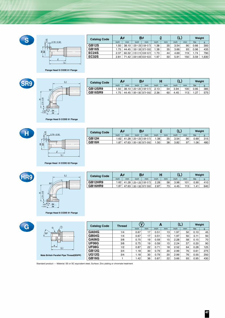
Standard product — Material: SS or SC equivalent steel, Surface: Zinc plating or chromate treatment
Standard product — Material: SS or SC equivalent steel, Surface: Zinc plating or chromate treatment
30。
C0.750.750.750.750.870.870.871.061.061.421.421.611.612.172.76
191919192222222727363641415570
0.750.750.670.670.750.750.750.870.871.181.181.421.421.972.56
191917171919192222303036365065
2.092.132.202.202.442.442.442.642.763.543.193.663.625.046.26
53545656626262677090819392
128159
0.130.150.140.140.200.230.240.340.330.790.741.151.072.284.08
6070656590
105110155150360335520485
1,0351,850
1/41/41/41/43/83/83/81/21/23/43/411
1 1/2
2
EA0304CEC0304CGA04CGB04CGA06CUF06CUG06CUF08CUG08CGB12CUG12CGB16CUG16CEC24CEC32C
Catalog Code Thread Weightinch mm inch mm inch mm lbs g
(L)
Female British Parallel Pipe Thread Male 30°Seat(BSPOR)
G
(L)
30。
H
G
CR40.750.75
1919
0.940.94
2424
3.033.03
7777
0.170.17
7575
1/41/4
GA04CR4GB04CR4
Catalog Code Thread Weightinch mm inch mm inch mm lbs g
Female British Parallel Pipe Thread Male 30°Seat(BSPOR)
(L)H(L)
45。
30。
CR90.750.750.870.870.871.061.061.421.421.612.172.76
191922222227273636415570
0.940.941.501.501.501.811.812.362.362.764.135.91
24243838384646606070
105150
2.362.362.642.642.763.393.504.023.664.657.248.46
60606767708689
10293
118184215
0.150.150.250.290.300.460.450.970.911.493.137.10
7070
115130135210205440415675
1,4203,220
1/41/43/83/83/81/21/23/43/41
1 1/2
2
GA04CR9GB04CR9GA06CR9UF06CR9UG06CR9UF08CR9UG08CR9GB12CR9UG12CR9UG16CR9EC24CR9EC32CR9
Catalog Code Thread Weightinch mm inch mm inch mm lbs g
Female British Parallel Pipe Thread Male 30°Seat(BSPOR)
(L)90。
F
H
(L)
S1.255~1.2501.565~1.5602.125~2.1152.500~2.490
31.88~31.7539.75~39.6253.98~53.7263.50~63.25
1.38 1.38 1.73 1.97
35354450
3.543.664.695.91
9093
119150
0.66 0.96 1.74 3.59
300435790
1,630
GB12SGB16SEC24SEC32S
Catalog Code Weightinch mm
38.1044.4560.3271.42
1.501.752.372.81
inch mm inch mm inch mm lbs g
SR91.255~1.2501.565~1.560
31.88~31.7539.75~39.62
38.1044.45
1.501.75
2.13 2.36
5460
3.94 4.45
100113
0.85 1.27
385575
GB12SR9GB16SR9
Catalog Code Weight(L)inch mminch mm inch mm inch mm lbs g
(L)
90。
H
3.94~4.45
2.79~
2.92
AB
Flange Head S CODE 61 Flange
H1.255~1.2501.565~1.560
1.255~1.2501.565~1.560
31.88~31.7539.75~39.62
1.38 1.50
3538
3.54 3.82
9097
0.69 1.06
315480
GB12HGB16H
Catalog Code Weightinch mm
41.2847.63
1.621.87
1.621.87
inch mm inch mm inch mm lbs g
Flange Head H CODE 62 Flange
HR931.88~31.7539.75~39.62
41.2847.63
2.28 2.87
5873
3.98 4.45
101113
0.90 1.41
410640
GB12HR9GB16HR9
Catalog Code Weightinch mminch mm inch mm inch mm lbs g
ThreadG0.670.670.750.750.871.181.181.42
1717191922303036
1/41/43/83/81/23/43/41
0.510.510.590.590.710.790.790.87
1313151518202022
1.971.972.282.242.522.992.993.66
5050585764767693
0.100.110.150.200.280.610.550.95
45507090
125275250430
GA04GGB04GGA06GUF06GUF08GGB12GUG12GGB16G
Catalog Code Weightinch mm inch mm inch mm lbs g
A (L)
Flange Head S CODE 61 Flange
A B3.
94~
4.45
2.79~2.92
(L)
3.94~
4.45
2.79~2.92
(L)
X
X
HX
Y
Y
X
X
X
A B H
(L)A B
(L)A B H
(L)A B
Y
(L)
90。
H
3.94~4.45
2.79~
2.92
A
Flange Head S CODE 61 Flange
B
G
A
Male British Parallel Pipe Thread(BSPP)
30。
(L)
Y
A B
47

●Compatible FluidMineral Oil
●Inner TubePolyester
●Outer CoverPolyurethane
●Temperature Range: fluid-40℃ to 100℃/ -40°F to 212°F
●Temperature Range : ambient-40℃ to 70℃/ -40°F to 158°F
●Compatible FluidMineral Oil
●Inner TubePolyester
●Outer CoverPolyurethane
●Temperature Range: fluid-40℃ to 100℃/-40°F to 212°F
●Temperature Range : ambient-40℃ to 70℃/-40°F to 158°F
KF・KGI.D.
●Compatible FluidMineral Oil
●Inner TubeNylon 12
●Outer CoverPolyurethane
●Temperature Range: fluid-40℃ to 100℃/-40°F to 212°F
●Temperature Range : ambient-40℃ to 70℃/-40°F to 158°F
KF04KF06KF08KF12 KG06KG08
Catalog Code
1/43/81/23/43/81/2
6.39.5
12.719.5
9.512.7
inch mmO.D.
0.490.650.811.070.680.84
12.516.620.727.317.221.4
inch mm
3,0002,5002,0001,3003,0003,000
20.517.014.0
9.020.520.5
psi MPaMax.W.P.
12,00010,0008,0005,000
12,00012,000
82.068.056.034.582.082.0
psi MPaMin.B.P.
1.381.772.565.122.172.56
354565
1205565
inch mmMin.B.R.
0.070.110.170.220.130.17
110160250330190260
lbs/ft g/mWeight Reinforcement
1P
2P
JY/50
SY/50
SY/50
UX/30
SY/50
Flexible architecture
Small Bending radius
KA/KBI.D.
KA02KA03KA04KA05 KA06 KA08 KA12 KB03KB04KB05KB06KB08KB12 KB16
Catalog Code
1/83/16
1/45/16
3/81/23/4
3/161/4
5/163/81/23/4
1
3.24.86.37.99.5
12.719.0
4.86.37.99.5
12.719.025.4
inch mmO.D.
0.310.370.460.540.610.771.040.410.510.590.670.831.091.41
7.99.4
11.713.715.619.626.310.512.914.916.921.027.835.7
inch mm
2,8002,2002,1001,7001,5001,500
7003,7003,2003,0002,5002,3001,4001,100
19.515.014.512.010.510.5
5.025.522.020.517.016.0
9.57.5
psi MPaMax.W.P.
11,2009,0008,4006,8006,0006,0003,000
15,00012,80012,00010,0009,5005,6004,400
78.061.558.048.042.042.020.5
103.088.082.068.065.538.030.0
psi MPaMin.B.P.
0.471.381.772.362.764.139.061.381.772.362.764.139.06
11.42
1235456070
105230
35456070
105230290
inch mmMin.B.R.
0.030.050.060.070.090.130.190.060.080.090.110.150.230.35
507090
110140190280
90120140170230340520
lbs/ft g/mWeight Reinforcement
1P
2P
1P
SY/50CY/50JY/50
SY/50
CY/50JY/50
SY/50
SY/50CY/50
SY(UL)/50(30)ー
SY(UL)/50
UX/30CY/50
SY(UL)/50(30)ー
SY(UL)/50(30)
UX/30
SPLI.D.
SPL03SPL04SPL06SPL08
Catalog Code
3/161/43/81/2
4.86.39.5
12.7
inch mmO.D.
0.350.420.600.74
9.010.615.218.9
inch mm
2,000
1,500
14.0
10.5
psi MPaMax.W.P.
8,000
6,000
56.0
42.0
psi MPaMin.B.P.
0.791.382.172.76
20355570
inch mmMin.B.R.
0.030.040.080.11
5060
120170
lbs/ft g/mWeight Reinforcement
1P2C
1P
CG/50JG/50
SG/50SG/50
■KB03 to KB12 are equivalent to ISO 3949 type R7 and SAE 100R7 hoses.■KG06 and KG08 are equivalent to SAE 100R18 hoses.
Factory-assembled UNICRIMP-crimpedCompatible coupling/relevant page
Factory-assembled UNICRIMP-crimpedCompatible coupling/relevant page
AG10I.D.
AG1004AG1006AG1008
Catalog Code
1/43/81/2
6.39.5
12.7
inch mmO.D.
0.460.620.78
11.815.719.8
inch mm
10.5
psi MPaMax.W.P.
42.01,500 6,000
psi MPaMin.B.P.
1.382.172.76
355570
inch mmMin.B.R.
0.110.150.24
160230350
lbs/ft g/mWeight Reinforcement
1PJG/48
SG/48 SG/48
Factory-assembled UNICRIMP-crimpedCompatible coupling/relevant page
SFI.D.
SF04SF06SF08SF10
Catalog Code
1/43/81/25/8
6.39.5
12.715.9
inch mmO.D.
0.390.540.650.79
9.913.616.420.1
inch mm
300 2.0
psi MPaMax.W.P.
8,000
6,000
4,000
56.0
42.0
28.0
psi MPaMin.B.P.
2.563.945.326.69
65100135170
inch mmMin.B.R.
0.070.110.140.19
110170210280
lbs/ft g/mWeight Reinforcement
1W(Stainless)
JG/48SG/48
SH/48
SG/48
SH/48-
Factory-assembled UNICRIMP-crimpedCompatible coupling/relevant page
PSI.D.
PS03PS04PS05
Catalog Code
3/161/4
5/16
4.86.37.9
inch mmO.D.
0.390.470.57
10.012.014.6
inch mm
4,5004,0003,600
31.027.524.5
psi MPaMax.W.P.
13,50012,00010,800
93.082.573.5
psi MPaMin.B.P.
1.381.772.36
354560
inch mmMin.B.R.
0.080.110.13
120160200
lbs/ft g/mWeight Reinforcement
1W(Stainless)
Compatible coupling/relevant page
Factory-assembled UNICRIMP-crimpedCompatible coupling/relevant page
If you use a SELFIT FR series coupling with the KF06 hose, the maximum working pressure is 16.0MPa. For details, refer to page 49. Pressurizing the KF06 hose to a working pressure exceeding the maximum could cause it to burst or blow the couplings off. ( In case SELFIT is used) Severe personal injury or death may result if these instructions are not followed.
Warning
One end of an SPL hose can be equipped with a crimped coupling and the other end with a SELFIT coupling. If an SPL hose is equipped with one of the SELFIT FS/FU series couplings, its maximum working pressure will be 10.5MPa, which is different from the pressure specified above. For details, refer to page 54. Pressurizing the SPL hose to a working pressure exceeding the maximum could cause it to burst or blow the couplings off. ( In case SELFIT is used) Severe personal injury or death may result if these instructions are not followed.
Warning
CY/48JY/48SY/48
Factory-assembled
JC70I.D.
JC7003Catalog Code
3/16 4.8inch mm
O.D.
0.51 12.9inch mm
9,900 68.6psi MPaMax.W.P.
20,000 137.2psi MPa
Min.B.P.
2.76 70inch mm
Min.B.R.
0.09 130lbs/ft g/m
Weight Reinforcement
3P
Compatible coupling/relevant page
CW/48Factory-assembled
WSH
JY/48UY/48
JY/48UY/48
Factory-assembled UNICRIMP-crimpedI.D.
WSH04WSH06
Catalog Code
1/43/8
inch mmO.D.
0.500.69
inch mm psi MPaMax.W.P.
psi MPaMin.B.P.
1.38 2.17
inch mmMin.B.R.
0.07 0.11
lbs/ft g/mWeight Reinforcement
1P
Compatible coupling/relevant page
2.0MPa
1Passtage series hose has 30% smaller minimum bending radius than equivalent rubber hose
2Passtage series has 50% lighter weight than equivalent rubber hose.
3The AG10 series for machine tools, the PS/PC series for paint sprays, and the WSH series high pressure washing machines are available.
Small bending radius
Lightweight
Application-specific hoses available
4The SELFIT series, now patented in eight countries including Japan, is a line of push-type coupling systems for high-pressure hoses. They do not require a crimping machine. For details, refer to pages 54 to 58 and the “SELFIT” catalog.
series available for SPL and KF only
Compatible Fluid / Mineral Hydraulic OilInner Tube / PolyurethaneOuter cover / Soft steel wire 1 braid
●●●
Temperature Range: fluid / −40°C to 93°C / −40°F to 199.4°FRecommended Temperature Range: ambient /−40°C to 70°C /
●●
Compatible Fluid / Organic SolventInner Tube / Nylon 12Outer Cover / Soft Vinyl Chloride(PS)
●●●PS For Paint Sprays Temperature Range: fluid / -20℃ to 80℃/ -4°F to 176°F
Temperature Range : ambient / -20℃ to 40℃/ -4°F to 104°F●●
Compatible Fluid / WaterInner Tube / Special resinOuter cover / Polyurethane (red)
●●●
6.39.5
12.817.4 14.0 42.02,000 6,000 35
55100170
WSH For High Pressure Washing Machines
Temperature Range: fluid / 0℃ to 80℃ / −40°F to 199.4°FRecommended Temperature Range: ambient / −40°C to 70°C /
●●
Compatible Fluid / Mineral OilInner Tube / Nylon 12Outer Cover / Polyurethane(Color:Orange)
●●●JC 70 For Hydraulic Jack
Temperature Range: fluid / -40°C to 70°C / -40°F to 158°FTemperature Range : ambient / -40°C to 70°C / -40°F to 158°F
●●
Compatible Fluid / SteamInner Tube / Tetrafluoroethylene
Outer Cover / ‒
●●●SF For Steam
Temperature Range: fluid / 4℃ to 220℃ / -40°F to 158°FTemperature Range : ambient / -40°C to 70°C / -40°F to 158°F
●●
Plastic Hoses For Machine Tools −40°F to 158°F
−40°F to 158°F
■Hoses for hydraulic jacks also include the PrimoLine series hoses, which are available in different sizes than those specified above. (Pages 59 to 63)■JC7003 has excellent electrical insulation properties.
*SF hoses can handle steam as well as fluid. When using them for liquid, contact us for information about the temperature range and working pressure.
Reinforcing
48
PASSTAGE LINE series

●Compatible FluidMineral Oil
●Inner TubePolyester
●Outer CoverPolyurethane
●Temperature Range: fluid-40℃ to 100℃/ -40°F to 212°F
●Temperature Range : ambient-40℃ to 70℃/ -40°F to 158°F
●Compatible FluidMineral Oil
●Inner TubePolyester
●Outer CoverPolyurethane
●Temperature Range: fluid-40℃ to 100℃/-40°F to 212°F
●Temperature Range : ambient-40℃ to 70℃/-40°F to 158°F
KF・KGI.D.
●Compatible FluidMineral Oil
●Inner TubeNylon 12
●Outer CoverPolyurethane
●Temperature Range: fluid-40℃ to 100℃/-40°F to 212°F
●Temperature Range : ambient-40℃ to 70℃/-40°F to 158°F
KF04KF06KF08KF12 KG06KG08
Catalog Code
1/43/81/23/43/81/2
6.39.5
12.719.5
9.512.7
inch mmO.D.
0.490.650.811.070.680.84
12.516.620.727.317.221.4
inch mm
3,0002,5002,0001,3003,0003,000
20.517.014.0
9.020.520.5
psi MPaMax.W.P.
12,00010,0008,0005,000
12,00012,000
82.068.056.034.582.082.0
psi MPaMin.B.P.
1.381.772.565.122.172.56
354565
1205565
inch mmMin.B.R.
0.070.110.170.220.130.17
110160250330190260
lbs/ft g/mWeight Reinforcement
1P
2P
JY/50
SY/50
SY/50
UX/30
SY/50
Flexible architecture
Small Bending radius
KA/KBI.D.
KA02KA03KA04KA05 KA06 KA08 KA12 KB03KB04KB05KB06KB08KB12 KB16
Catalog Code
1/83/16
1/45/16
3/81/23/4
3/161/4
5/163/81/23/4
1
3.24.86.37.99.5
12.719.0
4.86.37.99.5
12.719.025.4
inch mmO.D.
0.310.370.460.540.610.771.040.410.510.590.670.831.091.41
7.99.4
11.713.715.619.626.310.512.914.916.921.027.835.7
inch mm
2,8002,2002,1001,7001,5001,500
7003,7003,2003,0002,5002,3001,4001,100
19.515.014.512.010.510.5
5.025.522.020.517.016.0
9.57.5
psi MPaMax.W.P.
11,2009,0008,4006,8006,0006,0003,000
15,00012,80012,00010,0009,5005,6004,400
78.061.558.048.042.042.020.5
103.088.082.068.065.538.030.0
psi MPaMin.B.P.
0.471.381.772.362.764.139.061.381.772.362.764.139.06
11.42
1235456070
105230
35456070
105230290
inch mmMin.B.R.
0.030.050.060.070.090.130.190.060.080.090.110.150.230.35
507090
110140190280
90120140170230340520
lbs/ft g/mWeight Reinforcement
1P
2P
1P
SY/50CY/50JY/50
SY/50
CY/50JY/50
SY/50
SY/50CY/50
SY(UL)/50(30)ー
SY(UL)/50
UX/30CY/50
SY(UL)/50(30)ー
SY(UL)/50(30)
UX/30
SPLI.D.
SPL03SPL04SPL06SPL08
Catalog Code
3/161/43/81/2
4.86.39.5
12.7
inch mmO.D.
0.350.420.600.74
9.010.615.218.9
inch mm
2,000
1,500
14.0
10.5
psi MPaMax.W.P.
8,000
6,000
56.0
42.0
psi MPaMin.B.P.
0.791.382.172.76
20355570
inch mmMin.B.R.
0.030.040.080.11
5060
120170
lbs/ft g/mWeight Reinforcement
1P2C
1P
CG/50JG/50
SG/50SG/50
■KB03 to KB12 are equivalent to ISO 3949 type R7 and SAE 100R7 hoses.■KG06 and KG08 are equivalent to SAE 100R18 hoses.
Factory-assembled UNICRIMP-crimpedCompatible coupling/relevant page
Factory-assembled UNICRIMP-crimpedCompatible coupling/relevant page
AG10I.D.
AG1004AG1006AG1008
Catalog Code
1/43/81/2
6.39.5
12.7
inch mmO.D.
0.460.620.78
11.815.719.8
inch mm
10.5
psi MPaMax.W.P.
42.01,500 6,000
psi MPaMin.B.P.
1.382.172.76
355570
inch mmMin.B.R.
0.110.150.24
160230350
lbs/ft g/mWeight Reinforcement
1PJG/48
SG/48 SG/48
Factory-assembled UNICRIMP-crimpedCompatible coupling/relevant page
SFI.D.
SF04SF06SF08SF10
Catalog Code
1/43/81/25/8
6.39.5
12.715.9
inch mmO.D.
0.390.540.650.79
9.913.616.420.1
inch mm
300 2.0
psi MPaMax.W.P.
8,000
6,000
4,000
56.0
42.0
28.0
psi MPaMin.B.P.
2.563.945.326.69
65100135170
inch mmMin.B.R.
0.070.110.140.19
110170210280
lbs/ft g/mWeight Reinforcement
1W(Stainless)
JG/48SG/48
SH/48
SG/48
SH/48-
Factory-assembled UNICRIMP-crimpedCompatible coupling/relevant page
PSI.D.
PS03PS04PS05
Catalog Code
3/161/4
5/16
4.86.37.9
inch mmO.D.
0.390.470.57
10.012.014.6
inch mm
4,5004,0003,600
31.027.524.5
psi MPaMax.W.P.
13,50012,00010,800
93.082.573.5
psi MPaMin.B.P.
1.381.772.36
354560
inch mmMin.B.R.
0.080.110.13
120160200
lbs/ft g/mWeight Reinforcement
1W(Stainless)
Compatible coupling/relevant page
Factory-assembled UNICRIMP-crimpedCompatible coupling/relevant page
If you use a SELFIT FR series coupling with the KF06 hose, the maximum working pressure is 16.0MPa. For details, refer to page 49. Pressurizing the KF06 hose to a working pressure exceeding the maximum could cause it to burst or blow the couplings off. ( In case SELFIT is used) Severe personal injury or death may result if these instructions are not followed.
Warning
One end of an SPL hose can be equipped with a crimped coupling and the other end with a SELFIT coupling. If an SPL hose is equipped with one of the SELFIT FS/FU series couplings, its maximum working pressure will be 10.5MPa, which is different from the pressure specified above. For details, refer to page 54. Pressurizing the SPL hose to a working pressure exceeding the maximum could cause it to burst or blow the couplings off. ( In case SELFIT is used) Severe personal injury or death may result if these instructions are not followed.
Warning
CY/48JY/48SY/48
Factory-assembled
JC70I.D.
JC7003Catalog Code
3/16 4.8inch mm
O.D.
0.51 12.9inch mm
9,900 68.6psi MPaMax.W.P.
20,000 137.2psi MPa
Min.B.P.
2.76 70inch mm
Min.B.R.
0.09 130lbs/ft g/m
Weight Reinforcement
3P
Compatible coupling/relevant page
CW/48Factory-assembled
WSH
JY/48UY/48
JY/48UY/48
Factory-assembled UNICRIMP-crimpedI.D.
WSH04WSH06
Catalog Code
1/43/8
inch mmO.D.
0.500.69
inch mm psi MPaMax.W.P.
psi MPaMin.B.P.
1.38 2.17
inch mmMin.B.R.
0.07 0.11
lbs/ft g/mWeight Reinforcement
1P
Compatible coupling/relevant page
2.0MPa
1Passtage series hose has 30% smaller minimum bending radius than equivalent rubber hose
2Passtage series has 50% lighter weight than equivalent rubber hose.
3The AG10 series for machine tools, the PS/PC series for paint sprays, and the WSH series high pressure washing machines are available.
Small bending radius
Lightweight
Application-specific hoses available
4The SELFIT series, now patented in eight countries including Japan, is a line of push-type coupling systems for high-pressure hoses. They do not require a crimping machine. For details, refer to pages 54 to 58 and the “SELFIT” catalog.
series available for SPL and KF only
Compatible Fluid / Mineral Hydraulic OilInner Tube / PolyurethaneOuter cover / Soft steel wire 1 braid
●●●
Temperature Range: fluid / −40°C to 93°C / −40°F to 199.4°FRecommended Temperature Range: ambient /−40°C to 70°C /
●●
Compatible Fluid / Organic SolventInner Tube / Nylon 12Outer Cover / Soft Vinyl Chloride(PS)
●●●PS For Paint Sprays Temperature Range: fluid / -20℃ to 80℃/ -4°F to 176°F
Temperature Range : ambient / -20℃ to 40℃/ -4°F to 104°F●●
Compatible Fluid / WaterInner Tube / Special resinOuter cover / Polyurethane (red)
●●●
6.39.5
12.817.4 14.0 42.02,000 6,000 35
55100170
WSH For High Pressure Washing Machines
Temperature Range: fluid / 0℃ to 80℃ / −40°F to 199.4°FRecommended Temperature Range: ambient / −40°C to 70°C /
●●
Compatible Fluid / Mineral OilInner Tube / Nylon 12Outer Cover / Polyurethane(Color:Orange)
●●●JC 70 For Hydraulic Jack
Temperature Range: fluid / -40°C to 70°C / -40°F to 158°FTemperature Range : ambient / -40°C to 70°C / -40°F to 158°F
●●
Compatible Fluid / SteamInner Tube / Tetrafluoroethylene
Outer Cover / ‒
●●●SF For Steam
Temperature Range: fluid / 4℃ to 220℃ / -40°F to 158°FTemperature Range : ambient / -40°C to 70°C / -40°F to 158°F
●●
Plastic Hoses For Machine Tools −40°F to 158°F
−40°F to 158°F
■Hoses for hydraulic jacks also include the PrimoLine series hoses, which are available in different sizes than those specified above. (Pages 59 to 63)■JC7003 has excellent electrical insulation properties.
*SF hoses can handle steam as well as fluid. When using them for liquid, contact us for information about the temperature range and working pressure.
Special Application Plastic Hoses
49

R0.550.750.870.670.670.670.670.750.750.750.750.870.870.871.261.181.421.42
141722171717171919191922222232303636
0.390.510.590.510.510.510.510.590.590.590.590.710.710.710.790.790.870.87
101315131313131515151518181820202222
1.461.772.361.851.891.851.892.522.402.522.522.872.872.872.832.912.913.50
374560474847486461646473737372747489
0.030.090.110.080.100.090.100.140.150.190.190.250.260.310.360.510.470.82
1540503545404565708585
115120140165230215370
1/81/43/81/41/41/41/43/83/83/83/81/21/21/23/43/411
SY02RCY0304RCW0306RJG04RJY04RSG04RSY04RSY0506R SG06RSY06RUY06RSG08RSH08RSY08RSH1012RSY12R SH1416R SY16R
Catalog Code Thread Weightinch mm inch mm inch mm lbs g
Standard product — Material: SS or SC equivalent steel, Surface: Zinc plating or chromate treatment
A
A
R
Male British Tapered Pipe Thread(BSPT)
(L)
F0.550.750.750.750.750.750.750.870.870.870.871.061.061.061.421.421.611.61
141919191919192222222227272736364141
0.550.750.750.750.750.750.750.870.870.870.751.061.061.061.421.421.611.61
141717171717171719191922222232303636
1.692.091.972.092.132.092.132.362.562.682.682.872.872.993.033.113.153.74
435350535453546065686873737677798095
0.060.100.110.120.130.120.130.170.190.220.220.300.310.350.530.630.640.99
254550556055607585
100100135140160240285290450
1/81/41/41/41/41/41/43/83/83/83/81/21/21/23/43/411
SY02FCG0304FCY0304FJG04FJY04FSG04FSY04FSY0506FSG06FSY06FUY06FSG08FSH08FSY08FSH1012FSY12FSH1416FSY16F
Catalog Code Thread Weightinch mm inch mm inch mm lbs g
(L)
Female Japanese Industrial PipeThread (JIS) Female 30°Seat
30。
C0.550.750.750.750.750.750.750.750.870.870.870.871.061.061.061.421.42
1419191919191919222222222727273641
0.550.750.670.670.670.670.670.670.670.750.750.750.870.870.871.181.42
1417171717171717171919192222223036
1.651.972.091.972.092.132.052.132.322.562.682.682.872.872.993.233.74
4250535053545254596568687373768295
0.060.100.110.110.120.130.120.130.170.200.220.220.310.320.360.650.97
25455050556055607590
100100140145165295440
1/81/41/41/41/41/41/41/43/83/83/83/81/21/21/23/41
SY02CCG0304CCY0304CH17SG0304CJG04CJY04CSG04CSY04CSY0506CSG06CSY06CUY06CSG08CSH08CSY08CSY12CSY16C
Catalog Code Thread Weightinch mm inch mm inch mm lbs g
(L)
Female British Parallel Pipe Thread Male 30°Seat(BSPOR)
G
(L)
C10.750.750.750.87
19191922
0.750.670.670.67
17171717
2.012.132.132.32
51545459
0.110.130.130.17
50606075
1/41/41/43/8
CY0304C1JY04C1SY04C1SY0506C1
Catalog Code Thread Weightinch mm inch mm inch mm lbs g
(L)
Standard product — Material: SS or SC equivalent steel, Surface: Zinc plating or chromate treatment
30。
H
G
CR40.750.750.750.750.870.871.06
19191919222227
0.940.940.940.941.021.020.87
24242424262622
2.722.872.602.604.293.665.16
69736666
10993
131
0.120.140.150.150.250.290.51
55657070
115130230
1/41/41/41/43/83/81/2
CG0304CR4JG04CR4JY04CR4SY04CR4SG06CR4SY06CR4SY08CR4C6
Catalog Code Thread WeightHinch mm inch mm inch mm lbs g
Female British Parallel Pipe Thread Male 30°Seat(BSPOR)
(L)(L)
45。
30。
CR90.750.750.750.750.750.870.871.061.06
191919191922222727
0.940.940.940.940.941.501.501.811.81
242424242438384646
2.052.202.282.202.282.762.874.134.13
52565856587073
105105
0.110.130.140.130.140.250.290.510.44
5060656065
115130230200
1/41/41/41/41/43/83/81/21/2
CG0304CR9JG04CR9JY04CR9SG04CR9SY04CR9SG06CR9SY06CR9SY08CR9C6SG08CR9N46CJ
Catalog Code Thread Weightinch mm inch mm inch mm lbs g
Female British Parallel Pipe Thread Male 30°Seat(BSPOR)
90。
F
H
(L)
Male American Parallel PipeThread Male 30º Seat
(opposing hexagon sides)(opposing hexagon sides)
30°
(L)
NPSM
Y
YX
G30。
(L)
XY
Y
X
X
H (L)X
Y
(L)X Y
X
X
Y
X
X
Y
50
CY / CW / JG / JY / SG / SH / SY / UY seriesCouplings

R0.550.750.870.670.670.670.670.750.750.750.750.870.870.871.261.181.421.42
141722171717171919191922222232303636
0.390.510.590.510.510.510.510.590.590.590.590.710.710.710.790.790.870.87
101315131313131515151518181820202222
1.461.772.361.851.891.851.892.522.402.522.522.872.872.872.832.912.913.50
374560474847486461646473737372747489
0.030.090.110.080.100.090.100.140.150.190.190.250.260.310.360.510.470.82
1540503545404565708585
115120140165230215370
1/81/43/81/41/41/41/43/83/83/83/81/21/21/23/43/411
SY02RCY0304RCW0306RJG04RJY04RSG04RSY04RSY0506R SG06RSY06RUY06RSG08RSH08RSY08RSH1012RSY12R SH1416R SY16R
Catalog Code Thread Weightinch mm inch mm inch mm lbs g
Standard product — Material: SS or SC equivalent steel, Surface: Zinc plating or chromate treatment
A
A
R
Male British Tapered Pipe Thread(BSPT)
(L)
F0.550.750.750.750.750.750.750.870.870.870.871.061.061.061.421.421.611.61
141919191919192222222227272736364141
0.550.750.750.750.750.750.750.870.870.870.751.061.061.061.421.421.611.61
141717171717171719191922222232303636
1.692.091.972.092.132.092.132.362.562.682.682.872.872.993.033.113.153.74
435350535453546065686873737677798095
0.060.100.110.120.130.120.130.170.190.220.220.300.310.350.530.630.640.99
254550556055607585
100100135140160240285290450
1/81/41/41/41/41/41/43/83/83/83/81/21/21/23/43/411
SY02FCG0304FCY0304FJG04FJY04FSG04FSY04FSY0506FSG06FSY06FUY06FSG08FSH08FSY08FSH1012FSY12FSH1416FSY16F
Catalog Code Thread Weightinch mm inch mm inch mm lbs g
(L)
Female Japanese Industrial PipeThread (JIS) Female 30°Seat
30。
C0.550.750.750.750.750.750.750.750.870.870.870.871.061.061.061.421.42
1419191919191919222222222727273641
0.550.750.670.670.670.670.670.670.670.750.750.750.870.870.871.181.42
1417171717171717171919192222223036
1.651.972.091.972.092.132.052.132.322.562.682.682.872.872.993.233.74
4250535053545254596568687373768295
0.060.100.110.110.120.130.120.130.170.200.220.220.310.320.360.650.97
25455050556055607590
100100140145165295440
1/81/41/41/41/41/41/41/43/83/83/83/81/21/21/23/41
SY02CCG0304CCY0304CH17SG0304CJG04CJY04CSG04CSY04CSY0506CSG06CSY06CUY06CSG08CSH08CSY08CSY12CSY16C
Catalog Code Thread Weightinch mm inch mm inch mm lbs g
(L)
Female British Parallel Pipe Thread Male 30°Seat(BSPOR)
G
(L)
C10.750.750.750.87
19191922
0.750.670.670.67
17171717
2.012.132.132.32
51545459
0.110.130.130.17
50606075
1/41/41/43/8
CY0304C1JY04C1SY04C1SY0506C1
Catalog Code Thread Weightinch mm inch mm inch mm lbs g
(L)
Standard product — Material: SS or SC equivalent steel, Surface: Zinc plating or chromate treatment
30。
H
G
CR40.750.750.750.750.870.871.06
19191919222227
0.940.940.940.941.021.020.87
24242424262622
2.722.872.602.604.293.665.16
69736666
10993
131
0.120.140.150.150.250.290.51
55657070
115130230
1/41/41/41/43/83/81/2
CG0304CR4JG04CR4JY04CR4SY04CR4SG06CR4SY06CR4SY08CR4C6
Catalog Code Thread WeightHinch mm inch mm inch mm lbs g
Female British Parallel Pipe Thread Male 30°Seat(BSPOR)
(L)(L)
45。
30。
CR90.750.750.750.750.750.870.871.061.06
191919191922222727
0.940.940.940.940.941.501.501.811.81
242424242438384646
2.052.202.282.202.282.762.874.134.13
52565856587073
105105
0.110.130.140.130.140.250.290.510.44
5060656065
115130230200
1/41/41/41/41/43/83/81/21/2
CG0304CR9JG04CR9JY04CR9SG04CR9SY04CR9SG06CR9SY06CR9SY08CR9C6SG08CR9N46CJ
Catalog Code Thread Weightinch mm inch mm inch mm lbs g
Female British Parallel Pipe Thread Male 30°Seat(BSPOR)
90。
F
H
(L)
Male American Parallel PipeThread Male 30º Seat
(opposing hexagon sides)(opposing hexagon sides)
30°
(L)
NPSM
Y
YX
G30。
(L)
XY
Y
X
X
H (L)X
Y
(L)X Y
X
X
Y
X
X
Y
51

R0.550.670.871.06
14172227
0.550.670.871.06
14172227
1.811.852.282.64
46475867
0.080.110.200.35
355090
160
1/81/43/81/2
FT02RFT04RFT06RFT08R
Catalog Code Thread WeightY1 Y2inch mm inch mm inch mm lbs g
L
R 0.67
0.87 1.06
172227
0.67 0.87 1.06
172227
0.39 0.47 0.51
101213
2.24 2.76 3.15
577080
0.11 0.21 0.40
5095
180
1/43/81/2
FS04RFS06RFS08R
Catalog Code Thread WeightY1 Y2 Cinch mm inch mm inch mm inch mm lbs g
L
F 0.75
0.94 1.18
192430
0.75 0.87 1.06
192227
0.39 0.47 0.51
101213
2.48 2.91 3.23
637482
0.17 0.25 0.45
75115205
1/43/81/2
FU04FFU06FFU08F
Catalog Code Thread WeightY Cinch mm inch mm inch mm inch mm lbs g
L
Applicable hose
Couplings FT series[for only SPL]
Couplings FS・FU series[for only SPL]
R(PT)
Y1(HEX) Y2(DODEC)L Y2
Male British Tapered Pipe Thread(BSPT)
C
R(PT)
Y1(HEX) Y2(DODEC)L Y2
Male British Tapered Pipe Thread(BSPT)
30°R(PT)
G(PF)45°
R(PT)
G( PF )
30°
1/81/43/81/2
3050
100160
0.070.110.220.35
1/81/43/81/2
305080
120
■AdaptersCatalog Code Thread Weight Catalog Code Thread
8021RG02H148021RG048021RG068021RG08
8023RG02H148023RG048023RG068023RG08
glbs0.070.110.180.26
Weight glbs
●Compatible fluid Mineral Oil
●Inner Tube (SPL) Polyester
●Outer Cover (SPL) Polyurethane
●Temperature Range : fluid -30℃ to +80℃ / -22°F to +176°F
●Temperature Range : ambient -30℃ to +70℃ / -22°F to +158°F
Easy piping work in Iimited area
No crimpers required
No external power source required
Repair on-siteFT・FS・FU series●Compatible Fluid Mineral Oil
●Inner Tube (SPL) Polyester
●Outer Cover (SPL) Polyurethane
●Temperature Range : fluid -30℃ to +100℃/ -22°F to +212°F
●Temperature Range : ambient -30℃ to +70℃/ -22°F to +158°F
FR series 1
2
3
4
*3 The SPL02 can withstand a maximum shock pressure of 27.5MPa. For other hoses, do not exceed the maximum working pressure.●The SPL02 and the other hoses have survived impulse testing performed 400,000 times using a flat waveform and a maximum shock pressure of 27.5MPa for SPL02, and under the maximum working pressure for the other hoses.●Be careful when using the FS or FU series of Bridgestone SELFIT couplings.●SPL series cut hoses are also available. They are SPL02/04/06 (20m hose: SPLXX-20, 100m hose: SPLXX-100) and the SPL08 (10m hose: SPL08-10, 50m hose: SPL08-50).●Hoses and fittings cannot be recycled.
Warning
To obtain enough crimping performance, please apply 1MPa or more pressure to selfit at the time of the first use, in case working pressure is below 1MPa.
One end of an SPL hose can be equipped with a crimped coupling and the other end with a SELFIT coupling. The maximum working pressure and the minimum burst pressure for an SPL hose with these couplings are as specified above. Pressurizing this SPL hose to a working pressure exceeding the maximum could cause it to burst or blow the couplings off. Severe personal injury or death may result if these instructions are not followed.
Maximum Working Pressure
10.5-20.5MPa1,500-3,000PSI
SPLI.D.
SPL02SPL04SPL06SPL08
Catalog Code
1/81/43/81/2
3.26.39.5
12.7
inch mmO.D.
0.310.420.600.74
7.910.615.218.9
inch mm
3,000
2,000
1,500
20.5
14.0
10.5
psi MPa psi MPaFT Max.W.P. FS・FU Max.W.P.
−
1,500
−
10.5
psi MPaMin.B.P.
82.0
56.0
42.0
12,000
8,000
6,000
inch mmMin.B.R.
0.471.382.172.76
12355570
0.030.040.080.11
5060
120170
1P2C
1P
lbs/ft g/mWeight Reinforcement
*3
*1 *2
φDL
L
Y3(HEX)G
(PF)
30°
F inch mm inch mm inch mm inch mm inch mm lbs g
WeightD
D
Y1 Y2 Y3Thread
FT02FFT04FFT06FFT08F
Catalog Code
1/81/43/81/2
14−−−
14−−−
14192227
− 192430
−0.750.941.18
52536270
4075
110200
2.052.092.442.85
0.090.170.240.44
0.55−−−
0.55−−−
0.55 0.75 0.87 1.06
Y130°
G(PF) Y3
Y2
Y2
*4<FT02F>
<FT04/06/08F>
G(PF) Y(opposing hexagon sides)
L φDC
30°
Female Japanese Industrial PipeThread (JIS) Female 30°Seat
Female Japanese Industrial PipeThread (JIS) Female 30°Seat
*1 You can use the SPL02 at 100°C / 212°F. If you use couplings FT04, FT06, or FT08 at 100°C / 212°F, the maximum working pressure is 10.5MPa.*2 Note that the figure is different from those for KF series hoses assembled with crimping-type couplings.
Detachable type (before Pressurizing)
L
Caution
Reinforcing
52

R0.550.670.871.06
14172227
0.550.670.871.06
14172227
1.811.852.282.64
46475867
0.080.110.200.35
355090
160
1/81/43/81/2
FT02RFT04RFT06RFT08R
Catalog Code Thread WeightY1 Y2inch mm inch mm inch mm lbs g
L
R 0.67
0.87 1.06
172227
0.67 0.87 1.06
172227
0.39 0.47 0.51
101213
2.24 2.76 3.15
577080
0.11 0.21 0.40
5095
180
1/43/81/2
FS04RFS06RFS08R
Catalog Code Thread WeightY1 Y2 Cinch mm inch mm inch mm inch mm lbs g
L
F 0.75
0.94 1.18
192430
0.75 0.87 1.06
192227
0.39 0.47 0.51
101213
2.48 2.91 3.23
637482
0.17 0.25 0.45
75115205
1/43/81/2
FU04FFU06FFU08F
Catalog Code Thread WeightY Cinch mm inch mm inch mm inch mm lbs g
L
Applicable hose
Couplings FT series[for only SPL]
Couplings FS・FU series[for only SPL]
R(PT)
Y1(HEX) Y2(DODEC)L Y2
Male British Tapered Pipe Thread(BSPT)
C
R(PT)
Y1(HEX) Y2(DODEC)L Y2
Male British Tapered Pipe Thread(BSPT)
30°R(PT)
G(PF)45°
R(PT)
G( PF )
30°
1/81/43/81/2
3050
100160
0.070.110.220.35
1/81/43/81/2
305080
120
■AdaptersCatalog Code Thread Weight Catalog Code Thread
8021RG02H148021RG048021RG068021RG08
8023RG02H148023RG048023RG068023RG08
glbs0.070.110.180.26
Weight glbs
●Compatible fluid Mineral Oil
●Inner Tube (SPL) Polyester
●Outer Cover (SPL) Polyurethane
●Temperature Range : fluid -30℃ to +80℃ / -22°F to +176°F
●Temperature Range : ambient -30℃ to +70℃ / -22°F to +158°F
Easy piping work in Iimited area
No crimpers required
No external power source required
Repair on-siteFT・FS・FU series●Compatible Fluid Mineral Oil
●Inner Tube (SPL) Polyester
●Outer Cover (SPL) Polyurethane
●Temperature Range : fluid -30℃ to +100℃/ -22°F to +212°F
●Temperature Range : ambient -30℃ to +70℃/ -22°F to +158°F
FR series 1
2
3
4
*3 The SPL02 can withstand a maximum shock pressure of 27.5MPa. For other hoses, do not exceed the maximum working pressure.●The SPL02 and the other hoses have survived impulse testing performed 400,000 times using a flat waveform and a maximum shock pressure of 27.5MPa for SPL02, and under the maximum working pressure for the other hoses.●Be careful when using the FS or FU series of Bridgestone SELFIT couplings.●SPL series cut hoses are also available. They are SPL02/04/06 (20m hose: SPLXX-20, 100m hose: SPLXX-100) and the SPL08 (10m hose: SPL08-10, 50m hose: SPL08-50).●Hoses and fittings cannot be recycled.
Warning
To obtain enough crimping performance, please apply 1MPa or more pressure to selfit at the time of the first use, in case working pressure is below 1MPa.
One end of an SPL hose can be equipped with a crimped coupling and the other end with a SELFIT coupling. The maximum working pressure and the minimum burst pressure for an SPL hose with these couplings are as specified above. Pressurizing this SPL hose to a working pressure exceeding the maximum could cause it to burst or blow the couplings off. Severe personal injury or death may result if these instructions are not followed.
Maximum Working Pressure
10.5-20.5MPa1,500-3,000PSI
SPLI.D.
SPL02SPL04SPL06SPL08
Catalog Code
1/81/43/81/2
3.26.39.5
12.7
inch mmO.D.
0.310.420.600.74
7.910.615.218.9
inch mm
3,000
2,000
1,500
20.5
14.0
10.5
psi MPa psi MPaFT Max.W.P. FS・FU Max.W.P.
−
1,500
−
10.5
psi MPaMin.B.P.
82.0
56.0
42.0
12,000
8,000
6,000
inch mmMin.B.R.
0.471.382.172.76
12355570
0.030.040.080.11
5060
120170
1P2C
1P
lbs/ft g/mWeight Reinforcement
*3
*1 *2
φDL
L
Y3(HEX)G
(PF)
30°
F inch mm inch mm inch mm inch mm inch mm lbs g
WeightD
D
Y1 Y2 Y3Thread
FT02FFT04FFT06FFT08F
Catalog Code
1/81/43/81/2
14−−−
14−−−
14192227
− 192430
−0.750.941.18
52536270
4075
110200
2.052.092.442.85
0.090.170.240.44
0.55−−−
0.55−−−
0.55 0.75 0.87 1.06
Y130°
G(PF) Y3
Y2
Y2
*4<FT02F>
<FT04/06/08F>
G(PF) Y(opposing hexagon sides)
L φDC
30°
Female Japanese Industrial PipeThread (JIS) Female 30°Seat
Female Japanese Industrial PipeThread (JIS) Female 30°Seat
*1 You can use the SPL02 at 100°C / 212°F. If you use couplings FT04, FT06, or FT08 at 100°C / 212°F, the maximum working pressure is 10.5MPa.*2 Note that the figure is different from those for KF series hoses assembled with crimping-type couplings.
Detachable type (before Pressurizing)
L
Caution
53

Couplings FR series [for KF]
95130250
95130235
666980475867
21.025.431.821.025.431.8
192227192227
0.210.290.550.210.290.52
0.750.871.060.750.871.06
0.831.001.250.831.001.25
2.602.723.151.852.282.64
956621.0
For F-Type Threads
■AdaptersCatalog Code Thread Weight
R(PT)
G(PF)
30°
8021RG048021RG068021RG08
gibs1/43/81/2
50100160
0.110.220.35
For C-Type Threads For C-Type Threads
1/4 408024RG04 0.09
Catalog Code Thread Weight gibs
For F-Type Threads
30°R(PT)
G(PF)45°
Catalog Code Thread Weight
8023RG048023RG068023RG08
gibs1/43/81/2
5080
120
0.11 0.18 0.26
1/4 608022RG04 0.13
Catalog Code Thread Weight gibs
10º or less
Size
02040608
27263340
−364553
Inserted hose length (mm)
Size
040608
Inserted hose length (mm)
FT series
FR series
FS/FU series
37.540.549
Insertion mark
Insertion markRelease ring
Insertion mark
Removing FS and FU Series Hoses from Couplings
Before it has been pressurized, the hose can be detachable from the coupling.Insert the hose into the coupling, and then, while pressing the release ring onto the coupling by hand, pull the hose back out. If removing the hose is difficult, repeat these steps.
※When you insert the hose into the coupling, the release ring might also be forced in. If so, pull it out by hand.When the insertion mark reaches the release ring, hose insertion is completed.
Use a wrench or socket wrench to screw the couplings into equipment, using the tightening torques listed below.•An impact wrench can also be used for fitting couplings.
The hose is pushed out of this coupling when pressurized.Determine the hose length by considering the displacement.
Size
02R04R06R08R
15253464
R tighteningtorque(N・m) Size F tightening
torque (N・m)
02F04F06F08F
15253464
04R06R08R
253464
R tighteningtorque(N・m)
F tighteningtorque (N・m)Size Size
04F06F08F
253464
FT
concerningFT and FR
FT/ FS
FR
FS・FU
FR
FT series
FS series
FR series
Size
02040608
About 12About 11About 15About 16
−About 11About 15About 16
−20.516.014.0
−About 16About 18About 21
−
10.5
Displacement(mm)due topressure
Pressure(MPa)
Displacement(mm)due topressure
Pressure(MPa)
Displacement(mm)due topressure
Pressure(MPa)
About 11
About 15
About 16
FT series FS/FU series FR series
※Wrap sealing tape around the R thread.
Caution
concerningFS and FU
V notch
White pen
White pen
V notchWhite pen
How to Use FT, FS, FU, and FR Series Couplings
Screwing the Couplings
V notch
φDL
YR(PT) R
R1
φDL
YNPTF
Male British Tapered Pipe Thread(BSPT)
R・R1192227192227
21.025.431.821.025.032.0
717689727590
100135250
95135240
0.750.871.060.750.871.06
0.831.001.250.830.981.26
2.802.993.502.832.953.54
0.220.300.550.210.300.53
1/43/81/2
1/4-183/8-181/2-14
FR04RFR06RFR08RFR04R1FR06R1FR08R1
Catalog Code Thread WeightY1inch mm inch mm inch mm lbs g
LD
φDL
Y
UNF
37°
φDL
Y
G(PF)
F
F2
30°
F・F2 1/4
3/81/2
7/16-209/16-183/4-16
FR04FFR06FFR08FFR04F2FR06F2FR08F2
Catalog Code Thread WeightY1inch mm inch mm inch mm lbs g
LD
19
C
φDL
Y (Opposing hexagon sides)G (PF) type
30°
C0.75 0.83 2.60 0.21 1/4FR04C
Catalog Code Thread WeightY1inch mm inch mm inch mm lbs g
LD
Applicable hose
Maximum Working Pressure
14.5-20.5MPa2,000-3,000PSI
KFI.D. O.D. Max.W.P. Min.B.P. Min.B.R. Weight Reinforcement
KF04KF06KF08
Catalog Code
6.39.5
12.7
mm
1/43/81/2
inch
12.416.620.6
mm
0.490.650.81
inch
20.516.014.0
MPa
3,0002,5002,000
psi
82.062.056.0
12,0009,0008,000
MPapsi
354565
mminch
110160250
1.381.772.56
0.240.350.55
1P
g/mlbs/ft
※ ※
※ Note that the figure is different from those for KF06 hoses assembled with crimping-type couplings.●All KF series hoses have survived impulse testing performed 400,000 times using a flat waveform under the maximum working pressure. ●Hoses and fittings cannot be recycled.
To obtain enough crimping performance, please apply 1MPa or more pressure to selfit at the time of the first use, in case working pressure is below 1MPaOne end of a KF hose can be equipped with a crimped coupling and the other end with a Bridgestone SELFIT coupling. The maximum working pressure and the minimum burst pressure for a KF hose with these couplings are as specified above. Pressurizing the KF hose to a working pressure exceeding the maximum could burst the KF hose or remove the couplings from it. Severe personal injury or death may result if these instructions are not followed.
1
Determining the Hose Length2
Mark the hose with a white pen to ensure it is fully inserted into the coupling. The table below specifies the length from the end of the hose to the mark.
Markings4
Insert the hose into a coupling on the equipment until the hose insertion mark reaches the end of the coupling.Make sure the hose is not extracted after it is inserted.
Inserting a Hose5
Use a hose cutter or a knife to cut the hose perpendicular to its axis.
Cutting the Hose3
(1) R (Male British Tapered Pipe Thread(BSPT)) Type
When the hose is not pressurized, the hose and coupling can rotate freely. To detach the coupling from the equipment, use a wrench to turn the coupling.
Detaching the Couplingfrom Equipment
6
(1) R (Male British Tapered Pipe Thread(BSPT)) Type
For the union nut coupling, use a wrench to turn the nut. This detaches the coupling from the equipment.
(2) R (Female Japanese Industrial Pipe Thread(JIS) Female 30º seat) Type
Union nut couplings can be used for elbow piping.
Tightening torques for the FT, FS, and FU series Tightening torques for the FR series
(2) F (Female Japanese Industrial Pipe Thread(JIS) Female 30º seat) Type
*Unl ike the FT ser ies coupl ings, an impact wrench cannot be used to fit this coupling.
Displacement
Displacement
Cutting the hose at an angle of more than 10º could cause oil leakage or cause come out the couplings from it.
*As the figure to the right shows, the length from the notch on the coupling to the end of the coupling is equal to the inserted hose length.
You cannot detach the hose from the coupling once it is inserted.
You cannot detach the hose from the coupling once it is pressurized.
Warning
Caution
R(PT)
G(PF)
30°
R(PT)
G(PF)
30°
45°
Reinforcing
54
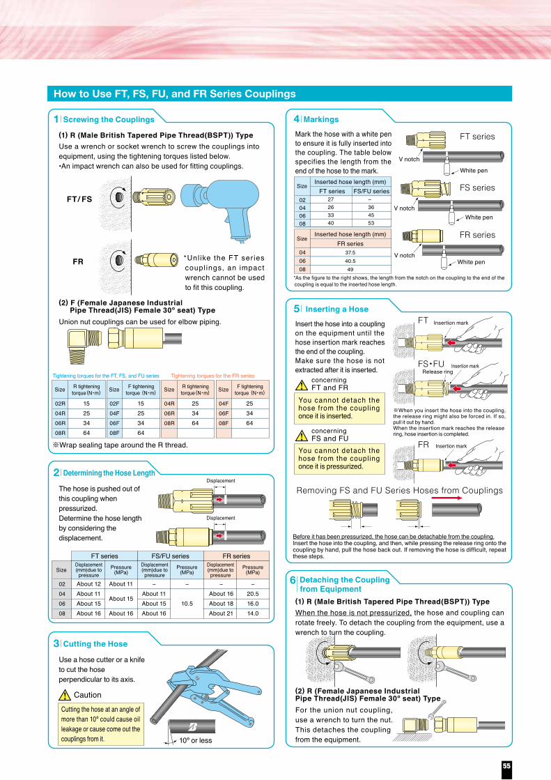
Couplings FR series [for KF]
95130250
95130235
666980475867
21.025.431.821.025.431.8
192227192227
0.210.290.550.210.290.52
0.750.871.060.750.871.06
0.831.001.250.831.001.25
2.602.723.151.852.282.64
956621.0
For F-Type Threads
■AdaptersCatalog Code Thread Weight
R(PT)
G(PF)
30°
8021RG048021RG068021RG08
gibs1/43/81/2
50100160
0.110.220.35
For C-Type Threads For C-Type Threads
1/4 408024RG04 0.09
Catalog Code Thread Weight gibs
For F-Type Threads
30°R(PT)
G(PF)45°
Catalog Code Thread Weight
8023RG048023RG068023RG08
gibs1/43/81/2
5080
120
0.11 0.18 0.26
1/4 608022RG04 0.13
Catalog Code Thread Weight gibs
10º or less
Size
02040608
27263340
−364553
Inserted hose length (mm)
Size
040608
Inserted hose length (mm)
FT series
FR series
FS/FU series
37.540.549
Insertion mark
Insertion markRelease ring
Insertion mark
Removing FS and FU Series Hoses from Couplings
Before it has been pressurized, the hose can be detachable from the coupling.Insert the hose into the coupling, and then, while pressing the release ring onto the coupling by hand, pull the hose back out. If removing the hose is difficult, repeat these steps.
※When you insert the hose into the coupling, the release ring might also be forced in. If so, pull it out by hand.When the insertion mark reaches the release ring, hose insertion is completed.
Use a wrench or socket wrench to screw the couplings into equipment, using the tightening torques listed below.•An impact wrench can also be used for fitting couplings.
The hose is pushed out of this coupling when pressurized.Determine the hose length by considering the displacement.
Size
02R04R06R08R
15253464
R tighteningtorque(N・m) Size F tightening
torque (N・m)
02F04F06F08F
15253464
04R06R08R
253464
R tighteningtorque(N・m)
F tighteningtorque (N・m)Size Size
04F06F08F
253464
FT
concerningFT and FR
FT/ FS
FR
FS・FU
FR
FT series
FS series
FR series
Size
02040608
About 12About 11About 15About 16
−About 11About 15About 16
−20.516.014.0
−About 16About 18About 21
−
10.5
Displacement(mm)due topressure
Pressure(MPa)
Displacement(mm)due topressure
Pressure(MPa)
Displacement(mm)due topressure
Pressure(MPa)
About 11
About 15
About 16
FT series FS/FU series FR series
※Wrap sealing tape around the R thread.
Caution
concerningFS and FU
V notch
White pen
White pen
V notchWhite pen
How to Use FT, FS, FU, and FR Series Couplings
Screwing the Couplings
V notch
φDL
YR(PT) R
R1
φDL
YNPTF
Male British Tapered Pipe Thread(BSPT)
R・R1192227192227
21.025.431.821.025.032.0
717689727590
100135250
95135240
0.750.871.060.750.871.06
0.831.001.250.830.981.26
2.802.993.502.832.953.54
0.220.300.550.210.300.53
1/43/81/2
1/4-183/8-181/2-14
FR04RFR06RFR08RFR04R1FR06R1FR08R1
Catalog Code Thread WeightY1inch mm inch mm inch mm lbs g
LD
φDL
Y
UNF
37°
φDL
Y
G(PF)
F
F2
30°
F・F2 1/4
3/81/2
7/16-209/16-183/4-16
FR04FFR06FFR08FFR04F2FR06F2FR08F2
Catalog Code Thread WeightY1inch mm inch mm inch mm lbs g
LD
19
C
φDL
Y (Opposing hexagon sides)G (PF) type
30°
C0.75 0.83 2.60 0.21 1/4FR04C
Catalog Code Thread WeightY1inch mm inch mm inch mm lbs g
LD
Applicable hose
Maximum Working Pressure
14.5-20.5MPa2,000-3,000PSI
KFI.D. O.D. Max.W.P. Min.B.P. Min.B.R. Weight Reinforcement
KF04KF06KF08
Catalog Code
6.39.5
12.7
mm
1/43/81/2
inch
12.416.620.6
mm
0.490.650.81
inch
20.516.014.0
MPa
3,0002,5002,000
psi
82.062.056.0
12,0009,0008,000
MPapsi
354565
mminch
110160250
1.381.772.56
0.240.350.55
1P
g/mlbs/ft
※ ※
※ Note that the figure is different from those for KF06 hoses assembled with crimping-type couplings.●All KF series hoses have survived impulse testing performed 400,000 times using a flat waveform under the maximum working pressure. ●Hoses and fittings cannot be recycled.
To obtain enough crimping performance, please apply 1MPa or more pressure to selfit at the time of the first use, in case working pressure is below 1MPaOne end of a KF hose can be equipped with a crimped coupling and the other end with a Bridgestone SELFIT coupling. The maximum working pressure and the minimum burst pressure for a KF hose with these couplings are as specified above. Pressurizing the KF hose to a working pressure exceeding the maximum could burst the KF hose or remove the couplings from it. Severe personal injury or death may result if these instructions are not followed.
1
Determining the Hose Length2
Mark the hose with a white pen to ensure it is fully inserted into the coupling. The table below specifies the length from the end of the hose to the mark.
Markings4
Insert the hose into a coupling on the equipment until the hose insertion mark reaches the end of the coupling.Make sure the hose is not extracted after it is inserted.
Inserting a Hose5
Use a hose cutter or a knife to cut the hose perpendicular to its axis.
Cutting the Hose3
(1) R (Male British Tapered Pipe Thread(BSPT)) Type
When the hose is not pressurized, the hose and coupling can rotate freely. To detach the coupling from the equipment, use a wrench to turn the coupling.
Detaching the Couplingfrom Equipment
6
(1) R (Male British Tapered Pipe Thread(BSPT)) Type
For the union nut coupling, use a wrench to turn the nut. This detaches the coupling from the equipment.
(2) R (Female Japanese Industrial Pipe Thread(JIS) Female 30º seat) Type
Union nut couplings can be used for elbow piping.
Tightening torques for the FT, FS, and FU series Tightening torques for the FR series
(2) F (Female Japanese Industrial Pipe Thread(JIS) Female 30º seat) Type
*Unl ike the FT ser ies coupl ings, an impact wrench cannot be used to fit this coupling.
Displacement
Displacement
Cutting the hose at an angle of more than 10º could cause oil leakage or cause come out the couplings from it.
*As the figure to the right shows, the length from the notch on the coupling to the end of the coupling is equal to the inserted hose length.
You cannot detach the hose from the coupling once it is inserted.
You cannot detach the hose from the coupling once it is pressurized.
Warning
Caution
R(PT)
G(PF)
30°
R(PT)
G(PF)
30°
45°
55
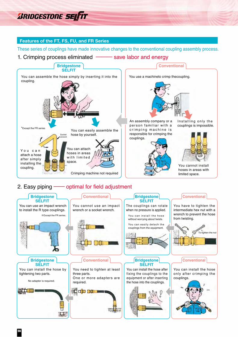
Ultra high pressure hose ●Only Hose Assembly Available
For information about the tightening conditions, refer to page 82.
*108 12 160604
RQ、GG4・C5J4J5
Unit: N・m
300196ーーー
180132ーーー
7088983949
4074ーーー
3037ーーー
*1
*2
*3
08 12 160604RQ、GG4・C5J4J5
Unit: MPa
68.568.5
ーーー
68.588.0
ーーー
68.598.0
294.0245.0294.5
68.5127.5
ーーー
98.0196.0
ーーー
SizeJoint type
SizeJoint type
This hole is basically intended to easily detect small amounts of leakage. Because the liquid dripping from this hole looks like a teardrop, this hole is called a teardrop hole. If actions such as tightening or replacing parts are not taken when a small amount of leakage is detected, the leakage may increase, resulting in liquid ejection. Liquid (water) ejected from the seat may fill joint and the liquid pressure may cause the joint to swell, damaging the joint (threaded part and hex nut). Finally, the joint may detach from the hose. To prevent this problem, the safety hole performs the function of checking for small amounts of leakage. In addition, it allows liquid to escape from the joint, decreasing the pressure and thus preventing the joint (coupling) from detaching from the hose in the case that ejected liquid fills the joint.
*1:The maximum pressure for the ultra high pressure G joint is different from that for the ordinary high-pressure G joint.
*2:Only a 30 hex nut can be used for a C5 joint at 294.0MPa (JAT05). (A 27 hex nut can be used for pressures of 245.0MPa or lower.)
*3:Only a titanium-alloy core can be used for a J4 joint at 294.0MPa (JAT03). For a steel or SUS630 core, a joint rated at 245.0MPa can be used.
1:Use the tightening torques shown in the table on the left when tightening joints. (The torque tolerance for coupling joints is ±10%.)
2:Use these tightening torques when the following conditions coexist: - There is no oil left on either the threaded part or the inside of the nut. - The core hex nut is tightened with a wrench to prevent the coupling from rotating. For information about other tightening torques, contact us.*1:The tightening torque for the R joint varies depending on how its sealing tape
is wrapped. Therefore, the values shown in the table are for reference only.
■Safety Measures<Accessories>
■Maximum Working Pressure for the Joint (Bridgestone PrimoLine)
<Safety Hole in Joint Nut>
■Tightening Torques (for Bridgestone PrimoLine)
Bore Hose Safety chain Safety net
80SAF16CL162
80SAF14CL162
−
80SAF13CL162
−
−
−
−
JAT03
JAM03
JAL03
JAL04
JAK04
JKY04
JAL05
JAK05
03
04
05
8XND10X600Snap hook: 8ZGB6G (sold separately)
The safety nets cannot be installed after hose joint assembly.(They cannot be sold separately.)
Bore Hose Safety chain Safety chainSafety net
80SAF17CL162
−
−
−
−
−
−
−
JAM05
JAL06
JAK06
JAL08
JAK08
JAL10
JAL12
JAL16
05
06
08
10
12
16
8XND13X810Snap hook: 8ZGB8G (sold separately)
The safety nets for 22 hex or smaller nuts can be installed after hose joint assembly. (The safety nets can be sold separately.)
8XND22X1120Snap hook: 8ZGB11G (sold separately)The safety nets for 36 hex or smaller nuts can be installed after hose joint assembly.(The safety nets can be sold separately.)
Safety net
The JAT and JAM series are intended mainly for use with jacks. The unique reinforcing used in their structure makes them flexible. They are lightweight hoses, weighing about half the weight of a conventional hose. With the outer diameter and the bending radius 20% to 30% smaller than those of our other products, these are very easy to use.
The JAT and JAM series are intended for use with water jets—ultra-high pressure hoses—which have been attracting attention recently. The minimum burst pressure is 650MPa for the JAT series and 490 to 588MPa for the JAM series.
The JAL series is intended mainly for use with jacks and high-pressure cleaning tools.They offer high flexibility and working efficiency.
JAT and JAM series
JAL series
JAK and JKY series
You can assemble the hose simply by inserting it into the coupling.
Features of the FT, FS, FU, and FR SeriesThese series of couplings have made innovative changes to the conventional coupling assembly process.1. Crimping process eliminated ─── save labor and energy
BridgestoneSELFIT
Conventional
BridgestoneSELFIT
Conventional BridgestoneSELFIT
Conventional
BridgestoneSELFIT
Conventional BridgestoneSELFIT
Conventional
2. Easy piping ── optimal for field adjustment
*Except the FR series
※Except the FR series.
You use a machineto crimp thecoupling.
Socketwrench
Y o u c a n attach a hose af ter simply installing the coupling.
You can attach hoses in areas w i t h l i m i t e d space.
You can easily assemble the hose by yourself.
Crimping machine not required
An assembly company or a p e r s o n f a m i l i a r w i t h a c r i m p i n g m a c h i n e i s responsible for crimping the couplings.
I n s t a l l i n g o n l y t h e couplings is impossible.
You cannot install hoses in areas with limited space.
You can use an impact wrench to install the R type couplings.
You can install the hose by tightening two parts.
You need to tighten at least three parts.One or more adapters are required.
You can install the hose only af ter c r imping the couplings.
You can install the hose after f ixing the couplings to the equipment or after inserting the hose into the couplings.
You have to t ighten the intermediate hex nut with a wrench to prevent the hose from twisting.
You cannot use an impact wrench or a socket wrench.
The coup l ings can rotate when no pressure is applied.
Yo u c a n i n s t a l l t h e h o s e without worrying about twists.
No adapter is required.
You can eas i l y detach the couplings from the equipment.
To tighten the nut
reference values( )
56

Ultra high pressure hose ●Only Hose Assembly Available
For information about the tightening conditions, refer to page 82.
*108 12 160604
RQ、GG4・C5J4J5
Unit: N・m
300196ーーー
180132ーーー
7088983949
4074ーーー
3037ーーー
*1
*2
*3
08 12 160604RQ、GG4・C5J4J5
Unit: MPa
68.568.5
ーーー
68.588.0
ーーー
68.598.0
294.0245.0294.5
68.5127.5
ーーー
98.0196.0
ーーー
SizeJoint type
SizeJoint type
This hole is basically intended to easily detect small amounts of leakage. Because the liquid dripping from this hole looks like a teardrop, this hole is called a teardrop hole. If actions such as tightening or replacing parts are not taken when a small amount of leakage is detected, the leakage may increase, resulting in liquid ejection. Liquid (water) ejected from the seat may fill joint and the liquid pressure may cause the joint to swell, damaging the joint (threaded part and hex nut). Finally, the joint may detach from the hose. To prevent this problem, the safety hole performs the function of checking for small amounts of leakage. In addition, it allows liquid to escape from the joint, decreasing the pressure and thus preventing the joint (coupling) from detaching from the hose in the case that ejected liquid fills the joint.
*1:The maximum pressure for the ultra high pressure G joint is different from that for the ordinary high-pressure G joint.
*2:Only a 30 hex nut can be used for a C5 joint at 294.0MPa (JAT05). (A 27 hex nut can be used for pressures of 245.0MPa or lower.)
*3:Only a titanium-alloy core can be used for a J4 joint at 294.0MPa (JAT03). For a steel or SUS630 core, a joint rated at 245.0MPa can be used.
1:Use the tightening torques shown in the table on the left when tightening joints. (The torque tolerance for coupling joints is ±10%.)
2:Use these tightening torques when the following conditions coexist: - There is no oil left on either the threaded part or the inside of the nut. - The core hex nut is tightened with a wrench to prevent the coupling from rotating. For information about other tightening torques, contact us.*1:The tightening torque for the R joint varies depending on how its sealing tape
is wrapped. Therefore, the values shown in the table are for reference only.
■Safety Measures<Accessories>
■Maximum Working Pressure for the Joint (Bridgestone PrimoLine)
<Safety Hole in Joint Nut>
■Tightening Torques (for Bridgestone PrimoLine)
Bore Hose Safety chain Safety net
80SAF16CL162
80SAF14CL162
−
80SAF13CL162
−
−
−
−
JAT03
JAM03
JAL03
JAL04
JAK04
JKY04
JAL05
JAK05
03
04
05
8XND10X600Snap hook: 8ZGB6G (sold separately)
The safety nets cannot be installed after hose joint assembly.(They cannot be sold separately.)
Bore Hose Safety chain Safety chainSafety net
80SAF17CL162
−
−
−
−
−
−
−
JAM05
JAL06
JAK06
JAL08
JAK08
JAL10
JAL12
JAL16
05
06
08
10
12
16
8XND13X810Snap hook: 8ZGB8G (sold separately)
The safety nets for 22 hex or smaller nuts can be installed after hose joint assembly. (The safety nets can be sold separately.)
8XND22X1120Snap hook: 8ZGB11G (sold separately)The safety nets for 36 hex or smaller nuts can be installed after hose joint assembly.(The safety nets can be sold separately.)
Safety net
The JAT and JAM series are intended mainly for use with jacks. The unique reinforcing used in their structure makes them flexible. They are lightweight hoses, weighing about half the weight of a conventional hose. With the outer diameter and the bending radius 20% to 30% smaller than those of our other products, these are very easy to use.
The JAT and JAM series are intended for use with water jets—ultra-high pressure hoses—which have been attracting attention recently. The minimum burst pressure is 650MPa for the JAT series and 490 to 588MPa for the JAM series.
The JAL series is intended mainly for use with jacks and high-pressure cleaning tools.They offer high flexibility and working efficiency.
JAT and JAM series
JAL series
JAK and JKY series
You can assemble the hose simply by inserting it into the coupling.
Features of the FT, FS, FU, and FR SeriesThese series of couplings have made innovative changes to the conventional coupling assembly process.1. Crimping process eliminated ─── save labor and energy
BridgestoneSELFIT
Conventional
BridgestoneSELFIT
Conventional BridgestoneSELFIT
Conventional
BridgestoneSELFIT
Conventional BridgestoneSELFIT
Conventional
2. Easy piping ── optimal for field adjustment
*Except the FR series
※Except the FR series.
You use a machineto crimp thecoupling.
Socketwrench
Y o u c a n attach a hose af ter simply installing the coupling.
You can attach hoses in areas w i t h l i m i t e d space.
You can easily assemble the hose by yourself.
Crimping machine not required
An assembly company or a p e r s o n f a m i l i a r w i t h a c r i m p i n g m a c h i n e i s responsible for crimping the couplings.
I n s t a l l i n g o n l y t h e couplings is impossible.
You cannot install hoses in areas with limited space.
You can use an impact wrench to install the R type couplings.
You can install the hose by tightening two parts.
You need to tighten at least three parts.One or more adapters are required.
You can install the hose only af ter c r imping the couplings.
You can install the hose after f ixing the couplings to the equipment or after inserting the hose into the couplings.
You have to t ighten the intermediate hex nut with a wrench to prevent the hose from twisting.
You cannot use an impact wrench or a socket wrench.
The coup l ings can rotate when no pressure is applied.
Yo u c a n i n s t a l l t h e h o s e without worrying about twists.
No adapter is required.
You can eas i l y detach the couplings from the equipment.
To tighten the nut
reference values( )
57
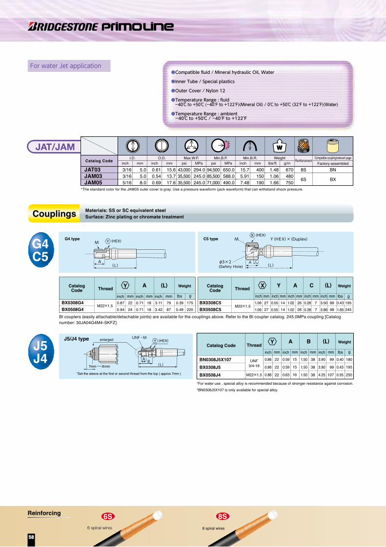
For Hydraulic Jack application
85135 90105135325460540680
68 74 68 69 74105113110119
131813151518202022
192219222227363641
0.750.870.750.870.871.061.421.421.61
0.510.710.510.590.590.710.790.790.87
2.682.912.682.722.914.134.454.334.69
0.190.300.200.230.300.721.011.191.50
G1/4M22×1.5
G1/4R3/8R3/8R1/2G3/4G3/4
G1
BL0304GBL0308G4BL04GBK0506GAK06GAL08RAL1012GAL12GAL16G
A φd
95105125140140330410560700
2.02.02.52.52.53.03.53.53.5
7174737070
102107109112
101010191922252728
191922222227363641
0.750.750.870.870.871.061.421.421.61
0.390.390.390.750.750.870.981.061.10
2.802.912.872.762.764.024.214.294.41
0.220.220.220.260.260.280.350.350.35
0.080.080.100.100.100.120.140.140.14
0.210.230.280.310.310.730.901.231.54
C
5.55.55.56.76.77.09.09.09.0
1/41/43/83/83/81/23/43/41
BL0304QBL04QBK0506QAK06QAL06QAL08QAL1012QAL12QAL16Q
A (L)
GR
φd×2(Safety Hole)
d×2(Safety Hole)
C
BK0506QBL0304Q、BL04Q
A(L)
GR
A(L)
RG/G4
RQ
CatalogCode
CatalogCode
Weight
mminch mminch mminch mminch mminch mminch mminch mminch lbs g lbs g
A(L)
G or M
WeightThread ThreadA (L) (L)
Q typeR typeG/G4 type
●Compatible fluid / Mineral hydraulic Oil, Water
●Inner Tube / Special plastics(JAL03~05), Nylon 12(JAL06~16)
●Outer Cover / Nylon 12
●Temperature Range : fluid -40℃ to +50℃ (-40°F to +122°F)(Mineral Oil) / 0℃ to +50℃ (32°F to +122°F)(Water)
●Temperature Range : ambient -40℃ to +50℃ / -40°F to +122°F
Couplings
5.06.38.09.8
12.816.320.025.0
11.112.615.218.021.025.029.236.0
196.0147.0127.5117.598.088.073.568.5
392.0313.5294.0255.0235.0215.0176.5147.0
57,00045,50042,50037,00034,00031,00025,50021,500
115145165170190210240280
260290380550710
1,0501,1601,510
For water Jet application
J5/J4 type
A B(L)
UNF・Menlarged
*Set the sleeve at the first or second thread from the top ( approx 7mm )
7mm~8mm
180
195
250
99
99
107
15
15
16
38
38
38
22
22
22
0.86
0.86
0.86
0.59
0.59
0.63
1.50
1.50
1.50
3.90
3.90
4.25
0.40
0.43
0.55M22×1.5
3/4-16UNFBN0308J5X107
BX0308J5BX0508J4
*For water use , special alloy is recommended because of stronger resistance against corrosion. *BN0308J5X107 is only available for special alloy.
Catalog CodeJ5J4
mminch mminch mminch mminch lbs g
WeightThread
A B
G4 type
A(L)
MC5 type
A C(L)
Y(HEX)×(Duplex)
φ3×2(Safety Hole)
M
CatalogCode
CatalogCode
175220
7987
2224
0.870.94
0.710.71
1818
3.113.42
0.390.49
M22×1.5BX0308G4BX0508G4
195245
8998
C
M22×1.5BX0308C5BX0508C5
G4C5
mminch mminch mminch mminch mminch mminch mminch mminch lbs g lbs g1.061.06
2727
1414
2626
77
0.550.55
1.021.02
0.280.28
3.503.86
0.431.85
WeightThread Thread Y(L) Weight(L)
(L)
A A
Couplings
JAT/JAMI.D.
JAT03JAM03JAM05
Catalog Code
3/163/165/16
inch mmO.D.
0.610.540.69
inch mm
43,00035,50035,500
psi MPaMax.W.P.
psi MPaMin.B.P.
15.75.917.48
inch mmMin.B.R.
1.481.061.66
5.05.08.0
15.613.717.6
294.0245.0245.0
650.0588.0490.0
94,50085,50071,000
400150190
670480750
lbs/ft g/mWeight Reinforcement
8S
6S
BN
BX
Factory-assembledCompatible coupling/relevant page
JALI.D.
JAL03JAL04JAL05JAL06JAL08JAL10JAL12JAL16
Catalog Code
3/161/4
5/163/81/25/83/4
1
inch mmO.D.
0.440.500.600.710.830.981.151.42
inch mm
28,50021,50018,50017,00014,00013,00010,50010,000
psi MPaMax.W.P.
psi MPaMin.B.P.
4.535.716.506.697.488.279.45
11.02
inch mmMin.B.R.
0.570.640.841.211.572.312.563.33
lbs/ft g/mWeight Reinforcement
4S
BL
BKAK
AL
Factory-assembledCompatible coupling/relevant page
●Compatible fluid / Mineral hydraulic Oil, Water
●Inner Tube / Special plastics
●Outer Cover / Nylon 12
●Temperature Range : fluid -40℃ to +50℃ (-40°F to +122°F)(Mineral Oil) / 0℃ to +50℃ (32°F to +122°F)(Water)
●Temperature Range : ambient -40℃ to +50℃ / -40°F to +122°F
Materials: SS or SC equivalent steelSurface: Zinc plating or chromate treatment
Materials: SS or SC equivalent steelSurface: Zinc plating or chromate treatment
*The standard color for the JAM05 outer cover is gray. Use a pressure waveform (jack waveform) that can withstand shock pressure.
BI couplers (easily attachable/detachable joints) are available for the couplings above. Refer to the BI coupler catalog. 245.0MPa coupling [Catalog number: 30JA04G4M4-SKFZ]
*Use a pressure waveform (jack waveform) that can withstand shock pressure.
Y
Y
Y Y
X
Y (HEX)
Y (HEX)
X (HEX)
Y (HEX) Y (HEX) Y (HEX)Y (HEX)
6 spiral wires
58
Reinforcing

For Hydraulic Jack application
85135 90105135325460540680
68 74 68 69 74105113110119
131813151518202022
192219222227363641
0.750.870.750.870.871.061.421.421.61
0.510.710.510.590.590.710.790.790.87
2.682.912.682.722.914.134.454.334.69
0.190.300.200.230.300.721.011.191.50
G1/4M22×1.5
G1/4R3/8R3/8R1/2G3/4G3/4
G1
BL0304GBL0308G4BL04GBK0506GAK06GAL08RAL1012GAL12GAL16G
A φd
95105125140140330410560700
2.02.02.52.52.53.03.53.53.5
7174737070
102107109112
101010191922252728
191922222227363641
0.750.750.870.870.871.061.421.421.61
0.390.390.390.750.750.870.981.061.10
2.802.912.872.762.764.024.214.294.41
0.220.220.220.260.260.280.350.350.35
0.080.080.100.100.100.120.140.140.14
0.210.230.280.310.310.730.901.231.54
C
5.55.55.56.76.77.09.09.09.0
1/41/43/83/83/81/23/43/41
BL0304QBL04QBK0506QAK06QAL06QAL08QAL1012QAL12QAL16Q
A (L)
GR
φd×2(Safety Hole)
d×2(Safety Hole)
C
BK0506QBL0304Q、BL04Q
A(L)
GR
A(L)
RG/G4
RQ
CatalogCode
CatalogCode
Weight
mminch mminch mminch mminch mminch mminch mminch mminch lbs g lbs g
A(L)
G or M
WeightThread ThreadA (L) (L)
Q typeR typeG/G4 type
●Compatible fluid / Mineral hydraulic Oil, Water
●Inner Tube / Special plastics(JAL03~05), Nylon 12(JAL06~16)
●Outer Cover / Nylon 12
●Temperature Range : fluid -40℃ to +50℃ (-40°F to +122°F)(Mineral Oil) / 0℃ to +50℃ (32°F to +122°F)(Water)
●Temperature Range : ambient -40℃ to +50℃ / -40°F to +122°F
Couplings
5.06.38.09.8
12.816.320.025.0
11.112.615.218.021.025.029.236.0
196.0147.0127.5117.598.088.073.568.5
392.0313.5294.0255.0235.0215.0176.5147.0
57,00045,50042,50037,00034,00031,00025,50021,500
115145165170190210240280
260290380550710
1,0501,1601,510
For water Jet application
J5/J4 type
A B(L)
UNF・Menlarged
*Set the sleeve at the first or second thread from the top ( approx 7mm )
7mm~8mm
180
195
250
99
99
107
15
15
16
38
38
38
22
22
22
0.86
0.86
0.86
0.59
0.59
0.63
1.50
1.50
1.50
3.90
3.90
4.25
0.40
0.43
0.55M22×1.5
3/4-16UNFBN0308J5X107
BX0308J5BX0508J4
*For water use , special alloy is recommended because of stronger resistance against corrosion. *BN0308J5X107 is only available for special alloy.
Catalog CodeJ5J4
mminch mminch mminch mminch lbs g
WeightThread
A B
G4 type
A(L)
MC5 type
A C(L)
Y(HEX)×(Duplex)
φ3×2(Safety Hole)
M
CatalogCode
CatalogCode
175220
7987
2224
0.870.94
0.710.71
1818
3.113.42
0.390.49
M22×1.5BX0308G4BX0508G4
195245
8998
C
M22×1.5BX0308C5BX0508C5
G4C5
mminch mminch mminch mminch mminch mminch mminch mminch lbs g lbs g1.061.06
2727
1414
2626
77
0.550.55
1.021.02
0.280.28
3.503.86
0.431.85
WeightThread Thread Y(L) Weight(L)
(L)
A A
Couplings
JAT/JAMI.D.
JAT03JAM03JAM05
Catalog Code
3/163/165/16
inch mmO.D.
0.610.540.69
inch mm
43,00035,50035,500
psi MPaMax.W.P.
psi MPaMin.B.P.
15.75.917.48
inch mmMin.B.R.
1.481.061.66
5.05.08.0
15.613.717.6
294.0245.0245.0
650.0588.0490.0
94,50085,50071,000
400150190
670480750
lbs/ft g/mWeight Reinforcement
8S
6S
BN
BX
Factory-assembledCompatible coupling/relevant page
JALI.D.
JAL03JAL04JAL05JAL06JAL08JAL10JAL12JAL16
Catalog Code
3/161/4
5/163/81/25/83/4
1
inch mmO.D.
0.440.500.600.710.830.981.151.42
inch mm
28,50021,50018,50017,00014,00013,00010,50010,000
psi MPaMax.W.P.
psi MPaMin.B.P.
4.535.716.506.697.488.279.45
11.02
inch mmMin.B.R.
0.570.640.841.211.572.312.563.33
lbs/ft g/mWeight Reinforcement
4S
BL
BKAK
AL
Factory-assembledCompatible coupling/relevant page
●Compatible fluid / Mineral hydraulic Oil, Water
●Inner Tube / Special plastics
●Outer Cover / Nylon 12
●Temperature Range : fluid -40℃ to +50℃ (-40°F to +122°F)(Mineral Oil) / 0℃ to +50℃ (32°F to +122°F)(Water)
●Temperature Range : ambient -40℃ to +50℃ / -40°F to +122°F
Materials: SS or SC equivalent steelSurface: Zinc plating or chromate treatment
Materials: SS or SC equivalent steelSurface: Zinc plating or chromate treatment
*The standard color for the JAM05 outer cover is gray. Use a pressure waveform (jack waveform) that can withstand shock pressure.
BI couplers (easily attachable/detachable joints) are available for the couplings above. Refer to the BI coupler catalog. 245.0MPa coupling [Catalog number: 30JA04G4M4-SKFZ]
*Use a pressure waveform (jack waveform) that can withstand shock pressure.
Y
Y
Y Y
X
Y (HEX)
Y (HEX)
X (HEX)
Y (HEX) Y (HEX) Y (HEX)Y (HEX)
59

■Connection Method
●Equipment side
●Equipment side BX0308J5BN0308J5X107
BX0308G4BX0508G4
Cone
Adapter
Adapter
Adapter
8083
●Equipment side BX0308C5BX0508C5
BX0308C5BX0508C5
BN0308J5X107BX0308J5
BX0308C5BX0508C5
BN0308J5X107BX0308J5
8084
8081
8082
●Equipment side BX0508J4
8081Use adapter
8084Use adapter for connection
for connection
8082Use adapter for connection
8083Use Cone for connection
3/4-16UNF-2B at both end
18.0
3/4 —16UNF
15.0
30° 12.5S
φ4.
0±0.
1
φ8.
0±0.
1
φ20
.0
C1
—0
+1
2°
18.5
12.0
30° 12.5S
(JA
M05
)φ5.
2±0.
1(J
AM
03)φ
2.0±
0.1
φ11.
0±0.
1
φ23
.0
C1
—0+1.2
°
12.0 φ13
.0
23 .2 18 .051 .2
27HEX
18 . 0 18 . 046 . 0
27HEX
15 . 0 15 . 0
50 . 032HEX
18.0
M22×1.5 — 6H
15.0
30° 12.5S
φ5.
0±0.
1
φ9.
0±0.
1
φ23
.0
C1
—0
+1
2°
To connect J5 type coupling to equipments
To connect G4 type coupling to equipments
1
2
To connect C5 type coupling to equipments3
4
To connect two J5 type couplings
To connect two C5 type couplings
5
To connect J4 type coupling to equipments6
*Same as 2.To con-nect G4 type cou-plings to equip-ments.
G4 and C5 type couplings can be connected directly to each other.
◇BI couplers (easily attachable/detachable joints) are available for BL0304Q and BL04Q. Refer to the BI coupler catalog. 147.0MPa coupling [Catalog number: 30JA04B-SKFZ]
In case of using adapter for Q type conection, please contact us. *8022RG○○ or 8024RG○○ cannot be used.
Couplings
6.36.38.2
10.012.8
12.713.014.117.320.2
68.598.068.568.568.5
166.5245.0176.5156.5147.0
24,00035,50025,50022,50021,500
555580
100130
210310320400540
For Hydraulic Jack application●Compatible fluid / Mineral hydraulic Oil
●Inner Tube / Nylon 12
●Outer Cover / Polyurethane
●Temperature Range : fluid / -40℃ to +80℃(-40°F to +176°F)
●Temperature Range : ambient / -40℃ to +70℃ / -40°F to +158°F
JKY/JAKI.D.
JKY04JAK04JAK05JAK06JAK08
Catalog Code
1/41/4
5/163/81/2
inch mmO.D.
0.500.510.560.680.80
inch mm
10,00014,00010,00010,00010,000
psi MPaMax.W.P.
psi MPaMin.B.P.
2.172.173.153.945.12
inch mmMin.B.R.
0.460.680.710.881.19
lbs/ft g/mWeight Reinforcement
2S+1P
2S+1W
UYAKBK
AK
Factory-assembledCompatible coupling/relevant page
◇BI couplers (easily attachable/detachable joints) for AK04R, AK0406R, BK0506R, AK06R, and AK08R are available. Refer to the BI coupler catalog.
*
Catalog Code 30JCA06C-XXZ30JCA04C-XXZ30JCA08C-XXZ
*Special products
**
68.5MPa couplings
AK04QAK0406QBK0506Q
A(L)
GR
A (L)
GR
C
A
65 75 90110135205
576063727280
151315151518
191922222227
0.750.750.870.870.871.06
0.590.510.590.590.590.71
2.242.362.482.832.833.15
0.140.170.200.240.300.45
3/81/43/83/83/81/2
UY0406RAK04RAK0406RBK0506RAK06RAK08R
90110125140210
0.200.240.280.310.46
——
2.52.53.0
——
0.100.100.12
6667737078
1010191922
2.602.642.872.763.07
1922222227
0.750.870.870.871.06
0.390.390.750.750.87
——
5.56.77.0
——
0.220.260.28
1/43/83/83/81/2
AK04Q*AK0406QBK0506QAK06QAK08Q
φdCCatalogCode Thread Catalog
Code ThreadWeight Weight
RQ
mminch mminch mminch
A(L)
R
lbs g lbs g mminch mminch mminch mminch mminch
A(L) (L)
Q typeR type
*Use a pressure waveform (jack waveform) that can withstand shock pressure.
*Couplings marked with an asterisk are available on request. Use the 30º female seat type adapter by Bridgestone with the Q type coupling.
Materials: SS or SC equivalent steelSurface: Zinc plating or chromate treatment
Prepare the equipment side as shown in the figure on the right.
Prepare the equipment side as shown in the figure on the right.
Prepare the equipment side as shown in the figure on the right.
Prepare the equipment side as shown in the figure on the right.
Y Y
Y (HEX)
Y (HEX) Y (HEX)
60
Reinforcing
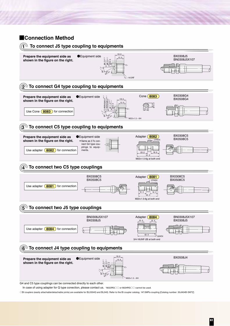
■Connection Method
●Equipment side
●Equipment side BX0308J5BN0308J5X107
BX0308G4BX0508G4
Cone
Adapter
Adapter
Adapter
8083
●Equipment side BX0308C5BX0508C5
BX0308C5BX0508C5
BN0308J5X107BX0308J5
BX0308C5BX0508C5
BN0308J5X107BX0308J5
8084
8081
8082
●Equipment side BX0508J4
8081Use adapter
8084Use adapter for connection
for connection
8082Use adapter for connection
8083Use Cone for connection
3/4-16UNF-2B at both end
18.0
3/4 —16UNF
15.0
30° 12.5S
φ4.
0±0.
1
φ8.
0±0.
1
φ20
.0
C1
—0
+1
2°18.5
12.030
° 12.5S
(JA
M05
)φ5.
2±0.
1(J
AM
03)φ
2.0±
0.1
φ11.
0±0.
1
φ23
.0
C1
—0+1.2
°
12.0 φ13
.023 .2 18 .0
51 .2
27HEX
18 . 0 18 . 046 . 0
27HEX
15 . 0 15 . 0
50 . 032HEX
18.0
M22×1.5 — 6H
15.0
30° 12.5S
φ5.
0±0.
1
φ9.
0±0.
1
φ23
.0
C1
—0
+1
2°
To connect J5 type coupling to equipments
To connect G4 type coupling to equipments
1
2
To connect C5 type coupling to equipments3
4
To connect two J5 type couplings
To connect two C5 type couplings
5
To connect J4 type coupling to equipments6
*Same as 2.To con-nect G4 type cou-plings to equip-ments.
G4 and C5 type couplings can be connected directly to each other.
◇BI couplers (easily attachable/detachable joints) are available for BL0304Q and BL04Q. Refer to the BI coupler catalog. 147.0MPa coupling [Catalog number: 30JA04B-SKFZ]
In case of using adapter for Q type conection, please contact us. *8022RG○○ or 8024RG○○ cannot be used.
Couplings
6.36.38.2
10.012.8
12.713.014.117.320.2
68.598.068.568.568.5
166.5245.0176.5156.5147.0
24,00035,50025,50022,50021,500
555580
100130
210310320400540
For Hydraulic Jack application●Compatible fluid / Mineral hydraulic Oil
●Inner Tube / Nylon 12
●Outer Cover / Polyurethane
●Temperature Range : fluid / -40℃ to +80℃(-40°F to +176°F)
●Temperature Range : ambient / -40℃ to +70℃ / -40°F to +158°F
JKY/JAKI.D.
JKY04JAK04JAK05JAK06JAK08
Catalog Code
1/41/4
5/163/81/2
inch mmO.D.
0.500.510.560.680.80
inch mm
10,00014,00010,00010,00010,000
psi MPaMax.W.P.
psi MPaMin.B.P.
2.172.173.153.945.12
inch mmMin.B.R.
0.460.680.710.881.19
lbs/ft g/mWeight Reinforcement
2S+1P
2S+1W
UYAKBK
AK
Factory-assembledCompatible coupling/relevant page
◇BI couplers (easily attachable/detachable joints) for AK04R, AK0406R, BK0506R, AK06R, and AK08R are available. Refer to the BI coupler catalog.
*
Catalog Code 30JCA06C-XXZ30JCA04C-XXZ30JCA08C-XXZ
*Special products
**
68.5MPa couplings
AK04QAK0406QBK0506Q
A(L)
GR
A (L)
GR
C
A
65 75 90110135205
576063727280
151315151518
191922222227
0.750.750.870.870.871.06
0.590.510.590.590.590.71
2.242.362.482.832.833.15
0.140.170.200.240.300.45
3/81/43/83/83/81/2
UY0406RAK04RAK0406RBK0506RAK06RAK08R
90110125140210
0.200.240.280.310.46
——
2.52.53.0
——
0.100.100.12
6667737078
1010191922
2.602.642.872.763.07
1922222227
0.750.870.870.871.06
0.390.390.750.750.87
——
5.56.77.0
——
0.220.260.28
1/43/83/83/81/2
AK04Q*AK0406QBK0506QAK06QAK08Q
φdCCatalogCode Thread Catalog
Code ThreadWeight Weight
RQ
mminch mminch mminch
A(L)
R
lbs g lbs g mminch mminch mminch mminch mminch
A(L) (L)
Q typeR type
*Use a pressure waveform (jack waveform) that can withstand shock pressure.
*Couplings marked with an asterisk are available on request. Use the 30º female seat type adapter by Bridgestone with the Q type coupling.
Materials: SS or SC equivalent steelSurface: Zinc plating or chromate treatment
Prepare the equipment side as shown in the figure on the right.
Prepare the equipment side as shown in the figure on the right.
Prepare the equipment side as shown in the figure on the right.
Prepare the equipment side as shown in the figure on the right.
Y Y
Y (HEX)
Y (HEX) Y (HEX)
61

30。
GRc
Y(6角対辺)L
E
E30。
GRc
Y(6角対辺)
L
A
E
EBG
R
AC
X
X30°
X
X
G
EB
CA
R
30°
E
G
X
30°
45°
EB
CA
R
X
E
E
45°
30°
EBG
C
A
R
X
X
1922273641505570
35384350566266
71.8
34.534.534.527.520.517.010.510.5
6070
110250290420490965
+04G+06G+08G+12G+16G+20G+24G+32G
2528313740444550
1/43/81/23/41
1 1 2
8007RG048007RG068007RG088007RG128007RG168007RG208007RG248007RG32
8007RG X・Ymm
L mm
/41
/21
1922273641505570
2934404550555764
1315182022252529
4050
100180230350410680
+04C+06C+08C+12C+16C+20C+24C+32C
2125293237383943
1/43/81/23/41
1 1 2
8008RG048008RG068008RG088008RG128008RG168008RG208008RG248008RG32
8008RG Ymm
L mm
Amm
Emm
Emm
/41
/21
141719243036465065
222630364350586375
212528323741505263
101112151719222226
3050
100160250410730920
1,810
+02F+04F+06F+08F+12F+16F+20F+24F+32F
121316172125303438
1/81/43/81/23/41
1 1 2
8021RG02H148021RG048021RG068021RG08
8021RG12 8021RG16 8021RG20 8021RG24 8021RG32
8021RG Xmm
Cmm
Emm
Amm
141618202224272730
Bmm
/41
/21
1719243036465065
2630364350586375
2225303540485062
1112151719222226
6090
150260390740900
1,580
+04C+06C+08C+12C+16C+20C+24C+32C
1316192227303240
1/43/81/23/41
1 1 2
8022RG04 8022RG06 8022RG08 8022RG12 8022RG16 8022RG20 8022RG24 8022RG32
8022RG Xmm
Cmm
Emm
Amm
1315182022252529
Bmm
/41
/21
141719243036465065
181922263034404150
212225283236424351
101113151719222226
205080
120190300530590
1,090
+02F+04F+06F+08F+12F+16F+20F+24F+32F
242529323541515261
1/81/43/81/23/41
1 1 2
8023RG02H14 8023RG04 8023RG06 8023RG08 8023RG12 8023RG16 8023RG20 8023RG24 8023RG32
8023RG Xmm
Cmm
Emm
Amm
141618202224272730
Bmm
/41
/21
1719243036465065
1922263034404150
1922263034404150
1113151719222226
4070
120200300570650
1,200
+04C+06C+08C+12C+16C+20C+24C+32C
2528343742555565
1/43/81/23/41
1 1 2
8024RG04 8024RG06 8024RG08 8024RG12 8024RG16 8024RG20 8024RG24 8024RG32
8024RG Xmm
Cmm
Emm
Amm
1315182022252529
Bmm
/41
/21
30。
GRc
YL
30。
GRc
Y
L
A
EBG
R
AC
X
X30°
X
X
G
EB
CA
R
30°
G
X
30°
45°
EB
CA
R
X
45°
30°
EBG
C
A
R
X
X
E
E
E
E
E
E
Catalog Code
Catalog Code
Catalog Code
Catalog Code
Catalog Code
Catalog Code
Thread
Thread
Thread
Thread
Thread
Thread
Max.W.P Adapter + Coupling
Adapter + Coupling
Adapter + Coupling
Adapter + Coupling
Adapter + Coupling
Adapter + Coupling
Weightg
Weightg
Weightg
Weightg
Weightg
Weightg
Emm
Emm
Emm
Emm
Standard product — Material: SS or SC equivalent steel, Surface: Zinc plating or chromate treatment
E
E
E
30。
GR
Y(6角対辺)
L
A B
30。
GRY(6角対辺)
LA B
GG
30。30。
Y(6角対辺)
L
A B
GRc
30。
Y(6角対辺) A
L
E
30。
G
R
Y(6角対辺)A
L
E
14192227364150557090
32374148545866697685
10131518202225252932
14161820222327293034
204060
100170240420480720
1,300
+02F+04F+06F+08F+12F+16F+20F+24F+32F+40F
23262933384246495256
1/81/43/81/23/41
1 1 2
2
8001RG02 8001RG04* 8001RG06* 8001RG08* 8001RG12 8001RG16 8001RG20 8001RG24 8001RG32 8001RG40
8001RG Ymm
L mm
Amm
Bmm
Emm
8002RG Ymm
L mm
Amm
Bmm
8004GG Ymm
L mm
Amm
Bmm
8005RG Ymm
L mm
Amm
8006RG Ymm
L mm
Amm
/41
/21
/21
1922273641505570
3438465257646575
1315182022252529
1315182022252529
4060
100170240410470760
+04C+06C+08C+12C+16C+20C+24C+32C
2629353944474754
1/43/81/23/41
1 1 2
8002RG048002RG068002RG088002RG128002RG168002RG208002RG248002RG32
/41
/21
1922273641505570
3438465257646575
1315182022252529
1315182022252529
4060
100170240410470760
+04C+06C+08C+12C+16C+20C+24C+32C
2629353944474754
1/43/81/23/41
1 1 2
8004GG048004GG068004GG088004GG128004GG168004GG208004GG248004GG32
/41
/21
1922273641505570
3237424751576165
1618202223272930
406090
180240330400690
+04F+06F+08F+12F+16F+20F+24F+32F
2125273135374141
1/43/81/23/41
1 1 2
8005RG048005RG068005RG088005RG128005RG168005RG208005RG248005RG32
/41
/21
1922273641505570
40424957637174
82.8
1315182022252529
34.534.534.527.520.517.010.510.5
6080
130250330500580
1,040
+04G+06G+08G+12G+16G+20G+24G+32G
3032374447535361
1/43/81/23/41
1 1 2
8006RG048006RG068006RG088006RG128006RG168006RG208006RG248006RG32
/41
/21
30。
GR
Y
L
A B
30。
GRY
LA B
GG
30。30。
Y
L
A B
GRc
30。
Y A
L
30。
G
R
YA
L
E
E
E
E
E
Catalog Code Thread
Thread
Thread
Thread
Thread Max.W.P
Adapter + Coupling
Catalog Code Adapter + Coupling
Catalog Code Adapter + Coupling
Catalog Code Adapter + Coupling
Catalog Code
SIZEMax.W.P.
Adapter + Coupling
Emm
Emm
Emm
Emm
Weightg
Weightg
Weightg
Weightg
Weightg
■When using an adapter, take into account the outline dimensions of the assembled adapter below when determining the length of the assembly hose. (For the L dimensions, refer to page 5.)
*Brass versions are available for the products marked with an asterisk. For their dimensions, refer to the adapter specifications for the ACT series on page 22.
Standard product — Material: SS or SC equivalent steel, Surface: Zinc plating or chromate treatment
04 0634.5
08 1227.5 20.5 17.0 10.5
16 20 24 32MPa
62
Adapters

30。
GRc
Y(6角対辺)L
E
E30。
GRc
Y(6角対辺)
L
A
E
EBG
R
AC
X
X30°
X
X
G
EB
CA
R
30°
E
G
X
30°
45°
EB
CA
R
X
E
E
45°
30°
EBG
C
A
R
X
X
1922273641505570
35384350566266
71.8
34.534.534.527.520.517.010.510.5
6070
110250290420490965
+04G+06G+08G+12G+16G+20G+24G+32G
2528313740444550
1/43/81/23/41
1 1 2
8007RG048007RG068007RG088007RG128007RG168007RG208007RG248007RG32
8007RG X・Ymm
L mm
/41
/21
1922273641505570
2934404550555764
1315182022252529
4050
100180230350410680
+04C+06C+08C+12C+16C+20C+24C+32C
2125293237383943
1/43/81/23/41
1 1 2
8008RG048008RG068008RG088008RG128008RG168008RG208008RG248008RG32
8008RG Ymm
L mm
Amm
Emm
Emm
/41
/21
141719243036465065
222630364350586375
212528323741505263
101112151719222226
3050
100160250410730920
1,810
+02F+04F+06F+08F+12F+16F+20F+24F+32F
121316172125303438
1/81/43/81/23/41
1 1 2
8021RG02H148021RG048021RG068021RG08
8021RG12 8021RG16 8021RG20 8021RG24 8021RG32
8021RG Xmm
Cmm
Emm
Amm
141618202224272730
Bmm
/41
/21
1719243036465065
2630364350586375
2225303540485062
1112151719222226
6090
150260390740900
1,580
+04C+06C+08C+12C+16C+20C+24C+32C
1316192227303240
1/43/81/23/41
1 1 2
8022RG04 8022RG06 8022RG08 8022RG12 8022RG16 8022RG20 8022RG24 8022RG32
8022RG Xmm
Cmm
Emm
Amm
1315182022252529
Bmm
/41
/21
141719243036465065
181922263034404150
212225283236424351
101113151719222226
205080
120190300530590
1,090
+02F+04F+06F+08F+12F+16F+20F+24F+32F
242529323541515261
1/81/43/81/23/41
1 1 2
8023RG02H14 8023RG04 8023RG06 8023RG08 8023RG12 8023RG16 8023RG20 8023RG24 8023RG32
8023RG Xmm
Cmm
Emm
Amm
141618202224272730
Bmm
/41
/21
1719243036465065
1922263034404150
1922263034404150
1113151719222226
4070
120200300570650
1,200
+04C+06C+08C+12C+16C+20C+24C+32C
2528343742555565
1/43/81/23/41
1 1 2
8024RG04 8024RG06 8024RG08 8024RG12 8024RG16 8024RG20 8024RG24 8024RG32
8024RG Xmm
Cmm
Emm
Amm
1315182022252529
Bmm
/41
/21
30。
GRc
YL
30。
GRc
Y
L
A
EBG
R
AC
X
X30°
X
X
G
EB
CA
R
30°
G
X
30°
45°
EB
CA
R
X
45°
30°
EBG
C
A
R
X
X
E
E
E
E
E
E
Catalog Code
Catalog Code
Catalog Code
Catalog Code
Catalog Code
Catalog Code
Thread
Thread
Thread
Thread
Thread
Thread
Max.W.P Adapter + Coupling
Adapter + Coupling
Adapter + Coupling
Adapter + Coupling
Adapter + Coupling
Adapter + Coupling
Weightg
Weightg
Weightg
Weightg
Weightg
Weightg
Emm
Emm
Emm
Emm
Standard product — Material: SS or SC equivalent steel, Surface: Zinc plating or chromate treatment
E
E
E
30。
GR
Y(6角対辺)
L
A B
30。
GRY(6角対辺)
LA B
GG
30。30。
Y(6角対辺)
L
A B
GRc
30。
Y(6角対辺) A
L
E
30。
G
R
Y(6角対辺)A
L
E
14192227364150557090
32374148545866697685
10131518202225252932
14161820222327293034
204060
100170240420480720
1,300
+02F+04F+06F+08F+12F+16F+20F+24F+32F+40F
23262933384246495256
1/81/43/81/23/41
1 1 2
2
8001RG02 8001RG04* 8001RG06* 8001RG08* 8001RG12 8001RG16 8001RG20 8001RG24 8001RG32 8001RG40
8001RG Ymm
L mm
Amm
Bmm
Emm
8002RG Ymm
L mm
Amm
Bmm
8004GG Ymm
L mm
Amm
Bmm
8005RG Ymm
L mm
Amm
8006RG Ymm
L mm
Amm
/41
/21
/21
1922273641505570
3438465257646575
1315182022252529
1315182022252529
4060
100170240410470760
+04C+06C+08C+12C+16C+20C+24C+32C
2629353944474754
1/43/81/23/41
1 1 2
8002RG048002RG068002RG088002RG128002RG168002RG208002RG248002RG32
/41
/21
1922273641505570
3438465257646575
1315182022252529
1315182022252529
4060
100170240410470760
+04C+06C+08C+12C+16C+20C+24C+32C
2629353944474754
1/43/81/23/41
1 1 2
8004GG048004GG068004GG088004GG128004GG168004GG208004GG248004GG32
/41
/21
1922273641505570
3237424751576165
1618202223272930
406090
180240330400690
+04F+06F+08F+12F+16F+20F+24F+32F
2125273135374141
1/43/81/23/41
1 1 2
8005RG048005RG068005RG088005RG128005RG168005RG208005RG248005RG32
/41
/21
1922273641505570
40424957637174
82.8
1315182022252529
34.534.534.527.520.517.010.510.5
6080
130250330500580
1,040
+04G+06G+08G+12G+16G+20G+24G+32G
3032374447535361
1/43/81/23/41
1 1 2
8006RG048006RG068006RG088006RG128006RG168006RG208006RG248006RG32
/41
/21
30。
GR
Y
L
A B
30。
GRY
LA B
GG
30。30。
Y
L
A B
GRc
30。
Y A
L
30。
G
R
YA
L
E
E
E
E
E
Catalog Code Thread
Thread
Thread
Thread
Thread Max.W.P
Adapter + Coupling
Catalog Code Adapter + Coupling
Catalog Code Adapter + Coupling
Catalog Code Adapter + Coupling
Catalog Code
SIZEMax.W.P.
Adapter + Coupling
Emm
Emm
Emm
Emm
Weightg
Weightg
Weightg
Weightg
Weightg
■When using an adapter, take into account the outline dimensions of the assembled adapter below when determining the length of the assembly hose. (For the L dimensions, refer to page 5.)
*Brass versions are available for the products marked with an asterisk. For their dimensions, refer to the adapter specifications for the ACT series on page 22.
Standard product — Material: SS or SC equivalent steel, Surface: Zinc plating or chromate treatment
04 0634.5
08 1227.5 20.5 17.0 10.5
16 20 24 32MPa
63

Flange for JIS 21 MPa
18.64±0.15 3.53±0.1 2108YG08S 08S08H
24.99±0.15 〃 2148YG12S 12S、12SM1012H、12HM10
32.92±0.15 〃 2198YG16S 16S、16SM1016H、16HM12
37.69±0.15 〃 2228YG20S 20S、20SM1220H、20HM12
47.22±0.25 〃 2258YG24S 24S、24SM1224H、24HM14
56.74±0.25 〃 2288YG32S 32S、32SM1232H、32HM20
O-ring for Split Flanges
178YAK15
8YGK15
88YBK215
MY(mm)
26M10×1.5
Smm
10
Dmm
7
Hmm
6032 50
mmK15、K115K20、K120
K15、K215、K415
10 K215、K315K220、K320
198YAK25108YBK225
30M12×1.75 12
87536 60
K25、K125K32、K132
12 K225、K325K232、K332
248YAK4014
88
10101414
8YBK240
8YBM10L65S68YBM10L70S68YBM12L80S68YBM12L90S68YBM16L110S68YBM16L120S6
24.4±0.15
38M16×2
M10×1.5
M12×1.75
M16×2
16
10
12
16
109544
323236364444
75
65708090
110120
K40、K140K50、K150
16
101012121616
K240、K340K250、K350
K415K420K425K432K440K450
30173217
8YAK658YBK2658YAK80
8YBK280
M20×2.5
M22×2.5
20
22
46525650
12095
13095
13201422
K65、K165K265、K365K80、K180K280、K380
Bolt for JIS 21 MPa flange
O-ring for JIS 21 MPa flange
Split Flange
Split Flange
73K115
CatalogCode
CatalogCode
CatalogCode
Amm63
Bmm40
54 36
Cmm
22
Emm
11
dmm
16.0
d1mm
22.2
d2mm
32
d3mm11
Weightg530
M10×1.5 40021.773K315
73K120 68 4558 40
22 12 20.0 27.7 3811 600
M10×1.5 45027.273K320
73K125 80 5368 48
28 14 25.0 34.5 4513 1,080
M12×1.75 76034.073K325
73K132 90 6376 56
16 31.5 43.2 5613 1,350
M12×1.75 92042.773K332
73K140 100 7092 65
36 18 37.5 49.1 6318 2,030
M16×2 1,75048.673K340
73K150 112 80100 73
20 47.5 61.1 7518 2,500
M16×2 1,95060.573K350
73K165 140 100128 92
22 60 77.1 95 22 4,700M20×2.5 3,600
76.573K36573K180 155 112
140 103
45
28
36
45 25 71 90 108 24 5,900M22×2.5 4,300
89.473K380
Flange for JIS 21MPa Piping OD
I・Dmm
3.1±0.1
Wmm
B2401-G258YGK20 K20、K220、K42029.4±0.15 3.1±0.1 B2401-G308YGK25 K25、K225、K42534.4±0.15 3.1±0.1 B2401-G358YGK32 K32、K232、K43239.4±0.15 3.1±0.1 B2401-G408YGK40 K40、K240、K44049.4±0.25 3.1±0.1 B2401-G508YGK50 K50、K250、K45059.4±0.25 3.1±0.1 B2401-G608YGK65 K65、K265、K46574.4±0.4 3.1±0.1 B2401-G758YGK80 K80、K280、K48084.4±0.4 3.1±0.1 B2401-G85
JIS Code
Note) These products cannot be used for loose flanges.
●Hardness : 90(Durometer A)●Materials : NBR
73K1 : JIS SHB compliant.73K3 : JIS SSB compliant.
4−φd3
φ d1
φ d2
φ d
B
A B
A
E
C
30°
A-A sect ion
A
A
0.15 or Smal ler
W0.
1 or
Sm
alle
r
I .D
●8YAK(JIS SHA SHB) With nut and washer
●8YBK2(JIS SSA、SSB)… With washer
●Hardness : 90(Durometer A)●Materials : NBR
A-A section
0.12 or Smaller
W0.
07 o
r Sm
alle
r
I・Dmm
Wmm
SAE J515or AS568 Split FlangeCatalog
Code
A
AI.D
12.7-188YA08S
UNF Ymm
25
Smm
7.94
Dmm
5.2
Hmm
31.8
mm8YK08S8YK08H/16
5
14.3-168YA12S 25 9.52 6.031.8 8YK12S8YK16S
8YK24S8YK32S
/83
Bolt for Split Flange
Bolt Thread : UNF Split Flange
15.9-148YA20S 28 11.1 7.138.1 8YK20S/167
13.0M8×1.258YA08SM8
M Ymm
22.0
Smm
8.0
Dmm
5.5
Hmm
30.0
mm8YK08S8YK08H
17.0M10×1.58YA12SM10 26.0 10.0 7.030.0 8YK12SM108YK16SM10
19.0M12×1.758YA16HM12 30.0 12.0 8.045.0 8YK16HM128YK20HM12
19.0M12×1.75M10×1.5
8YA20SM12 30.0 12.0 8.040.08YK20SM128YK24SM128YK32SM12
Bolt Thread : M Split Flange
17.08YA12HM10 26.0 10.0 7.040.0 8YK12HM10
M14×2.0 22.08YA24HM14 34.0 14.0 9.055.0 8YK24HM14M20×2.5 30.08YA32HM20 46.0 20.0 13.070.0 8YK32HM20Washer is included
14.3-168YA12H 25 9.52 6.038.1 8YK12H/83
15.9-148YA16H 25 11.1 7.144.5 8YK16H/167
19.0-138YA20H 25 12.7 7.944.5 8YK20H/21
23.8-118YA24H 32 15.9 9.957.2 8YK24H/85
26.8-108YA32H 32 18.9 11.969.8 8YK32H/43
19.0-138YA24S 32 12.7 7.938.1/21
M
SHY
D
R
UNF
SHY
D
R
CatalogCode
CatalogCode
●8YA**S : ●8YA**H :
for SAE Standard Pressure Series for SAE High Pressure Series
●8YA**SM** : ●8YA**HM** :
for SAE Standard Pressure Series for SAE High Pressure Series
Washer is included
31.01/28YK08S
Split Flange
8YK08S
CatalogNumber.flange D
mm
54.0
Omm
38.1
Qmm
34.5
Max.W.P.MPa
1808.0
10.0
12.0
14.0
17.0
8.7
Rmm
9.0
Tmm
180
Jmm
Pmm
Tmm
13.0
Umm
Vmm
Weightg
Weightg
32.51/28YK08H 8YK08H41.0 140 8.7 140
42.13/48YK12H 8YK12HM1071.4 29.0
33.8
37.6
46.5
55.9
50.8 41.0 320 10.5 320
48.418YK16H 8YK16HM1281.1 57.2 41.0 560 12.5 560
54.88YK20H 8YK20HM1295.3 66.7 41.0 800 12.5 800
64.38YK24H 8YK24HM14112.8 79.4 41.0 1,280 14.9 1,280
80.228YK32H 8YK32HM20133.4 96.8 41.0 2,140 20.9 2,140
14.5〔15.0〕
38.93/48YK12S 8YK12SM1065.1
69.9
79.4
93.8
101.6
32.1
43.7
32.5
38.9
44.5
51.6
67.6
56.4 22.6 40.5
11.0
13.0
17.0
21.0
8.024.6
47.6 34.5 20010.3 10.8 20014.3〔14.0〕
45.218YK16S 8YK16SM1052.4 34.5 260 10.8 26010.3 16.0
11.9
13.5
13.5
8.7
10.3
11.9
13.5
16.7
19.8
19.0
24.0
27.0
30.0
37.0
28.0
43.0
52.0
51.61 8YK20S 8YK20SM1258.7 27.5
19.0
22.0
24.0
22.0 320 12.5 32014.3〔14.0〕
61.18YK24S 8YK24SM12
21.8
24.9
28.2
35.3
40.1 69.9 20.5 560 12.5 56019.1〔16.0〕
30.0〔25.0〕
72.2
6.22
7.24
8.26
9.02
9.78
12.07
12.07
6.22
7.49
7.49
7.49
9.02
24.3
38.5
50.8
62.728YK32S 8YK32SM1277.8 20.5 720 12.5 72048.0〔47.2〕
16.0 22.0
19.0〔16.0〕
20.2〔21.0〕
30.0〔26.0〕
34.0〔38.0〕
32.0〔33.0〕
Fmm
/41
1 /41
1 /21
1 /21
●8YK**S ●8YK**H ●8YK**SM** ●8YK**HM**●
●
o
Q/2
Q
P RφT
※1.2 F
VU
D J
CatalogCode
: for SAE Standard Pressure Series / bolt thread : UNF: for SAE High Pressure Series / bolt thread : UNF: for SAE Standard Pressure Series / body thread : M: for SAE High Pressure Series / bolt thread : M
Figure in [ ] show SAE specification. Though there are some differences in dimension, there are no performance differences.Weight below shows that of 1 set.
Note: Split flanges for metric screw threads and for unified screw threads differ only in terms of the T dimensions. Other dimensions and the maximum working pressures for these flanges are the same.
※Bores 20 to 32 are 1.5mm for the H type and 1.2mm for the other types.
64
Split flanges

Flange for JIS 21 MPa
18.64±0.15 3.53±0.1 2108YG08S 08S08H
24.99±0.15 〃 2148YG12S 12S、12SM1012H、12HM10
32.92±0.15 〃 2198YG16S 16S、16SM1016H、16HM12
37.69±0.15 〃 2228YG20S 20S、20SM1220H、20HM12
47.22±0.25 〃 2258YG24S 24S、24SM1224H、24HM14
56.74±0.25 〃 2288YG32S 32S、32SM1232H、32HM20
O-ring for Split Flanges
178YAK15
8YGK15
88YBK215
MY(mm)
26M10×1.5
Smm
10
Dmm
7
Hmm
6032 50
mmK15、K115K20、K120
K15、K215、K415
10 K215、K315K220、K320
198YAK25108YBK225
30M12×1.75 12
87536 60
K25、K125K32、K132
12 K225、K325K232、K332
248YAK4014
88
10101414
8YBK240
8YBM10L65S68YBM10L70S68YBM12L80S68YBM12L90S68YBM16L110S68YBM16L120S6
24.4±0.15
38M16×2
M10×1.5
M12×1.75
M16×2
16
10
12
16
109544
323236364444
75
65708090
110120
K40、K140K50、K150
16
101012121616
K240、K340K250、K350
K415K420K425K432K440K450
30173217
8YAK658YBK2658YAK80
8YBK280
M20×2.5
M22×2.5
20
22
46525650
12095
13095
13201422
K65、K165K265、K365K80、K180K280、K380
Bolt for JIS 21 MPa flange
O-ring for JIS 21 MPa flange
Split Flange
Split Flange
73K115
CatalogCode
CatalogCode
CatalogCode
Amm63
Bmm40
54 36
Cmm
22
Emm
11
dmm
16.0
d1mm
22.2
d2mm
32
d3mm11
Weightg530
M10×1.5 40021.773K315
73K120 68 4558 40
22 12 20.0 27.7 3811 600
M10×1.5 45027.273K320
73K125 80 5368 48
28 14 25.0 34.5 4513 1,080
M12×1.75 76034.073K325
73K132 90 6376 56
16 31.5 43.2 5613 1,350
M12×1.75 92042.773K332
73K140 100 7092 65
36 18 37.5 49.1 6318 2,030
M16×2 1,75048.673K340
73K150 112 80100 73
20 47.5 61.1 7518 2,500
M16×2 1,95060.573K350
73K165 140 100128 92
22 60 77.1 95 22 4,700M20×2.5 3,600
76.573K36573K180 155 112
140 103
45
28
36
45 25 71 90 108 24 5,900M22×2.5 4,300
89.473K380
Flange for JIS 21MPa Piping OD
I・Dmm
3.1±0.1
Wmm
B2401-G258YGK20 K20、K220、K42029.4±0.15 3.1±0.1 B2401-G308YGK25 K25、K225、K42534.4±0.15 3.1±0.1 B2401-G358YGK32 K32、K232、K43239.4±0.15 3.1±0.1 B2401-G408YGK40 K40、K240、K44049.4±0.25 3.1±0.1 B2401-G508YGK50 K50、K250、K45059.4±0.25 3.1±0.1 B2401-G608YGK65 K65、K265、K46574.4±0.4 3.1±0.1 B2401-G758YGK80 K80、K280、K48084.4±0.4 3.1±0.1 B2401-G85
JIS Code
Note) These products cannot be used for loose flanges.
●Hardness : 90(Durometer A)●Materials : NBR
73K1 : JIS SHB compliant.73K3 : JIS SSB compliant.
4−φd3
φ d1
φ d2
φ d
B
A B
A
E
C
30°
A-A sect ion
A
A
0.15 or Smal ler
W0.
1 or
Sm
alle
r
I .D
●8YAK(JIS SHA SHB) With nut and washer
●8YBK2(JIS SSA、SSB)… With washer
●Hardness : 90(Durometer A)●Materials : NBR
A-A section
0.12 or Smaller
W0.
07 o
r Sm
alle
r
I・Dmm
Wmm
SAE J515or AS568 Split FlangeCatalog
Code
A
AI.D
12.7-188YA08S
UNF Ymm
25
Smm
7.94
Dmm
5.2
Hmm
31.8
mm8YK08S8YK08H/16
5
14.3-168YA12S 25 9.52 6.031.8 8YK12S8YK16S
8YK24S8YK32S
/83
Bolt for Split Flange
Bolt Thread : UNF Split Flange
15.9-148YA20S 28 11.1 7.138.1 8YK20S/167
13.0M8×1.258YA08SM8
M Ymm
22.0
Smm
8.0
Dmm
5.5
Hmm
30.0
mm8YK08S8YK08H
17.0M10×1.58YA12SM10 26.0 10.0 7.030.0 8YK12SM108YK16SM10
19.0M12×1.758YA16HM12 30.0 12.0 8.045.0 8YK16HM128YK20HM12
19.0M12×1.75M10×1.5
8YA20SM12 30.0 12.0 8.040.08YK20SM128YK24SM128YK32SM12
Bolt Thread : M Split Flange
17.08YA12HM10 26.0 10.0 7.040.0 8YK12HM10
M14×2.0 22.08YA24HM14 34.0 14.0 9.055.0 8YK24HM14M20×2.5 30.08YA32HM20 46.0 20.0 13.070.0 8YK32HM20Washer is included
14.3-168YA12H 25 9.52 6.038.1 8YK12H/83
15.9-148YA16H 25 11.1 7.144.5 8YK16H/167
19.0-138YA20H 25 12.7 7.944.5 8YK20H/21
23.8-118YA24H 32 15.9 9.957.2 8YK24H/85
26.8-108YA32H 32 18.9 11.969.8 8YK32H/43
19.0-138YA24S 32 12.7 7.938.1/21
M
SHY
D
R
UNF
SHY
D
R
CatalogCode
CatalogCode
●8YA**S : ●8YA**H :
for SAE Standard Pressure Series for SAE High Pressure Series
●8YA**SM** : ●8YA**HM** :
for SAE Standard Pressure Series for SAE High Pressure Series
Washer is included
31.01/28YK08S
Split Flange
8YK08S
CatalogNumber.flange D
mm
54.0
Omm
38.1
Qmm
34.5
Max.W.P.MPa
1808.0
10.0
12.0
14.0
17.0
8.7
Rmm
9.0
Tmm
180
Jmm
Pmm
Tmm
13.0
Umm
Vmm
Weightg
Weightg
32.51/28YK08H 8YK08H41.0 140 8.7 140
42.13/48YK12H 8YK12HM1071.4 29.0
33.8
37.6
46.5
55.9
50.8 41.0 320 10.5 320
48.418YK16H 8YK16HM1281.1 57.2 41.0 560 12.5 560
54.88YK20H 8YK20HM1295.3 66.7 41.0 800 12.5 800
64.38YK24H 8YK24HM14112.8 79.4 41.0 1,280 14.9 1,280
80.228YK32H 8YK32HM20133.4 96.8 41.0 2,140 20.9 2,140
14.5〔15.0〕
38.93/48YK12S 8YK12SM1065.1
69.9
79.4
93.8
101.6
32.1
43.7
32.5
38.9
44.5
51.6
67.6
56.4 22.6 40.5
11.0
13.0
17.0
21.0
8.024.6
47.6 34.5 20010.3 10.8 20014.3〔14.0〕
45.218YK16S 8YK16SM1052.4 34.5 260 10.8 26010.3 16.0
11.9
13.5
13.5
8.7
10.3
11.9
13.5
16.7
19.8
19.0
24.0
27.0
30.0
37.0
28.0
43.0
52.0
51.61 8YK20S 8YK20SM1258.7 27.5
19.0
22.0
24.0
22.0 320 12.5 32014.3〔14.0〕
61.18YK24S 8YK24SM12
21.8
24.9
28.2
35.3
40.1 69.9 20.5 560 12.5 56019.1〔16.0〕
30.0〔25.0〕
72.2
6.22
7.24
8.26
9.02
9.78
12.07
12.07
6.22
7.49
7.49
7.49
9.02
24.3
38.5
50.8
62.728YK32S 8YK32SM1277.8 20.5 720 12.5 72048.0〔47.2〕
16.0 22.0
19.0〔16.0〕
20.2〔21.0〕
30.0〔26.0〕
34.0〔38.0〕
32.0〔33.0〕
Fmm
/41
1 /41
1 /21
1 /21
●8YK**S ●8YK**H ●8YK**SM** ●8YK**HM**●
●
o
Q/2
Q
P RφT
※1.2 F
VU
D J
CatalogCode
: for SAE Standard Pressure Series / bolt thread : UNF: for SAE High Pressure Series / bolt thread : UNF: for SAE Standard Pressure Series / body thread : M: for SAE High Pressure Series / bolt thread : M
Figure in [ ] show SAE specification. Though there are some differences in dimension, there are no performance differences.Weight below shows that of 1 set.
Note: Split flanges for metric screw threads and for unified screw threads differ only in terms of the T dimensions. Other dimensions and the maximum working pressures for these flanges are the same.
※Bores 20 to 32 are 1.5mm for the H type and 1.2mm for the other types.
65

BI coupler is composed of nose, body, collar, and valve frame. When the collar is slid in axial direction, the steel ball can be free and the body and the nose can be inserted. After the insertion, if the collar is moved back, the steel ball is on the line of the nose and BI coupler is locked.In this condition, each poppet is pushed and the circuit is open. For disconnection, when the collar is moved on axal direction, the steelball is free again and body and nose is easily disconnected.At the time, the poppet adheres to seat surface and the cir-cuit is closed.
BI couplers for hydraulic/pneumatic hoses are joints that can be easily attached and detached like an electric plug. With these couplings, you can use various attachments with a single pressure source or easily assemble and disassemble a large machine.
Features
1
2
Connection in limited working area is possible.3 4
1
2
3 4 Easy installation reduceworking process.
Structure
Uses
Ordering Instructions1. If you can select an appropriate coupler on the basis of
the usage conditions, specify the catalog number by referring to the BI coupler or swivel joint catalog.
2. If you ask us to select a coupler or if you need a special coupler, specify the following:
3. A cap plug is required for dust prevention and coupler protection. Order the cap plug when using the coupler. The EA, AA, MA, ED, and JCA series are available as standard products. If you need EP, DA, or SD series products, consult us.
1) Fluid to be used 2) Flow rate and velocity. 3) Fluid temperature4) Maximum working pressure ( Relief valve pressure )5) Vibration6) Installation way ( screw, spanner, etc )7) Ambient temperature
One simple operation
One simple operation to connect and disconnect.
Prevention against hose twisting when unpressurized.
Rotate, do not twist.
Do not turn when pressurized.Caution
For Safety’s sake Be sure to read the followings before use.
Proper use1
Storage5
Warning
Caution
Severe personal injury or death may result if these instructions are not followed.
Personal injury or property damage may result if these instructions are not followed.
●Do not touch a pressurized coupler or swivel joint.If a product is broken, and a fluid touches the skin, even if no pain is felt, a serious injury including burns may be caused. Obtain medical assistance immediately. Failure to do so can result in the loss of the injured body part or death. Use of plastic hose guards will increase the possibility to protect a person from injury.
●System working pressure should not exceed the rated working pressure.Exceeding the rated working pressure of hose and coupler may result in the hose bursting or hose coupling-blow off. Follow the maximum working pressure ratings listed in this catalog.
●Do not remove BI coupler under pressurized conditions.●Do not use body or nose of BI coupler as stop valve.●Do not apply an electrical current to a hose assembly
Electrifying may lead to a product failure or electric shock.●Use compatible hydraulic fluid
The use of an incompatible hydraulic fluid will deteriorate the inner tube and or the reinforcement, resulting in the hose bursting or hose coupling blow-off.
●Avoid the usage exceeding applicable temperatureThe usage exceeding applicable temperature may cause leakage and hose coupling blow-off.
●Avoid excessive vibrationExcessive vibration may cause leakage and hose coupling blow-off by fatigue.
●Avoid collar's moving back during using In case of size with loose nut, fixing by screwing nut is required in addition to fixing by collar's slide.
●Do not take remaining pressure by hitting head portion of poppet of BI coupler●Avoid vacuum pressure
Excessive vacuum pressure may result in the inner tube damage which will lead to hose failure.●Never repair or rework.●Avoid submerging hose assemblies in water or any other liquid,to avoid rust.●Do not touch with the bare hand, since the BI coupler may get hot.
Preventive Maintenance 4Before every usage, check any leakage from the Products. If found, replace with a new one.
Store in a dark and dry place at the temperature between -10℃ to +40℃(14°F to 104°F)
Warranty Period 3Warranty period is impulse cycle number or each specified period, whichever comes earlier.
nose collarbody
poppet
These Bridgestone products are developed for hydraulic components. Follow each product’s application and specification.Avoid burst, leakage and other dangers by following these important steps.
CautionFollow the below tightening torque. Improper tightening may lead to deterioration of seal performance, oil leakage, and failure of connection portion which may result in injury or material damage.
Installation2Personal injury or property damage may result instructions are not followed.
*1:The tightening torque for the R thread varies depending on how its sealing tape is wrapped. Therefore, the values shown in the table are for reference only.
Use the coupler after confirmation connect firmly.
① In case of steel or stainless Unit:N・mSizeDesignation
Tapered pipe thread: R, Rc*1(reference values)
Parallel pipe thread: G
04022525
1515
063434
086464
12140132
16210196
20250225
24310255
32620412
② In case of brass or copper
Parallel pipe thread: GMetric thread : M
043798
Tapered pipe thread: R, Rc*1(reference values) 2515 29 59 88 118 137 20604 06 08 12 16 20 24 32
③ In case of JA series for ultra high pressure
SizeDesignation
SizeDesignation
Incorrect connection may result in the coupler taking apart.Do not use with fixing both ends by clamps.
Before every usage, check any leakgage, not easy detachment, deforming and injury for affect to performance.
66
BI - Coupler

BI coupler is composed of nose, body, collar, and valve frame. When the collar is slid in axial direction, the steel ball can be free and the body and the nose can be inserted. After the insertion, if the collar is moved back, the steel ball is on the line of the nose and BI coupler is locked.In this condition, each poppet is pushed and the circuit is open. For disconnection, when the collar is moved on axal direction, the steelball is free again and body and nose is easily disconnected.At the time, the poppet adheres to seat surface and the cir-cuit is closed.
BI couplers for hydraulic/pneumatic hoses are joints that can be easily attached and detached like an electric plug. With these couplings, you can use various attachments with a single pressure source or easily assemble and disassemble a large machine.
Features
1
2
Connection in limited working area is possible.3 4
1
2
3 4 Easy installation reduceworking process.
Structure
Uses
Ordering Instructions1. If you can select an appropriate coupler on the basis of
the usage conditions, specify the catalog number by referring to the BI coupler or swivel joint catalog.
2. If you ask us to select a coupler or if you need a special coupler, specify the following:
3. A cap plug is required for dust prevention and coupler protection. Order the cap plug when using the coupler. The EA, AA, MA, ED, and JCA series are available as standard products. If you need EP, DA, or SD series products, consult us.
1) Fluid to be used 2) Flow rate and velocity. 3) Fluid temperature4) Maximum working pressure ( Relief valve pressure )5) Vibration6) Installation way ( screw, spanner, etc )7) Ambient temperature
One simple operation
One simple operation to connect and disconnect.
Prevention against hose twisting when unpressurized.
Rotate, do not twist.
Do not turn when pressurized.Caution
For Safety’s sake Be sure to read the followings before use.
Proper use1
Storage5
Warning
Caution
Severe personal injury or death may result if these instructions are not followed.
Personal injury or property damage may result if these instructions are not followed.
●Do not touch a pressurized coupler or swivel joint.If a product is broken, and a fluid touches the skin, even if no pain is felt, a serious injury including burns may be caused. Obtain medical assistance immediately. Failure to do so can result in the loss of the injured body part or death. Use of plastic hose guards will increase the possibility to protect a person from injury.
●System working pressure should not exceed the rated working pressure.Exceeding the rated working pressure of hose and coupler may result in the hose bursting or hose coupling-blow off. Follow the maximum working pressure ratings listed in this catalog.
●Do not remove BI coupler under pressurized conditions.●Do not use body or nose of BI coupler as stop valve.●Do not apply an electrical current to a hose assembly
Electrifying may lead to a product failure or electric shock.●Use compatible hydraulic fluid
The use of an incompatible hydraulic fluid will deteriorate the inner tube and or the reinforcement, resulting in the hose bursting or hose coupling blow-off.
●Avoid the usage exceeding applicable temperatureThe usage exceeding applicable temperature may cause leakage and hose coupling blow-off.
●Avoid excessive vibrationExcessive vibration may cause leakage and hose coupling blow-off by fatigue.
●Avoid collar's moving back during using In case of size with loose nut, fixing by screwing nut is required in addition to fixing by collar's slide.
●Do not take remaining pressure by hitting head portion of poppet of BI coupler●Avoid vacuum pressure
Excessive vacuum pressure may result in the inner tube damage which will lead to hose failure.●Never repair or rework.●Avoid submerging hose assemblies in water or any other liquid,to avoid rust.●Do not touch with the bare hand, since the BI coupler may get hot.
Preventive Maintenance 4Before every usage, check any leakage from the Products. If found, replace with a new one.
Store in a dark and dry place at the temperature between -10℃ to +40℃(14°F to 104°F)
Warranty Period 3Warranty period is impulse cycle number or each specified period, whichever comes earlier.
nose collarbody
poppet
These Bridgestone products are developed for hydraulic components. Follow each product’s application and specification.Avoid burst, leakage and other dangers by following these important steps.
CautionFollow the below tightening torque. Improper tightening may lead to deterioration of seal performance, oil leakage, and failure of connection portion which may result in injury or material damage.
Installation2Personal injury or property damage may result instructions are not followed.
*1:The tightening torque for the R thread varies depending on how its sealing tape is wrapped. Therefore, the values shown in the table are for reference only.
Use the coupler after confirmation connect firmly.
① In case of steel or stainless Unit:N・mSizeDesignation
Tapered pipe thread: R, Rc*1(reference values)
Parallel pipe thread: G
04022525
1515
063434
086464
12140132
16210196
20250225
24310255
32620412
② In case of brass or copper
Parallel pipe thread: GMetric thread : M
043798
Tapered pipe thread: R, Rc*1(reference values) 2515 29 59 88 118 137 20604 06 08 12 16 20 24 32
③ In case of JA series for ultra high pressure
SizeDesignation
SizeDesignation
Incorrect connection may result in the coupler taking apart.Do not use with fixing both ends by clamps.
Before every usage, check any leakgage, not easy detachment, deforming and injury for affect to performance.
67

Series Max.Working.Pressure SizeShape Stucture / Material
BrasswareDA
Hydraulic Oil / Water Main Body:BrassO-ring:NBR
Main Body:SteelO-ring:NBR
Main Body:SteelO-ring:NBR
Main Body:SteelO-ring:NBR
Main Body:BrassO-ring:NBR / FKM
For Jack Application
JCA
Hydraulic Oil
For Water JetApplication
JA
Water
04 ~ 16( )~14″ ″( )1
04 087.0MPa
( )~14″ ( )12″
12 1163.5MPa
( )~34″ ( )″
0804 06・ ・( )( )14 38″ ″( )12″
30JCA06C-XXZ68.5MPa
30JA04B-SKFZ147.0MPa
30JA04G4M4-SKFZ245.0MPa
04( )14″
For Steam/ Water
SD
Steam / Water
27.5MPa
2.0MPa
02 04・( )( )18 14″ ″
″( )1( )12 16・34″
For PressureDetection
BF
Hydraulic Oil
(For jack application)
Warranty periodEA,ED,AA,MA,EP,ENF,DA 1 year or 400,000 impulse cycle whichever comes earlierJCA, SD 1 year or 200,000 impulse cycle whichever comes earlierJA 1 year or 25,000 impulse cycle whichever comes earlier
Fluid temperatureFor Mineral hydraulic oil(except JA/SD): -30 to +100℃(in case of FKM O -ring -15 to +140℃)For Water-Jetting(JA): Mineral hydraulic oil: -30 to +50℃, Water: 0 to +50℃For Steam or water: -15 to +180℃(FKM O-ring)Mineral hydraulic
Series Max.WorkingPressure SizeShape Structure / Material
For StandardPressure
EA
For StandardPressure
ED
For StandardPressure
AA
For StandardPressure
MA
Dust-Proof /Corrosion Resistance
AA / VKF
Flat-Facefor Die-Casting
ENF
With Function toRelease Residual
PressureEP
For Hydraulic Oil
Ester Oil
Mineral / Phosphericacid Oil
Main Body : Steel / StainlessO-ring : NBR / FKM
Main Body : Steel / StainlessO-ring : NBR / FKM
Main Body : Steel / StainlessO-ring : NBR / FKM
Main Body : Steel / StainlessO-ring : NBR / FKM
Main Body : Steel / Electroless Nickel PlatingO-ring : NBR / FKM
Main Body : SteelO-ring : NBR
Main Body : SteelO-ring : NBR
Steel20.5MPa
27.5MPa
34.5MPa
20.5MPa
20.5MPa
27.5MPa
Stainless17.0MPa14.0MPa7.5MPa3.5MPa1.5MPa
→→→→→
04・060812・1620・2432
( )~14″ ″( )204 ~ 32
04 ~ 16( )~14″ ″( )1
04 ~ 16( )~14″ ″( )1
04 ~ 16( )~14″ ″( )1
1608 12・ ・″( )( )( ) 112 34″ ″
( )( )06 08・38 12″ ″
02 ~ 32( )~18″ ″( )2
For Hydraulic Oil
For Hydraulic Oil
For Hydraulic Oil
For Hydraulic Oil
For Hydraulic Oil
後送
68
BI - Coupler

Series Max.Working.Pressure SizeShape Stucture / Material
BrasswareDA
Hydraulic Oil / Water Main Body:BrassO-ring:NBR
Main Body:SteelO-ring:NBR
Main Body:SteelO-ring:NBR
Main Body:SteelO-ring:NBR
Main Body:BrassO-ring:NBR / FKM
For Jack Application
JCA
Hydraulic Oil
For Water JetApplication
JA
Water
04 ~ 16( )~14″ ″( )1
04 087.0MPa
( )~14″ ( )12″
12 1163.5MPa
( )~34″ ( )″
0804 06・ ・( )( )14 38″ ″( )12″
30JCA06C-XXZ68.5MPa
30JA04B-SKFZ147.0MPa
30JA04G4M4-SKFZ245.0MPa
04( )14″
For Steam/ Water
SD
Steam / Water
27.5MPa
2.0MPa
02 04・( )( )18 14″ ″
″( )1( )12 16・34″
For PressureDetection
BF
Hydraulic Oil
(For jack application)
Warranty periodEA,ED,AA,MA,EP,ENF,DA 1 year or 400,000 impulse cycle whichever comes earlierJCA, SD 1 year or 200,000 impulse cycle whichever comes earlierJA 1 year or 25,000 impulse cycle whichever comes earlier
Fluid temperatureFor Mineral hydraulic oil(except JA/SD): -30 to +100℃(in case of FKM O -ring -15 to +140℃)For Water-Jetting(JA): Mineral hydraulic oil: -30 to +50℃, Water: 0 to +50℃For Steam or water: -15 to +180℃(FKM O-ring)Mineral hydraulic
Series Max.WorkingPressure SizeShape Structure / Material
For StandardPressure
EA
For StandardPressure
ED
For StandardPressure
AA
For StandardPressure
MA
Dust-Proof /Corrosion Resistance
AA / VKF
Flat-Facefor Die-Casting
ENF
With Function toRelease Residual
PressureEP
For Hydraulic Oil
Ester Oil
Mineral / Phosphericacid Oil
Main Body : Steel / StainlessO-ring : NBR / FKM
Main Body : Steel / StainlessO-ring : NBR / FKM
Main Body : Steel / StainlessO-ring : NBR / FKM
Main Body : Steel / StainlessO-ring : NBR / FKM
Main Body : Steel / Electroless Nickel PlatingO-ring : NBR / FKM
Main Body : SteelO-ring : NBR
Main Body : SteelO-ring : NBR
Steel20.5MPa
27.5MPa
34.5MPa
20.5MPa
20.5MPa
27.5MPa
Stainless17.0MPa14.0MPa7.5MPa3.5MPa1.5MPa
→→→→→
04・060812・1620・2432
( )~14″ ″( )204 ~ 32
04 ~ 16( )~14″ ″( )1
04 ~ 16( )~14″ ″( )1
04 ~ 16( )~14″ ″( )1
1608 12・ ・″( )( )( ) 112 34″ ″
( )( )06 08・38 12″ ″
02 ~ 32( )~18″ ″( )2
For Hydraulic Oil
For Hydraulic Oil
For Hydraulic Oil
For Hydraulic Oil
For Hydraulic Oil
後送
69

44
1
3
1
3
Excessive force (unbalanced load) could damage the joint.
The length of a hose changes when it is pressurized. If a taut hose is installed,excessive force (unbalanced load) is applied to the swivel joint when the hose is pressurized.
55
How to Install a Swivel Joint
Do not install the swivel joint with an offset.
Fixedside
Right angle
(B)(A)
RIGHT WRONG
WRONG
WRONG
Optimuminstallation position
Max. offset
Swivel joint
Hose
AdapterSlideMax. offset
Size Max. offset (mm)0406081216202432
±15±15±15±25±25±35±35±35
Whenever practicable, install swivel joints on the same plane (with an offset of 0mm) as the direction of hose movement. If you need to install them with an offset for plumbing, the offset should not exceed the maximum amounts given below. If it exceeds the maximum, reroute the hoses.
22 Do not install a hose so that it is taut.Ensure there is sufficient slack in the hose when you install it.
Swivel joint
Hose
AdapterSlide
Swivel joint
HoseAdapter
Housing Shaft Fix
Fixed side
Hose or equipmentSwivel joint
Rotation FixedsideRotation
Caution
Caution
Install the swivel joint by fixingits shaft and rotating its housing.Caution Do not connect two
swivel joints together.Caution
Do not install the swivel joint in a way thatapplies excessive force (unbalanced load)to the joint for rotation, as shown in Figure (B)below. The joint should be installed at a rightangle to the fixed side as shown in Figure (A).
Caution
RIGHT
Swivel jointmade ofsteel or stainless
SizeDesignationTapered pipe thread: R, Rc*1 (reference values)Parallel pipe thread: G
042525
063434
086464
12140132
16210196
20250225
24310255
32620412
*1:The tightening torque for the R thread varies depending on how its sealing tape is wrapped. Therefore, the values shown in the table are for reference only.
Unit: N-m
For Safety’s sake Be sure to read the following before use.
Handling1
Warranty Period3
Warning
Caution
Severe personal injury or death may result if these instructions are not followed.
Personal injury or property damage may result if these instructions are not followed.
●Do not touch a pressurized coupling or swivel joint.If a product breaks, you may be burned or fluid may penetrate your skin, destroying your body tissues. If contact between your body and part of the product cannot be avoided during its use, attach sufficiently reinforced plastic hose guards to the part to ensure separation between your body and the part.
●System working pressure should not exceed the rated working pressure.Excessive working pressure may damage internal components or cause fluid leakage.Adhere to the maximum working pressure ratings listed in this catalog.
●Do not apply an electrical current to a hose assembly.Electrifying may lead to an electric shock, damage to internal components, or fluid leakage. Do not apply an electrical current to a hose assembly.
●Use the product with a compatible hydraulic fluid.Using the product with an incompatible hydraulic fluid may damage its internal components or cause fluid leakage. Use the product only with the compatible hydraulic fluid specified in this catalog.
●Avoid usage exceeding the applicable temperature.Usage exceeding the applicable temperature may damage internal components or cause fluid leakage. Be sure to use the swivel joint at a temperature within the specified range.
●Avoid excessive vibration or external force.Excessive vibration or external force may quickly result in fluid leakage or damage to the product. Do not apply excessive vibration or external force.
●Avoid vacuum pressureVacuum pressure may damage the internal components or cause their loss. When the product is normally pressurized after being subjected to vacuum pressure, fluid leakage may occur.
●Do not repair or modify the swivel joint.Doing so may deteriorate performance and quickly result in fluid leakage or damage.
●Do not submerge the swivel joint in water or any other liquid.Doing so may corrode the swivel joint and quickly result in fluid leakage or damage.
Caution●Properly tighten the parts using the torques specified below.
Follow the below tightening torque. Improper tightening may lead to deterioration of seal performance, oil leakage, and failure of connection portion which may result in injury or material damage.
●Install the swivel joint by fixing its shaft and rotating its housing.If you fix the housing, the joint may loosen and detach.
●Do not connect two swivel joints together.If you connect two swivel joints together, an unbalanced load may be applied to them depending on the hose movement, damaging them.
Warranty is effective until the predetermined usage period expires or the impulse cycle count reaches the predetermined value, whichever occurs first.
Preventive Maintenance4Before every usage, check for any leakage from the products. If any leakage is discovered, replace the product with a new one immediately.
Storage5
Store at a temperature between −10°C and +40°C avoiding direct sunlight, and in a dry and clean place free from hazardous gases.
Installation2
The Bridgestone products shown here were developed for mineral hydraulic oil hoses for hydraulic equipment.Products for other uses are also available. Refer to the usage documents and specifications for each series of products.To prevent early damage and fluid leakage, be sure to observe the instructions described below.
Personal injury or property damage may result if these instructions are not followed.
70
Swivel Joints

44
1
3
1
3
Excessive force (unbalanced load) could damage the joint.
The length of a hose changes when it is pressurized. If a taut hose is installed,excessive force (unbalanced load) is applied to the swivel joint when the hose is pressurized.
55
How to Install a Swivel Joint
Do not install the swivel joint with an offset.
Fixedside
Right angle
(B)(A)
RIGHT WRONG
WRONG
WRONG
Optimuminstallation position
Max. offset
Swivel joint
Hose
AdapterSlideMax. offset
Size Max. offset (mm)0406081216202432
±15±15±15±25±25±35±35±35
Whenever practicable, install swivel joints on the same plane (with an offset of 0mm) as the direction of hose movement. If you need to install them with an offset for plumbing, the offset should not exceed the maximum amounts given below. If it exceeds the maximum, reroute the hoses.
22 Do not install a hose so that it is taut.Ensure there is sufficient slack in the hose when you install it.
Swivel joint
Hose
AdapterSlide
Swivel joint
HoseAdapter
Housing Shaft Fix
Fixed side
Hose or equipmentSwivel joint
Rotation FixedsideRotation
Caution
Caution
Install the swivel joint by fixingits shaft and rotating its housing.Caution Do not connect two
swivel joints together.Caution
Do not install the swivel joint in a way thatapplies excessive force (unbalanced load)to the joint for rotation, as shown in Figure (B)below. The joint should be installed at a rightangle to the fixed side as shown in Figure (A).
Caution
RIGHT
Swivel jointmade ofsteel or stainless
SizeDesignationTapered pipe thread: R, Rc*1 (reference values)Parallel pipe thread: G
042525
063434
086464
12140132
16210196
20250225
24310255
32620412
*1:The tightening torque for the R thread varies depending on how its sealing tape is wrapped. Therefore, the values shown in the table are for reference only.
Unit: N-m
For Safety’s sake Be sure to read the following before use.
Handling1
Warranty Period3
Warning
Caution
Severe personal injury or death may result if these instructions are not followed.
Personal injury or property damage may result if these instructions are not followed.
●Do not touch a pressurized coupling or swivel joint.If a product breaks, you may be burned or fluid may penetrate your skin, destroying your body tissues. If contact between your body and part of the product cannot be avoided during its use, attach sufficiently reinforced plastic hose guards to the part to ensure separation between your body and the part.
●System working pressure should not exceed the rated working pressure.Excessive working pressure may damage internal components or cause fluid leakage.Adhere to the maximum working pressure ratings listed in this catalog.●Do not apply an electrical current to a hose assembly.
Electrifying may lead to an electric shock, damage to internal components, or fluid leakage. Do not apply an electrical current to a hose assembly.
●Use the product with a compatible hydraulic fluid.Using the product with an incompatible hydraulic fluid may damage its internal components or cause fluid leakage. Use the product only with the compatible hydraulic fluid specified in this catalog.●Avoid usage exceeding the applicable temperature.
Usage exceeding the applicable temperature may damage internal components or cause fluid leakage. Be sure to use the swivel joint at a temperature within the specified range.●Avoid excessive vibration or external force.
Excessive vibration or external force may quickly result in fluid leakage or damage to the product. Do not apply excessive vibration or external force.
●Avoid vacuum pressureVacuum pressure may damage the internal components or cause their loss. When the product is normally pressurized after being subjected to vacuum pressure, fluid leakage may occur.●Do not repair or modify the swivel joint.
Doing so may deteriorate performance and quickly result in fluid leakage or damage.●Do not submerge the swivel joint in water or any other liquid.
Doing so may corrode the swivel joint and quickly result in fluid leakage or damage.
Caution●Properly tighten the parts using the torques specified below.
Follow the below tightening torque. Improper tightening may lead to deterioration of seal performance, oil leakage, and failure of connection portion which may result in injury or material damage.●Install the swivel joint by fixing its shaft and rotating its housing.
If you fix the housing, the joint may loosen and detach.●Do not connect two swivel joints together.
If you connect two swivel joints together, an unbalanced load may be applied to them depending on the hose movement, damaging them.
Warranty is effective until the predetermined usage period expires or the impulse cycle count reaches the predetermined value, whichever occurs first.
Preventive Maintenance4Before every usage, check for any leakage from the products. If any leakage is discovered, replace the product with a new one immediately.
Storage5
Store at a temperature between −10°C and +40°C avoiding direct sunlight, and in a dry and clean place free from hazardous gases.
Installation2
The Bridgestone products shown here were developed for mineral hydraulic oil hoses for hydraulic equipment.Products for other uses are also available. Refer to the usage documents and specifications for each series of products.To prevent early damage and fluid leakage, be sure to observe the instructions described below.
Personal injury or property damage may result if these instructions are not followed.
71
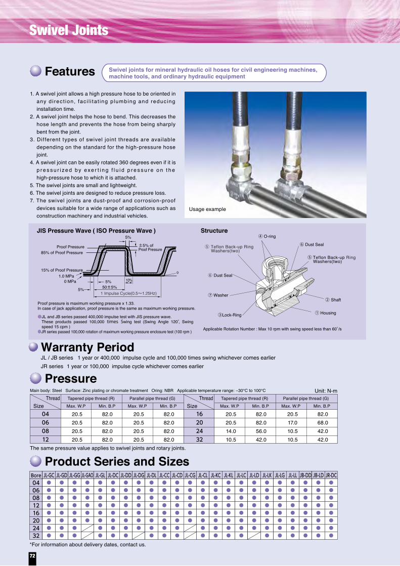
JL-GC JL-GD JL-GG JL-GAO
JL-GL JL-DC JL-DD
JL-DL JL-CC JL-CD
JL-DG
JL-CG
JL-CL JL-KC JL-KL JL-LC
JL-LD JL-LK JL-LG
JB-DD JB-LD JR-DC(rotating joint)
JL-LL
Series
Rc
G
G
G
O-ring seal
G
G
G
G
G
G
G
G
G
Rc
R
G
G
G
Rc
R
G
G
Rc
G
Rc
Rc
R
R
Rc
R
R
G G
Rc
R
G
R
G
R
G
Rc
G
RcR
Rc
Rc
FixedEnd
FixedEnd
FixedEnd
FixedEnd
FixedEnd
FixedEnd
FixedEnd
FixedEnd
FixedEnd
FixedEnd
FixedEnd
FixedEnd
FixedEnd
FixedEnd
FixedEnd
FixedEnd
FixedEnd
FixedEnd
FixedEnd
Fixed End Fixed End
FixedEnd
Swing EndSwing EndSwing EndSwing End
Swing EndSwing End
Swing End
Swing End Swing End
Swing EndSwing End
Swing End Swing EndSwing End
Swing End Swing End
Swing End
Swing End
Swing EndSwing End
Swing EndSwing End
Warranty PeriodJL / JB series 1 year or 400,000 impulse cycle and 100,000 times swing whichever comes earlierJR series 1 year or 100,000 impulse cycle whichever comes earlier
Swivel joints for mineral hydraulic oil hoses for civil engineering machines,machine tools, and ordinary hydraulic equipmentFeatures
Pressure
Product Series and Sizes
Main body: Steel Surface: Zinc plating or chromate treatment Oring: NBR Applicable temperature range: −30°C to 100°C
The same pressure value applies to swivel joints and rotary joints.
*For information about delivery dates, contact us.
1. A swivel joint allows a high pressure hose to be oriented in any d i rec t ion, fac i l i ta t ing p lumbing and reduc ing installation time.
2. A swivel joint helps the hose to bend. This decreases the hose length and prevents the hose from being sharply bent from the joint.
3. Dif ferent types of swivel joint threads are available depending on the standard for the high-pressure hose joint.
4. A swivel joint can be easily rotated 360 degrees even if it is p r e s s u r i z e d b y exe r t i n g f l u i d p r e s s u r e o n t h e high-pressure hose to which it is attached.
5. The swivel joints are small and lightweight.6. The swivel joints are designed to reduce pressure loss.7. The swivel joints are dust-proof and corrosion-proof
devices suitable for a wide range of applications such as construction machinery and industrial vehicles.
SizeTapered pipe thread (R)Max. W.P Min. B.P Max. W.P Min. B.P
Parallel pipe thread (G) Tapered pipe thread (R)Max. W.P Min. B.P Max. W.P Min. B.P
Parallel pipe thread (G)
04060812
Thread
16202432
Bore04
JL-GC JL-GD JL-GG JL-GAO JL-GL JL-DC JL-DD JL-DG JL-DL JL-CC JL-CD JL-CG JL-CL JL-KC JL-KL JL-LC JL-LD JL-LK JL-LG JL-LL JB-DD JB-LD JR-DC
06081216202432
Usage example
20.520.520.520.5
82.082.082.082.0
20.520.520.520.5
82.082.082.082.0
20.520.514.010.5
82.082.056.042.0
20.517.010.510.5
82.068.042.042.0
SizeThread
Unit: N-m
⑤ Teflon Back-up Ring Washers(two)
●JL and JB series passed 400,000 impulse test with JIS pressure wave. These products passed 100,000 times Swing test (Swing Angle 120°, Swing speed 15 cpm )
●JR series passed 100,000 rotation of maximum working pressure enclosure test (100 rpm )
Structure④ O-ring
⑤ Teflon Back-up Ring Washers(two)
⑥ Dust Seal
⑥ Dust Seal
⑦ Washer② Shaft
③Lock-Ring ① Housing
JIS Pressure Wave ( ISO Pressure Wave )
Proof Pressure85% of Proof Pressure
5%
5%50±5%
1 Impulse Cycle(0.5~1.25Hz)
5%
10%1.0 MPa
0 MPa
0
Proof pressure is maximum working pressure x 1.33.In case of jack application, proof pressure is the same as maximum working pressure.
Applicable Rotation Number : Max 10 rpm with swing speed less than 60°/s
15% of Proof Pressure
±5% ofProof Pressure
72
Swivel Joints

JL-GC JL-GD JL-GG JL-GAO
JL-GL JL-DC JL-DD
JL-DL JL-CC JL-CD
JL-DG
JL-CG
JL-CL JL-KC JL-KL JL-LC
JL-LD JL-LK JL-LG
JB-DD JB-LD JR-DC(rotating joint)
JL-LL
Series
Rc
G
G
G
O-ring seal
G
G
G
G
G
G
G
G
G
Rc
R
G
G
G
Rc
R
G
G
Rc
G
Rc
Rc
R
R
Rc
R
R
G G
Rc
R
G
R
G
R
G
Rc
G
RcR
Rc
Rc
FixedEnd
FixedEnd
FixedEnd
FixedEnd
FixedEnd
FixedEnd
FixedEnd
FixedEnd
FixedEnd
FixedEnd
FixedEnd
FixedEnd
FixedEnd
FixedEnd
FixedEnd
FixedEnd
FixedEnd
FixedEnd
FixedEnd
Fixed End Fixed End
FixedEnd
Swing EndSwing EndSwing EndSwing End
Swing EndSwing End
Swing End
Swing End Swing End
Swing EndSwing End
Swing End Swing EndSwing End
Swing End Swing End
Swing End
Swing End
Swing EndSwing End
Swing EndSwing End
Warranty PeriodJL / JB series 1 year or 400,000 impulse cycle and 100,000 times swing whichever comes earlierJR series 1 year or 100,000 impulse cycle whichever comes earlier
Swivel joints for mineral hydraulic oil hoses for civil engineering machines,machine tools, and ordinary hydraulic equipmentFeatures
Pressure
Product Series and Sizes
Main body: Steel Surface: Zinc plating or chromate treatment Oring: NBR Applicable temperature range: −30°C to 100°C
The same pressure value applies to swivel joints and rotary joints.
*For information about delivery dates, contact us.
1. A swivel joint allows a high pressure hose to be oriented in any d i rec t ion, fac i l i ta t ing p lumbing and reduc ing installation time.
2. A swivel joint helps the hose to bend. This decreases the hose length and prevents the hose from being sharply bent from the joint.
3. Dif ferent types of swivel joint threads are available depending on the standard for the high-pressure hose joint.
4. A swivel joint can be easily rotated 360 degrees even if it is p r e s s u r i z e d b y exe r t i n g f l u i d p r e s s u r e o n t h e high-pressure hose to which it is attached.
5. The swivel joints are small and lightweight.6. The swivel joints are designed to reduce pressure loss.7. The swivel joints are dust-proof and corrosion-proof
devices suitable for a wide range of applications such as construction machinery and industrial vehicles.
SizeTapered pipe thread (R)Max. W.P Min. B.P Max. W.P Min. B.P
Parallel pipe thread (G) Tapered pipe thread (R)Max. W.P Min. B.P Max. W.P Min. B.P
Parallel pipe thread (G)
04060812
Thread
16202432
Bore04
JL-GC JL-GD JL-GG JL-GAO JL-GL JL-DC JL-DD JL-DG JL-DL JL-CC JL-CD JL-CG JL-CL JL-KC JL-KL JL-LC JL-LD JL-LK JL-LG JL-LL JB-DD JB-LD JR-DC
06081216202432
Usage example
20.520.520.520.5
82.082.082.082.0
20.520.520.520.5
82.082.082.082.0
20.520.514.010.5
82.082.056.042.0
20.517.010.510.5
82.068.042.042.0
SizeThread
Unit: N-m
⑤ Teflon Back-up Ring Washers(two)
●JL and JB series passed 400,000 impulse test with JIS pressure wave. These products passed 100,000 times Swing test (Swing Angle 120°, Swing speed 15 cpm )
●JR series passed 100,000 rotation of maximum working pressure enclosure test (100 rpm )
Structure④ O-ring
⑤ Teflon Back-up Ring Washers(two)
⑥ Dust Seal
⑥ Dust Seal
⑦ Washer② Shaft
③Lock-Ring ① Housing
JIS Pressure Wave ( ISO Pressure Wave )
Proof Pressure85% of Proof Pressure
5%
5%50±5%
1 Impulse Cycle(0.5~1.25Hz)
5%
10%1.0 MPa
0 MPa
0
Proof pressure is maximum working pressure x 1.33.In case of jack application, proof pressure is the same as maximum working pressure.
Applicable Rotation Number : Max 10 rpm with swing speed less than 60°/s
15% of Proof Pressure
±5% ofProof Pressure
73

Stardard Spring Guard
Standard Spring Guard-Catalog No,8XA○○○ Overall Length Spring Guard-Catalog No,8XB○○○
*To order the overall-length spring guard, change catalog number 8XA○○○ for the standard spring guards below to 8XB○○○.
PA01PA03PA07PA10PA14PA17PA21PA28PA35PF07PF14PF17PF21PFWPFHEQ17EQ21EQ25EQ28EQ31EQ35OKEVWJW7004JW7006JW7008JWMLPWE21NW21WA14WARWJWH21KFKGSPLKA
-
-
-
-
-
-
-
-
-
-
-
-
-
-
-
-
-
-
-
-
-
-
-
-
-
-
-
8XA098
-
-
-
-
-
-
-
-
-
-
-
-
-
-
-
-
-
-
-
-
-
-
-
-
-
-
8XA120
8XA138
8XA180
8XA180
8XA180
8XA180
8XA180
8XA180
8XA180
8XA180
8XA180
8XA180
8XA180
8XA180
8XA180
-
-
-
-
-
-
8XA145
-
8XAJW33
-
-
8XA210
-
8XA180
8XA173
8XA173
8XA173
8XA180
-
8XA160
-
8XA143
8XA160
-
-
-
-
-
-
-
-
-
-
-
-
-
-
-
-
-
-
-
-
-
-
-
-
-
-
-
-
-
-
-
-
-
-
-
-
-
8XA188
02 03 04 05 06 08 10 12 16 20 24 32Hose Size
▲8XA168 ■8XA173▲8XA168 ■8XA173
8XA221
8XA221
8XA221
8XA221
8XA224
8XA224
8XA224
8XA221
8XA221
8XA221
8XA224
8XA224
8XA224
-
-
-
-
-
-
8XA180
-
-
8XA239
-
8XA239
8XA218
8XA224
8XA224
8XA213
8XA213
8XA221
8XA213
8XA210
8XA210
8XA190
8XA203
▲8XA205 ■8XA213▲8XA205 ■8XA213
8XA247
8XA247
8XA247
8XA247
8XA254
8XA254
8XA254
8XA247
8XA247
8XA254
8XA254
8XA254
8XA254
8XA254
8XA254
8XA254
8XA254
8XA254
-
8XA222
-
-
-
8XA254
8XA300
8XA253
8XA254
8XA254
8XA239
8XA239
8XA247
-
8XA258
8XA258
8XA233
8XA258
▲8XA250 ■8XA239▲8XA250 ■8XA239
*Spring codes for these series of factory-crimped couplings.If you are using a different series of couplings from those specified above, contact us.
-
8XA270
8XA305
8XA305
8XA305
8XA305
8XA305
8XA305
8XA305
-
-
-
8XA305
-
-
8XA305
8XA305
8XA305
8XA305
8XA305
8XA340
8XA270
-
-
-
-
-
-
-
-
-
-
-
-
-
-
-
-
-
8XA345
8XA333
8XA333
8XA333
8XA333
8XA333
8XA333
8XA333
-
-
-
8XA333
-
-
8XA333
8XA333
8XA333
8XA333
8XA333
8XA333
8XA320
-
-
-
-
-
8XA330
8XA355
-
-
-
8XA333
-
8XA317
-
-
8XA317
-
8XA400
8XA410
8XA410
8XA410
8XA410
8XA410
8XA410
8XA415
-
-
-
8XA410
-
-
8XA410
8XA410
8XA410
8XA410
8XA415
8XA415
8XA395
8XA400
-
-
-
-
8XA410
8XA415
-
-
-
8XA410
-
-
-
-
-
-
8XA505
8XA520
8XA520
8XA520
-
8XA520
8XA520
8XA548
-
-
-
-
-
-
8XA520
8XA520
8XA520
8XA548
8XA548
8XA631
8XA500
8XA505
-
-
-
-
-
8XA548
-
-
-
-
-
-
-
-
-
-
8XA560
8XA545
8XA545
8XA567
-
8XA567
8XA665
8XA665
-
-
-
-
-
-
8XA567
8XA567
8XA665
8XA665
8XA665
-
8XA570
8XA560
-
-
-
-
-
8XA665
-
-
-
-
-
-
-
-
-
-
-
8XA735
8XA735
8XA735
-
8XA735
8XA820
8XA800
-
-
-
-
-
-
-
8XA780
-
-
8XA800
8XA800
8XA720
8XA727
-
-
-
-
8XA735
8XA780
-
-
-
-
-
-
-
-
-
For factory-crimped products
1. Check the applicable couplings. They should be the series of devices shown in this catalog.
2. The markings prefixed to certain product names indicate the springs for those series of couplings, as follows.
▲…Spring for AS■…Spring for UL
Hose Series
For information about the methodof indicating the catalog numbers, refer to page 76.
Notes
Plastic Guard-Catalog No,8XE○○○
Standard Spring Guard-Catalog No,8XA○○○
For the protection for hose entire length from external damage.
■For the protection of the crimped portion.
8XAStandard Spring
213Inner Diameter of Spring Guard. (213 : spring I.D.=21.3mm)Refer to the chart in pp. 58-59 for the combination of hose and spring I.D.
Example
Braided Steel Wire■For the protection for hose entire length from external damage.
PA1408-GGPut "-GG" at the end of hose catalog No.For Braid Stainless Steel Wire, put "-SS".
EQ1712-GAPut "-○○" (shown above) at the end of hose catalog No.
Example
Glass-Wool + Braided Steel Wire
Overall Length Spring Guard-Catalog No,8XB○○○■For the protection for hose entire length from external damage■If the overall-length spring guard is ordered, the first three characters of the catalog number are changed from 8XA
for the standard spring above to 8XB.
8XBOverall Length
160Inner Diameter of Spring Guard. (160 : spring I.D.=16.0mm)Refer to the chart in pp. 59 for the combination of hose and spring I.D.
*The length tolerance for exterior equipment is up to 5% of the product length.
*The length tolerance for exterior equipment is up to 5% of the product length.
*The length tolerance for exterior equipment is up to 5% of the product length.
Sample markings (for factory-crimped PA0706)
GAGWGNSA
1 layer of Glass Wool +1layer of Braided Steel Wire.2 layer of Glass Wool +1layer of Braided Steel Wire.3 layer of Glass Wool +1layer of Braided Steel Wire.1 layer of Glass Wool +1layer of Braided Stainless Steel Wire.
Sample markings (for factory-crimped KF04)
Exterior glass wool is effective in protecting the hose against momentary fires and high temperatures. It may not exhibit the expected heat insulating effect if it is used continuously at a high temperature.
74
Accessories for Protection
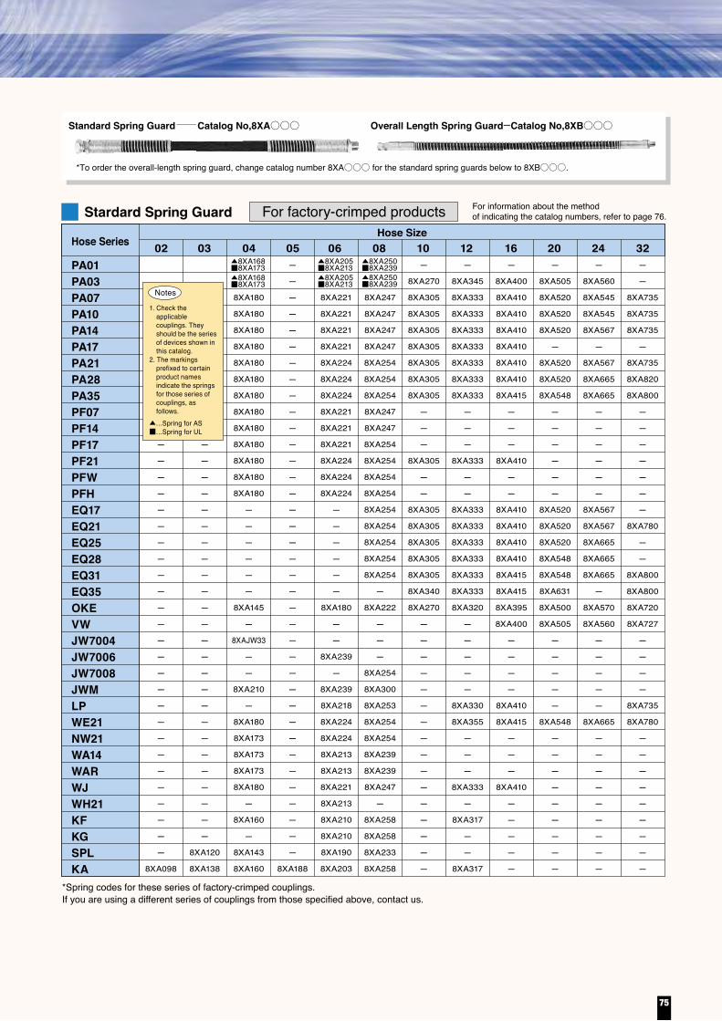
Stardard Spring Guard
Standard Spring Guard-Catalog No,8XA○○○ Overall Length Spring Guard-Catalog No,8XB○○○
*To order the overall-length spring guard, change catalog number 8XA○○○ for the standard spring guards below to 8XB○○○.
PA01PA03PA07PA10PA14PA17PA21PA28PA35PF07PF14PF17PF21PFWPFHEQ17EQ21EQ25EQ28EQ31EQ35OKEVWJW7004JW7006JW7008JWMLPWE21NW21WA14WARWJWH21KFKGSPLKA
-
-
-
-
-
-
-
-
-
-
-
-
-
-
-
-
-
-
-
-
-
-
-
-
-
-
-
8XA098
-
-
-
-
-
-
-
-
-
-
-
-
-
-
-
-
-
-
-
-
-
-
-
-
-
-
8XA120
8XA138
8XA180
8XA180
8XA180
8XA180
8XA180
8XA180
8XA180
8XA180
8XA180
8XA180
8XA180
8XA180
8XA180
-
-
-
-
-
-
8XA145
-
8XAJW33
-
-
8XA210
-
8XA180
8XA173
8XA173
8XA173
8XA180
-
8XA160
-
8XA143
8XA160
-
-
-
-
-
-
-
-
-
-
-
-
-
-
-
-
-
-
-
-
-
-
-
-
-
-
-
-
-
-
-
-
-
-
-
-
-
8XA188
02 03 04 05 06 08 10 12 16 20 24 32Hose Size
▲8XA168 ■8XA173▲8XA168 ■8XA173
8XA221
8XA221
8XA221
8XA221
8XA224
8XA224
8XA224
8XA221
8XA221
8XA221
8XA224
8XA224
8XA224
-
-
-
-
-
-
8XA180
-
-
8XA239
-
8XA239
8XA218
8XA224
8XA224
8XA213
8XA213
8XA221
8XA213
8XA210
8XA210
8XA190
8XA203
▲8XA205 ■8XA213▲8XA205 ■8XA213
8XA247
8XA247
8XA247
8XA247
8XA254
8XA254
8XA254
8XA247
8XA247
8XA254
8XA254
8XA254
8XA254
8XA254
8XA254
8XA254
8XA254
8XA254
-
8XA222
-
-
-
8XA254
8XA300
8XA253
8XA254
8XA254
8XA239
8XA239
8XA247
-
8XA258
8XA258
8XA233
8XA258
▲8XA250 ■8XA239▲8XA250 ■8XA239
*Spring codes for these series of factory-crimped couplings.If you are using a different series of couplings from those specified above, contact us.
-
8XA270
8XA305
8XA305
8XA305
8XA305
8XA305
8XA305
8XA305
-
-
-
8XA305
-
-
8XA305
8XA305
8XA305
8XA305
8XA305
8XA340
8XA270
-
-
-
-
-
-
-
-
-
-
-
-
-
-
-
-
-
8XA345
8XA333
8XA333
8XA333
8XA333
8XA333
8XA333
8XA333
-
-
-
8XA333
-
-
8XA333
8XA333
8XA333
8XA333
8XA333
8XA333
8XA320
-
-
-
-
-
8XA330
8XA355
-
-
-
8XA333
-
8XA317
-
-
8XA317
-
8XA400
8XA410
8XA410
8XA410
8XA410
8XA410
8XA410
8XA415
-
-
-
8XA410
-
-
8XA410
8XA410
8XA410
8XA410
8XA415
8XA415
8XA395
8XA400
-
-
-
-
8XA410
8XA415
-
-
-
8XA410
-
-
-
-
-
-
8XA505
8XA520
8XA520
8XA520
-
8XA520
8XA520
8XA548
-
-
-
-
-
-
8XA520
8XA520
8XA520
8XA548
8XA548
8XA631
8XA500
8XA505
-
-
-
-
-
8XA548
-
-
-
-
-
-
-
-
-
-
8XA560
8XA545
8XA545
8XA567
-
8XA567
8XA665
8XA665
-
-
-
-
-
-
8XA567
8XA567
8XA665
8XA665
8XA665
-
8XA570
8XA560
-
-
-
-
-
8XA665
-
-
-
-
-
-
-
-
-
-
-
8XA735
8XA735
8XA735
-
8XA735
8XA820
8XA800
-
-
-
-
-
-
-
8XA780
-
-
8XA800
8XA800
8XA720
8XA727
-
-
-
-
8XA735
8XA780
-
-
-
-
-
-
-
-
-
For factory-crimped products
1. Check the applicable couplings. They should be the series of devices shown in this catalog.
2. The markings prefixed to certain product names indicate the springs for those series of couplings, as follows.
▲…Spring for AS■…Spring for UL
Hose Series
For information about the methodof indicating the catalog numbers, refer to page 76.
Notes
Plastic Guard-Catalog No,8XE○○○
Standard Spring Guard-Catalog No,8XA○○○
For the protection for hose entire length from external damage.
■For the protection of the crimped portion.
8XAStandard Spring
213Inner Diameter of Spring Guard. (213 : spring I.D.=21.3mm)Refer to the chart in pp. 58-59 for the combination of hose and spring I.D.
Example
Braided Steel Wire■For the protection for hose entire length from external damage.
PA1408-GGPut "-GG" at the end of hose catalog No.For Braid Stainless Steel Wire, put "-SS".
EQ1712-GAPut "-○○" (shown above) at the end of hose catalog No.
Example
Glass-Wool + Braided Steel Wire
Overall Length Spring Guard-Catalog No,8XB○○○■For the protection for hose entire length from external damage■If the overall-length spring guard is ordered, the first three characters of the catalog number are changed from 8XA
for the standard spring above to 8XB.
8XBOverall Length
160Inner Diameter of Spring Guard. (160 : spring I.D.=16.0mm)Refer to the chart in pp. 59 for the combination of hose and spring I.D.
*The length tolerance for exterior equipment is up to 5% of the product length.
*The length tolerance for exterior equipment is up to 5% of the product length.
*The length tolerance for exterior equipment is up to 5% of the product length.
Sample markings (for factory-crimped PA0706)
GAGWGNSA
1 layer of Glass Wool +1layer of Braided Steel Wire.2 layer of Glass Wool +1layer of Braided Steel Wire.3 layer of Glass Wool +1layer of Braided Steel Wire.1 layer of Glass Wool +1layer of Braided Stainless Steel Wire.
Sample markings (for factory-crimped KF04)
Exterior glass wool is effective in protecting the hose against momentary fires and high temperatures. It may not exhibit the expected heat insulating effect if it is used continuously at a high temperature.
75

8 9 10
1 2 3
● For information about the method of indicating assembly hose lengths, refer to “Example Indications of Hose Length and Orientation Angle” on page 5. For dimensions of fittings, refer to the specifications of the coupling dimensions for each series of hose. ● If you need to use a hose with exterior protection, consult us. ● Minimum exposed lengths may differ from the values above depending on the combination of hoses and couplings.
●Exposed hose length: R=π(r+D/2)+2D
rr
U-shaped hose fixed at both ends
1
●Exposed hose length: R=π(r+D/2)+2D+T
U-shaped hose fixed at one end,the other end moved by T
●Same as above
Min. exposed length of hosethat can be manufactured
R: Exposed hose length r: Minimum bending hose radius T: Distance π: Circular constant D: Hose external diameter
Hose Series(mm) 02Actual hose internal diameter 3.2
150ー
034.8150200
046.3150200
057.9150200
069.5160200
0812.7170200
1015.9180200
1219.0190210
1625.4210210
2031.8220ー
2438.1350ー
3250.8370ー
4063.5400ー
4876.2400ー
Min. exposed length of hose thatcan be manufactured Bridgestone
PrimoLine
If the bending radius falls below the required minimum, install an elbow adapter as shown above to avoid sharp bends in the hose.
2
Use an adapter to avoid sharp twists or bends in the hose.
3
To avoid twists, bend the hose on the s am e p lane a s t h e d i r e c t i on o f movement of the base to which the hose is connected.
4
Obtain direct rout ing of hoses by using an adapter. You can arrange the hoses neatly by avoiding the use of excessively long hoses.
5 6 7
There will be some change in length when the hose is pressurized. Do not clamp the hose at the bends in an attempt to avoid the length change. (If the piping design cannot be changed, protect the hose with springs and external wire braid instead of clamping.)
The hose should have an adequate amount of slack.This slack permits smooth hose movement and prevents sharp bends in the hose.
The length of a hose changes by about 4% when it is under pressure. Provide an adequate amount of slack to allow for expansion and contraction.
Three-plane bending could result in the hose developing twists when it is under pressure. When the hose moves as shown in the figure on the left, it always twists. Therefore, using the attached tool, clamp the hose so that it moves on only one plane to prevent it from developing twists.
Minimum exposed length of hoses that can be manufactured
By selecting appropriate adapters, you can decrease the number of coupling par ts and thereby improve the seal reliability and coupling appearance.
Use the lay line provided on the hose as a reference to examine whether or not the installed hose is twisted. Also, when using a coupling equipped with a union nut, be sure to fix it by tightening the hexagonal portion of the torsion preventive part with a wrench.
Hose Assembly Installation
Overall Length Spring Guard
PA01PA03PA07PA10PA14PA17PA21PA28PA35PFHEQ17EQ21EQ25EQ28EQ31EQ35OKEWA14WARWJKFKGSPLKAKBAG10WSH
04 06 08 10 12 16 20 24 32Hose Size
8XB180MA
8XB180MA
8XB180MA
8XB180MA
8XB180MA
8XB180MA
8XB180MA
8XB180MA
-
-
-
-
-
-
8XB150MA
8XB170MA
8XB170MA
8XB180MA
8XB160MA
-
8XB143MA
8XB170MA
8XB170MA
8XB143MA
8XB160MA
8XB215MA
8XB215MA
8XB215MA
8XB215MA
8XB215MA
8XB215MA
8XB215MA
8XB215MA
-
-
-
-
-
-
8XB180MA
8XB215MA
8XB215MA
8XB215MA
8XB210MA
8XB210MA
8XB200MA
8XB215MA
8XB215MA
8XB200MA
8XB210MA
8XB260MA
8XB260MA
8XB260MA
8XB260MA
8XB260MA
8XB260MA
8XB260MA
8XB260MA
8XB260MA
8XB260MA
8XB260MA
8XB260MA
8XB260MA
8XB260MA
8XB226MA
8XB239MA
8XB239MA
8XB260MA
8XB258MA
8XB258MA
8XB244MA
8XB239MA
8XB239MA
8XB244MA
-
-
8XB284MA
8XB300MA
8XB300MA
8XB300MA
8XB300MA
8XB300MA
8XB300MA
8XB300MA
-
8XB300MA
8XB300MA
8XB300MA
8XB300MA
8XB300MA
-
8XB273MA
-
-
-
-
-
-
-
-
-
-
-
8XB355MA
8XB340MA
8XB340MA
8XB340MA
8XB340MA
8XB340MA
8XB340MA
8XB340MA
-
8XB340MA
8XB340MA
8XB340MA
8XB340MA
8XB340MA
8XB340MA
8XB310MA
-
-
8XB340MA
8XB340MA
-
-
8XB340MA
8XB340MA
-
-
-
8XB400MA
8XB410MA
8XB410MA
8XB410MA
8XB410MA
8XB410MA
8XB410MA
8XB410MA
-
8XB410MA
8XB410MA
8XB410MA
8XB410MA
8XB410MA
8XB410MA
8XB390MA
-
-
8XB410MA
-
-
-
-
8XB430MA
-
-
-
8XB505MA
8XB538MA
8XB538MA
8XB538MA
-
8XB538MA
8XB538MA
8XB538MA
-
8XB538MA
8XB538MA
8XB538MA
8XB538MA
8XB538MA
-
8XB500MA
-
-
-
-
-
-
-
-
-
-
-
8XB560MA
8XB555MA
8XB555MA
8XB580MA
-
8XB580MA
-
-
-
8XB580MA
8XB580MA
-
-
-
-
8XB570MA
-
-
-
-
-
8XB740MA
8XB745MA
8XB745MA
-
8XB745MA
-
-
-
-
-
-
-
-
-
8XB720MA
-
-
-
▲8XB168MA ■8XB170MA▲8XB168MA ■8XB170MA
▲8XB260MA ■8XB239MA▲8XB260MA■8XB239MA
▲8XB210MA ■8XB215MA▲8XB210MA ■8XB215MA
KBAG10PSPCWSHJC70SFJAMJALJAKJKY
-
-
-
-
-
-
-
-
-
-
-
8XA138
-
8XA138
-
-
8XA188
-
8XA235
8XA180D25
-
-
8XA160
8XA143
8XA160
8XA160
8XA160
-
8XA145
-
8XA185D25
8XA190D25
8XA190D25
8XA185
-
8XA185
-
-
-
-
8XA256
8XA210
8XA205
-
8XA317
-
-
-
-
-
-
-
8XA400
-
-
8XA210
8XA190
-
-
8XA210
-
8XA195
-
8XA240
8XA240
-
8XA258
8XA233
-
-
-
-
8XA240
-
8XA302
8XA280
-
-
-
-
-
-
-
8XA253
-
8XA356
-
-
8XA408
-
-
-
-
-
-
-
8XA456
-
-
-
-
-
-
-
-
-
-
-
-
-
02 03 04 05 06 08 10 12 16 20 24 32Hose Size
*Spring codes for these series of factory-crimped couplings.If you are using a different series of couplings from those specified above, contact us.
*Spring codes for these series of factory-crimped couplings.If you are using a different series of couplings from those specified above, contact us.
-
-
-
-
-
-
-
-
-
-
-
-
-
-
-
-
-
-
-
-
-
-
Hose Series
Hose Series
1. Check the applicable couplings. They should be the series of devices shown in this catalog.
2. The markings prefixed to certain product names indicate the springs for those series of couplings, as follows.
▲…Spring for AS■…Spring for UL
For UNICRIMP-crimped products For information about the methodof indicating the catalog numbers, refer to page 70.
Notes
76
Accessories for Protection

8 9 10
1 2 3
● For information about the method of indicating assembly hose lengths, refer to “Example Indications of Hose Length and Orientation Angle” on page 5. For dimensions of fittings, refer to the specifications of the coupling dimensions for each series of hose. ● If you need to use a hose with exterior protection, consult us. ● Minimum exposed lengths may differ from the values above depending on the combination of hoses and couplings.
●Exposed hose length: R=π(r+D/2)+2D
rr
U-shaped hose fixed at both ends
1
●Exposed hose length: R=π(r+D/2)+2D+T
U-shaped hose fixed at one end,the other end moved by T
●Same as above
Min. exposed length of hosethat can be manufactured
R: Exposed hose length r: Minimum bending hose radius T: Distance π: Circular constant D: Hose external diameter
Hose Series(mm) 02Actual hose internal diameter 3.2
150ー
034.8150200
046.3150200
057.9150200
069.5160200
0812.7170200
1015.9180200
1219.0190210
1625.4210210
2031.8220ー
2438.1350ー
3250.8370ー
4063.5400ー
4876.2400ー
Min. exposed length of hose thatcan be manufactured Bridgestone
PrimoLine
If the bending radius falls below the required minimum, install an elbow adapter as shown above to avoid sharp bends in the hose.
2
Use an adapter to avoid sharp twists or bends in the hose.
3
To avoid twists, bend the hose on the s am e p lane a s t h e d i r e c t i on o f movement of the base to which the hose is connected.
4
Obtain direct rout ing of hoses by using an adapter. You can arrange the hoses neatly by avoiding the use of excessively long hoses.
5 6 7
There will be some change in length when the hose is pressurized. Do not clamp the hose at the bends in an attempt to avoid the length change. (If the piping design cannot be changed, protect the hose with springs and external wire braid instead of clamping.)
The hose should have an adequate amount of slack.This slack permits smooth hose movement and prevents sharp bends in the hose.
The length of a hose changes by about 4% when it is under pressure. Provide an adequate amount of slack to allow for expansion and contraction.
Three-plane bending could result in the hose developing twists when it is under pressure. When the hose moves as shown in the figure on the left, it always twists. Therefore, using the attached tool, clamp the hose so that it moves on only one plane to prevent it from developing twists.
Minimum exposed length of hoses that can be manufactured
By selecting appropriate adapters, you can decrease the number of coupling par ts and thereby improve the seal reliability and coupling appearance.
Use the lay line provided on the hose as a reference to examine whether or not the installed hose is twisted. Also, when using a coupling equipped with a union nut, be sure to fix it by tightening the hexagonal portion of the torsion preventive part with a wrench.
Hose Assembly Installation
Overall Length Spring Guard
PA01PA03PA07PA10PA14PA17PA21PA28PA35PFHEQ17EQ21EQ25EQ28EQ31EQ35OKEWA14WARWJKFKGSPLKAKBAG10WSH
04 06 08 10 12 16 20 24 32Hose Size
8XB180MA
8XB180MA
8XB180MA
8XB180MA
8XB180MA
8XB180MA
8XB180MA
8XB180MA
-
-
-
-
-
-
8XB150MA
8XB170MA
8XB170MA
8XB180MA
8XB160MA
-
8XB143MA
8XB170MA
8XB170MA
8XB143MA
8XB160MA
8XB215MA
8XB215MA
8XB215MA
8XB215MA
8XB215MA
8XB215MA
8XB215MA
8XB215MA
-
-
-
-
-
-
8XB180MA
8XB215MA
8XB215MA
8XB215MA
8XB210MA
8XB210MA
8XB200MA
8XB215MA
8XB215MA
8XB200MA
8XB210MA
8XB260MA
8XB260MA
8XB260MA
8XB260MA
8XB260MA
8XB260MA
8XB260MA
8XB260MA
8XB260MA
8XB260MA
8XB260MA
8XB260MA
8XB260MA
8XB260MA
8XB226MA
8XB239MA
8XB239MA
8XB260MA
8XB258MA
8XB258MA
8XB244MA
8XB239MA
8XB239MA
8XB244MA
-
-
8XB284MA
8XB300MA
8XB300MA
8XB300MA
8XB300MA
8XB300MA
8XB300MA
8XB300MA
-
8XB300MA
8XB300MA
8XB300MA
8XB300MA
8XB300MA
-
8XB273MA
-
-
-
-
-
-
-
-
-
-
-
8XB355MA
8XB340MA
8XB340MA
8XB340MA
8XB340MA
8XB340MA
8XB340MA
8XB340MA
-
8XB340MA
8XB340MA
8XB340MA
8XB340MA
8XB340MA
8XB340MA
8XB310MA
-
-
8XB340MA
8XB340MA
-
-
8XB340MA
8XB340MA
-
-
-
8XB400MA
8XB410MA
8XB410MA
8XB410MA
8XB410MA
8XB410MA
8XB410MA
8XB410MA
-
8XB410MA
8XB410MA
8XB410MA
8XB410MA
8XB410MA
8XB410MA
8XB390MA
-
-
8XB410MA
-
-
-
-
8XB430MA
-
-
-
8XB505MA
8XB538MA
8XB538MA
8XB538MA
-
8XB538MA
8XB538MA
8XB538MA
-
8XB538MA
8XB538MA
8XB538MA
8XB538MA
8XB538MA
-
8XB500MA
-
-
-
-
-
-
-
-
-
-
-
8XB560MA
8XB555MA
8XB555MA
8XB580MA
-
8XB580MA
-
-
-
8XB580MA
8XB580MA
-
-
-
-
8XB570MA
-
-
-
-
-
8XB740MA
8XB745MA
8XB745MA
-
8XB745MA
-
-
-
-
-
-
-
-
-
8XB720MA
-
-
-
▲8XB168MA ■8XB170MA▲8XB168MA ■8XB170MA
▲8XB260MA ■8XB239MA▲8XB260MA■8XB239MA
▲8XB210MA ■8XB215MA▲8XB210MA ■8XB215MA
KBAG10PSPCWSHJC70SFJAMJALJAKJKY
-
-
-
-
-
-
-
-
-
-
-
8XA138
-
8XA138
-
-
8XA188
-
8XA235
8XA180D25
-
-
8XA160
8XA143
8XA160
8XA160
8XA160
-
8XA145
-
8XA185D25
8XA190D25
8XA190D25
8XA185
-
8XA185
-
-
-
-
8XA256
8XA210
8XA205
-
8XA317
-
-
-
-
-
-
-
8XA400
-
-
8XA210
8XA190
-
-
8XA210
-
8XA195
-
8XA240
8XA240
-
8XA258
8XA233
-
-
-
-
8XA240
-
8XA302
8XA280
-
-
-
-
-
-
-
8XA253
-
8XA356
-
-
8XA408
-
-
-
-
-
-
-
8XA456
-
-
-
-
-
-
-
-
-
-
-
-
-
02 03 04 05 06 08 10 12 16 20 24 32Hose Size
*Spring codes for these series of factory-crimped couplings.If you are using a different series of couplings from those specified above, contact us.
*Spring codes for these series of factory-crimped couplings.If you are using a different series of couplings from those specified above, contact us.
-
-
-
-
-
-
-
-
-
-
-
-
-
-
-
-
-
-
-
-
-
-
Hose Series
Hose Series
1. Check the applicable couplings. They should be the series of devices shown in this catalog.
2. The markings prefixed to certain product names indicate the springs for those series of couplings, as follows.
▲…Spring for AS■…Spring for UL
For UNICRIMP-crimped products For information about the methodof indicating the catalog numbers, refer to page 70.
Notes
77
How to calculate Hose Exposed Length
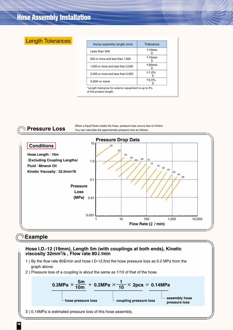
Relational Table of FlowRate/Velocity/Internal Hose Diameter By using this table, you can easily determinethe internal diameter of the hose, as follows.
120
2
3
30
40
50
60708090
100
4
56789
10
20
30
40
5060708090
200
300
400
500
600700800900
1000
2000
3000
4000
5000
6000700080009000
100
10000
200
300
400
500600700800900
1000
0.01
0.02
0.04
0.06
0.08
0.1
0.2
0.3
0.4
0.6
0.81
2
34
68
Recommendableflow velocity range
10
20
3040
6080
100
30
20
10987
6
5
4
3
2
1
0.8
0.6
0.4
0.2
0.1
32
24
20
16
12
10
08
06
05
04
03
Hose internal diameter (in 1/16-inch increments)
Determining the internal diameter of a hose to supply liquid at a flow rate of 30 litters/minuteAt first, put the mark at 30 litters/minute on "FLOW RATE" graph. Next, mark at 2 to 8 meters/second on "VELOCITY" graph. Then line out from mark of FLOW RATE to mark of VELOCITY and directly extend to " Hose internal ciameter" graph. Recommended hose diameter is between cross point by extended lines.In this case, recommended diameter is " 06 ( 3/4 inches )" to " 10 ( 5/8" inches) " SIZE.
/min, FLOW RATE cm3/sec
VELOCITY m/sec
SECTIONAL AREAOF HOSE(cm2)
Q = 0.0471Vd2
Q : FLOW RATE ( /min)V : VELOCITY (m/min)d : HOSE SIZE:ID.(mm)
The equation below shows the relationship between flow rates, velocities, and internal diameters.
When a liquid flows inside the hose, pressure loss occurs due to friction.You can calculate the approximate pressure loss as follows.
1.0
10
0.1
0.01
0.0011 10 100 1,000 10,000
02
03
0405
06 08 1012
1620
2432
4048
Pressure Loss
Length TolerancesHorse assembly length (mm) Tolerance
Less than 500
500 or more and less than 1,000
1,000 or more and less than 2,000
2,000 or more and less than 5,000
5,000 or more
+10mm
+15mm
+20mm
+1.0%
+2.0%
0
0
0
0
0*Length tolerance for exterior equipment is up to 5% of the product length.
Example
ConditionsHose Length : 10m
(Excluding Coupling Lengths)Fluid : Mineral OilKinetic Viscosity : 32.0mm2/S
PressureLoss(MPa)
Flow Rate ( / min)
Hose I.D.-12 (19mm), Length 5m (with couplings at both ends), Kinetic viscosity 32mm2/s , Flow rate 80 /min
3 ) 0.14MPa is estimated pressure loss of this hose assembly.
hose pressure loss coupling pressure loss
5m10m0.2MPa × + 0.2MPa × × 2pcs = 0.14MPa1
10
assembly hosepressure loss
Pressure Drop Data
1 ) By the flow rate 80ℓ/min and hose I.D-12,find the hose pressure loss as 0.2 MPa from the graph above.
2 ) Pressure loss of a coupling is about the same as 1/10 of that of the hose.
78
Hose Assembly Installation

Relational Table of FlowRate/Velocity/Internal Hose Diameter By using this table, you can easily determinethe internal diameter of the hose, as follows.
120
2
3
30
40
50
60708090
100
4
56789
10
20
30
40
5060708090
200
300
400
500
600700800900
1000
2000
3000
4000
5000
6000700080009000
100
10000
200
300
400
500600700800900
1000
0.01
0.02
0.04
0.06
0.08
0.1
0.2
0.3
0.4
0.6
0.81
2
34
68
Recommendableflow velocity range
10
20
3040
6080
100
30
20
10987
6
5
4
3
2
1
0.8
0.6
0.4
0.2
0.1
32
24
20
16
12
10
08
06
05
04
03
Hose internal diameter (in 1/16-inch increments)
Determining the internal diameter of a hose to supply liquid at a flow rate of 30 litters/minuteAt first, put the mark at 30 litters/minute on "FLOW RATE" graph. Next, mark at 2 to 8 meters/second on "VELOCITY" graph. Then line out from mark of FLOW RATE to mark of VELOCITY and directly extend to " Hose internal ciameter" graph. Recommended hose diameter is between cross point by extended lines.In this case, recommended diameter is " 06 ( 3/4 inches )" to " 10 ( 5/8" inches) " SIZE.
/min, FLOW RATE cm3/sec
VELOCITY m/sec
SECTIONAL AREAOF HOSE(cm2)
Q = 0.0471Vd2
Q : FLOW RATE ( /min)V : VELOCITY (m/min)d : HOSE SIZE:ID.(mm)
The equation below shows the relationship between flow rates, velocities, and internal diameters.
When a liquid flows inside the hose, pressure loss occurs due to friction.You can calculate the approximate pressure loss as follows.
1.0
10
0.1
0.01
0.0011 10 100 1,000 10,000
02
03
0405
06 08 1012
1620
2432
4048
Pressure Loss
Length TolerancesHorse assembly length (mm) Tolerance
Less than 500
500 or more and less than 1,000
1,000 or more and less than 2,000
2,000 or more and less than 5,000
5,000 or more
+10mm
+15mm
+20mm
+1.0%
+2.0%
0
0
0
0
0*Length tolerance for exterior equipment is up to 5% of the product length.
Example
ConditionsHose Length : 10m
(Excluding Coupling Lengths)Fluid : Mineral OilKinetic Viscosity : 32.0mm2/S
PressureLoss(MPa)
Flow Rate ( / min)
Hose I.D.-12 (19mm), Length 5m (with couplings at both ends), Kinetic viscosity 32mm2/s , Flow rate 80 /min
3 ) 0.14MPa is estimated pressure loss of this hose assembly.
hose pressure loss coupling pressure loss
5m10m0.2MPa × + 0.2MPa × × 2pcs = 0.14MPa1
10
assembly hosepressure loss
Pressure Drop Data
1 ) By the flow rate 80ℓ/min and hose I.D-12,find the hose pressure loss as 0.2 MPa from the graph above.
2 ) Pressure loss of a coupling is about the same as 1/10 of that of the hose.
79
Relational Table of Flow Rate / Velocity / Hose Size

1. Witness inspection is required each time a product is tested for certification by an organization other than CR, ABS, or DNV. Contact us.2. When a product to be used inside an engine room is tested for certification by Bureau Veritas (BV), an external wire braid is
required for that product.
Our products have obtained a certificate of compliance with the marine standard, as shown below. Since then, they have earned a worldwide reputation.
Products Certified for Compliance with the Marine StandardStandard
Hose
PA0704~32
PA1004~32
PA1404~32
PA1704~16
PA2104~32
PA2804~32
EQ1708~24
EQ2108~32
EQ2508~24
EQ2808~24
EQ3108~32
NK(Japan)
Nippon Kaiji Kyokai
JG(Japan)
MLIT Maritime Bureau
LR(U.K.)
Lloyd's Register of Shipping
BV(France)
Bureau Veritas
DNV(Norway)Det Norske
Veritas
KR(Korea)
Korean Bureau of Shipping
CR(Taiwan)
Central Research of Shipping S.A.
ABS(U.S.A)
American Bureau of Shipping
CCS(China)
China Classification Society
◎
◎
◎
◎
◎
◎
◎
◎
◎
◎
◎
◎
◎
◎
◎
◎
◎
◎
◎
◎
◎
◎
◎
◎
◎
◎
◎
◎
◎
◎
◎
◎
◎
◎
◎
◎
◎
◎
◎
◎
◎
◎
◎
◎
◎
◎
◎
◎
◎
◎
◎
◎
◎
◎
◎
20~32
20~32
20~32
-
20~32
◎
◎
◎
◎
◎
◎
◎
◎
◎
◎
◎
◎
◎
◎
◎
◎
◎
◎
◎
◎
◎
◎
◎
◎
◎
◎
◎
◎
For certified sizes, contact us.
322420161210080605040302
21 1 13/41/23/81/41/8Pipe Thread
F / C type
15 ー ー
70*29 140 210 250 310 620
ー ー ー
ー
ーPipe threadR type
Torque N / m
Coupling
Bolt for Split Frange(Material : Steel)
Bolt for JIS Frange(Material : Steel)
Coupling(Material : Steel / Surface : Zinc Plating・Chromate Treatment)Hose
/41 /2
1
ー ー 20 29 39 49 59 118 137 167 ー ー
ー
ー ー 25 ー 49 78 137 176 196 ー ー ー
ー
ー
ー ー M14×1.5 ー M18×1.5 M22×1.5 M24×1.5 M30×1.5 M33×1.5 ー ーM thread
ー ー 39 ー 67 78 118 157 196 327 430
ー ー ー
ー ー ー ーUNF thread
UNF thread
/167
41225522519613264*29
34*25
25*1515
08
8YA08S
10
8YA12S
12 16 20
8YA20S
24
8YA24S
32
Catalog No.
20~25 28~40 48~62 62~79 73~90
8YA32H
271~294
37~48
8YA08S 8YA12H 8YA20H 8YA24H8YA16H
20~25 33~45 85~102 151~18156~68
For StandardPressure
08
8YAK15Catalog No.
34~45
10 12 16
8YAK25
54~76
8YAK40
147~230
20 24 32 40
8YAK65
314~451
48
8YAK80
470~637For JIS21MPa
(210kgf/cm2)
ー20
/169 ー18 /16
11 ー16 /1613 ー16 1ー14 2ー12
/21 ー20 /4
3 ー16 /87 ー14 /16
1 ー121 /165 ー121 /8
5 ー121
/163 ー121 /16
7 ー121 /1611 ー121
/169 ー18
F2 / F3 type
F4 type
Q2 type
Torque N / m
Torque N / m
Torque N / m
Torque N / m
Torque N / m
Catalog No.
Torque N / m
Coupling Hose
Coupling Hose
For HighPressure
Torque N / m
●Follow the below tightening torque.●The tolerance is approximately ± 10%.●The application of each of the following torques is allowed on the prerequisite that there is no oil left on the threads portion
and inside of the nut and also that the hexagonal part of each insert is firmly held by a spanner so as to prevent the coupling from rotating together with hose.
● For proper tightening , use a torque wrench (shown below)
When a split flange or a square flange is used for a hose connection, the bolts must be tightened diagonally with the same torque applied. Otherwise, the flange will incur damage, possibly followed by oil leakage.
40*25
40*15
*Products marked with an asterisk are the F- and R-type couplings made of brass. *1:The tightening torque for the R joint varies depending on how its sealing tape is wrapped. Therefore, the values above are for reference only.
*For tightening torques for PrimoLine, refer to page 57. *Use a torque wrench for proper tightening.
*1 Referencevalues( )
Warning
80
Tightening Torque
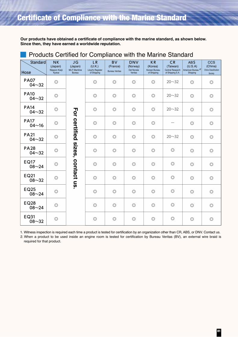
1. Witness inspection is required each time a product is tested for certification by an organization other than CR, ABS, or DNV. Contact us.2. When a product to be used inside an engine room is tested for certification by Bureau Veritas (BV), an external wire braid is
required for that product.
Our products have obtained a certificate of compliance with the marine standard, as shown below. Since then, they have earned a worldwide reputation.
Products Certified for Compliance with the Marine StandardStandard
Hose
PA0704~32
PA1004~32
PA1404~32
PA1704~16
PA2104~32
PA2804~32
EQ1708~24
EQ2108~32
EQ2508~24
EQ2808~24
EQ3108~32
NK(Japan)
Nippon Kaiji Kyokai
JG(Japan)
MLIT Maritime Bureau
LR(U.K.)
Lloyd's Register of Shipping
BV(France)
Bureau Veritas
DNV(Norway)Det Norske
Veritas
KR(Korea)
Korean Bureau of Shipping
CR(Taiwan)
Central Research of Shipping S.A.
ABS(U.S.A)
American Bureau of Shipping
CCS(China)
China Classification Society
◎
◎
◎
◎
◎
◎
◎
◎
◎
◎
◎
◎
◎
◎
◎
◎
◎
◎
◎
◎
◎
◎
◎
◎
◎
◎
◎
◎
◎
◎
◎
◎
◎
◎
◎
◎
◎
◎
◎
◎
◎
◎
◎
◎
◎
◎
◎
◎
◎
◎
◎
◎
◎
◎
◎
20~32
20~32
20~32
-
20~32
◎
◎
◎
◎
◎
◎
◎
◎
◎
◎
◎
◎
◎
◎
◎
◎
◎
◎
◎
◎
◎
◎
◎
◎
◎
◎
◎
◎
For certified sizes, contact us.
322420161210080605040302
21 1 13/41/23/81/41/8Pipe Thread
F / C type
15 ー ー
70*29 140 210 250 310 620
ー ー ー
ー
ーPipe threadR type
Torque N / m
Coupling
Bolt for Split Frange(Material : Steel)
Bolt for JIS Frange(Material : Steel)
Coupling(Material : Steel / Surface : Zinc Plating・Chromate Treatment)Hose
/41 /2
1
ー ー 20 29 39 49 59 118 137 167 ー ー
ー
ー ー 25 ー 49 78 137 176 196 ー ー ー
ー
ー
ー ー M14×1.5 ー M18×1.5 M22×1.5 M24×1.5 M30×1.5 M33×1.5 ー ーM thread
ー ー 39 ー 67 78 118 157 196 327 430
ー ー ー
ー ー ー ーUNF thread
UNF thread
/167
41225522519613264*29
34*25
25*1515
08
8YA08S
10
8YA12S
12 16 20
8YA20S
24
8YA24S
32
Catalog No.
20~25 28~40 48~62 62~79 73~90
8YA32H
271~294
37~48
8YA08S 8YA12H 8YA20H 8YA24H8YA16H
20~25 33~45 85~102 151~18156~68
For StandardPressure
08
8YAK15Catalog No.
34~45
10 12 16
8YAK25
54~76
8YAK40
147~230
20 24 32 40
8YAK65
314~451
48
8YAK80
470~637For JIS21MPa
(210kgf/cm2)
ー20
/169 ー18 /16
11 ー16 /1613 ー16 1ー14 2ー12
/21 ー20 /4
3 ー16 /87 ー14 /16
1 ー121 /165 ー121 /8
5 ー121
/163 ー121 /16
7 ー121 /1611 ー121
/169 ー18
F2 / F3 type
F4 type
Q2 type
Torque N / m
Torque N / m
Torque N / m
Torque N / m
Torque N / m
Catalog No.
Torque N / m
Coupling Hose
Coupling Hose
For HighPressure
Torque N / m
●Follow the below tightening torque.●The tolerance is approximately ± 10%.●The application of each of the following torques is allowed on the prerequisite that there is no oil left on the threads portion
and inside of the nut and also that the hexagonal part of each insert is firmly held by a spanner so as to prevent the coupling from rotating together with hose.
● For proper tightening , use a torque wrench (shown below)
When a split flange or a square flange is used for a hose connection, the bolts must be tightened diagonally with the same torque applied. Otherwise, the flange will incur damage, possibly followed by oil leakage.
40*25
40*15
*Products marked with an asterisk are the F- and R-type couplings made of brass. *1:The tightening torque for the R joint varies depending on how its sealing tape is wrapped. Therefore, the values above are for reference only.
*For tightening torques for PrimoLine, refer to page 57. *Use a torque wrench for proper tightening.
*1 Referencevalues( )
Warning
81
Certificate of Compliance with the Marine Standard

: 400mm(L)×700mm(W)×400mm(H): 226kg (body : 190kg pump : 36kg)
DimensionWeight
Completeset
ComponentCrimper
Pump
Dies (9 sets)
Skive tools (3 sets)
Dies exchange set
Completeset
ComponentCrimperPump
Dies (6 sets)
Accessory tools
UC28For mobile application with Maximum-20 (32mm) I.D. and 34.5MPa Hose 04
0608101216202432
PA01 PA03 PA07 PA10 PA21 PA28 PA35
UC25Compact crimping machine with Maximum-16 (25mm) I.D. and 34.5MPa Hose
UC25QC UC28DX UC27MX
Compact crimping machine with Maximum-16 (25mm) I.D. and 34.5MPa Hose
040608101216202432
PA01 PA03 PA07 PA10 PA21 PA28 PA35
I n - ve h i c l e h o r i zo n t a l c r i m p i n g mach ine capab le o f c r imp ing a 34.5MPa hose of size 20 (with an inside diameter of 32mm)
Powerful crimping machine capable of crimping a 34.5MPa hose of size 16 (with an inside diameter of 25mm)
Powerful crimping machine capable of crimping a 34.5MPa hose of size 6 (with an internal diameter of 25mm)
Ful l - f ledged cr imping machine capable of crimping a wide variety of hoses. Mass-production is possible.
Capable of crimping a 34.5MPa hose of s ize 20 (with an internal diameter of 32mm). The latest in-vehicle crimping machine, which is more lightweight and compact than the UC28.
・Tool box・Insertion marking jig・White pen・Venire caliper・Crimping position jigs・Dies exchange set
Completeset
ComponentCrimperPump
Dies (6 sets)
Accessory tools・Tool box・Insertion marking jig・White pen・Venire caliper・Crimping position jigs・Dies exchange set
Completeset
CrimperPump
Die unit and Dies (6 sets)
Accessory tools ・Tool box ・Insertion marking jig ・White pen ・Venire caliper ・Crimping position jigs
Component
Completeset
Crimper
Pump
Dies (9 sets)
Skive tool (1 set)
Dies exchange set
Component
Electric pump set
http://www.bridgestone.com
[Home]
http://www.bridgestone.com/products/diversified/
[Products→Diversified Products]
http://www.bridgestone.com/products/diversified/hose/
[Industrial Products→Hydraulic Hose]
For details, please visit our web site.
Electrically-operated pump that offers speedy operation a n d e x c e l l e n t w o r k i n g efficiency. Equipped with a crimp force limiter.
Each crimping machine is delivered with suitable specificaiton of power sorce voltage.
82
Crimping machine

: 400mm(L)×700mm(W)×400mm(H): 226kg (body : 190kg pump : 36kg)
DimensionWeight
Completeset
ComponentCrimper
Pump
Dies (9 sets)
Skive tools (3 sets)
Dies exchange set
Completeset
ComponentCrimperPump
Dies (6 sets)
Accessory tools
UC28For mobile application with Maximum-20 (32mm) I.D. and 34.5MPa Hose 04
0608101216202432
PA01 PA03 PA07 PA10 PA21 PA28 PA35
UC25Compact crimping machine with Maximum-16 (25mm) I.D. and 34.5MPa Hose
UC25QC UC28DX UC27MX
Compact crimping machine with Maximum-16 (25mm) I.D. and 34.5MPa Hose
040608101216202432
PA01 PA03 PA07 PA10 PA21 PA28 PA35
I n - ve h i c l e h o r i zo n t a l c r i m p i n g mach ine capab le o f c r imp ing a 34.5MPa hose of size 20 (with an inside diameter of 32mm)
Powerful crimping machine capable of crimping a 34.5MPa hose of size 16 (with an inside diameter of 25mm)
Powerful crimping machine capable of crimping a 34.5MPa hose of size 6 (with an internal diameter of 25mm)
Ful l - f ledged cr imping machine capable of crimping a wide variety of hoses. Mass-production is possible.
Capable of crimping a 34.5MPa hose of s ize 20 (with an internal diameter of 32mm). The latest in-vehicle crimping machine, which is more lightweight and compact than the UC28.
・Tool box・Insertion marking jig・White pen・Venire caliper・Crimping position jigs・Dies exchange set
Completeset
ComponentCrimperPump
Dies (6 sets)
Accessory tools・Tool box・Insertion marking jig・White pen・Venire caliper・Crimping position jigs・Dies exchange set
Completeset
CrimperPump
Die unit and Dies (6 sets)
Accessory tools ・Tool box ・Insertion marking jig ・White pen ・Venire caliper ・Crimping position jigs
Component
Completeset
Crimper
Pump
Dies (9 sets)
Skive tool (1 set)
Dies exchange set
Component
Electric pump set
http://www.bridgestone.com
[Home]
http://www.bridgestone.com/products/diversified/
[Products→Diversified Products]
http://www.bridgestone.com/products/diversified/hose/
[Industrial Products→Hydraulic Hose]
For details, please visit our web site.
Electrically-operated pump that offers speedy operation a n d e x c e l l e n t w o r k i n g efficiency. Equipped with a crimp force limiter.
Each crimping machine is delivered with suitable specificaiton of power sorce voltage.
83