Hydraulic Pump Division - RG Group€¦ · Hydraulic Pump Division Product Range ... 143-144 ...

Please keep this operating manual for future reference. If the appliance is resold, please provide the operating manual along with it.
Hydraulic hand pump HTP1

HTP1
- 2 - www.keller-druck.com
Contents Page 0 About this operating manual .................................................................................... 19 1 Device description ................................................................................................... 20 1.1 Intended use .......................................................................................................... 21 1.2 Exclusion of liability ............................................................................................... 21 2 Safety instructions ................................................................................................... 22 3 Construction and function ........................................................................................ 23 3.1 Important notes on pressure fluctuations .............................................................. 24 4 Commissioning with ventilation ............................................................................... 24 5 Handling .................................................................................................................. 25 5.1 Generating pressure .............................................................................................. 26 5.2 Pressure measurements ....................................................................................... 28 5.3 Releasing pressure ................................................................................................ 28 6 Problems ................................................................................................................. 29 7 Maintenance / cleaning, storage and transportation ................................................ 29 8 Disposal ................................................................................................................... 30 9 Technical data ......................................................................................................... 31
Copyright notice: The reproduction, distribution and utilization of this operating manual as well as the communication of its contents to others without express authorization is prohibited. Offenders will be held liable for the payment of damages. All rights reserved in the event of the grant of a patent, utility model or design.

About this operating manual
Technical changes reserved - 3 -
0 About this operating manual
• The operating manual is aimed at specialists and semi-skilled personnel. • Before each step, read through the relevant advice carefully and keep to the specified
order. • Thoroughly read and understand the information in the section “Safety instructions”.
If you have any problems or questions, please contact your supplier or contact us directly at:
KELLER AG für Druckmesstechnik
St. Gallerstrasse 119 • CH-8404 Winterthur ' 052 235 25 25 • 7 052 235 25 00 [email protected] • www.keller-
druck.com
Hazard signs and other symbols used:
CAUTION! Crushing hazard! This sign indicates dangers which could result in the crushing of fingers or hands.
+p
CAUTION! Risk of injury in the case of excessive pressure! This sign indicates dangers which could arise from excessive pressure in a piece of equip-ment.
CAUTION! Material damage! This sign indicates actions which could lead to possible damage to material or environmental damage.
ADHERE TO OPERATING MANUAL!
NOTICE! This symbol indicates important notices, tips or information.
Pay attention to and comply with infor-mation that is marked with this symbol.
Ä Follow the specified instructions and steps. Adhere to the given order.
q Check the specified points or notices. g Reference to another section, document or
source. • Item
Device description
- 4 - www.keller-druck.com
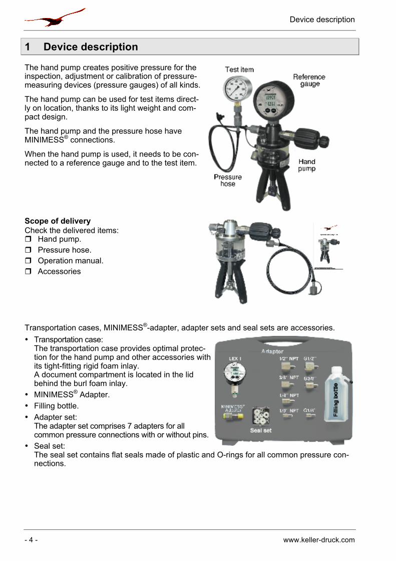
1 Device description The hand pump creates positive pressure for the inspection, adjustment or calibration of pressure-measuring devices (pressure gauges) of all kinds.
The hand pump can be used for test items direct-ly on location, thanks to its light weight and com-pact design.
The hand pump and the pressure hose have MINIMESS® connections.
When the hand pump is used, it needs to be con-nected to a reference gauge and to the test item.
Scope of delivery Check the delivered items: r Hand pump. r Pressure hose. r Operation manual. r Accessories Transportation cases, MINIMESS®-adapter, adapter sets and seal sets are accessories. • Transportation case:
The transportation case provides optimal protec-tion for the hand pump and other accessories with its tight-fitting rigid foam inlay. A document compartment is located in the lid behind the burl foam inlay.
• MINIMESS® Adapter. • Filling bottle. • Adapter set:
The adapter set comprises 7 adapters for all common pressure connections with or without pins.
• Seal set: The seal set contains flat seals made of plastic and O-rings for all common pressure con-nections.

Device description
Technical changes reserved - 5 -
Reference gauge: Various reference models from KELLER's product range can be used.
1.1 Intended use The HTP1 hand pump can only be used for generating pressure in low-volume measuring devices. The device is only designed for use with hydraulic oil or demineralised water, other media will result in damage to the hand pump. The hand pump may not be attached to external pressure sources.
WARNING! No safety component! The hand pump of the series HTP1 is not safety component in accordance with Directive 2006-42-EC (Machine Directive). Ä Never use the HTP1 as a safety component.
The operational safety of the device supplied is only guaranteed by intended use. The speci-fied limits (g § 9: "Technical data") may under no circumstances be exceeded.
CAUTION! Risk of injury or material damage! By connecting the HTP1, the measuring device is hydraulically connected to the hand pump. If the pressure relief valve is opened, a compressed medium can flow through the pressure hose into the hand pump's storage container. At sufficiently large volumes, the reservoir may overflow. Ä Never connect the HTP1 directly to the hydraulic system with large volumes (construc-
tion machines, etc.) or an aggressive medium (such as brake fluid).
Before ordering and installation, check that the hand pump is suitable for your applications.
1.2 Exclusion of liability We accept no liability for any damage or malfunctions resulting from incorrect installation, in-appropriate use of the device or failure to follow the instructions in this operating manual.

Safety instructions
- 6 - www.keller-druck.com
2 Safety instructions
Before you install the HTP1, read through this operating manual carefully. If the instruc-tions contained within it are not followed, in particular the safety guidelines, this could re-sult in danger for people, the environment, and the device and the system it is connected to.
The HTP1 corresponds with state-of-the-art technology. This concerns the accuracy, the op-erating mode and the safe operation of the device. In order to guarantee that the device operates safely, the operator must act competently and be conscious of safety issues. KELLER provides support for the use of its products either personally or via relevant litera-ture. The customer verifies that our product is fit for purpose based on our technical infor-mation. The customer performs customer- and application-specific tests to ensure that the product is suitable for the intended use. With this verification all hazards and risks are trans-ferred to our customers; our warranty is not valid.
Qualified personnel: The personnel who are charged for the installation and operation of the HTP1 must hold
a relevant qualification. This can be based on training or relevant tuition. The personnel must be aware of this operating manual and have access to it at all times.
General safety instructions: In all work, the existing national regulations for accident prevention and safety in the
workplace must be complied with. Any internal regulations of the operator must also be complied with, even if these are not mentioned in this manual.
Never use the hand pump together with an external pressure source. Do not attach an external pressure generator to the hand pump.
Do not use brake fluid or other aggressive media. Do not remove any attached components (test item, pressure hose, reference gauge)
when the hand pump is under pressure: Ä Open the pressure relief valve before removing any of the components. Do not use Teflon tape to seal the pressure connections. Surplus Teflon tape can enter
the hand pump and damage it. Ä Only use adapters and seals that are available as accessories. Non-pressurised storage: Only store the hand pump with the pressure relief valve open.
This ensures that no pressure can be built up by unintentional pumping movements. Avoid external force of all kinds towards the hand pump and its operating elements. Do not use the hand pump if it is damaged or defective.
Special safety instructions: Warnings that are specifically relevant to individual operating procedures or activities can be found at the beginning of the relevant sections of this operating manual.
Construction and function
Technical changes reserved - 7 -
3 Construction and function
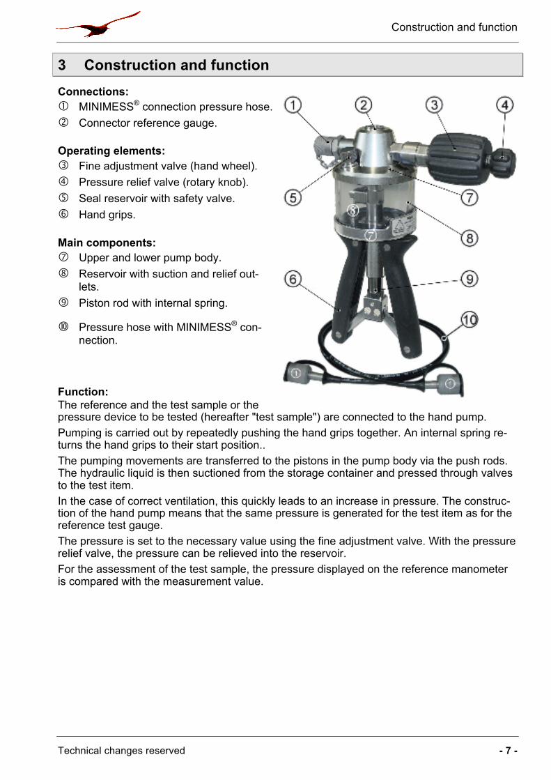
Connections: � MINIMESS® connection pressure hose. � Connector reference gauge.
Operating elements: � Fine adjustment valve (hand wheel). � Pressure relief valve (rotary knob). � Seal reservoir with safety valve. � Hand grips.
Main components: � Upper and lower pump body. � Reservoir with suction and relief out-
lets. � Piston rod with internal spring.
� Pressure hose with MINIMESS® con-nection.
Function: The reference and the test sample or the pressure device to be tested (hereafter "test sample") are connected to the hand pump. Pumping is carried out by repeatedly pushing the hand grips together. An internal spring re-turns the hand grips to their start position.. The pumping movements are transferred to the pistons in the pump body via the push rods. The hydraulic liquid is then suctioned from the storage container and pressed through valves to the test item. In the case of correct ventilation, this quickly leads to an increase in pressure. The construc-tion of the hand pump means that the same pressure is generated for the test item as for the reference test gauge. The pressure is set to the necessary value using the fine adjustment valve. With the pressure relief valve, the pressure can be relieved into the reservoir. For the assessment of the test sample, the pressure displayed on the reference manometer is compared with the measurement value.

Commissioning with ventilation
- 8 - www.keller-druck.com
3.1 Important notes on pressure fluctuations
It is completely normal that the pressure is not constant from the start. In the event of changes to the pressure in the measurement device, it always lasts a few minutes until the pressure stabilises.
This is influenced by a variety of factors. The most important influence factors are: • Poor ventilation:
If there is still air in the measurement device, the pressure build-up lasts significantly longer. Moreover, there is a fall-off in pressure over a limited period due to diffusion pro-cesses.
• Mechanical characteristics of the pressure hose: Bending or rolling up the pressure hose causes a reduction in the volume and thus leads to an increase in pressure. At high pressure, the pressure hose extends. Furthermore, enclosed air can be diffused through the pressure hose. In both cases, a drop in pressure results.
• Temperature influence: Temperature changes lead to a change in volume in the measurement device and there-fore to changes in pressure. The smaller the volume is, the greater the change in pres-sure.
• Settling times of reference and test sample: Observe the required waiting times after the reference and test sample have been switched on. More information on this can be found in the corresponding operating man-ual.
4 Commissioning with ventilation In order for the hand pump to be operated, it is vital that its connections with the reference gauge and the test item are pressure-resistant. Furthermore, for the best measurement procedure possible, sufficient and correct ventilation of the measurement device is required. Only then can you reduce the pressure fluctuations (g § 3.1) to a minimum.
CAUTION! Material damage! The test sample, the adapter and the seal must be free from impurities. If impurities enter the hand pump through the pressure hose, this may be damaged.
Maximum torque of the pressure connections! Reference: 15 Nm Test item: 15 Nm
Carry out the following steps*1 for the commissioning and ventilation of the hand pump. For this, note also the warnings in section § 5.1 "Generating pressure". Ä Fill the storage container to approximately two-thirds capacity with the required hydraulic
fluid. Ä Open the pressure relief valve by turning counter-clockwise.
Ä Turn the reference manometer with matching seal in the hand pump's connection (G ¼). IMPORTANT! Do not tighten the reference yet!
Ä Carefully pump until the hydraulic liquid escapes at the connection and the piston system has been ventilated.
* The first steps up to "Tightening of the reference" are only required for the first commissioning or during re-moval of the reference.

Handling
Technical changes reserved - 9 -
Ä Only then should you tighten the reference. Ä Pump 5…10 times to ventilate the ventilation channels. Ä Turn the pressure relief valve counter-clockwise until it is firmly closed. Ä Connect the pressure hose to the hand pump's MINIMESS® connection, and tighten the
connection. Ä Tightly screw the MINIMESS® adapter on the pressure hose. Ä Select the suitable adapters and seals for the test item's connection. Ä Screw the adapter for the test sample onto the MINIMESS® adapter. Ä Turn the test sample with seal in the adapter.
IMPORTANT! Do not yet tighten the test item! Ä Now pump until the hydraulic liquid escapes at the test sample's connection. The pres-
sure hose and the test sample connection are now ventilated.
CAUTION! Demineralised water! During the quality inspection of the HTP1, a functional test is carried out with demineral-ised water. The reservoir may therefore contain residues of this liquid. Ä Check the compatibility with your application and remove the residue using appropri-
ate measures (e.g. rinsing out with the hydraulic liquid).
5 Handling
Adhere to the following safety instructions when operating the hand pump:
CAUTION! Crushing hazard! During the pumping procedure ensure that fingers or other body parts are kept away from the area between the hand grips and the piston rod.
CAUTION! Material damage to valve stop! If put under too much strain the stop and the hand pump will be damaged. Ä Only continue to tighten the valves (the fine adjustment and pressure relief valves) by
hand, once the stop has been reached.
Before creating pressure consider: Before you create pressure with the hand pump you should check for the following require-ments: r The reference gauge is connected to the hand pump. r The test item is joined to the pressure hose with the correct adapters and seals. r All pressure connections are correctly in place, so that they resist pressure. r The hand pump, the pressure hose and the test sample have been properly ventilated
(g § 4).

Handling
- 10 - www.keller-druck.com
5.1 Generating pressure After the commissioning with ventilation, pressure can be created with the hand pump. With increasing back-pressure in the system, the pumping process becomes more and more diffi-cult.
WARNING! There is a risk of injury if the maximum pressure is exceeded! Note the maximum permitted pressures of the individual components in the measure-ment device. If the limit values are exceeded, it may lead to material damage and inju-ries. ÄDo not continue to pump under any circumstances if the maximum permitted pressure has been reached or an exceeded measuring range is displayed.
CAUTION! Material damage to test item! Adhere to the maximum pressure of the test item! Only create an admission pressure with the hand grips that is lesser than the necessary test-ing pressure. Following this carefully increase the pressure using the fine adjustment valve.
Notes on operation Please observe the following notes concerning the operation of the hand pump: • Ensure that no air is suctioned during the pumping
process. Ø To ensure that this does not occur, hold the hand
pump at a slight angle so that the suction nozzles are always surrounded by hydraulic liquid.
• Ensure that there is sufficient hydraulic liquid in the reservoir.
Ø If necessary, refill the hydraulic liquid. This must also be ensured during depressurisation (g).
• For small hydraulic volumes and well-ventilated systems, a higher pressure is already built up with a few movements of the pump.
Ø Ensure that the maximum permitted pressure is not exceeded.
• From approximately 400...500 bar, a lot of strength is required for pumping from the initial position of the handles.
Ø Increase the pressure using the fine adjustment valve and note the following tip.
TIP! At high pressures, open the handle only lightly. The handles can be compressed more easily the further the handles are closed. In this way, you can create high pressures more easily and meter the pressure better. Ä The higher the pressure is, the less you should open the handles. In the event of high
pressures, avoid the initial position of the handles.
+p
Handling
Technical changes reserved - 11 -
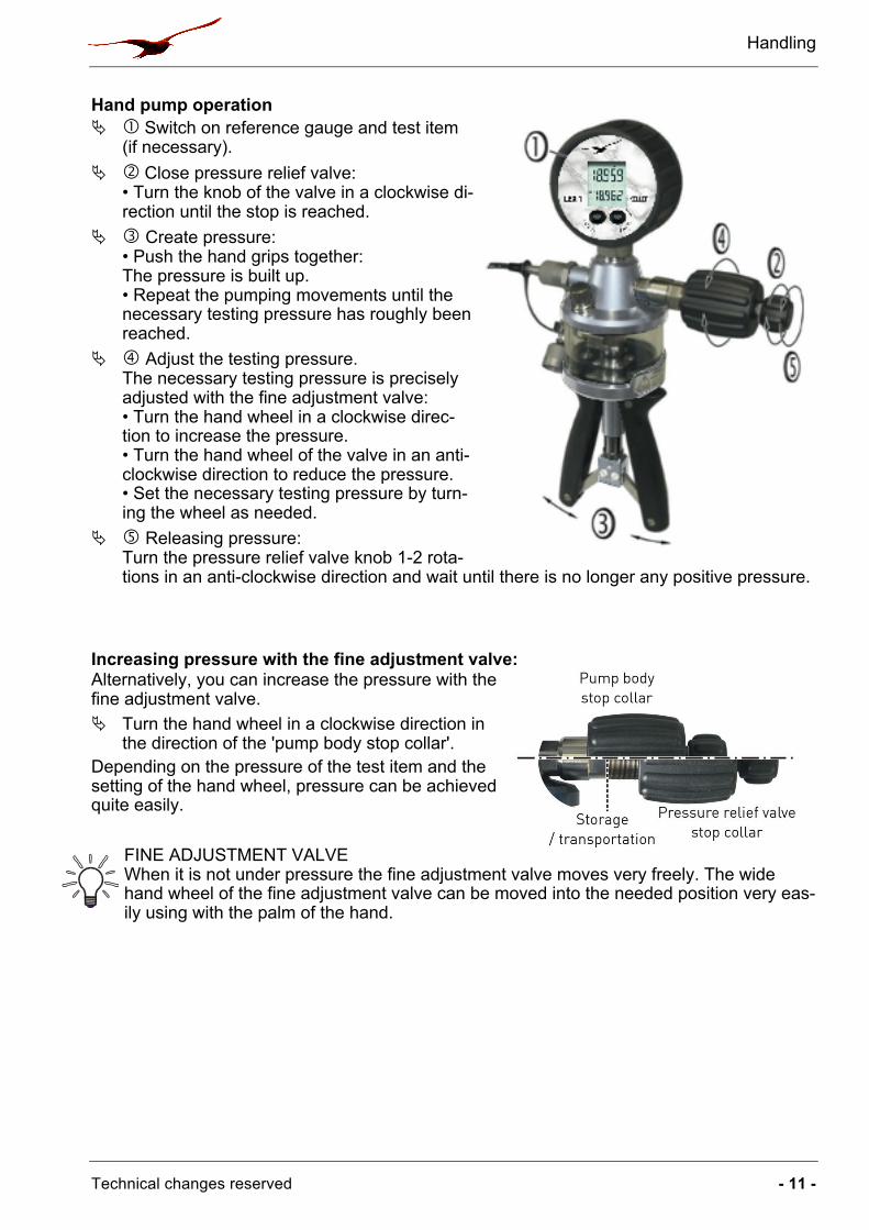
Hand pump operation Ä � Switch on reference gauge and test item
(if necessary). Ä � Close pressure relief valve:
• Turn the knob of the valve in a clockwise di-rection until the stop is reached.
Ä � Create pressure: • Push the hand grips together: The pressure is built up. • Repeat the pumping movements until the necessary testing pressure has roughly been reached.
Ä � Adjust the testing pressure. The necessary testing pressure is precisely adjusted with the fine adjustment valve: • Turn the hand wheel in a clockwise direc-tion to increase the pressure. • Turn the hand wheel of the valve in an anti-clockwise direction to reduce the pressure. • Set the necessary testing pressure by turn-ing the wheel as needed.
Ä � Releasing pressure: Turn the pressure relief valve knob 1-2 rota-tions in an anti-clockwise direction and wait until there is no longer any positive pressure.
Increasing pressure with the fine adjustment valve: Alternatively, you can increase the pressure with the fine adjustment valve. Ä Turn the hand wheel in a clockwise direction in
the direction of the 'pump body stop collar'. Depending on the pressure of the test item and the setting of the hand wheel, pressure can be achieved quite easily.
FINE ADJUSTMENT VALVE When it is not under pressure the fine adjustment valve moves very freely. The wide hand wheel of the fine adjustment valve can be moved into the needed position very eas-ily using with the palm of the hand.
Handling
- 12 - www.keller-druck.com
5.2 Pressure measurements For adjustments, calibrations or an inspection of accuracy, it is vital that the test item and the reference have the same pressure. The pressure needed for the test points is built up and adjusted with the hand pump (g § 5.1).
Wait for pressure stabilisation! After changes in the pressure, it takes a few minutes for the pressure in the measure-ment device to stabilise ((g § 3.1). Ä Wait approximately 3…5 min before you begin taking measurements.
The necessary procedures for measuring pressure are configured by the operator.
Carrying out the pressure measurements: • Carry out the necessary tests and measurements. • Document your results.
5.3 Releasing pressure Once the pressure measurements have been completed, the positive pressure in the hand pump, the test item and in the pressure hose need to be brought into balance.
CAUTION! Risk of injury through excessive pressure! Do not remove any connected components (test item, pressure hose, reference gauge) if the hand pump is under pressure. Ä Open the pressure relief valve before removing any of the components.
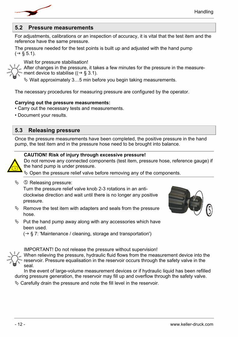
Ä � Releasing pressure: Turn the pressure relief valve knob 2-3 rotations in an anti-clockwise direction and wait until there is no longer any positive pressure.
Ä Remove the test item with adapters and seals from the pressure hose.
Ä Put the hand pump away along with any accessories which have been used. (g § 7: 'Maintenance / cleaning, storage and transportation')
IMPORTANT! Do not release the pressure without supervision! When relieving the pressure, hydraulic fluid flows from the measurement device into the reservoir. Pressure equalisation in the reservoir occurs through the safety valve in the seal. In the event of large-volume measurement devices or if hydraulic liquid has been refilled
during pressure generation, the reservoir may fill up and overflow through the safety valve. Ä Carefully drain the pressure and note the fill level in the reservoir.
+p
Problems
Technical changes reserved - 13 -
6 Problems
CAUTION! Material damage! The hand pump cannot be repaired by the operator! In the case of a defect, the appli-ance must be sent back to the manufacturer for repair. Ä Never open up the hand pump and / or carry out any repairs yourself.
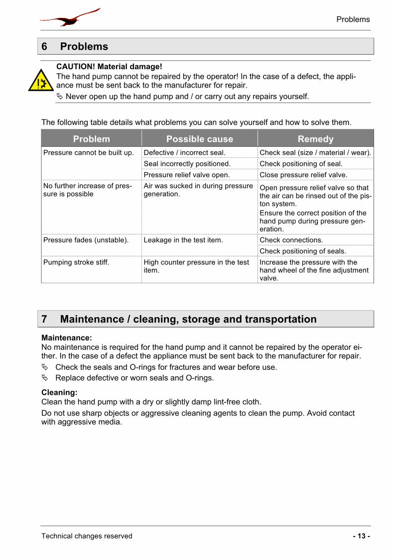
The following table details what problems you can solve yourself and how to solve them.
7 Maintenance / cleaning, storage and transportation Maintenance: No maintenance is required for the hand pump and it cannot be repaired by the operator ei-ther. In the case of a defect the appliance must be sent back to the manufacturer for repair. Ä Check the seals and O-rings for fractures and wear before use. Ä Replace defective or worn seals and O-rings.
Cleaning: Clean the hand pump with a dry or slightly damp lint-free cloth. Do not use sharp objects or aggressive cleaning agents to clean the pump. Avoid contact with aggressive media.
Problem Possible cause Remedy Pressure cannot be built up. Defective / incorrect seal. Check seal (size / material / wear).
Seal incorrectly positioned. Check positioning of seal. Pressure relief valve open. Close pressure relief valve.
No further increase of pres-sure is possible
Air was sucked in during pressure generation.
Open pressure relief valve so that the air can be rinsed out of the pis-ton system. Ensure the correct position of the hand pump during pressure gen-eration.
Pressure fades (unstable). Leakage in the test item. Check connections. Check positioning of seals.
Pumping stroke stiff. High counter pressure in the test item.
Increase the pressure with the hand wheel of the fine adjustment valve.

Disposal
- 14 - www.keller-druck.com
Storage and transportation: For storage and transportation we recommend our transportation case, which is available as an accessory. The tight-fitting rigid foam inlay offers optimum protection for the hand pump with pressure hose and accessories.
REFERENCE GAUGE The common reference models fit into the gaps in the transportation case and do not need to be removed.
Before storage, we recommend that you consider the following points: r Clean the hand pump and the accessories. r Turn the fine adjustment valve in a clockwise direction
until the thread is no longer visible (g illustration). r Open the pressure relief valve.
IMPORTANT! Do not store under pressure! Only store the hand pump with the pressure relief valve open. This ensures that no pressure can be built up by unintentional pumping move-
ments.
8 Disposal The hand pump consists of various different materials. It should not be disposed of with household waste. Ä Take the hand pump to your local recycling plant
or
Ä send the hand pump back to your supplier or to KELLER.

Technical data
Technical changes reserved - 15 -
9 Technical data
Type HTP1 Pump with hose Pressure range: - Positive pressure 700 bar Medium: Hydraulic oil
Demineralised water Connection: - Reference G ¼ - Pressure hose MINIMESS® 1620 - Test item Pressure hose (1 m) with MINIMESS® 1620
or with MINIMESS®-adapter 1620 to G ¼
Dimensions: ~ 255 x 225 x 85 mm Weight: ~ 1,7 kg
Accessories MINIMESS®-adapter MINIMESS® 1620 auf G ¼
Illustration (example):
Complete set with reference LEX1
Adapter set: G1/8’’, G3/8’’, G1/2’’ , 1/8’’ NPT,
3/8’’ NPT, 1/4’’ NPT, 1/2’’ NPT Seal set: Flat seals made of plastic
and O-rings Transportation case: - Lid Burl foam with document
compartment - Main compartment Tight-fitting rigid foam inlay
for pump and accessories r
- Dimensions ~ 450 x 370 x 125 mm - Weight with pump and accessories
~ 4,8 kg
Pressure hose: Replacement pressure hose with
seals Consumables: Demineralised water, Hydraulic oil