Hydraulic Design of Depressed Curb-Opening...
20
Part III DEPRESSED CURB-OPENING.' INLETS Hydraulic Design of Depressed Curb-Opening Inlets WILLIAM J. BAUER and DAR-CHENG WOO Respectively, Consulting Engineer, Chicago, Ill., and Hydraulic Engineer, U. S. Bureau of Public Roads, Washington, D. C. New hydraulic design curves for depressed curb-opening inlets have been developed from new experimental data. A general description of the research and of the development of these curves and their application is presented. These curves cover a considerable range of practical conditions and also allow di- rect comparison of the effect of size of depression to the effi- ciency of the inlet. The sump condition is included in this paper. The condition of the submerged inlet is not covered, nor is the determination of design discharge. The term "sump condition" in this paper refers to the condition that the inlet is located at the low point of a sag vertical curve . Nomenclature The following symbols used throughout this paper are defined where they first ap- pear, but for easy reference are gathered here. a= Vertical distance of depression in plane of curb face measured from intersection of normal street surface and curb face (in.); d = Water depth of uniform gutter flow at curb face (ft); dmax = Maximum gutter water depth (ft); dw = Water depth (ft) at distance W from the curb face = Sx(T-W); Fw = Froude number based on depth and velocity of uniform gutter flow at distance W from the curb face; hm = Minimum curb opening height for free fall flow (ft); H = Total head over crest of curb opening at center of inlet; K = Empirical coefficient of transverse acceleration; Li = Curb-opening inlet length (ft); n = Roughness coefficient in the modified Manning's formula for triangular gutter flow (6) (Eq. 9); q = ModifTed unit discharge (cu ft per sec per ft); Q = Gutter flow ( cfs); Qi = The portion of gutter flow intercepted by curb-opening inlet ( cfs); Paper sponsored by Committee on Surf ace Drainage of Highways . 61
-
Upload
truonghanh -
Category
Documents
-
view
216 -
download
1
Transcript of Hydraulic Design of Depressed Curb-Opening...
Part III
DEPRESSED CURB-OPENING.' INLETS
Hydraulic Design of Depressed Curb-Opening Inlets WILLIAM J. BAUER and DAR-CHENG WOO
Respectively, Consulting Engineer, Chicago, Ill., and Hydraulic Engineer, U. S. Bureau of Public Roads, Washington, D. C.
New hydraulic design curves for depressed curb-opening inlets have been developed from new experimental data. A general description of the research and of the development of these curves and their application is presented. These curves cover a considerable range of practical conditions and also allow direct comparison of the effect of size of depression to the efficiency of the inlet. The sump condition is included in this paper. The condition of the submerged inlet is not covered, nor is the determination of design discharge. The term "sump condition" in this paper refers to the condition that the inlet is located at the low point of a sag vertical curve .
Nomenclature
The following symbols used throughout this paper are defined where they first appear, but for easy reference are gathered here.
a= Vertical distance of depression in plane of curb face measured from intersection of normal street surface and curb face (in.);
d = Water depth of uniform gutter flow at curb face (ft); dmax = Maximum gutter water depth (ft);
dw = Water depth (ft) at distance W from the curb face = Sx(T-W); Fw = Froude number based on depth and velocity of uniform gutter flow at distance
W from the curb face; hm = Minimum curb opening height for free fall flow (ft);
H = Total head over crest of curb opening at center of inlet; K = Empirical coefficient of transverse acceleration;
Li = Curb-opening inlet length (ft); n = Roughness coefficient in the modified Manning's formula for triangular gutter
flow (6) (Eq. 9); q = ModifTed unit discharge (cu ft per sec per ft); Q = Gutter flow ( cfs);
Qi = The portion of gutter flow intercepted by curb-opening inlet ( cfs);
Paper sponsored by Committee on Surface Drainage of Highways .
61
62
Sx (CROSS SLOPE)
~NGITUDINAL SLOPE) STflEET SIDE
~~-~~~~-~~~~,--
CARRY OVER
Q - Qi - ~------71
I w
GUTTER FLOW,Q
Fw(FROUDE NO - AT THIS PT)
CURB..,_
Oj(INTERCEPTED FLOW)
I I
. ·' Lj
(LENGTH OF OPENING)
PLAN
Graphical definition of symbols .
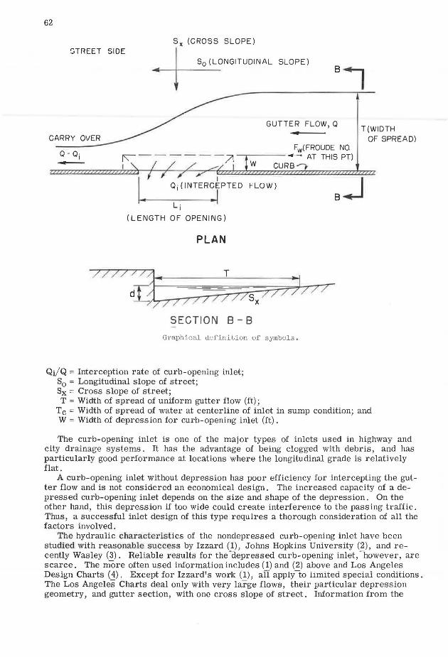
Qi/Q = Interception rate of curb-opening inlet; S0 = Longitudinal slope of street; Sx = Cross slope of street; T = Width of spread of uniform gutter flow (ft);
T(WIOTH OF SPREAD)
Tc = Width of spread of water at centerline of inlet in sump condition; and W = Width of depression for curb-opening inlet (ft).
The curb-opening inlet is one of the major types of inlets used in highway and city drainage systems . It has the advantage of being clogged with debris, and has particularly good performance at locations where the longitudinal grade is relatively flat.
A curb-opening inlet without depression has poor efficiency for intercepting the gutter flow and is not considered an economical design. The increased capacity of a depressed curb-opening inlet depends on the size and shape of the depression. On the other hand, this depression if too wide could create interference to the passing traffic. Thus, a successful inlet design of this type requires a thorough consideration of all the factors involved.
The hydraulic chru:acteristics of the nonclepressed curb-opening inlet have been studied with reasonable success by Izzard (1), Johns Hopkins University (2), and recently Wasley (3). Reliable results for the -depressed curb-opening inlet, -however, are scarce. The more often used information includes (1) and (2) above and Los Angeles Design Charts (4). Except for Izzard's work (1), aiI apply-to limited special conditions. The Los Angeles Charts deal only with very large flows, their particular depression geometry, and gutter section, with one cross slope of street. Information from the
investigation reported here is needed to evaluate many condition combinations not previously measured.
63
Pavement and gutter runoff during rain storms is a rather complicated problem. A steady uniform gutter flow is assumed, for this study. Design gutter discharge determination is not within the scope of this study.
RESEARCH
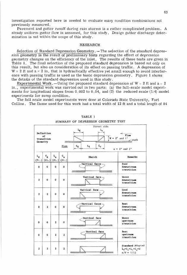
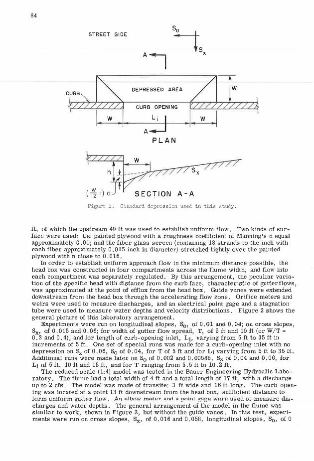
Selection of standard Depression Geometry. -The selection of the standard depression geometry is the result of preliminary tests regarding the effect of depression geometry changes on the efficiency of the inlet. The results of these tests are given in Table 1. The final selection of the proposed standard depression is based not only on this result, but also on consideration of its effect on passing traffic. A depression of W = 2 ft and a = 2 in. that is hydraulically effective yet small enough to avoid interference with passing traffic is used as the basic depression geometry. Figure 1 shows the details of the standard depression used in this study.
Experimental Work. - Using the proposed standard depression of W = 2 ft and a = 2 in. , experimental work was carried out in two parts: (a) the full-scale model experiments for longitudinal slopes from 0.002 to 0.04, and (2) the reduced scale (1:4) model experiments for sump condition.
The full scale model experiments were done at Colorado State University, Fort Collins. The flume used for this work had a total width of 12 ft and a total length of 84
Definition of
Transition Geometry
Ld Cd
(Ft .) (l.'C . >.
0 0
2 0
2
0 2
0 0
0 0
2 2
TABLE 1
SUMMARY OF DEPRESSION GEOMETRY TEST
St r eet side
a = 211 and l 11
L c Sutch R.,..rlta u u
(Ft . ) (Ft. )
Vertical faces Poor 0 0
IZZZZ Z ZZ21Z j I zzzzzzzzz
downs tre.a. transition
Vertical face Worst 0 0
!ilill/U?il/.[\ tan dOWIIB treut transition
?e?Z?
Vertical
face t::!P<ZZ Good
0 0
' ZZZZZZ!~ d·ownetream transition
G Vertical
facetzzmzz
Beat
0 0 .. .,, .. :L .. z,
downstream transition
...-Verticlll face. Worst
2 0 ' ·1 L'.l upatream. transition
r.o '"'"
S Ver tical face Best 2 2 ~
upatreaa
tt? lt? transition
f----
I~, Standard Adopted
2 ~"'""' Ld=Cd=Lu=C0 =W n a/W = 1/ 12
64
STREET SIDE
DEPRESSED AREA
CURB OPENING
A+-1 PLAN
( ~ =) SECTION A-A
Figure 1. Standard depression used in this study .
ft, of which the upstream 40 ft was used to establish uniform flow. Two kinds of surface were used: the painted plywood with a roughness coefficient of Manning's n equal approximately 0.01; and the fiber glass screen (containing 18 strands to the inch with each fiber approximately 0. 015 inch in diameter) stretched tightly over the painted plywood with n close to 0 . 016.
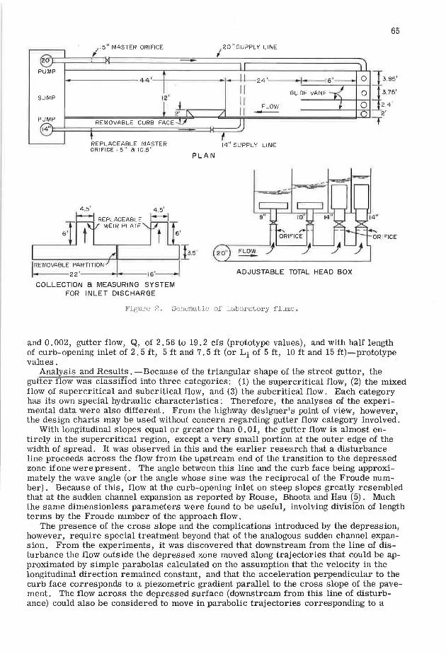
In order to establish uniform approach flow in the minimum distance possible, the head box was constructed in four compartments across the flume width, and flow into each compartment was separately regulated. By this arrangement, the peculiar variation of the specific head with distance from the curb face, characteristic of gutter flows, was approximated at the point of efflux from the head box. Guide vanes were extended downstream from the head box through the accelerating flow zone. Orifice meters and weirs were used to measure discharges, and an electrical point gage and a stagnation tube were used to measure water depths and velocity distributions. Figure 2 shows the general picture of this laboratory arrangement.
Experiments were run on longitudinal slopes, S0 , of 0.01and0.04; on cross slopes, Sx, of 0.015 and 0.06; for width of gutter flow spread, T, of 5 ft and 10 ft (or W/T = 0. 2 and 0. 4); and for length of curb-opening inlet, Lb varying from 5 ft to 3 5 ft in increments of 5 ft. One set of special runs was made for a curb-opening inlet with no depression on 8x of 0. 06, S0 of 0. 04, for T of 5 ft and for Li varying from 5 ft to 35 ft. Additional runs were made later on S0 of 0.002 and 0.00585, Sx of 0.04 and 0.06, for Li of 5 ft, 10 ft and 15 ft, and for T ranging from 5. 5 ft to 10. 2 ft.
The reduced scale (1:4) model was tested in the Bauer Engineering Hydraulic Laboratory. The flume had a total width of 4 ft and a total length of 17 ft, with a discharge up to 2 cfs. The model was made of transite: 3 ft wide and 16 ft long. The curb opening was located at a point 13 ft downstream from the head box, sufficient distance to form uniform giitter flow. An elbo¥T meter <tnd a point e;agP. wP.rP. used to measure discharges and water depths . The general arrangement of the model in the flume was similar to work, shown in Figure 2, but without the guide vanes. In this test, experiments were run on cross slopes, Sx, of 0.016 and 0.058, longitudinal slopes, S0 , of 0
65
115" MASTER ORIFICE
120" SUPPLY LINE
20~· -L---T'---u------------,,,,----<--------------~
PUMP - ------44 ._,__ ____ __...,..,, ... ,e------<1H-1- 24 ·-----i·- 16'- 0 ]3.85'
11 GUIDE VANE 0 J 3.75' SUMP
11 FLOW 0 _J_24' II -- ---~---=-< 2·
12'
PUMP
14"J:==:===i=========:::::::;;;;;::::=H::::::::=~ t
REMOVABLE CURB FACE
REPLACEABLE MASTER ORIFICE: 5" 81 10_5"
4 .5 ' 4 .5'
I REPLACEABLE r--i WEIR PLATE
'----------+-+----------l
!REMOVABLE PARTITION I I
. • 22'---~-15·-
COLLECTION a MEASURING SYSTEM FOR INLET DISCHARGE
14" SUPPLY LINE
PLAN
} .5' 20"
ADJUSTABLE TOTAL HEAD BOX
Figure 2. Schematic of laboratory flume .
+
and 0.002, gutter flow, Q, of 2.56 to 19.2 cfs (prototype values), and with half length of curb-opening inlet of 2. 5 ft, 5 ft and 7. 5 ft (or Li of 5 ft, 10 ft and 15 ft)-prototype values.
Analysis and Results. -Because of the triangular shape of the street gutter, the gutter flow was classified into three categories: (1) the supercritical flow, (2) the mixed flow of supercritical and subcritical flow, and (3) the subcritical flow. Each category has its own special hydraulic characteristics: Therefore, the analyses of the experimental data were also different. From the highway designer's point of view, however, the design charts may be used without concern regarding gutter flow category involved.
With longitudinal slopes equal or greater than 0. 01, the gutter flow is almost entirely in the supercritical region, except a very small portion at the outer edge of the width of spread. It was observed in this and the earlier research that a disturbance line proceeds across the flow from the upstream end of the transition to the depressed zone if one were present. The angle between this line and the curb face being approximately the wave angle (or the angle whose sine was the reciprocal of the Froude number). Because of this, flow at the curb-opening inlet on steep slopes greatly resembled that at the sudden channel expansion as reported by Rouse, Bhoota and Hsu (5). Much the same dimensionless parameters were found to be useful, involving divisfun of length terms by the Froude number of the approach flow.
The presence of the cross slope and the complications introduced by the depression, however, require special treatment beyond that of the analogous sudden channel expansion. From the experiments, it was discovered that downstream from the line of disturbance the flow outside the depressed zone moved along trajectories that could be approximated by simple parabolas calculated on the assumption that the velocity in the longitudinal direction remained constant, and that the acceleration perpendicular to the curb face corresponds to a piezometric gradient parallel to the cross slope of the pavement. The flow across the depressed surface (downstream from this line of disturbance) could also be considered to move in parabolic trajectories corresponding to a
66
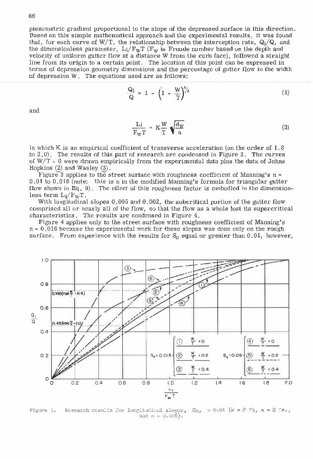
piezometric gradient proportional to the slope of the depressed surface in this direction. Based on this simple mathematical approach and the experimental results, it was found that, for each curve of W /T, the relationship between the interception rate, QJQ, and the dimensionless parameter, Li/FwT (Fw is Froude number based on the depth and velocity of uniform gutter flow at a distance W from the curb face), followed a straight line from its origin to a certain point. The location of this point can be expressed in terms of depression geometry dimensions and the percentage of gutter flow in the width of depression W. The equations used are as follows:
(1)
and
(2)
in which K is an empirical coefficient of transverse acceleration (on the order of 1. 8 to 2. 0). The results of this part of research are condensed in Figure 3. The curves of W /T = 0 were drawn empirically from the experimental data plus the data of Johns Hopkins (2) and Wasley (3).
Figure- 3 applies to the street surface with roughness coefficient of Manning's n = 0.01 to 0.016 (note: this is n in the modified Manning's formula for triangular gutter flow shown in Eq. 9). The effect of this roughness factor is embodied in the dimensionless term Li/FwT.
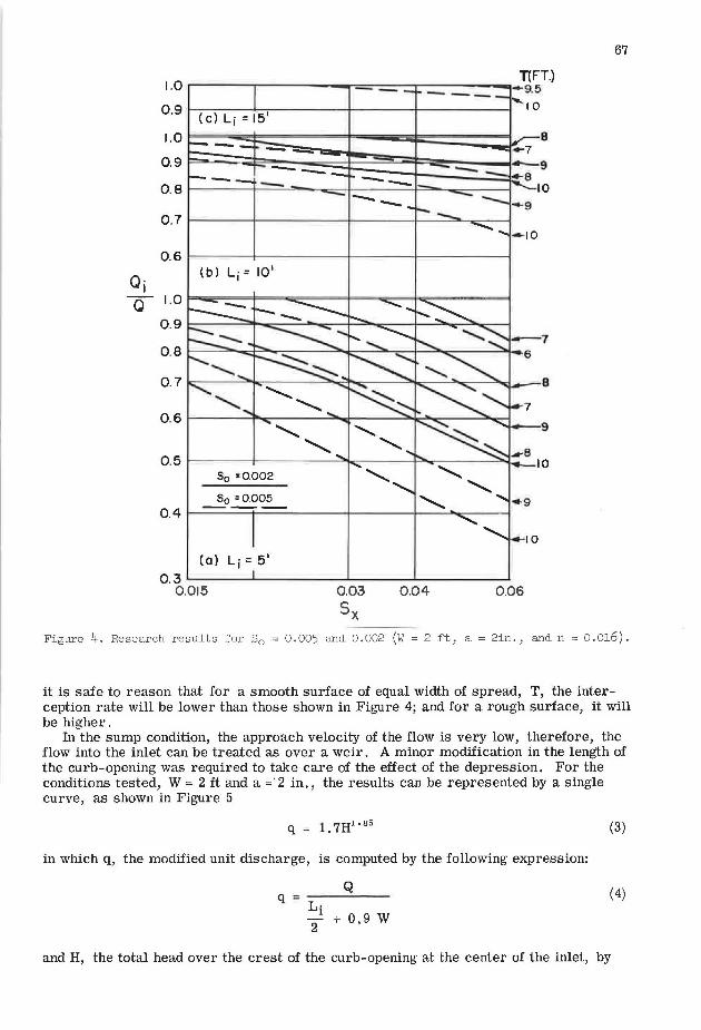
With longitudinal slopes 0. 005 and 0. 002, the subcritical portion of the gutter flow comprised all or nearly all of the flow, so that the flow as a whole lost its supercritical characteristics. The results are condensed in Figure 4.
Figure 4 applies only to the street surface with roughness coefficient of Manning's n = 0. 016 because the experimental work for these slopes was done only on the rough surface. From experience with the results for S0 equal or greater than 0. 01, however,
Q· I a
0 . 2 t--'-'----j;''--7,0V,,.-'---+----+---+ s, = 0 015 l: ~ : : ' @ f =0.4 ----- I
@) f = O
s,=o,os ~ __ y_=_o.:.2_
® f =0.4 -------0.2 0.4 0.6 0.8 1.2 1.4 1.6 18 2.0
Figure 3 , Research results for longitudinal slopes, 80 , ~ 0.01 (W = 2 ft, a= 2 in., and n = 0 .016).
Q· I Q
.----..-------==-=-----.----- T(FT.) -- -9.5 ---1.0
0.9 t-----..,__,--------1-----il-------1'10 (c) Lj = 15'
1.0 8
0.9
0.8 --0.7
0.6 (b) Li= 10'
1.0
0.9
0.8
0.1
0.6
0.5 So =0.002
So =0.005 0.4 -----
(al Lj = 5'
0.3 O.Ol5 0.03
Sx 0.04 0.06
67
Figure 4. Research results for 30 = 0.005 and 0.002 (W = 2 ft, a= 2in., and n = O.Ol6).
it is safe to reason that for a smooth surface of equal width of spread, T, the interception rate will be lower than those shown in Figure 4; and for a rough surface, it will be higher.
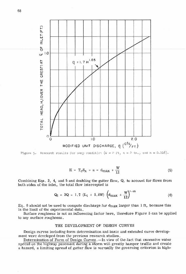
In the sump condition, the approach velocity of the flow is very low, therefore, the flow into the inlet can be treated as over a weir. A minor modification in the length of the curb-opening was required to take care of the effect of the depression. For the conditions tested, W = 2 ft and a= 2 in., the results can be represented by a single curve, as shown in Figure 5
q = 1. 7H1.a5
in which q, the modified unit discharge, is computed by the following expression:
Q q ::----
Li 2 + 0.9 w
(3)
( 4)
and H, the total head over the crest of the curb-opening at the center of the inlet, by
68
~ LL
1-w _J
z LL 0 ~ 1.0
1-<l
I-CJ)
w a:: 0
w I l-
a:: w > 0
I
0 <l w I
_J
<l lo I-
0
v v v
_/
v
q =1. 7 Hl.85 v v ~
v v
/ vv J
v I I 0 1.0 2.0
MODI Fl ED UN IT DISCHARGE, q ( cfs; FT.)
Figure 5. Research results for sump condition (W = 2 ft, a= 2 in., and n = 0.016).
w H = T c8x + a = dmax + 12 (5)
Combining Eqs. 3, 4, and 5 and doubling the gutter flow, Q, to account for flows from both sides of the inlet, the total flow intercepted is
( w)1.as Qi = 2Q = 1. 7 (Li + 1.8W) dmax +
12 (6)
Eq. 6 should not be used to compute discharge for dmax larger than 1 ft, because this is the limit of the experimental data.
Surface roughness is not an influencing factor here, therefore Figure 5 can be applied to any surface roughness .
THE DEVELOPMENT OF DESIGN CURVES
Design curves including form determination and basic and extended curve development were developed from the previous research studies.
Determination of Form of Design Curves. -In view of the fact that excessive water spread on the highway pavement during a storm will greatly hamper traffic and create a hazard, a limiting spread of gutter flow is normally the governing criterion in high-
69
way surface drainage design. Therefore, this gutter flow spread, T, the cross slope, Sx, the longitudinal slope, S0 , and the length of the curb-opening, Li, form the basic design curve parameters. The effect of roughness was tested and found to be relatively insignificant for the proper design of curb-opening inlets, as long as the same roughness is assumed in determining the width of spread and the inlet performance.
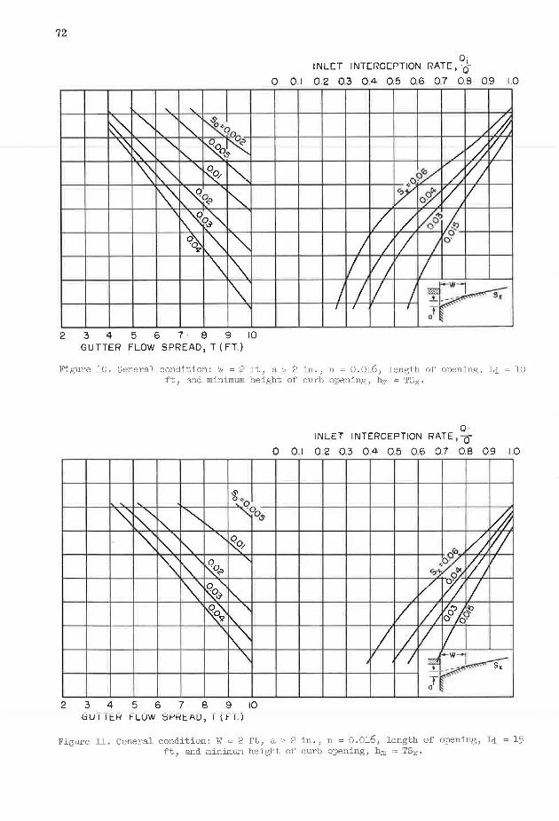
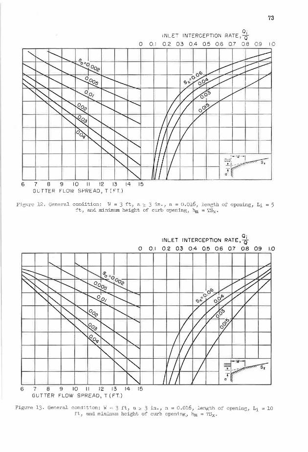
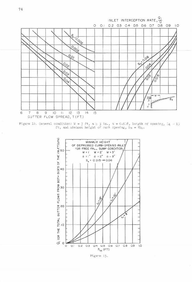
Basic Design Curves. -From the original research results, design curves for the basic depression geometry of W = 2 ft and a = 2 in. were derived. The range of the spread of gutter flow, T = 2W to 5W, was selected from practical consideration, as were the ranges of other conditions. These curves were condensed into five Figures: (1) Figure 10 for Li= 5 ft, W = 2 ft, a= 2 in.; (2) Figure 11 for Li= 10 ft, W = 2 ft, a = 2 in. ; (3) Figure 12 for Li = 15 ft, W = 2 ft, a = 2 in.; ( 4) Figure 16, showing the minimum height of curb opening required to clear the water surface of flow into the inlet under sump conditions, was derived from the water surface profiles measured at the plane of the curb opening during the sump tests and (5) Figure 18 for W = 2 ft, a = 2 ft under sump conditions. For Figures 10 to 12, and requirement for the minimum curb-opening height for free fall flow is specified (hm = TSx) . Although no actual water surface profile measurements were taken during these tests, these criteria were derived from a few detailed measurements of the flow characteristics at the inlet area and from general knowledge of the previous studies on this subject.
Extended Design Curves. -Using Froude's law of similitude relationships, two more sets of design curves were derived for depressions of W = 3 ft and a= 3 in., and of W = 1 ft and a= 1 in., respectively. '
Before this method of basic information extension was applied, the state of flow under the new conditions was checked thoroughly to verify that the Reynolds number was sufficiently large so that differences in viscous effects could be ignored. All flows were found to be in the turbulent region except a very small part of the W = 1 ft and a= 1 in. curves. All curves are, however, believed to give conservative design values.
It should be pointed out that because Eq. 3 is not dimensionally homogeneous, it cannot be applied directly to the depressions of W = 1 ft and W = 3 in. under sump conditions. By using Froude's law of similitude and the experimental results, it was found that for W = 1 ft and a = 1 in. :
( w)1.1a Qi = 2Q = 2 (Li + 2. 4 W) dmax +
12 (7)
and for W = 3 ft and a = 3 in. :
( w)1.as Qi= 2Q = 1.475 (Li + 1.8 W) dmax +
12 (8)
Eqs. 7 and 8 should not be used to compute dmax discharges larger than 1 ft. · Design Curves. -The new hydraulic design curves for curb-opening inlets with the
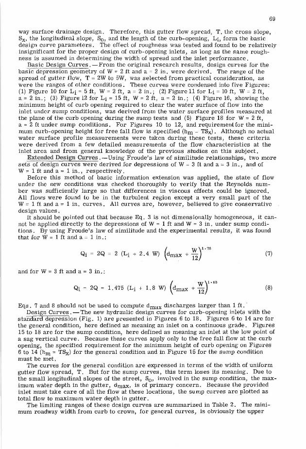
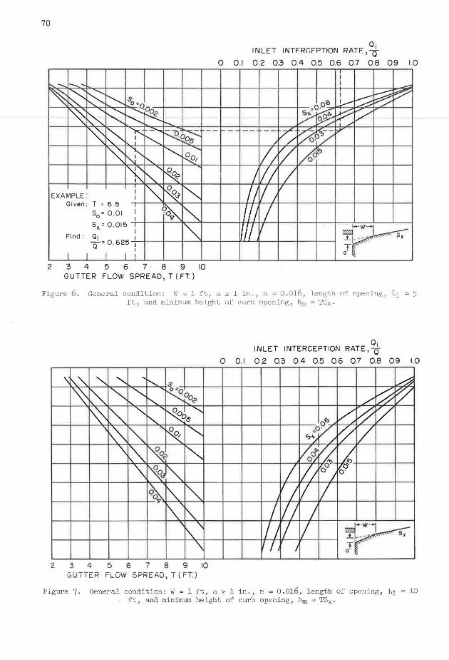
standard depression (Fig. 1) are presented in Figures 6 to 18. Figures 6 to 14 are for the general condition, here defined as meaning an inlet on a continuous grade. Figures 15 to 18 are for the sump condition, here defined as meaning an inlet at the low point of a sag vertical curve. Because these curves apply only to the free fall flow at the curb opening, the specified requirement for the minimum height of curb opening on Figures 6 to 14 (hm = TSx) for the general condition and in Figure 15 for the sump condition must be met.
The curves for the general condition are expressed in terms of the width of uniform gutter flow spread, T. But for the sump curves, this term loses its meaning. Due to the small longitudinal slopes of the street, S0 , involved in the sump condition, the maximum water depth in the gutter, dmax, is of primary concern. Because the provided inlet must take care of all the flow at these locations, the sump curves are plotted as total flow to maximum water depth in gutter.
The limiting ranges of these design curves are summarized in Table 2. The minimum roadway width from curb to crown, for general curves, is obviously the upper
70
- ,_'
~ ~ r:s: ~ $. o~o
~ ~ ~ -·..._;Oo
~ "'Z"' ~ ~ i'
_.......,.
~~ ~ ~~
[~ N'- ~ .........
'- ~
~ .......
~ " I
~ ~ ~ EXAMPLE . I I
Given : T = 6.5 I
q~
"" 50 = 0 .01 I
I sx = 0.015 I
I~ I Find: ~i = 0 . 625
I I I
I I I I I
2 3 4 5 6 7 B 9 10 GUTTER FLOW SPREAD,T(FT)
--
Q· INLET INTFRGFPTtON RATE, -d-
0 0 .1 0 .2 0.3 0.4 0.5 0.6 0 .7 0 .8 0.9 1.0 I I I
I L--:::; ~ ~ -O·o!O 1_......-
~ ? V" ,,,,, -- - -- -- /. ~-- ..,v
/ / '/ /1 ~ Af~ .
J // I /J / //
I /1 I If/ I 1-wl
~ at
Figure 6. General condition: W = l ft, a~ l in., n = O.Ol6, length of opening, Li= 5 ft, and minimum height of curb opening, hm = TSx.
,, '\.. "' .......... ... ............ s
~ ~ """'
........... ' ~ i-... ......... o<?
~ ~ .......... ' ~~" ' ~"" ~ '~
..............
'\ ~ ~ ~ ""' '\ ~~ ~ f\.. ~ li'
f'\' ~ ' '\
['.._ '\
2 3 4 5 6 7 B 9 10 GUTTER FLOW SPREAD,T(FT)
Q· INLET INTERCEPTION RATE,-&
0 0 .1 0 .2 0.3 0.4 0 .5 0.6 0.7 0 .8 0 .9 1.0
A
/ ~ ~ ~ /7 / o'<>
~¥/ ~ '/ ~d"~ ~ o~ ~
I o ·-
l/1°·/ o·
'! v I/ I /J / /1 / I ~wl r '7 I J"
F'lgure 7. General condition: W = 1 ft, a:;,, 1 in., n = O.Ol6, length of opening, Li = lO ft, and minimum height of curb opening, hm = TSx·
'~" "' '"" ' r't~ ·Q
\ ~"' [\,_ "'qo ~ ''/ ~ '\ 0 " I\. ~~
""' I\.'\ '?o ""-. r-. G' [\,_
'\ "" '\ I'-- ~ q~
~""" '\
v
\ ""' "" 2 3 4 5 6 7 8 9 10
GUTTER FLOW SPREAO,T(FT)
O· INLET INTERCEPTION RATE, -&
71
0 0 I 0 .2 0.3 0.4 0.5 0.6 07 0.8 0.9 1.0
ld ./ ~ ~
o'o/ ~ r7/ GJ7~~ V; v
O· /
I v/ ~ ~ 0 J o·
/, v; I I -;/ v I
I
/J '/ I r , 1
Figure 8. General condition: W = 1 ft, a ~ 1 in., n = 0.016, length of opening, Li = 15 ft, and minimum height of curb opening, hm = TSx·
""' ""' ~ ""'- """.$. ~o ' ~ " ~0$~~ " " '\ ~ " ~""' " "'-\ ~"' 0
"" "' ~~
%; ~) "' ""' v ~'\ "' I'\. "' \I\.'\ " "" '\ ~\
\ 2 3 4 5 6 7 8 9 10
GUTTER FLOW SPREAD, T(FT)
O· INLET INTERCEPTION RATE, -&
0 0 .1 0 2 0.3 0.4 0.5 0 .6 0.7 0.8 0.9 1.0
/ /
,,... ~ _/ ......--::: ~
// /' / 7 Oro ,,, /
,,o· I>< 0/ 7 "'Yo~ /
l//V/ / o'>i / o- ,/
:-..'='
I V1V ~v
t; I I/
/ J !1 v ,
I I I ~wl r I/:! I 1
Figure 9. General condition: W = 2 ft, a ~ 2 in., n = 0 .016, length of opening, Li = 5 ft, and minimum height of curb opening, hm = TSx• ·
72
... '" ~ ""'
' ~ ~ I
""' ~o " r,.,
~ ~ """ ~~ r--...
~ I\."' "" ~ ~ ~ ~ " 0
I\. <? ~ \[\~~~ o~
"""' "' \ I"' ~
2 3 4 5 6 7 . 8 9 10 GUTTER FLOW SPREAD, T(FT)
Q· INLCT INTCRGCPTION RAT[, -d-
0 0.1 0.2 0.3 0.4 0.5 0.6 0.7 0.8 0.9 1.0
J~ / ~ 'l1
,/ V; o';/ /j o·
YcP v v )
I/ / :414 I '/ 0
I ; o· I V; I
/ I I/ J ~wl r f I I J'
Figure 10. General condition: w = 2 ft, a 2 2 in., n = 0.016, length of opening, Li= 10 ft, and mini.rnwn height of curb opening, hm = TSx·
O" o .., '" '" qQ
'\: ~ "' ~ O,s
-.....
'\ ~"" "" "-.. ~
~ I'-'\ ~~ '
""" o"'-~"' " ~; "" I\.
"I\."\ '\
2 3 4 5 6 7 8 9 10 uU T I tR f' LOW ~1-'HtAU, I ( f'T. )
Q· INLET INTERCEPTION RATE, -d-
0 0 .1 0 2 0.3 0.4 0.5 0 .6 07 0.8 09 I 0
~ //, ~/
o"' ~o~ //1 I
~+ ofl</
I/[// 17 v I/; 17a":)A~ o· 09
I I r; [7 [/ .VJ '-W1
' lr Figure 11. General condition: W = 2 ft, a 2 2 in., n = 0.016, length of opening, Li= 15
ft, and minimwn height of curb opening, hm = TSx·
Q · INLET INTERCEPTION RATE,-&
73
0 0 .1 0 .2 03 0.4 05 06 07 0.8 0.9 I 0
" --.......... 8 I '-... .........
~ .....
~ ~ '<! I'.. "-
~ ......
~ !'---.. r--..... ~ -....... -....... .....
........
~ 0 ..... ~· ~
-·01 r----.... I'.. I'-..
"~ ..........
~ .......
~ ............,
"' I'-..
~ ~ "" !'-.. ...... ~
o~ ~ .......
""' '9 !'....
"' ......... ~ ['....
""" ...... '
~ ~
~ 6 7 8 9 10 11 12 13 14 15
GUTTER FLOW SPREAD, T(FT)
.--l-----v v ~ o"' ./ v ./ L
~O ·~ v I""" v "'./ oP / k,-"'
v/ v ~ I v ' 1
V1 v/ oV 0/
I /j /v /J / I/ I /J I '/I I ,,.-J-wl
~r , I - - ... ' - .~ ~ ....
J // l a
Figure 12. G€neral condition: W = 3 ft, a~ 3 in., n = 0.016, length of opening, Li = 5 ft, and minimum height of curb opening, hm = TSx·
Q · INLET INTERCEPTION RATE,-&
0 0 .1 0 .2 0.3 0.4 0.5 0.6 0.7 0.8 0.9 1.0
I...,,_ " ~
..... .......,
["--..... ~ .... ~ -s;, "o
I"' ~ ......
"' ........ ~s"·~"" ~ ""
~ ~ ~ 'N ....... I'---
· 01 K "" ........,,
~ """ ~<" -~ r.....
""' ~"""' '
~J ~ .......
"~; """ ~ ...........
"' "' ~ ~ '
"""' I"'
"" 6 7 8 9 10 II 12 13 14 15 GUTTER FLOW SPREAD, T(FT)
/
.. v ~ v ~ v oli:l V ~
, O· ~ v v '!:>~ ~· /
v v/c ~ / / / ~
I v/ / f 0
I I I /
I I '/ I
I I I I ~w1 r I I I v l
Figure 13. General condition: W = 3 ft, a~ 3 in., n = 0 .016, length of opening, Li= 10 ft, and minimwn height of curb opening, hm = TSx.
74
"" '\
"" ' " ~
~ """ ""' ~ ~ 0
......... !'-. o.:>
" ~ ""' "" ........ ~I~
"" Os
" 0 "" No1 ~ ..... ' R
"0 """-~ ~~ ' """"-......... ~ "' ~ ""- ""' ""' "" "'
0 · INLET INTERCEPTION RATE,-&
0 01 02 03 04 05 06 0.7 0.8 09 1.0
J ~
.............. /V/, 1/ oco_,,., // r//
........... O· ~/~ ~ v r-..._ oo/
........ / v~ w /
v // vo· .
!'-. J I
........ I I I I ~ I I '/ /~
""' I I I I
6 7 8 9 10 11 12 13 14 15 GUTTER FLOW SPREAD, T(FT)
Figure l4. General condition: W = 3 ft, a~ 3 in., n = O.Ol6, length of opening, Li= l5 ft, and min:iJ:num height of curb opening, hm = TSx.
w I f-
u. 0
MINIMUM HEIGHT OF OEPRESSED CURB-OPENING INLE
FOR FREE FALL SUMP CONDITION W =I' W = 2' W = 3' +t-- -t---1
a = I 11 a = 2" o = 3 11
s, = 0.015 -0.06
(/)
~401~-t-~-t-~+---1~-t-~-t--r+---1~-r---1
(/)
:r. f-0 CD
:;; 030 f---t-~-t-~+---1~-t-~4-~+->'-l~-l-----i a:: u. (/)
3: 0 _J u. 520 1---1-~-t-~+-~tf--1--t-~,<t-~+---1~--Jr'----t
ff::::> <!)
_J
~ ~ 10 f---+--l-__,4-.+<,._-t-__.,..o.i-~+---1~-t-~~
w I f-
a:: 9 0
U.I U. ~ O.il 0.4 0.5 0 .6 0.7 0.8 09 1.0
hm (FT)
Fi gure l 5 .
~ ~
1-w 50 ...J 2
w ~ u. 0 CJ) 40 w 0 en I l-o CD
~ 30 0 0: u.
~ '3
SUMP CONDITION (MINIMUM WIDTH FROM CURB TO CROWN OF ROADWAY= 12') W 1•7a
Based on: Q;=2(L;+2.4W) (dmax.+j21
w =I 1 a= 111
Sx= 0 . 015 -0.06
u. o: 20 I I I w I I I ~ I/ I_ y I I
(!)
...J
~ 12 Io I I I --;1---l-J- j.C 1 / ~ " I J,/ I I I
0: 2 Ci 0 .1 02 03 0.4 0.5 06 0 .7 0.8 0 ,9 1.0
dmax. (FT.)
Figure 16.
:e ~
~ ~ 50 2
w I t-u. 0
SUMP CONDITION (MINIMUM WIDTH FROM CURB TO CROWN OF ROADWAY= 12') w 1 . 8~ Based on : Q; = 1.7 (Lj +I .SW) (dmax.+12l
W=21
0=211
Sx= 0 015 -0.06
el 40 I I I I I I 9 I I I I /I
CJ)
I lo CD
~ 30 I I I I I I ~ I Y I 4 u. ,
CJ)
~ ...J u. 20 0: w I-I-::> (!)
...J
~ 10 0 I-
w I I-
0: 2. a 0.1 0 .2 0 .3 0.4 0 .5 0 .6 0 .7 0 .8 0 .9 1.0
dmax. (FT,)
Figure 17.
-.J CTI
76
Curves w (ft)
General 1 2 3
Sump 1 2 3
-;;; ~
E 50 _J
~ w :I: f-
SUMP c::nNnlTlnN (MINIMUM WIDTH FROM CURB TO CROWN
OF ROADWAY= 18')
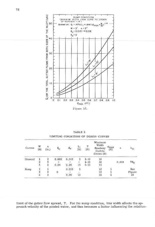
Bosed on : Oj =I 47b(L; +I SW) (dmax.+~ i'·"" W = 3 1
a = 3 11
Sx= 0.015 -0.06
LL So= 0 0 40 1---1--+--+---+--+--'1---+---1---W-____. el 0 iii :I: f-0 m :i' 30 1---1--+--t--+--+--'l---+--+---V--I 0 a:: LL
en
3 LL 20 1---1--+--l---+--+-~1---"""--1----.IL----< a:: ~ f::::> (!)
_J
~ I 0 1---1--+----~-i-7"'"-ll---+--t---+-____. f2 w :I: f-
a:: g a- o~~-~-~-~-~~~~-~-~~
0 0 I 0 .2 0.3 0.4 0 5 0.6 0.7 0 .8 0 .9 1.0
dma .. (FT.)
Figure 18.
TABLE 2
LIMITING CONDITIONS OF DESIGN CURVES
Minimum
a So Sx
Li T Width d
(in.) (ft) (ft) Roadway ft1t) Curb to
Crown (ft)
2 0.002 0.015 5 2-10 10 2 I l l 4-10 10 3 0.04 0.06 15 6-15 15
1 0.015 5 12 1 2 0 l l 12 1 3 0.06 15 18 1
n hm
0.016 TSx
See Figure
16
limit of the gutter flow spread, T. For the sump condition, this width affects the approach velocity of the ponded water, and thus becomes a factor influencing the relation-

77
ship between the maximum gutter water depth, dmax, and the capacity of the inlet. This is especially true for narrow streets. These sump curves are specified for the minimum roadway width from curb to crown. A lesser width may produce an effect that amounts to about a five percent increase in the maximum water depth, dmax, for a reduction of one-third of the specified width.
These design curves cover only the standard depression geometry of three different sizes with the a/W constant a 1/12. Consequently, they permit the selection of the best depression size for the particular situation. A conclusive evaluation of the effect of change in the a / W ratio is not possible on the basis of the data. However, limited experimental data for Sx = 0.015 and S0 = 0.04, show that for W = 2 ft, a reduction of the depression depth, a, from 2 in. to 1 in. may cause a maximum reduction of about onefourth in the interception rate, QJQ, of the inlet, while, for W = 1 ft, an increase of a from 1 in. to 2 in. can increase the QJQ by one-fourth. By holding a as constant: for a= 2 in., a reduction of W from 2 ft to 1 ft may reduce the QJQ by one-fourth; while, for a = 1 in., and increase of W from 1 ft to 2 ft can increase the QJQ by onefourth.
Application. -Although these new design curves cover a considerable range of practical conditions, there are still several cases yet to be studied: (1) The partially and completely submerged inlet; in the latter case, orifice type flow is developed. (2) other types of street cross-sections, particularly one in which the cross slope steepens abruptly at the line between gutter section and pavement proper. Use of the crown slope of the pavement for 8x and the calculated T for this condition will give conservative results, however. (3) Other a/ W ratios. ( 4) The effect of devices to deflect flow into the inlet.
The width of uniform gutter flow spread, T, can be computed from Izzard's integrated Manning formula (~) for street of single cross slope, Sx:
and
Q = 0. 56 ( n ~J S0 % d %
d T = -
Sx
The nomograph solution of Eq. 9 can be found in Design Charts for Open-Channel Flow (7).
(9)
(10)
Because of the special characteristics of the experimental study, extrapolation for conditions beyond the limits of Table 2 should be undertaken only with full recognition of the uncertainties involved. Linear interpolation can be applied.
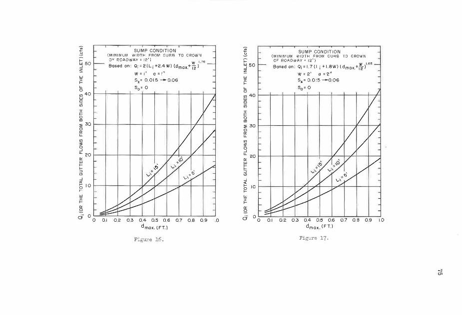
Figures 15 through 18 apply to the sump condition. All of the discharge coming to the sump from both sides is assumed to eventually pass through the inlet. The inlet discharge capacity is shown as a function of maximum gutter water depth at the curb face, and different curves are drawn for the different lengths of inlet. It is assumed that the height of the opening would be large enough to permit free fall (without orifice type flow) into the inlet box. Figure 15 shows the minimum opening heights for this condition. If this minimum is not met and the inlet is completely submerged, it is possible to calculate the discharge based on an orifice type flow assumption. There is, however, no experimental information about the partially submerged inlet.
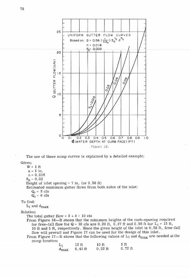
One important point in using these sump curves should be clarified. In the lower discharge ranges, the flow depth in approach gutters may be greater than depth, dmax, read from these curves. It is recommended that the uniform gutter flow water depth of S0 = O. 002, that will be at a point generally within 30 ft of the sump inlet, should be checked. For this reason Figure 19 for uniform gutter flow, based on Eq. 9 and n = 0.016, is provided. If the depth read from Figures 16 to 18 is less than this uniform gutter flow depth, flow will tend to draw down as it approaches the inlet. On the other hand, if sump depth is greater, then the pool backs up water along the gutter.
78
3:
UNI FORM GUTTER FLOW CURVES
Based on: Q = 0.56 ( n's ) sc:'2 d61
3 x
n = 0 .016 S0= 0 .002
20 1----;---t--+--+----l---+--+--l--l--~lt---l
:J I 5 1----ll---t---+--+-+ - -hl--1--+1--1----1 ll.
a: w ..... ..... ::J (!) ~ I 0 1----ll---t--l---+--1--1--l-- ./--.J--l----I a
0 01--diiiii~:::::::::J__L~L__L_J~J__J__J 0 .1 0 2 0 .3 0 4 0 .5 0 .6 0.7 0 .8 0 .9 1.0
d (WATER DEPTH AT CURB FACE) (FT.)
Figure 19.
The use of these sump curves is explained by a detailed example:
Given: w = 1 ft a= 1 in. n= 0.016
Sx = 0.03 Height of inlet opening = 7 in. (or 0. 58 ft) Estimated maximum gutter flows from both sides of the inlet:
Q1 = 2 cfs Q2 = 8 cfs
To find: Li and dmax
Solution: The total gutter flow = 2 + 8 = 10 cfs From Figure 16-It shows that the minimum heights of the curb-opening required
for free-fall flow for Q = 10 cfs are 0. 28 ft, 0. 37 ft and 0. 56 ft for Li = 15 ft, 10 ft and 5 ft , respectively. Since the given height of the inlet is 0. 58 ft, free-fall flow will prevail and Figure 17 can be used for the design of this inlet.
From Figure 17 -It shows that the following values of Li and dmax are needed at the 011,..,..,n ln£"".ltln.n• U""'-.O.A.A.z:' .LV"-'_.,...,.._, ... ,..
15 ft 0 .41 ft
10 ft 0. 52 ft
5 ft 0. 72 ft
79
From Figure 20-It shows that the values of d needed for uniform gutter flows are: Q 2 cfs 8 cfs d 0 . 3 ft 0 . 5 ft
Therefore: If Li = 15 ft is to be selected, then
dmax ( = 0. 41 ft) < d ( = 0. 5 ft for Q2 = 8 cfs), the gutter flow Q2 tends to draw down as it approaches the inlet; and
dmax ( = 0. 41 ft) > d ( = 0. 3 ft for Q1 = 2 cfs), the pool at the inlet backs up water along the gutter with Q1 •
If Li -= 10 ft or 5 ft is to be selected, then dmax ( = 0. 52 ft or 0. 72 ft) > d ( = 0. 5 ft or 0. 3 ft), the pool at the inlet backs
up water along both gutters.
COMPARISON OF THE NEW DESIGN CURVES TO OTHER AVAILABLE INFORMATION
Izzard's work (1) on the capacity of curb-opening inlets with and without depression has been widely used, but the effect of depression width was not taken into account because of the absence of data. When compared with the new experimental data, the old method tends to substantially underestimate the capacity of inlets with depression widths greater than one foot.
Another often quoted work is Johns Hopkins University's "The Design of Storm-Water Inlets" (2). Although the curves for depressed curb-opening inlets in this publication are for fii.e Baltimore depression only, those for other depression geometry can be computed by using its suggested method. The curves thus derived show higher interception rates than the new design curves presented here. The reason for this discrepancy must be in the differences in the experimental conditions, illustrating that an empirical method derived from experimental data of certain conditions is best applied only within these same limits.
CONCLUSION
The new design curves are more comprehensive then those previously available. They are believed to be easier to use, because they give a direct answer with a minimum amount of calculation.
Future research could be applied to other depression shapes, to the effect of submergence of the opening, to the effect of gutters of different cross-sections, and to the effect of devices to deflect flow into the inlet. Other aspects of natural gutter flow that were ignored in this study as being relatively insignificant in determining inlet efficiencies in the usual case are unsteadiness (variation of discharge with time) and nonuniformity (variation of discharge with position along the gutter). Flow that is decidedly unsteady (for example, slug flow) or decidedly nonuniform (such as a large component of flow entering at an angle to the line of the gutter) could also be studied in future research, as could be the inlet on a curve.
ACKNOWLEDGMENT
This is the primary report on research on this subject conducted in cooperation with the U. S. Bureau of Public Roads. The authors acknowledge the leadership of Carl F. Izzard, Chief, Hydraulic Research Division, U. S. Bureau of Public Roads, in all of the work culminating in this paper. The authors also recognize the fine work done by staff of Colorado state University Research Foundation, particularly S. Karaki, who were responsible for a major portion of the laboratory work. Finally the authors acknowledge the valuable suggestion about condensing the curves for the general condition made by Lester A. Herr, Chief, Hydraulic Branch, U. S. Bureau of Public Roads.
REFERENCES
1. Izzard, C. F., "Tentative Results on Capacity of Curb-Opening Inlets." HRB, Res. Rept. No. 11-B, "Surface Drainage" (1950).
80
2. Johns Hopkins Univ., "The Design of Storm-Water Inlets." Rept. of the Storm Drainage Res. Comm, of the Storm Drainage Res. Proj. (JnnP 1 fl~fi).
3 . Wasley, R. J., "Hydrodynamics of Flow into Curb-Opening Inlets. " J our. Eng. Mech., ASCE, Vol. 87 (Aug. 1961).
4. City of Los Angeles, "Design Charts for Catch Basin Openings as Determined by Experimental Hydraulic Model Studies." Office Standard 108, Storm Drain Des. Div., Bur. of Eng. (1956).
5. Rouse, H., Bhoota, B. V., and Hsu, E. Y., "High-Velocity Flow in Open Channels (symposium): Design of Channel Expansion." Trans. ASCE, Vol. 116 (1951).
6. Izzard, C. F. , Discussion of "Experiments on Flow Through Inlet Gratings for Street Gutters," by C. L. Larson. HRB, Res. Rept. 6-B, "Surface Drainage of Highways" ( 1948).
7. "Design Charts for Open-Channel Flow." Hydraulic Design Series 3, U. S. Bur. of Public Roads (Aug. 1961).