
HYDRAULIC CONTROL VALVE - DICKEY-john Control Valve 11001-1640-201309 2/ INSTALLATION INSTRUCTIONS...
6
INSTALLATION INSTRUCTIONS Hydraulic Control Valve 11001-1640-201309 /1 HYDRAULIC CONTROL VALVE The hydraulic control valve can mount in any location that is protected from abusive environmental conditions. Mounting position recommendations noted in Figure 1. IMPORTANT: After mounting, the valve, mounting brackets, and bolts should be coated with oil, grease, or paint to provide an oxidation barrier. Figure 1 Control Valve Dimensions for 58 GPM and all other Valves • Hydraulic hose requires a minimum operating rating of 2250 psi working. • Hydraulic control valve ports are threaded. • Use the hose manufacturer’s recommended fittings. Avoid sharp bends when installing hoses to avoid damage during spreader operation.
Transcript of HYDRAULIC CONTROL VALVE - DICKEY-john Control Valve 11001-1640-201309 2/ INSTALLATION INSTRUCTIONS...
INSTALLATION INSTRUCTIONS
Hydraulic Control Valve
11001-1640-201309
/ 1
HYDRAULIC CONTROL VALVE
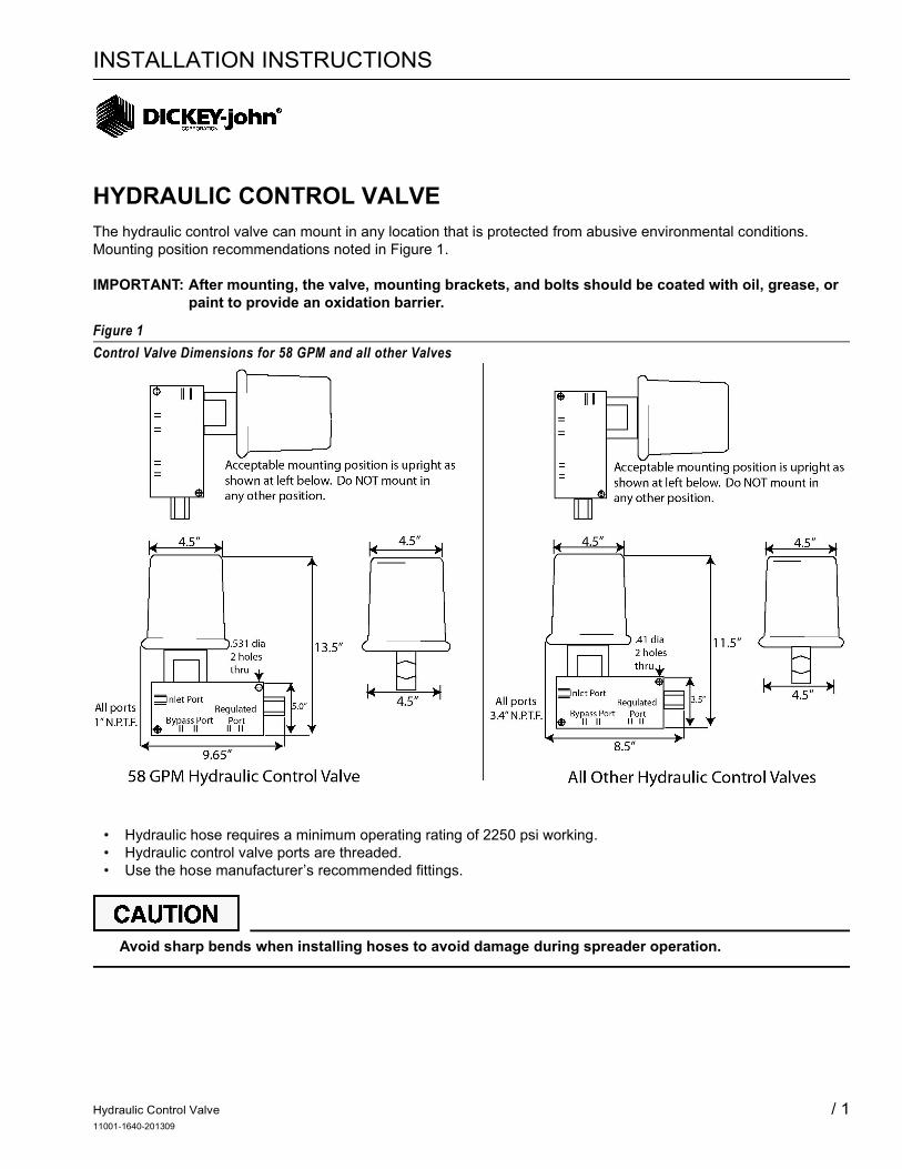
The hydraulic control valve can mount in any location that is protected from abusive environmental conditions. Mounting position recommendations noted in Figure 1.
IMPORTANT: After mounting, the valve, mounting brackets, and bolts should be coated with oil, grease, or paint to provide an oxidation barrier.
Figure 1
Control Valve Dimensions for 58 GPM and all other Valves
• Hydraulic hose requires a minimum operating rating of 2250 psi working. • Hydraulic control valve ports are threaded.• Use the hose manufacturer’s recommended fittings.
Avoid sharp bends when installing hoses to avoid damage during spreader operation.

Hydraulic Control Valve11001-1640-201309
2 /
INSTALLATION INSTRUCTIONS
CONNECTION
Connect the hydraulic control valve into system following the appropriate illustration. Verify control lines conform to standard hydraulic practice for flow rates and that a 10-micron filter is installed in the suction line.
IMPORTANT: Always use a thread sealant on male fittings.
Figure 2
Fixed Displacement Hydraulic Pump System
Figure 3
Hydraulic Circuit of Fixed Displacement Hydraulic Pump System

Hydraulic Control Valve11001-1640-201309
/ 3
INSTALLATION INSTRUCTIONS
Figure 4
Fixed Displacement Hydraulic Pump System
Figure 5
Hydraulic Circuit of Fixed Displacement Hydraulic Pump System

Hydraulic Control Valve11001-1640-201309
4 /
INSTALLATION INSTRUCTIONS
Figure 6
Variable Displacement Hydraulic Pump System
Figure 7
Hydraulic Circuit of Variable Displacement Hydraulic Pump System
Hydraulic Control Valve11001-1640-201309
/ 5
INSTALLATION INSTRUCTIONS
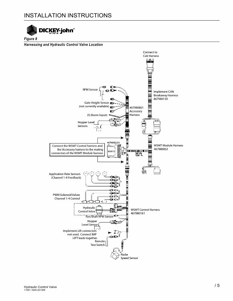
Figure 8
Harnessing and Hydraulic Control Valve Location

Hydraulic Control Valve11001-1640-201309
6 /
INSTALLATION INSTRUCTIONS


