
Operation of split air conditioning systems with hydrocarbon refrigerant
HYDRAULIC CONDITIONING UNIT INSTALLATION/ OPERATION/ SERVICE MANUAL

AKG THERMAL SYSTEMS, INC. HYDRAULIC CONDITIONING UNIT (HCU)
INSTALLATION/OPERATION/SERVICE MANUAL
1 |Page
Congratulations on your selection of AKG’s Hydraulic Conditioning Unit! We are certain that you will be pleased with your selection of the HCU, one of the best products in the market. This manual will help you get the best performance and safe operation from the AKG HCU. Please read the instructions carefully on how to operate your HCU. AKG reserves the right to alter the HCU without notice. This manual may not be reproduced without permission. Please keep this owner’s manual available so it can be used as a reference throughout the product life-cycle. This manual is a permanent part of the HCU and should always remain with the unit. Please read the warranty policies to fully understand the terms and conditions, coverage and responsibilities of ownership. Thank you for purchasing your HCU and please communicate any questions/comments to [email protected] or give us a call at 919-563-4871.

AKG THERMAL SYSTEMS, INC. HYDRAULIC CONDITIONING UNIT (HCU)
INSTALLATION/OPERATION/SERVICE MANUAL
2 |Page
Table of Contents
1. Safety First! ......................................................................................3 2. Installation ........................................................................................ 5
2.1 What’s in the box? 2.2 How to Install the HCU?
2.2.1 Hydraulic Fan Drive Schematic 2.2.2 Brushed DC Fan Drive Schematic 2.2.3 Brushless DC Fan Drive Schematic
3. Operation ......................................................................................... 11 3.1 Startup Procedure 3.2 Open Loop and Closed Loop Systems 3.3 Weather Conditions
3.3.1 Material Compatibility 4. Technical Specifications ................................................................ 13
4.1 Hydraulic Reservoir 4.2 Oil Cooler 4.3 Fan Drive
4.3.1 Hydraulic Fan Drive 4.3.1.1 Hydraulic Motor 4.3.1.2 Hydraulic Full System Relief Manifold
4.3.2 Brushed DC Fan Drive 4.3.2.1 Temperature Switch
4.3.3 Brushless DC Fan Drive 4.3.3.1 PWM Controller/Harness
5. Maintenance .................................................................................... 19 5.1 How to Change the Filter/Breather? 5.2 System Maintenance 5.3 How to Change Hydraulic Oil 5.4 Cleaning Oil Cooler
6. Troubleshooting .............................................................................. 23 7. Service Parts List. ........................................................................... 24 8. Warranty and Returns ......................................................................28 9. Contact Us ........................................................................................ 29
AKG THERMAL SYSTEMS, INC. HYDRAULIC CONDITIONING UNIT (HCU)
INSTALLATION/OPERATION/SERVICE MANUAL
3 |Page
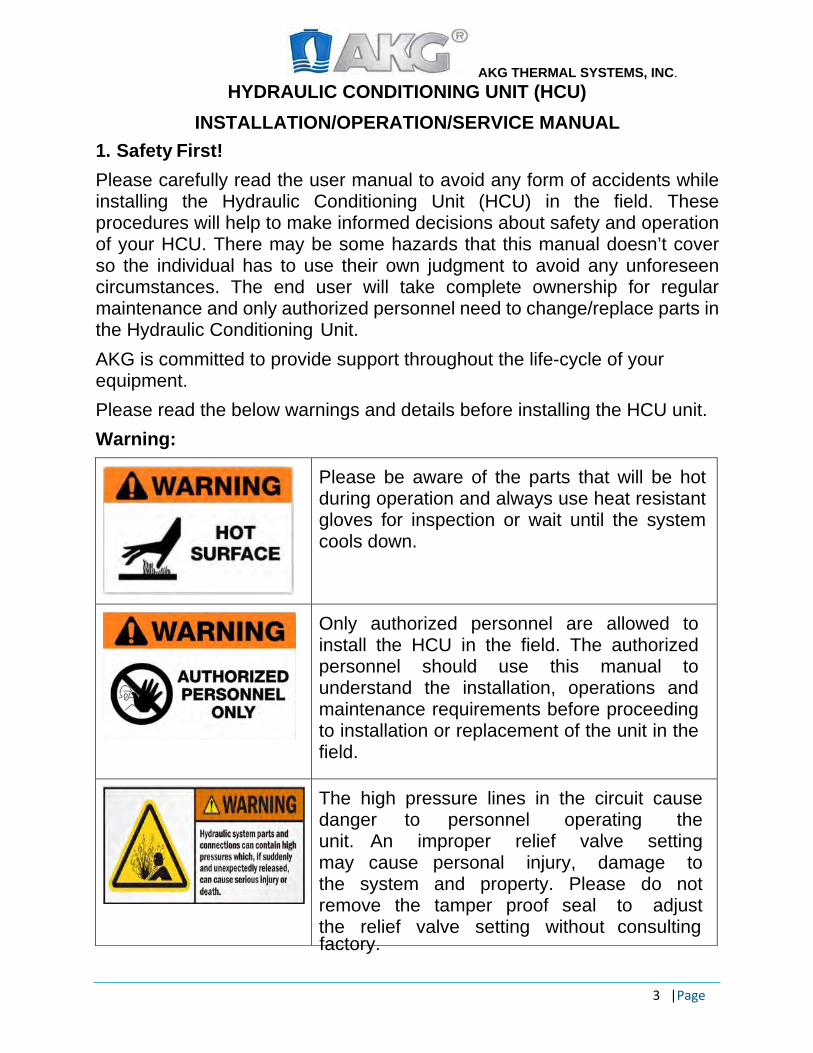
1. Safety First! Please carefully read the user manual to avoid any form of accidents while installing the Hydraulic Conditioning Unit (HCU) in the field. These procedures will help to make informed decisions about safety and operation of your HCU. There may be some hazards that this manual doesn’t cover so the individual has to use their own judgment to avoid any unforeseen circumstances. The end user will take complete ownership for regular maintenance and only authorized personnel need to change/replace parts in the Hydraulic Conditioning Unit. AKG is committed to provide support throughout the life-cycle of your equipment. Please read the below warnings and details before installing the HCU unit. Warning:
factory.
Please be aware of the parts that will be hot during operation and always use heat resistant gloves for inspection or wait until the system cools down.
Only authorized personnel are allowed to install the HCU in the field. The authorized personnel should use this manual to understand the installation, operations and maintenance requirements before proceeding to installation or replacement of the unit in the field.
The high pressure lines in the circuit cause danger to personnel operating the unit. An improper relief valve setting may cause personal injury, damage to the system and property. Please do not remove the tamper proof seal to adjust the relief valve setting without consulting
AKG THERMAL SYSTEMS, INC. HYDRAULIC CONDITIONING UNIT (HCU)
INSTALLATION/OPERATION/SERVICE MANUAL
4 |Page
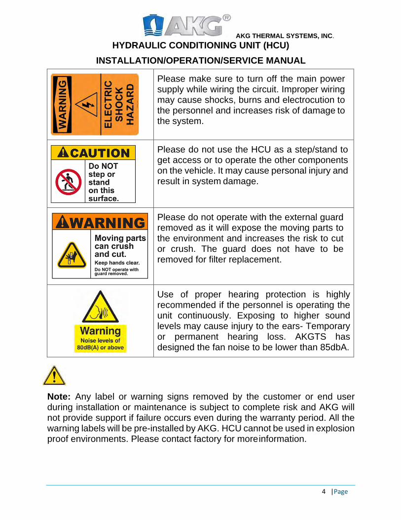
Please make sure to turn off the main power supply while wiring the circuit. Improper wiring may cause shocks, burns and electrocution to the personnel and increases risk of damage to the system.
Please do not use the HCU as a step/stand to get access or to operate the other components on the vehicle. It may cause personal injury and result in system damage.
Please do not operate with the external guard removed as it will expose the moving parts to the environment and increases the risk to cut or crush. The guard does not have to be removed for filter replacement.
Use of proper hearing protection is highly recommended if the personnel is operating the unit continuously. Exposing to higher sound levels may cause injury to the ears- Temporary or permanent hearing loss. AKGTS has designed the fan noise to be lower than 85dbA.
Note: Any label or warning signs removed by the customer or end user during installation or maintenance is subject to complete risk and AKG will not provide support if failure occurs even during the warranty period. All the warning labels will be pre-installed by AKG. HCU cannot be used in explosion proof environments. Please contact factory for more information.
AKG THERMAL SYSTEMS, INC. HYDRAULIC CONDITIONING UNIT (HCU)
INSTALLATION/OPERATION/SERVICE MANUAL
5 |Page
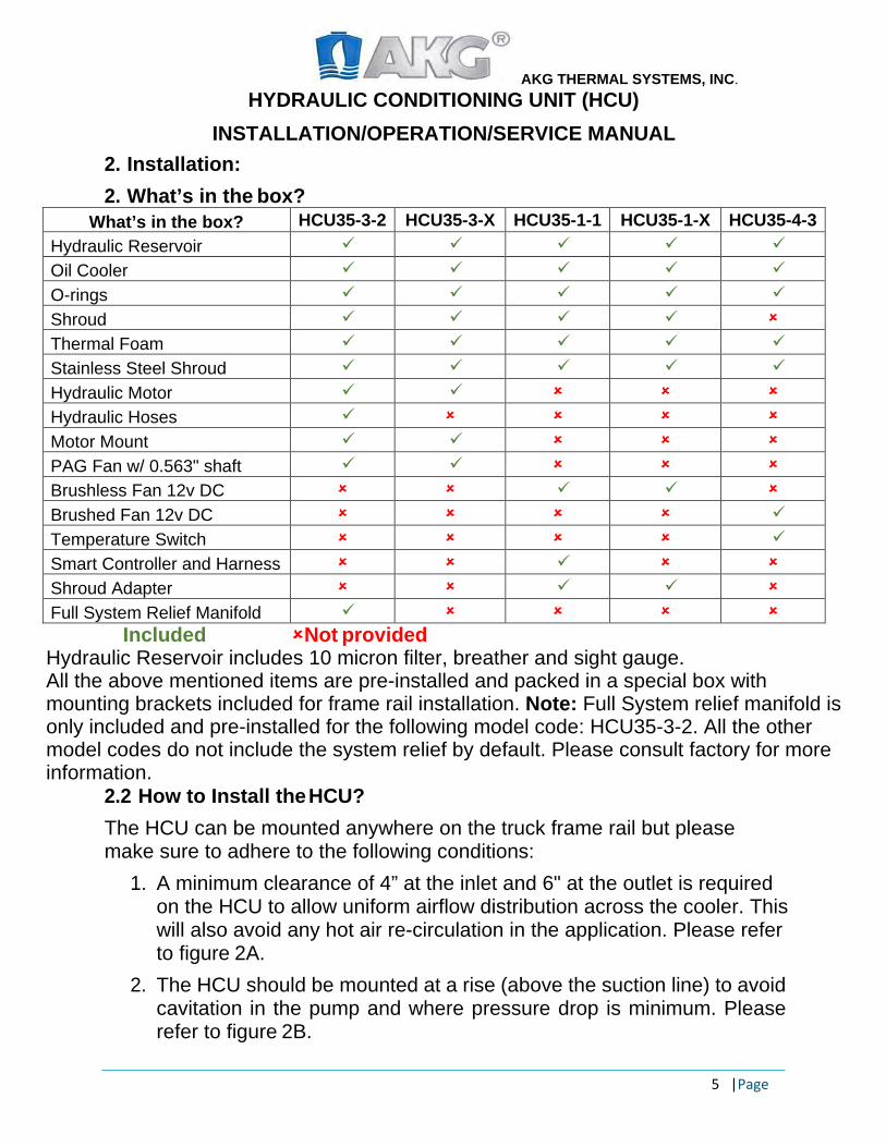
2. Installation: 2. What’s in the box?
What’s in the box? HCU35-3-2 HCU35-3-X HCU35-1-1 HCU35-1-X HCU35-4-3 Hydraulic Reservoir Oil Cooler O-rings Shroud Thermal Foam Stainless Steel Shroud Hydraulic Motor Hydraulic Hoses Motor Mount PAG Fan w/ 0.563" shaft Brushless Fan 12v DC Brushed Fan 12v DC Temperature Switch Smart Controller and Harness Shroud Adapter Full System Relief Manifold
Included Not provided Hydraulic Reservoir includes 10 micron filter, breather and sight gauge. All the above mentioned items are pre-installed and packed in a special box with mounting brackets included for frame rail installation. Note: Full System relief manifold is only included and pre-installed for the following model code: HCU35-3-2. All the other model codes do not include the system relief by default. Please consult factory for more information.
2.2 How to Install the HCU? The HCU can be mounted anywhere on the truck frame rail but please make sure to adhere to the following conditions:
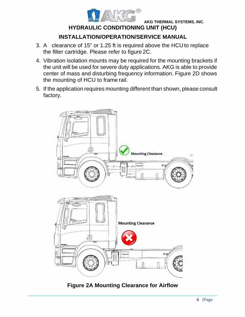
1. A minimum clearance of 4” at the inlet and 6" at the outlet is required on the HCU to allow uniform airflow distribution across the cooler. This will also avoid any hot air re-circulation in the application. Please refer to figure 2A.
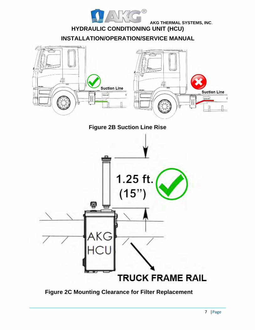
2. The HCU should be mounted at a rise (above the suction line) to avoid cavitation in the pump and where pressure drop is minimum. Please refer to figure 2B.
AKG THERMAL SYSTEMS, INC. HYDRAULIC CONDITIONING UNIT (HCU)
INSTALLATION/OPERATION/SERVICE MANUAL
6 |Page
3. A clearance of 15” or 1.25 ft is required above the HCU to replace the filter cartridge. Please refer to figure 2C.
4. Vibration isolation mounts may be required for the mounting brackets if the unit will be used for severe duty applications. AKG is able to provide center of mass and disturbing frequency information. Figure 2D shows the mounting of HCU to frame rail.
5. If the application requires mounting different than shown, please consult factory.
Figure 2A Mounting Clearance for Airflow
AKG THERMAL SYSTEMS, INC. HYDRAULIC CONDITIONING UNIT (HCU)
INSTALLATION/OPERATION/SERVICE MANUAL
7 |Page
Figure 2B Suction Line Rise
Figure 2C Mounting Clearance for Filter Replacement

AKG THERMAL SYSTEMS, INC. HYDRAULIC CONDITIONING UNIT (HCU)
INSTALLATION/OPERATION/SERVICE MANUAL
8 |Page
Figure 2D Installing the HCU to Frame Rail
2.2.1 Hydraulic Fan Drive Schematic: The hydraulic Fan Drive schematic is shown in the figure 2E with the full system relief valve. The hydraulic fan motor receives flow from the full system relief valve. The outlet of the hydraulic motor is directly plumbed to the hydraulic reservoir. It is the responsibility of the customer to use a relief valve in the system if it is not purchased from AKG. Please refer to the last page for torque specs.
Figure 2E HCU Hydraulic Fan Drive Schematic
AKG THERMAL SYSTEMS, INC. HYDRAULIC CONDITIONING UNIT (HCU)
INSTALLATION/OPERATION/SERVICE MANUAL
9 | Page
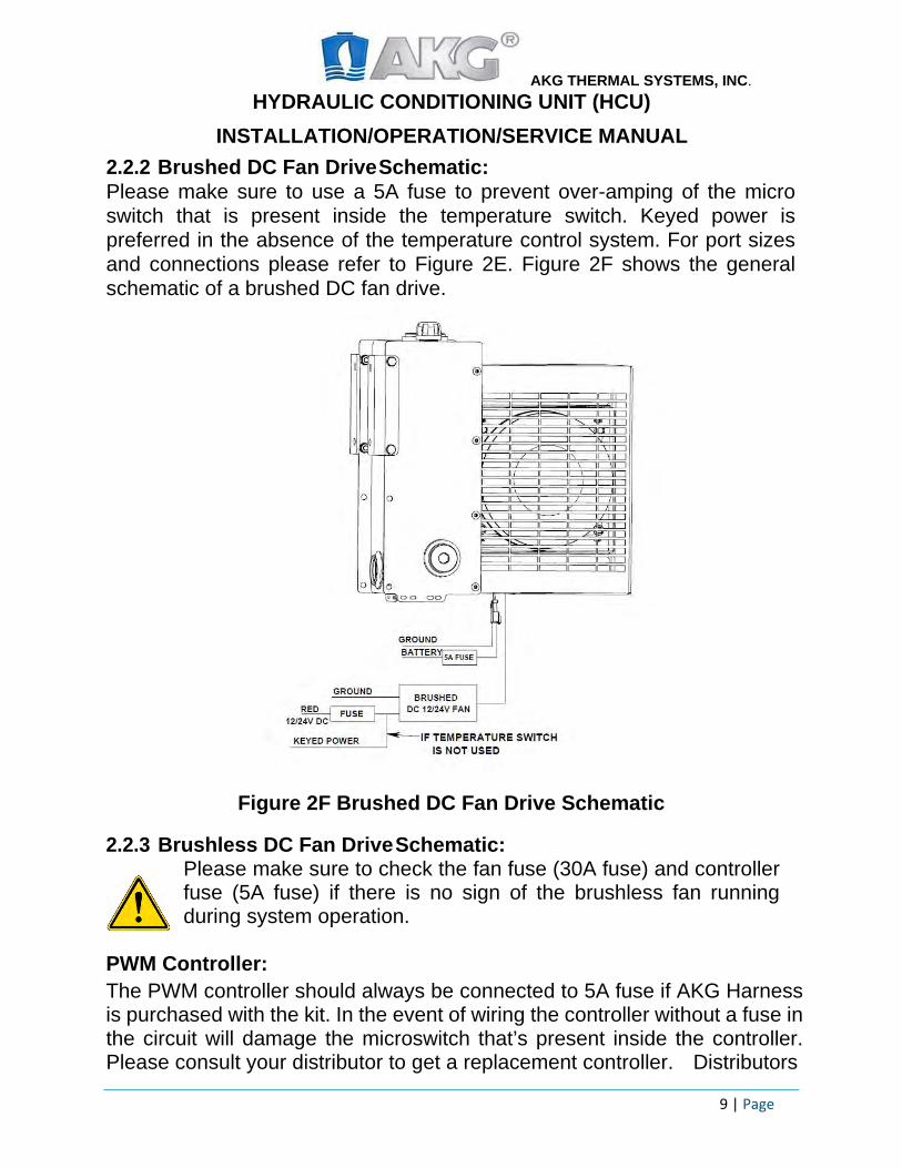
2.2.2 Brushed DC Fan Drive Schematic: Please make sure to use a 5A fuse to prevent over-amping of the micro switch that is present inside the temperature switch. Keyed power is preferred in the absence of the temperature control system. For port sizes and connections please refer to Figure 2E. Figure 2F shows the general schematic of a brushed DC fan drive.
Figure 2F Brushed DC Fan Drive Schematic
2.2.3 Brushless DC Fan Drive Schematic: Please make sure to check the fan fuse (30A fuse) and controller fuse (5A fuse) if there is no sign of the brushless fan running during system operation.
PWM Controller: The PWM controller should always be connected to 5A fuse if AKG Harness is purchased with the kit. In the event of wiring the controller without a fuse in the circuit will damage the microswitch that’s present inside the controller. Please consult your distributor to get a replacement controller. Distributors

AKG THERMAL SYSTEMS, INC. HYDRAULIC CONDITIONING UNIT (HCU)
INSTALLATION/OPERATION/SERVICE MANUAL
10 | Page
can directly consult with factory to get a replacement controller. For port call- outs and sizes please refer to Figure 2E. Figure 2G shows the general schematic of a brushless fan drive.
Figure 2G Brushless Fan Drive Schematic

AKG THERMAL SYSTEMS, INC. HYDRAULIC CONDITIONING UNIT (HCU)
INSTALLATION/OPERATION/SERVICE MANUAL
11 | Page
3. Operation: 3.1 Startup Procedure:
1. Fill the system with the recommended oil until it reaches the top of the sight gauge. Please make sure the oil used fulfills the hydraulic manufacturer’s requirements.
2. Please make sure to check the hoses and fittings are all plumbed properly and tightened before filling with oil.
3. Engage the PTO with a switch 4. Inspect the pump speed, pressure lines for leaks, check oil level in the
sight gauge and add more oil until it reaches the top portion of the sight gauge.
5. Let the system run for a couple of minutes to make sure the HCU is running smoothly
6. Please check the airflow direction and fan orientation (hydraulic fan drive). The fan should spin counter clockwise direction by pulling air through the cooler and blowing it towards the fan-motor.
7. Reduce the engine speed to idle and disengage the PTO 8. Oil should be changed after 10 hours of operation to get rid of any
contaminants from the system or based on hydraulic manufacturer’s requirements.
Note: If there are any leaks during start up shut down the system immediately and inspect/tighten the lines leaking connections. Please consult factory if you continue to see this problem.
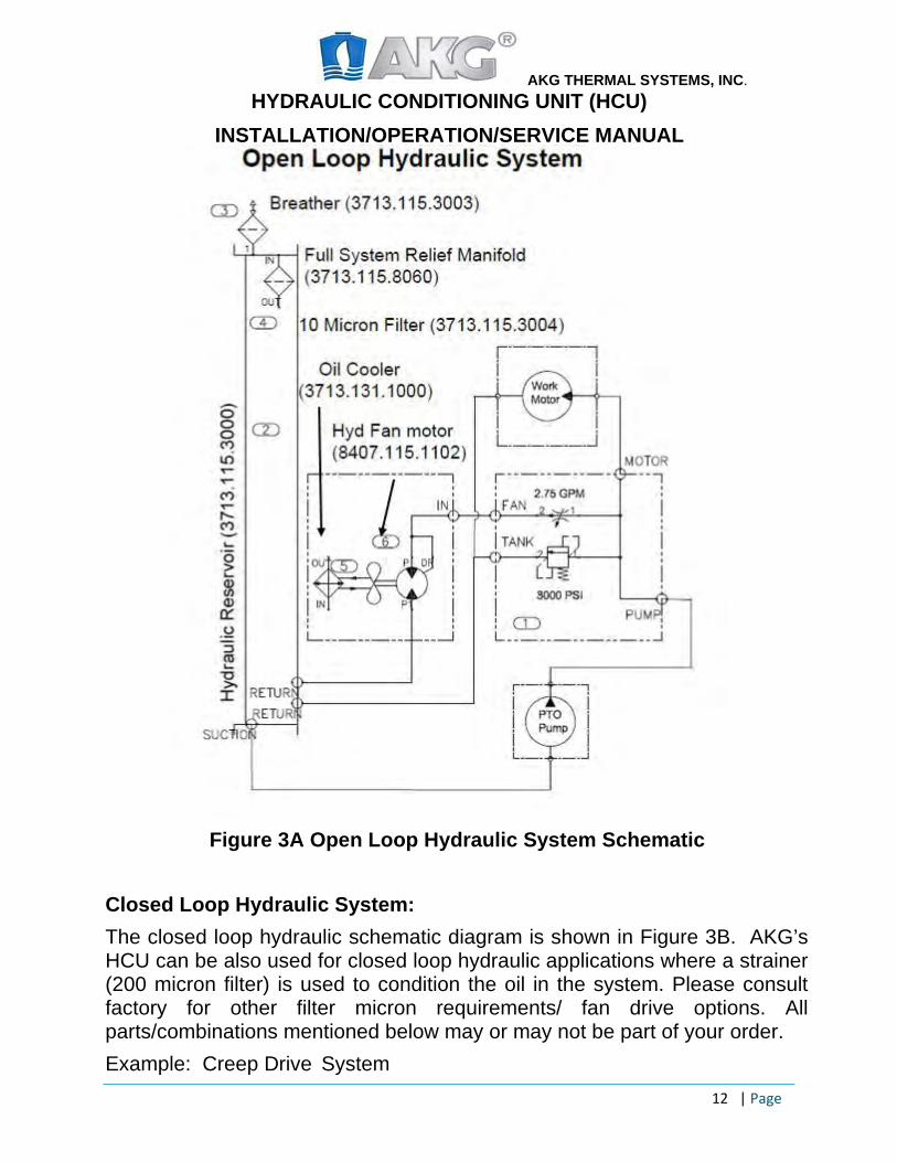
3.2 Open Loop System and Closed Loop System Open Loop Hydraulic System
Figure 3A shows the open loop hydraulic schematic diagram. The HCU is primarily designed for open loop hydraulic system where it utilizes different fan drive options such as hydraulic, brushed and brushless version to run the cooling fan to continuously condition the oil in the hydraulic system. Example: Tanker trucks, bulk feed trucks, etc.
Note: The schematic shown below (Figure 3A/3B) is just an example and the parts may or may not be a part of the system depending on the order/ model code. For example, If the order placed is for a HCU35-1-1, then, the assembly won’t include the system relief (3713.115.8060). Please consult factory if you have any questions.
AKG THERMAL SYSTEMS, INC. HYDRAULIC CONDITIONING UNIT (HCU)
INSTALLATION/OPERATION/SERVICE MANUAL
12 | Page
Figure 3A Open Loop Hydraulic System Schematic
Closed Loop Hydraulic System: The closed loop hydraulic schematic diagram is shown in Figure 3B. AKG’s HCU can be also used for closed loop hydraulic applications where a strainer (200 micron filter) is used to condition the oil in the system. Please consult factory for other filter micron requirements/ fan drive options. All parts/combinations mentioned below may or may not be part of your order. Example: Creep Drive System

AKG THERMAL SYSTEMS, INC. HYDRAULIC CONDITIONING UNIT (HCU)
INSTALLATION/OPERATION/SERVICE MANUAL
13 | Page
Figure 3B Closed Loop Hydraulic System Schematic
3.3 Weather Conditions: 3.3.1 Material Compatibility: HCU is designed to work well for all weather conditions when mounted to a truck frame rail. Please see below for the list of materials used for different parts: Hydraulic Reservoir: High Carbon Manifold: Anodized Aluminum Electric fans/controller: IP68 rated
Oil cooler: Aluminum Shroud: Stainless Steel
Fan: Plastic
4. Technical Specifications: 4.1 Hydraulic Reservoir: HCU’s hydraulic reservoir can handle up to 35 gpm with < .5% air entrapment as it uses state-of-the-art Hydro nucleation technology to reduce cavitation. The hydraulic reservoir is made out of high Carbon Steel and internally fogged after production to prevent rust.

AKG THERMAL SYSTEMS, INC. HYDRAULIC CONDITIONING UNIT (HCU)
INSTALLATION/OPERATION/SERVICE MANUAL
14 | Page
The volume of the hydraulic reservoir is 3.9 gallons and it has three function ports. The bottom of the tank has two ports, the first is the return port to the filter which is an SAE-16 port and the second port is an SAE-8 port for the drain. The back of the tank has the suction port SAE-24 and additional SAE- 8 sensor port. On the front side of the reservoir there is an SAE-8 port which can be used as for multiple purposes including case drain for the hydraulic fan drive motor, or brushless controller or temperature switch for the brushed DC fan. All of the HCU’s have inside out filter and the filter element has a nominal flow rating of 40 gpm. The filtration has molded in-seal plastisol end caps. The filter has an efficiency rating of 10 micron at 60 Beta. The maximum temperature rating is 200F. The filter also comes with a bypass and it is rated for 25psi.
Caution: Do not open the internal bypass valve assembly port. Warranty is void if it has been opened, tampered or damaged by the customer. Figure 4A represents the valve assembly clean out port.
Figure 4A Valve Assembly Clean Out port
4.2 Oil Cooler: The HCU uses an oil cooler with an internally plumbed design to minimize the failure of hoses/fittings, cost and space. The oil cooler is rugged aluminum, bar-plate construction, and has a non-fouling fin type that works well in all environments. Moreover, oil coolers have AKG’s patented flex profiles to reduce thermal fatigue and increase the service life of the cooler. The cooler volume is approximately 0.45 gallons.
AKG THERMAL SYSTEMS, INC. HYDRAULIC CONDITIONING UNIT (HCU)
INSTALLATION/OPERATION/SERVICE MANUAL
15 | Page
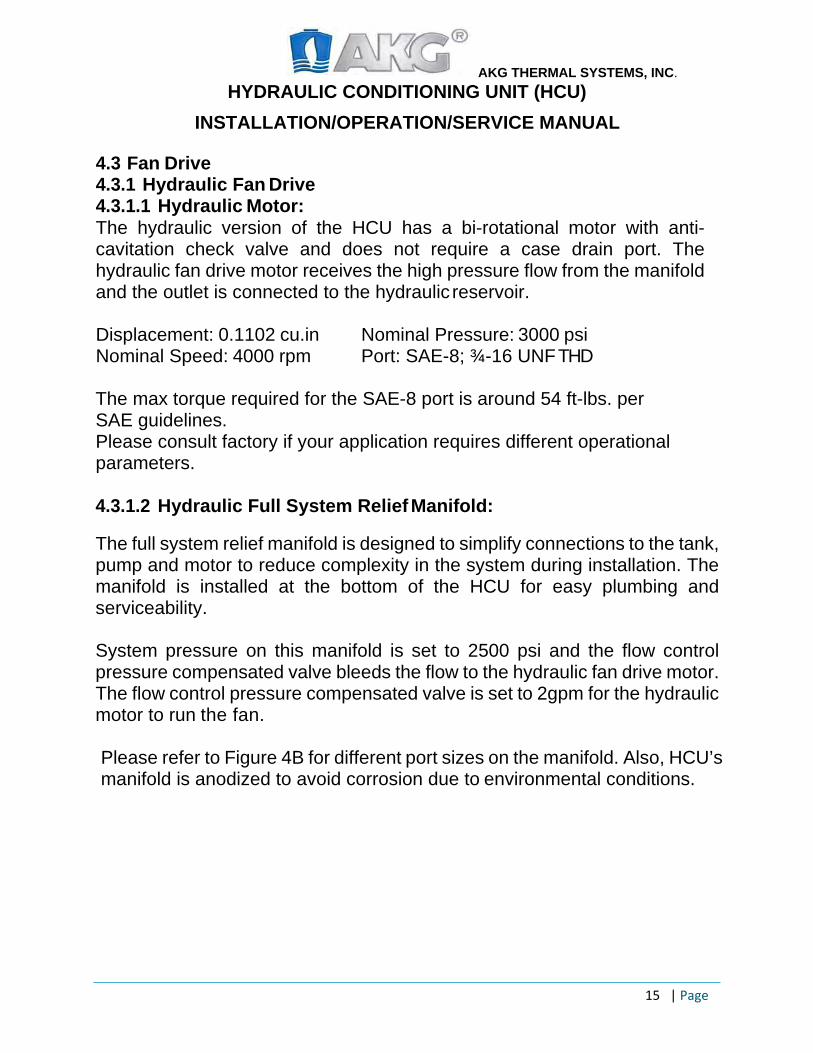
4.3 Fan Drive 4.3.1 Hydraulic Fan Drive 4.3.1.1 Hydraulic Motor: The hydraulic version of the HCU has a bi-rotational motor with anti- cavitation check valve and does not require a case drain port. The hydraulic fan drive motor receives the high pressure flow from the manifold and the outlet is connected to the hydraulic reservoir.
Displacement: 0.1102 cu.in Nominal Pressure: 3000 psi Nominal Speed: 4000 rpm Port: SAE-8; ¾-16 UNF THD
The max torque required for the SAE-8 port is around 54 ft-lbs. per SAE guidelines. Please consult factory if your application requires different operational parameters.
4.3.1.2 Hydraulic Full System Relief Manifold:
The full system relief manifold is designed to simplify connections to the tank, pump and motor to reduce complexity in the system during installation. The manifold is installed at the bottom of the HCU for easy plumbing and serviceability.
System pressure on this manifold is set to 2500 psi and the flow control pressure compensated valve bleeds the flow to the hydraulic fan drive motor. The flow control pressure compensated valve is set to 2gpm for the hydraulic motor to run the fan.
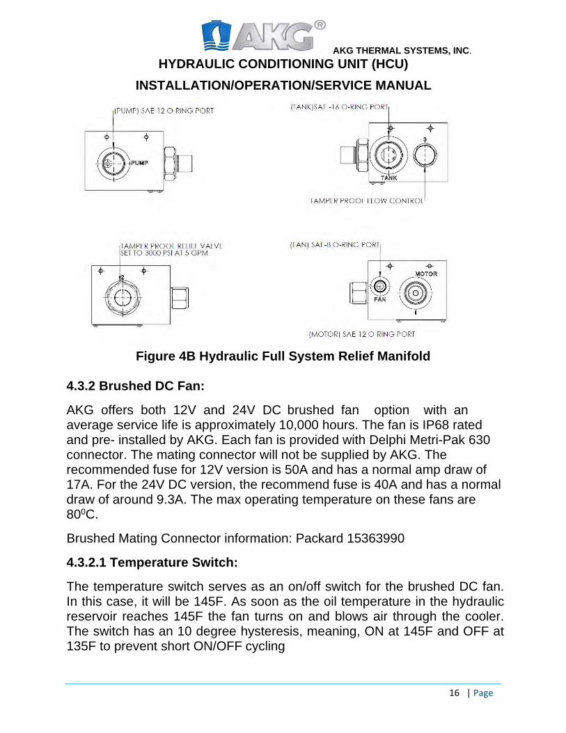
Please refer to Figure 4B for different port sizes on the manifold. Also, HCU’s manifold is anodized to avoid corrosion due to environmental conditions.
AKG THERMAL SYSTEMS, INC. HYDRAULIC CONDITIONING UNIT (HCU)
INSTALLATION/OPERATION/SERVICE MANUAL
16 | Page
Figure 4B Hydraulic Full System Relief Manifold 4.3.2 Brushed DC Fan:
AKG offers both 12V and 24V DC brushed fan option with an average service life is approximately 10,000 hours. The fan is IP68 rated and pre- installed by AKG. Each fan is provided with Delphi Metri-Pak 630 connector. The mating connector will not be supplied by AKG. The recommended fuse for 12V version is 50A and has a normal amp draw of 17A. For the 24V DC version, the recommend fuse is 40A and has a normal draw of around 9.3A. The max operating temperature on these fans are 800C.
Brushed Mating Connector information: Packard 15363990
4.3.2.1 Temperature Switch:
The temperature switch serves as an on/off switch for the brushed DC fan. In this case, it will be 145F. As soon as the oil temperature in the hydraulic reservoir reaches 145F the fan turns on and blows air through the cooler. The switch has an 10 degree hysteresis, meaning, ON at 145F and OFF at 135F to prevent short ON/OFF cycling
AKG THERMAL SYSTEMS, INC. HYDRAULIC CONDITIONING UNIT (HCU)
INSTALLATION/OPERATION/SERVICE MANUAL
17 | Page
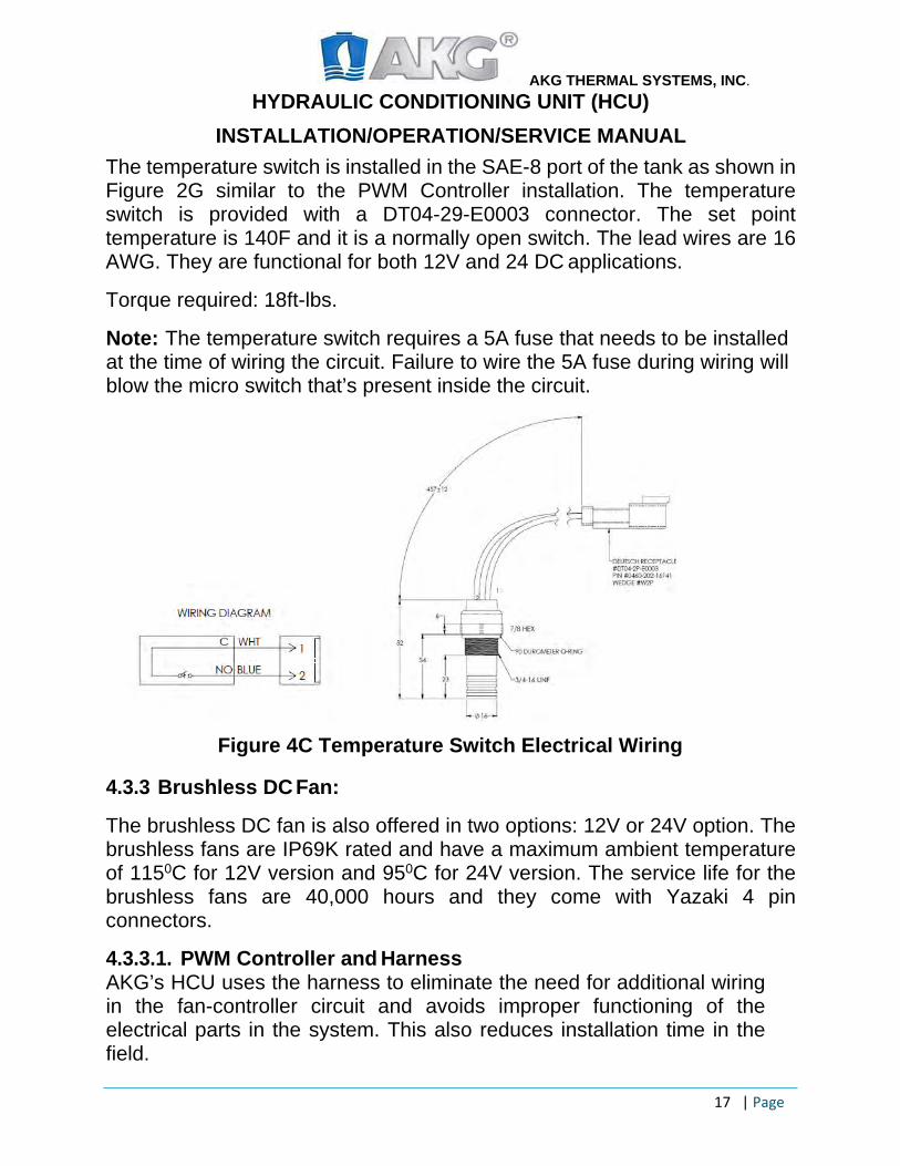
The temperature switch is installed in the SAE-8 port of the tank as shown in Figure 2G similar to the PWM Controller installation. The temperature switch is provided with a DT04-29-E0003 connector. The set point temperature is 140F and it is a normally open switch. The lead wires are 16 AWG. They are functional for both 12V and 24 DC applications.
Torque required: 18ft-lbs.
Note: The temperature switch requires a 5A fuse that needs to be installed at the time of wiring the circuit. Failure to wire the 5A fuse during wiring will blow the micro switch that’s present inside the circuit.
Figure 4C Temperature Switch Electrical Wiring
4.3.3 Brushless DC Fan:
The brushless DC fan is also offered in two options: 12V or 24V option. The brushless fans are IP69K rated and have a maximum ambient temperature of 1150C for 12V version and 950C for 24V version. The service life for the brushless fans are 40,000 hours and they come with Yazaki 4 pin connectors.
4.3.3.1. PWM Controller and Harness AKG’s HCU uses the harness to eliminate the need for additional wiring in the fan-controller circuit and avoids improper functioning of the electrical parts in the system. This also reduces installation time in the field.
AKG THERMAL SYSTEMS, INC. HYDRAULIC CONDITIONING UNIT (HCU)
INSTALLATION/OPERATION/SERVICE MANUAL
18 | Page
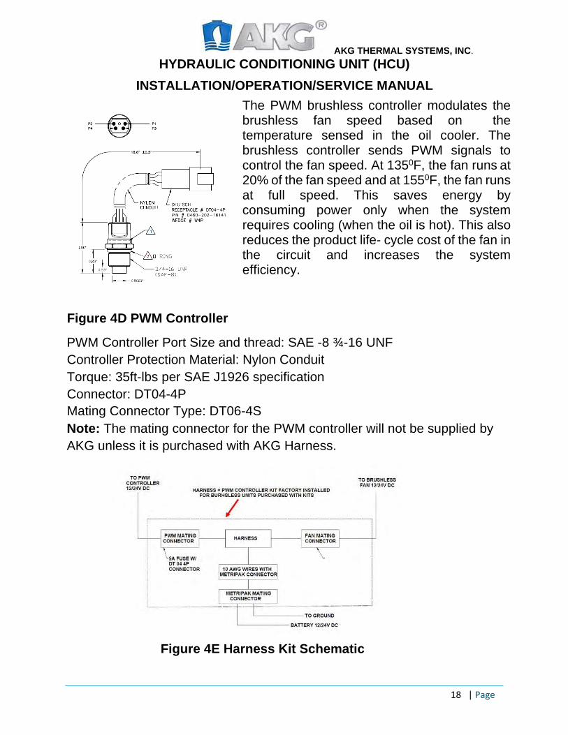
The PWM brushless controller modulates the brushless fan speed based on the temperature sensed in the oil cooler. The brushless controller sends PWM signals to control the fan speed. At 1350F, the fan runs at 20% of the fan speed and at 1550F, the fan runs at full speed. This saves energy by consuming power only when the system requires cooling (when the oil is hot). This also reduces the product life- cycle cost of the fan in the circuit and increases the system efficiency.
Figure 4D PWM Controller
PWM Controller Port Size and thread: SAE -8 ¾-16 UNF Controller Protection Material: Nylon Conduit Torque: 35ft-lbs per SAE J1926 specification Connector: DT04-4P Mating Connector Type: DT06-4S Note: The mating connector for the PWM controller will not be supplied by AKG unless it is purchased with AKG Harness.
Figure 4E Harness Kit Schematic
AKG THERMAL SYSTEMS, INC. HYDRAULIC CONDITIONING UNIT (HCU)
INSTALLATION/OPERATION/SERVICE MANUAL
19 | Page
The brushless harness has the following parts: PWM mating connector, Splice box, Fan-Mating connector, Fan Maxi blow Fuse, PWM controller fuse, 10 AWG Lead wires with Metri- Pak Connector. A mating connector for the Metri-Pak is also provided so customers can use it for wiring it to the batteries.
The brushless harness comes with a nylon loom to protect the wires from dust, debris and water. This harness can be used for both 12V and 24V DC fan. The power source to the brushless fan drive should be always taken from the main source (battery).
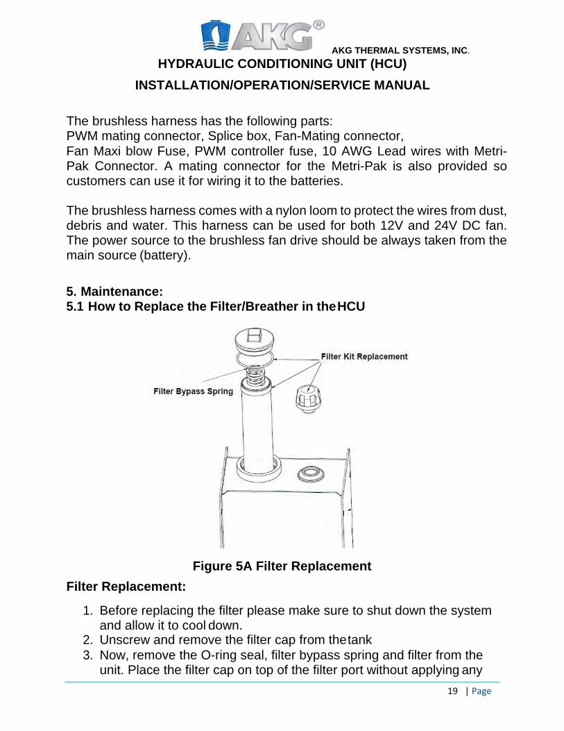
5. Maintenance: 5.1 How to Replace the Filter/Breather in the HCU
Figure 5A Filter Replacement Filter Replacement:
1. Before replacing the filter please make sure to shut down the system and allow it to cool down.
2. Unscrew and remove the filter cap from the tank 3. Now, remove the O-ring seal, filter bypass spring and filter from the
unit. Place the filter cap on top of the filter port without applying any
AKG THERMAL SYSTEMS, INC. HYDRAULIC CONDITIONING UNIT (HCU)
INSTALLATION/OPERATION/SERVICE MANUAL
20 | Page
torque to avoid dust/debris entering the system. 4. Withdraw the old filter and replace it with the new filter and place the
bypass spring and O-ring seal as shown in Figure 5A and tighten thefilter cap. The torque required to tighten the filter cap is around 75 to 85ft-lbs.
5. Unscrew the breather cap and replace with the new one.6. The breather cap is made out of plastic and comes with SAE-12
1 1/16-12 thread so the torque required to tighten the breather cap is 78ft-lbs. per SAE guidelines.
7. While tightening the filter/breather, it is the responsibility of theoperating personnel to not damage the threads on the ports as it willlead to potential cracks near the openings.
Caution:
Please do not re-use the old filter under any circumstances and do not allow any dust/debris or other contaminants to pass through the filter/breather chamber during replacement.
The filter kit replacement part number is 3713.115.3010. The kit includes the filter, o-ring seal and breather cap.
Note: For filter replacement, no other parts, such as the shroud or reservoir require removal.
5.2 System Maintenance: Inspection Checklist Please refer to last page of the document for the inspection checklist. The checklist will help to avoid sudden breakdowns or unscheduled maintenance issues. Daily Maintenance:
1. Check oil level in the sight gauge before operating the system.2. Check for any leaks near the fittings/hoses.3. Check for any dust/debris blocking the grille, breather to avoid oil
overheating.4. Inspect for any bends in the hoses that will cause air traps in the
system.5. Check for any major cracks in the unit.
AKG THERMAL SYSTEMS, INC. HYDRAULIC CONDITIONING UNIT (HCU)
INSTALLATION/OPERATION/SERVICE MANUAL
21 | Page
Scheduled Maintenance: Every 3 Months:
1. Check for any leaks in the system. 2. Inspect the hoses and fittings. Tighten them if they are loose. 3. Clean the outer grille and make sure there is no obstacle blocking the
airflow to the system. 4. Check for potential cracks in the mounting brackets. 5. Inspect high pressure hose lines for bends, wear and tear.
Every 6 months: 1. Replace filter every 9 months. 2. Instructions on how to replace the filter can be found under Section 5.1. 3. Please follow instructions that is mentioned above as every 3 months
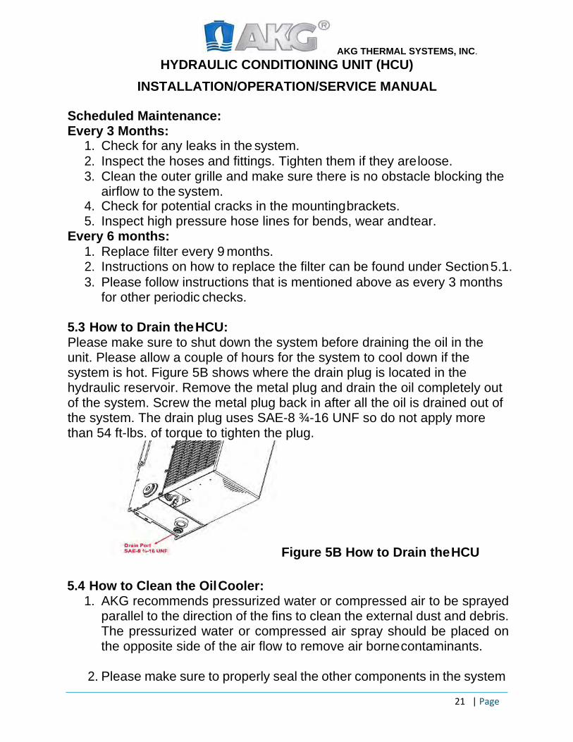
for other periodic checks. 5.3 How to Drain the HCU: Please make sure to shut down the system before draining the oil in the unit. Please allow a couple of hours for the system to cool down if the system is hot. Figure 5B shows where the drain plug is located in the hydraulic reservoir. Remove the metal plug and drain the oil completely out of the system. Screw the metal plug back in after all the oil is drained out of the system. The drain plug uses SAE-8 ¾-16 UNF so do not apply more than 54 ft-lbs. of torque to tighten the plug.
Figure 5B How to Drain the HCU
5.4 How to Clean the Oil Cooler: 1. AKG recommends pressurized water or compressed air to be sprayed
parallel to the direction of the fins to clean the external dust and debris. The pressurized water or compressed air spray should be placed on the opposite side of the air flow to remove air borne contaminants.
2. Please make sure to properly seal the other components in the system
AKG THERMAL SYSTEMS, INC. HYDRAULIC CONDITIONING UNIT (HCU)
INSTALLATION/OPERATION/SERVICE MANUAL
22 | Page
like the electronic controls, fans and motors etc. before cleaning the cooler. Most of the electronic controls like the fans etc. have a minimum rating of IP67.
3. For internal cleaning, please flush the cooler with anti-freeze solution
to get rid of the internal contaminants.
4. For both internal and external cleaning, it is the responsibility of the authorized personnel to use compatible fluids that work well with metals like Aluminum. Otherwise, it leads to cooler corrosion.

AKG THERMAL SYSTEMS, INC. HYDRAULIC CONDITIONING UNIT (HCU)
INSTALLATION/OPERATION/SERVICE MANUAL
23 | Page
6. Troubleshooting: Problem Possible Cause Solution
Overheating Fan not operating Cooler covered with debris/dust
Excessive flow through HCU Hydraulic motor slip or leakage Relief Valve not properly set Check flow control valve setting
Check fan wiring, fuse/ hose connections Clean air rows in the cooler for air to pass through Max flow rate of 35gpm Repair unit or check flow Adjust setting using wrench Remove additional flow control valves or restriction
Noise/ Hydraulic Vibration
Pump Cavitation Check Oil level, hose size, remove 90 degree fittings Check for leaks, tighten fittings, seals etc. Check relief valve setting Check pump position is higher than the tank Reduce pump speed
Oil Condition
Oil discoloration Check for leaks in fittings/hoses Check sources of water or contaminants entering the system Drain and replace oil
High pressure
Oversized or undersized pump Re-size the application Check hose size Reduce speed Repair or replace pump seals
Inconsistent Flow
Air bubbles Inconsistent PTO Output Low Oil in the system
Check leaks and bleed system Check for foaming or bubbles Check PTO operation Add oil ; check for leaks; Install low fluid level sensor
AKG THERMAL SYSTEMS, INC.
HYDRAULIC CONDITIONING UNIT INSTALLATION/OPERATION/SERVICE MANUAL
24 |Page
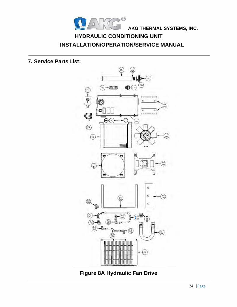
7. Service Parts List:
Figure 8A Hydraulic Fan Drive
25 |Page
AKG THERMAL SYSTEMS, INC.
HYDRAULIC CONDITIONING UNIT INSTALLATION/OPERATION/SERVICE MANUAL
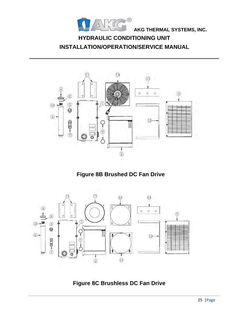
Figure 8C Brushless DC Fan Drive
Figure 8B Brushed DC Fan Drive
26 |Page
AKG THERMAL SYSTEMS, INC.
HYDRAULIC CONDITIONING UNIT INSTALLATION/OPERATION/SERVICE MANUAL
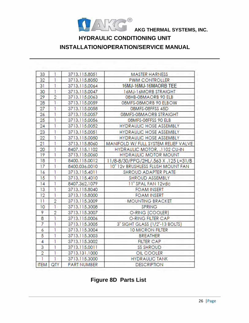
Figure 8D Parts List
27 |Page
AKG THERMAL SYSTEMS, INC.
HYDRAULIC CONDITIONING UNIT INSTALLATION/OPERATION/SERVICE MANUAL
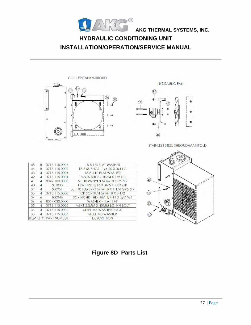
Figure 8D Parts List

28 |Page
AKG THERMAL SYSTEMS, INC.
HYDRAULIC CONDITIONING UNIT INSTALLATION/OPERATION/SERVICE MANUAL
8. Warranty and Returns: All heat transfer products manufactured by AKG Thermal Systems, Inc. are guaranteed against defective material or workmanship for one year of service after purchase by validated end user or 2000 hours service, whichever comes first. Warranty will not apply after 18 months from original ship date from AKG Thermal Systems, Inc. Warranty for components such as fans, motors, and other components when used on an AKG Thermal Systems, Inc. product will be provided by component manufacturer. Any product alleged defective under the warranty period must be returned to AKG Thermal Systems, Inc. unless otherwise specified by AKG Thermal Systems, Inc. Transportation charges are to be prepaid by the customer, unless previously agreed by AKG Thermal Systems, Inc. Warranty consideration is subject to factory inspection. AKG Thermal Systems Inc. is not responsible or liable for products damaged through carelessness or abuse. Careful inspection of products should be made by the customer before returning to AKG Thermal Systems, Inc. for warranty. If factory inspection proves any parts defective, repair or replacement of defective parts will be made without charge to the customer. Transportation charges will be prepaid for returning product back to the customer. Liability under this guarantee is limited to the repair or replacement of the defective parts, and shall in no event include consequential damages of any nature. AKG THERMAL SYSTEMS, INC WARRANTY IS "AS IS" AND WILL BE BOUND BY NO OTHER WARRANTY, EXPRESSED OR IMPLIED, EXCEPT THOSE HEREIN SET FORTH. Any attempt at local repairs automatically cancels this warranty. Returned products must be properly packaged. Adjustments cannot be made on any returned product which is damaged in transit due to poor packaging, and a charge will be made to cover cost of repair. If after factory inspection, product is found not to be defective, an inspection and packaging charge will be made and return freight is not prepaid.

29 |Page
AKG THERMAL SYSTEMS, INC.
HYDRAULIC CONDITIONING UNIT INSTALLATION/OPERATION/SERVICE MANUAL
9. Contact Us
Phone: 919-563-4871
Email: [email protected]
Office Hours: 8am-5pm EST
Address: 7315 Oakwood Street Extension, Mebane, NC-27514 For more information about our company/product, please visit www.akgts.com
For distributor information please visit www.akgts.com/distributors/
AKG THERMAL SYSTEMS, INC.
HYDRAULIC CONDITIONING UNIT INSTALLATION/OPERATION/SERVICE MANUAL
30 | Page
Vibration Testing: AKG’s HCU units are specifically designed for the on-highway market so vibration tests were performed and executed to verify the performance characteristics of the HCU unit in environmental conditions representative of those which may be encountered during transport and operation of the equipment.
The vibration tests were performed in 2019 in accordance to Military standards (MIL-STD) and our units successfully completed the vibration, shock testing representing a vibration profile corresponding to 144,000 miles transportation on U.S. Highways in an on-highway t r uck .
The tests characteristics include 3 axis, accelerated frequency with rms values of 1.04, 0.20 and 0.74g and frequencies ranging from 10 to 500Hz.
The measured values were within the normal expected distribution and steps were taken to identify the weakest points in the unit to overcome failure during the product life-cycle.
AKG does not offer vibration isolators as part of the HCU. Please consult factory for vibration isolation mounts if needed or AKG can assist customers by specifying the right isolation mounts based on the customer request and depending on the type of application.
AKG THERMAL SYSTEMS, INC.
HYDRAULIC CONDITIONING UNIT INSTALLATION/OPERATION/SERVICE MANUAL
31 |Page
Tips:
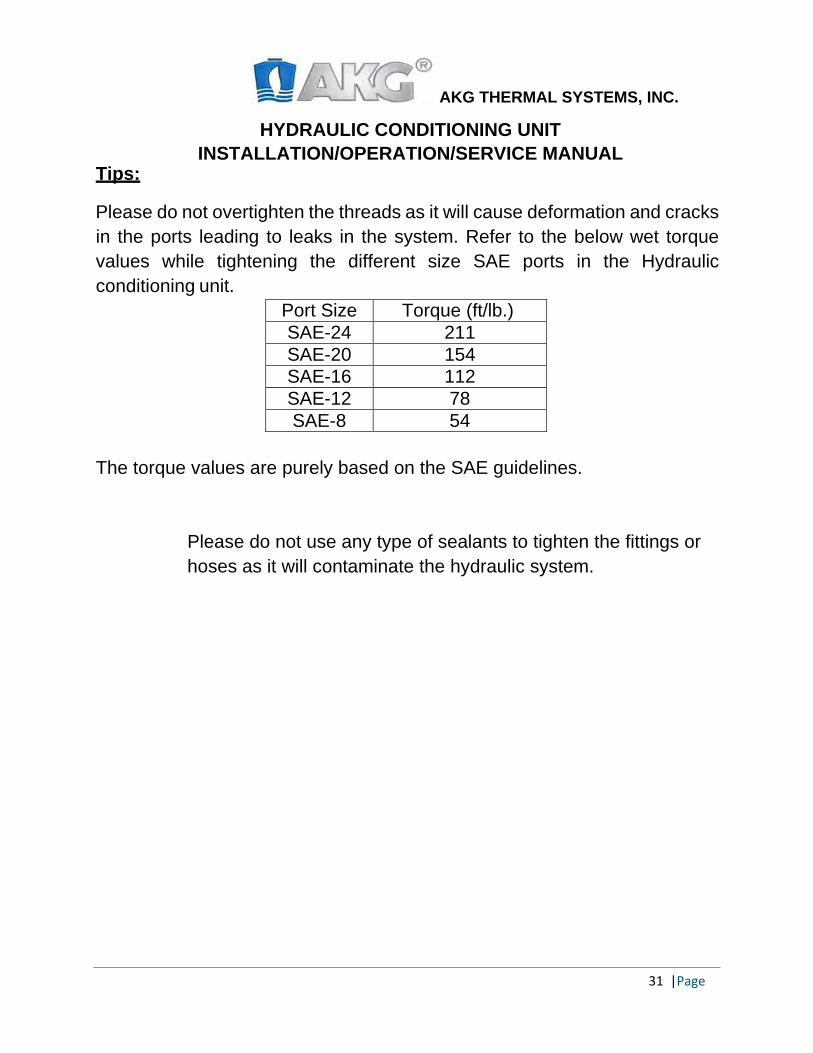
Please do not overtighten the threads as it will cause deformation and cracks in the ports leading to leaks in the system. Refer to the below wet torque values while tightening the different size SAE ports in the Hydraulic conditioning unit.
Port Size Torque (ft/lb.) SAE-24 211 SAE-20 154 SAE-16 112 SAE-12 78 SAE-8 54
The torque values are purely based on the SAE guidelines.
Please do not use any type of sealants to tighten the fittings or hoses as it will contaminate the hydraulic system.
AKG THERMAL SYSTEMS, INC.
HYDRAULIC CONDITIONING UNIT INSTALLATION/OPERATION/SERVICE MANUAL
32 |Page
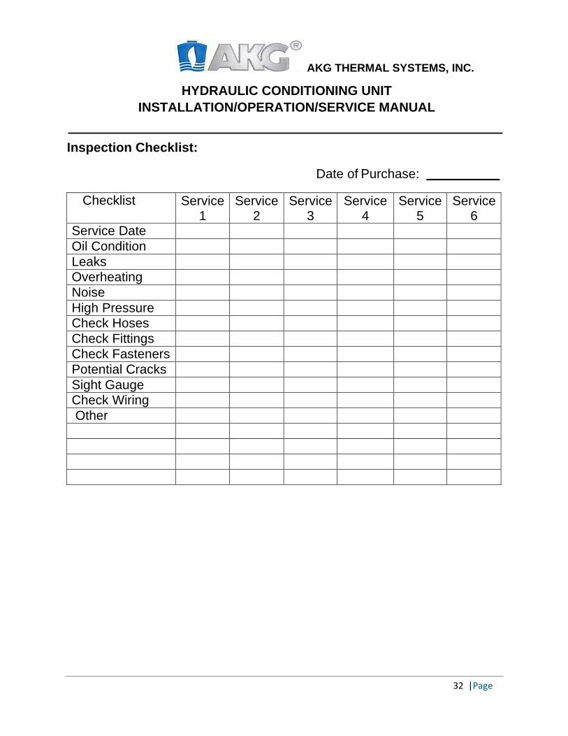
Inspection Checklist:
Date of Purchase:
Checklist Service 1
Service 2
Service 3
Service 4
Service 5
Service 6
Service Date Oil Condition Leaks Overheating Noise High Pressure Check Hoses Check Fittings Check Fasteners Potential Cracks Sight Gauge Check Wiring Other
AKG THERMAL SYSTEMS, INC.
HYDRAULIC CONDITIONING UNIT INSTALLATION/OPERATION/SERVICE MANUAL
NOTES
33| Page Version 9; 03/24/20; VV


