Hydraulic Breaker Owner’s Manual
215
Owner’s Manual BXR SERIES BXR50, BXR65, BXR85, BXR100, BXR120, BXR160 Operation and Parts Hydraulic Breaker 150-2086
Transcript of Hydraulic Breaker Owner’s Manual

Owner’s Manual
BXR SERIES BXR50, BXR65, BXR85, BXR100, BXR120, BXR160Operation and Parts
Hydraulic Breaker
150-2086

Introduction 1To our customer
HYDRAULIC BREAKER OWNER’S MANUAL P/N 150-2086 BREAKER TECHNOLOGY
BXR SERIES
IntroductionTo our customerThank you for purchasing a Breaker Technology (BTI) product for your application. At BTI, we pride ourselves in the equipment we manufacture and distribute.BTI has led the way providing equipment and services for construction, aggregate and mining industries for over 50 years. Technology plays a critical role in the company’s continued success. BTI enjoys a reputation for engineering products with the most advanced technologies, yet the resulting systems are remarkably easy to use.At BTI we believe our product is the industry standard, without exception. Meticulous care has been taken to ensure that this product will meet rigorous product requirements. Using up-to-date CAD modelling software, complemented with !nite element analysis, you can be satis!ed that our product will meet and exceed your prerequisites. BTI has successfully registered our Thornbury facilities as ISO 9001:2008 compliant and to ISO 14001:2004, which is an internationally recognized environmental management system. As always, BTI is committed to continuous improvements translated into positive action. We feel fortunate to say that our team consists of seasoned, long-term, dedicated employees. They are able to respond quickly from our strategically located sales and service locations to any questions you may have.
Eastern USA
Phone (440) 248-7168 | Fax: (440) 248-8645
30625 Solon Industrial Parkway | Solon, OH 44139
Western USA & Mexico
Phone (951) 369-0878 | Fax: (951) 369-8281
3453 Durahart Street | Riverside, CA 92507
Canada & International
Phone (519) 599-2015 | (866) BTI-PART [284-7278] | Fax: (519) 599-6803
35 Elgin Street | P.O. Box 130 | Thornbury, Ontario, Canada N0H 2P0
Document P/N 150-2086 Rev 3 01/2013
www.rockbreaker.com

Introduction2Foreword
BREAKER TECHNOLOGY P/N 150-2086 HYDRAULIC BREAKER OWNER’S MANUAL
BXR SERIES
10595
ForewordThis book is intended as a guide to the use and maintenance of the BTI BXR Series Hydraulic Breakers. Keep it with the operator at all times.Replace it immediately if it becomes lost.The design of the BXR Series of Hydraulic Breakers produces stable high-speed percussion, and exceptional value and durability for all construction, demolition, and rock breaking requirements. BTI BXR Series Hydraulic Breakers use sophisticated technology to produce a simple design. Field-proven and customer-sanctioned BTI breakers are enthusiastically accepted as the standard for the industries they serve.Some typical applications are:
• Construction • Demolition • Recycling • Mining • Quarrying • Trenching • Tunneling

Introduction 3Contents
HYDRAULIC BREAKER OWNER’S MANUAL P/N 150-2086 BREAKER TECHNOLOGY
BXR SERIES
ContentsIntroduction .......................................................... 1
To our customer ..................................................................................... 1Foreword .................................................................................................. 2
General Information ............................................. 7Product Serial Number ........................................................................ 7Structure and Design .......................................................................... 8
Bare Breaker Exploded View ................................................................. 9Features and Bene!ts ........................................................................10Simpli!ed Principle of Operation ..................................................12
(A) Piston Upward Movement ............................................................12(B) Activating Pilot Valve On ...............................................................12(C) Pilot Valve ON ....................................................................................12(D) Piston Downward Movement – Impact ...................................13(E) Piston Upward Movement.............................................................13(F) Pilot Valve OFF ...................................................................................13Main Control Valve OFF ........................................................................14Oil Regeneration System ......................................................................14
How the Tool Breaks Rock ................................................................14Contact–Initial Compression Stress Wave ......................................14Recoil–Re"ected Stress Wave .............................................................14Blank-!ring ................................................................................................15
Anti-blank Firing ..................................................................................15High/low Speed Selector Valve ......................................................16
Long stroke / Slow speed (factory setting) ....................................16Short stroke / High speed (requires oil supply) ...........................16
Sizing the Hydraulic Breaker ...........................................................17Based on Carrier Weight .......................................................................17Based on Material Type and Hardness ............................................18Based on the Type of Work ..................................................................18Breaker Production Rates .....................................................................19
Recommended Hydraulic Oils ........................................................20Other Hydraulic Oils ...............................................................................21Arctic Grade Oils ......................................................................................23 Oil is Too Thick or Too Thin ..................................................................24Hydraulic Oil Purity ................................................................................24Hydraulic Oil Cooling .............................................................................25
Safety Rules ......................................................... 27Safety Alert Symbol ...........................................................................27
Signal Words .............................................................................................27General Safety Precautions .............................................................28
Practice Safe Maintenance ..................................................................28Precautions for Working on Hydraulic Systems ...........................29Precautions for Handling Hydraulic Oil...........................................30Work Site Precautions ...........................................................................30Fire Prevention .........................................................................................31Welding and Grinding Work ...............................................................31Work on Painted Surfaces ....................................................................32Rubber and Plastics ................................................................................32
Hazard Alerts ........................................................................................32Transporting Safety Precautions ...................................................36
Installation .......................................................... 37General....................................................................................................37Mounting the Breaker .......................................................................38Setting Flow and Pressure ...............................................................38
Setting the Flow ......................................................................................38Setting the Relief pressure ..................................................................38
Start-up ...................................................................................................39Typical hydraulic Circuits ..................................................................39
Carrier with Auxiliary Hydraulic Circuit ...........................................39Carrier without Auxiliary Hydraulic Circuit ....................................40
Operation ............................................................ 41Suggestions for E#cient Operation .............................................41
End of Shift ................................................................................................42Improper Use of Breaker ...................................................................42
Blank Firing................................................................................................43Breaking Oversize Material ..............................................................44Trenching and Excavation ................................................................44Breaking Concrete ..............................................................................44Breaking on a Grizzly .........................................................................45Guide to Tool Choice ..........................................................................45Underwater Operation ......................................................................46
Preparations for Underwater Operation.........................................46Air Pressure for Underwater Operation ..........................................47Operating the Breaker Underwater ..................................................47
Cold Weather Operation ...................................................................48Cold Weather Starting ...........................................................................48Hydraulic System Warm-up Procedure ...........................................48Breaker Warm-up Procedure ...............................................................48Grease for Cold Weather Operation .................................................49
High/Low Speed Selector Valve .....................................................49Locking the Valve in High or Low Speed Mode ...........................49
Maintenance ....................................................... 51Greasing the Breaker .........................................................................51Automatic Greasing Systems ..........................................................51
General .......................................................................................................51Comparison of Automatic Lubrication Systems to Manual Lubrication ................................................................................................52
Changing the Breaker Tool ..............................................................52Tool and Front Tool Bushing Clearance...........................................52Permissible Nominal Minimum and Maximum Diameters for Wear Bushings and Breaker Tool .......................................................53Tool Removal ............................................................................................53Tool Installation .......................................................................................54
Cushion Chamber Gas Pressure – Checking .............................54Cushion Chamber Gas Pressure – Adjusting .............................56
Increasing the Pressure .........................................................................56Decreasing the Pressure .......................................................................56Removing the Gauge and Hose .........................................................56
Accumulator Gas Pressure – Checking ........................................57Accumulator Gas Pressure – Adjusting .......................................58
Increasing the Pressure .........................................................................58Decreasing the Pressure .......................................................................58Removing the Gauge and Hose .........................................................58
Nitrogen Charging Pressure versus Ambient Temperature .59Maintenance Schedule .....................................................................60
Pre Shift ......................................................................................................60Every 2 Hours ............................................................................................60Every 8 Hours – Daily .............................................................................60Every 50 Hours – Weekly ......................................................................60Every 100 Hours .......................................................................................61Every 500 Hours .......................................................................................61Every 1000 Hours or Yearly ..................................................................61

Introduction4Contents
BREAKER TECHNOLOGY P/N 150-2086 HYDRAULIC BREAKER OWNER’S MANUAL
BXR SERIES
Service ................................................................. 63Safety Warnings ...................................................................................63Breaker Disassembly ..........................................................................64
Removing Breaker Body from Housing ..........................................65Breaker Body Disassembly ...............................................................67
Rear head Removal ................................................................................67Accumulator Removal ...........................................................................68Diaphragm Replacement .....................................................................68Accumulator Assembly .........................................................................69Control Valve Removal and Disassembly .......................................69Control Valve Inspection ......................................................................70Control Valve Assembly ........................................................................71Piston Removal ........................................................................................72Cylinder Removal ....................................................................................73Cylinder Inspection ................................................................................73Cylinder Clean-up ...................................................................................74Maximum Clearances Between Cylinder and Piston .................75Seal Bushing Inspection .......................................................................76Tool Bushing Removal ...........................................................................76
Breaker Body Assembly ....................................................................77Tool Bushing Installation ......................................................................77Tie Rod Installation .................................................................................78Cylinder Installation ..............................................................................79Seal Bushing – Re-sealing ....................................................................79Piston Installation ...................................................................................80Inspect Gas and Air Valve .....................................................................80Control Valve Installation .....................................................................81Accumulator Installation ......................................................................81Charging the Accumulator ..................................................................82Installing the Rear head ........................................................................83Charging the Cushion Chamber ........................................................84
Breaker Assembly ................................................................................84Nylon Support Pads ...............................................................................85Determining Shims Required .............................................................85Upper and lower Isolator Limits ........................................................87Installing the Breaker Body Into the Housing ...............................88Start-up .......................................................................................................90
Troubleshooting Guide ...................................... 91Oil Leakage ............................................................................................91Hydraulic Breaker ................................................................................92Breaker Tool ...........................................................................................97
Normal Breaker Tool Wear....................................................................97Breaker Tool Fatigue Failures ..........................................................97
Cause and E$ect of Fatigue .................................................................98Other Causes of Increased Tool fatigue Stress .............................98
Area of Typical Tool Failures ............................................................99Guide to Warranty Claims ....................................................................99Mushrooming........................................................................................ 100Steel Defect Failure ............................................................................. 100
Removal and Storage ....................................... 101Short-term Storage ......................................................................... 101Long-term Storage .......................................................................... 101
Breaker Stored Lying Down.............................................................. 101Initial Start-up after Storage ........................................................ 102
Breaker Stored Standing Up ............................................................ 102
Speci!cations .................................................... 104Model BXR50 ..................................................................................... 104
BXR50 Mounting Plate ....................................................................... 105
Model BXR65 ..................................................................................... 106BXR65 Mounting Plate ....................................................................... 107
Model BXR85 ..................................................................................... 108BXR85 Mounting Plate ....................................................................... 109
Model BXR100 ................................................................................... 110BXR100 Mounting Plate ..................................................................... 111
Model BXR120 ................................................................................... 112BXR120 Mounting Plate ..................................................................... 113
Model BXR160 ................................................................................... 114BXR160 Mounting Plate ..................................................................... 115
Torque Speci!cations ....................................... 116BXR50 ................................................................................................... 116BXR65 ................................................................................................... 118BXR85 ................................................................................................... 120BXR100 ................................................................................................. 122BXR120 ................................................................................................. 124BXR160 ................................................................................................. 126
Breaker Parts ..................................................... 129BXR50 ................................................................................................... 129
Main Breaker Assembly ..................................................................... 129Bare Breaker ........................................................................................... 130Control Valve.......................................................................................... 132Accumulator Assembly ...................................................................... 133Master Seal Kit ....................................................................................... 134Control Valve Seal Kit .......................................................................... 135Internal Seal Kit ..................................................................................... 136Accumulator Seal Kit........................................................................... 137
BXR65 ................................................................................................... 139Main Breaker Assembly ..................................................................... 139Bare Breaker ........................................................................................... 140Control Valve.......................................................................................... 142Accumulator Assembly ...................................................................... 143Master Seal Kit ....................................................................................... 144Control Valve Seal Kit .......................................................................... 145Internal Seal Kit ..................................................................................... 146Accumulator Seal Kit........................................................................... 147
BXR85 ................................................................................................... 149Main Breaker Assembly ..................................................................... 149Bare Breaker ........................................................................................... 150Control Valve.......................................................................................... 152Accumulator Assembly ...................................................................... 153Master Seal Kit ....................................................................................... 154Control Valve Seal Kit .......................................................................... 156Internal Seal Kit ..................................................................................... 157Accumulator Seal Kit........................................................................... 159
BXR100 ................................................................................................. 161Main Breaker Assembly ..................................................................... 161Bare Breaker .......................................................................................... 162Control Valve.......................................................................................... 164Accumulator Assembly ...................................................................... 165Master Seal Kit ....................................................................................... 166Control Valve Seal Kit .......................................................................... 168Internal Seal Kit ..................................................................................... 169Accumulator Seal Kit........................................................................... 171

Introduction 5Contents
HYDRAULIC BREAKER OWNER’S MANUAL P/N 150-2086 BREAKER TECHNOLOGY
BXR SERIES
BXR120 ................................................................................................. 173Main Breaker Assembly ..................................................................... 173Bare Breaker ........................................................................................... 174Control Valve.......................................................................................... 176Accumulator Assembly ...................................................................... 177Master Seal Kit ....................................................................................... 178Control Valve Seal Kit .......................................................................... 179Internal Seal Kit ..................................................................................... 180Accumulator Seal Kit........................................................................... 181
BXR160 ................................................................................................. 183Main Breaker Assembly ..................................................................... 183Bare Breaker ........................................................................................... 184Control Valve.......................................................................................... 186Accumulator Assembly ...................................................................... 187Master Seal Kit ....................................................................................... 188Control Valve Seal Kit .......................................................................... 189Internal Seal Kit ..................................................................................... 190Accumulator Seal Kit........................................................................... 191
Stroke Adjuster Assembly ............................................................ 192Air Valve Assembly ........................................................................... 193Regeneration Valve ......................................................................... 194BXR Auto-Lube System .................................................................. 196BXR50 Auto Grease System .......................................................... 198BXR65 Auto Grease System .......................................................... 199BXR85 Auto Grease System .......................................................... 200BXR100 Auto Grease System ........................................................ 201BXR120 Auto Grease System ........................................................ 202BXR160 Auto Grease System ........................................................ 203
Warranty ............................................................ 205Hydraulic Breaker Warranty Policy ............................................. 205
Reference Information ..................................... 206Hardness of Rock ............................................................................. 206Viscosity Conversion Table............................................................ 207Fluid Grade Systems ........................................................................ 208Box Housing Measurement Data Sheet ................................... 209Service Report ................................................................................... 210Receiving Inspection Report ........................................................ 211Delivery Report ................................................................................. 212Conversion factors ........................................................................... 213

NOTES
6
BREAKER TECHNOLOGY P/N 150-2086 HYDRAULIC BREAKER OWNER’S MANUAL
BXR SERIES
General Information 7Product Serial Number
HYDRAULIC BREAKER OWNER’S MANUAL P/N 150-2086 BREAKER TECHNOLOGY
BXR SERIES
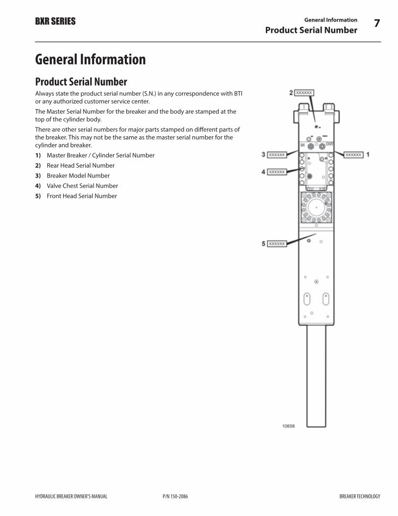
General InformationProduct Serial NumberAlways state the product serial number (S.N.) in any correspondence with BTI or any authorized customer service center.The Master Serial Number for the breaker and the body are stamped at the top of the cylinder body.There are other serial numbers for major parts stamped on di$erent parts of the breaker. This may not be the same as the master serial number for the cylinder and breaker.1) Master Breaker / Cylinder Serial Number2) Rear Head Serial Number3) Breaker Model Number4) Valve Chest Serial Number5) Front Head Serial Number

General Information8Structure and Design
BREAKER TECHNOLOGY P/N 150-2086 HYDRAULIC BREAKER OWNER’S MANUAL
BXR SERIES
Structure and Design The BXR hydraulic breaker represents the state of the art in rock breaking technology. The BTI hydraulic breaker delivers rock-breaking power with the minimum of parts.
Four tie rods are assembled to hold the cylinder and rear head together with the front head.
A control valve is assembled to the cylinder and regulates piston movement.
The cylinder contains a moving piston that strikes the tool.
Retainer pins inside the front head prevent the tool from coming out.

General Information 9Structure and Design
HYDRAULIC BREAKER OWNER’S MANUAL P/N 150-2086 BREAKER TECHNOLOGY
BXR SERIES
Bare Breaker Exploded ViewNOTE: Drawing is intended as a reference only. Consult Parts Section of this manual for information on a speci!c model.

General Information10Features and Bene!ts
BREAKER TECHNOLOGY P/N 150-2086 HYDRAULIC BREAKER OWNER’S MANUAL
BXR SERIES
Features and Bene!ts1) Overall system designed for harsh, continuous duty use in demanding
rock-breaking applications.2) High volume nitrogen chamber – reduces pressure "uctuations in the
hydraulic circuit and provides stable piston acceleration, while providing consistent blow energy and recoil energy absorption.
3) E$ective energy recovery system captures recoil energy for use on the next blow – increasing breaker e#ciency, providing more power to the target material resulting in higher production rates.
4) Precise tolerances between the piston and cylinder – provide high breaker e#ciencies, blow rates, and power.
5) Extra-long stroke piston – provides stable piston acceleration and e#cient absorption of recoil energy for reliable operation in all breaking situations. The extra long stroke and heavy piston design improves the power-to-weight ratio of the breaker providing the widest carrier range and power available in the energy class.
6) Large tool diameter – provides excellent raking strength and transmission of energy from the piston to the tool and target material.
7) A high-pressure accumulator reduces any potential pressure spikes produced by the large piston and energy recovery system.
8) Remote air breather located at the top of the breaker – provides clean air to impact chamber, and allows for convenient hook up of compressed air for underwater applications.
9) Remote greasing port, located near the top of the breaker, close to the main hydraulic hose connections – provides a convenient interface to carrier-mounted remote greasing systems.
10) Unique teardrop washer and hardened stainless steel “Nordlock” washers located at the top of the tie rod – eliminates the loss of the tie rod torque due to bolts loosening from vibration.
11) Oversized, high tensile alloy steel tie-rods equipped with multiple vibration dampeners – reduce tie-rod stress and vibration increasing breaker life and dependability.
12) The design concept provides for stronger short tie-rods reducing tie rod fatigue from vibration.
13) Oversized heliserts located at the lower end of the tie-rods in the front-head – provide excellent load transmission between the components reducing fatigue.
14) Oversized upper and lower shock absorbing isolators reduce vibration feedback to the carrier.
15) Large access panels allow routine maintenance to the accumulator, control valve body and hose connections without removing the breaker from the box housing.
16) Contoured, composite, high-pressure accumulator bladder design-maximizes bladder life.
17) Flat top tool design – allows for maximum levels of energy transfer.18) Oversized, full-length oval retaining pins - provide excellent resistance to
blank !re with an expansive load bearing area on the front head.19) Thick abrasion resistant plate and rock-claws at the breaker nose –
prolong box housing life and improve material handling.

General Information 11Features and Bene!ts
HYDRAULIC BREAKER OWNER’S MANUAL P/N 150-2086 BREAKER TECHNOLOGY
BXR SERIES
20) Optional severe duty package with additional abrasion resistant plate at the nose and wear bars along the side of the breaker withstand the toughest wear conditions.
21) Suspended breaker design – reduces breaker noise for a quieter system and reduces vibration to the carrier.
22) BTI’s exclusive front head restraint system within the housing tightly guides the front head within the box-housing - reduces loading to the tie rods and the upper portion of the breaker by eliminating load transfer to the upper half of the breaker.
23) Anti-blank !re interlock - prevents blank !re of tool, reducing shock loading to the retaining pins and front head.
24) Rounded thread pro!le on the upper tie rod threads provides better load distributions and reduces stress to tie rod nuts, eliminating tie rod failure.

General Information12Simpli!ed Principle of Operation
BREAKER TECHNOLOGY P/N 150-2086 HYDRAULIC BREAKER OWNER’S MANUAL
BXR SERIES
Simpli!ed Principle of OperationBXR Series hydraulic breakers have a simple design. The following diagrams illustrate the stages of movement as the breaker cycles in operation.
(A) Piston Upward MovementPressurized oil enters cylinder chamber (1), pilot chamber (13), and control valve chamber (16), the high/low speed selector valve is pushed to the right (low speed condition) by low-pressure. The pressurized oil in pilot chamber (13) pushes the pilot valve to the right side.The pressurized oil in control valve chamber (16) pushes the control valve spool down. The pressurized oil in cylinder chamber (1) lifts the piston up compressing gas in nitrogen chamber (6).At this time, the oil on the opposite side of the piston in cylinder chamber (5) "ows out through the control valve chamber (15).
(B) Activating Pilot Valve OnWhen the oil from the lower piston "ange reaches cylinder chamber (3), pressurized oil "ows through the high/low speed selector valve chamber (7) working against pilot valve chamber (10). Once the pressurized oil activates pilot chamber (10), pilot chambers (10) and (13) equalize pressure and due to the surface area di$erence, the pilot control valve spool is pushed to the left.
(C) Pilot Valve ONWhen the pilot valve spool is pushed to the left (due to the surface area di$erence in the pilot valve) the pressurized oil working on pilot chamber (13) allows oil to pass through pilot chamber (12), activating the lower section of control valve chamber (14). When pressurized oil activates control valve chamber (14), chamber (14) and (16) equalize pressure (due to surface area di$erence) and the control valve spool moves up.

General Information 13Simpli!ed Principle of Operation
HYDRAULIC BREAKER OWNER’S MANUAL P/N 150-2086 BREAKER TECHNOLOGY
BXR SERIES
(D) Piston Downward Movement – ImpactWhen the control valve spool moves up, the pressurized oil in control valve chamber (16) moves through the control valve into cylinder chamber (5) pushing the piston down. The compressed gas in the nitrogen chamber (6) assists in the downward force on the piston. The piston hits the tool.
(E) Piston Upward MovementAs the piston’s large diameter groove reaches pilot chamber (10) the pressurized oil "ows out cylinder chambers (3) and (4). Pilot chamber (10) becomes low-pressure and because pilot chamber (13) is activated by pressurized oil, the pilot valve spool is pushed to the right.
(F) Pilot Valve OFFWhen the pilot valve spool is pushed right, it activates the lower "ange area of the control valve chamber (14), this pressurized oil passes through the pilot valve groove, draining the pilot chambers (11) and (12). When control valve chamber (14) becomes low-pressure, the control valve chamber (16) continues to be a$ected by pressurized oil pushing the control valve spool down.

General Information14Simpli!ed Principle of Operation
BREAKER TECHNOLOGY P/N 150-2086 HYDRAULIC BREAKER OWNER’S MANUAL
BXR SERIES
Main Control Valve OFFWhen the control valve spool is pushed down, the control valve chamber (15) and the inside of the control valve connect, reducing pressure inside the control valve and in the upper section of the cylinder chamber. Pressurized oil enters the lower section of the cylinder chamber (1) pushing the piston up.
The above cycle repeats, resulting in continuous blows.
Oil Regeneration SystemThe timing (delayed circuit) for the pilot valve to switch over delays the switch over for the control valve. When the piston hits the tool, the reaction lifts (bounces) the piston and the oil in the upper "ange area of piston chamber (5) passes through the control valve to the lower "ange area of the piston chamber (1). This system reuses the pressurized oil to increase the blows per minute to improve breaker e#ciency.
How the Tool Breaks RockThe following paragraphs describe what happens to break rock when the piston strikes the tool.
Contact–Initial Compression Stress WaveWhen the piston (1) strikes the top of the tool (2), it sends a compressive stress wave (3) down to the working end of the tool. If the tool is touching a rock, this energy/force (compressive stress wave) travels through the tool directly into the rock (4), fracturing it.
Recoil–Re"ected Stress WaveImmediately following the initial compressive stress wave, a re"ected stress wave is formed (5), which travels back up the tool, ‘bouncing’ the piston up o$ the top of the tool. This cycle of compressive and tensile stresses "owing up and down the tool is repeated with each piston blow
General Information 15Anti-blank Firing
HYDRAULIC BREAKER OWNER’S MANUAL P/N 150-2086 BREAKER TECHNOLOGY
BXR SERIES
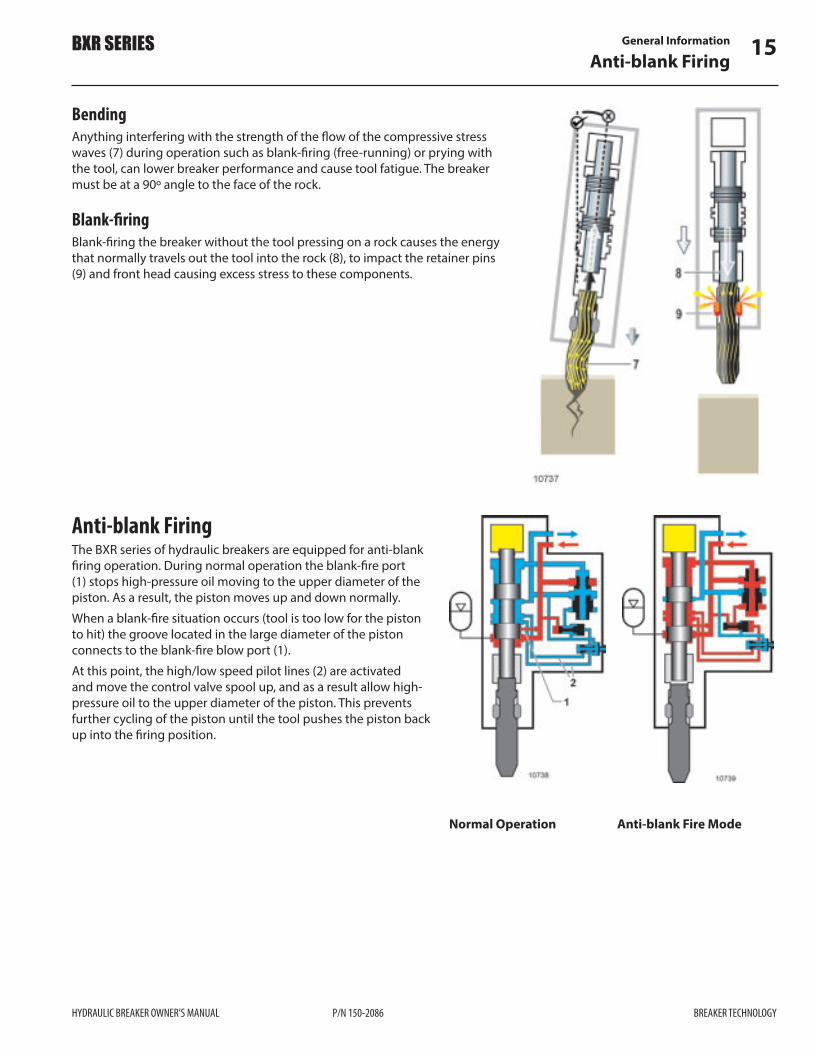
Bending Anything interfering with the strength of the "ow of the compressive stress waves (7) during operation such as blank-!ring (free-running) or prying with the tool, can lower breaker performance and cause tool fatigue. The breaker must be at a 90º angle to the face of the rock.
Blank-!ringBlank-!ring the breaker without the tool pressing on a rock causes the energy that normally travels out the tool into the rock (8), to impact the retainer pins (9) and front head causing excess stress to these components.
Anti-blank FiringThe BXR series of hydraulic breakers are equipped for anti-blank !ring operation. During normal operation the blank-!re port (1) stops high-pressure oil moving to the upper diameter of the piston. As a result, the piston moves up and down normally.When a blank-!re situation occurs (tool is too low for the piston to hit) the groove located in the large diameter of the piston connects to the blank-!re blow port (1).At this point, the high/low speed pilot lines (2) are activated and move the control valve spool up, and as a result allow high-pressure oil to the upper diameter of the piston. This prevents further cycling of the piston until the tool pushes the piston back up into the !ring position.
Normal Operation Anti-blank Fire Mode

General Information16High/low Speed Selector Valve
BREAKER TECHNOLOGY P/N 150-2086 HYDRAULIC BREAKER OWNER’S MANUAL
BXR SERIES
High/low Speed Selector ValveThe BXR series hydraulic breaker has an internal two-speed selector valve that can be remotely actuated by the operator. NOTE: Connecting a minimum oil supply of 400 psi (27 bar) controlled by an on/o$ valve to the two-speed valve connection port, will allow the operator to manually shift the breaker between long and short stroke modes.The longer stroke provides a slower speed and a higher power mode. The shorter stroke provides a higher speed and a lower power mode.
Long stroke / Slow speed (factory setting)The breaker will operate in the standard mode with no hydraulic connection to the two-speed valve.Venting hydraulic oil from the two speed valve to tank, shifts the valve spool to the right due to the back-pressure within the breaker. As a result, the high-speed pilot line (2) will be blocked triggering the low-speed pilot line (3) allowing the piston to operate in long-stroke mode.The piston retracts up to the stroke signal cavity shifting the main valve spool; hydraulic pressure is sent to the two-speed valve, and the ORG pilot valve. The ORG pilot valve shifts, sending high-pressure oil to the main directional control valve spool. The main valve shifts and forces the piston back down to strike the tool.
1) Long Stroke Cavity2) High-speed Pilot Line3) Low-speed Pilot Line4) Two-speed Valve5) Two-speed Valve Connection Port6) Short Stroke Cavity7) ORG Pilot Valve8) Main Control Valve
Short stroke / High speed (requires oil supply)Remote pilot pressure is required to shift the two-speed valve. By pressurizing the two-speed control valve port, the valve spool is shifted left. This connects the high-speed pilot line (2) and low-speed pilot line (1), triggering the high-speed pilot line (2). This allows the piston to work in the short-stroke mode.The piston retracts up to the stroke signal cavity shifting the main valve spool. A hydraulic pressure signal is generated and passes the two-speed valve to the main directional control valve spool. The main valve shifts and forces the piston back down to strike the tool.See “High/Low Speed Selector Valve” on page 49 for additional information.

General Information 17Sizing the Hydraulic Breaker
HYDRAULIC BREAKER OWNER’S MANUAL P/N 150-2086 BREAKER TECHNOLOGY
BXR SERIES
Sizing the Hydraulic BreakerWhen sizing the breaker to the machine, two key points should be given careful consideration:
• Machine operating weight • Hydraulic system capabilities
With the correct carrier weight, BTI o$ers hydraulic breakers that are designed to break any material that the machine can handle. Sizing the breaker by carrier hydraulics gives the operator a carrier/breaker combination designed to optimize the system e#ciency, thereby reducing heat generation and eliminating power loss.The following steps will result in a well-matched installation. This manual will not cover all types of applications, so for assistance in any unusual situations please contact your BTI representative.
Based on Carrier WeightBy using the Carrier Sizing Chart below, you can narrow your hammer choice. Normally breaker production rate is the most crucial factor when trying to choose a breaker size. It is of great bene!t to do some research and understand your hydraulic system capabilities and the material size and hardness before determining an expected production rate. This rate will also be a$ected by breaking conditions and the operator.
15 20 25 30 35 40 45 50 55 60 65 70 75 80 85 90 100
42 - 81
55 - 100
18-35
19-42
28-48
34-68
Carrier Weight in Tonnes (metric)
Carrier Sizing Chart
BREAKERMODEL
BXR50������IW�OE��������MRXOH�
BXR65������IW�OE��������MRXOH�
BXR85������IW�OE���������MRXOH�
BXR100�������IW�OE���������MRXOH�
BXR160�������IW�OE���������MRXOH�
BXR120�������IW�OE���������MRXOH�
([FDYDWRU10563

General Information18Sizing the Hydraulic Breaker
BREAKER TECHNOLOGY P/N 150-2086 HYDRAULIC BREAKER OWNER’S MANUAL
BXR SERIES
Based on Material Type and HardnessIt is also very important to match the breaker size to the hardness and size of the oversize material.The table below illustrates the relationship of oversize rock and its hardness (compressive strength) to the size of the breaker required.When the rock physical size or hardness exceeds the suggestions below, then it will be necessary to increase the breaker size accordingly.
Material Type and Hardness
Typical Oversize(average)
Compressive Strength(Rock Type)
Breaker Energy Classft•lb joule
1 cu yd and smaller
5,000–10,000 psi(cement grade soft limestone)
1,000 1 350
1 cu yd 10,000–20,000 psi(aggregate grade dolomite, limestone)
2,000 2 700
2 cu yd 20,000–30,000 psi(hard rock to softer granite)
4,000 5 400
3 cu yd 30,000-40,000 psi(very hard rock, granite, trap rock)
5,500 7 500
4 cu yd 30,000-50,000 psi(very hard rock, granite, trap rock)
8,500 11 500
6 cu yd 30,000-60,000 psi(very hard rock, granite, trap rock, iron ore)
10,000 13 600
8 cu yd 30,000-70,000 psi(very hard rock, granite, trap rock, iron ore)
12,000 16 300
10 cu yd and larger
30,000-90,000 psi(very hard rock, granite, trap rock, iron ore)
16,000 21 700
Based on the Type of WorkThe Production Rate is the next important factor to consider in sizing the breaker. Refer to “Breaker Production Rates” on page 19. Most situations call for the largest breaker that your carrier could handle. The largest breaker is therefore the one to choose. The lifting capacity of your machine is then the limiting factor. The carrier machine must be able to safely handle the breaker at any distance out from the machine where you might be working.
Small BreakersSmaller sized breakers up to 1,000 ft•lb class (1 350 joule) are typically used in concrete and other light duty work.
Medium BreakersMedium sized breakers 1,500–4,000 ft•lb class (2 000–5 400 joule) are used in both concrete and rock applications with limitations on the size and amount of material to be broken.
Large BreakersLarger breakers greater than the 4,000 ft•lb class (5 400 joule) are typically used in hard rock, high production applications.

General Information 19Sizing the Hydraulic Breaker
HYDRAULIC BREAKER OWNER’S MANUAL P/N 150-2086 BREAKER TECHNOLOGY
BXR SERIES
Breaking OversizeWhen breaking oversize material, the breaker is expected to break the material down quickly into multiple pieces. This is optimum production. If the operator has to re-position the breaker towards the edge of the rock and gradually downsize the material, the production rate slows down.To assess which breaker will e$ectively handle this application, the size and hardness of the material must be known. For example, if a 4 cubic yard piece of hard rock (20,000 psi or greater) needs to be broken in half, a 7,500 ft•lb or larger breaker is required. If a 2 cubic yard piece of limestone (20,000 psi or less) needs to be broken in half, a 3,000–5,000 ft•lb breaker is required.
TrenchingWhen trenching, the breaker is expected to fracture a solid mass of rock into manageable pieces. The size of the material could be hundreds of cubic yards, and the energy will be quickly absorbed. This is why it is recommended to work from a bench so the rock has somewhere to break out. When trenching in limestone or medium hard rock, use a 3,000–5,000 ft•lb breaker. When working in hard material use a 7,500–10,000 ft•lb breaker, and if high production is critical, a larger breaker would be bene!cial.
Breaker Production RatesThe values shown are non-binding guidelines. They will vary depending on machine, operator and job conditions.
200–340 (153–260) 250–440 (191–336) 200–360 (153–275)
600–800 (459–612)
700–900 (535–688) 250–510 (191–390)
400–650 (306–497) 330–530 (252–405)400–650 (306–497)800–1,000 (612–765)
550–800 (420–612) 400–650 (306–497) 650–900 (497–688)900–1200 (688–917)
490–800 (375–612)650–1,000 (497–765)800–1,100 (612–841)1,000–1,400 (765–1 070)
230–400 (176–306) 300–500 (229–382) 230–500 (176–382)
360–600 (275–459) 300–475 (229–363)
475–600 (363–458)
Production Rate/8 Hour Shift – yd3 (m3)
NON-REINFORCED CONCRETE
REINFORCED CONCRETE
MEDIUM ROCKBREAKERMODEL
HARD ROCK
10564
BXR50������IW�OE��������MRXOH�
BXR65������IW�OE��������MRXOH�
BXR85������IW�OE���������MRXOH�
BXR100�������IW�OE���������MRXOH�
BXR160�������IW�OE���������MRXOH�
BXR120�������IW�OE���������MRXOH�

General Information20Recommended Hydraulic Oils
BREAKER TECHNOLOGY P/N 150-2086 HYDRAULIC BREAKER OWNER’S MANUAL
BXR SERIES
Breaking ConcreteWhen breaking Concrete, the breaker is expected to penetrate the material, allowing it to crack and shake loose from the reinforcing steel. High frequency breakers tend to provide better performance in this application. It is not the energy per blow, but the fast blow rate that destroys the concrete’s structural integrity. On concrete walls, footings and "oors use a 750–1,500 ft•lb breaker. With larger projects consisting of large footings greater then 4 cubic yards, use a 2,000–5,000 ft•lb breaker. The high production demand of bridge and building demolition requires a 7,500–10,000 ft•lb breaker.
Recommended Hydraulic OilsGenerally speaking, the hydraulic oil intended for an excavator (carrier) can be used in the hydraulic breaker. A hydraulic oil with anti-wear, anti-oxidation, anti-foaming, and anti-rust properties is recommended with a Viscosity Index of 150–160. Refer to the table below. Hydraulic oils from di$erent suppliers that fall within the ISO (International Standards Organization) bar graph will have very similar viscosities. However, since working with the hydraulic breaker will heat the oil much more than in excavation work, the viscosity of the oil should be checked.In continuous breaker operation, the temperature of the hydraulic oil stabilizes. This is dependent on ambient temperature, working conditions. In this situation, the viscosity of the hydraulic oil must be 20–45 cSt (2.90–6.20°E).
Recommended Hydraulic Oil
Premium Quality HVI(High Viscosity Index)
Ambient Temperature
** ISO HVI 15
ISO HVI 46
ISO HVI 68
ºFºC
-40-40
-22-30
-4-20
+14-10
+320
+50+10
+68+20
+86+30
+104+40
+122+50
10294
** Warm-up procedure required in low temperatures. Refer to “Cold Weather Operation” on page 48 for special cold weather start-up and operation procedures.
CAUTION!
The breaker must not be operated when the hydraulic oil viscosity is above 800 cSt (114ºE) or below 15 cSt (2,35ºE). Serious damage may occur to the breaker and hydraulic circuit. Ensure procedures outlined in the carrier manual are followed.

General Information 21Recommended Hydraulic Oils
HYDRAULIC BREAKER OWNER’S MANUAL P/N 150-2086 BREAKER TECHNOLOGY
BXR SERIES
Shell Tellus
Mobil
Esso Univis
Petro CanadaHarmony
BP Energol
Texaco Rando
T32
T37
T46
DTE13
DTE15
DTE16
HP32
HP46
AW32
AW46
HVI22
HLP46
HDZ15
HDZ32
HDCZ68
9LVFRVLW\+40°C (104 F)
cSt (E)°
3HUPLWWHG 2SHUDWLQJ7HPSHUDWXUH 5DQJH
Max: 80ºC (176ºF)Min: -20ºC (-4ºF)800 . . . 15 cSt
,GHDO 2SHUDWLQJ7HPSHUDWXUH 5DQJH
40 . . . 20 cSt 3RXU 3RLQW°C (°F)°C (°F)
32 (4,35)
37 (4,95)
46 (6,15)
29 (3,95)
40 (5,35)
58 (7,70)
30 (4,10)
45 (6,00)
30 (4,10)
45 (5,60)
20
50 (6,65)
16 (2,45)
32 (4,35)
65 (8,60)
-15 (5) ...+60 (140)
-10 (14) ... +65 (149)
-5 (23) ...+70 (158)
-20 (-4) ...+62 (144)
-13 (9) ...+72 (162)
-8 (18) ...+80 (176)
-17 (1) ...+60 (140)
-12 (10) ...+75 (167)
-20 (-4) ...+65 (149)
-20 (-4) ...+72 (162)
-30 (-22) ...+57 (135)
-3 (27) ...+72 (162)
-20 (-4) ...+43 (109)
-20 (-4) ...+65 (149)
-9 (16) ...+80 (176)
+35 (95) ...+53 (127)
+40 (140) ...+56 (133)
+42 (108) ...+60 (140)
+32 (90) ...+52 (126)
+40 (104) ...+61 (142)
+48 (118) ...+71 (160)
+32 (90) ...+50 (122)
+45 (113) ...+65 (149)
+33 (91) ...+54 (129)
+43 (109) ...+62 (144)
+27 (81) ...+50 (122)
+44 (115) ...+62 (144)
+15 (59) ...+3 (37)
+35 (95)...+55 (131)
+55 (131) ...+80 (176)
-50
-40
-35
-45
-46
-40
-48
-45
-36
-33
-57
-30
-60
-48
-36
(-58)
(-40)
(-31)
(-49)
(-51)
-40
-54
-49
-33
-27
-71
-22
-76
-54
-33
( )
( )
( )
( )
( )
( )
( )
( )
( )
( )
The following hydraulic oils are recommended for BTI Breakers. For further reference information on selecting hydraulic oils not listed in this table , refer to Other Hydraulic Oils below.The most suitable oil is selected such that the temperature of the oil (after continuous use) is in the Ideal Operating Temperature Range. This is when the hydraulic system is used to best advantage. In continuous operation the oil temperature will stabilize. At this temperature, the viscosity of the hydraulic oil must be 20–45 cSt (2.90 - 6.20°E). A mineral based hydraulic oil or oil meeting the SE quality requirements in API classi!cation should be used. Hydraulic oil intended for an excavator or front-end loader can be used in the breaker.The carrier machine will always govern the hydraulic system oil cleanliness; however, for BTI hydraulic breakers, oil cleanliness must meet SAE Class 6 or ISO Class 1815. Refer to the carrier speci!cation.
Other Hydraulic OilsRefer to the chart on the next page.For optimum e#ciency and service life of a BTI hydraulic breaker, it is recommended the operating viscosity of the selected oil (at operating temperature) be selected in the range “V opt”, where V = oil viscosity. Operating viscosity 20 . . . 45 mm2/s refers to tank temperature (open loop circuit).

General Information22Recommended Hydraulic Oils
BREAKER TECHNOLOGY P/N 150-2086 HYDRAULIC BREAKER OWNER’S MANUAL
BXR SERIES
VG 100VG
68VG
46VG
32VG
22
1000600400
200
1008060
40
2015
10
-20° 0° 40° 60° 80° 100°20°
°09°07°05°0 0°-1 °52- 10° 30°
V opt
Fluid Temperature Range (ºC)
20
45
Vis
cosi
ty m
m²/
s (c
St)
t min= -25 ºC t max= +47 ºC
The following values are valid for extreme operating conditions: • Vmin =15 mm2/s for short periods at maximum leakage oil temperature
of 90 °C • Vmax = 800 mm2/s for short periods upon cold start. • Breaker operating temperature range where “t” = temperature:
tmin= -20 °C tmax = +70 °C
For correct selection of the "uid, it is assumed the operating temperature in the tank is known in relation to the ambient temperature.The "uid selected must fall within the optimum range “V opt” (shaded area of chart). Always choose the higher viscosity grade in each case. Example: At an ambient temperature of X ºC, the operating temperature in the tank will be 60 ºC. In the optimum operating viscosity range (V opt), this corresponds to viscosity grade VG46 or VG68. VG68 should be selected.
IMPORTANT: The leakage oil temperature is in"uenced by pressure and speed and is always higher than the tank temperature. The Breaker can stop working at temperatures over 158 ºF (70 ºC) inlet and 194 ºF (90 ºC) drain.Contact BTI if the above recommendations cannot be adhered to because of extreme operating conditions and ambient temperatures.

General Information 23Recommended Hydraulic Oils
HYDRAULIC BREAKER OWNER’S MANUAL P/N 150-2086 BREAKER TECHNOLOGY
BXR SERIES
-50 -40 -30 -20 -10 0 10 20 30 40 50 60 70 80
-25 Esso Univis N22 50
-31 Shell Tellus 15 38
-32 Petro Canada Hyrex Extreme 64
-33 Esso Univis N15 38
-38 Shell Tellus Arctic 32 72
-40 Esso Univis HVI 26 58
-40 Esso Univis HVI 13 34
-44 Petro Canada Hyrex MV 23
Temperature ºC
Arctic Grade Oils
CAUTION!
Di#erent hydraulic oils are required for summer and winter use where there is an average temperature di#erence of more than 95 ºF (35 ºC).
Hydraulic oil selection and recommendations:Switching the hydraulic oil in the carrier to a lighter winter grade will assist in ensuring proper performance and longevity of the breaker. It is important to consult with your carrier supplier to consider their recommendations for the cold weather operationThe hydraulic system also requires the correct type and viscosity of hydraulic oil suitable for both the ambient temperature and the operating temperature range of the hydraulic circuit. The major consideration for oil selection is the viscosity and temperature range. BTI recommends an operating viscosity of the oil at 20 to 45 mm2/sec (centistokes) with an extreme viscosity of 800 mm2/sec at cold start up only.

General Information24Recommended Hydraulic Oils
BREAKER TECHNOLOGY P/N 150-2086 HYDRAULIC BREAKER OWNER’S MANUAL
BXR SERIES
Oil is Too Thick or Too ThinThick oil may cause:
• Di#cult start-up • Sti$ operation • Danger of cavitation in the pumps • Accelerated wear of pumps and breaker • Sticky valves • Filter bypasses (oil impurities not removed), contamination in hydraulic
tank
Thin oil may cause: • E#ciency losses (internal leakage) • Breaker strikes slowly and irregularly • Damage to gaskets and seals, leaks • Accelerated wear of parts from decreased lubrication
Hydraulic Oil PurityIt is bene!cial for the tank return line to pass through a !lter. This ensures dirt introduced into the system by connecting and disconnecting the breaker is caught before entering the carrier’s pump. Dirt destroys a hydraulic system, so ensure the breaker hose connections are protected when the breaker is not in use. Impurities also heat and age the hydraulic oil.Air and water are also considered impurities in oil (not all impurities can be seen with the naked eye).
Impurities can enter the hydraulic system: • When components are repaired or serviced • During hydraulic oil changes and re!lling • When the breaker is operated with worn cylinder and seals • When hoses are disconnected during breaker removal/installation
Results of damage by hydraulic oil impurity: • Working life of pump(s) signi!cantly shortened – rapid wear of parts,
corrosion. • Valves do not function properly – spools bind, accelerated wear of parts,
blocking of small holes. • Rapidly accelerated wear on cylinders and seals. • Reduced breaker e#ciency – accelerated wear of moving parts and seals,
piston seizing up, oil leakage. • Shortened working life and reduced e#ciency of hydraulic oil –overheats,
ages, electrochemical changes. • Excessive large particle contamination can cause severe damage to the
piston and piston cavity.

General Information 25Recommended Hydraulic Oils
HYDRAULIC BREAKER OWNER’S MANUAL P/N 150-2086 BREAKER TECHNOLOGY
BXR SERIES
CAUTION!
After a major component failure, the hydraulic system must be "ushed.Component damage is only a symptom. The trouble itself cannot be cured by removing the symptom.
Hydraulic Oil Cooling
CAUTION!
The maximum permitted hydraulic oil temperature in continuous breaker use is 120°–158 °F (50°–70 °C), depending on the viscosity of the oil in the system. It is essential the carrier has a reliable hydraulic oil temperature sensor installed. The temperature of the hydraulic oil will depend upon ambient conditions, e#ciency of the cooling system, and the amount of breaker use.Additional cooling may be required.

NOTES
26
BREAKER TECHNOLOGY P/N 150-2086 HYDRAULIC BREAKER OWNER’S MANUAL
BXR SERIES

Safety Rules 27Safety Alert Symbol
HYDRAULIC BREAKER OWNER’S MANUAL P/N 150-2086 BREAKER TECHNOLOGY
BXR SERIES
Safety RulesBTI’s policy is to produce products that are safe and reliable. However, even when using well-engineered equipment, there will always be an element of risk. To minimize the risks and promote safety at all times, this section of the operator’s manual details a number of safety rules that must always be followed and obeyed.
IMPORTANT! When it comes to safety, nothing will ever replace a careful operator.This Owner’s Manual is the primary source in maintaining optimum performance from the hydraulic breaker. It is imperative that the operator reads and understands all the safety information in this manual before proceeding. Failure to follow the instructions or heed the warnings could result in injury or death. Proper care is your responsibility.BTI cannot anticipate every possible circumstance that might involve a hazard. The hazard alerts in this publication and on the product, are therefore not all inclusive. If a tool, procedure, work method, or operating technique not speci!cally recommended by BTI is used, you must satisfy yourself that it is safe for you and others. You should also ensure the hydraulic breaker will not be damaged or made unsafe by the operation, maintenance, or repair procedures you choose.
• It is the obligation of the operator to make sure that all warning decals are in place on the machine and that they are readable. Accidents may otherwise occur. Contact your distributor or BTI for replacement manuals or decals.
• Consult the AEM Safety Manual included with this product for additional operation safety tips and procedures for maintenance personnel.
• Should there be any information or instructions in this manual that are not in compliance with local laws and regulations in force in the country or region where this equipment is operated, the local laws and regulations must take precedence.
Safety Alert Symbol
The symbol above appears at various points in the manual together with warning text. It means – be alert! Your safety is involved. This symbol is used throughout the manual to call attention to areas in which carelessness or failure to follow speci!c procedures may result in personal injury and/or component damage or malfunction.
Signal WordsDANGER! – Identi!es the most serious hazards where failure to follow listed procedures will result in a high probability of death or serious injury.WARNING! – Denotes a hazard exists that could result in serious injury or death if proper precautions are not taken.CAUTION! – Is used in areas where failure to follow listed procedures may cause personal injury, component damage or subsequent malfunction.
Safety Decal Locations
1. 500-0322 – placed on both sides of the breaker.
2. 500-1370 – placed on the valve side of the breaker.
3. 500-0665 – supplied in the tool kit.

Safety Rules28General Safety Precautions
BREAKER TECHNOLOGY P/N 150-2086 HYDRAULIC BREAKER OWNER’S MANUAL
BXR SERIES
General Safety PrecautionsWARNING!
The operator of this machine must have su$cient knowledge and instructions before he/she operates the machine. Untrained operators may cause severe injuries or even fatalities. Therefore, it is important that you read and follow the instructions of this Owner’s Manual.
• Never use a machine that has no Owner’s Manual available. Learn and understand the safety signs and symbols on the machine and the operator instructions before you begin to use the machine.
• Wear protective clothing – know and use the protective equipment that is to be worn when operating or servicing the hydraulic breaker. Hard hats, protective glasses, protective shoes, gloves, re"ector type vests, respirators and ear protection are types of equipment that may be required. Prolonged exposure to loud noise can cause hearing damage.
• Operate the machine only when physically !t and not under the in"uence of alcohol or drugs.
• Avoid loose !tting clothing, loose or uncovered long hair, jewelry and loose personal articles. These can get caught in moving parts.
• Keep all personnel well away from the hydraulic breaker when it is operating. Small pieces of stone or concrete can "y o$ causing serious injury to bystanders.
• Keep a !rst aid kit and a multi-purpose !re extinguisher on or near the machine, and know how to use them. Know where to get help.
• Before starting up the hydraulic breaker, perform a daily inspection and include it in the daily machine walk-around. Pay special attention to hoses and electrical connections. Make repairs before operating the breaker.
Practice Safe Maintenance • Only trained mechanics should repair or disassemble the hydraulic
breaker. Be sure you understand a service procedure before beginning any work; if you are uncertain, contact your BTI representative.
• Avoid unauthorized machine modi!cations – never substitute alternate parts not intended for the application. This could create hazardous situations or machine failure. BTI Engineering must approve all machine modi!cations; they can a$ect product reliability and machine stability.
• Before performing any work on the machine, attach a DO NOT OPERATE or similar tag in the operator’s cab to alert others of service work being performed. Remove engine key and master key switch. Unexpected machine movement can cause serious injury.
• The accumulator and cushion chamber are charged with nitrogen (N2) – a non-explosive inert gas. Only use N2 when re!lling them. Charging with any other gas could trigger an explosion and lead to serious or possibly fatal injuries.

Safety Rules 29General Safety Precautions
HYDRAULIC BREAKER OWNER’S MANUAL P/N 150-2086 BREAKER TECHNOLOGY
BXR SERIES
• Relieve all gas pressure in the accumulator and cushion chamber before beginning disassembly procedures to avoid the potential for accidents or injury. They remain under pressure even after the hydraulic system is depressurized. Refer to the Maintenance section of this manual.
• Stay clear of the tool when charging the breaker cushion chamber. Gas pressure may cause unexpected piston movement and force the tool to jump against the tool retainer pins.
• Use only lifting devices with su#cient capacity to safely support the expected weight you are lifting.
• All lifting devices (straps, slings, chains, ratchet blocks, etc.) must comply with applicable local regulations and certi!cations. BTI cannot accept responsibility for the use of sub-standard equipment and work practices.
• When lifting or supporting the breaker or its parts, use equipment with a su#cient lifting capacity.
• Use the lifting eyes or lifting points that are located on certain breaker components.
• Do not work under a hanging or suspended load!
Precautions for Working on Hydraulic Systems
WARNING! Risk of personal injury! Wear safety glasses and use protective gloves.Relieve all trapped pressure before performing any service to the hydraulic system. Pressure can be maintained in the hydraulic circuits long after the power source and pump have been shut down.
• Relieve all pressure before disconnecting hoses or tubes. • Tighten all connections before applying pressure.
It is important that each person who comes in contact with the machine be alert to any faults.
Follow these basic precautions: • Never adjust a pressure relief valve or other pressure-limiting device to a
higher pressure than speci!ed. • Check to make sure hydraulic hoses are not worn or damaged, and are
routed to avoid cha!ng. • Replace any hydraulic hose immediately that shows signs of swelling,
wear, leaks or damage before it bursts. • Hydraulic "uid escaping under pressure can penetrate the skin causing
serious injury. Do not use your hand to check for hydraulic oil leaks. Use a piece of cardboard. If skin penetration occurs, seek medical attention immediately. Relieve all pressure before disconnecting hoses.
• Do not bend or strike high-pressure lines, tubes or hoses, or reinstall them in a bent or damaged condition.
• All high pressure hydraulic hoses, hose ends and adapters used for the installation of the hydraulic breaker must meet SAE J517 or DIN 20066 standards. Always make sure these standards are met if replacing any of these components. Using components of a lesser standard could result in failure.

Safety Rules30General Safety Precautions
BREAKER TECHNOLOGY P/N 150-2086 HYDRAULIC BREAKER OWNER’S MANUAL
BXR SERIES
Precautions for Handling Hydraulic Oil
WARNING! Risk of burns! Use protective work gloves.
• Hot oil can cause painful burns. Use caution when changing the hydraulic oil.
• Oils can irritate and damage the eyes, throat and other sensitive skin. Avoid contact.
• Petroleum based oils are hazardous to the environment. Take special care not to spill or discharge these "uids. Use approved containers and methods to handle and dispose of them.
• Use an authorized disposal and recycling company.
Work Site Precautions
WARNING! Know the location of any "ammable gas lines in the construction area. Damaged gas lines could lead to a !re or explosion. Operating the breaker may create sparks that could ignite highly "ammable gases.
• Never operate the breaker in an environment where highly explosive gases could be present.
• Make sure there are no sources of "ammable gases in the work area. • Always provide su#cient ventilation when working in buildings or
con!ned areas.
WARNING! Never operate the breaker in the vicinity of explosives.
• Make sure there are no explosives hidden in the rock or stones being broken.
• The impact of the tool could cause them to explode.
WARNING! Avoid all overhead cables and electrical wiring when operating the breaker to prevent the risk of electrical shock.
• Any contact with sources of electricity can lead to an electric shock, resulting in serious injury or death.
• Check the worksite for hidden electrical circuits.

Safety Rules 31General Safety Precautions
HYDRAULIC BREAKER OWNER’S MANUAL P/N 150-2086 BREAKER TECHNOLOGY
BXR SERIES
Fire PreventionIMPORTANT! Maintain a charged !re extinguisher on the machine at all times and KNOW HOW TO USE IT!Prevent combustible debris from collecting in tight corners of the machine. This debris by itself may not cause a !re; however, when mixed with fuel, oil, or grease in a hot or con!ned space, the danger of !re increases dramatically.
To reduce the chance of a !re starting, follow these instructions:Clean dust and debris from the machine daily.
• Inspect the machine daily for potential !re hazards and make any necessary repairs immediately.
• Inspect electrical wiring and connections and hydraulic hoses to ensure they are secure and not rubbing against other components.
• Clean up any excess grease and oil accumulation and spillage immediately.
• Use only non-"ammable solutions for cleaning the machine or components.
• Store rags and other combustible materials in a safe, !reproof location. • Before starting repair work such as welding, clean the surrounding area
and place a !re extinguisher close by. • Store "ammable "uids away from !re hazards. Do not incinerate or
puncture pressurized containers.
Welding and Grinding WorkIMPORTANT! A !re extinguisher should be easily accessible during all welding work.Welding repairs are to be performed by a trained welder with proper service instructions. Know the material to be welded and select the correct welding procedure and materials (electrodes, rods, wire) that will provide a weld metal strength equivalent to the parent material.
• Move the machine to a clean, safe area before welding, grinding or using an oxy/acetylene torch on it. This type of work should only be done in a clean area and not in places that contain combustible liquids, such as fuel tanks, hydraulic pipes or similar.
• Consult the carrier operator’s manual before starting welding procedures. Sensitive equipment may require disconnecting machine electronics.
• If welding the breaker side plates or box housing, remove them from the breaker assembly. This prevents the possibility of internal damage to the breaker resulting from internal arcing between the cylinder and piston.
• Work with extra care when welding, grinding or torch cutting near "ammable objects.
• Welding on painted surfaces releases dangerous fumes and results in a poor weld joint that can result in failure and potential accidents. Always remove paint from areas to be welded.

Safety Rules32Hazard Alerts
BREAKER TECHNOLOGY P/N 150-2086 HYDRAULIC BREAKER OWNER’S MANUAL
BXR SERIES
Work on Painted SurfacesHeated paint gives o$ poisonous gases. Therefore, paint must be removed from an area with a radius of at least 4 in (10 cm) before carrying out welding, grinding or gas cutting. In addition to the health hazard, the weld will be of inferior quality and strength if the paint is not removed.
Methods and precautionary measures when removing paintBlasting – use respiratory protective equipment and protective goggles.Paint remover or other chemicals – use a portable air extractor, respiratory protective equipment and protective gloves.Grinding – use a portable air extractor, respiratory protective equipment and protective gloves and goggles.
Rubber and Plastics
WARNING! When heated, rubber and plastics can give o# substances that are hazardous to personal health and the environment.The following safety instructions must be followed:
• Do not weld or cut with a torch near polymer materials (plastics, urethane, and rubber) without !rst protecting them from the heat.
• Never burn polymer materials when scrapping them. • Be careful when handling machines that have been exposed to !re or
other intense heat. Always use gloves, protective safety glasses and breathing protection.
Hazard Alerts
WARNING! The breaker should only be mounted to excavators whose lifting capacity is greater than the minimum value shown on “Carrier Sizing Chart” on page 17 of this Owner’s Manual.
WARNING! When working overhead, always be aware of the possibility of falling blocks or material fragments. Ensure that the machine is equipped with the necessary protection and that the cab is of the F.O.P.S. (Falling Object Protective Structure) type.

Safety Rules 33Hazard Alerts
HYDRAULIC BREAKER OWNER’S MANUAL P/N 150-2086 BREAKER TECHNOLOGY
BXR SERIES
WARNING! Keep a minimum distance of 100 ft (30,5 m) from the excavator operating area.Protect bystanders from the working area to prevent injuries. Proceed carefully when moving the excavator.
WARNING! The breaker must only be used by a skilled operator who has read and understood the Owner’s Manual.
WARNING! Do not allow any unauthorized person to operate or carry out any type of maintenance.
WARNING! The breaker must be used only on the condition that it has been installed correctly using the attachment bracket and pins.
WARNING! Do not use the breaker for lifting, hammering, or transporting materials.
WARNING! If the breaker becomes entangled in the reinforcement bars of the structure being demolished, free it before proceeding.
WARNING! Do not begin demolition work from lower parts of a structure. The upper part could collapse.

Safety Rules34Hazard Alerts
BREAKER TECHNOLOGY P/N 150-2086 HYDRAULIC BREAKER OWNER’S MANUAL
BXR SERIES
WARNING! Do not use the breaker to hammer against the structure being demolished.
WARNING! The excavator boom must be moved safely with slow, accurate movements. Avoid sudden movements.
WARNING! Ensure that the structure supporting your machine is strong enough to support it’s weight.
Danger of falling!

Safety Rules 35Hazard Alerts
HYDRAULIC BREAKER OWNER’S MANUAL P/N 150-2086 BREAKER TECHNOLOGY
BXR SERIES
WARNING! Stay a minimum of 30 ft (9,1 m) away from overhead wires with any part of the machine.
WARNING! To keep dust at a minimum during operation, spray the work area with water.
WARNING! No adaptations or modi!cations to the breaker are allowed unless agreed upon by BTI engineering. Written approval must be received beforehand.Check the carrier owner’s manual. Further precautions may be required.

Safety Rules36Hazard Alerts
BREAKER TECHNOLOGY P/N 150-2086 HYDRAULIC BREAKER OWNER’S MANUAL
BXR SERIES
Transporting Safety Precautions • Use a pressure washer to remove any loose gravel, mud or debris from
the breaker and/or carrier. • Load and unload the machine on a level surface. • Ensure that the combined height of the trailer bed and the top of the
machine cab is lower than local height restrictions or any bridges, overpasses or overhead obstructions expected to be encountered during transport.
• Ensure that the transporting equipment is adequate to hold the weight and size of the machine.
• Place chocks against the truck and trailer wheels. • Use a ramp or loading dock. Ensure that the ramp is strong enough and
has a low angle of rise to the height of the trailer bed. • Do not place tie-down cables or chains over or against hydraulic tubes,
hoses, cylinders or valves, etc. Fasten chains or cables to machine frame. • Obey all local laws concerning loading, unloading or transporting the
machine. • Keep the trailer bed clean. • Always keep bystanders clear of the area.
WARNING! All operations of adjustment, maintenance, repair or cleaning must be made with the engine OFF and the attachment resting !rmly on the ground.
Fasten a “DO NOT OPERATE” or similar tag in the cab.
WARNING! When carrying out maintenance or transporting procedures, take care to place the breaker in a stable position.The relative movement of various parts should be prevented using ties, supports, blocks etc.
CAUTION! Use only original BTI spare parts.

Installation 37General
HYDRAULIC BREAKER OWNER’S MANUAL P/N 150-2086 BREAKER TECHNOLOGY
BXR SERIES
InstallationGeneralTo obtain the best performance from a BTI hydraulic Breaker, it must be installed correctly and the carrier machine supplying the hydraulic power must be operating properly.The following checklist will assist in the installation:1) Make sure the hydraulic circuit targeted for the breaker matches the
requirements for hydraulic "ow and pressure relief settings. Refer to “Speci!cations” on page 104 to page 114 for all models.
2) The hydraulic tubing and hose size must match the requirements of the breaker. Refer to “Speci!cations” on page 104 to page 114 for Hydraulic Line Sizes.
3) The hydraulic oil and !lter must be clean. Be sure the hydraulic reservoir is full at all times.
4) Make sure any hoses or tubes that are used are routed to prevent rubbing or cha!ng during operation.
It is bene!cial for the tank return line to pass through a !lter. This ensures dirt introduced into the system by connecting and disconnecting the breaker is caught before entering the carrier’s pump.Quick disconnects on the pressure and return lines are not recommended. If they fail, metal particles can cause internal damage in the breaker such as accelerated component wear, blockages, and seizing. They will also cause a pressure drop and "ow restrictions.
IMPORTANT! All high pressure hydraulic hoses, hose ends and adapters used for the installation of the hydraulic breaker must meet SAE J517 or DIN 20066 standards. Always make sure these standards are met if replacing any of these components. Using components of a lesser standard could result in failure.
All BTI rockbreaker systems are supplied with hoses and adapters that meet the above standards.
CAUTION! Make sure the hose !ttings are clean and dust-free.
CAUTION! Be sure the operating pressure values do not exceed those shown on page 104 to page 114.
WARNING! It is advisable to provide clearly marked shut-o# valves in the breaker pressure and return line circuits.Shut-o$ valves will enable them to be isolated when removing or installing the breaker. This will overcome the risk of releasing high-pressure oil and limit the discharge of oil from the hydraulic lines.

Installation38Mounting the Breaker
BREAKER TECHNOLOGY P/N 150-2086 HYDRAULIC BREAKER OWNER’S MANUAL
BXR SERIES
Setting Flow and PressureSee “Speci!cations” on page 104 to page 114 for operating pressure and oil "ow requirements for all BXR models.
CAUTION! DO NOT operate the breaker below its minimum "ow rate. Internal damage to the breaker may result.
DO NOT operate the breaker at a pressure near to or above the relief valve setting. Internal damage to the relief valve may result. Ensure the relief valve is set 400–600 psi (27–41 bar) above the actual operating pressure of the breaker.
Setting the Flow1) Install an in-line "ow meter in place of the breaker.2) Adjust the "ow on the "ow control valve to the maximum permitted for
the breaker. The highest "ow will permit the most blows per minute.3) Ensure the "ow is within the permitted range.
Setting the Relief pressure1) Connect a "ow and pressure meter in place of the breaker. (Bypass the
hydraulic breaker and route the return line directly to the tank.)2) Measure the "ow under no load and verify it is in the range for the
breaker.3) Slowly increase the pressure and at the same time, verify the "ow remains
constant right up to the predetermined relief setting.4) Adjust accordingly. Double check both relief pressure and "ow settings.5) When the breaker is installed and the oil is warmed to operating
temperature, use a pressure gauge in the pressure line to verify the average operating pressure is within the speci!cation.
Be sure to record this information on the BTI Warranty Card provided with each new attachment.
Mounting the Breaker1) Clean the inner surfaces of the breaker attachment bracket with a cloth.2) Draw the carrier machine near inserting the STICK boom into the breaker
attachment bracket.3) Carefully clean any dirt from the pins and bushing. Insert the bucket pin
checking its alignment and securing it with the collars and locking bolts.
CAUTION! Do not force the pin; re-check its alignment instead.4) Move the LINK cylinder to line up the hole of the connecting rod with the
second mounting bracket attachment hole. Insert the pin and secure it with the collars and locking bolts.

Installation 39Start-up
HYDRAULIC BREAKER OWNER’S MANUAL P/N 150-2086 BREAKER TECHNOLOGY
BXR SERIES
Typical hydraulic CircuitsFor a hydraulic breaker to function, it needs hydraulic "ow and pressure in one direction only. The supply line should be directed out the left side of the carrier and the return line on the right (as viewed by the operator).BXR breakers operate within a speci!ed "ow range. The operating pressure will depend on the amount of oil "ow, the return line pressure, and internal e#ciency of the individual attachment.
Carrier with Auxiliary Hydraulic CircuitThe carrier will often be equipped with an auxiliary control valve. In this case the auxiliary control can be used to control the supply of oil. It can usually be adjusted to provide the correct amount of "ow, and a relief cartridge can be installed to protect the hydraulic circuit.
CAUTION!
When using the carrier’s existing auxiliary control valve for the hydraulic breaker circuit, do not route the return line back through its return port. High back-pressures may result.It is recommended to send the oil directly back through the cooler/return !lter to the tank. If it is necessary to plumb the circuit using both ports on the auxiliary valve, the return line should have a drain line connected to the tank. This will reduce back-pressure in the hydraulic circuit and protect the control valve from return line pressure spikes.
Start-upBefore putting the breaker to work in hard material, it is necessary to remove air from the hydraulic system and allow the new seals to work in properly.1) Lift the unit o$ the ground.2) Press the start button or pedal to !re the breaker momentarily.3) Continue to turn the breaker ON and OFF in this manner for 10 minutes.4) Work the breaker in soft material in short bursts for 10 minutes.5) Check for any loose bolts or oil leakage.The breaker is now ready to operate.On new units, be sure the Installation Notice is properly completed and submitted.

Installation40Typical hydraulic Circuits
BREAKER TECHNOLOGY P/N 150-2086 HYDRAULIC BREAKER OWNER’S MANUAL
BXR SERIES
Carrier without Auxiliary Hydraulic CircuitIf the carrier is not equipped with an auxiliary control valve, install a priority "ow control valve to direct the correct "ow away from the normal circuit and operate the attachment.The priority "ow control valve is usually equipped with a "ow adjustment and pressure relief. These valves often need a check valve on the regulated port to completely close the "ow. If dividing too much "ow, this circuit can generate heat and may require additional cooling capacity.
CheckValve
BucketL. TrackBoom
Cooler
ElectricFoot Switch
SwingR. TrackStick
Valve CaseDrain
InOut
Reg
Priority FlowControl Valve
Tank
Engine PumpPump
HydraulicBreaker
10258
Aux. SpoolSwingR. TrackStick
BucketL. TrackBoom
HydraulicBreaker
Tank
CoolerEngine PumpPump
FromPilot CircuitOil Supply On/Off
Valve
ElectricFoot Switch
ReliefValve
10257
Example of a carrier hydraulic circuit without an auxiliary hydraulic circuit.
Example of a carrier hydraulic circuit with an auxiliary hydraulic circuit.

Operation 41Suggestions for E$cient Operation
HYDRAULIC BREAKER OWNER’S MANUAL P/N 150-2086 BREAKER TECHNOLOGY
BXR SERIES
OperationSuggestions for E#cient Operation
CAUTION! Do not operate the breaker continuously in one spot for more than 20 seconds. Doing so will cause excessive heat that could mushroom the end of the tool.
• For large rocks, start at the edge and work toward the center, breaking o$ small chunks each time.
• Always keep the tool 90º to the surface of the rock to reduce side loading on the tool bushings.
• If the rock or stone shows no sign of breaking within 20 seconds, reposition the breaker.
• Breaking along a rock’s natural faults and seams makes breaking easier. • When breaking on a wall or steep incline, use a combination of the
carrier’s stick cylinder and tilt cylinder to provide the necessary force to hold the breaker against the material. Always work the tool at 90°to the material being broken.
• As down-force is applied on the breaker, the carrier will lift slightly indicating breaker tool is properly pressed onto the material.
Start at the edge and work toward center.
Keep tool 90º to surface of rock.
On large rocks, take a smaller bite. Do not start in the middle.
CAUTION! The breaker should not be !red when the carrier’s boom hydraulic cylinders are fully extended or fully retracted. The cylinders may be damaged from the breaker’s shock pulses.
CAUTION! When hydraulic oil temperature exceeds 158 °F (70 °C), stop breaking!If the carrier’s operating temperature runs too high, it will actually decrease the breaking power.

Operation42Improper Use of Breaker
BREAKER TECHNOLOGY P/N 150-2086 HYDRAULIC BREAKER OWNER’S MANUAL
BXR SERIES
• Rake ONLY with breaker wear plate and reinforced rock claws. Do not use the tool to rake materials.
• Push ONLY with breaker wear plate and reinforced rock claws.
Improper Use of Breaker
CAUTION! Do not use the breaker to pry, pick, pound, or lift. This can cause serious damage to the breaker as the tool is side loaded or binds in the bushing. The tool must always move freely straight up and down in the bushing.
• Do not PUSH incorrectly. Use breaker wear plate and reinforced rock claws.
End of ShiftIf the breaker is not removed from the carrier at the end of the day, it should be left standing vertical with the tool pushed up into the breaker.

Operation 43Improper Use of Breaker
HYDRAULIC BREAKER OWNER’S MANUAL P/N 150-2086 BREAKER TECHNOLOGY
BXR SERIES
Blank FiringBXR models are equipped with a standard anti-blank !ring feature that stops the movement of the breaker’s piston when full contact to the target material is lost. This reduces the strain on the tool retainers and front head during normal operation. This feature is non-adjustable.
• Do not POUND or PRY with the breaker.
CAUTION! Excessive down-force will not make breaking easier, in fact the carrier will be lifted too far o# the ground and this can damage your equipment.
Not enough down-force and the tool will bounce on the material resulting in blank-!ring.
• Bad alignment BENDS the tool. Always break at 90º to surface of rock.

Operation44Breaking Oversize Material
BREAKER TECHNOLOGY P/N 150-2086 HYDRAULIC BREAKER OWNER’S MANUAL
BXR SERIES
Breaking Oversize MaterialWith practice, the best place to begin breaking will be learned by just looking at the rock.
• Position the tool on "at areas of the rock, or look for a seam or crack, which may allow easier splitting.
• To fully absorb all the breaker’s energy, make sure the rock is resting on a solid base.
Trenching and Excavation • Before trenching, remove all overburden material, exposing the rock
surface to be broken. • To begin, penetrate the breaker tool deep into the material, splitting and
loosening the rock. • Repeat this penetration several times within a small area, excavating a
hole. When excavating a deep trench it is more e$ective to use steps or benches allowing a place for the rock to break out to.
• Maintain the benches as the trench advances. • Slope the sides of the trench to accommodate the width of the breaker.
The larger the breaker and the deeper the trench, the wider the opening at the top will need to be.
• For most situations, the excavator will sit to the side of the trench allowing you to keep steeper slopes. However the carrier swing function may not have the strength to push broken rock away from the work area. In some cases the excavator can sit on top of the trench and the broken material can be back !lled under the excavator.
• For best performance, apply the down force in line with the tool, repositioning every 10 to 15 seconds or when no penetration is evident.
• Keep the breaker well greased at all times.
Breaking ConcreteWhen breaking concrete, it can be bene!cial to alternate between high and low speed control to maximize tool penetration speeds.
• Begin by penetrating the concrete several times in one area with the breaker tool. This should loosen the concrete and separate the reinforcing steel. This rebar may need to be cut to keep the concrete pieces manageable for removal.
• When breaking concrete "oors, use the down force from the carrier’s boom cylinder to follow the tool through the concrete.
• For vertical walls, force must be maintained using a combination of boom, stick, and tilt cylinders.
A fast blow rate gives the best performance in breaking concrete, so ensure your carrier is providing the breaker with the maximum recommended oil "ow.

Operation 45Breaking Concrete
HYDRAULIC BREAKER OWNER’S MANUAL P/N 150-2086 BREAKER TECHNOLOGY
BXR SERIES
Breaking on a GrizzlyIf the grizzly is covered with rock, use the breaker’s reinforced rock claws and the wear plate of the box housing, to rake the material. This will get most of the !ner material through the bars and let the larger pieces rest directly on the grizzly. Large pieces are easier to break if they rest directly against the grizzly bars. All the energy from the breaker is then applied directly to the rock. Breaking oversize is less e$ective when there is material under the rock that can absorb energy.If rocks are hanging on the edge of the bars, use short bursts of the breaker to hammer them through.
Guide to Tool Choice1) Moil – used for penetration in low abrasive materials of similar make-up.2) Chisel-X – used for splitting material made up of substances that have a
di$erent make-up.3) Chisel-Y – Use for asphalt cutting.4) Blunt – Used for impact in hard, crumbly rock.NOTE: For information on what is considered normal tool wear, see “Normal Breaker Tool Wear” on page 97.NOTE: For information on tool failures, see “Breaker Tool Fatigue Failures” on page 97 to page 100.
CAUTION! Use of after-market tools not approved by BTI and may void warranty.
Generally, a chisel point gives the best splitting action when breaking concrete. However if breaking hard concrete with lots of rebar, a moil point may be better. The moil tip helps de"ect the tool o$ the steel as it breaks the concrete.
10383

Operation46Underwater Operation
BREAKER TECHNOLOGY P/N 150-2086 HYDRAULIC BREAKER OWNER’S MANUAL
BXR SERIES
Underwater Operation
CAUTION! Do not operate the breaker underwater or in mud. Breakers require speci!c modi!cations for this application. Permanent damage may otherwise result.
Preparations for Underwater OperationA supply of !ltered, regulated, non-lubricated compressed air must be fed into the breaker front head for underwater use. If lubricated compressed air is used, the lubricant will assist in washing the grease out of the front head. This air must be fed into the breaker impact chamber area, creating a positive air pressure that will keep the water out. If water does enter the front head and impact chamber and the breaker is !red, it could force water and debris up inside resulting in seal damage. Installing a pressure switch in the air line to create an air pressure interlock will stop the breaker from !ring in the event of a loss of air pressure. BXR breakers have a provision hole for underwater air supply. A minimum 40 scfm compressor is recommended. A 3/4 to 1 inch air line should be plumbed to the rear head on the breakerNOTE: The use of an automatic greasing system is recommended for underwater operation. Special grease may be required for this application. Contact your BTI representative.
1. Remove Check Valve
2. Air Supply to Breaker
3. Air Compressor
4. Receiver
5. Air Regulator
6. Pressure Interlock
7. Air Hose

Operation 47Underwater Operation
HYDRAULIC BREAKER OWNER’S MANUAL P/N 150-2086 BREAKER TECHNOLOGY
BXR SERIES
Tool and tool bushing wear clearances should not be more than 1/8 in (3 mm). If the clearance is too great, too much air will "ow from the Breaker. The use of new bushings and tool is recommended to reduce the gap and minimize water ingression and air leakage. Normal tool bushing clearances (page 52) do not apply to underwater applications.Plumb the air line to the breaker’s check valve port located at the rear head. Remove the air check valve assembly to connect the line. Be sure there are no small ori!ces in the line to impede the "ow of air to the impact chamber.
Air Pressure for Underwater OperationWater Depth
ft (m)Air Pressure
psi (bar)0–16 (0–5) 29 (2,0)
16–33 (5–10) 36 (2,5)
33–49 (10–15) 55 (3,8)
49–59 (15–18) 65 (4,5)
Operating the Breaker Underwater
CAUTION! In underwater operation, the breaker must be greased at regular intervals less than 1 hour apart.
• The breaker should be brought up to working temperature before insertion into the water.
• Start supplying air to the breaker before placing it underwater, and continue supplying air until the breaker is removed from the water.
• The air must be running under the correct pressure and "ow at all times while the breaker is under the water.
• When underwater work is completed, run the breaker for 10 minutes above water to dry it o$.
• Remove the tool and dry the bottom of the piston by air. Place lubricating oil at the bottom of the piston, and reinstall the tool.
• Grease the tool and front head with the tool pressed in. • Store the breaker vertically in a dry area.
NOTE: Extremely cold water and hot hydraulic oil may cause the breaker to stall. If this occurs, contact your BTI representative.

Operation48Cold Weather Operation
BREAKER TECHNOLOGY P/N 150-2086 HYDRAULIC BREAKER OWNER’S MANUAL
BXR SERIES
Cold Weather OperationCold Weather Starting
CAUTION! When ambient temperature is below -4ºF (-20ºC), warm breaker before use. Seal failure may otherwise occur.The following start-up technique is used to warm the breaker. Before operating the breaker, it may be necessary to warm the carrier’s hydraulic system. Warming up the system to its operating temperature will prevent the breaker from mis!ring.
Hydraulic System Warm-up Procedure • Cycle each boom function by extending and retracting each cylinder
through its full stroke. • Hold the valve open for 3 to 5 seconds at each end of the cylinder’s travel. • Repeat this procedure until all boom functions operate smoothly.
Breaker Warm-up Procedure • Raise the breaker so the tool is not pressing onto any material and !re
the hammer. This is called ‘idle !ring’. In this position the breaker does not normally run, but circulates warm system oil through the control valve to the tank.
• Fire the breaker for 5 seconds, then release for 5 seconds. • Repeat this procedure for 3 to 5 minutes depending on the ambient
temperature. While idle-!ring, the piston may move up and down but should not hit the tool.
• Start breaking rock by operating the breaker in short 3-second bursts. • Continue operating with short bursts until the carrier and breaker are at
the operating temperature.The breaker can now be operated normally.NOTE: Refer also to “Nitrogen Pressure versus Ambient Temperature” on page 59 of the Maintenance Section.NOTE: In extreme situations when the oil is at a high viscosity, BTI recommends the use of the optional BXR Series oil regeneration valve Lockout Spool. This spool replaces the standard oil regeneration valve spool. Refer to “REGENERATION VALVE ASSEMBLY” on page 194.The cold weather oil regeneration valve lockout spool will allow the breaker and the hydraulic oil in the breaker to come up to temperature quicker than the standard spool and allow for reduced warm cycle times. It will also prevent the operation of the oil regeneration circuit, causing the breaker to work at a constant speed.

Operation 49High/Low Speed Selector Valve
HYDRAULIC BREAKER OWNER’S MANUAL P/N 150-2086 BREAKER TECHNOLOGY
BXR SERIES
Grease for Cold Weather OperationIn a warm environment (service/maintenance area) remove the tool and clean all old chisel paste from the grease passage-ways and front head. Refer to the following table for lubricant types and operating temperature ranges.
IMPORTANT! Do not use Chisel Paste in sub-zero applications.
Grease BrandDispensing
TemperatureºF (ºC)
Operating Temperature Range ºF (ºC)
Shell Alvania EP Arctic Moly -49 (-45) -58 to 176 (-50 to 80)
Mobil Moly 50 Arctic -31 (-35) -58 to 176 (-50 to 80)
Petro Canada Precision XL3 Moly Arctic -40 (-40) -49 to 275 (-45 to 135)
Petro Canada Precision XL5 Moly -49 (-45) -58 to 248 (-50 to 120)
High/Low Speed Selector ValveRefer to “High/low Speed Selector Valve” on page 16BXR Breakers can operate at two speeds. The normal factory setting is low speed for maximum breaking power. The higher speed setting is obtained by shortening the piston stroke. At the higher speed, the breaking power is somewhat lower, but higher production rates can be achieved in softer materials such as concrete.
Note: An operator controlled two-position on/o# valve can be used to switch between high/low speed modes.
The Stroke Adjuster Assembly is located on the control valve (1).For two-speed operation, connect a 1/4” or 3/8” pressure line to port (2). The port thread is #2 BSPP. Connecting a minimum oil supply of 400 psi (27 bar) controlled by an on/o$ valve to the two-speed valve connection port, will allow the operator to manually shift the breaker between long and short stroke modes.
Locking the Valve in High or low Speed ModeLow Speed ModeWhen locking valve in long stroke, slow speed, high power operation, this passageway (3) should be opened up by removing the 1/16 in NPT plug.
High Speed ModeWhen locking valve in short stroke fast speed, low power operation, plug the drain cavity (3) within the spool (4) by installing the 1/16 in NPT plug.

NOTES
50
BREAKER TECHNOLOGY P/N 150-2086 HYDRAULIC BREAKER OWNER’S MANUAL
BXR SERIES

Maintenance 51Greasing the Breaker
HYDRAULIC BREAKER OWNER’S MANUAL P/N 150-2086 BREAKER TECHNOLOGY
BXR SERIES
MaintenanceBefore performing any maintenance procedures on the breaker, refer to “Practice Safe Maintenance” on page 27 of the Safety Section.Lubrication is the single most important procedure for sustaining the life of a hydraulic breaker. To keep your breaker in top operating condition, perform the maintenance procedures outlined in this section.
Greasing the Breaker
CAUTION! Use proper grease. Always use BTI Chisel Paste or a molybdenum disul!de based (MoS2) grease to lubricate the tool.
The use of GP (general purpose) grease is not recommended. It will melt and run down the tool providing very poor lubrication. Use only as a last resort.Pressing the tool up inside the breaker prevents excessive grease entering the impact chamber. The excessive grease will cause a cushioning a$ect and a lack of breaker power when the breaker is !red. Excessive grease could contaminate the oil and cause seal failure.1) The breaker must be in a vertical position to grease, with enough down-
pressure to push the tool up inside the housing. 2) Grease until clean grease oozes out around the tool and retainer pins.3) Grease the breaker after every two hours of continuous use, or when the
tool appears shiny where it rides inside the front head.
CAUTION! Grease often. Failure to lubricate regularly reduces the life of the tool, bushings, and front head. If the tool becomes dry and shiny during the shift, apply additional grease.
Automatic Greasing SystemsGeneralA provision hole for automatic greasing systems is provided on BXR models.When greasing with an automatic greasing system, the grease should only be injected into the breaker when it’s !ring. This will allow the breaker to consume the grease correctly.
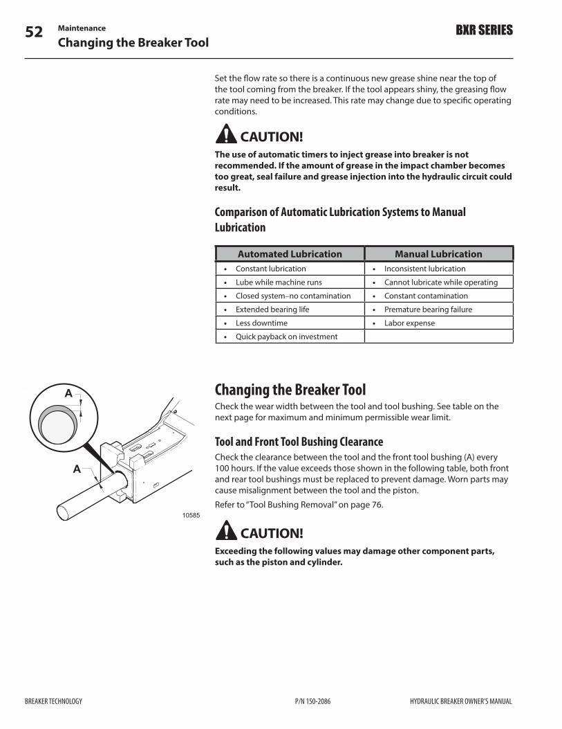
Maintenance52Changing the Breaker Tool
BREAKER TECHNOLOGY P/N 150-2086 HYDRAULIC BREAKER OWNER’S MANUAL
BXR SERIES
Set the "ow rate so there is a continuous new grease shine near the top of the tool coming from the breaker. If the tool appears shiny, the greasing "ow rate may need to be increased. This rate may change due to speci!c operating conditions.
CAUTION! The use of automatic timers to inject grease into breaker is not recommended. If the amount of grease in the impact chamber becomes too great, seal failure and grease injection into the hydraulic circuit could result.
Comparison of Automatic Lubrication Systems to Manual Lubrication
Automated Lubrication Manual Lubrication • Constant lubrication • Inconsistent lubrication
• Lube while machine runs • Cannot lubricate while operating
• Closed system–no contamination • Constant contamination
• Extended bearing life • Premature bearing failure
• Less downtime • Labor expense
• Quick payback on investment
Changing the Breaker ToolCheck the wear width between the tool and tool bushing. See table on the next page for maximum and minimum permissible wear limit.
Tool and Front Tool Bushing ClearanceCheck the clearance between the tool and the front tool bushing (A) every 100 hours. If the value exceeds those shown in the following table, both front and rear tool bushings must be replaced to prevent damage. Worn parts may cause misalignment between the tool and the piston. Refer to “Tool Bushing Removal” on page 76.
CAUTION! Exceeding the following values may damage other component parts, such as the piston and cylinder.
A
A
10585

Maintenance 53Changing the Breaker Tool
HYDRAULIC BREAKER OWNER’S MANUAL P/N 150-2086 BREAKER TECHNOLOGY
BXR SERIES
Permissible Nominal Minimum and Maximum Diameters for Wear Bushings and Breaker Tool
ModelBushing
Nominal Inside Dia. (new)in (mm)
BushingMaximum Inside Dia.
in (mm)
Working ToolMinimum Outside Dia.
in (mm)BXR50 5.5 (140) 5.669 (144) 5.354 (136)
BXR65 5.9 (150) 6.102 (155) 5.709 (145)
BXR85 6.3 (160) 6.496 (165) 6.102 (155)
BXR100 6.7 (170) 6.889 (175) 6.496 (165)
BXR120 7.1 (180) 7.283 (185) 6.890 (175)
BXR160 7.9 (200) 8.071 (205) 7.677 (195)
Tool Removal1) To remove the tool, drive out the retainer pin and stopper plug using the
drift supplied in the tool kit. 2) Use the drift to drive out the tool retainers. Inspect them for cracks or
deformities and wear on the edge that rests against the tool.
10586
1
2
1. Drift
2. Retainer Pin
3) Remove any burrs on the retainer pins and the tool with a grinder. Check for mushrooming on the top of tool.
4) If rotating the retainer pins, make sure the marked surface is towards the tool as shown.
10587
4
5
6
4. Tool Retainer
5. Drift
6. Tool

Maintenance54Changing the Breaker Tool
BREAKER TECHNOLOGY P/N 150-2086 HYDRAULIC BREAKER OWNER’S MANUAL
BXR SERIES
Tool InstallationTo install the tool, reverse the above procedure.1) First, grease the inside of the lower bushings. When the tool is inserted it
will take the grease with it.2) Cover the sides of the tool’s top section with grease and insert the tool
into the front head.
2
43
1
10588
1. Tool
2. Tool Retainer
3. Retainer Pin
4. Stopper Plug
3) Grease and insert the tool retainers, then grease and insert the retainer pins and silencer plugs. The silencer plugs should be "ush with the outside of front head.
10628
2
1
1. N2 Gas Regulator
2. N2 Gas Tank
Cushion Chamber Gas Pressure – CheckingIMPORTANT! Incorrect nitrogen gas pressure in the cushion chamber can damage the breaker and cause poor or erratic breaker behavior.
CAUTION! Stay clear of the tool when charging the breaker cushion chamber. Gas pressure may cause unexpected piston movement and force the tool to jump against the retainer pins.
CAUTION! The cushion chamber is charged with nitrogen (N2) – a non-explosive inert gas. Use only N2 when re!lling it. Charging it with any other gas could trigger an explosion and lead to serious or possibly fatal injuries.
IMPORTANT! Before charging the cushion chamber, make sure the tool is NOT pushed up inside the breaker. Lay the breaker down in a horizontal position.
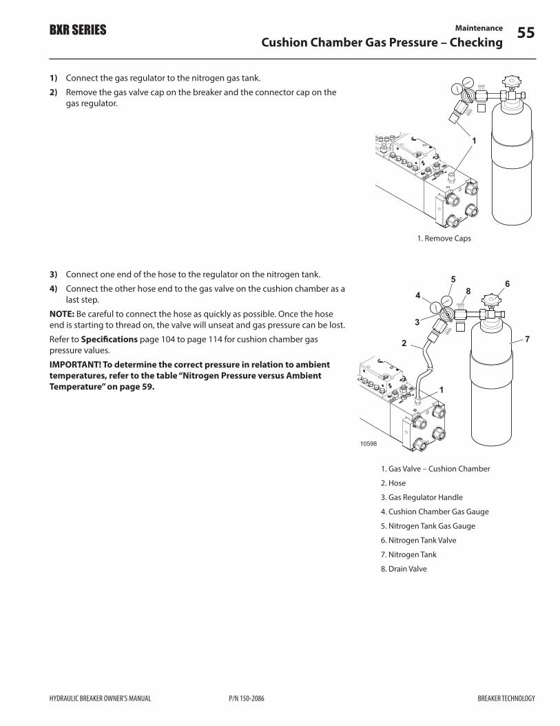
Maintenance 55Cushion Chamber Gas Pressure – Checking
HYDRAULIC BREAKER OWNER’S MANUAL P/N 150-2086 BREAKER TECHNOLOGY
BXR SERIES
1
105971. Remove Caps
1) Connect the gas regulator to the nitrogen gas tank.2) Remove the gas valve cap on the breaker and the connector cap on the
gas regulator.
3) Connect one end of the hose to the regulator on the nitrogen tank.4) Connect the other hose end to the gas valve on the cushion chamber as a
last step. NOTE: Be careful to connect the hose as quickly as possible. Once the hose end is starting to thread on, the valve will unseat and gas pressure can be lost. Refer to Speci!cations page 104 to page 114 for cushion chamber gas pressure values. IMPORTANT! To determine the correct pressure in relation to ambient temperatures, refer to the table “Nitrogen Pressure versus Ambient Temperature” on page 59.
10598
1
2
3
4
5 6
7
8
1. Gas Valve – Cushion Chamber
2. Hose
3. Gas Regulator Handle
4. Cushion Chamber Gas Gauge
5. Nitrogen Tank Gas Gauge
6. Nitrogen Tank Valve
7. Nitrogen Tank
8. Drain Valve

Maintenance56Cushion Chamber Gas Pressure – Adjusting
BREAKER TECHNOLOGY P/N 150-2086 HYDRAULIC BREAKER OWNER’S MANUAL
BXR SERIES
Cushion Chamber Gas Pressure – AdjustingModel Cushion Chamber
N2 PressureBXR50 145 psi (10 bar)
BXR65 145 psi (10 bar)
BXR85 131 psi (9 bar)
BXR100 145 psi (10 bar)
BXR120 159 psi (11 bar)
BXR160 159 psi (11 bar)
Increasing the Pressure1) Open the nitrogen tank by turning the tank valve (6) counter-clockwise
1/4 –1/2 turn. Tank pressure is indicated on the gauge (5).10625
5
6
2) Turn the gas regulator handle (3) clockwise to increase the gas pressure in the cushion chamber. The pressure is indicated on gauge (4). Increase pressure to the value shown in the table above.
NOTE: A small amount of pressure is lost when the hose is disconnected. To compensate, leave the pressure marginally over this value.3) Turn the gas regulator handle back counter-clockwise to stop increasing
the pressure.
10626
4
3
Decreasing the PressureIf the N2 pressure value in the cushion chamber is higher than the values shown in the table above, it must be reduced.1) Open the drain valve (8) by turning it counter-clockwise to reduce the
pressure. 2) Watch the gauge (4) and turn the valve clockwise to close it when the
target pressure indicated in the table above is met.
10627
4
8
Removing the Gauge and Hose1) Close the tank valve by turning it clockwise.2) Remove the hose end on the cushion chamber gas valve.NOTE: Be careful to disconnect the hose as quickly as possible. A certain amount of gas pressure can be lost before the valve seats itself.3) Disconnect the gauges from the tank.4) Perform a leak test on the cushion chamber gas valve by applying liquid
soap to the area. If bubbles appear, there is a gas leak. Check to make sure the valve has not malfunctioned.

Maintenance 57Accumulator Gas Pressure – Checking
HYDRAULIC BREAKER OWNER’S MANUAL P/N 150-2086 BREAKER TECHNOLOGY
BXR SERIES
Accumulator Gas Pressure – CheckingCheck accumulator gas pressure every 500 hours of operation.
CAUTION! The accumulator is charged with nitrogen (N2) – a non-explosive inert gas. Use only N2 when re!lling it. Charging it with any other gas could trigger an explosion and lead to serious or possibly fatal injuries.
IMPORTANT! Incorrect nitrogen gas pressure in the accumulator can damage the breaker and cause poor or erratic breaker behavior.
IMPORTANT! Hydraulic oil pressure MUST be fully vented inside the breaker before charging the accumulator. Residual pressure will result in an incorrect N2 charge pressure. 1) Ensure all hydraulic oil pressure inside the breaker body is fully vented.2) Connect the gas regulator to the nitrogen gas tank.3) Remove the gas valve cap on the accumulator and the connector cap on
the gas regulator. Connect one end of the hose to the regulator on the nitrogen tank.
4) Connect the other hose end to the gas valve on the accumulator as a last step.
NOTE: Be careful to connect the hose as quickly as possible. Once the hose end is starting to thread on, the valve will unseat and gas pressure can be lost.5) Accumulator gas pressure is indicated on tank gauge (5) with tank valve
closed. Ensure gas pressure is 754 psi (52 bar) at 68 ºF (20 ºC).
IMPORTANT! To determine the correct pressure in relation to ambient temperatures, refer to the table “Nitrogen Pressure versus Ambient Temperature” on page 59.
10599
1
2
3
4
5 6
7
8
1. Gas Valve – Accumulator
2. Hose
3. Gas Regulator Handle
4. Accumulator Gas Gauge
5. Nitrogen Tank Gas Gauge
6. Nitrogen Tank Valve
7. Nitrogen Tank
8. Drain Valve
10628
2
1
1. N2 Gas Regulator
2. N2 Gas Tank

Maintenance58Accumulator Gas Pressure – Adjusting
BREAKER TECHNOLOGY P/N 150-2086 HYDRAULIC BREAKER OWNER’S MANUAL
BXR SERIES
Accumulator Gas Pressure – AdjustingIncreasing the Pressure1) Open the nitrogen tank by turning the tank valve counter-clockwise 1/4
–1/2 turn. Accumulator pressure is indicated on the gauge (5).
10629
5 6
2) Increase the pressure to 754 psi (52 bar).NOTE: A small amount of pressure is lost when the hose is disconnected. To compensate, leave the pressure marginally over this value.3) Turn the nitrogen tank valve clockwise to stop increasing the pressure.
10630
5 6
Decreasing the PressureIf the nitrogen pressure value in the accumulator is higher than 754 psi (52 bar), it must be reduced.1) Open the drain valve (8) by turning it counter-clockwise to reduce the
pressure. 2) Watch the gauge (5) and turn the valve clockwise to close it when the
target pressure is met.
10631
58
Removing the Gauge and Hose1) Close the tank valve by turning it clockwise.2) Remove the hose end on the accumulator gas valve.NOTE: Be careful to disconnect the hose as quickly as possible. A certain amount of gas pressure can be lost before the valve seats itself.3) Disconnect the gauges from the tank.4) Perform a leak test on the accumulator gas valve by applying liquid soap
to the area. If bubbles appear, there is a gas leak. Check to make sure the valve has not malfunctioned.

Maintenance 59Nitrogen Charging Pressure versus Ambient Temperature
HYDRAULIC BREAKER OWNER’S MANUAL P/N 150-2086 BREAKER TECHNOLOGY
BXR SERIES
Nitrogen Charging Pressure versus Ambient TemperatureThe following table is a guide to cushion chamber and accumulator pressure values adjusted to ambient temperature di$erences.
• Allow the hydraulic breaker and the nitrogen bottle temperatures to normalize to room temperature in a shop environment.
• Adjust the accumulator and cushion chamber pressure as indicated in the tables below for the ambient temperature expected.
-50 -40 -22 -4 14 32 50 68 86 104 122 140 158 176
-50 -40 -22 -4 14 32 50 68 86 104 122 140 158 176
Temperature ºF
203
188
174
160
145
131
116
Accumulator Nitrogen Gas Pressure
Cushion Chamber Nitrogen Gas Pressure
8.0
9.0
10.0
11.0
12.0
13.0
14.0
-50 -40 -30 -20 -10 0 10 20 30 40 50 60 70 80
-50 -40 -30 -20 -10 0 10 20 30 40 50 60 70 80
Temperature ºF
Temperature ºC
Temperature ºC
35.0
40.0
45.0
50.0
55.0
60.0
65.0
bar
943
870
797
725
653
580
508
psi
bar psi
10589

Maintenance60Maintenance Schedule
BREAKER TECHNOLOGY P/N 150-2086 HYDRAULIC BREAKER OWNER’S MANUAL
BXR SERIES
BREAKER TECHNOLOGY P/N 150-2089 HYDRAULIC BREAKER OWNER’S MANUAL
BXR SERIES
Maintenance SchedulePre Shift
Verify correct operation of all machine functions.
Check for leaks, damaged hoses or clamps.
Check that all electrical components are in operational condition.
Grease the breaker tool, retainer pins and plugs with Chisel Paste. If equipped with auto lube system, ensure there is adequate grease in the reservoir.
Every 2 HoursVerify correct operation of all machine functions.
Grease breaker tool bushing. Pump grease in until it is visible around tool and retainer pins.
Check general condition of machine and surrounding work area.
Every 8 Hours – DailyCheck all screw connections for tightness (during !rst 50 hours of operation).
Check hydraulic oil level in carrier reservoir.
Check lubrication system.
Check all hardware and bolts for tightness.
Check all hydraulic lines, !ttings and clamps for leaks or damage.
Check breaker for damage, loose !ttings, or hydraulic leaks.
Every 50 Hours – WeeklyCheck torque on all fasteners every 50 hours of operation or after any major maintenance.
Check mounting pins for wear.
Check impact surface of tool for deformation.
Remove the breaker tool and retaining pins. Inspect the wearing surfaces. Remove any burrs before reinstalling. Refer to Service section if scu#ng marks are found on the tool.
Inspect upper isolator.
Use a hammer to ping (knock) the tie rods. The same tone will resonate if the tie rods are torqued equally. A loose tie rod will be immediately evident.

Maintenance 61Maintenance Schedule
HYDRAULIC BREAKER OWNER’S MANUAL P/N 150-2086 BREAKER TECHNOLOGY
BXR SERIES
HYDRAULIC BREAKER OWNER’S MANUAL P/N 150-2089 BREAKER TECHNOLOGY
BXR SERIES
Every 100 HoursRemove the breaker tool and inspect the wearing surface. Remove any burrs before reinstalling.
Inspect the tool retainer pins. Remove the pins, rotate 180 degrees and reinstall.After initial 100 hours of operation, change hydraulic pressure and return line !lter elements.
Check tool bushing clearance. See page 52.
Check that the pressure/return !lter indicators on the carrier hydraulic system are functioning correctly and not in by-pass.
Every 500 HoursTake a sample of the hydraulic oil. Review the results and determine if an increase in !lter change interval and/or oil change is required. File the results.
Check cushion chamber nitrogen gas pressure. Refer to “Cushion Chamber Gas Pressure – Checking” on page 54.Check accumulator nitrogen gas pressure. Refer to “Accumulator Gas Pressure – Adjusting” on page 58.
Perform all breaker checks above as required.
Check that the retainer pins, cross pins and stopper plugs are not damaged and are in place.Check that the upper isolator and tie rod nuts are in place and tight. Check for wear.
Every 1000 Hours or YearlyReplace the retainer pins.
Perform all breaker checks listed above as required.
Disassemble the breaker to replace all seals. Replace upper and lower breaker isolators inside the housing. Refer to page 87.
Measure the wear limit on the Front and Rear Bushings. Replace each bushing if the allowable tolerances are exceeded. Refer to page 52.
Check Hydraulic "ow to breaker and operating pressure. Adjust as necessary.

NOTES
62
BREAKER TECHNOLOGY P/N 150-2086 HYDRAULIC BREAKER OWNER’S MANUAL
BXR SERIES

Service 63Safety Warnings
HYDRAULIC BREAKER OWNER’S MANUAL P/N 150-2086 BREAKER TECHNOLOGY
BXR SERIES
ServiceSafety Warnings
WARNING! • Only trained mechanics should repair or disassemble the hydraulic
breaker. Be sure you understand a service procedure before beginning any work; if you are uncertain, contact your BTI representative.
• Avoid unauthorized machine modi!cations – never substitute alternate parts not intended for the application. This could create hazardous situations or machine failure. BTI Engineering must approve all machine modi!cations; they can a$ect product reliability and machine stability.
• Before performing any work on the machine, attach a DO NOT OPERATE or similar tag in the operator’s cab to alert others of service work being performed. Remove engine key and master key switch. Unexpected machine movement can cause serious injury.
• The accumulator and cushion chamber are charged with nitrogen (N2) – a non-explosive inert gas. Only use N2 when re!lling them. Charging with any other gas could trigger an explosion and lead to serious or possibly fatal injuries.
• Relieve all gas pressure in the accumulator and cushion chamber before beginning disassembly procedures to avoid the potential for accidents or injury. They remain under pressure even after the hydraulic system is depressurized. Refer to the maintenance section of this manual.
• Stay clear of the tool when charging the breaker cushion chamber. Gas pressure may cause unexpected piston movement and force the tool to jump against the tool retainer pins.
• Use only lifting devices with su#cient capacity to safely support the expected weight you are lifting.
• All lifting devices (straps, slings, chains, ratchet blocks, etc.) must comply with applicable local regulations and certi!cations. BTI cannot accept responsibility for the use of sub-standard equipment and work practices.
• When lifting or supporting the breaker or its parts, use equipment with a su#cient lifting capacity.
• Use the lifting eyes or lifting points that are located on certain breaker components.
• Do not work under a hanging or suspended load! • If a jack is used, the "oor or ground must be "at and of su#cient strength
to support the expected load. • Wear protective clothing – know and use the protective equipment that
is to be worn when servicing the hydraulic breaker. Hard hats, protective glasses, protective shoes, gloves, re"ector type vests, respirators and ear protection are types of equipment that may be required.
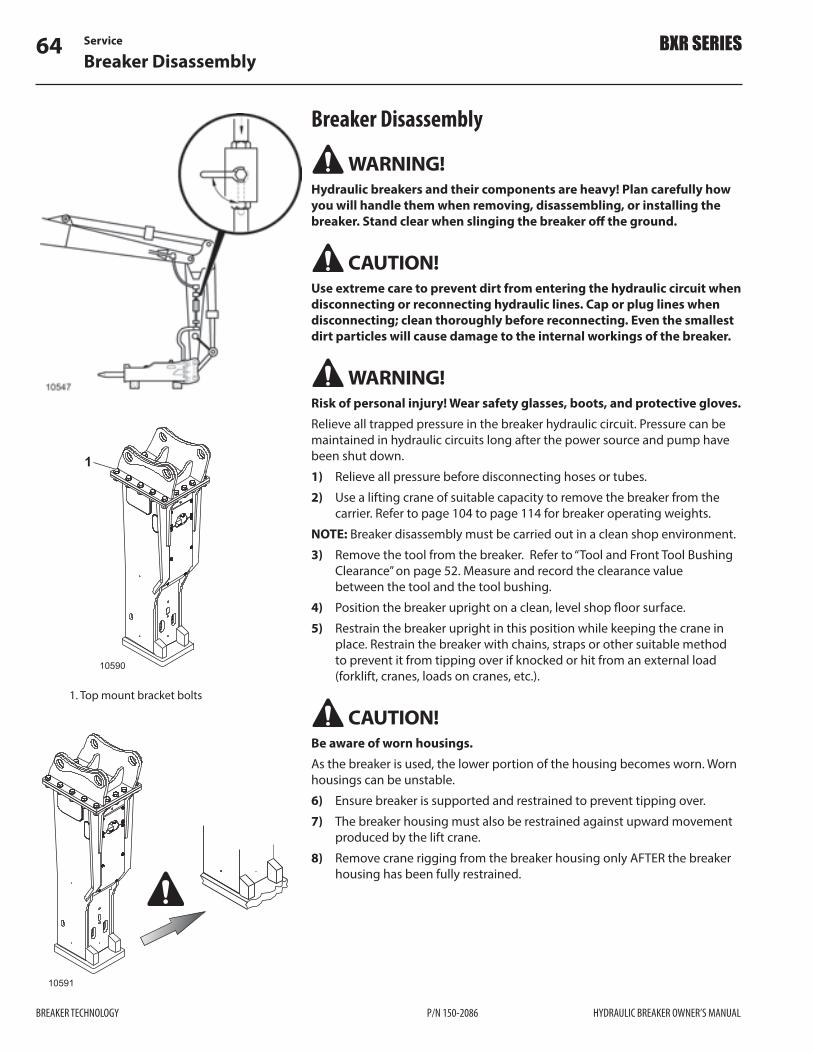
Service64Breaker Disassembly
BREAKER TECHNOLOGY P/N 150-2086 HYDRAULIC BREAKER OWNER’S MANUAL
BXR SERIES
Breaker Disassembly
WARNING! Hydraulic breakers and their components are heavy! Plan carefully how you will handle them when removing, disassembling, or installing the breaker. Stand clear when slinging the breaker o# the ground.
CAUTION! Use extreme care to prevent dirt from entering the hydraulic circuit when disconnecting or reconnecting hydraulic lines. Cap or plug lines when disconnecting; clean thoroughly before reconnecting. Even the smallest dirt particles will cause damage to the internal workings of the breaker.
WARNING! Risk of personal injury! Wear safety glasses, boots, and protective gloves.Relieve all trapped pressure in the breaker hydraulic circuit. Pressure can be maintained in hydraulic circuits long after the power source and pump have been shut down.1) Relieve all pressure before disconnecting hoses or tubes.2) Use a lifting crane of suitable capacity to remove the breaker from the
carrier. Refer to page 104 to page 114 for breaker operating weights.NOTE: Breaker disassembly must be carried out in a clean shop environment.3) Remove the tool from the breaker. Refer to “Tool and Front Tool Bushing
Clearance” on page 52. Measure and record the clearance value between the tool and the tool bushing.
4) Position the breaker upright on a clean, level shop "oor surface.5) Restrain the breaker upright in this position while keeping the crane in
place. Restrain the breaker with chains, straps or other suitable method to prevent it from tipping over if knocked or hit from an external load (forklift, cranes, loads on cranes, etc.).
CAUTION! Be aware of worn housings.As the breaker is used, the lower portion of the housing becomes worn. Worn housings can be unstable.6) Ensure breaker is supported and restrained to prevent tipping over.7) The breaker housing must also be restrained against upward movement
produced by the lift crane.8) Remove crane rigging from the breaker housing only AFTER the breaker
housing has been fully restrained.
10590
1
1. Top mount bracket bolts
10591

Service 65Breaker Disassembly
HYDRAULIC BREAKER OWNER’S MANUAL P/N 150-2086 BREAKER TECHNOLOGY
BXR SERIES
CAUTION! Upper and lower isolators inside the breaker housing are compressed to provide a preload on the breaker body to support it within the housing. Loosen bolts gradually and equally to remove pre-load and prevent injury.9) Loosen top mount bracket bolts gradually and equally to reduce spring
pre-load from isolators. Once all bolts have been loosened, the spring pre-load will be gone and it is safe to remove the bolts.
10) Remove top mount bracket bolts and bracket. Store in a safe place away from the work area.
The upper and lower isolators have a minimum thickness requirement for reuse. Refer to “Upper and lower Isolator Limits” on page 87. If they do not meet the minimum requirement, they must be replaced.11) Remove the upper isolator from the breaker and check for cracking, heat
damage, wear etc. If the isolator is in poor condition it must be replaced. NOTE: Upper and lower isolators must be replaced after 1000 hours of operation.
Removing Breaker Body from HousingNOTE: All lifting eyes required for breaker disassembly are found in the breaker tool kit.Besides the upper and lower isolators, the BXR breaker body has nylon support pads shimmed between it and the inside of the housing to keep it supported on all sides. They can be reused if in good condition.
IMPORTANT! Secure wear pads and shims to prevent damage before removing the breaker body from the housing.1) Secure the wear pads and shims on all four sides of the breaker housing.
A wood screw can be inserted through the access holes in the sides of the breaker housing. Ensure the screws DO NOT fully penetrate the wear pad.
10603
12
1. Shims
2. Nylon Support Pad
3. Access Holes
10602
3
33

Service66Breaker Disassembly
BREAKER TECHNOLOGY P/N 150-2086 HYDRAULIC BREAKER OWNER’S MANUAL
BXR SERIES
Bare Breaker Weight
Model Weightlb (kg)
Lifting Eye Size
BXR50 1,804 (818) M24
BXR65 2,163 (981) M24
BXR85 2,934 (1 331) M24
BXR100 3,474 (1 576) M30
BXR120 4,010 (1 819) M30
BXR160 5,540 (2 513) M30
CAUTION! Ensure breaker is restrained to prevent tipping over.2) Insert the appropriate lifting eyes into the rear head.3) Using an overhead crane, pull the breaker body straight up out of the
housing. 4) Carefully lower the bare breaker onto a smooth, clean, level surface.5) Mark the location of the wear pads and shims inside the housing and
then remove them. They could be placed back in the same location upon reassembly.
6) Clean inside of the housing. Inspect for weld cracks, damage etc. inside and outside of the housing. Repair as required.
7) Clean and inspect the front head area of the bare breaker. 8) Clean and inspect the shims and nylon support pads for wear, warping,
cracking etc. then set them aside for reuse. Wear pads must be replaced after 1000 hours of operation.
NOTE: The upper/lower isolators and wear pads are considered wear parts and are not covered under the breaker warranty.
10648
1
2
34
1. Upper Isolator
2. Lower Isolator (install with nylon side towards breaker)
3. Shim
4. Nylon Wear Pad

Service 67Breaker Body Disassembly
HYDRAULIC BREAKER OWNER’S MANUAL P/N 150-2086 BREAKER TECHNOLOGY
BXR SERIES
1
10593
1. Gas Valve
Breaker Body DisassemblyThe breaker body can be disassembled standing up or laying down. The following instructions describe the standing method.
WARNING! Release cushion chamber gas pressure before disassembly.
The cushion chamber in the rear head contains nitrogen gas under pressure. Do not remove the tie rod nuts or gas valve until this pressure is released.
WARNING! DO NOT use impact tools to disassemble or reassemble the breaker body. The tie rods and control valve bolts use heliserts (steel threaded inserts) that can be damaged by the use of impact tools.
Rear Head Removal1) Use the charging hose in tool kit to fully vent the N2 gas from the cushion
chamber.2) Insert lifting eyes into the rear head and stand the breaker on a safety
stand. 3) Remove the gas valve assembly to avoid accidental damage during
bushing replacement. Put it in a safe place for reuse later.4) Back o$ the tie rod nuts a couple of turns. This can be done using a
torque multiplier if the breaker is standing up. If the breaker is lying down, use the sledge-wrench method.
5) Using a hoist, jerk the assembly upwards slightly, which should loosen the rear head from the cylinder.
6) Place the rear head on a clean protective surface. 7) If the rear head is stuck, it may be necessary to tap the cylinder cover on
alternate sides with a soft-faced mallet. Remove the nuts and washers from the four tie rods.
8) Remove the rear head from the cylinder using lifting eyes. In some cases, the nuts may be seized onto the tie rod and may come out as a unit.
1
210594
1. Lifting Eye
2. Air Valve Assembly

Service68Breaker Disassembly
BREAKER TECHNOLOGY P/N 150-2086 HYDRAULIC BREAKER OWNER’S MANUAL
BXR SERIES
Accumulator Removal
WARNING! Release accumulator gas pressure before disassembly.
The accumulator contains nitrogen gas under pressure. Do not remove the bolts until this pressure is released.
WARNING! DO NOT use impact tools to remove the accumulator from the breaker body. The accumulator mounting bolts use heliserts (steel threaded inserts) that can be damaged by the use of impact tools.1) Take an initial reading of the nitrogen gas pressure in the accumulator. A
higher than normal reading may indicate a problem.
WARNING! A gas pressure reading in the accumulator higher than the last time it was charged indicates the diaphragm may have ruptured. Pressurized oil may exist in the accumulator. Proceed with caution.2) Bleed o$ the nitrogen gas with the charging kit hose. Fully vent the
accumulator. Con!rm with the gauge in the charging kit.3) Loosen the 4 bolts in a staggered pattern. Use multiple steps.4) Remove the accumulator from the breaker body.
Diaphragm Replacement
CAUTION! Nitrogen gas must be fully vented before disassembly.1) Con!rm the gas pressure has been fully vented with the charging kit hose
and gauge.2) Loosen the bolts holding the accumulator halves together in a staggered
pattern.3) Loosen the bolts o$ in 1/8 in (3 mm) increments; watch for movement.
Movement of the halves may mean residual pressure remains.4) Continue loosening the bolts in a staggered pattern.5) Remove the cover to replace the diaphragm.
1
2
12504
1. Helisert
2. Accumulator Mounting Bolts
12502
1
23
1. Retainer bolts and washers
2. Cover
3. Accumulator bleed nozzle

Service 69Breaker Disassembly
HYDRAULIC BREAKER OWNER’S MANUAL P/N 150-2086 BREAKER TECHNOLOGY
BXR SERIES
Control Valve Removal and Disassembly
CAUTION! Handle these components with care. Damaging them will cause breaker malfunction.
WARNING! DO NOT use impact tools to disassemble the control valve. Control valve bolts use heliserts (steel threaded inserts) that can be damaged by the use of impact tools.The control valve is responsible for directing oil within the breaker to move the piston within the cylinder. The external control valve is mounted to the side of the cylinder body.1) Remove the control valve bolts and washers, then lift the control valve
from the cylinder body. 2) Prepare the control valve for disassembly by washing it thoroughly and
clamping it in a vise.3) Remove control valve cap.4) If spool is not seized, it can be easily removed. A puller can assist in
removing a seized spool.
1
78
2
23
4
5
6
10606
1. Control Valve
2. Helisert
3. Lifting Eye
4. Valve Spool
5. Cover Bolts and Washers
6. Mounting Bolts and Washers
7. Stroke Adjuster Valve Assembly
8. Regeneration Valve Assembly
Accumulator Assembly1) Install the accumulator diaphragm into the accumulator base. Make sure
the groove is clean and free of any debris.2) Lubricate the cover bolt threads with MoS2 grease.3) Install the cover bolts and washers. Tighten in stages in a staggered
pattern.
ModelAccumulator Cover
Bolt Torqueft•lb (N•m)
BXR50 289 (391)
BXR65 398 (539)
BXR85 398 (539)
BXR100 398 (539)
BXR120 738 (1 000)
BXR160 738 (1 000)
If no further disassembly of the breaker is required, refer to Accumulator Installation on page 81.
12503
12
3
1. Accumulator Cover Bolts
2. Accumulator Cover
3. Accumulator Diaphragm

Service70Breaker Disassembly
BREAKER TECHNOLOGY P/N 150-2086 HYDRAULIC BREAKER OWNER’S MANUAL
BXR SERIES
5) Inspect the control valve spool for any signs of scoring, binding, and cavitation. Pay particular attention to the spool holes. Small scratches and marks may be removed with a !ne oilstone or !ne emery cloth and oil. Also check the control valve cap and valve body for marks or scratches, and remove them if they are not too severe. If the score marks are too deep or large, the complete control valve assembly must be replaced.
6) Examine the control valve ports for cavitation and erosion. Check all oil passage holes in the control valve and be sure they are not plugged. Clean them with a !ne wire if necessary to remove any dirt particles.
7) While the cover seals are still in place, inspect for nicks, score marks or damage. Replace if necessary.
8) At this time, the stroke adjuster and regeneration valves can be removed, cleaned and inspected as required.
Control Valve Inspection • If the valve spool surface is scu$ed, remove it with 800-1200 grit emery
cloth. If the area is extremely damaged, replace the valve.
• If the valve body has "aws in area D, smooth the surface with 800–1200 grit emery cloth. Do not use a bu#ng grinder on this area.
• If area D2 is scu$ed so badly that it is hard to de burr, the use of a bu#ng grinder is permitted, then !nish the face with emery cloth.
• In case of scu#ng on the inner diameter G, !nish by bu#ng with a "ap wheel.
• Clean all parts of the control valve in clean solvent and dry them with compressed air.
10607Control Valve Spool
D2
D
10608
Control Valve Body
G
10609Control Valve Cap

Service 71Breaker Disassembly
HYDRAULIC BREAKER OWNER’S MANUAL P/N 150-2086 BREAKER TECHNOLOGY
BXR SERIES
Control Valve Assembly
WARNING! DO NOT use impact tools to reassemble the control valve. Control valve bolts use heliserts (steel threaded inserts) that can be damaged by the use of impact tools.1) Lightly oil the control valve spool with clean hydraulic oil.2) Slide the spool into the valve body–smallest diameter !rst.3) Lubricate the grooves in the valve cap and install the o-ring and backup
ring.4) Place the valve body in a vise. 5) Lubricate bolts with MoS2 grease or Never Seize.6) Install the valve cap, bolts and washers.
1
2
10610
1. Valve Spool
2. O-ring and Backup Ring
1
23
4
5 6
10611
7) Torque the fasteners in a diagonal pattern. Use stages of 60%, 80%, and 100%.
Valve Cap Bolt Torque
Model Torque ValueBXR50 450 ft•lb (610 N•m)
BXR65 575 ft•lb (780 N•m)
BXR85 575 ft•lb (780 N•m)
BXR100 1,160 ft•lb (1 572 N•m)
BXR120 1,160 ft•lb (1 572 N•m)
BXR160 1,160 ft•lb (1 572 N•m)
To reinstall the control valve when no further disassembly is required, refer to “Control Valve Installation” on page 81.

Service72Breaker Disassembly
BREAKER TECHNOLOGY P/N 150-2086 HYDRAULIC BREAKER OWNER’S MANUAL
BXR SERIES
Piston Removal
CAUTION! Handle these components with care. Damaging them will cause breaker malfunction.1) Install a lifting eye into the top of the piston.2) Lift the piston straight up and out of the cylinder.NOTE: Avoid scratching the piston’s polished surface. Tapping the cylinder with a soft-faced mallet may ease the removal of the piston. The seal bushing will come out with the piston.3) Place the piston and seal bushing on a clean protective surface.4) The piston should be carefully cleaned and inspected for corrosion,
cavitation, pitting, and scoring.5) Check the grooves in the piston for metal that has been pulled-in due
to galling. If this has occurred, clean the grooves. Small marks can be removed with an oilstone or !ne emery cloth and oil. Check the corresponding mating part as well and treat in the same manner.
6) Look for pitting and deformation of the impact face. This indicates that the tool has been operated with too much wear on the tool bushings.
7) If the face is dished, carefully measure the amount of deformation. Compare to the table below.
Maximum Allowable Piston Deformation
Breaker Model
Allowable Deformation on Face
'A'
Maximum Deformation Diameter
'B'BXR50 1/8 in (3 mm) 4.33 +1/16 in (110 +1,6 mm)
BXR65 1/8 in (3 mm) 4.72 +1/16 in (120 +1,6 mm)
BXR80 1/8 in (3 mm) 5.04 +1/16 in (125 +1,6 mm)
BXR100 1/8 in (3 mm) 5.39 +1/16 in (137 +1,6 mm)
BXR120 1/8 in (3 mm) 5.59 +1/16 in (142 +1,6 mm)
BXR160 1/8 in (3 mm) 5.98 +1/16 in (152 +1,6 mm)
8) Thoroughly clean and dry the piston to protect it from dirt, then set it aside.
9) If the piston is not going to be installed immediately, coat it with oil and store it protected in a clean, dry place.
1. Normal Impact Face
2. Impact Face with Deformation
10612
1
2
3
1. Lifting Eye
2. Seal Bushing
3. Piston

Service 73Breaker Disassembly
HYDRAULIC BREAKER OWNER’S MANUAL P/N 150-2086 BREAKER TECHNOLOGY
BXR SERIES
Cylinder Removal
CAUTION! Handle this component with care. Damage will cause breaker malfunction.1) Install 2 lifting eyes into the top of the cylinder.2) Lift the cylinder straight up o$ the tie rods. 3) Loosen and remove the tie rods. It may be necessary to secure the front
head to prevent it from rotating.4) Loosen the tie rods by rotating them counter-clockwise. Use an
adjustable wrench and a soft faced mallet or a sledge wrench on the tie rod "ats to loosen them.
The cylinder should slip out of the front head. If not, tap the front head with a soft-faced mallet until the cylinder and front head come apart.
10614
If the piston face is scu$ed, !nish it with a bu#ng grinder, then 800–1200 grit emery cloth. Refer to “Clearances Between Cylinder and Piston” on page 75.
IMPORTANT: When using a bu$ng grinder, apply the "ap wheel around the circumference of the part only. If applied along the axis, roundness of the part will be a#ected. Wash the parts after !nishing them.
10615
Cylinder Inspection • Thoroughly clean the cylinder bore, and remove the dust seal, oil seal,
and slide ring. Check the seals for signs of extension and excessive wear both before and after removal.
• Thoroughly inspect inside walls of the cylinder for corrosion, cavitation, or scoring. Check grooves above seal area for small pieces of metal, due to galling. If these are not cleaned out they will chip o$ and go between the piston and cylinder, and galling will occur again.
• Check for any damage to the heliserts that secure the control valve. Repair or replace as necessary to ensure the valve can be installed properly.
• Inspect the main inlet and outlet adapter threads for damage. Always replace the seals if they are removed.

Service74Breaker Disassembly
BREAKER TECHNOLOGY P/N 150-2086 HYDRAULIC BREAKER OWNER’S MANUAL
BXR SERIES
10616
CAUTION! Do not install the hydraulic adapters in the wrong port. The pressure adapter has a smaller through hole than the tank adapter.The cylinder is marked “IN” beside the pressure adapter and “OUT” beside the tank adapter.
Cylinder Clean-upAny slight galling and other irregularities on the cylinder wall must be removed before reassembly. Use a cylinder hone to ensure the cylindricity of the bore is maintained. After using a hone, deburr the edges of all the lands.The preferred method to remove irregularities is to use a blade (!xed type) hone. A second method is to use a "exible hone. The amount of deburring required will be reduced with the "exible hone.A die grinder should only be used for deburring edges and severe local points of galling.If damage is too great, call your BTI representative.
• Check the slide areas A, B and C for "aws. If there are scu#ng "aws, !nish the surface smooth with a cylinder hone.
• If there are "aws in area D, use 800–1200 grit emery cloth. Never use a bu#ng grinder in this area.
• Area E can be !nished by bu#ng with a grinder.
Refer to “Clearances Between Cylinder and Piston”.Wash the parts after !nishing them.

Service 75Breaker Disassembly
HYDRAULIC BREAKER OWNER’S MANUAL P/N 150-2086 BREAKER TECHNOLOGY
BXR SERIES
Ø6.496 (165) Ø6.890 (175)
(176)Ø6.929 (186,5)Ø7.343
(186)Ø7.323
B
C
A Nominal Dimension:
Maximum Clearance:
Nominal Dimension:
Maximum Clearance:
Nominal Dimension:
Maximum Clearance:
D Nominal Dimension:
Maximum Clearance:
Ø6.929 (176)
.0067 (0,17) .0067 (0,17) .0067 (0,17) .0067 (0,17)
.0067 (0,17) .0067 (0,17) .0067 (0,17) .0067 (0,17)
.0067 (0,17) .0067 (0,17) .0067 (0,17) .0067 (0,17)
in (mm)
Ø5.902 (150)
Ø6.299 (160)
Ø5.705 (145)
Ø6.102 (155)
.0067 (0,17) .0067 (0,17)
.0067 (0,17)
.0067 (0,17) .0067 (0,17)
.0067 (0,17)
Ø6.102 (155)
.0067 (0,17)
Ø5.591 (142)
.0067 (0,17)
Ø5.746 (146)
.0067 (0,17)
Ø6.378 (162)
.0067 (0,17)
Ø6.732 (171)
.0067 (0,17)
Ø6.890 (175)
.0067 (0,17)
Ø7.283 (185)
Ø6.299 (160)
Ø7.480 (190)
Ø8.150 (207)
Ø7.087 (180)
Ø7.683 (194)
Ø7.683 (194) Ø8.150 (207)
Breaker Model BXR50 BXR65 BXR85 BXR100 BXR120 BXR160
A B C D
10618
Maximum Clearances Between Cylinder and Piston
10617
IMPORTANT: When using a bu$ng grinder, apply "ap around the inside diameter of the part only. If applied along the axis, roundness will be a#ected.

Service76Breaker Disassembly
BREAKER TECHNOLOGY P/N 150-2086 HYDRAULIC BREAKER OWNER’S MANUAL
BXR SERIES
Tool Bushing Removal
CAUTION! The tool bushings are a shrink-!t in the front head and the following procedure must be followed for removal. Do not gouge the bushings out with an oxyacetylene torch or other method.NOTE: The front tool bushing can be removed without disassembling the breaker.NOTE: The breaker must be disassembled to change the rear tool bushing. If it is not disassembled, refer to “Breaker Disassembly” on page 64. Disassembly is necessary to protect the internal components of the breaker.NOTE: If new bushings are to be installed immediately after removing the old ones, place them in dry ice before starting the removal procedure.Dry ice can take up to four hours to achieve the desired results. The bushings will be fully chilled then, and the front head will still be hot enough from the welding to receive them. If using liquid nitrogen to shrink the bushings, it can take as little as !fteen minutes to properly chill them.1) Remove the grease !tting to avoid accidental damage during bushing
replacement. Put it in a safe place for reuse later.
1. Grease Fitting
Seal Bushing InspectionClean and inspect the cylinder seal bushing.The seal bushing carries several specially designed seals. Pay attention to the condition and orientation of the old seals as they are removed. This may help to identify any operating problems that the breaker had before it was dismantled.If burrs are found on the seal bushing, use a bu#ng grindstone to remove them.IMPORTANT: When using a bu$ng grinder, apply the "ap wheel around the inside diameter of the part only. If applied along the axis, roundness will be a#ected.
CAUTION! Handle this component with care. Damage will cause breaker malfunction.All parts should be thoroughly washed in clean solvent and dried with compressed air. Once the seal bushing is clean and dry, protect it from dirt and set it aside.
10338

Service 77Breaker Body Assembly
HYDRAULIC BREAKER OWNER’S MANUAL P/N 150-2086 BREAKER TECHNOLOGY
BXR SERIES
Breaker Body AssemblyNOTE: Torque Speci!cations are listed for BXR breakers starting on page 116.
Tool Bushing InstallationThe rear and front bushings are installed from the tool side of the front head. Clean the inside of the front head thoroughly. Use a wire rotary brush to clean and smooth the surfaces in the areas where the bushings seat.
IMPORTANT! The bushings are a shrink !t in the front head. Use extreme care when installing the tool bushings. To obtain this !t, the front head must be heated so that it will expand, and the bushings placed in liquid nitrogen or dry ice, so they will contract. As the pieces return to room temperature, they become tightly !tted together.
IMPORTANT! The rear tool bushing must go in !rst.1) Mark the front head and bushings for correct alignment during assembly. 2) Place the tool bushings in dry ice for 4 hours or liquid nitrogen for 30
minutes.
1
2
3
4
10336
1. Mark Front Head and Bushing
2. Front Tool Bushing
3. Rear Tool Bushing
4. Front Head
1
2
34
546
10335
1. Stopper Plug
2. Retainer Pin
3. Rear Tool Bushing
4. Tool Bushing Alignment Slot
5. Drift
6. Front Tool Bushing
The tool bushings are held in position by four retainer pins. 2) Remove these pins by driving them out with a drift, from the side
opposite the stopper plugs.3) Lay the front head on it’s side.The recommended method of shrinking the bushings is to lay crescent-shaped beads of weld inside the tool bushings. Use an arc welder and a very hot weld.4) Start with the front tool bushing. 5) Lay beads of weld to completely cover the inside of the bushing.
(Depending on the breaker bushing size, this could take from one-half to three hours.)
6) Allow the bushing to cool for about one-half hour so the weld will contract and shrink the bushing. This time will be less for smaller breakers.
IMPORTANT! Do not quench the bushing to cool it faster.7) Knock the bushing out with a bar from the top end of the front head.
Repeat the procedure for the upper bushing.

Service78Breaker Body Assembly
BREAKER TECHNOLOGY P/N 150-2086 HYDRAULIC BREAKER OWNER’S MANUAL
BXR SERIES
Tie Rod Installation
WARNING! DO NOT use impact tools to reinstall the tie rods. The tie rods use heliserts (steel threaded inserts) that can be damaged by the use of impact tools.Inspect the tie rod threads. If they are damaged beyond repair, the tie rod must be replaced.1) Lubricate the tie rods and threads thoroughly using MoS2 (moly-based)
grease or Never Seize. 2) Install the tie rods and tighten until they bottom out in the front head.3) The tie rods should turn in smoothly and easily until they seat themselves.
If they do not bottom out or there is excessive resistance, the threads on the tie rods or the helisert may be damaged. Remove damaged heliserts and restore the front head threads with conventional thread dies and taps.
4) Insert new heliserts with an insertion tool.NOTE: As a reference, tie rod torque is listed in torque Speci!cations starting on page 116.
10337
1
2
3
1. Helisert
2. Tie Rod
3. Apply grease
CAUTION! Wear appropriate gloves when handling these parts. Bare skin will freeze on contact.
CAUTION! If the bushings are not installed properly before this point is reached, they must be taken out and replaced with new ones. With liquid nitrogen, there is about one minute to align the retainers.3) If the front head has cooled, it must be heated to 300 °F (150 °C). This will
expand the housing a small amount. 4) Apply a coat of Never-Seize to the retaining pins and have them ready
nearby.5) Line up the slots in the rear tool bushing with the retainer holes and
insert it into the front head.
IMPORTANT! Care must be taken to ensure that the grooves in the tool bushings line up with the retainer pin holes in the front head.When fully inserted, the rear tool bushing will seat against the step in the bore of the front head. 6) Fully insert the retaining pins into the retaining pin holes. Do not install
the stopper plugs until the front head has cooled to room temperature.7) Repeat the procedure for the front bushing.8) Install the previously removed grease !tting in the front head.

Service 79Breaker Body Assembly
HYDRAULIC BREAKER OWNER’S MANUAL P/N 150-2086 BREAKER TECHNOLOGY
BXR SERIES
Cylinder Installation 1) Check the cylinder for burrs. 2) Liberally oil the inside surface of the cylinder and the new seals, then
install the seals and rings into the grooves at the lower end of the cylinder.
Pay close attention to the correct placement and orientation of the seals. Improper seal installation will cause premature leakage and premature wear. 3) Lower the cylinder carefully onto the tie rods. The control valve mounting
holes on the cylinder must face the same direction as the grease !tting on the front head.
12505
2
1
5
3
4
1. Lower Cylinder
2. Bu$er Seal
3. U-packing
4. Dust Seal
12506
9
9
6
9
7
8
10
6. Seal Bushing
7. Quad Ring
8. Step Seal
9. O-ring
10. Bu$er Seal
Seal Bushing – Re-sealingEnsure the bushing is clean and there are no burrs.1) Oil the seal bushing and seals. 2) Install the seals and o-rings in the correct positions and orientations.
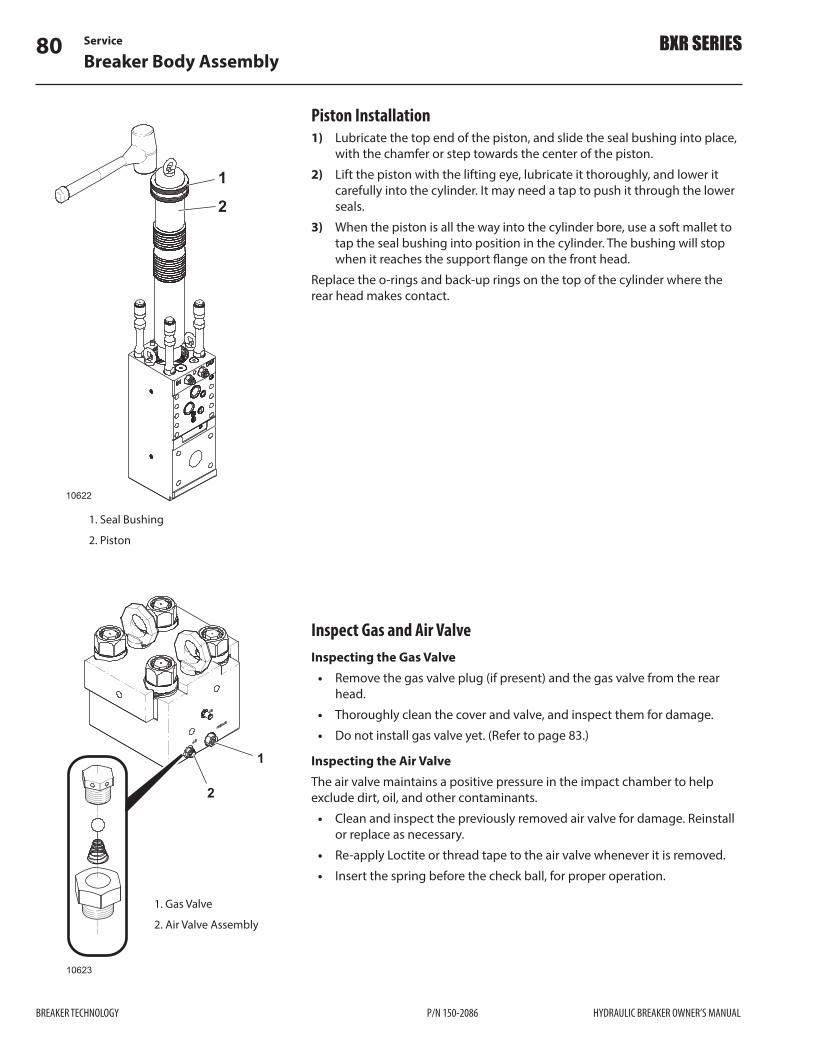
Service80Breaker Body Assembly
BREAKER TECHNOLOGY P/N 150-2086 HYDRAULIC BREAKER OWNER’S MANUAL
BXR SERIES
Inspect Gas and Air ValveInspecting the Gas Valve
• Remove the gas valve plug (if present) and the gas valve from the rear head.
• Thoroughly clean the cover and valve, and inspect them for damage. • Do not install gas valve yet. (Refer to page 83.)
Inspecting the Air ValveThe air valve maintains a positive pressure in the impact chamber to help exclude dirt, oil, and other contaminants.
• Clean and inspect the previously removed air valve for damage. Reinstall or replace as necessary.
• Re-apply Loctite or thread tape to the air valve whenever it is removed. • Insert the spring before the check ball, for proper operation.
10623
1
2
1. Gas Valve
2. Air Valve Assembly
Piston Installation1) Lubricate the top end of the piston, and slide the seal bushing into place,
with the chamfer or step towards the center of the piston.2) Lift the piston with the lifting eye, lubricate it thoroughly, and lower it
carefully into the cylinder. It may need a tap to push it through the lower seals.
3) When the piston is all the way into the cylinder bore, use a soft mallet to tap the seal bushing into position in the cylinder. The bushing will stop when it reaches the support "ange on the front head.
Replace the o-rings and back-up rings on the top of the cylinder where the rear head makes contact.
10622
1
2
1. Seal Bushing
2. Piston

Service 81Breaker Body Assembly
HYDRAULIC BREAKER OWNER’S MANUAL P/N 150-2086 BREAKER TECHNOLOGY
BXR SERIES
Control Valve Installation
WARNING! DO NOT use impact tools to install the control valve. Control valve bolts use heliserts (steel threaded inserts) that can be damaged by the use of impact tools.NOTE: Nordlock washers cannot be reused. They must be replaced.1) Before attaching the control valve to the cylinder, make sure all the seals
are in place. Refer to the Parts Section for correct orientation.Use only hand tools to tighten the bolts as they thread into special hardened heliserts that can be damaged by impact tools.2) Use MoS2 grease to lubricate bolt threads.3) Tightened in a staggered pattern from one side to other to prevent
binding. Tighten in stages of 60%, 80%, 100% of torque value.
Model Valve Case Bolt Torque
BXR50 450 ft•lb (610 N•m)
BXR65 575 ft•lb (780 N•m)
BXR85 575 ft•lb (780 N•m)
BXR100 1,160 ft•lb (1 572 N•m)
BXR120 1,160 ft•lb (1 572 N•m)
BXR160 1,301 ft•lb (1 762 N•m)
Accumulator Installation WARNING! DO NOT use impact tools to install the accumulator. Accumulator bolts use heliserts (steel threaded inserts) that can be damaged by the use of impact tools.Use only hand tools to tighten the bolts as they thread into special hardened heliserts that can be damaged by impact tools.1) If the di$user was disassembled, reassemble it.
Di#user Nut Torques* A BBXR50 434 ft•lb (588 N•m) 470 ft•lb (637 N•m)
BXR65 434 ft•lb (588 N•m) 470 ft•lb (637 N•m)
BXR85 434 ft•lb (588 N•m) 470 ft•lb (637 N•m)
BXR100 434 ft•lb (588 N•m) 470 ft•lb (637 N•m)
BXR120 810 ft•lb (1 098 N•m) 846 ft•lb (1 147 N•m)
BXR160 810 ft•lb (1 098 N•m) 846 ft•lb (1 147 N•m)
* Lubricated – cleaned, dry threads lubricated with standard medium viscosity machine oil.
10624
12507
2
1
3
6 5
4 A
B
1. Accumulator Cover Bolts
2. O-ring
3. Back-up Ring
4. Ori!ce Assembly
5. PLUG
6. Di$user Nuts

Service82Breaker Body Assembly
BREAKER TECHNOLOGY P/N 150-2086 HYDRAULIC BREAKER OWNER’S MANUAL
BXR SERIES
2) Lubricate the accumulator mounting bolt threads with MoS2 grease or Never Seize.
3) Install the mounting bolts and washers. Tighten in a staggered pattern.
Model Accumulator Mounting Bolt Torque
BXR50 738 ft•lb (1 000 N•m)
BXR65 1,364 ft•lb (1 848 N•m)
BXR85 1,364 ft•lb (1 848 N•m)
BXR100 1,364 ft•lb (1 848 N•m)
BXR120 1,374 ft•lb (1 863 N•m)
BXR160 1,374 ft•lb (1 863 N•m)
12508
1
2
1. Helisert
2. Accumulator Mounting Bolt
Charging the AccumulatorBefore the breaker is put into service, the accumulator must be recharged with N2 gas.Before proceeding, refer to “Safety Rules” on page 27.Refer to “Accumulator Gas Pressure - Adjusting” on page 58 for proper procedure.
10599
1
2
3
4
5 6
7
8
1. Gas Valve – Accumulator
2. Hose
3. Gas Regulator Handle
4. Accumulator Gas Gauge
5. Nitrogen Tank Gas Gauge
6. Nitrogen Tank Valve
7. Nitrogen Tank
8. Drain Valve

Service 83Breaker Body Assembly
HYDRAULIC BREAKER OWNER’S MANUAL P/N 150-2086 BREAKER TECHNOLOGY
BXR SERIES
Installing the Rear HeadThe cushion chamber in the rear head needs a small amount of oil to function properly. Just before installing the rear head, make a circular dam of grease on the top of the piston, just high enough to contain the required amount of oil (see table below).1) Lower the rear head over the tie rods. The gas valve must face the same
direction as the control valve on the cylinder.2) Install the tie rod washers. 3) Lubricate the tie rod nuts with MoS2 grease, and tighten them in a
crossing pattern to draw the breaker components together evenly. 4) Finish tightening the nuts to the correct torque in four stages –40%, 60%,
80% and 100% using the same crossing pattern.
Tie rod Nut Torque
Model Torque ValueBXR50 1,808 ft•lb (2 452 N•m)
BXR65 1,808 ft•lb (2 452 N•m)
BXR85 2,604 ft•lb (3 528 N•m)
BXR100 3,617 ft•lb (4 900 N•m)
BXR120 3,617 ft•lb (4 900 N•m)
BXR160 4,702 ft•lb (6 371 N•m)
5) Pour in the required amount of oil into the cushion chamber through the gas valve port. Use a medium viscosity hydraulic oil.
Cushion Chamber Oil Volume
Model oz ml
BXR50 10 300
BXR65 12 350
BXR85 13.5 400
BXR100 15.2 450
BXR120 20.2 600
BXR160 27 800
6) Cover the gas valve threads with a good quality thread sealer and install the gas valve. Torque to 26 ft•lb (35 N•m).
1 4
3 2
10632
12
3
1. Tie Rod Nut
2. Nordlock Washer
3. Centralizer Washer

Service84Breaker Assembly
BREAKER TECHNOLOGY P/N 150-2086 HYDRAULIC BREAKER OWNER’S MANUAL
BXR SERIES
10598
1
2
3
4
5 6
7
8
1. Gas Valve – Cushion Chamber
2. Hose
3. Gas Regulator Handle
4. Cushion Chamber Gas Gauge
5. Nitrogen Tank Gas Gauge
6. Nitrogen Tank Valve
7. Nitrogen Tank
8. Drain Valve
Charging the Cushion ChamberBefore the breaker is put into service, the cushion chamber must be recharged with N2 (nitrogen) gas.Before proceeding, refer to “Safety Warnings” on page 63.Refer to “Cushion Chamber Gas Pressure – Adjusting” on page 56 for proper procedure.
Breaker Assembly(Installing body into boxed frame)
WARNING! Hydraulic breakers and their components are heavy! Plan carefully how you will handle them when removing, disassembling, or installing the breaker. Stand clear when slinging the breaker o# the ground.Besides the upper and lower isolators, the lower portion of the BXR breaker body is shimmed in two places on all sides for a close !t inside the housing. Nylon support pads keep the body supported and help to dampen vibration. Shims are used to attain the required !t inside the housing.Before installing the breaker body into the housing, the correct number of shims must be determined and support pads !xed in place inside the housing. Verify the quantity and condition of the support pads and shims. Eight support pads are required—two per side of the breaker body. Shims and support pads can be reused if in good condition.
10603
12
1. Shims
2. Nylon Support Pad
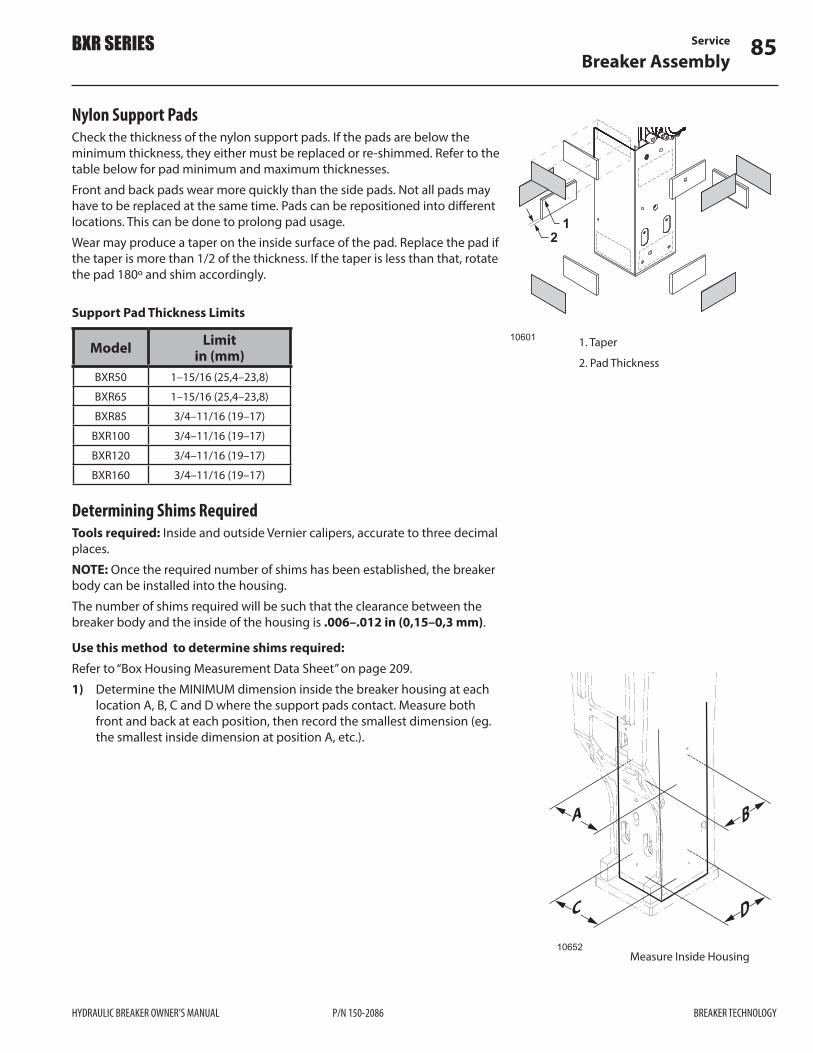
Service 85Breaker Assembly
HYDRAULIC BREAKER OWNER’S MANUAL P/N 150-2086 BREAKER TECHNOLOGY
BXR SERIES
Nylon Support PadsCheck the thickness of the nylon support pads. If the pads are below the minimum thickness, they either must be replaced or re-shimmed. Refer to the table below for pad minimum and maximum thicknesses.Front and back pads wear more quickly than the side pads. Not all pads may have to be replaced at the same time. Pads can be repositioned into di$erent locations. This can be done to prolong pad usage.Wear may produce a taper on the inside surface of the pad. Replace the pad if the taper is more than 1/2 of the thickness. If the taper is less than that, rotate the pad 180º and shim accordingly.
Support Pad Thickness Limits
Model Limitin (mm)
BXR50 1–15/16 (25,4–23,8)
BXR65 1–15/16 (25,4–23,8)
BXR85 3/4–11/16 (19–17)
BXR100 3/4–11/16 (19–17)
BXR120 3/4–11/16 (19–17)
BXR160 3/4–11/16 (19–17)
Determining Shims RequiredTools required: Inside and outside Vernier calipers, accurate to three decimal places. NOTE: Once the required number of shims has been established, the breaker body can be installed into the housing.The number of shims required will be such that the clearance between the breaker body and the inside of the housing is .006–.012 in (0,15–0,3 mm).
Use this method to determine shims required:Refer to “Box Housing Measurement Data Sheet” on page 209.1) Determine the MINIMUM dimension inside the breaker housing at each
location A, B, C and D where the support pads contact. Measure both front and back at each position, then record the smallest dimension (eg. the smallest inside dimension at position A, etc.).
10601
12
1. Taper
2. Pad Thickness
Measure Inside Housing
C
A
10652
D
B

Service86Breaker Assembly
BREAKER TECHNOLOGY P/N 150-2086 HYDRAULIC BREAKER OWNER’S MANUAL
BXR SERIES
2) Measure breaker body where the support pads will contact in both directions. Record measurements from positions A, B, C, and D.
3) Measure the combined thickness of the two support pads available for use in each area A, B, C, and D. Record this information.
4) Add measurements from Step 2, Step 3 and a Clearance Dimension of .006 in (0,15 mm) together, for each position A, B, C, and D. Record this number.
5) Subtract the result of Step 4 from Step 1 for each position A, B, C, and D. This result is the total shim thickness required. The nominal thickness of one shim is 3/64 in [0.047 in ] (0,3 mm).Try to balance the shims in an equal number for both sides.
10653
10654
C D
AB
Measure Breaker Body
10657
10656
Alternate Method1) Use pieces of lead solder .025 in (0,6 mm) thick, 1.5 in (38 mm) long
twisted into the shape shown.2) Tape four pieces to one side of each support pad, about 2 in (50 mm)
in from the corners. This will be the measurement point after they have been compressed.

Service 87Breaker Assembly
HYDRAULIC BREAKER OWNER’S MANUAL P/N 150-2086 BREAKER TECHNOLOGY
BXR SERIES
3) Install the wear pads with the solder pieces between the housing and the support pad.
4) Secure the support pads in place using wood screws through the holes provided in the housing.
5) Perform this operation for 2 sets of pads at a time, eg. front to back.6) Make sure the lower isolator is in place, then carefully lower the breaker
into the housing.7) Remove the breaker, then measure the compressed thickness of the
solder pieces at each position A, C, or B, D. 8) Record this information on the data sheet.9) Repeat the procedure for the other direction and record the data.The average thickness of these pieces in pockets A, B, C and D is total shim thickness required for that pocket.
C
A
10652
D
B
10648
1
2
34
1. Upper Isolator
2. Lower Isolator (install with nylon side towards breaker)
3. Shim
4. Nylon Support Pad
Upper and lower Isolator LimitsThe BXR breaker uses upper and lower isolators to support the breaker body within the housing.
IMPORTANT! After the top mount bracket is installed, the upper and lower isolators must compress to form a spring pre-load on the breaker body within the housing. If the breaker body has been disassembled to be rebuilt, replace the isolators. As a reference, see the table to follow. If the isolators are in good condition, and fall within the thickness limits shown, they can be reused Isolators must protrude above the breaker housing (dimension A) when assembled.
CAUTION! Ensure there is a positive preload on the isolators at !nal assembly.If the upper and lower isolator’s thickness has been permanently deformed and falls outside of the limits shown below, they must be replaced.

Service88Breaker Assembly
BREAKER TECHNOLOGY P/N 150-2086 HYDRAULIC BREAKER OWNER’S MANUAL
BXR SERIES
Model Isolator Limitin (mm)
BXR50Upper 4.94–4.81 (125–122)
Lower 2.37–2.25 (60–57)
BXR65Upper 4.94–4.81 (125–122)
Lower 2.37–2.25 (60–57)
BXR85Upper 4.94–4.81 (125–122)
Lower 2.37–2.25 (60–57)
BXR100Upper 4.94–4.81 (125–122)
Lower 3.12–3.0 (80–77)
BXR120Upper 4.94–4.81 (125–122)
Lower 2.56–2.31 (64,5–59)
BXR160Upper 4.94–4.81 (125–122)
Lower 2.56–2.31 (64,5–59)
1
A
A
BXR50 – BXR100 3/16 ±1/16 in (5 ±1,6 mm) BXR120 1/4 ±1/16 in (6 ±1,6 mm)BXR160 5/16 ±1/16 in (8 ±1,6 mm)
10600
1. Upper Isolator
Installing the Breaker Body Into the HousingNOTE: The upper/lower isolators and nylon support pads are considered wear parts and are not covered under the breaker warranty. It is recommended that they be replaced after every 1000 hours of operation or as required.
CAUTION! Check to make sure the housing is upright, secure, and fully restrained.1) Install the support pads with the required number of shims in each of the
eight positions. Place the shims behind the support pads.2) Secure the support pads and shims in place on the housing using wood
screws. Insert the screws through the access holes provided.
IMPORTANT! Ensure the wood screws do not fully penetrate the support pad. They could interfere with the breaker body when it is lowered into the housing.3) Install the lower isolator into the breaker housing—nylon side up.NOTE: Do not lubricate the wear pads to ease installation of the breaker body.NOTE: If the breaker body is new, check to make sure nothing is protruding to hinder insertion into the housing.4) Install the lifting eyes into the top of the breaker, then lift the breaker
body up and center it for entry into the housing. Check the orientation of the body–the pressure and return ports must face the access openings in the housing.
5) Slowly lower the breaker into the housing. The breaker may have to be slightly tapped in using a dead blow. If the breaker binds or seizes in the housing, remove it and determine the cause.
10602
3
33
10603
12
1. Shims
2. Nylon Support Pad
3. Access Holes
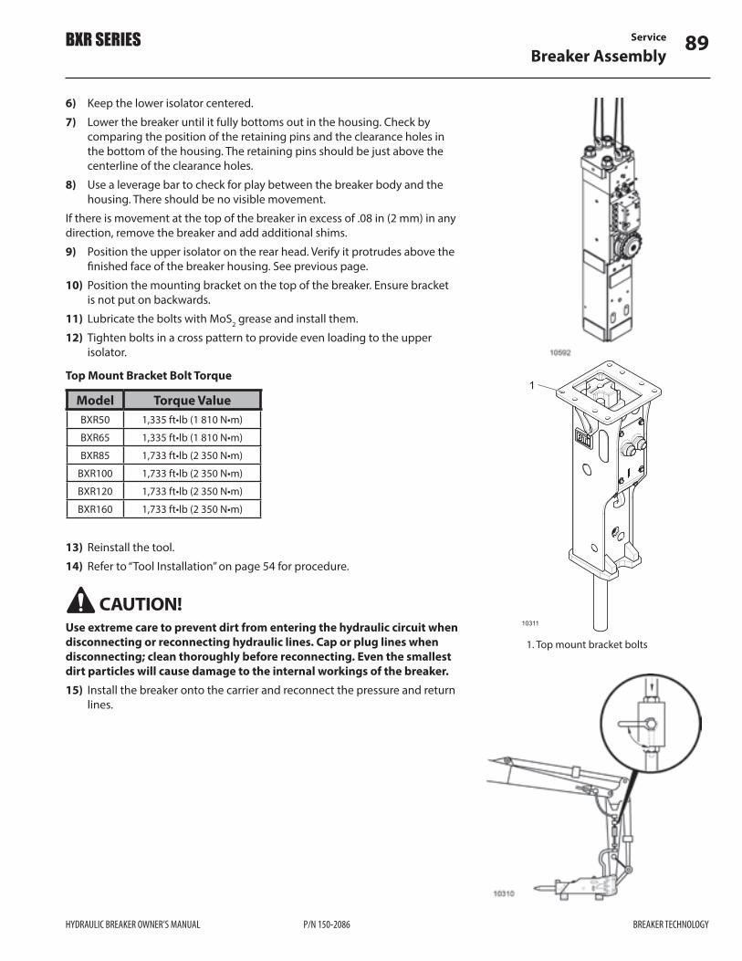
Service 89Breaker Assembly
HYDRAULIC BREAKER OWNER’S MANUAL P/N 150-2086 BREAKER TECHNOLOGY
BXR SERIES
6) Keep the lower isolator centered. 7) Lower the breaker until it fully bottoms out in the housing. Check by
comparing the position of the retaining pins and the clearance holes in the bottom of the housing. The retaining pins should be just above the centerline of the clearance holes.
8) Use a leverage bar to check for play between the breaker body and the housing. There should be no visible movement.
If there is movement at the top of the breaker in excess of .08 in (2 mm) in any direction, remove the breaker and add additional shims.9) Position the upper isolator on the rear head. Verify it protrudes above the
!nished face of the breaker housing. See previous page.10) Position the mounting bracket on the top of the breaker. Ensure bracket
is not put on backwards.11) Lubricate the bolts with MoS2 grease and install them.12) Tighten bolts in a cross pattern to provide even loading to the upper
isolator.
Top Mount Bracket Bolt Torque
Model Torque ValueBXR50 1,335 ft•lb (1 810 N•m)
BXR65 1,335 ft•lb (1 810 N•m)
BXR85 1,733 ft•lb (2 350 N•m)
BXR100 1,733 ft•lb (2 350 N•m)
BXR120 1,733 ft•lb (2 350 N•m)
BXR160 1,733 ft•lb (2 350 N•m)
13) Reinstall the tool. 14) Refer to “Tool Installation” on page 54 for procedure.
CAUTION! Use extreme care to prevent dirt from entering the hydraulic circuit when disconnecting or reconnecting hydraulic lines. Cap or plug lines when disconnecting; clean thoroughly before reconnecting. Even the smallest dirt particles will cause damage to the internal workings of the breaker.15) Install the breaker onto the carrier and reconnect the pressure and return
lines.
1
10311
1. Top mount bracket bolts

Service90Breaker Assembly
BREAKER TECHNOLOGY P/N 150-2086 HYDRAULIC BREAKER OWNER’S MANUAL
BXR SERIES
Start-upAir may have been introduced to the hydraulic circuit and may cause a malfunction. Warm the carrier hydraulic system up to operating temperature, then cycle the oil to remove the air:1) Lift the unit o$ the ground.2) Press the start button or pedal to !re the breaker momentarily.3) Continue to turn the breaker ON and OFF in this manner for 10 minutes.4) Work the breaker in soft material in short bursts for 10 minutes.5) Check for any loose bolts or oil leakage.
The breaker is now ready to operate.

Troubleshooting Guide 91Oil Leakage
HYDRAULIC BREAKER OWNER’S MANUAL P/N 150-2086 BREAKER TECHNOLOGY
BXR SERIES
Troubleshooting GuideOil LeakageIf oil leakage develops, it may not be necessary to replace parts. Check the following points in the table below before calling your BTI representative. A slight amount of oil seepage around the breaker connecting parts is normal during the !rst 200 hours of operation.
Area of Leakage Probable Cause Correction
AThe space between the tool and the bushing. Large amounts of oil coming out.BOil over the surface of the breaker.
Loose hydraulic hoses or adapters.
Damaged seals. Re-seal as necessary.
Check condition of hydraulic hoses and adapters. Tighten as necessary.
CControl valve cap bolts. Oil ooze after breaker
overhaul.Normal oozing of assembly lubricants.
DBetween control valve and surface of cylinder.
Oil ooze after breaker overhaul.
Normal oozing of assembly lubricants.
EJoining surface of cylinder and rear head.Oil oozing. New oil leaking.
Loose tie rod nut.Damaged o-ring.
Tighten tie rod.Replace damaged o-ring.
FJoining surface of cylinder and front head.New oil leaking.
GTwo-speed valve.Oil running down breaker.
Loose plugs on face of cylinder.Damaged seals.
Loose nut or damaged O-ring.
Tighten loose plugs.Replace damaged seals as necessary.
Tighten locking nut.Replace O-ring.

Troubleshooting Guide92Hydraulic Breaker
BREAKER TECHNOLOGY P/N 150-2086 HYDRAULIC BREAKER OWNER’S MANUAL
BXR SERIES
Does not hammer
Probable Cause Correction
Base carrier selector valve does not operate correctly.
Check connection from cab controls to selector valve.
Anti-blank !re has activated. Push breaker down on tool to disengage blank !re mode.
Poor performance of the hydraulic pump. Check pump outlet. Repair or replace.
Pressure relief valve set too low. Check relief settings and adjust.
Clogged or restricted hoses. Clean or replace.
Cushion chamber !lled with oil. Replace seals.
Seizure of breaker. Overhaul and replace worn parts.
Back-pressure too high in circuit. Find source causing increased back-pressure in return circuit and remove.
Control valve bolts loose. Tighten bolts to correct torque in a staggered pattern.
Check all ball valves. Open ball valve.
Hydraulic Breaker
Back-pressure too high in circuit. Find source causing increased back-pressure in return circuit and remove.
Does Not Impact
Probable Cause Correction
Temperature of the hydraulic oil is too low. Warm up the hydraulic excavator.
Pressure setting for the relief valve is too low. Set the relief valve to the correct pressure setting.
The nitrogen gas pressure in the cushion chamber is too high.
Adjust the nitrogen gas to the correct pressure.
Poor performance of the hydraulic pump on the excavator.
Have the hydraulic excavator manufacturer check the pump performance. If the performance is poor, repair or replace.

Troubleshooting Guide 93Hydraulic Breaker
HYDRAULIC BREAKER OWNER’S MANUAL P/N 150-2086 BREAKER TECHNOLOGY
BXR SERIES
Erratic hammering
Probable Cause Correction
Foreign matter in the breaker control valve. Disassemble and clean.
Seizure of piston and cylinder. Overhaul the breaker.
Hydraulic oil temperature is too high. Oil temperature must not exceed 158 °F (70 °C).
Insu#cient oil "ow and/or pressure. Check base carrier hydraulic system.
Clogged or restricted hoses, or pipes. Clean or replace.
Pressure too high in cushion chamber. Adjust pressure.
Too much grease in the impact chamber. Remove tool and clean out excess grease. Follow proper greasing instructions.
Excessive clearance between tool and tool bushing.
Check clearance and replace worn parts.
Not enough down force on the tool. Increase the down pressure acting on the tool.
Excess wear at top of tool. Remove and inspect the tool. Replace if necessary.
Back-pressure too high in circuit. Find source causing increased back-pressure in return circuit and remove.
Control valve bolts loose Tighten bolts to correct torque in a staggered pattern.
Back-pressure too high in circuit. Find source causing increased back-pressure in return circuit and remove.
Lack of Power
Probable Cause Correction
Insu#cient oil "ow or oil pressure. Check hydraulics of the base carrier.
Broken tool. Replace tool, check piston for damage.
Cushion chamber gas pressure is too low. Check and adjust.

Troubleshooting Guide94Hydraulic Breaker
BREAKER TECHNOLOGY P/N 150-2086 HYDRAULIC BREAKER OWNER’S MANUAL
BXR SERIES
Leakage
Probable Cause Correction
The space between the tool and bushing has large amounts of oil coming out.
Damaged seals. Re-seal as necessary.
Possible loose hoses or adapter !ttings cause oil over the surface of the breaker.
Check condition of hoses and !ttings, tighten as necessary.
Oil oozing after overhaul of breaker, between the control valve and surface of the cylinder.
Normal oozing of assembly lubricants.
Oil ooze after overhaul of breaker, between the joining surfaces of cylinder and rear head.
Loosen tie rod nuts, and retighten. Damaged o-ring, replace.
New oil leaking from surface between cylinder and front head.
Loosen plugs on face of the cylinder, then re-tighten. Damaged seals in the cylinder, replace as necessary.
Between the cylinder and hose adapter. Replace worn or damaged o-ring. Check and re-tighten the hose adapter to the speci!ed torque.
Leakage at stroke adjuster cap. Replace worn or damaged o-ring. Loosen the stroke adjuster cap, then re-tighten to speci!ed torque.
Leakage at pilot valve cap. Replace worn or damaged o-ring. Loosen the pilot valve cap, then re-tighten to speci!ed torque
Gas Leakage
Probable Cause Correction
Gas leakage from the gas valve. Replace worn or damaged seals. Check gas valve for damage repair or replace.
Leakage from gas valve body. Worn or damaged o-ring. Replace.
Gas leakage from between the cylinder and the cylinder cover.
Worn or damaged o-ring. Replace.
Control valve bolts loose Tighten bolts to correct torque in a staggered pattern.
Tie rods loose. Tighten to correct torque value in a cross pattern.

Troubleshooting Guide 95Hydraulic Breaker
HYDRAULIC BREAKER OWNER’S MANUAL P/N 150-2086 BREAKER TECHNOLOGY
BXR SERIES
Erratic Blows After Breaker has been Operating Normally
Probable Cause Correction
Seizure of piston and cylinder. Remove and inspect piston, and inside of cylinder body.
Regeneration Valve Sticking. Repair or replace control valve.
Relief valve for the excavator is set too low. Set the relief valve to correct pressure setting.
Poor performance of the hydraulic pump on the excavator.
Have the hydraulic excavator manufacturer check the pump performance. If the performance is poor, repair or replace.
Lack of down pressure on the tool. Operate the arm and bucket so that pressure is applied to the tool.Anti-blank !re is working.
Nitrogen gas pressure in the rear head is too low.
Adjust the nitrogen gas to the correct pressure.
Seizure of control valve. Repair or replace control valve.
Back-pressure too high in circuit. Find source causing increased back-pressure in return circuit and remove.
Control valve bolts loose Tighten bolts to correct torque in a staggered pattern.
Blows/min Decreased
Probable Cause Correction
Nitrogen gas pressure in the rear head is too high.
Adjust the nitrogen gas to the correct pressure.
Lack of down pressure on the tool. Operate the boom and bucket cylinders so that pressure is applied to the tool.
Pressure setting for the relief valve is too low. Set the relief valve to the correct pressure setting.

Troubleshooting Guide96Hydraulic Breaker
BREAKER TECHNOLOGY P/N 150-2086 HYDRAULIC BREAKER OWNER’S MANUAL
BXR SERIES
Tool Breaking
Probable Cause Correction
Tool Mushrooming
Probable Cause Correction
Abuse of tool and prying with tool. Apply down force in the direction of tool only. Check for excess play in arms, links, and pins.
Continuous hammering in one place. Use short bursts. Re-position breaker every 20 seconds.
Emulsi!cation of Oil
Probable Cause Correction
Oil contaminated with water. Locate source of water and repair. Replace oil.
Rapid Increase in Oil Temperature
Probable Cause Correction
Insu#cient oil cooling. Check oil cooler.
Insu#cient oil "ow. Check pump output.
Incorrect oil pressure. Check relief valve setting.
Blows/min Decreased
Probable Cause Correction
Clogged or restricted hoses, pipes. Investigate the blocked area and repair or replace.
Back-pressure too high in circuit. Find source causing increased back-pressure in return circuit and remove.
Poor performance of the hydraulic pump on the excavator.
Have the excavator manufacturer check the pump performance.

Troubleshooting Guide 97Breaker Tool
HYDRAULIC BREAKER OWNER’S MANUAL P/N 150-2086 BREAKER TECHNOLOGY
BXR SERIES
Breaker ToolNormal Breaker Tool WearWear depends on rock conditions. Hard, abrasive rock wears the tool down faster. Working in softer materials will keep the point shape longer.Blunt tools (A) will wear back 1/3 of the diameter to be shaped as shown. Moil and Chisel tools (B and C) will wear back 2 inches (51 mm) or more to be shaped as shown.As a general guide, this is considered normal wear and reasonable tool life.
Warranty claims are not accepted for normal wear.
Breaker Tool Fatigue FailuresMetal FatigueMetal fatigue is the sudden fracture of a component. This e$ect occurs on metal after a period of repeated cycles of stress. Normally, there will be no obvious warning. A crack forms without any visual change making it di#cult to detect the presence of growing cracks. Fractures usually start from small nicks or scratches or !llets that cause a localized concentration of stress. The fracture face itself normally appears as a semi-circular polished area with the remainder looking uneven and rough. The polished semi-circle is the fatigue area, originating from a damage mark or other stress event outside of the tool.The fatigue area spreads slowly into the tool, until the stress causes sudden failure to the section. Generally, the size of the fatigue area indicates the level of stress applied to the tool, i.e. the smaller the fatigue area, the higher the stress level. Once a fatigue crack begins, it takes less stress to make it grow.
1. Polished fatigue Rings
2. Stress Concentration Point
3. Rough Gray Area

Troubleshooting Guide98Breaker Tool
BREAKER TECHNOLOGY P/N 150-2086 HYDRAULIC BREAKER OWNER’S MANUAL
BXR SERIES
Cause and E$ect of FatigueIn normal operation, a cycle of compressive and tensile stresses "ow up and down the tool with each piston blow as the breaker !res.The main cause of increased tool fatigue stress is any side force applied during operation that bends the tool. Prying with the tool, using the incorrect working angle, or attempting to break ground using the pull of the carrier machine will shorten tool life and must be avoided. Anything that interferes with these normal stresses increases the risk of early tool fatigue failure.
Other Causes of Increased Tool fatigue StressBlank FiringBlank !ring is any situation where the breaker piston strikes the top of the tool, but the tool is not in proper contact with the material. This can happen when the tool slides o$ the work and also when breaking through thin concrete slabs or boulders.
ColdLow temperature makes the tool more susceptible to fatigue failure. Warm the tool !rst with moderate or light breaking.
Mechanical and Thermal DamageAny type of damage to the tool surface makes it more likely to su$er fatigue failure. Care must be taken to:
• Prevent scratches, gouges, weld marks. • Keep tool well lubricated. • Operate properly and avoid excessive bending of the tool.
Poor LubricationMetal to metal contact causes material pick up that can scrape deep damage marks. These will develop into fatigue cracks, causing tool failure. Ensure the tool shank is well lubricated before inserting into the tool holder. Molybdenum disul!de grease or BTI’s own brand of Chisel Paste (containing copper, graphite and silica) is recommended at 2 hour intervals.
• Make sure tool is pushed up fully inside the breaker. • Grease until clean grease runs freely from cavities.
CorrosionKeep spare tools well greased and sheltered from the weather when not in use. A rusty tool is more prone to fatigue failure.
Incorrect Breaking Angle
Prying with Breaker
Pulling with Carrier

Troubleshooting Guide 99Area of Typical Tool Failures
HYDRAULIC BREAKER OWNER’S MANUAL P/N 150-2086 BREAKER TECHNOLOGY
BXR SERIES
Area of Typical Tool FailuresGuide to Warranty ClaimsBTI tools are manufactured from top quality materials and heat-treated to produce a fatigue and wear resistant tool.When a tool fails to give satisfactory service life, a brief visual inspection usually reveals the cause.
• A tool metal “fatigue” failure generally occurs within 4 in (100 mm) above and below the face of the front head, or at the retainer pin "at.
• A less common failure area is about 8 in (200 mm) from the face of the front end, depending on the work the breaker is doing.
Typical fractures caused by excessive bending of the tool.
Fractures like this are not covered by warranty.
Typical fracture caused by prying with the tool while it was buried in the work piece.
Fractures like this are not covered by warranty.
1. Front Head
2. Retainer Pin Flat
3. High Risk Fatigue Area
4. Lower Risk Fatigue Area
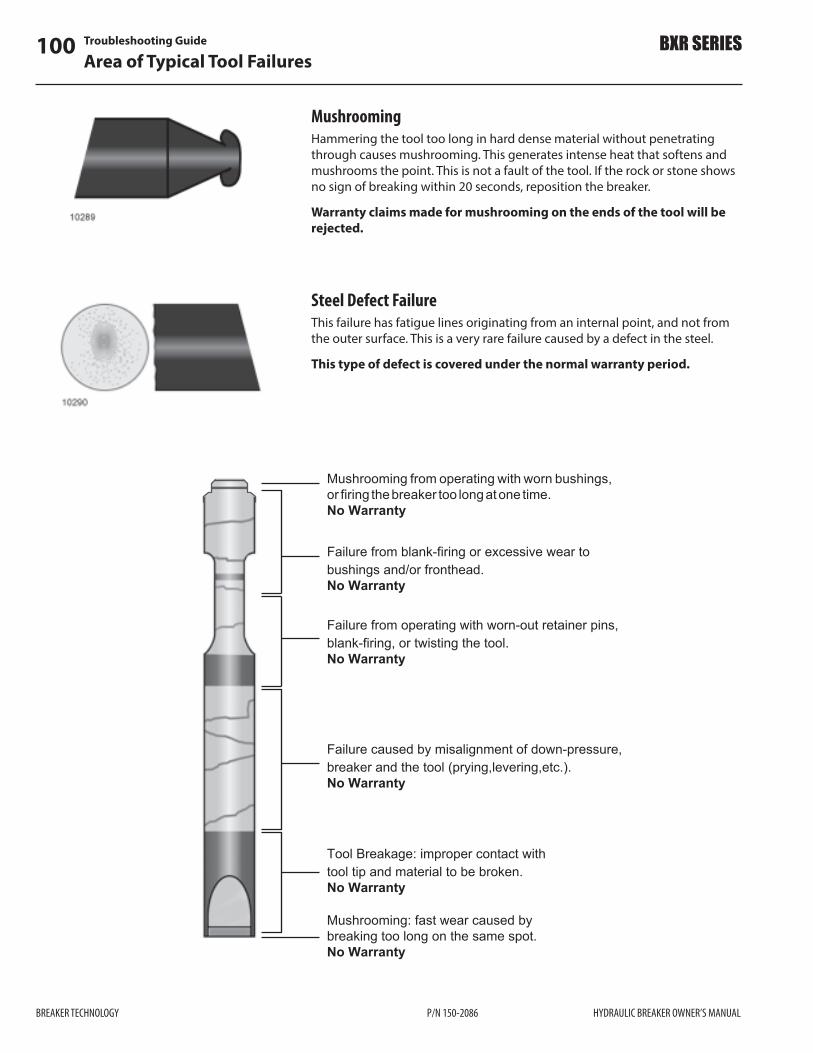
Troubleshooting Guide100Area of Typical Tool Failures
BREAKER TECHNOLOGY P/N 150-2086 HYDRAULIC BREAKER OWNER’S MANUAL
BXR SERIES
MushroomingHammering the tool too long in hard dense material without penetrating through causes mushrooming. This generates intense heat that softens and mushrooms the point. This is not a fault of the tool. If the rock or stone shows no sign of breaking within 20 seconds, reposition the breaker.
Warranty claims made for mushrooming on the ends of the tool will be rejected.
Steel Defect FailureThis failure has fatigue lines originating from an internal point, and not from the outer surface. This is a very rare failure caused by a defect in the steel.
This type of defect is covered under the normal warranty period.
Mushrooming from operating with worn bushings,or firing thebreaker too longatone time.No Warranty
Failure from blank-firing or excessive wear tobushings and/or fronthead.No Warranty
Failure from operating with worn-out retainer pins,blank-firing, or twisting the tool.No Warranty
Failure caused by misalignment of down-pressure,breaker and the tool (prying,levering,etc.).No Warranty
Tool Breakage: improper contact withtool tip and material to be broken.No Warranty
Mushrooming: fast wear caused bybreaking too long on the same spot.No Warranty

Removal and Storage 101Short-term Storage
HYDRAULIC BREAKER OWNER’S MANUAL P/N 150-2086 BREAKER TECHNOLOGY
BXR SERIES
Long-term StorageStoring the breaker over a week is considered Long-term Storage.
Breaker Stored Lying DownUse the following procedure:1) Release the cushion chamber gas pressure.2) Remove the tool and liberally grease the piston bottom, retaining pins
and inside the front head.3) Ensure inlet ports are open to allow piston to move up to the top.4) Push the piston up inside the breaker and reinstall the tool.5) Lay the breaker on wooden blocks (using your excavator). Mounting
bracket end should lie higher than the tool end.6) Cover the breaker with a tarp (waterproof if outdoors).
Removal and StorageCAUTION!
Use extreme care to prevent dirt from entering the hydraulic circuit when disconnecting or reconnecting hydraulic lines. Cap or plug lines when disconnecting; clean thoroughly before reconnecting. Even the smallest dirt particles will cause damage to the internal workings of the breaker.
Short-term StorageStoring your breaker up to a week is considered Short-term Storage. Follow this procedure:1) If shut-o$ valves are used with the breaker, turn them to the OFF position.2) Disconnect the pressure and return lines. Plug the lines and the breaker
ports to prevent contamination.3) Use your excavator to lay the breaker on wooden blocks with the
mounting bracket end lying higher than the tool end. Support the breaker before proceeding.
4) Remove the pins to disconnect the breaker from the carrier.5) Remove the tool and ensure the retaining pins, bushings and piston
bottom (inside breaker) are well greased.6) Reinstall the tool and cover the breaker with a tarp. Use a waterproof
cover if storing outdoors.

Removal and Storage102Long-term Storage
BREAKER TECHNOLOGY P/N 150-2086 HYDRAULIC BREAKER OWNER’S MANUAL
BXR SERIES
Initial Start-up after Storage
CAUTION! Use extreme care to prevent dirt from entering the hydraulic circuit when disconnecting or reconnecting hydraulic lines. Cap or plug lines when disconnecting; clean thoroughly before reconnecting. Even the smallest dirt particles will cause damage to the internal workings of the breaker.Storage can introduce air into the hydraulic circuit. If air is present in the hydraulic circuit during operation, it may cause a malfunction.Circulating the oil will remove air and other foreign substances from the system. If the breaker was stored lying down, seals can deform. Follow these steps to circulate the hydraulic oil, and correct these problems:1) First, recharge cushion chamber with nitrogen gas.With the breaker mounted and oil warmed to operating temperatures:2) Lift the unit of the ground.3) Press the Start button or pedal to !re the breaker momentarily.4) Continue to turn the breaker ON and OFF in this manner for ten minutes.The breaker is now ready to be put into service.
Breaker Stored Standing UpIf the breaker is to be stored standing up, place in a safety stand. Use the following procedure: 1) Release the cushion chamber gas pressure.2) Remove the tool and liberally grease the piston bottom, retaining pins
and inside the front head.3) Ensure inlet ports are open to allow piston to move up to top.4) Reinstall the tool and place the breaker in the vertical stand. This will
allow the breaker’s weight to push the tool and piston up inside the breaker.
5) Cover the breaker with a tarp (waterproof if outdoors).

NOTES
103
HYDRAULIC BREAKER OWNER’S MANUAL P/N 150-2086 BREAKER TECHNOLOGY
BXR SERIES

Speci!cations104Model BXR50
BREAKER TECHNOLOGY P/N 150-2086 HYDRAULIC BREAKER OWNER’S MANUAL
BXR SERIES
Speci!cationsModel BXR50
Energy Class 5,000 ft•lb (6 800 joule)
Operating Weight 4,200 lb (1 905 kg)
Tool Diameter 5.5 in (140 mm)
Exposed Tool Length 25.1 in (635 mm)
Recommended Carrier Weight 39,700–77,200 lb(18–35 tonne)
Relief Pressure Setting (See note) 4,000 psi (275 bar)
Cushion Chamber Nitrogen Pressure 145 psi (10 bar)
Accumulator Nitrogen Pressure 754 psi (52 bar)
Hydraulic Hose Size 1 in JIC (25 mm)
Remote Grease Connection 1/4 in NPT
Remote Air Breather Connection 1/2 in BSPT
Oil Regeneration System Standard
Anti-blank Fire Interlock Standard
Two-speed Control Operator Controlled Hydraulic Pilot
Low Noise Box Housing Standard
Severe Duty Wear Kit Optional
Carrier Mounted Automatic Greasing System Optional
Breaker Mounted Auto Greasing System Optional
Tool Types Blunt / Moil / Chisel
APPROX.103 1/4''
(2622 mm)
72''(1829 mm)
21 1/8''(537 mm)
15 1/2''(394 mm)
10550
NOTE: Relief valve setting is based on 100 psi (7 bar) back pressure. For higher back pressures, raise the relief valve setting accordingly. Consult BTI if the back pressure is greater than 450 psi (30 bar).

Speci!cations 105Model BXR50
HYDRAULIC BREAKER OWNER’S MANUAL P/N 150-2086 BREAKER TECHNOLOGY
BXR SERIES
BXR50 Breaker Con!gured With Oil Regeneration System On
Pressure Ori!ce Diameter 16 mm
Choke Ori!ce Diameter 9,5 mm
Nitrogen Pressure In Rear Head with Regen 145 psi (10 bar)
Maximum Flow Rate with Regen 53 gpm (200 lpm)
Minimum Flow Rate with Regen (75% Of Max) 40 gpm (150 lpm)
Operating Pressure at Full Flow with Regen Design for 35 Bar Pressure Rise at Maximum Regen
2,250–2,755 psi (155–190 bar)
Low Speed BPM at Max Flow @ 85% Vol E" – No Regen 512
Low Speed BPM at Max Flow @ 85% Vol E" and 15% Regen Speed
589
High Speed BPM at Max Flow 85% Vol E" – No Regen 699
High Speed BPM at Max Flow @ 85% Vol E" and 15% Regen
804
Low Speed BPM at Low Flow @ 85% Vol E" – No Regen 387
High Speed BPM at Low Flow @ 85% Vol E" – No Regen 445
BXR50 Breaker Con!gured for Oil Regeneration Mode OFF With Spool Locked Out or in By-pass Mode
Pressure Ori!ce Diameter 16 mm
Choke Ori!ce Diameter 9,5 mm
Nitrogen Pressure in Rear Head – Regen Lockout 160 psi (11 bar)
Maximum Flow Rate – Regen Lockout 58 gpm (220 lpm)
Minimum Flow Rate without Regen (75% Of Max) 44 gpm (165 lpm)
Operating Pressure at Full Flow Regen Lockout. There is No Pressure Rise – Regen Lockout
2,250–2,755 psi (155–190 bar)
Low Speed BPM at Max Flow @ 85% Vol E" Regen Lockout
561
High Speed BPM at Max Flow @ 85% Vol E" Regen Lockout
766
Low Speed BPM at Low Flow @ 85% Vol E" Regen Lockout
425
High Speed BPM at Low Flow @ 85% Vol E" Regen Lockout
581
BXR50 Mounting Plate
Regen = Oil RegenerationVol E$ = Volumetric E#ciency

Speci!cations106Model BXR65
BREAKER TECHNOLOGY P/N 150-2086 HYDRAULIC BREAKER OWNER’S MANUAL
BXR SERIES
Model BXR65
APPROX.112 11/16''
(2863 mm)
26 3/16''(665 mm)
76 3/8''(1940 mm)
15 3/4''(400 mm)
10552
Energy Class 6,500 ft•lb (8 800 joule)
Operating Weight 4,880 lb (2 200 kg)
Tool Diameter 6 in (150 mm)
Exposed Tool Length 26.2 in (665 mm)
Recommended Carrier Weight 41,900–92,600 lb(19–42 tonne)
Relief Pressure Setting (see note) 4,000 psi (275 bar)
Cushion Chamber Nitrogen Pressure 145 psi (10 bar)
Accumulator Nitrogen Pressure 754 psi (52 bar)
Hydraulic Hose Size 1 in JIC (25 mm)
Remote Grease Connection 1/4 in NPT
Remote Air Breather Connection 1/2 in BSPT
Oil Regeneration System Standard
Anti-blank Fire Interlock Standard
Two-speed Control Operator Controlled Hydraulic Pilot
Low Noise Box Housing Standard
Severe Duty Wear Kit Optional
Carrier Mounted Automatic Greasing System
Optional
Breaker Mounted Auto Greasing System Optional
Tool Types Blunt / Moil / Chisel
NOTE: Relief valve setting is based on 100 psi (7 bar) back pressure. For higher back pressures, raise the relief valve setting accordingly. Consult BTI if the back pressure is greater than 450 psi (30 bar).

Speci!cations 107Model BXR65
HYDRAULIC BREAKER OWNER’S MANUAL P/N 150-2086 BREAKER TECHNOLOGY
BXR SERIES
BXR65 Mounting Plate
BXR65 Breaker Con!gured With Oil Regeneration System On
Pressure Ori!ce Diameter 16 mm
Choke Ori!ce Diameter 10 mm
Nitrogen Pressure In Rear Head with Regen 145 psi (10 bar)
Maximum Flow Rate with Regen 56 gpm (210 lpm)
Minimum Flow Rate with Regen (75% Of Max) 42 gpm (158 lpm)
Operating Pressure at Full Flow with Regen Design for 35 Bar Pressure Rise at Maximum Regen
2,250–2,755 psi (155–190 bar)
Low Speed BPM at Max Flow @ 85% Vol E" – No Regen 447
Low Speed BPM at Max Flow @ 85% Vol E" and 15% Regen Speed
514
High Speed BPM at Max Flow 85% Vol E" – No Regen 595
High Speed BPM at Max Flow @ 85% Vol E" and 15% Regen
684
Low Speed BPM at Low Flow @ 85% Vol E" – No Regen 335
High Speed BPM at Low Flow @ 85% Vol E" – No Regen 385
BXR65 Breaker Con!gured for Oil Regeneration Mode OFF With Spool Locked Out or in By-pass Mode
Pressure Ori!ce Diameter 16 mm
Choke Ori!ce Diameter 10 mm
Nitrogen Pressure in Rear Head – Regen Lockout 160 psi (11 bar)
Maximum Flow Rate – Regen Lockout 61 gpm (230 lpm)
Minimum Flow Rate without Regen (75% Of Max) 46 gpm (172,5 lpm)
Operating Pressure at Full Flow Regen Lockout. There is No Pressure Rise – Regen Lockout
2,250–2,755 psi (155–190 bar)
Low Speed BPM at Max Flow @ 85% Vol E" Regen Lockout
487
High Speed BPM at Max Flow @ 85% Vol E" Regen Lockout
648
Low Speed BPM at Low Flow @ 85% Vol E" Regen Lockout
367
High Speed BPM at Low Flow @ 85% Vol E" Regen Lockout
488
Regen = Oil RegenerationVol E$ = Volumetric E#ciency

Speci!cations108Model BXR85
BREAKER TECHNOLOGY P/N 150-2086 HYDRAULIC BREAKER OWNER’S MANUAL
BXR SERIES
Model BXR85
APPROX.127 9/16''
(3241 mm)
82 3/4''(2102 mm)
29 3/8''(746 mm)
18 1/8''(460 mm)
10554
Energy Class 8,500 ft•lb (11 500 joule)
Operating Weight 6,500 lb (2 950 kg)
Tool Diameter 6.3 in (160 mm)
Exposed Tool Length 29 in (745 mm)
Recommended Carrier Weight 61,700–105,800 lb(28–48 tonne)
Relief Pressure Setting (see note) 4,000 psi (275 bar)
Cushion Chamber Nitrogen Pressure 131 psi (9 bar)
Accumulator Nitrogen Pressure 754 psi (52 bar)
Hydraulic Hose Size 1 1/4 in JIC (32 mm)
Remote Grease Connection 1/4 in NPT
Remote Air Breather Connection 1/2 in BSPT
Oil Regeneration System Standard
Anti-blank Fire Interlock Standard
Two-speed Control Operator Controlled Hydraulic Pilot
Low Noise Box Housing Standard
Severe Duty Wear Kit Optional
Carrier Mounted Automatic Greasing System Optional
Breaker Mounted Auto Greasing System Optional
Tool Types Blunt / Moil / Chisel
NOTE: Relief valve setting is based on 100 psi (7 bar) back pressure. For higher back pressures, raise the relief valve setting accordingly. Consult BTI if the back pressure is greater than 450 psi (30 bar).

Speci!cations 109Model BXR85
HYDRAULIC BREAKER OWNER’S MANUAL P/N 150-2086 BREAKER TECHNOLOGY
BXR SERIES
BXR85 Mounting Plate
BXR85 Breaker Con!gured With Oil Regeneration System On
Pressure Ori!ce Diameter 16 mm
Choke Ori!ce Diameter 11,5 mm
Nitrogen Pressure In Rear Head with Regen 131 psi (9 bar)
Maximum Flow Rate with Regen 61 gpm (230 lpm)
Minimum Flow Rate with Regen (75% Of Max) 46 gpm (173 lpm)
Operating Pressure at Full Flow with Regen Design for 35 Bar Pressure Rise at Maximum Regen
2,250–2,755 psi (155–190 bar)
Low Speed BPM at Max Flow @ 85% Vol E" – No Regen 378
Low Speed BPM at Max Flow @ 85% Vol E" and 15% Regen Speed
435
High Speed BPM at Max Flow 85% Vol E" – No Regen 503
High Speed BPM at Max Flow @ 85% Vol E" and 15% Regen
578
Low Speed BPM at Low Flow @ 85% Vol E" – No Regen 285
High Speed BPM at Low Flow @ 85% Vol E" – No Regen 328
BXR85 Breaker Con!gured for Oil Regeneration Mode OFF With Spool Locked Out or in By-pass Mode
Pressure Ori!ce Diameter 16 mm
Choke Ori!ce Diameter 11,5 mm
Nitrogen Pressure in Rear Head – Regen Lockout 160 psi (11 bar)
Maximum Flow Rate – Regen Lockout 66 gpm (250 lpm)
Minimum Flow Rate without Regen (75% Of Max) 50 gpm (187,5 lpm)
Operating Pressure at Full Flow Regen Lockout. There is No Pressure Rise – Regen Lockout
2,250–2,755 psi (155–190 bar)
Low Speed BPM at Max Flow @ 85% Vol E" Regen Lockout
426
High Speed BPM at Max Flow @ 85% Vol E" Regen Lockout
567
Low Speed BPM at Low Flow @ 85% Vol E" Regen Lockout
322
High Speed BPM at Low Flow @ 85% Vol E" Regen Lockout
428
Regen = Oil RegenerationVol E$ = Volumetric E#ciency

Speci!cations110Model BXR100
BREAKER TECHNOLOGY P/N 150-2086 HYDRAULIC BREAKER OWNER’S MANUAL
BXR SERIES
Model BXR100
APPROX.133 13/16''
(3399 mm)
88 3/16''(2240 mm)
30 3/8''(771 mm)
18 1/2''(460 mm)
10556
Energy Class 10,000 ft•lb (13 500 joule)
Operating Weight 7,800 lb (3 550 kg)
Tool Diameter 6.7 in (170 mm)
Exposed Tool Length 30 in (770 mm)
Recommended Carrier Weight 75,000–150,000 lb(34–68 tonne)
Relief Pressure Setting (see note) 4,000 psi (275 bar)
Cushion Chamber Nitrogen Pressure 145 psi (10 bar)
Accumulator Nitrogen Pressure 754 psi (52 bar)
Hydraulic Hose Size 1 1/4 in JIC(32 mm)
Remote Grease Connection 1/4 in NPT
Remote Air Breather Connection 1/2 in BSPT
Oil Regeneration System Standard
Anti-blank Fire Interlock Standard
Two-speed Control Operator Controlled Hydraulic Pilot
Low Noise Box Housing Standard
Severe Duty Wear Kit Optional
Carrier Mounted Automatic Greasing System Optional
Breaker Mounted Auto Greasing System Optional
Tool Types Blunt / Moil / Chisel
NOTE: Relief valve setting is based on 100 psi (7 bar) back pressure. For higher back pressures, raise the relief valve setting accordingly. Consult BTI if the back pressure is greater than 450 psi (30 bar).

Speci!cations 111Model BXR100
HYDRAULIC BREAKER OWNER’S MANUAL P/N 150-2086 BREAKER TECHNOLOGY
BXR SERIES
BXR100 Mounting Plate
BXR100 Breaker Con!gured With Oil Regeneration System On
Pressure Ori!ce Diameter 16 mm
Choke Ori!ce Diameter 12,5 mm
Nitrogen Pressure In Rear Head with Regen 145 psi (10 bar)
Maximum Flow Rate with Regen 82 gpm (310 lpm)
Minimum Flow Rate with Regen (75% Of Max) 62 gpm (233 lpm)
Operating Pressure at Full Flow with Regen Design for 35 Bar Pressure Rise at Maximum Regen
2,250–2,755 psi (155–190 bar)
Low Speed BPM at Max Flow @ 85% Vol E" – No Regen 419
Low Speed BPM at Max Flow @ 85% Vol E" and 15% Regen Speed
482
High Speed BPM at Max Flow 85% Vol E" – No Regen 553
High Speed BPM at Max Flow @ 85% Vol E" and 15% Regen
636
Low Speed BPM at Low Flow @ 85% Vol E" – No Regen 317
High Speed BPM at Low Flow @ 85% Vol E" – No Regen 365
BXR100 Breaker Con!gured for Oil Regeneration Mode OFF With Spool Locked Out or in By-pass Mode
Pressure Ori!ce Diameter 16 mm
Choke Ori!ce Diameter 12,5 mm
Nitrogen Pressure in Rear Head – Regen Lockout 160 psi (11 bar)
Maximum Flow Rate – Regen Lockout 90 gpm (340 lpm)
Minimum Flow Rate without Regen (75% Of Max) 67 gpm (255 lpm)
Operating Pressure at Full Flow Regen Lockout. There is No Pressure Rise – Regen Lockout
2,250–2,755 psi (155–190 bar)
Low Speed BPM at Max Flow @ 85% Vol E" Regen Lockout
460
High Speed BPM at Max Flow @ 85% Vol E" Regen Lockout
607
Low Speed BPM at Low Flow @ 85% Vol E" Regen Lockout
342
High Speed BPM at Low Flow @ 85% Vol E" Regen Lockout
451
Regen = Oil RegenerationVol E$ = Volumetric E#ciency

Speci!cations112Model BXR120
BREAKER TECHNOLOGY P/N 150-2086 HYDRAULIC BREAKER OWNER’S MANUAL
BXR SERIES
Model BXR120
APPROX.137 7/8''
(3502 mm)
91 1/16''(2314 mm)
31 13/16''(807 mm)
18 7/8''(480 mm)
10558
Energy Class 12,000 ft•lb (16 300 joule)
Operating Weight 9,050 lb (4 100 kg)
Tool Diameter 7.1 in (180 mm)
Exposed Tool Length 31 in (810 mm)
Recommended Carrier Weight 92,600–178,600 lb(42–81 tonne)
Relief Pressure Setting (see note) 4,000 psi (275 bar)
Cushion Chamber Nitrogen Pressure 159 psi (11 bar)
Accumulator Nitrogen Pressure 754 psi (52 bar)
Hydraulic Hose Size 1 1/4 in JIC (32 mm)
Remote Grease Connection 1/4 in NPT
Remote Air Breather Connection 1/2 in BSPT
Oil Regeneration System Standard
Anti-blank Fire Interlock Standard
Two-speed Control Operator Controlled Hydraulic Pilot
Low Noise Box Housing Standard
Severe Duty Wear Kit Optional
Carrier Mounted Automatic Greasing System
Optional
Breaker Mounted Auto Greasing System Optional
Tool Types Blunt / Moil / Chisel
NOTE: Relief valve setting is based on 100 psi (7 bar) back pressure. For higher back pressures, raise the relief valve setting accordingly. Consult BTI if the back pressure is greater than 450 psi (30 bar).

Speci!cations 113Model BXR120
HYDRAULIC BREAKER OWNER’S MANUAL P/N 150-2086 BREAKER TECHNOLOGY
BXR SERIES
BXR120 Mounting Plate
BXR120 Breaker Con!gured With Oil Regeneration System On
Pressure Ori!ce Diameter 22 mm
Choke Ori!ce Diameter 12,5 mm
Nitrogen Pressure In Rear Head with Regen 160 psi (11 bar)
Maximum Flow Rate with Regen 106 gpm (400 lpm)
Minimum Flow Rate with Regen (75% Of Max) 79 gpm (300 lpm)
Operating Pressure at Full Flow with Regen Design for 35 Bar Pressure Rise at Maximum Regen
2,250–2,755 psi (155–190 bar)
Low Speed BPM at Max Flow @ 85% Vol E" – No Regen 412
Low Speed BPM at Max Flow @ 85% Vol E" and 15% Regen Speed
474
High Speed BPM at Max Flow 85% Vol E" – No Regen 515
High Speed BPM at Max Flow @ 85% Vol E" and 15% Regen
592
Low Speed BPM at Low Flow @ 85% Vol E" – No Regen 308
High Speed BPM at Low Flow @ 85% Vol E" – No Regen 354
BXR120 Breaker Con!gured for Oil Regeneration Mode OFF With Spool Locked Out or in By-pass Mode
Pressure Ori!ce Diameter 16 mm
Choke Ori!ce Diameter 12,5 mm
Nitrogen Pressure in Rear Head – Regen Lockout 160 psi (11 bar)
Maximum Flow Rate – Regen Lockout 106 gpm (400 lpm)
Minimum Flow Rate without Regen (75% Of Max) 79 gpm (300 lpm)
Operating Pressure at Full Flow Regen Lockout. There is No Pressure Rise – Regen Lockout
1,810–2,320 psi (125–160 bar)
Low Speed BPM at Max Flow @ 85% Vol E" Regen Lockout
413
High Speed BPM at Max Flow @ 85% Vol E" Regen Lockout
516
Low Speed BPM at Low Flow @ 85% Vol E" Regen Lockout
308
High Speed BPM at Low Flow @ 85% Vol E" Regen Lockout
385
Regen = Oil RegenerationVol E$ = Volumetric E#ciency
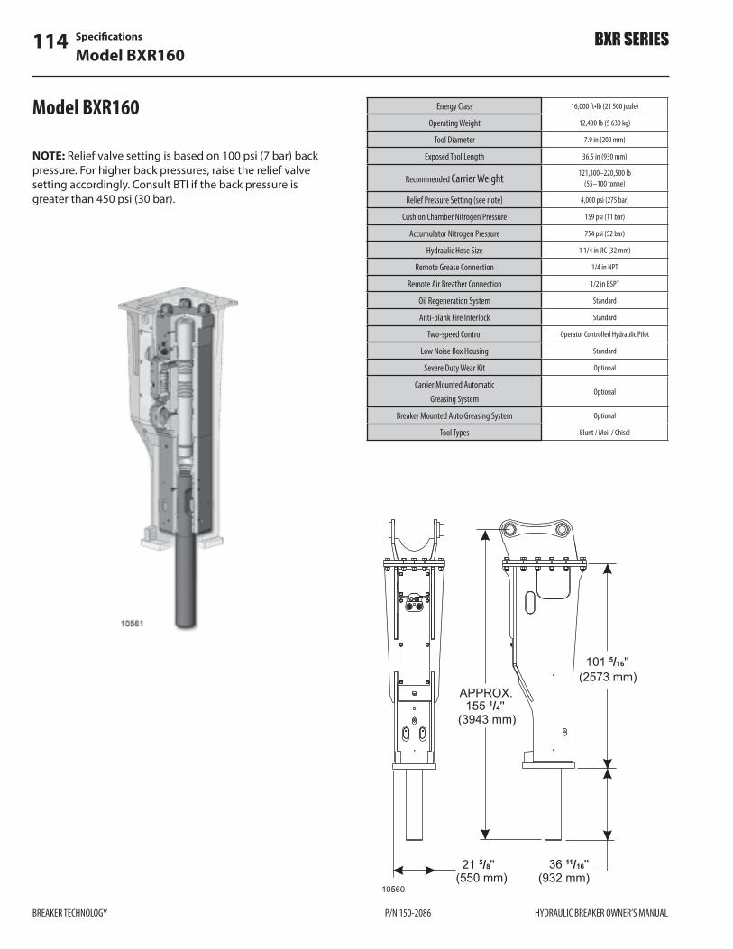
Speci!cations114Model BXR160
BREAKER TECHNOLOGY P/N 150-2086 HYDRAULIC BREAKER OWNER’S MANUAL
BXR SERIES
Model BXR160
APPROX.155 1/4''
(3943 mm)
101 5/16''(2573 mm)
36 11/16''(932 mm)
21 5/8''(550 mm)
10560
Energy Class 16,000 ft•lb (21 500 joule)
Operating Weight 12,400 lb (5 630 kg)
Tool Diameter 7.9 in (200 mm)
Exposed Tool Length 36.5 in (930 mm)
Recommended Carrier Weight 121,300–220,500 lb(55–100 tonne)
Relief Pressure Setting (see note) 4,000 psi (275 bar)
Cushion Chamber Nitrogen Pressure 159 psi (11 bar)
Accumulator Nitrogen Pressure 754 psi (52 bar)
Hydraulic Hose Size 1 1/4 in JIC (32 mm)
Remote Grease Connection 1/4 in NPT
Remote Air Breather Connection 1/2 in BSPT
Oil Regeneration System Standard
Anti-blank Fire Interlock Standard
Two-speed Control Operator Controlled Hydraulic Pilot
Low Noise Box Housing Standard
Severe Duty Wear Kit Optional
Carrier Mounted Automatic Greasing System
Optional
Breaker Mounted Auto Greasing System Optional
Tool Types Blunt / Moil / Chisel
NOTE: Relief valve setting is based on 100 psi (7 bar) back pressure. For higher back pressures, raise the relief valve setting accordingly. Consult BTI if the back pressure is greater than 450 psi (30 bar).

Speci!cations 115Model BXR160
HYDRAULIC BREAKER OWNER’S MANUAL P/N 150-2086 BREAKER TECHNOLOGY
BXR SERIES
BXR160 Mounting Plate
BXR160 Breaker Con!gured for Oil Regeneration Mode OFF With Spool Locked Out or in By-pass Mode
Pressure Ori!ce Diameter 16 mm
Choke Ori!ce Diameter 12,5 mm
Nitrogen Pressure in Rear Head – Regen Lockout 160 psi (11 bar)
Maximum Flow Rate – Regen Lockout 119 gpm (450 lpm)
Minimum Flow Rate without Regen (75% Of Max) 89 gpm (337,5 lpm)
Operating Pressure at Full Flow Regen Lockout. There is No Pressure Rise – Regen Lockout
1,810–2,320 psi (125–160 bar)
Low Speed BPM at Max Flow @ 85% Vol E" Regen Lockout
318
High Speed BPM at Max Flow @ 85% Vol E" Regen Lockout
413
Low Speed BPM at Low Flow @ 85% Vol E" Regen Lockout
238
High Speed BPM at Low Flow @ 85% Vol E" Regen Lockout
309
Regen = Oil RegenerationVol E$ = Volumetric E#ciency
BXR160 Breaker Con!gured With Oil Regeneration System On
Pressure Ori!ce Diameter 22 mm
Choke Ori!ce Diameter 12,5 mm
Nitrogen Pressure In Rear Head with Regen 160 psi (11 bar)
Maximum Flow Rate with Regen 119 gpm (450 lpm)
Minimum Flow Rate with Regen (75% Of Max) 89 gpm (338 lpm)
Operating Pressure at Full Flow with Regen Design for 35 Bar Pressure Rise at Maximum Regen
2,250–2,755 psi (155–190 bar)
Low Speed BPM at Max Flow @ 85% Vol E" – No Regen 318
Low Speed BPM at Max Flow @ 85% Vol E" and 15% Regen Speed
366
High Speed BPM at Max Flow 85% Vol E" – No Regen 413
High Speed BPM at Max Flow @ 85% Vol E" and 15% Regen
475
Low Speed BPM at Low Flow @ 85% Vol E" – No Regen 238
High Speed BPM at Low Flow @ 85% Vol E" – No Regen 274

Torque Speci!cations116BXR50
BREAKER TECHNOLOGY P/N 150-2086 HYDRAULIC BREAKER OWNER’S MANUAL
BXR SERIES
Torque Speci!cations
BXR50NOTE: All Torques shown in lubricated state.T.F.F.T. – Turns From Finger Tight. Tighten item by hand, then wrench-tighten to number of turns shown from !nger tight.LUBRICATED – cleaned, dry bolts lubricated with standard medium viscosity machine oil.
ITEM DESCRIPTION - SIZE TORQUEft•lb (N•m) LUBRICANT
AA TIE ROD- ROLLED THREAD – R48 100 (136) MoS2 LUBRICATED
A TIE ROD NUT- ROLLED THREAD – R48 1,808 (2 452) MoS2 LUBRICATED
B GAS VALVE ASSEMBLY – BSPP - PF 1/4 26 (35) LUBRICATED
C GREASE ZERK & ADAPTER – PT 1/4 2-3 T.F.F.T. PIPE SEALANT
D AIR VALVE ASSEMBLY – PT 1/2 2-3 T.F.F.T. PIPE SEALANT
E PRESSURE PLUG – M42 x P1.5 266 (360) LUBRICATED
F TANK PORT PLUG – M30 x P1.5 180 (245) LUBRICATED
G HEX PLUG – PF 3/8 52 (70) LUBRICATED
H RETURN ADAPTER - BSPP – PF 1-1/4 332 (450) LUBRICATED
J PRESSURE ADAPTER – BSPP – PF 1-1/4
332 (450) LUBRICATED
K HEX SOCKET PLUG - BSPP – PF1/8 13 (18) LUBRICATED
L GREASE ZERK ADAPTER – BSPP - PF 1
229 (310) LUBRICATED
M STROKE ADJUSTER ASSY – BSPP - PF 1
229 (310) LUBRICATED
N REGENERATION VALVE ASSY – BSPP -PF 3/4
170 (230) LUBRICATED
O HEX SOCKET PLUG – BSPP - PF 1/4 26 (35) LUBRICATED
P VALVE TENSION BOLT – M22 x P1.5 450 (610) MoS2 LUBRICATED
Q VALVE CAP TENSION BOLT – M22 x P1.5
450 (610) MoS2 LUBRICATED
R CHOKE PLUG & AIR VALVE ADAPTOR – PT 3/4 2-3 T.F.F.T. PIPE SEALANT
S ACCUMULATOR COVER CAPSCREW – M18 x P1.5
289 (391) LUBRICATED
T ACCUMULATOR CAPSCREW – M24 x P2.0
738 (1 000) LUBRICATED
V DIFFUSER NUT – M20 x P1.5 - LOWER TORQUE 434 (588) LUBRICATED
W DIFFUSER NUT – M20 x P1.5 - HIGHER TORQUE
470 (687) LUBRICATED
X BRACKET BOLT – 1-1/4 UNC or (M33) 1,335 (1 810) MoS2 LUBRICATED
Y HEX CAPSCREW – M16 x P2.0 108 (146) MoS2 LUBRICATED
Z HEX SOCKET PLUG – BSPP - PF 1/2 66 (90) LUBRICATED

Torque Speci!cations 117BXR50
HYDRAULIC BREAKER OWNER’S MANUAL P/N 150-2086 BREAKER TECHNOLOGY
BXR SERIES
BXR50

Torque Speci!cations118BXR65
BREAKER TECHNOLOGY P/N 150-2086 HYDRAULIC BREAKER OWNER’S MANUAL
BXR SERIES
ITEM DESCRIPTION - SIZE TORQUEft•lb (N•m) LUBRICANT
AA TIE ROD- ROLLED THREAD – R48 100 (136) MoS2 LUBRICATED
A TIE ROD NUT- ROLLED THREAD –R48 1,808 (2 452) MoS2 LUBRICATED
B GAS VALVE ASSEMBLY – BSPP - PF 1/4 26 (35) LUBRICATED
C GREASE ZERK & ADAPTER – PT 1/4 2-3 T.F.F.T. PIPE SEALANT
D AIR VALVE ASSEMBLY – PT 1/2 2-3 T.F.F.T. PIPE SEALANT
E PRESSURE PLUG – M42 x P1.5 266 (360) LUBRICATED
F TANK PORT PLUG – M30 x P1.5 180 (245) LUBRICATED
G HEX PLUG – PF 3/8 52 (70) LUBRICATED
H RETURN ADAPTER - BSPP – PF 1-1/4 332 (450) LUBRICATED
J PRESSURE ADAPTER - BSPP – PF 1-1/4 332 (450) LUBRICATED
K HEX SOCKET PLUG - BSPP – PF1/8 13 (18) LOCTITE
L GREASE ZERK ADAPTER – BSPP - PF 1 229 (310) LUBRICATED
M STROKE ADJUSTER ASSY – BSPP - PF 1 229 (310) LUBRICATED
N REGENERATION VALVE ASSY – BSPP -PF 3/4 170 (230) LUBRICATED
O HEX SOCKET PLUG – BSPP - PF 1/4 26 (35) LUBRICATED
P VALVE TENSION BOLT – M24 x P2.0 575 (780) MoS2 LUBRICATED
Q VALVE CAP TENSION BOLT – M24 x P2.0 575 (780) MoS2 LUBRICATED
R CHOKE PLUG & AIR VALVE ADAPTOR – PT 3/4 2-3 T.F.F.T. PIPE SEALANT
S ACCUMULATOR COVER CAPSCREW – M20 x P2.0
398 (539) LUBRICATED
T ACCUMULATOR CAPSCREW – M30 x P2.0 1,364 (1 848) LUBRICATED
V DIFFUSER NUT – M20 x P1.5 - LOWER TORQUE
434 (588) LUBRICATED
W DIFFUSER NUT – M20 x P1.5 - HIGHER TORQUE
470 (637) LUBRICATED
X BRACKET BOLT – 1-1/4 UNC or (M33) 1,335 (1 810) MoS2 LUBRICATED
Y HEX CAPSCREW – M16 x P2.0 108 (146) MoS2 LUBRICATED
Z HEX SOCKET PLUG – BSPP - PF 1/2 66 (90) LUBRICATED
BXR65NOTE: All Torques shown in lubricated state.T.F.F.T. – Turns From Finger Tight. Tighten item by hand, then wrench-tighten to number of turns shown from !nger tight.LUBRICATED – cleaned, dry bolts lubricated with standard medium viscosity machine oil.

Torque Speci!cations 119BXR65
HYDRAULIC BREAKER OWNER’S MANUAL P/N 150-2086 BREAKER TECHNOLOGY
BXR SERIES
BXR65

Torque Speci!cations120BXR85
BREAKER TECHNOLOGY P/N 150-2086 HYDRAULIC BREAKER OWNER’S MANUAL
BXR SERIES
ITEM DESCRIPTION - SIZE TORQUEft•lb (N•m) LUBRICANT
AA TIE ROD- ROLLED THREAD – R55 100 (136) MoS2 LUBRICATED
A TIE ROD NUT- ROLLED THREAD – R55 2,604 (3 528) MoS2 LUBRICATED
B GAS VALVE ASSEMBLY – BSPP - PF 1/4 26 (35) LUBRICATED
C GREASE ZERK & ADAPTER – PT 1/4 2-3 T.F.F.T. PIPE SEALANT
D AIR VALVE ASSEMBLY – PT 1/2 2-3 T.F.F.T. PIPE SEALANT
E PRESSURE PLUG – M48 x P1.5 310 (420) LUBRICATED
F TANK PORT PLUG – M30 x P1.5 180 (245) LUBRICATED
G HEX PLUG – PF 3/8 52 (70) LUBRICATED
H RETURN ADAPTER - BSPP – PF 1-1/4 332 (450) LUBRICATED
J PRESSURE ADAPTER - BSPP – PF 1-1/4 332 (450) LUBRICATED
K HEX SOCKET PLUG - BSPP – PF1/8 13 (18) LOCTITE
L GREASE ZERK ADAPTER – BSPP - PF 1 229 (310) LUBRICATED
M STROKE ADJUSTER ASSY – BSPP - PF 1 229 (310) LUBRICATED
N REGENERATION VALVE ASSY – BSPP -PF 3/4 170 (230) LUBRICATED
O HEX SOCKET PLUG – BSPP - PF 1/4 26 (35) LUBRICATED
P VALVE TENSION BOLT – M24 x P2.0 575 (780) MoS2 LUBRICATED
Q VALVE CAP TENSION BOLT – M24 x P2.0 575 (780) MoS2 LUBRICATED
R CHOKE PLUG & AIR VALVE ADAPTOR – PT 3/4 2-3 T.F.F.T. PIPE SEALANT
S ACCUMULATOR COVER CAPSCREW – M20 x P2.0
398 (539) LUBRICATED
T ACCUMULATOR CAPSCREW – M30 x P2.0
1,364 (1 848) LUBRICATED
V DIFFUSER NUT– M20 x P1.5 - LOWER TORQUE
434 (588) LUBRICATED
W DIFFUSER NUT – M20 x P1.5 - HIGHER TORQUE
470 (637) LUBRICATED
X BRACKET BOLT – 1-1/2 UNC or (M36) 1,733 (2 350) MoS2 LUBRICATED
Y HEX CAPSCREW – M16 x P2.0 108 (146) MoS2 LUBRICATED
Z HEX SOCKET PLUG – BSPP - PF 1/2 66 (90) LUBRICATED
BXR85NOTE: All Torques shown in lubricated state.T.F.F.T. – Turns From Finger Tight. Tighten item by hand, then wrench-tighten to number of turns shown from !nger tight.LUBRICATED – cleaned, dry bolts lubricated with standard medium viscosity machine oil.

Torque Speci!cations 121BXR85
HYDRAULIC BREAKER OWNER’S MANUAL P/N 150-2086 BREAKER TECHNOLOGY
BXR SERIES
BXR85

Torque Speci!cations122BXR100
BREAKER TECHNOLOGY P/N 150-2086 HYDRAULIC BREAKER OWNER’S MANUAL
BXR SERIES
ITEM DESCRIPTION - SIZE TORQUEft•lb (N•m) LUBRICANT
AA TIE ROD- ROLLED THREAD – R64 100 (136) MoS2 LUBRICATED
A TIE ROD NUT- ROLLED THREAD – R64 3,617 (4 900) MoS2 LUBRICATED
B GAS VALVE ASSEMBLY – BSPP - PF 1/4 26 (35) LUBRICATED
C GREASE ZERK & ADAPTER – PT 1/4 2-3 T.F.F.T. PIPE SEALANT
D AIR VALVE ASSEMBLY – PT 1/2 2-3 T.F.F.T. PIPE SEALANT
E PRESSURE PLUG – M48 x P1.5 310 (420) LUBRICATED
F TANK PORT PLUG – BSPP - PF 1 229 (310) LUBRICATED
G HEX PLUG – PF 3/8 52 (70) LUBRICATED
H RETURN ADAPTER - BSPP – PF 1-1/2 399 (540) LUBRICATED
J PRESSURE ADAPTER - BSPP – PF 1-1/2 399 (540) LUBRICATED
K HEX SOCKET PLUG - BSPP – PF1/8 13 (18) LOCTITE
L GREASE ZERK ADAPTER – BSPP - PF 1 229 (310) LUBRICATED
M STROKE ADJUSTER ASSY – BSPP - PF 1 229 (310) LUBRICATED
N REGENERATION VALVE ASSY – BSPP -PF 3/4 170 (230) LUBRICATED
O HEX SOCKET PLUG – BSPP - PF 1/4 26 (35) LUBRICATED
P VALVE TENSION BOLT – M30 x P2.0 1,160 (1 572) MoS2 LUBRICATED
Q VALVE CAP TENSION BOLT – M30 x P2.0 1,160 (1 572) MoS2 LUBRICATED
R CHOKE PLUG & AIR VALVE ADAPTOR – PT 3/4 2-3 T.F.F.T. PIPE SEALANT
S ACCUMULATOR COVER CAPSCREW – M20 x P2.0
398 (539) LUBRICATED
T ACCUMULATOR CAPSCREW – M30 x P2.0 1,364 (1 848) LUBRICATED
V DIFFUSER NUT – M20 x P1.5 - LOWER TORQUE
434 (588) LUBRICATED
W DIFFUSER NUT – M20 x P1.5 - HIGHER TORQUE
470 (637) LUBRICATED
X BRACKET BOLT – 1-1/2 UNC or (M36) 1,733 (2 350) MoS2 LUBRICATED
Y HEX CAPSCREW – M16 x P2.0 108 (146) MoS2 LUBRICATED
Z HEX SOCKET PLUG – BSPP - PF 1/2 66 (90) LUBRICATED
BXR100NOTE: All Torques shown in lubricated state.T.F.F.T. – Turns From Finger Tight. Tighten item by hand, then wrench-tighten to number of turns shown from !nger tight.LUBRICATED – cleaned, dry bolts lubricated with standard medium viscosity machine oil.

Torque Speci!cations 123BXR100
HYDRAULIC BREAKER OWNER’S MANUAL P/N 150-2086 BREAKER TECHNOLOGY
BXR SERIES
BXR100

Torque Speci!cations124BXR120
BREAKER TECHNOLOGY P/N 150-2086 HYDRAULIC BREAKER OWNER’S MANUAL
BXR SERIES
ITEM DESCRIPTION - SIZE TORQUEft•lb (N•m) LUBRICANT
AA TIE ROD- ROLLED THREAD – R64 100 (136) MoS2 LUBRICATED
A TIE ROD NUT- ROLLED THREAD – R64 3,617 (4 900) MoS2 LUBRICATED
B GAS VALVE ASSEMBLY – BSPP - PF 1/4 26 (35) LUBRICATED
C GREASE ZERK & ADAPTER – PT 1/4 2-3 T.F.F.T. PIPE SEALANT
D AIR VALVE ASSEMBLY – PT 1/2 2-3 T.F.F.T. PIPE SEALANT
E PRESSURE PLUG – M60 x P1.5 370 (500) LUBRICATED
F TANK PORT PLUG – M48 x P1.5 310 (420) LUBRICATED
G HEX PLUG – PF 3/8 52 (70) LUBRICATED
H RETURN ADAPTER - BSPP – PF 1-1/2 399 (540) LUBRICATED
J PRESSURE ADAPTER - BSPP – PF 1-1/2 399 (540) LUBRICATED
K HEX SOCKET PLUG - BSPP – PF1/8 13 (18) LOCTITE
L GREASE ZERK ADAPTER – BSPP - PF 1 229 (310) LUBRICATED
M STROKE ADJUSTER ASSY – BSPP - PF 1 229 (310) LUBRICATED
N REGENERATION VALVE ASSY – BSPP -PF 3/4 170 (230) LUBRICATED
O HEX SOCKET PLUG – BSPP - PF 1/4 26 (35) LUBRICATED
P VALVE TENSION BOLT – M30 x P2.0 1,160 (1 572) MoS2 LUBRICATED
Q VALVE CAP TENSION BOLT – M30 x P2.0 1,160 (1 572) MoS2 LUBRICATED
R CHOKE PLUG & AIR VALVE ADAPTOR – PT 3/4 2-3 T.F.F.T. PIPE SEALANT
S ACCUMULATOR COVER CAPSCREW – M24 x P2.0 738 (1 000) LUBRICATED
T ACCUMULATOR CAPSCREW – M39 x P3.0 1,374 (1 863) LUBRICATED
V DIFFUSER NUT – M24 x P2.0 - LOWER TORQUE 810 (1 098) LUBRICATED
W DIFFUSER NUT – M24 x P2.0 - HIGHER TORQUE 846 (1 147) LUBRICATED
X BRACKET BOLT – 1-1/2 UNC or (M36) 1,733 (2 350) MoS2 LUBRICATED
Y HEX CAPSCREW – M16 x P2.0 108 (146) MoS2 LUBRICATED
Z HEX SOCKET PLUG – BSPP - PF 1/2 66 (90) LUBRICATED
BXR120NOTE: All Torques shown in lubricated state.T.F.F.T. – Turns From Finger Tight. Tighten item by hand, then wrench-tighten to number of turns shown from !nger tight.LUBRICATED – cleaned, dry bolts lubricated with standard medium viscosity machine oil.

Torque Speci!cations 125BXR120
HYDRAULIC BREAKER OWNER’S MANUAL P/N 150-2086 BREAKER TECHNOLOGY
BXR SERIES
BXR120

Torque Speci!cations126BXR160
BREAKER TECHNOLOGY P/N 150-2086 HYDRAULIC BREAKER OWNER’S MANUAL
BXR SERIES
ITEM DESCRIPTION - SIZE TORQUEft•lb (N•m) LUBRICANT
AA TIE ROD- ROLLED THREAD – R70 100 (136) MoS2 LUBRICATED
A TIE ROD NUT- ROLLED THREAD – R70 4,702 (6 371) MoS2 LUBRICATED
B GAS VALVE ASSEMBLY – BSPP - PF 1/4 26 (35) LUBRICATED
C GREASE ZERK & ADAPTER – PT 1/4 2-3 T.F.F.T. PIPE SEALANT
D AIR VALVE ASSEMBLY – PT 1/2 2-3 T.F.F.T. PIPE SEALANT
E PRESSURE PLUG – M60 x P1.5 370 (500) LUBRICATED
F TANK PORT PLUG – M48 x P1.5 310 (420) LUBRICATED
G HEX PLUG – PF 3/8 52 (70) LUBRICATED
H RETURN ADAPTER - BSPP – PF 1-1/2 399 (540) LUBRICATED
J PRESSURE ADAPTER - BSPP – PF 1-1/2 399 (540) LUBRICATED
K HEX SOCKET PLUG - BSPP – PF1/8 13 (18) LOCTITE
L GREASE ZERK ADAPTER – BSPP - PF 1 229 (310) LUBRICATED
M STROKE ADJUSTER ASSY – BSPP - PF 1 229 (310) LUBRICATED
N REGENERATION VALVE ASSY – BSPP -PF 3/4 170 (230) LUBRICATED
O HEX SOCKET PLUG – BSPP - PF 1/4 26 (35) LUBRICATED
P VALVE TENSION BOLT – M33 x P2.0 1,301 (1 762) MoS2 LUBRICATED
Q VALVE CAP TENSION BOLT – M30 x P2.0 1,160 (1 572) MoS2 LUBRICATED
R CHOKE PLUG & AIR VALVE ADAPTOR – PT 3/4 2-3 T.F.F.T. PIPE SEALANT
S ACCUMULATOR COVER CAPSCREW – M24 x P2.0
738 (1 000) LUBRICATED
T ACCUMULATOR CAPSCREW – M39 x P3.0 1,374 (1 863) LUBRICATED
V DIFFUSER NUT – M24 x P2.0 - LOWER TORQUE
810 (1 098) LUBRICATED
W DIFFUSER NUT – M24 x P2.0 - HIGHER TORQUE
846 (1 147) LUBRICATED
X BRACKET BOLT – 1-1/2 UNC or (M36) 1,733 (2 350) MoS2 LUBRICATED
Y HEX CAPSCREW – M16 x P2.0 108 (146) MoS2 LUBRICATED
Z HEX SOCKET PLUG – BSPP - PF 1/2 66 (90) LUBRICATED
BXR160NOTE: All Torques shown in lubricated state.T.F.F.T. – Turns From Finger Tight. Tighten item by hand, then wrench-tighten to number of turns shown from !nger tight.LUBRICATED – cleaned, dry bolts lubricated with standard medium viscosity machine oil.

Torque Speci!cations 127BXR160
HYDRAULIC BREAKER OWNER’S MANUAL P/N 150-2086 BREAKER TECHNOLOGY
BXR SERIES
BXR160

NOTES
128
BREAKER TECHNOLOGY P/N 150-2086 HYDRAULIC BREAKER OWNER’S MANUAL
BXR SERIES

Breaker Parts 129BXR50
Item Part No. Description Qty. Item Part No. Description Qty.
BXR SERIES
HYDRAULIC BREAKER OWNER’S MANUAL P/N 150-2086 BREAKER TECHNOLOGY
Breaker PartsBreaker Parts
MAIN BREAKER ASSEMBLY
1 444-0030 BOX HOUSING WELDMENT 1 2 1912073 BOLT 18 3 1931042 NUT 18 4 1941017 TENSION WASHER 36 5 444-0020 SHIM PACK ASSEMBLY 8 6 444-0025 LOWER ACCESS COVER 1 7 444-0034 UPPER ACCESS COVER 1 8 1912491 BOLT 10 9 470-0026 RETAINER COVER 10 10 444-0021 SUPPORT PAD 8 11 444-0041 LOWER ISOLATOR ASS’Y 1 12 444-0044 SIDE EAR ISOLATOR 2 13 444-0040 UPPER ISOLATOR 1 14 454-0041 MOLDED CAP 2 15 B00020050 INSPECTION HOLE PLUG 2
16 BXR50B BARE BREAKER 1 (See page 131)
500-1164 DECAL KIT 1
NOTE: For mounting bracket and hardware, contact your BTI representative.
BXR50

BXR SERIES
BREAKER TECHNOLOGY P/N 150-2086 HYDRAULIC BREAKER OWNER’S MANUAL
Breaker Parts130
BARE BREAKERBXR50

Breaker Parts 131BXR50
Item Part No. Description Qty. Item Part No. Description Qty.
BXR SERIES
HYDRAULIC BREAKER OWNER’S MANUAL P/N 150-2086 BREAKER TECHNOLOGY
Breaker Parts 131
Item Part No. Description Qty. Item Part No. Description Qty.
BARE BREAKER
BXR50B BARE BREAKER Includes items 1–49 1 6750051 CYLINDER 1 2 6750083 BUFFER SEAL* 1 3 6750084 U-PACKING* 1 4 6750086 DUST SEAL* 1 5 6750053 PISTON 1 6 6750060 PACKING BUSHING 1 7 6750180 STEP SEAL* 2 8 6757083 BUFFER SEAL* 1 9 6750181 GAS SEAL, QUAD RING* 1 10 6750033 O-RING* 6 11 6750052 REAR HEAD 1 12 6750054 FRONT HEAD 1 13 6750061 TIE ROD C/W ISOLATOR 4 14 6600011 CENTRALIZER WASHER 4 15 6600019 NORDLOCK WASHER 4 16 6600013 TIE ROD NUT 4 17 6600525 HELICOIL INSERT 4 18 6751064 CONTROL VALVE 1 (See page 132) 19 6600014 DOWEL PIN 2 20 6701539 PLUG 4 21 6700007 O-RING* 4 23 6250019 O-RING* 2 24 6600094 ADAPTER 2 25 6131539 O-RING* 1 26 6130002 O-RING* 1 27 6230046 O-RING* 1 28 6257539 STOPPER PLUG 1 29 6257139 PORT PLUG 1 30 6750055 FRONT BUSHING 1 31 6750006 REAR BUSHING 1 32 6750009 KEEPER PIN 4 33 6550507 STOPPER PLUG 4 34 6750039 RETAINING PIN 2 35 6551529 GREASE ZERK 2 36 6557527 AIR VALVE ASSEMBLY 1 (See page 193) 37 BXR50-B-1200 BLUNT TOOL REF 37 BXR50-M-1200 MOIL TOOL REF 37 BXR50-C-1200 CHISEL TOOL REF 38 6750075 ACCUMULATOR ASSEMBLY 1 (See page 133) 39 6257070 GAS VALVE 1 40 6550005 GREASE ZERK ADAPTER 1 41 6150024 PLUG 1 42 6500088 O-RING* 5 43 6750200 DUST SEAL* 1 44 6230180 HELICOIL INSERT 4 45 6600541 CONICAL WASHER 4
46 6230035 BOLT 4 47 6750525 HELICOIL INSERT 10 48 6700027 PLUG 2 49 6500007* O-RING 2
6750098 MASTER SEAL KIT REF Includes 6750065, 6750100, & 6750099 (See page 134) 6750065 ACCUMULATOR SEAL KIT REF (See page 137)
6750100 CONTROL VALVE SEAL KIT REF (See page 135)
6750099 CYLINDER SEAL KIT REF (See page 136)
* NOTE: Seals not available separately.
BXR50

Breaker Parts132BXR50
Item Part No. Description Qty. Item Part No. Description Qty.
BXR SERIES
BREAKER TECHNOLOGY P/N 150-2086 HYDRAULIC BREAKER OWNER’S MANUAL
Breaker Parts132
Item Part No. Description Qty. Item Part No. Description Qty.
CONTROL VALVE
6751064 CONTROL VALVE Includes the following items: 1 6750064 CONTROL VALVE BOX 1 2 6550120 STROKE ADJUSTER ASSEMBLY 1 (See page 192) 3 6750066 CONTROL VALVE CAP 1 4 6750063 CONTROL VALVE SPOOL 1 5 6550018 REGENERATION VALVE 1 (See page 194) 6 6750072 FLUSH ORIFICE NPT PLUG 1 7 6750539 TENSION BOLT 10 8 6750541 CONICAL WASHER 16 9 6750540 TENSION BOLT 6 10 6550700 PLUG 13
11 6750525 HELICOIL INSERT 6 12 * O-RING 1 13 * BACKUP RING 1 14 * O-RING 2 15 * BACKUP RING 2 16 * O-RING 1 17 * BACKUP RING 1 18 * O-RING 3 19 * BACKUP RING 3 20 * O-RING 13
* See Control Valve Seal Kit, page 135
BXR50
BXR SERIES

Breaker Parts 133BXR50
Item Part No. Description Qty. Item Part No. Description Qty.
BXR SERIES
HYDRAULIC BREAKER OWNER’S MANUAL P/N 150-2086 BREAKER TECHNOLOGY
Breaker Parts 133
Item Part No. Description Qty.
ACCUMULATOR ASSEMBLY
6750075 ACCUMULATOR ASSEMBLY Includes the following items:
1 6257557 ACCUMULATOR COVER 1 2 6750555 ACCUMULATOR BASE 1 3 6257070 GAS VALVE 1 4 6230045 DIAPHRAGM 1 5 6600164 ORIFICE ASSEMBLY 1 6 * O-RING 1 7 * BACKUP RING 1 8 6230137 BOLT 12
* See Accumulator Seal Kit, page 137.
BXR50
12509
8
1
3
4
5
6
7
2

Breaker Parts134BXR50
Item Part No. Description Qty. Item Part No. Description Qty.
BXR SERIES
BREAKER TECHNOLOGY P/N 150-2086 HYDRAULIC BREAKER OWNER’S MANUAL
Breaker Parts134
Item Part No. Description Qty.
BXR SERIES
Item Part No. Description Qty.
MASTER SEAL KIT
6750098 MASTER SEAL KIT Includes the following items:
1 6750065 ACCUMULATOR SEAL KIT 1 (See page 137) 2 6750100 CONTROL VALVE SEAL KIT 1 (See page 135) 3 6750099 INTERNAL SEAL KIT 1 (See page 136)
* NOTE: Seals not available separately Bladder sold separately
BXR50
1
2
3

Breaker Parts 135BXR50
Item Part No. Description Qty. Item Part No. Description Qty.
BXR SERIES
HYDRAULIC BREAKER OWNER’S MANUAL P/N 150-2086 BREAKER TECHNOLOGY
Breaker Parts 135
Item Part No. Description Qty. Item Part No. Description Qty.
BXR SERIES
Item Part No. Description Qty.
CONTROL VALVE SEAL KIT
6750100 CONTROL VALVE SEAL KIT Includes the following items:
1 6550302 O-RING 14 2 6550303 O-RING 1 3 6550402 BACKUP RING 1 4 6360088 O-RING 2 5 6600400 BACKUP RING 2 6 6150033 O-RING 1 7 6150133 BACKUP RING 1 8 6600500 O-RING 3 9 6600501 BACKUP RING 3 10 6131539 O-RING 1 11 6550309 O-RING 3
BXR50
Item Part No. Description Qty. 12 6550407 BACKUP RING 3 13 6501563 O-RING 1
NOTE: Items not available separately

Breaker Parts136BXR50
Item Part No. Description Qty. Item Part No. Description Qty.
BXR SERIES
BREAKER TECHNOLOGY P/N 150-2086 HYDRAULIC BREAKER OWNER’S MANUAL
Item Part No. Description Qty.
INTERNAL SEAL KIT
6750099 INTERNAL SEAL KIT Includes the following items:
1 6130002 O-RING 1 2 6230046 O-RING 1 3 6250702 O-RING 2 4 6750181 QUAD RING 1 5 6750180 STEP SEAL 2 6 6757083 BUFFER SEAL 1 7 6750083OMS BUFFER SEAL 1 8 6750084 U-PACKING 1 9 6750086 DUST SEAL 1 10 6750033 O-RING 6 11 6500088 O-RING 5 12 6500007 O-RING 2
BXR50
13 6700007 O-RING 4 14 6131539 O-RING 1 15 6750200 DUST SEAL 1
NOTE: Items not available separately
15
7
8
9
10
5
4
6
13
11
3 2 1
11
14
1213
Orientation of the groove must be down.(Tool Side)

Breaker Parts 137BXR50
Item Part No. Description Qty. Item Part No. Description Qty.
BXR SERIES
HYDRAULIC BREAKER OWNER’S MANUAL P/N 150-2086 BREAKER TECHNOLOGY
Item Part No. Description Qty.
ACCUMULATOR SEAL KIT
6750065 ACCUMULATOR SEAL KIT Includes the following items:
1 6230546 O-RING 1 2 6230567 BACKUP RING 1
NOTE: Items not available separately
BXR50

NOTES
138
BREAKER TECHNOLOGY P/N 150-2086 HYDRAULIC BREAKER OWNER’S MANUAL
BXR SERIES

Breaker Parts 139BXR65
Item Part No. Description Qty. Item Part No. Description Qty.
BXR SERIES
HYDRAULIC BREAKER OWNER’S MANUAL P/N 150-2086 BREAKER TECHNOLOGY
Breaker Parts 139
Item Part No. Description Qty. Item Part No. Description Qty.
MAIN BREAKER ASSEMBLY
1 454-0030 BOX HOUSING WELDMENT 1 2 1912164 BOLT 18 3 1931042 NUT 18 4 1941017 TENSION WASHER 36 5 444-0020 SHIM PACK ASSEMBLY 8 6 454-0025 LOWER ACCESS COVER 1 7 454-0034 UPPER ACCESS COVER 1 8 1911025 BOLT 10 9 470-0026 RETAINER COVER 10 10 444-0021 SUPPORT PAD 8 11 454-0048 LOWER ISOLATOR ASS’Y 1 12 444-0044 SIDE EAR ISOLATOR 2 13 454-0037 UPPER ISOLATOR 1 14 454-0041 MOLDED CAP 2 15 B00020050 INSPECTION HOLE PLUG 2
16 BXR65B BARE BREAKER 1 (See page 141)
500-1151 BXR65 DECAL KIT 1
NOTE: For mounting bracket and hardware, contact your BTI representative.
BXR65
BXR SERIES

BXR SERIES
BREAKER TECHNOLOGY P/N 150-2086 HYDRAULIC BREAKER OWNER’S MANUAL
Breaker Parts140BXR65
BARE BREAKERBXR65

BXR SERIES
HYDRAULIC BREAKER OWNER’S MANUAL P/N 150-2086 BREAKER TECHNOLOGY
Breaker Parts 141BXR65
Item Part No. Description Qty. Item Part No. Description Qty.
BARE BREAKER
BXR65B BARE BREAKER Includes items 1–49
1 6600051 CYLINDER 1 2 6250083 BUFFER SEAL * 1 3 6250084 U-PACKING * 2 4 6250086 DUST SEAL * 1 5 6600053 PISTON 1 6 6600060 PACKING BUSHING 1 7 6600180 STEP SEAL * 2 8 6607083 BUFFER SEAL * 1 9 6600181 GAS SEAL, QUAD RING * 1 10 6250033 O-RING * 6 11 6600052 REAR HEAD 1 12 6600054 FRONT HEAD 1 13 6600061 TIE ROD C/W ISOLATOR 4 14 6600011 CENTRALIZER WASHER 4 15 6600019 NORDLOCK WASHER 4 16 6600013 TIE ROD NUT 4 17 6600525 HELICOIL INSERT 4 18 6601064 CONTROL VALVE 1 (See page 142) 19 6600014 DOWEL PIN 2 20 6701539 PLUG 4 21 6700007 O-RING * 4 23 6250019 O-RING * 2 24 6600094 ADAPTER 2 25 6131539 O-RING * 1 26 6130002 O-RING * 1 27 6230046 O-RING * 1 28 6257539 PORT PLUG 1 29 6257139 PORT PLUG 1 30 6600055 FRONT BUSHING 1 31 6600006 REAR BUSHING 1 32 6600009 KEEPER PIN 4 33 6550507 STOPPER PLUG 4 34 6600039 RETAINING PIN 2 35 6551529 GREASE ZERK 2 36 6557527 AIR VALVE ASSEMBLY 1 (See page 193) 37 BXR65-B-1250 BLUNT TOOL REF 37 BXR65-M-1250 MOIL TOOL REF 37 BXR65-C-1250 CHISEL TOOL REF 38 6600075 ACCUMULATOR ASSEMBLY 1 (See page 143) 39 6257070 GAS VALVE 1 40 6550005 GREASE ZERK ADAPTER 1 41 6150024 PLUG 1 42 6500088 O-RING * 5 43 6600200 DUST SEAL * 1 44 6550526 HELICOIL INSERT 4 45 6550541 CONICAL WASHER 4
46 6360037 BOLT 4 47 6239180 HELICOIL INSERT 10 48 6700027 PLUG 2 49 6500007 O-RING * 2
6600098 MASTER SEAL KIT REF Includes 6600065, 6600100, & 6600099 (See page 144)
6600099 INTERNAL SEAL KIT REF (See page 146)
6600100 CONTROL VALVE SEAL KIT REF (See page 145)
6600065 ACCUMULATOR SEAL KIT REF (See page 147)
* NOTE: Seals not available separately.
BXR65
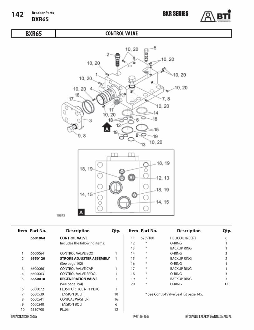
BXR SERIES
BREAKER TECHNOLOGY P/N 150-2086 HYDRAULIC BREAKER OWNER’S MANUAL
Breaker Parts142BXR65
Item Part No. Description Qty. Item Part No. Description Qty.
CONTROL VALVE
6601064 CONTROL VALVE Includes the following items:
1 6600064 CONTROL VALVE BOX 1 2 6550120 STROKE ADJUSTER ASSEMBLY 1 (See page 192) 3 6600066 CONTROL VALVE CAP 1 4 6600063 CONTROL VALVE SPOOL 1 5 6550018 REGENERATION VALVE 1 (See page 194) 6 6600072 FLUSH ORIFICE NPT PLUG 1 7 6600539 TENSION BOLT 10 8 6600541 CONICAL WASHER 16 9 6600540 TENSION BOLT 6 10 6550700 PLUG 12
11 6239180 HELICOIL INSERT 6 12 * O-RING 1 13 * BACKUP RING 1 14 * O-RING 2 15 * BACKUP RING 2 16 * O-RING 1 17 * BACKUP RING 1 18 * O-RING 3 19 * BACKUP RING 3 20 * O-RING 12
* See Control Valve Seal Kit page 145.
BXR65

BXR SERIES
HYDRAULIC BREAKER OWNER’S MANUAL P/N 150-2086 BREAKER TECHNOLOGY
Breaker Parts 143BXR65
Item Part No. Description Qty.
ACCUMULATOR ASSEMBLY
6600075 ACCUMULATOR ASSEMBLY Includes the following items:
1 6367557 ACCUMULATOR COVER 1 2 6600555 ACCUMULATOR BASE 1 3 6257070 GAS VALVE 1 4 6360045 DIAPHRAGM 1 5 6600164 ORIFICE ASSEMBLY 1 6 * O-RING 1 7 * BACKUP RING 1 8 6360137 BOLT 12
* See Accumulator Seal Kit page 147
BXR65
Item Part No. Description Qty.
12509
8
1
3
4
5
6
7
2
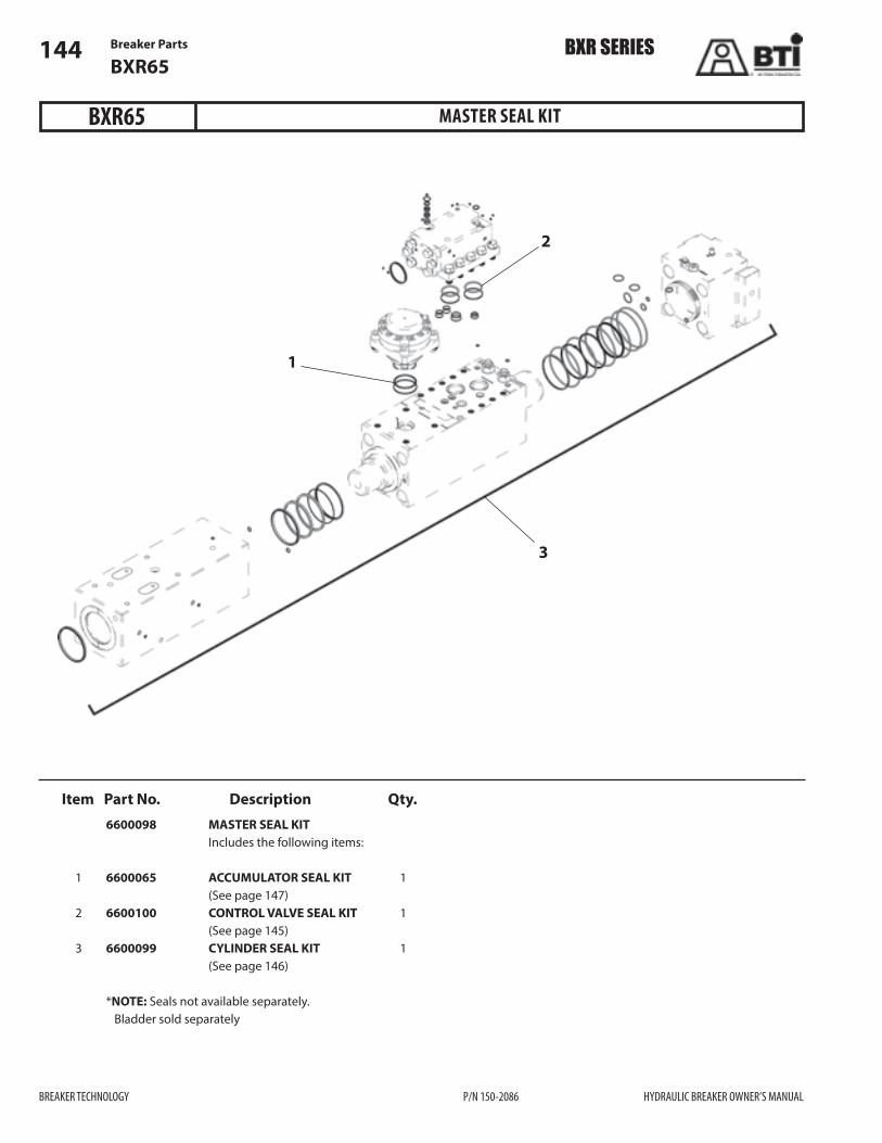
Breaker Parts144BXR65
Item Part No. Description Qty.
MASTER SEAL KIT
6600098 MASTER SEAL KIT Includes the following items:
1 6600065 ACCUMULATOR SEAL KIT 1 (See page 147) 2 6600100 CONTROL VALVE SEAL KIT 1 (See page 145) 3 6600099 CYLINDER SEAL KIT 1 (See page 146)
*NOTE: Seals not available separately. Bladder sold separately
BXR65
BXR SERIES
BREAKER TECHNOLOGY P/N 150-2086 HYDRAULIC BREAKER OWNER’S MANUAL
1
2
3

Breaker Parts 145BXR65
Item Part No. Description Qty. Item Part No. Description Qty.
CONTROL VALVE SEAL KIT
6600100 CONTROL VALVE SEAL KIT Includes the following items:
1 6550302 O-RING * 13 2 6550303 O-RING * 1 3 6550402 BACKUP RING * 1 4 6360088 O-RING * 2 5 6600400 BACKUP RING * 2 6 6360033 O-RING * 1 7 6360067 BACKUP RING * 1 8 6600500 O-RING * 3 9 6600501 BACKUP RING * 3 10 6131539 BACKUP RING * 1 11 6550309 O-RING * 3 12 6550407 BACKUP RING * 3
13 6501563 O-RING * 1
*NOTE: Items not available separately.
BXR SERIES
HYDRAULIC BREAKER OWNER’S MANUAL P/N 150-2086 BREAKER TECHNOLOGY
BXR65

Breaker Parts146BXR65
Item Part No. Description Qty. Item Part No. Description Qty.
BXR SERIES
BREAKER TECHNOLOGY P/N 150-2086 HYDRAULIC BREAKER OWNER’S MANUAL
Breaker Parts146BXR65
Item Part No. Description Qty.
INTERNAL SEAL KIT
6600099 CYLINDER SEAL KIT Includes the following items:
1 6130002 O-RING 1 2 6230046 O-RING 1 3 6250702 O-RING 2 4 6600181 QUAD RING 1 5 6600180 STEP SEAL 2 6 6600083 BUFFER SEAL 1 7 6250083OMS BUFFER SEAL 1 8 6250084 U-PACKING 1 9 6250086 DUST SEAL 1 10 6250033 O-RING 6 11 6500088 O-RING 5 12 6500007 O-RING 2
BXR65
13 6700007 O-RING 4 14 6131539 O-RING 1 15 6600200 DUST SEAL 1
*NOTE: Items not available separately.
15
7
8
9
10
5
4
6
13
11
3 2 1
11
14
1213
Orientation of the groove must be down.(Tool Side)

Breaker Parts 147BXR65
Item Part No. Description Qty.
ACCUMULATOR SEAL KIT
6600065 ACCUMULATOR SEAL KIT Includes the following items:
1 6230546 O-RING * 1 2 6230567 BACKUP RING * 1
*NOTE: Items not available separately.
BXR65
BXR SERIES
HYDRAULIC BREAKER OWNER’S MANUAL P/N 150-2086 BREAKER TECHNOLOGY

NOTES
148
BREAKER TECHNOLOGY P/N 150-2086 HYDRAULIC BREAKER OWNER’S MANUAL
BXR SERIES

Breaker Parts 149BXR85
Item Part No. Description Qty. Item Part No. Description Qty.
MAIN BREAKER ASSEMBLY
1 464-0030 BOX HOUSING WELDMENT 1 2 1912258 BOLT 18 3 1932059 NUT 18 4 1941039 TENSION WASHER 36 5 464-0045 SHIM PACK ASSEMBLY 8 6 464-0027 LOWER ACCESS COVER 1 7 464-0028 UPPER ACCESS COVER 1 8 1912491 BOLT 10 9 470-0026 RETAINER COVER 10 10 464-0021 SUPPORT PAD 8 11 464-0035 LOWER ISOLATOR ASS’Y 1 12 481-0027 SIDE EAR ISOLATOR 2 13 464-0036 UPPER ISOLATOR 1 14 481-0041 MOLDED CAP 2 15 474-0039 INSPECTION HOLE PLUG 2
16 BXR85B BARE BREAKER 1 (See page 151)
500-1161 BXR85 DECAL KIT 1
NOTE: For mounting bracket and hardware, contact your BTI representative.
BXR85
BXR SERIES
HYDRAULIC BREAKER OWNER’S MANUAL P/N 150-2086 BREAKER TECHNOLOGY

Breaker Parts150BXR85
BARE BREAKERBXR85
BXR SERIES
BREAKER TECHNOLOGY P/N 150-2086 HYDRAULIC BREAKER OWNER’S MANUAL

Breaker Parts 151BXR85
Item Part No. Description Qty. Item Part No. Description Qty.
BARE BREAKER
BXR85 BARE BREAKER Includes items 1–49
1 6850051 CYLINDER 1 2 6850083 BUFFER SEAL * 1 3 6850084 U-PACKING * 2 4 6850086 DUST SEAL * 1 5 6850053 PISTON 1 6 6850060 PACKING BUSHING 1 7 6850085 STEP SEAL * 2 8 6857083 BUFFER SEAL * 1 9 6850082 GAS SEAL, QUAD RING * 1 10 6850134 O-RING * 6 11 6850052 REAR HEAD 1 12 6850054 FRONT HEAD 1 13 6850061 TIE ROD C/W ISOLATOR 4 14 6850011 CENTRALIZER WASHER 4 15 6850019 NORDLOCK WASHER 4 16 6850013 TIE ROD NUT 4 17 6850525 HELICOIL INSERT 4 18 6601064 CONTROL VALVE 1 (See page 152) 19 6600014 DOWEL PIN 2 20 6701539 PLUG 4 21 6700007 O-RING * 4 23 6250702 O-RING * 2 24 6850094 ADAPTER 2 25 6131539 O-RING * 1 26 6130002 O-RING * 1 27 6360046 O-RING * 1 28 6361561 PORT PLUG 1 29 6257139 PORT PLUG 1 30 6850055 FRONT BUSHING 1 31 6850006 REAR BUSHING 1 32 6850009 KEEPER PIN 5 33 6550507 STOPPER PLUG 5 34 6850039 RETAINING PIN 2 35 6551529 GREASE ZERK 2 36 6557527 AIR VALVE ASSEMBLY 1 (See page 193) 37 BXR85-B-1350 BLUNT TOOL REF 37 BXR85-M-1350 MOIL TOOL REF 37 BXR85-C-1350 CHISEL TOOL REF 38 6600075 ACCUMULATOR ASSEMBLY 1 (See page 143) 39 6257070 GAS VALVE 1 40 6550005 GREASE ZERK ADAPTER 1 41 6150024 PLUG 1 42 6500088 O-RING * 5 43 6850200 DUST SEAL * 1 44 6550526 HELICOIL INSERT 4
45 6550541 CONICAL WASHER 4 46 6360037 BOLT 4 47 6239180 HELICOIL INSERT 10 48 6700027 PLUG 2 49 6500007 O-RING * 2
6850098 MASTER SEAL KIT REF Includes: 6600065, 6600100, & 6850099 (See page 154)
6600065 ACCUMULATOR SEAL KIT REF (See page 159)
6600100 CONTROL VALVE SEAL KIT REF (See page 156 )
6850099 INTERNAL SEAL KIT REF (See page 157)
*NOTE: Seals not available separately.
BXR85
BXR SERIES
HYDRAULIC BREAKER OWNER’S MANUAL P/N 150-2086 BREAKER TECHNOLOGY

6851064 CONTROL VALVE Includes the following items:
1 6600064 CONTROL VALVE BOX 1 2 6550120 STROKE ADJUSTER ASSEMBLY 1 (See page 192) 3 6600066 CONTROL VALVE CAP 1 4 6600063 CONTROL VALVE SPOOL 1 5 6550018 REGENERATION VALVE 1 (See page 194) 6 6850072 FLUSH ORIFICE NPT PLUG 1 7 6600539 TENSION BOLT 10 8 6600541 CONICAL WASHER 16 9 6600540 TENSION BOLT 6 10 6550700 PLUG 12
11 6230180 HELICOIL INSERT 6 12 * O-RING 1 13 * BACKUP RING 1 14 * O-RING 2 15 * BACKUP RING 2 16 * O-RING 1 17 * BACKUP RING 1 18 * O-RING 3 19 * BACKUP RING 3 20 * O-RING 12
* See Control Valve Seal Kit, page 156.
Breaker Parts152BXR85
Item Part No. Description Qty. Item Part No. Description Qty.
CONTROL VALVEBXR85
BXR SERIES
BREAKER TECHNOLOGY P/N 150-2086 HYDRAULIC BREAKER OWNER’S MANUAL

Breaker Parts 153BXR85
Item Part No. Description Qty. Item Part No. Description Qty.
ACCUMULATOR ASSEMBLY
6600075 ACCUMULATOR ASSEMBLY Includes the following items:
1 6367557 ACCUMULATOR COVER 1 2 6600555 ACCUMULATOR BASE 1 3 6257070 GAS VALVE 1 4 6360045 DIAPHRAGM 1 5 6600164 ORIFICE ASSEMBLY 1 6 * O-RING 1 7 * BACKUP RING 1 8 6360137 BOLT 12
* Refer to Accumulator Seal Kit, page 159
BXR85
BXR SERIES
HYDRAULIC BREAKER OWNER’S MANUAL P/N 150-2086 BREAKER TECHNOLOGY
12509
8
1
3
4
5
6
7
2

Breaker Parts154BXR85
Item Part No. Description Qty.
MASTER SEAL KIT
6850098 MASTER SEAL KIT Includes the following items:
1 6600065 ACCUMULATOR SEAL KIT 1 (See page 159) 2 6600100 CONTROL VALVE SEAL KIT 1 (See page 156) 3 6850099 INTERNAL SEAL KIT 1 (See page 157)
* NOTE: Seals not available separately. Bladder sold separately
BXR85
BXR SERIES
BREAKER TECHNOLOGY P/N 150-2086 HYDRAULIC BREAKER OWNER’S MANUAL
1
2
3
A#ects All Serial NumbersExcept 50 & 51

Breaker Parts 155BXR85
Item Part No. Description Qty.
MASTER SEAL KIT
6850098PT MASTER SEAL KIT Includes the following items:
1 6600065 ACCUMULATOR SEAL KIT 1 (See page 159) 2 6600100 CONTROL VALVE SEAL KIT 1 (See page 156) 3 6850099PT INTERNAL SEAL KIT 1
* NOTE: Seals not available separately. Bladder sold separately
BXR85
BXR SERIES
HYDRAULIC BREAKER OWNER’S MANUAL P/N 150-2086 BREAKER TECHNOLOGY
1
2
3
A#ects Serial Numbers 50 & 51 only

13 6501563 O-RING * 1
*NOTE: Items not available separately.
Breaker Parts156BXR85
BXR SERIES
BREAKER TECHNOLOGY P/N 150-2086 HYDRAULIC BREAKER OWNER’S MANUAL
Item Part No. Description Qty. Item Part No. Description Qty.
CONTROL VALVE SEAL KITBXR85
6600100 CONTROL VALVE SEAL KIT Includes the following items:
1 6550302 O-RING * 13 2 6550303 O-RING * 1 3 6550402 BACKUP RING * 1 4 6360088 O-RING * 2 5 6600400 BACKUP RING * 2 6 6360033 O-RING * 1 7 6360067 BACKUP RING * 1 8 6600500 O-RING * 3 9 6600501 BACKUP RING * 3 10 6131539 BACKUP RING * 1 11 6550309 O-RING * 3 12 6550407 BACKUP RING * 3

Breaker Parts 157BXR85
Item Part No. Description Qty.
INTERNAL SEAL KIT
6850099 INTERNAL SEAL KIT Includes the following items:
1 6130002 O-RING 1 2 6360046 O-RING 1 3 6250702 O-RING 2 4 6850082 QUAD RING 1 5 6850085 STEP SEAL 2 6 6850083OMS BUFFER SEAL 1 7 6850084OMS BUFFER SEAL 1 8 6850084 U-PACKING 1 9 6850086 DUST SEAL 1 10 6850134 O-RING 6 11 6500088 O-RING 5 12 6500007 O-RING 2
BXR85
BXR SERIES
HYDRAULIC BREAKER OWNER’S MANUAL P/N 150-2086 BREAKER TECHNOLOGY
Item Part No. Description Qty. 13 6700007 O-RING 4 14 6131539 O-RING 1 15 6850200 DUST SEAL 1 16 6857083 BUFFER SEAL 1 NOTE: Items not available separately.
A#ects All Serial NumbersExcept 50 & 51 6
8
9
10
5
4
16
13
11
122 1
11
14
313
Orientation of the groove must be down.(Tool Side)
7
15
A#ects All Serial NumbersExcept 50 & 51

Breaker Parts158BXR85
Item Part No. Description Qty. Item Part No. Description Qty. 6850099PT INTERNAL SEAL KIT Includes the following items:
1 6130002 O-RING 1 2 6360046 O-RING 1 3 6250702 O-RING 2 4 6850082 QUAD RING 1 5 6850085 STEP SEAL 2 6 6857083 BUFFER SEAL 1 7 6850083 BUFFER SEAL 1 8 6850084PT U-PACKING 2 9 6850086 DUST SEAL 1 10 6850134 O-RING 6 11 6500088 O-RING 5 12 6500007 O-RING 2
13 6700007 O-RING 4 14 6131539 O-RING 1 15 6850200 DUST SEAL 1 NOTE: Items not available separately
BXR SERIES
BREAKER TECHNOLOGY P/N 150-2086 HYDRAULIC BREAKER OWNER’S MANUAL
14
A#ects Serial Numbers 50 & 51 only
INTERNAL SEAL KITBXR85
A#ects All Serial NumbersExcept 50 & 51 7
8
9
10
5
4
6
13
11
122 1
11
313
Orientation of the groove must be down.(Tool Side)
8
15

Breaker Parts 159BXR85
BXR SERIES
HYDRAULIC BREAKER OWNER’S MANUAL P/N 150-2086 BREAKER TECHNOLOGY
6600065 ACCUMULATOR SEAL KIT Includes the following items:
1 6230546 O-RING 1 2 6230567 BACKUP RING 1
NOTE: Items not available separately.
Item Part No. Description Qty.
ACCUMULATOR SEAL KITBXR85

NOTES
160
BREAKER TECHNOLOGY P/N 150-2086 HYDRAULIC BREAKER OWNER’S MANUAL
BXR SERIES
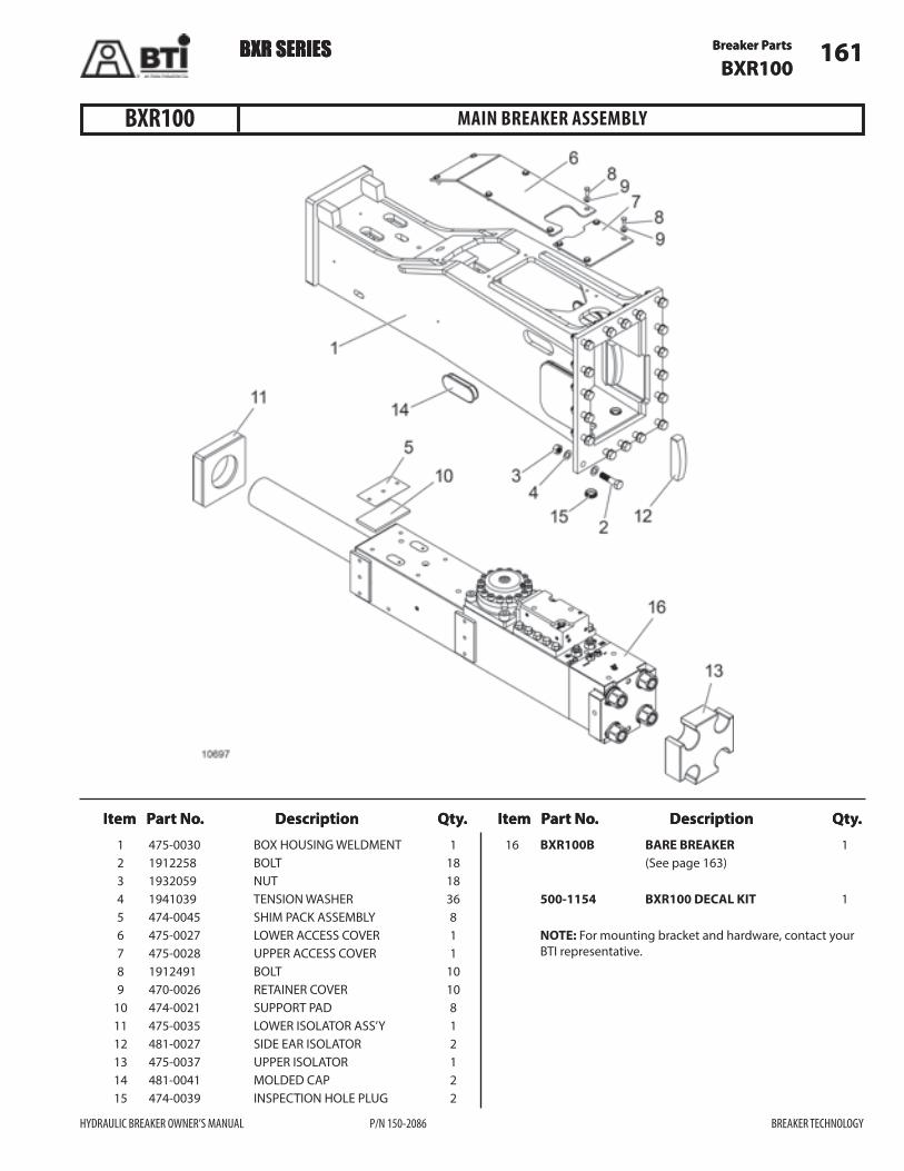
Breaker Parts 161BXR100
Item Part No. Description Qty. Item Part No. Description Qty.
BXR SERIES
HYDRAULIC BREAKER OWNER’S MANUAL P/N 150-2086 BREAKER TECHNOLOGY
Breaker Parts 161BXR100
Item Part No. Description Qty. Item Part No. Description Qty.
MAIN BREAKER ASSEMBLY
1 475-0030 BOX HOUSING WELDMENT 1 2 1912258 BOLT 18 3 1932059 NUT 18 4 1941039 TENSION WASHER 36 5 474-0045 SHIM PACK ASSEMBLY 8 6 475-0027 LOWER ACCESS COVER 1 7 475-0028 UPPER ACCESS COVER 1 8 1912491 BOLT 10 9 470-0026 RETAINER COVER 10 10 474-0021 SUPPORT PAD 8 11 475-0035 LOWER ISOLATOR ASS’Y 1 12 481-0027 SIDE EAR ISOLATOR 2 13 475-0037 UPPER ISOLATOR 1 14 481-0041 MOLDED CAP 2 15 474-0039 INSPECTION HOLE PLUG 2
16 BXR100B BARE BREAKER 1 (See page 163)
500-1154 BXR100 DECAL KIT 1
NOTE: For mounting bracket and hardware, contact your BTI representative.
BXR100
BXR SERIES

Breaker Parts162BXR100
BARE BREAKER BXR100
BXR SERIES
BREAKER TECHNOLOGY P/N 150-2086 HYDRAULIC BREAKER OWNER’S MANUAL

Breaker Parts 163BXR100
Item Part No. Description Qty. Item Part No. Description Qty.
BARE BREAKER
BXR100B BARE BREAKER 1 Includes items 1–49
1 6100051 CYLINDER 1 2 6050083 BUFFER SEAL * 1 3 6050084 U-PACKING * 2 4 6050086 DUST SEAL * 1 5 6100053 PISTON 1 6 6100060 PACKING BUSHING 1 7 6100085 STEP SEAL * 2 8 6107083 BUFFER SEAL * 1 9 6100082 GAS SEAL, QUAD RING * 1 10 6050134 O-RING * 6 11 6100052 REAR HEAD 1 12 6100054 FRONT HEAD 1 13 6100061 TIE ROD C/W ISOLATOR 4 14 6400011 CENTRALIZER WASHER 4 15 6400019 NORDLOCK WASHER 4 16 6400013 TIE ROD NUT 4 17 6400525 HELICOIL INSERT 4 18 6101064 CONTROL VALVE 1 (See page 164) 19 6600014 DOWEL PIN 2 20 6701539 PLUG 4 21 6700007 O-RING * 4 23 6550307 O-RING * 2 24 6550094 ADAPTER 2 25 6131539 O-RING * 2 27 6360046 O-RING * 1 28 6361561 PORT PLUG 1 29 6050024 PORT PLUG 1 30 6100055 FRONT BUSHING 1 31 6100006 REAR BUSHING 1 32 6100009 KEEPER PIN 5 33 6550507 STOPPER PLUG 5 34 6100039 RETAINING PIN 2 35 6551529 GREASE ZERK 2 36 6557527 AIR VALVE ASSEMBLY 1 (See page 193) 37 BXR100-B-1450 BLUNT TOOL REF 37 BXR100-M-1450 MOIL TOOL REF 37 BXR100-C-1450 CHISEL TOOL REF 38 6600075 ACCUMULATOR ASSEMBLY 1 (See page 165) 39 6257070 GAS VALVE 1 40 6550005 GREASE ZERK ADAPTER 1 41 6150024 PLUG 1 42 6500088 O-RING * 5 43 6100200 DUST SEAL * 1 44 6550526 HELICOIL INSERT 4 45 6550541 CONICAL WASHER 4 46 6360037 BOLT 4
47 6100526 HELICOIL INSERT 10 48 6700027 PLUG 2 49 6500007 O-RING * 2
6100098 MASTER SEAL KIT REF Includes 6600065, 6400100, & 6100099 (See page 166)
6600065 ACCUMULATOR SEAL KIT REF (See page 171)
6400100 CONTROL VALVE SEAL KIT REF (See page 168)
6100099 INTERNAL SEAL KIT REF (See page 169)
* NOTE: Seals not available separately
BXR100
BXR SERIES
HYDRAULIC BREAKER OWNER’S MANUAL P/N 150-2086 BREAKER TECHNOLOGY

Breaker Parts164BXR100
Item Part No. Description Qty. Item Part No. Description Qty.
CONTROL VALVE
6101064 CONTROL VALVE Includes the following items:
1 6400064 CONTROL VALVE BOX 1 2 6550120 STROKE ADJUSTER ASSEMBLY 1 (See page 192) 3 6400066 CONTROL VALVE CAP 1 4 6400063 CONTROL VALVE SPOOL 1 5 6550018 REGENERATION VALVE 1 (See page 194) 6 6550072 FLUSH ORIFICE NPT PLUG 1 7 6100558 TENSION BOLT 10 8 6550541 CONICAL WASHER 6 9 6550539 TENSION BOLT 6 10 6550700 PLUG 12
11 6550526 HELICOIL INSERT 6 12 * O-RING 1 13 * BACKUP RING 1 14 * O-RING 2 15 * BACKUP RING 2 16 * O-RING 1 17 * BACKUP RING 1 18 * O-RING 3 19 * BACKUP RING 3 20 * O-RING 12
* See Control Valve Seal Kit page 168
BXR100
BXR SERIES
BREAKER TECHNOLOGY P/N 150-2086 HYDRAULIC BREAKER OWNER’S MANUAL

Breaker Parts 165BXR100
Item Part No. Description Qty.
ACCUMULATOR ASSEMBLY
6600075 ACCUMULATOR ASSEMBLY Includes the following items:
1 6367557 ACCUMULATOR COVER 1 2 6600555 ACCUMULATOR BASE 1 3 6257070 GAS VALVE 1 4 6360045 DIAPHRAGM 1 5 6600164 ORIFICE ASSEMBLY 1 6 * O-RING 1 7 * BACKUP RING 1 8 6360137 BOLT 12
* Refer to Accumulator Seal Kit page 171
BXR100
BXR SERIES
HYDRAULIC BREAKER OWNER’S MANUAL P/N 150-2086 BREAKER TECHNOLOGY
12509
8
1
3
4
5
6
7
2

Breaker Parts166BXR100
Item Part No. Description Qty.
MASTER SEAL KIT
6100098 MASTER SEAL KIT Includes the following items:
1 6600065 ACCUMULATOR SEAL KIT 1 (See page 171) 2 6400100 CONTROL VALVE SEAL KIT 1 (See page 168) 3 6100099 INTERNAL SEAL KIT 1 (See page 169)
* NOTE: Seals not available separately Bladder sold separately
BXR100
BXR SERIES
BREAKER TECHNOLOGY P/N 150-2086 HYDRAULIC BREAKER OWNER’S MANUAL
1
2
3
A#ects All Serial NumbersExcept 50 & 51

Breaker Parts 167BXR100
MASTER SEAL KITBXR100
BXR SERIES
HYDRAULIC BREAKER OWNER’S MANUAL P/N 150-2086 BREAKER TECHNOLOGY
Item Part No. Description Qty. 6100098PT MASTER SEAL KIT Includes the following items:
1 6600065 ACCUMULATOR SEAL KIT 1 (See page 171) 2 6400100 CONTROL VALVE SEAL KIT 1 (See page 156) 3 6100099PT INTERNAL SEAL KIT 1
* NOTE: Seals not available separately. Bladder sold separately
1
2
3
A#ects Serial Numbers 50 & 51 only

Breaker Parts168BXR100
BXR SERIES
BREAKER TECHNOLOGY P/N 150-2086 HYDRAULIC BREAKER OWNER’S MANUAL
Item Part No. Description Qty. Item Part No. Description Qty.
CONTROL VALVE SEAL KIT
6400100 CONTROL VALVE SEAL KIT Includes the following items:
1 6550302 O-RING * 13 2 6550303 O-RING * 1 3 6550402 BACKUP RING * 1 4 6550304 O-RING * 2 5 6550403 BACKUP RING * 2 6 6230546 O-RING * 1 7 6550404 BACKUP RING * 1 8 6130002 O-RING * 3 9 6550405 BACKUP RING * 3 10 6131539 BACKUP RING * 1 11 6550309 O-RING * 3 12 6550407 BACKUP RING * 3
13 6501563 O-RING * 1
* NOTE: Items not available separately
BXR100

Breaker Parts 169BXR100
Item Part No. Description Qty.
INTERNAL SEAL KITBXR100
BXR SERIES
HYDRAULIC BREAKER OWNER’S MANUAL P/N 150-2086 BREAKER TECHNOLOGY
Item Part No. Description Qty.
14A#ects All Serial NumbersExcept 50 & 51 6
8
9
10
5
4
16
13
11
122 1
11
313
Orientation of the groove must be down.(Tool Side)
7
15
6400099 INTERNAL SEAL KIT Includes the following items:
1 6360046 O-RING 1 2 6550308 O-RING 1 3 6550307 O-RING 2 4 6550082 QUAD RING 1 5 6550085 STEP SEAL 2 6 6550083OMS BUFFER SEAL 1 7 6550084OMS BUFFER SEAL 1 8 6550084 U-PACKING 1 9 6550086 DUST SEAL 1 10 6551134 O-RING 6
11 6500088 O-RING 5 12 6500007 O-RING 2 13 6700007 O-RING 4 14 6131539 O-RING 1 15 6100200 DUST SEAL 1 16 6107083 BUFFER SEAL 1
NOTE: Items not available separately
A#ects All Serial NumbersExcept 50 & 51

Breaker Parts170BXR100
Item Part No. Description Qty. Item Part No. Description Qty. 6100099PT INTERNAL SEAL KIT Includes the following items:
1 6360046 O-RING 1 3 6550307 O-RING 2 4 6100082 QUAD RING 1 5 6100085 STEP SEAL 3 6 6107083 BUFFER SEAL 1 7 6050083 BUFFER SEAL 1 8 6050084PT U-PACKING 2 9 6050086 DUST SEAL 1 10 6050134 O-RING 6 11 6500088 O-RING 5 12 6500007 O-RING 2 13 6700007 O-RING 4
BXR SERIES
BREAKER TECHNOLOGY P/N 150-2086 HYDRAULIC BREAKER OWNER’S MANUAL
7
8
9
10
5
4
6
13
11
122 1
11
14
313
Orientation of the groove must be down.(Tool Side)
8
15
INTERNAL SEAL KITBXR100
14 6131539 O-RING 2 15 6850087 OIL SEAL 1 16 6100200 DUST SEAL 1 NOTE: Items not available separately
A#ects Serial Numbers 50 & 51 only

Breaker Parts 171BXR100
BXR SERIES
HYDRAULIC BREAKER OWNER’S MANUAL P/N 150-2086 BREAKER TECHNOLOGY
Item Part No. Description Qty.
ACCUMULATOR SEAL KITBXR100
6600065 ACCUMULATOR SEAL KIT Includes the following items:
1 6230546 O-RING 1 2 6230567 BACKUP RING 1
NOTE: Items not available separately.

NOTES
172
BREAKER TECHNOLOGY P/N 150-2086 HYDRAULIC BREAKER OWNER’S MANUAL
BXR SERIES172
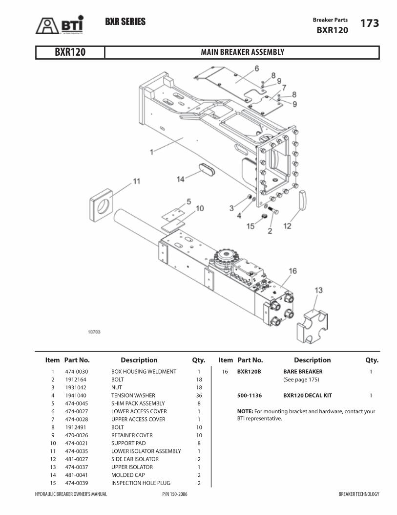
Breaker Parts 173BXR120
Item Part No. Description Qty. Item Part No. Description Qty.
MAIN BREAKER ASSEMBLY
1 474-0030 BOX HOUSING WELDMENT 1 2 1912164 BOLT 18 3 1931042 NUT 18 4 1941040 TENSION WASHER 36 5 474-0045 SHIM PACK ASSEMBLY 8 6 474-0027 LOWER ACCESS COVER 1 7 474-0028 UPPER ACCESS COVER 1 8 1912491 BOLT 10 9 470-0026 RETAINER COVER 10 10 474-0021 SUPPORT PAD 8 11 474-0035 LOWER ISOLATOR ASSEMBLY 1 12 481-0027 SIDE EAR ISOLATOR 2 13 474-0037 UPPER ISOLATOR 1 14 481-0041 MOLDED CAP 2 15 474-0039 INSPECTION HOLE PLUG 2
16 BXR120B BARE BREAKER 1 (See page 175)
500-1136 BXR120 DECAL KIT 1
NOTE: For mounting bracket and hardware, contact your BTI representative.
BXR120
BXR SERIES
HYDRAULIC BREAKER OWNER’S MANUAL P/N 150-2086 BREAKER TECHNOLOGY

Breaker Parts174BXR120
BARE BREAKERBXR120
BXR SERIES
BREAKER TECHNOLOGY P/N 150-2086 HYDRAULIC BREAKER OWNER’S MANUAL

Breaker Parts 175BXR120
Item Part No. Description Qty. Item Part No. Description Qty.
BARE BREAKER
BXR120B BARE BREAKER Includes items 1–49
1 6400051 CYLINDER 1 2 6400083 BUFFER SEAL * 1 3 6400084 U-PACKING * 2 4 6400086 DUST SEAL * 1 5 6400053 PISTON 1 6 6400060 PACKING BUSHING 1 7 6400085 STEP SEAL * 2 8 6407083 BUFFER SEAL * 1 9 6400082 GAS SEAL, QUAD RING * 1 10 6400134 O-RING * 6 11 6400052 REAR HEAD 1 12 6400054 FRONT HEAD 1 13 6400061 TIE ROD C/W ISOLATOR 4 14 6400011 CENTRALIZER WASHER 4 15 6400019 NORDLOCK WASHER 4 16 6400013 TIE ROD NUT 4 17 6400525 HELICOIL INSERT 4 18 6401064 CONTROL VALVE 1 (See page 176) 19 6550014 DOWEL PIN 2 20 6701539 PLUG 4 21 6700007 O-RING * 4 23 6550307 O-RING * 2 24 6550094 ADAPTER 2 25 6131539 O-RING * 1 26 6360046 O-RING * 1 27 6550308 O-RING * 1 28 6550561 PORT PLUG 1 29 6361561 PORT PLUG 1 30 6400055 FRONT BUSHING 1 31 6400006 REAR BUSHING 1 32 6400009 KEEPER PIN 5 33 6550507 STOPPER PLUG 5 34 6400039 RETAINING PIN 2 35 6551529 GREASE ZERK 2 36 6557527 AIR VALVE ASSEMBLY 1 (See page 193) 37 BXR120-B-1500 BLUNT TOOL REF 37 BXR120-M-1500 MOIL TOOL REF 37 BXR120-C-1500 CHISEL TOOL REF 38 6550075 ACCUMULATOR ASSEMBLY 1 (See page 177) 39 6257070 GAS VALVE 1 40 6550005 GREASE ZERK ADAPTER 1 41 6150024 PLUG 1 42 6500088 O-RING * 5 43 6400200 DUST SEAL * 1 44 6400527 HELICOIL INSERT 4
45 6550543 CONICAL WASHER 4 46 6400599 BOLT 4 47 6550526 HELICOIL INSERT 10 48 6700027 PLUG 2 49 6500007 O-RING * 2
6400098 MASTER SEAL KIT REF Includes 6550065, 6400100, & 6400099 (See page 178) 6550065 ACCUMULATOR SEAL KIT REF (See page 181)
6400100 CONTROL VALVE SEAL KIT REF (See page 179)
6400099 INTERNAL SEAL KIT REF (See page 180)
* NOTE: Seals not available separately
BXR120
BXR SERIES
HYDRAULIC BREAKER OWNER’S MANUAL P/N 150-2086 BREAKER TECHNOLOGY

Breaker Parts176BXR120
Item Part No. Description Qty. Item Part No. Description Qty.
CONTROL VALVE
6401064 CONTROL VALVE Includes the following items:
1 6400064 CONTROL VALVE BOX 1 2 6550120 STROKE ADJUSTER ASSEMBLY 1 (See page 192) 3 6400066 CONTROL VALVE CAP 1 4 6400063 CONTROL VALVE SPOOL 1 5 6550018 REGENERATION VALVE 1 (See page 194) 6 6400072 FLUSH ORIFICE NPT PLUG 1 7 6400540 TENSION BOLT 10 8 6550541 CONICAL WASHER 6 9 6550539 TENSION BOLT 6 10 6550700 PLUG 12
11 6550526 HELICOIL INSERT 6 12 * O-RING 1 13 * BACKUP RING 1 14 * O-RING 2 15 * BACKUP RING 2 16 * O-RING 1 17 * BACKUP RING 1 18 * O-RING 3 19 * BACKUP RING 3 20 * O-RING 8
* See Control Valve Seal Kit, page 179
BXR120
BXR SERIES
BREAKER TECHNOLOGY P/N 150-2086 HYDRAULIC BREAKER OWNER’S MANUAL

12510
Breaker Parts 177BXR120
Item Part No. Description Qty.
ACCUMULATOR ASSEMBLY
6550075 ACCUMULATOR ASSEMBLY Includes the following items:
1 6550556 ACCUMULATOR COVER 1 2 6550555 ACCUMULATOR BASE 1 3 6257070 GAS VALVE 1 4 6550045 DIAPHRAGM 1 5 6550164 ORIFICE ASSEMBLY 1 6 * O-RING 1 7 * BACKUP RING 1 8 6230540 BOLT 16
* See Accumulator Seal Kit, page 181
BXR120
BXR SERIES
HYDRAULIC BREAKER OWNER’S MANUAL P/N 150-2086 BREAKER TECHNOLOGY
8
1
3
4
5
6
7
2

Breaker Parts178BXR120
Item Part No. Description Qty. Item Part No. Description Qty.
MASTER SEAL KIT
6400098 MASTER SEAL KIT Includes the following: 1 6550065 ACCUMULATOR SEAL KIT 1 (See page 181) 2 6400100 CONTROL VALVE SEAL KIT 1 (See page 179) 3 6400099 INTERNAL SEAL KIT 1 (See page 180)
* NOTE: Seals not available separately
BXR120
BXR SERIES
BREAKER TECHNOLOGY P/N 150-2086 HYDRAULIC BREAKER OWNER’S MANUAL
1
2
3
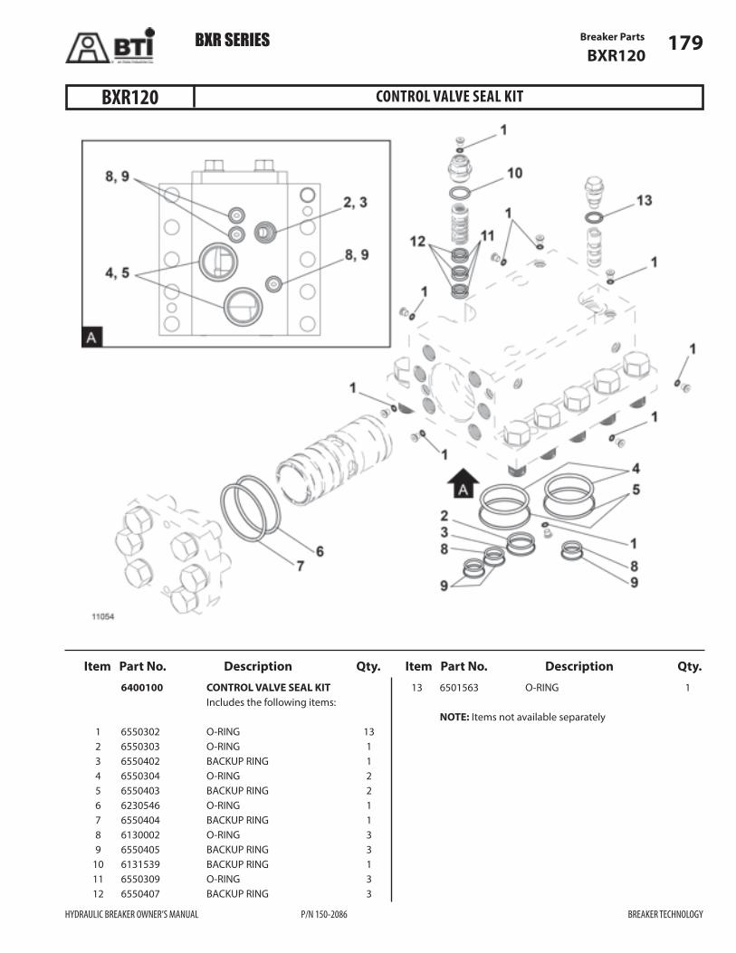
Breaker Parts 179BXR120
Item Part No. Description Qty. Item Part No. Description Qty.
CONTROL VALVE SEAL KIT
6400100 CONTROL VALVE SEAL KIT Includes the following items:
1 6550302 O-RING 13 2 6550303 O-RING 1 3 6550402 BACKUP RING 1 4 6550304 O-RING 2 5 6550403 BACKUP RING 2 6 6230546 O-RING 1 7 6550404 BACKUP RING 1 8 6130002 O-RING 3 9 6550405 BACKUP RING 3 10 6131539 BACKUP RING 1 11 6550309 O-RING 3 12 6550407 BACKUP RING 3
13 6501563 O-RING 1
NOTE: Items not available separately
BXR120
BXR SERIES
HYDRAULIC BREAKER OWNER’S MANUAL P/N 150-2086 BREAKER TECHNOLOGY

Breaker Parts180BXR120
BXR SERIES
BREAKER TECHNOLOGY P/N 150-2086 HYDRAULIC BREAKER OWNER’S MANUAL
INTERNAL SEAL KITBXR120
Item Part No. Description Qty. 6400099 INTERNAL SEAL KIT Includes the following items:
1 6360046 O-RING 1 2 6550308 O-RING 1 3 6550307 O-RING 2 4 6400082 QUAD RING 1 5 6400085 STEP SEAL 2 6 6400083OMS BUFFER SEAL 1 7 6400084OMS BUFFER SEAL 1 8 6400084 U-PACKING 1 9 6400086 DUST SEAL 1 10 6400134 O-RING 6
11 6500088 O-RING 5 12 6500007 O-RING 2 13 6700007 O-RING 4 14 6131539 O-RING 1 15 6400200 DUST SEAL 1 16 6107083 BUFFER SEAL 1
NOTE: Items not available separately
14
15
6
8
9
10
5
4
16
13
11
122 1
11
313
Orientation of the groove must be down.(Tool Side)
7
*

Breaker Parts 181BXR120
Item Part No. Description Qty.
ACCUMULATOR SEAL KIT
6550065 ACCUMULATOR SEAL KIT Includes the following items:
1 6550300 O-RING 1 2 6550400 BACKUP RING 1
NOTE: Items not available separately
BXR120
BXR SERIES
HYDRAULIC BREAKER OWNER’S MANUAL P/N 150-2086 BREAKER TECHNOLOGY

NOTES
182
BREAKER TECHNOLOGY P/N 150-2086 HYDRAULIC BREAKER OWNER’S MANUAL
BXR SERIES

Breaker Parts 183BXR160
Item Part No. Description Qty. Item Part No. Description Qty.
MAIN BREAKER ASSEMBLY
1 481-0030 BOX HOUSING WELDMENT 1 2 1912258 BOLT 16 3 1931059 NUT 16 4 1941039 TENSION WASHER 32 5 481-0045 LAMINATED SHIM 8 6 481-0025 UPPER ACCESS COVER 1 7 481-0033 UPPER COVER 1 8 1912244 BOLT 10 9 470-0026 RETAINER COVER 10 10 481-0021 SUPPORT PAD 8 11 481-0035 LOWER ISOLATOR ASSEMBLY 1 12 481-0027 SIDE EAR ISOLATOR 2 13 481-0026 UPPER ISOLATOR 1 14 481-0041 MOLDED CAP 2 15 474-0039 INSPECTION HOLE PLUG 2
16 BXR160B BARE BREAKER See page page 185.
500-1111 BXR160 DECAL KIT 1 NOTE: For mounting bracket and hardware, contact your BTI representative.
BXR160
BXR SERIES
HYDRAULIC BREAKER OWNER’S MANUAL P/N 150-2086 BREAKER TECHNOLOGY

Breaker Parts184BXR160
BARE BREAKERBXR160
BXR SERIES
BREAKER TECHNOLOGY P/N 150-2086 HYDRAULIC BREAKER OWNER’S MANUAL

Breaker Parts 185BXR160
Item Part No. Description Qty. Item Part No. Description Qty.
BARE BREAKER
BXR160B BARE BREAKER Includes items 1–49
1 6550051 CYLINDER 1 2 6550083 BUFFER SEAL * 1 3 6550084 U-PACKING * 2 4 6550086 DUST SEAL * 1 5 6550053 PISTON 1 6 6550060 PACKING BUSHING 1 7 6550085 STEP SEAL * 2 8 6551083 BUFFER SEAL * 1 9 6550082 QUAD RING GAS SEAL * 1 10 6551134 O-RING * 6 11 6550052 REAR HEAD 1 12 6550054 FRONT HEAD 1 13 6550061 TIE ROD C/W ISOLATOR 4 14 6550011 CENTRALIZER WASHER 4 15 6550019 NORDLOCK WASHER 4 16 6550013 TIE ROD NUT 4 17 6550525 HELICOIL INSERT 4 18 6551064 CONTROL VALVE 1 (See page 186) 19 6550014 DOWEL PIN 2 20 6701539 PLUG 4 21 6700007 O-RING * 4 23 6550307 O-RING * 2 24 6550094 ADAPTER 2 25 6131539 O-RING * 1 26 6360046 O-RING * 1 27 6550308 O-RING * 1 28 6550561 PORT PLUG 1 29 6361561 PORT PLUG 1 30 6550055 FRONT BUSHING 1 31 6550006 REAR BUSHING 1 32 6550009 KEEPER PIN 5 33 6550507 STOPPER PLUG 5 34 6550039 RETAINING PIN 2 35 6551529 GREASE ZERK 2 36 6557527 AIR VALVE ASSEMBLY 1 (See page 193) 37 BXR160-B-1700 BLUNT TOOL REF 37 BXR160-M-1700 MOIL TOOL REF 37 BXR160-C-1700 CHISEL TOOL REF 38 6257070 GAS VALVE 1 39 6550005 GREASE ZERK ADAPTER 1 40 6150024 PLUG 1 41 6500088 O-RING * 5 42 6550528 HELICOIL INSERT 10 43 6550075 ACCUMULATOR ASSEMBLY 1 (See page 187) 44 6550543 CONICAL WASHER 4 45 6550599 BOLT 4
46 6400526 HELICOIL INSERT 4 47 6550200 DUST SEAL 1 48 6700027 PLUG 2 49 6500007 O-RING * 2
6550098 MASTER SEAL KIT REF Includes 6550065, 6550100, & 6400099 (See page 188)
6550065 ACCUMULATOR SEAL KIT REF (See page 191)
6550100 CONTROL VALVE SEAL KIT REF (See page 189)
6550099 INTERNAL SEAL KIT REF (See page 190)
* NOTE: Seals not available separately
BXR160
BXR SERIES
HYDRAULIC BREAKER OWNER’S MANUAL P/N 150-2086 BREAKER TECHNOLOGY

Breaker Parts186BXR160
Item Part No. Description Qty. Item Part No. Description Qty.
CONTROL VALVE
6551064 CONTROL VALVE Includes the following items:
1 6550064 CONTROL VALVE BOX 1 2 6550120 STROKE ADJUSTER ASSY 1 (See page 192) 3 6550066 CONTROL VALVE CAP 1 4 6550063 CONTROL VALVE 1 5 6550018 REGENERATION VALVE 1 (See page 194) 6 6550072 FLUSH ORIFICE NPT PLUG 1 7 6550558 TENSION BOLT 10 8 6550540 CONICAL WASHER 10 9 6550539 TENSION BOLT 6 10 6550541 CONICAL WASHER 6
11 6550526 HELICOIL INSERT 6 12 6550700 PLUG 12 13 * O-RING 12 14 * O-RING 1 15 * BACKUP RING 1 16 * O-RING 2 17 * BACKUP RING 2 18 * O-RING 1 19 * BACKUP RING 1 20 * O-RING 2 21 * BACKUP RING 2 22 * O-RING 1 23 * BACKUP RING 1
* See Control Valve Seal Kit, page 189
BXR160
BXR SERIES
BREAKER TECHNOLOGY P/N 150-2086 HYDRAULIC BREAKER OWNER’S MANUAL
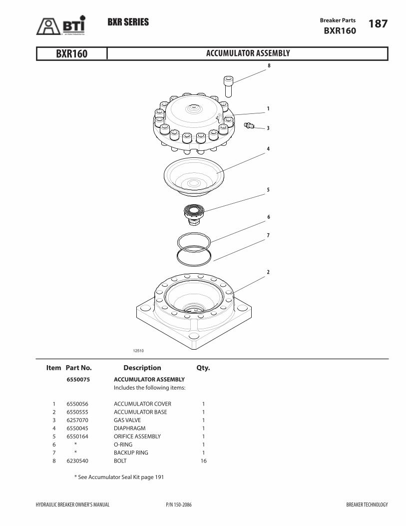
Breaker Parts 187BXR160
Item Part No. Description Qty.
ACCUMULATOR ASSEMBLY
6550075 ACCUMULATOR ASSEMBLY Includes the following items:
1 6550056 ACCUMULATOR COVER 1 2 6550555 ACCUMULATOR BASE 1 3 6257070 GAS VALVE 1 4 6550045 DIAPHRAGM 1 5 6550164 ORIFICE ASSEMBLY 1 6 * O-RING 1 7 * BACKUP RING 1 8 6230540 BOLT 16
* See Accumulator Seal Kit page 191
BXR160
BXR SERIES
HYDRAULIC BREAKER OWNER’S MANUAL P/N 150-2086 BREAKER TECHNOLOGY
12510
8
1
3
4
5
6
7
2

Breaker Parts188BXR160
Item Part No. Description Qty. Item Part No. Description Qty.
MASTER SEAL KIT
6550098 MASTER SEAL KIT Includes the following items:
1 6550065 ACCUMULATOR SEAL KIT 1 (See page 191) 2 6550100 CONTROL VALVE SEAL KIT 1 (See page 189) 3 6550099 INTERNAL SEAL KIT 1 (See page 190)
* NOTE: Seals not available separately Bladder sold separately.
BXR160
BXR SERIES
BREAKER TECHNOLOGY P/N 150-2086 HYDRAULIC BREAKER OWNER’S MANUAL
1
2
3

Breaker Parts 189BXR160
Item Part No. Description Qty. Item Part No. Description Qty.
CONTROL VALVE SEAL KIT
6550100 CONTROL VALVE SEAL KIT Includes the following items:
1 6550302 O-RING 12 2 6550303 O-RING 1 3 6550402 BACKUP RING 1 4 6550304 O-RING 2 5 6550403 BACKUP RING 2 6 6230546 O-RING 1 7 6550404 BACKUP RING 1 8 6130002 O-RING 2 9 6550405 BACKUP RING 2 10 6550306 O-RING 1 11 6550407 BACKUP RING 3 12 6550309 O-RING 3
13 6131539 O-RING 1 14 6550406 BACKUP RING 1 15 6501563 O-RING 1
NOTE: Items not available separately
BXR160
BXR SERIES
HYDRAULIC BREAKER OWNER’S MANUAL P/N 150-2086 BREAKER TECHNOLOGY

Breaker Parts190BXR160
Item Part No. Description Qty. Item Part No. Description Qty.
BXR SERIES
BREAKER TECHNOLOGY P/N 150-2086 HYDRAULIC BREAKER OWNER’S MANUAL
INTERNAL SEAL KITBXR160
6400099 INTERNAL SEAL KIT Includes the following items:
1 6360046 O-RING 1 2 6550308 O-RING 1 3 6550307 O-RING 2 4 6550082 QUAD RING 1 5 6550085 STEP SEAL 2 6 6550083OMS BUFFER SEAL 1 7 6550084OMS BUFFER SEAL 1 8 6550084 U-PACKING 1 9 6550086 DUST SEAL 1 10 6551134 O-RING 6
11 6500088 O-RING 5 12 6500007 O-RING 2 13 6700007 O-RING 4 14 6131539 O-RING 1 15 6550200 DUST SEAL 1 16 6551083 BUFFER SEAL 1 NOTE: Items not available separately
15
6
8
9
10
5
4
16
13
11
122 1
11
14
313
Orientation of the groove must be down.(Tool Side)
7

Breaker Parts 191BXR160
Item Part No. Description Qty.
ACCUMULATOR SEAL KIT
6550065 ACCUMULATOR SEAL KIT Includes the following items:
1 6550300 O-RING 1 2 6550400 BACKUP RING 1
NOTE: Items not available separately
BXR160
BXR SERIES
HYDRAULIC BREAKER OWNER’S MANUAL P/N 150-2086 BREAKER TECHNOLOGY

Breaker Parts192
Item Part No. Description Qty. Item Part No. Description Qty.
STROKE ADJUSTER ASSEMBLY
6550120 STROKE ADJUSTER ASSEMBLY Includes the following items:
1 6550020 STROKE ADJUSTER VALVE 1 2 6550021 STROKE ADJUSTER BUSHING 1 2A 6550021A STROKE ADJUSTER BUSHING 1 (OPTIONAL) 3 6550022 STROKE ADJUSTER CAP 1 4 6550023 BRASS WASHER 1 5 6550700 PLUG 1 6 6550309 O-RING 3 7 6131539 O-RING 1 8 6550302 O-RING 1 9 6550407 BACKUP RING 3 10 6550028 NPT PLUG 1
BXR SERIES
BREAKER TECHNOLOGY P/N 150-2086 HYDRAULIC BREAKER OWNER’S MANUAL
NOTE: Item 6 and Item 9 (o-rings and back-up rings) are not required if Stroke Adjuster Bushing (2A) is used.
ALL MODELS

Breaker Parts 193
Item Part No. Description Qty.
BXR SERIES
HYDRAULIC BREAKER OWNER’S MANUAL P/N 150-2086 BREAKER TECHNOLOGY
Breaker Parts 193
AIR VALVE ASSEMBLY
1 6557527 AIR VALVE ASSEMBLY 1 Includes the following items:
2 6557528 AIR VALVE CAP 1 3 6557529 AIR BALL 1 4 6557530 AIR SPRING 1 5 6557531 AIR BASE 1
ALL MODELS

Breaker Parts194
Item Part No. Description Qty. Item Part No. Description Qty.
BXR SERIES
BREAKER TECHNOLOGY P/N 150-2086 HYDRAULIC BREAKER OWNER’S MANUAL
REGENERATION VALVE
Breaker Parts194
Item Part No. Description Qty. 6550018 REGENERATION VALVE Includes the following items: 1 6550015 PILOT VALVE 1 1A 6550015L PILOT VALVE OPTION REF (For Cold Weather Application) 2 6550016 PILOT VALVE BUSHING 1 3 6550017 REGENERATION VALVE CAP 1 4 6501563 O-RING 1 5 6550027 CRUSHED BRASS WASHER 1
ALL MODELS
BXR SERIES

NOTES
195
HYDRAULIC BREAKER OWNER’S MANUAL P/N 150-2086 BREAKER TECHNOLOGY
BXR SERIES 195BXR SERIES

Auto-lube System Parts196
BXR AUTO-LUBE SYSTEM
BXR SERIES
BREAKER TECHNOLOGY P/N 150-2086 HYDRAULIC BREAKER OWNER’S MANUAL
ALL MODELS

Auto-lube System Parts 197
Item Part No. Description Qty.
BXR AUTO-LUBE SYSTEM
1012511 BXR AUTO-LUBE SYSTEM Includes the following items:
1 1012511-1 HYDRAULIC MOTOR 1 2 1012511-2 FILTER PLUG SCREW 1 3 1012511-3 CU-SEALING RING 8 4 1012511-4 THRUST PIECE 1 5 1012511-5 O-RING 1 6 1012511-6 STRAINER 1 7 1012511-7 DIAPHRAGM 1 8 1012511-8 THROTTLE 1 9 1012511-9 O-RING 1 10 1012511-10 SCREW PLUG 7 11 1012511-11 ECCENTRIC UNIT 1 12 1012533 CARTRIDGE 1 13 1012511-13 O-RING 1 14 1012511-14 O-RING 1 15 1012511-15 CARTRIDGE ADAPTER 1 16 1012511-16 FLAT SEAL 1 18 1012511-18 LOCKWASHER 2 19 1012511-19 HEX BOLT 2 25 1012511-25 PRESSURE RELIEF VALVE 1 26 1012511-26 CU-SEALING RING 1 27 1012511-27 SCREW PLUG 1 29 1012511-29 PUMPING ELEMENT 1 30 1012511-30 O-RING 1 31 1012511-31 BACKUP RING 1 32 1012511-32 PULLING DEVICE 1 33 1012511-33 O-RING 3 34 1012511-34 CU-SEALING RING 3 35 1012511-35 HEX SOCKET SCREW 3 36 1012511-36 SCALLOPED RING 1 37 1012511-37 VALVE SLEEVE 1
BXR SERIES
HYDRAULIC BREAKER OWNER’S MANUAL P/N 150-2086 BREAKER TECHNOLOGY

Auto-lube System Parts198
Item Part No. Description Qty. Item Part No. Description Qty.
BXR50 AUTO GREASE SYSTEM
444-0200 BXR50 AUTO GREASE SYSTEM Includes the following items:
1 1012511 GREASE PUMP 1 2 444-0201 GUARD MOUNT PLATE 1 3 444-0204 GUARD WELDMENT 1 4 1941035 FLAT WASHER 4 5 1931002 HEX NUT 4 6 1912555 HEX CAPSCREW 4 7 1942014 LOCK WASHER 4 8 1912603 HEX CAPSCREW 2 9 1942011 LOCK WASHER 2 10 1931000 HEX NUT 2 11 1941029 FLAT WASHER 2 12 1912602 HEX CAPSCREW 2
13 1942024 LOCK WASHER 2 14 1931058 HEX NUT 2 15 1941045 FLAT WASHER 2 16 HK-0063 BXR50 GREASE HOSE KIT 1 17 1800096 FITTING 1 18 1801478 FITTING 5
BXR SERIES
BREAKER TECHNOLOGY P/N 150-2086 HYDRAULIC BREAKER OWNER’S MANUAL

Auto-lube System Parts 199
Item Part No. Description Qty. Item Part No. Description Qty.
BXR65 AUTO GREASE SYSTEM
454-0200 BXR65 AUTO GREASE SYSTEM Includes the following items:
1 1012511 GREASE PUMP 1 2 444-0201 GUARD MOUNT PLATE 1 3 444-0204 GUARD WELDMENT 1 4 1941035 FLAT WASHER 4 5 1931002 HEX NUT 4 6 1912555 HEX CAPSCREW 4 7 1942014 LOCK WASHER 4 8 1912603 HEX CAPSCREW 2 9 1942011 LOCK WASHER 2 10 1931000 HEX NUT 2 11 1941029 FLAT WASHER 2 12 1912602 HEX CAPSCREW 2
13 1942024 LOCK WASHER 2 14 1931058 HEX NUT 2 15 1941045 FLAT WASHER 2 16 HK-00631 BXR65 GREASE HOSE KIT 1 17 1800096 FITTING 1 18 1801478 FITTING 5
BXR SERIES
HYDRAULIC BREAKER OWNER’S MANUAL P/N 150-2086 BREAKER TECHNOLOGY

Auto-lube System Parts200
Item Part No. Description Qty. Item Part No. Description Qty.
BXR85 AUTO GREASE SYSTEM
464-0200 BXR85 AUTO GREASE SYSTEM Includes the following items:
1 1012511 GREASE PUMP 1 2 464-0201 GUARD MOUNT PLATE 1 3 444-0204 GUARD WELDMENT 1 4 1941035 FLAT WASHER 4 5 1931002 HEX NUT 4 6 1912555 HEX CAPSCREW 4 7 1942014 LOCK WASHER 4 8 1912603 HEX CAPSCREW 2 9 1942011 LOCK WASHER 2 10 1931000 HEX NUT 2 11 1941029 FLAT WASHER 2 12 1912602 HEX CAPSCREW 2
13 1942024 LOCK WASHER 2 14 1931058 HEX NUT 2 15 1941045 FLAT WASHER 2 16 HK-00632 BXR85 GREASE HOSE KI 1 17 1800096 FITTING 1 18 1801478 FITTING 5
BXR SERIES
BREAKER TECHNOLOGY P/N 150-2086 HYDRAULIC BREAKER OWNER’S MANUAL
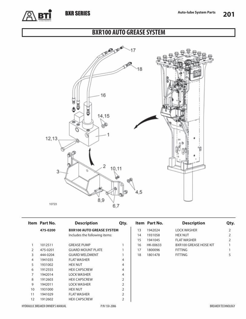
Auto-lube System Parts 201
Item Part No. Description Qty. Item Part No. Description Qty.
BXR100 AUTO GREASE SYSTEM
475-0200 BXR100 AUTO GREASE SYSTEM Includes the following items:
1 1012511 GREASE PUMP 1 2 475-0201 GUARD MOUNT PLATE 1 3 444-0204 GUARD WELDMENT 1 4 1941035 FLAT WASHER 4 5 1931002 HEX NUT 4 6 1912555 HEX CAPSCREW 4 7 1942014 LOCK WASHER 4 8 1912603 HEX CAPSCREW 2 9 1942011 LOCK WASHER 2 10 1931000 HEX NUT 2 11 1941029 FLAT WASHER 2 12 1912602 HEX CAPSCREW 2
13 1942024 LOCK WASHER 2 14 1931058 HEX NUT 2 15 1941045 FLAT WASHER 2 16 HK-00633 BXR100 GREASE HOSE KIT 1 17 1800096 FITTING 1 18 1801478 FITTING 5
BXR SERIES
HYDRAULIC BREAKER OWNER’S MANUAL P/N 150-2086 BREAKER TECHNOLOGY

Auto-lube System Parts202
Item Part No. Description Qty. Item Part No. Description Qty.
BXR120 AUTO GREASE SYSTEM
474-0200 BXR120 AUTO GREASE SYSTEM Includes the following items:
1 1012511 GREASE PUMP 1 2 474-0201 GUARD MOUNT PLATE 1 3 444-0204 GUARD WELDMENT 1 4 1941035 FLAT WASHER 4 5 1931002 HEX NUT 4 6 1912555 HEX CAPSCREW 4 7 1942014 LOCK WASHER 4 8 1912603 HEX CAPSCREW 2 9 1942011 LOCK WASHER 2 10 1931000 HEX NUT 2 11 1941029 FLAT WASHER 2 12 1912602 HEX CAPSCREW 2
13 1942024 LOCK WASHER 2 14 1931058 HEX NUT 2 15 1941045 FLAT WASHER 2 16 HK-00634 BXR120 GREASE HOSE KIT 1 17 1800096 FITTING 1 18 1801478 FITTING 5
BXR SERIES
BREAKER TECHNOLOGY P/N 150-2086 HYDRAULIC BREAKER OWNER’S MANUAL

Auto-lube System Parts 203
Item Part No. Description Qty. Item Part No. Description Qty.
BXR160 AUTO GREASE SYSTEM
481-0200 BXR160 AUTO GREASE SYSTEM Includes the following items:
1 1012511 GREASE PUMP 1 2 481-0201 GUARD MOUNT PLATE 1 3 444-0204 GUARD WELDMENT 1 4 1941035 FLAT WASHER 4 5 1931002 HEX NUT 4 6 1912555 HEX CAPSCREW 4 7 1942014 LOCK WASHER 4 8 1912603 HEX CAPSCREW 2 9 1942011 LOCK WASHER 2 10 1931000 HEX NUT 2 11 1941029 FLAT WASHER 2 12 1912602 HEX CAPSCREW 2
13 1942024 LOCK WASHER 2 14 1931058 HEX NUT 2 15 1941045 FLAT WASHER 2 16 HK-00635 BXR160 GREASE HOSE KIT 1 17 1800096 FITTING 1 18 1801478 FITTING 5
BXR SERIES
HYDRAULIC BREAKER OWNER’S MANUAL P/N 150-2086 BREAKER TECHNOLOGY

NOTES
204
BREAKER TECHNOLOGY P/N 150-2086 HYDRAULIC BREAKER OWNER’S MANUAL
BXR SERIES

Warranty 205Hydraulic Breaker Warranty Policy
HYDRAULIC BREAKER OWNER’S MANUAL P/N 150-2086 BREAKER TECHNOLOGY
BXR SERIES
YCI
LOP
YT
NARRA
WWWAARRRRAANNTTYYPPOOLLIICCYY
REV 09/04
1. BREAKERTECHNOLOGY INC. Company (hereinafter referred to as "BTI") warrants this product against defects inmaterials and workmanship for a period of twelve (12) months or 2000 hours from the date of installation, or 18 months fromthe date of shipment, whichever comes first. This warranty will become void if, (a) replacement parts not manufactured byBTI are used, and (b) non-standard length tools are used. This warranty does not cover o-rings, seals, fittings, hoses, breakertools or other items considered normal wear items. These are covered by the Limited Warranty period of thirty (30) days.Warranty for propriety items such as valves, filters, installation kits, and componentry that are not manufactured by BTI, willbe governed by the warranty terms of their manufacturer. This warranty is void if BTI's standard installation specificationsand procedures are not adhered to.
2. BTI will authorize return of any defective components or sufficient evidence of such defect to a BTI warehouse. Suchcomponents or such evidence must clearly show that the defect was caused by faulty material or poor workmanship. Warrantyclaim will be accepted only if it is submitted on a proper claims form with proof of purchase and received within sixty (60)days from the date of discovery of the defect. Warranty claims will be considered only if the "Installation Notice" has beenduly filled in and returned to BTI's within thirty (30) days from the date of installation.
3. BTI will at it's option, repair or refurbish the defective part(s) without charge to the initial user or may elect to issue full orpartial credit toward the purchase of a new part(s). The extent of credit issued, which will be in the form of a "Credit Memo",will be determined by pro-rating against the normal life of the part(s) in question.
4. BTI is not responsible for mileage, travel time, travel expenses, overtime labor, and any freight expenses required tofacilitate the repair.
5. This warranty does not apply if the product has been damaged by accident, abuse, misuse, misapplication or neglect, or as aresult of service, disassembly or modification, without BTI's express authorization.
6. BTI assumes no liability beyond the replacement of defective parts or materials and/or the correction of such defectiveparts or materials.
7. BTI neither assumes nor authorizes any other person to assume for it any liability in connection with the sale of itsproducts other than that specifically stated herein.
8. THIS WARRANTY IS EXPRESSLY IN LIEU OFANYANDALL OTHERWARRANTIES. EXCEPTAS EXPRESSLYSET FORTH HEREIN, BTI MAKES NO REPRESENTATION ORWARRANTY, STATUTORY, EXPRESS OR IMPLIED,WITH RESPECT TO THE PRODUCTS MANUFACTUREDAND/OR SUPPLIED BY BTI, WHETHERAS TOMERCHANTABILITY, FITNESS FORA PARTICULAR PURPOSE ORANYOTHER MATTER. IN NO EVENT,INCLUDING IN THE CASE OFACLAIM OF NEGLIGENCE, SHALL BTI BE LIABLE FOR INCIDENTAL ORCONSEQUENTIAL DAMAGES.
Hydraulic Breaker Warranty Policy
Breaker Technology, Inc.30625 Solon Industrial Drive,Solon Ohio,44139 U.S.A.PH. 440-248-7168FAX. 440-248-8645
Breaker Technology, Inc.3464 Durahart St.Riverside, California92507 U.S.A.PH. 951-369-0878FAX. 951-369-8281
Breaker Technology Ltd.35 Elgin St.Thornbury Ontario,N0H 2P0 CanadaPH. 519-599-2015FAX. 519-599-6803
# 10249-ENG-0904

Reference Information206Hardness of Rock
BREAKER TECHNOLOGY P/N 150-2086 HYDRAULIC BREAKER OWNER’S MANUAL
BXR SERIES
Very HardHardSoft MediumTalcSlateGypsum rockAsbestos rockSoft limestone
LimestoneDolomiteSandstoneCopper Ore
GraniteQuartziteIron oreTrap rockGravelGabro
Iron ore (Taconite)GraniteGrantic gravelTrap rock
1
2
3
4
5
- Talc
- Gypsum
- Clacite
- Flourite
- Apatite
6
7
8
9
10
- Orthoclase
- Quartz
- Topaz
- Corundum
- Diamond
MOHSScale of Hardness
Scratched with: Hardness:
Fingernail . . . . . . . . . . little overCopper coin. . . . . . . . . aboutPocket knife . . . . . . . . little overWindow glass . . . . . . .Steel file . . . . . . . . . . .
235
5.56.5
Testing(you can do in the field)
Reference InformationHardness of Rock

Reference Information 207Viscosity Conversion Table
HYDRAULIC BREAKER OWNER’S MANUAL P/N 150-2086 BREAKER TECHNOLOGY
BXR SERIES
0.100.150.200.250.300.400.500.600.700.800.901.001.201.401.601.802.002.202.402.602.803.003.203.403.603.804.004.204.404.604.805.005.506.007.008.009.0010.0011.00
608010013016021026032037043048053058069079090010001100120012801380147515301630173018501950205021602270238024802660290033753880430046005200
5470981061251652032452863273684094855706457358159009851060114012351300139014651550163516951790183719502045224024332850327036904000
30.835.040.044.747.858.266.876.486.395.8104.6113.5124.5137.5143.2151.8161.3171.5180.0189.5199.5209.5218.4228.9239.4259.7287.6332.4380.1427.8479.6
30.0534.0037.8541.9049.8057.9066.0074.1582.3590.0097.75105.60114.90123.75131.65139.50149.00157.55166.35171.65183.50188.65198.75208.85229.95248.50289.60329.75368.85408.70
101520253040506070809010012014016018020022024026028030032034036038040042044046048050055060070080090010001100
2730323743505764
1112131415161718202223253032374145
202530353950
3034374144526068
1617181920222427303437414958667482
101214161820232528303234363941434648505254576368
1011131416171819212224252628293032333436374044515864
1011121314151617181920212223242527303540454955
192021232426273134384044
581012141822252831323441455054586265687074
A-4A-3
A-2A-1A
B
C
DEFG
HIJ
KLMNO
P
QR
STU
VW
30333537384043464850525456585960
62
64
66676869717477818588
1517182124293339445062
121519252933364145505866
POISECENTIPOISE
DUPONT PARLIN7
DUPONT PARLIN10
FISHER 1
FISHER 2
FORD CUP 3
FORD CUP 4
GARDNER HOLDT BUBBLE
UKSTINUSBERK SAYBOLT
UNIVERSAL SSU
ZAHN 1ZAHN 2
ZAHN 3ZAHN 4
ZAHN 5SEARS CRAFTSMAN CUP
REDWOOD No. 2SECCES1.oNDOOWDER SAY
BOLTFUROL SEC
Viscosity Conversion Table

Reference Information208Fluid Grade Systems
BREAKER TECHNOLOGY P/N 150-2086 HYDRAULIC BREAKER OWNER’S MANUAL
BXR SERIESReference Information
Fluid Grade Systems
BREAKER TECHNOLOGY P/N 150-2086 HYDRAULIC BREAKER OWNER’S MANUAL
BXR SERIES
4000
30002500
2000
1500
1000
800
600500
400
300250
200
150
100
55
90
70
1900
1250
680 8
7
6
5
4
3
2
1
460
320
220
150
100
40
46
32
22
15
10
40
30
20
16
109
8
7
6
5
4
800
600500
400350300250
200
150
100
80
60
50
40
30
20
15
10
200
150
125
100
90
80
70
60
50
45
40
55
50
40
30
20
10W
5W
140
90
85W
80W
75W
GRADE SYSTEMS
KinematicViscosities
SayboltViscosities
cSt40°C
cSt100°C
SUS210°F
SUS100°FISO AGMA
SAEENGINEOIL
SAEGEAROIL
Viscosities can be related horizontally only. For example, the followingoilshavesimilar viscosities: ISO460,AGMA7andSAEGEAROIL140.
The viscosity/temperature relationships are based on 95 VI oils and areusableonly formonogradeengineoils, gearoilsandother95VIoils.
Crankcase oils and gear oils are based on 100°C viscosity. The “W”grades are classified on low temperature properties. ISOoils andAGMAgradesarebasedon40 Cviscosity.°
Fluid Grade Systems

Reference Information 209Box Housing Measurement Data Sheet
HYDRAULIC BREAKER OWNER’S MANUAL P/N 150-2086 BREAKER TECHNOLOGY
BXR SERIES Reference Information
Box Housing Measurement Data Sheet
HYDRAULIC BREAKER OWNER’S MANUAL P/N 150-2086 BREAKER TECHNOLOGY
BXR SERIES
Box Housing Measurement Data Sheet
C
A
D
B
Box Housing MeasurementData Sheet
Date of Service: ____________
Reference No: ______________
Breaker Model: ____________
Serial No: _________________
C D
AB
Measure minimum dimension inside housing at positionsA, B, C, & D.
Position A
Position B
Position C
Position D
Position A
Position B
Position C
Position D
Position A
Position B
Position C
Position D
Position A
Position B
Position C
Position D
Position A
Position B
Position C
Position D
Measure maximum dimension outside breaker body at positionsA, B, C, & D.
Measure support pad thickness (qty 2) for each position A, B, C, & D.
STEP 1
STEP 2
STEP 3
Add Step 2 and 3 together, then add .006 in (0,15 mm). Do this for each position A, B, C, & D.
STEP 4
Subtract Step 4 from Step 1 for eachposition A, B, C, & D.This is the required shim thickness.Position equal number of shims on both sides if possible.
STEP 5
0LQLPXP�+RXVLQJ�,QVLGH�'LPHQVLRQ
0D[LPXP�%UHDNHU�'LPHQVLRQ
6XSSRUW�3DG�7KLFNQHVV�7RWDO��TW\���
$GG�6WHS����6WHS�����������LQ�������PP�
7RWDO�6KLP�7KLFNQHVV�5HTXLUHG

Reference Information210Service Report
BREAKER TECHNOLOGY P/N 150-2086 HYDRAULIC BREAKER OWNER’S MANUAL
BXR SERIES
Service ReportService Report
Date of Service:____________Reference No: ____________
:Signature of Inspector _ _ _ _ _ _ _ _ _ _
No:Part No:
Qty:
Inspector’s Comment: Customer’s Comment:
:Signature of Customer _ _ _ _ _ _ _ _ _ _
Location of Equipment: _ _ _ _ _ _ _ _ _ _
Customer: _ _ _ _ _ _ _ _ _ _ _ _ _ _ _ Distributor: _ _ _ _ _ _ _ _ _ _ _ _ _ _ _
- Evidence- Detail Report ( )- Photos ( )- Parts Returned ( )
Base Carrier:
Manufacturer:
Operating Hours:
Model:
Remarks:
Breaker:
Model:
Gas Pressure:
Operating Hours:
Serial No:
Bracket Type:
Delivered Date:
Condition of Breaker:
Oil Flow:
Relief Set Pressure:
Operating Pressure:
Blows per Minute:
GPM
psi
psi
LPM
bar
bar
BPM

Reference Information 211Receiving Inspection Report
HYDRAULIC BREAKER OWNER’S MANUAL P/N 150-2086 BREAKER TECHNOLOGY
BXR SERIES
Receiving Inspection ReportReceiving Inspection Report
Receiving Date: ____________Inspection Date: ____________
Check Inspection Items:Good:Bad:Correction made:
*%
&
Model
Paint
Tool Box
Serial No.
Spare Parts
GasRecharge Kit
Main body ( )Bracket ( )
BTI use only:
Inspector’s Comments:
Distributor:
Signature of Customer:
_ _ _ _ _ _ _ _ _ _ _ _ _ _ _ _
_ _ _ _ _ _ _ _ _ _

Reference Information212Delivery Report
BREAKER TECHNOLOGY P/N 150-2086 HYDRAULIC BREAKER OWNER’S MANUAL
BXR SERIES
Delivery Report Delivery Report
Date Received:____________Reference No: ____________
:
Title/Position:
Signature of Customer _ _ _ _ _ _ _ _ _ _
_ _ _ _ _ _ _ _ _ _ _ _ _ _ _
I hereby acknowledge that the breaker has been delivered in satisfactory condition and operatesproperly; and that I received the owner’s manual complete with operation, maintenance, and partslisting; and that all aspects of the standard warranty have been fully explained to me.
Installation Date:: _ _ _ _ _ _ _ _ _ _ _ _ Expiry Date See Warranty:
Distributor:
Customer:
Breaker:
Model: _ _ _ _ _ _ _ _ _ _ _ _ _ _ _ _ _ _ _ _ Serial No: _ _ _ _ _ _ _ _ _ _ _ _ _ _ _ _ _ _ _ _
Operating Weight: _ _ _ _ _ _ _ _ _ _ _ _ _ _ _ _ _ _ _ _ _ _ _ _ _ _ _ _ _ _Operating Hours:
Operating Pressure: _ _ _ _ _ _ _ _ _ _ _ _ _ Relief Set Pressure: _ _ _ _ _ _ _ _ _ _ _ _ _ _ _
Gas Pressure: _ _ _ _ _ _ _ _ _ _ _ _ _ _ _ _ Others: _ _ _ _ _ _ _ _ _ _ _ _ _ _ _ _ _ _ _ _ _
STRA
PSE
TALP

Reference Information 213Conversion factors
HYDRAULIC BREAKER OWNER’S MANUAL P/N 150-2086 BREAKER TECHNOLOGY
BXR SERIES
Conversion factors
SI Unit of Measure
Millimeter
Bar
Bar
Liters per minute (l/min)
Liters per second (l/sec)
Cubic decimeters per second
Newton (N)
Kilogram (kg)
Second (s)
Liter (l)
Degrees Celsius (°C)
Kilogram - meters �NJ�P�
Kilowatt (kW)
Revolutions per minute (rpm) Revolutions per minute (rpm)
Hertz (Hz)
Milliliters per revolution (ml/rev)
Centistokes (cSt)
Meter per second (m/s)
Deka newtons per sq.millimeter
(assumed to be “gauge”
a value less than 1.0 is(
US Unit of Measure
Inch
Pounds per sq. inch
Inches of mercury (in Hg)
Gallons per minute
Cubic feet per minute (cfm)
Pound (f) lb(f)
Pound (m) lb(m)
Second (s)
Gallon (gal) U.S.
Degrees Fahrenheit F
Foot-pounds �IW�OE�
Horsepower (hp)
Cycles per second (cps)
Cubic inches per revolution
Saybolt (SUS)
Feet per second (fps)
Pounds per sq.inch (psi)
(in)
Gallons per minute
(° )
Conversion
1 in. = 25.4 mm
1 Bar = 14.5 psi
1 in. Hg (@ 60°F) = 0.034 bar
1 gpm = 3.79 l/m
1 gpm = 0.063 l/sec
1 dm3/s = 2.12 scfm
1 lb(f) = 4.44 N
1 kg = 2.20 lb(m)
1 U.S. gal = 3.79 l
°C = 5/9 (°F -32)
1 NJ�m = 7.23 ft-lb
1 kW = 1.34 hp
1 Hz = 1 cps
1 ml/rev = 0.061 cipr
cSt = 4.635 SUS
1 m/s = 3.28 fps
1 da N/mm2 = 1450 psi
Quantity
Length
Pressure
Flow
Flow
Flow
Force
Mass
Time
Volume
Temperature
Torque
Power
Shaft speed
Frequency
Displacement
Kinetic Viscosity
Velocity
Material Stress
Pressure
unless stated otherwis)
shown as a decimal, i.e. 0.95 bar)
( )dm /s3
(da N/mm2)
(psi or psig)
( )gpm -U.S.
( )gpm -U.S.
( )cip
NOI

NOTES
214
BREAKER TECHNOLOGY P/N 150-2086 HYDRAULIC BREAKER OWNER’S MANUAL
BXR SERIES