
HYDRAULIC AUTOMATION FOR SWING GATES - BFT - P4,5.pdf · 192 D811223_03 AUTOMATION FOR SWING GATES...
10
P 7 P 4,5 HYDRAULIC AUTOMATION FOR SWING GATES D811223 07-11-00 Vers. 03
-
Upload
truongliem -
Category
Documents
-
view
217 -
download
1
Transcript of HYDRAULIC AUTOMATION FOR SWING GATES - BFT - P4,5.pdf · 192 D811223_03 AUTOMATION FOR SWING GATES...

P 7P 4,5
HYDRAULICAUTOMATION FOR
SWING GATES
D811223 07-11-00 Vers. 03
192
D81
1223
_03
AUTOMATION FOR SWING GATESAUTOMATION FOR SWING GATES
P 7 - P 4,5P 7 - P 4,5Thank you for buying this product, our company is sure that you will be morethan satisfied with the product’s performance. The product is supplied witha “Warnings” leaflet and an “Instruction booklet”. These should both beread carefully as they provide important information about safety, installation,operation and maintenance. This product complies with the recognisedtechnical standards and safety regulations. We declare that this product isin conformity with the following European Directives: 89/336/EEC and 73/23/EEC and 98/37/EEC and following amendments.
1) GENERAL SAFETYWARNING! An incorrect installation or improper use of the product cancause damage to persons, animals or property.• The “Warnings” leaflet and the “Instruction booklet” supplied with this
product should be read carefully as they provide important informationabout safety, installation, operation and maintenance.
• Scrap packing materials (plastic, cardboard, polystyrene etc) accordingto the provisions set out by current standards. Keep nylon or polystyrenebags out of children’s reach.
• Keep the instructions with the technical brochure for future reference.• This product was exclusively designed and manufactured for the use
specified in the present documentation. Uses not specified in thisdocumentation could cause damage to the product and be dangerous.
• The Company declines all responsibility for any consequences resultingfrom the product being used improperly or differently from whatever isspecified in the present documentation.
• Do not install the product in an explosive environment.• The construction components of this product must comply with the
following European Directives: 89/336/CEE, 73/23/EEC, 98/37 andfollowing amendments. As for all non-EEC countries, the abovementioned standards as well as the current national standards shouldbe respected in order to have a good safety level.
• The Company declines all responsibility for any consequences resultingfrom failure to observe Good Technical Practice when constructingclosing structures (door, gates etc.), as well as from any deformationwhich might occur during use.
• The installation must comply with the provisions set out by the followingEuropean Directives: 89/336/CEE, 73/23/EEC, 98/37/EEC and followingamendments.
• Disconnect the electrical power supply before carrying out any operationson the plant. Also disconnect any buffer batteries, if fitted.
• Fit an omnipolar circuit breaker or thermal magnetic circuit breaker onthe mains power supply, having a contact opening distance equal to orgreater than 3 mm.
• Check that a differential switch with a 0.03A threshold is fitted just beforethe power supply mains.
• Check that earthing is carried out correctly: connect all metal parts forclosure (doors, gates etc.) and all system components provided, with anearth terminal.
• Fit all the safety devices (photocells, electric edges etc.) which areneeded to protect the area from any danger caused by squashing,conveying and shearing.
• Position at least one light signal device (blinker) where it can be easilyseen, and fix a Warning sign to the structure.
• The Company declines all responsibility with respect to the automation safetyand good operation when other manufacturers’ components are used.
• Only use original parts for any maintenance or repair operation.• Do not modify the automation components, unless explicitly authorised
by the Company.• Instruct the product user about the control systems provided and the
manual opening operation in case of emergency.• Do not allow persons or children to remain in the automation operation area.• Keep radio control or other control devices out of children’s reach, in
order to avoid unintentional automation activation.• The user must avoid any attempt to carry out work or repair on the
automation system, but only request assistance from qualified personnel.• Anything which is not expressly provided for in the present instructions,
is not allowed.
2) GENERAL OUTLINEA compact sturdy hydraulic piston, available in various versions accordingto the user’s requirements and type of operation. All models are suppliedwithout locks (reversible), and an electric lock is required to keep themblocked. To make the manual manoeuvre easier, the lock can be releasedby means of a knob which can be reached using the appropriate key.The pushing force is adjusted with extreme precision by means of two by-pass valves which provide antisquash safety. The end-of-stroke operationis electronically set in the control panel by means of a timer.All models are available with slow-down function during the closing phase.
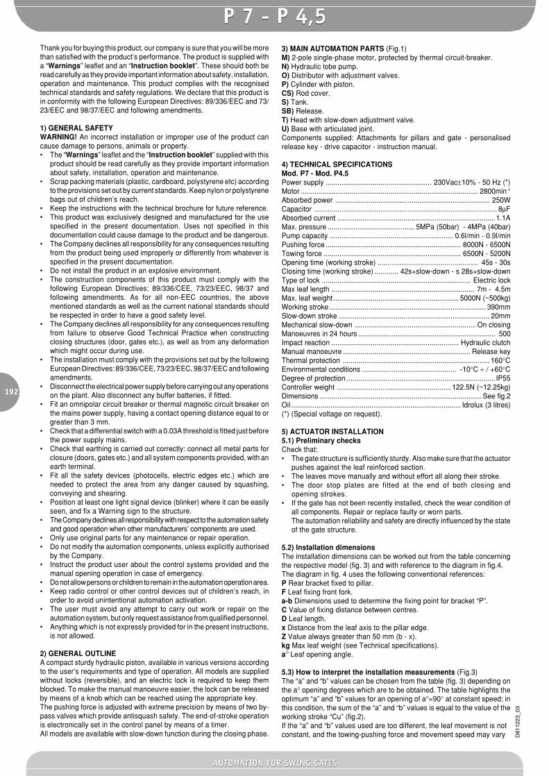
3) MAIN AUTOMATION PARTS (Fig.1)M) 2-pole single-phase motor, protected by thermal circuit-breaker.N) Hydraulic lobe pump.O) Distributor with adjustment valves.P) Cylinder with piston.CS) Rod cover.S) Tank.SB) Release.T) Head with slow-down adjustment valve.U) Base with articulated joint.Components supplied: Attachments for pillars and gate - personalisedrelease key - drive capacitor - instruction manual.
4) TECHNICAL SPECIFICATIONSMod. P7 - Mod. P4.5Power supply ...................................................... 230Vac±10% - 50 Hz (*)Motor ........................................................................................... 2800min-1
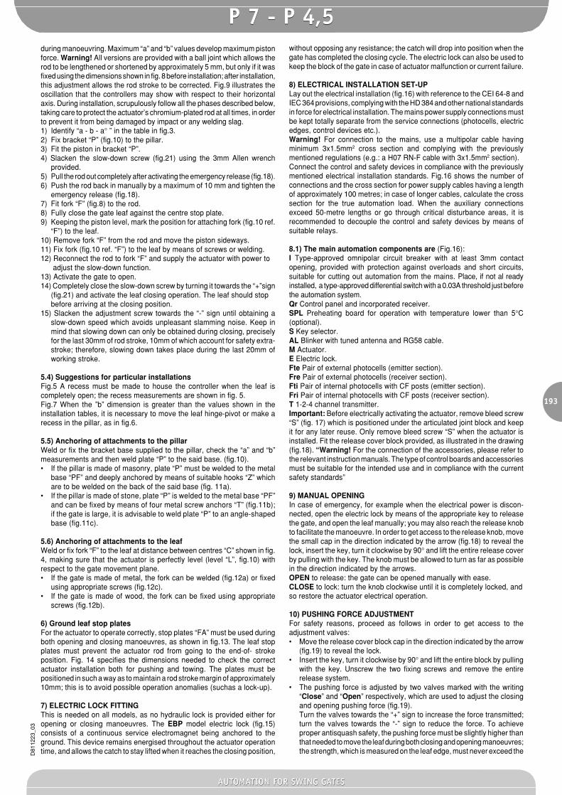
Absorbed power ............................................................................... 250WCapacitor .............................................................................................. 8µFAbsorbed current .................................................................................1.1AMax. pressure ............................................ 5MPa (50bar) - 4MPa (40bar)Pump capacity ............................................................... 0.6l/min - 0.9l/minPushing force ..................................................................... 8000N - 6500NTowing force ...................................................................... 6500N - 5200NOpening time (working stroke) ................................................... 45s - 30sClosing time (working stroke) ............ 42s+slow-down - s 28s+slow-downType of lock ............................................................................ Electric lockMax leaf length ......................................................................... 7m - 4.5mMax. leaf weight ................................................................ 5000N (~500kg)Working stroke ................................................................................ 390mmSlow-down stroke ............................................................................. 20mmMechanical slow-down .............................................................. On closingManoeuvres in 24 hours ...................................................................... 500Impact reaction ................................................................. Hydraulic clutchManual manoeuvre ................................................................. Release keyThermal protection ........................................................................... 160°CEnvironmental conditions ................................................ -10°C ÷ / +60°CDegree of protection ............................................................................ IP55Controller weight ..........................................................122.5N (~12.25kg)Dimensions ...................................................................................See fig.2Oil ....................................................................................... Idrolux (3 litres)(*) (Special voltage on request).
5) ACTUATOR INSTALLATION5.1) Preliminary checksCheck that:• The gate structure is sufficiently sturdy. Also make sure that the actuator
pushes against the leaf reinforced section.• The leaves move manually and without effort all along their stroke.• The door stop plates are fitted at the end of both closing and
opening strokes.• If the gate has not been recently installed, check the wear condition of
all components. Repair or replace faulty or worn parts.The automation reliability and safety are directly influenced by the stateof the gate structure.
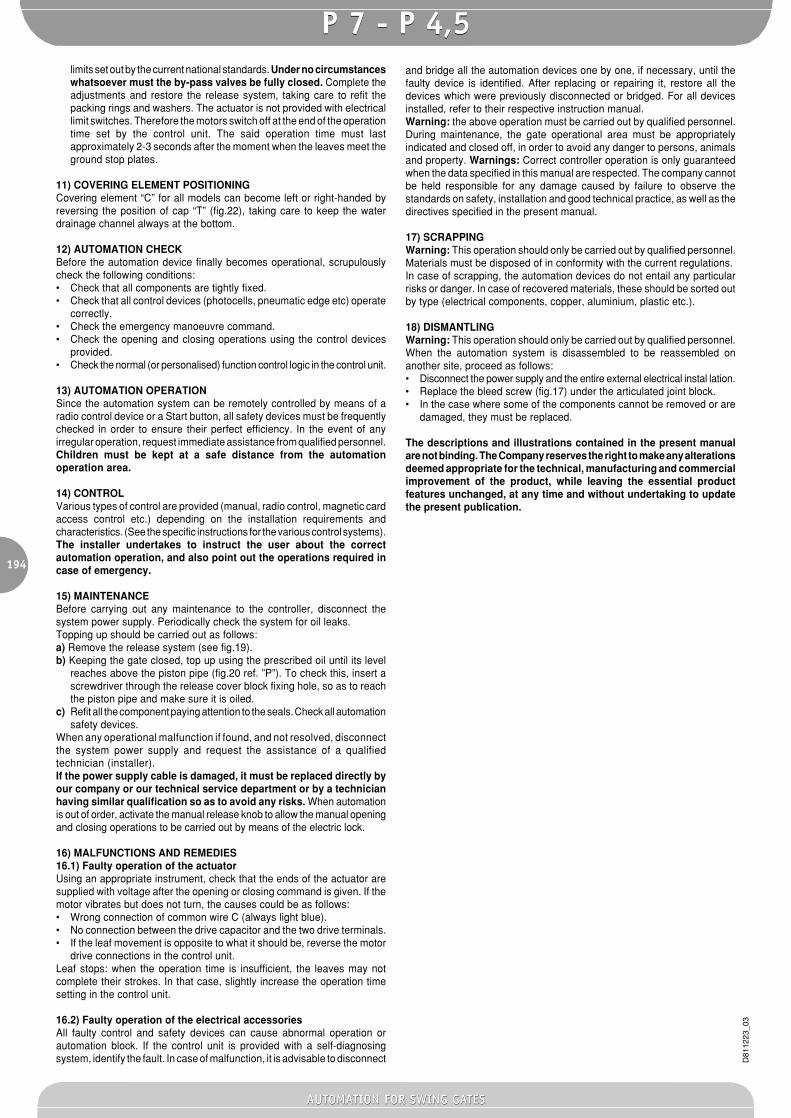
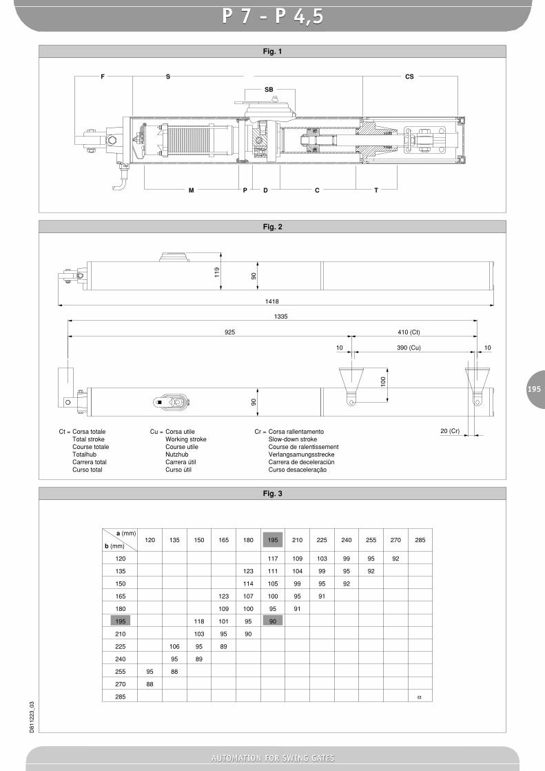
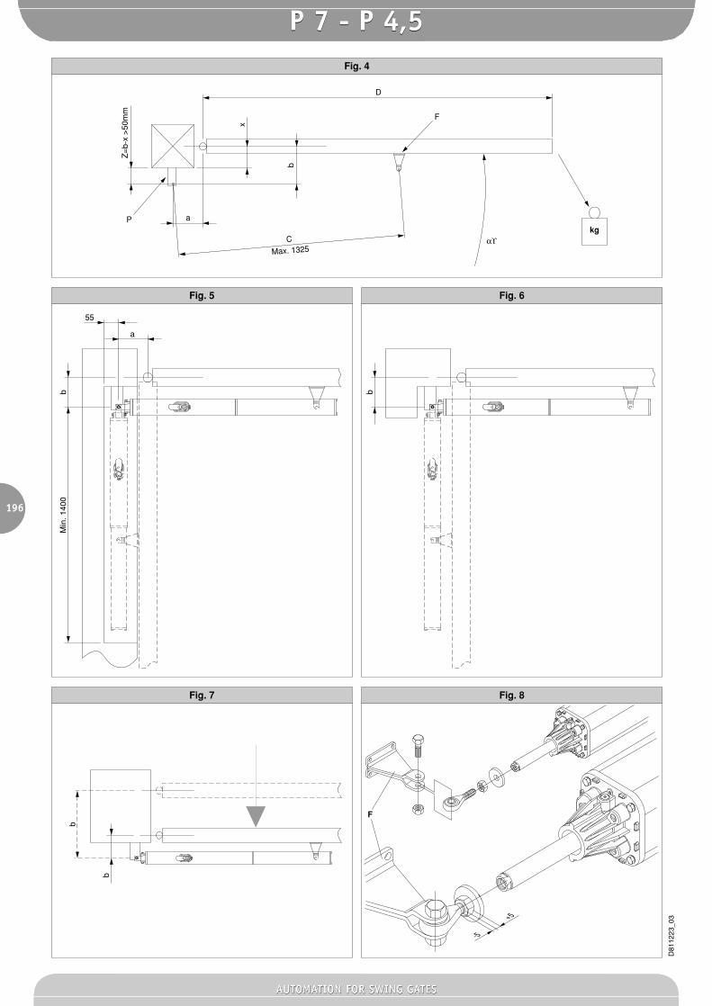
5.2) Installation dimensionsThe installation dimensions can be worked out from the table concerningthe respective model (fig. 3) and with reference to the diagram in fig.4.The diagram in fig. 4 uses the following conventional references:P Rear bracket fixed to pillar.F Leaf fixing front fork.a-b Dimensions used to determine the fixing point for bracket “P”.C Value of fixing distance between centres.D Leaf length.x Distance from the leaf axis to the pillar edge.Z Value always greater than 50 mm (b - x).kg Max leaf weight (see Technical specifications).a° Leaf opening angle.
5.3) How to interpret the installation measurements (Fig.3)The “a” and “b” values can be chosen from the table (fig. 3) depending onthe a° opening degrees which are to be obtained. The table highlights theoptimum “a” and “b” values for an opening of a°=90° at constant speed; inthis condition, the sum of the “a” and “b” values is equal to the value of theworking stroke “Cu” (fig.2).If the “a” and “b” values used are too different, the leaf movement is notconstant, and the towing-pushing force and movement speed may vary
193
D81
1223
_03
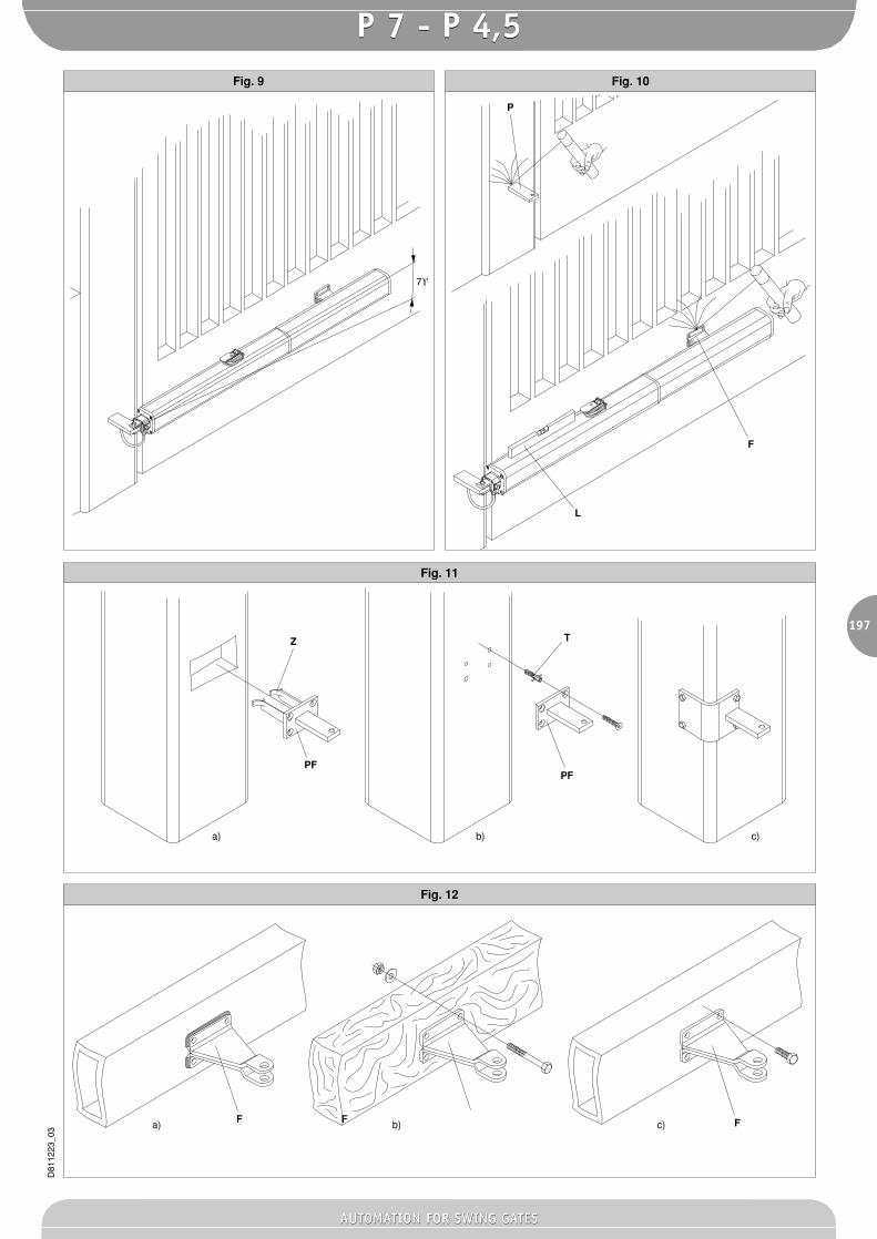
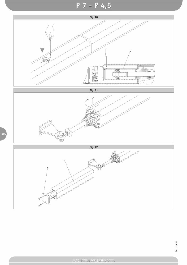
during manoeuvring. Maximum “a” and “b” values develop maximum pistonforce. Warning! All versions are provided with a ball joint which allows therod to be lengthened or shortened by approximately 5 mm, but only if it wasfixed using the dimensions shown in fig. 8 before installation; after installation,this adjustment allows the rod stroke to be corrected. Fig.9 illustrates theoscillation that the controllers may show with respect to their horizontalaxis. During installation, scrupulously follow all the phases described below,taking care to protect the actuator’s chromium-plated rod at all times, in orderto prevent it from being damaged by impact or any welding slag.1) Identify “a - b - a° ” in the table in fig.3.2) Fix bracket “P” (fig.10) to the pillar.3) Fit the piston in bracket “P”.4) Slacken the slow-down screw (fig.21) using the 3mm Allen wrench
provided.5) Pull the rod out completely after activating the emergency release (fig.18).6) Push the rod back in manually by a maximum of 10 mm and tighten the
emergency release (fig.18).7) Fit fork “F” (fig.8) to the rod.8) Fully close the gate leaf against the centre stop plate.9) Keeping the piston level, mark the position for attaching fork (fig.10 ref.
“F”) to the leaf.10) Remove fork “F” from the rod and move the piston sideways.11) Fix fork (fig.10 ref. “F”) to the leaf by means of screws or welding.12) Reconnect the rod to fork “F” and supply the actuator with power to
adjust the slow-down function.13) Activate the gate to open.14) Completely close the slow-down screw by turning it towards the “+”sign
(fig.21) and activate the leaf closing operation. The leaf should stopbefore arriving at the closing position.
15) Slacken the adjustment screw towards the “-” sign until obtaining aslow-down speed which avoids unpleasant slamming noise. Keep inmind that slowing down can only be obtained during closing, preciselyfor the last 30mm of rod stroke, 10mm of which account for safety extra-stroke; therefore, slowing down takes place during the last 20mm ofworking stroke.
5.4) Suggestions for particular installationsFig.5 A recess must be made to house the controller when the leaf iscompletely open; the recess measurements are shown in fig. 5.Fig.7 When the ”b” dimension is greater than the values shown in theinstallation tables, it is necessary to move the leaf hinge-pivot or make arecess in the pillar, as in fig.6.
5.5) Anchoring of attachments to the pillarWeld or fix the bracket base supplied to the pillar, check the “a” and “b”measurements and then weld plate “P” to the said base. (fig.10).• If the pillar is made of masonry, plate “P” must be welded to the metal
base “PF” and deeply anchored by means of suitable hooks “Z” whichare to be welded on the back of the said base (fig. 11a).
• If the pillar is made of stone, plate “P” is welded to the metal base “PF”and can be fixed by means of four metal screw anchors “T” (fig.11b);if the gate is large, it is advisable to weld plate “P” to an angle-shapedbase (fig.11c).
5.6) Anchoring of attachments to the leafWeld or fix fork “F” to the leaf at distance between centres “C” shown in fig.4, making sure that the actuator is perfectly level (level “L”, fig.10) withrespect to the gate movement plane.• If the gate is made of metal, the fork can be welded (fig.12a) or fixed
using appropriate screws (fig.12c).• If the gate is made of wood, the fork can be fixed using appropriate
screws (fig.12b).
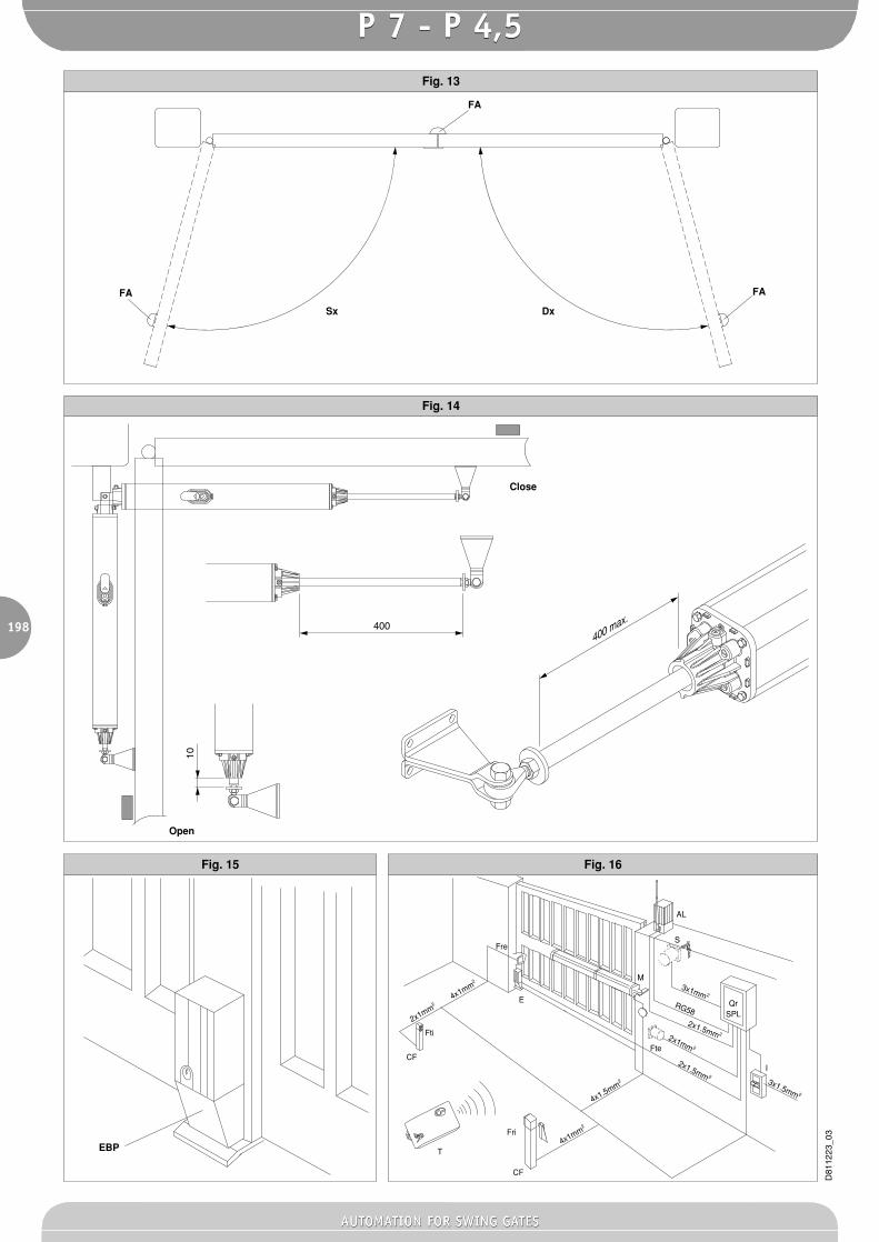
6) Ground leaf stop platesFor the actuator to operate correctly, stop plates “FA” must be used duringboth opening and closing manoeuvres, as shown in fig.13. The leaf stopplates must prevent the actuator rod from going to the end-of- strokeposition. Fig. 14 specifies the dimensions needed to check the correctactuator installation both for pushing and towing. The plates must bepositioned in such a way as to maintain a rod stroke margin of approximately10mm; this is to avoid possible operation anomalies (suchas a lock-up).
7) ELECTRIC LOCK FITTINGThis is needed on all models, as no hydraulic lock is provided either foropening or closing manoeuvres. The EBP model electric lock (fig.15)consists of a continuous service electromagnet being anchored to theground. This device remains energised throughout the actuator operationtime, and allows the catch to stay lifted when it reaches the closing position,
without opposing any resistance; the catch will drop into position when thegate has completed the closing cycle. The electric lock can also be used tokeep the block of the gate in case of actuator malfunction or current failure.
8) ELECTRICAL INSTALLATION SET-UPLay out the electrical installation (fig.16) with reference to the CEI 64-8 andIEC 364 provisions, complying with the HD 384 and other national standardsin force for electrical installation. The mains power supply connections mustbe kept totally separate from the service connections (photocells, electricedges, control devices etc.).Warning! For connection to the mains, use a multipolar cable havingminimum 3x1.5mm2 cross section and complying with the previouslymentioned regulations (e.g.: a H07 RN-F cable with 3x1.5mm2 section).Connect the control and safety devices in compliance with the previouslymentioned electrical installation standards. Fig.16 shows the number ofconnections and the cross section for power supply cables having a lengthof approximately 100 metres; in case of longer cables, calculate the crosssection for the true automation load. When the auxiliary connectionsexceed 50-metre lengths or go through critical disturbance areas, it isrecommended to decouple the control and safety devices by means ofsuitable relays.
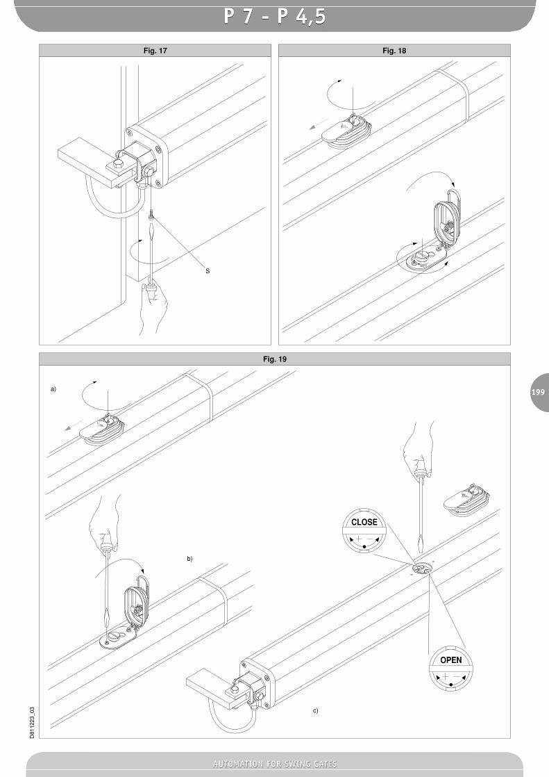
8.1) The main automation components are (Fig.16):I Type-approved omnipolar circuit breaker with at least 3mm contactopening, provided with protection against overloads and short circuits,suitable for cutting out automation from the mains. Place, if not al readyinstalled, a type-approved differential switch with a 0.03A threshold just beforethe automation system.Qr Control panel and incorporated receiver.SPL Preheating board for operation with temperature lower than 5°C(optional).S Key selector.AL Blinker with tuned antenna and RG58 cable.M Actuator.E Electric lock.Fte Pair of external photocells (emitter section).Fre Pair of external photocells (receiver section).Fti Pair of internal photocells with CF posts (emitter section).Fri Pair of internal photocells with CF posts (receiver section).T 1-2-4 channel transmitter.Important: Before electrically activating the actuator, remove bleed screw“S” (fig. 17) which is positioned under the articulated joint block and keepit for any later reuse. Only remove bleed screw “S” when the actuator isinstalled. Fit the release cover block provided, as illustrated in the drawing(fig.18). “Warning! For the connection of the accessories, please refer tothe relevant instruction manuals. The type of control boards and accessoriesmust be suitable for the intended use and in compliance with the currentsafety standards”
9) MANUAL OPENINGIn case of emergency, for example when the electrical power is discon-nected, open the electric lock by means of the appropriate key to releasethe gate, and open the leaf manually; you may also reach the release knobto facilitate the manoeuvre. In order to get access to the release knob, movethe small cap in the direction indicated by the arrow (fig.18) to reveal thelock, insert the key, turn it clockwise by 90° and lift the entire release coverby pulling with the key. The knob must be allowed to turn as far as possiblein the direction indicated by the arrows.OPEN to release: the gate can be opened manually with ease.CLOSE to lock: turn the knob clockwise until it is completely locked, andso restore the actuator electrical operation.
10) PUSHING FORCE ADJUSTMENTFor safety reasons, proceed as follows in order to get access to theadjustment valves:• Move the release cover block cap in the direction indicated by the arrow
(fig.19) to reveal the lock.• Insert the key, turn it clockwise by 90° and lift the entire block by pulling
with the key. Unscrew the two fixing screws and remove the entirerelease system.
• The pushing force is adjusted by two valves marked with the writing“Close” and “Open” respectively, which are used to adjust the closingand opening pushing force (fig.19).Turn the valves towards the “+” sign to increase the force transmitted;turn the valves towards the “-” sign to reduce the force. To achieveproper antisquash safety, the pushing force must be slightly higher thanthat needed to move the leaf during both closing and opening manoeuvres;the strength, which is measured on the leaf edge, must never exceed the
AUTOMATION FOR SWING GATESAUTOMATION FOR SWING GATES
P 7 - P 4,5P 7 - P 4,5
194
D81
1223
_03
limits set out by the current national standards. Under no circumstanceswhatsoever must the by-pass valves be fully closed. Complete theadjustments and restore the release system, taking care to refit thepacking rings and washers. The actuator is not provided with electricallimit switches. Therefore the motors switch off at the end of the operationtime set by the control unit. The said operation time must lastapproximately 2-3 seconds after the moment when the leaves meet theground stop plates.
11) COVERING ELEMENT POSITIONINGCovering element “C” for all models can become left or right-handed byreversing the position of cap “T” (fig.22), taking care to keep the waterdrainage channel always at the bottom.
12) AUTOMATION CHECKBefore the automation device finally becomes operational, scrupulouslycheck the following conditions:• Check that all components are tightly fixed.• Check that all control devices (photocells, pneumatic edge etc) operate
correctly.• Check the emergency manoeuvre command.• Check the opening and closing operations using the control devices
provided.• Check the normal (or personalised) function control logic in the control unit.
13) AUTOMATION OPERATIONSince the automation system can be remotely controlled by means of aradio control device or a Start button, all safety devices must be frequentlychecked in order to ensure their perfect efficiency. In the event of anyirregular operation, request immediate assistance from qualified personnel.Children must be kept at a safe distance from the automationoperation area.
14) CONTROLVarious types of control are provided (manual, radio control, magnetic cardaccess control etc.) depending on the installation requirements andcharacteristics. (See the specific instructions for the various control systems).The installer undertakes to instruct the user about the correctautomation operation, and also point out the operations required incase of emergency.
15) MAINTENANCEBefore carrying out any maintenance to the controller, disconnect thesystem power supply. Periodically check the system for oil leaks.Topping up should be carried out as follows:a) Remove the release system (see fig.19).b) Keeping the gate closed, top up using the prescribed oil until its level
reaches above the piston pipe (fig.20 ref. ”P”). To check this, insert ascrewdriver through the release cover block fixing hole, so as to reachthe piston pipe and make sure it is oiled.
c) Refit all the component paying attention to the seals. Check all automationsafety devices.
When any operational malfunction if found, and not resolved, disconnectthe system power supply and request the assistance of a qualifiedtechnician (installer).If the power supply cable is damaged, it must be replaced directly byour company or our technical service department or by a technicianhaving similar qualification so as to avoid any risks. When automationis out of order, activate the manual release knob to allow the manual openingand closing operations to be carried out by means of the electric lock.
16) MALFUNCTIONS AND REMEDIES16.1) Faulty operation of the actuatorUsing an appropriate instrument, check that the ends of the actuator aresupplied with voltage after the opening or closing command is given. If themotor vibrates but does not turn, the causes could be as follows:• Wrong connection of common wire C (always light blue).• No connection between the drive capacitor and the two drive terminals.• If the leaf movement is opposite to what it should be, reverse the motor
drive connections in the control unit.Leaf stops: when the operation time is insufficient, the leaves may notcomplete their strokes. In that case, slightly increase the operation timesetting in the control unit.
16.2) Faulty operation of the electrical accessoriesAll faulty control and safety devices can cause abnormal operation orautomation block. If the control unit is provided with a self-diagnosingsystem, identify the fault. In case of malfunction, it is advisable to disconnect
and bridge all the automation devices one by one, if necessary, until thefaulty device is identified. After replacing or repairing it, restore all thedevices which were previously disconnected or bridged. For all devicesinstalled, refer to their respective instruction manual.Warning: the above operation must be carried out by qualified personnel.During maintenance, the gate operational area must be appropriatelyindicated and closed off, in order to avoid any danger to persons, animalsand property. Warnings: Correct controller operation is only guaranteedwhen the data specified in this manual are respected. The company cannotbe held responsible for any damage caused by failure to observe thestandards on safety, installation and good technical practice, as well as thedirectives specified in the present manual.
17) SCRAPPINGWarning: This operation should only be carried out by qualified personnel.Materials must be disposed of in conformity with the current regulations.In case of scrapping, the automation devices do not entail any particularrisks or danger. In case of recovered materials, these should be sorted outby type (electrical components, copper, aluminium, plastic etc.).
18) DISMANTLINGWarning: This operation should only be carried out by qualified personnel.When the automation system is disassembled to be reassembled onanother site, proceed as follows:• Disconnect the power supply and the entire external electrical instal lation.• Replace the bleed screw (fig.17) under the articulated joint block.• In the case where some of the components cannot be removed or are
damaged, they must be replaced.
The descriptions and illustrations contained in the present manualare not binding. The Company reserves the right to make any alterationsdeemed appropriate for the technical, manufacturing and commercialimprovement of the product, while leaving the essential productfeatures unchanged, at any time and without undertaking to updatethe present publication.
AUTOMATION FOR SWING GATESAUTOMATION FOR SWING GATES
P 7 - P 4,5P 7 - P 4,5
195
D81
1223
_03
Fig. 1
Fig. 2
Fig. 3
F S CS
SB
M P D C T
390 (Cu)
20 (Cr)
410 (Ct)
Ct = Corsa totaleTotal strokeCourse totaleTotalhubCarrera totalCurso total
Cu = Corsa utileWorking strokeCourse utileNutzhubCarrera útilCurso útil
a (mm)
b (mm)
Cr = Corsa rallentamentoSlow-down strokeCourse de ralentissementVerlangsamungsstreckeCarrera de deceleraciûnCurso desaceleração
925
1335
1418
10
100
90119
90
10
117 109 103 99 95 92
123 111 104 99 95 92
114 105 99 95 92
123 107 100 95 91
109 100 95 91
118 101 95 90
103 95 90
106 95 89
α
95 89
95 88
88
120
135
150
165
180
195
210
225
240
255
270
285
120 135 150 165 180 195 210 225 240 255 270 285
AUTOMATION FOR SWING GATESAUTOMATION FOR SWING GATES
P 7 - P 4,5P 7 - P 4,5
196
D81
1223
_03
Fig. 4
Fig. 6Fig. 5
Fig. 8Fig. 7
55
a
bM
in. 1
400
b
b
+5
-5
b
kgαϒC
Max. 1325
aP
D
F
b
x
Z=
b-x
>50
mm
F
AUTOMATION FOR SWING GATESAUTOMATION FOR SWING GATES
P 7 - P 4,5P 7 - P 4,5
197
D81
1223
_03
Fig. 11
Fig. 12
Fig. 10Fig. 9
P
L
Z
a) b) c)
a) b) c)
PF
F F F
T
PF
F
7ϒ
AUTOMATION FOR SWING GATESAUTOMATION FOR SWING GATES
P 7 - P 4,5P 7 - P 4,5
198
D81
1223
_03
Fig. 13
Fig. 14
Fig. 16Fig. 15
400
Fti
Fte
AL
Qr
3x1mm 2
2x1mm 2
2x1.5mm 2
2x1.5mm 23x1.5mm 2
RG58
S
M
SPL
I
E
Fre
Fri
T
CF
CF
4x1mm2
4x1mm2
4x1.5mm2
2x1mm2
400 max.
10
Close
Open
EBP
FA
FA FA
Sx Dx
AUTOMATION FOR SWING GATESAUTOMATION FOR SWING GATES
P 7 - P 4,5P 7 - P 4,5
199
D81
1223
_03
Fig. 19
Fig. 18Fig. 17
OPEN
CLOSE
CLOSE
OPEN
a)
c)
b)
S
AUTOMATION FOR SWING GATESAUTOMATION FOR SWING GATES
P 7 - P 4,5P 7 - P 4,5
200
D81
1223
_03
Fig. 21
Fig. 22
Fig. 20
C
P
T
AUTOMATION FOR SWING GATESAUTOMATION FOR SWING GATES
P 7 - P 4,5P 7 - P 4,5