
HYDRAULIC ALL TERRAIN PICK & CARRY CRANE - …€¦ · HYDRAULIC ALL TERRAIN PICK & CARRY CRANE ......
28
C1325-/0-1 CRANE RATING MANUAL MODEL AT-15 BOOK PART NUMBER C1325- HYDRAULIC ALL TERRAIN PICK & CARRY CRANE 15 TONNE MAXIMUM CAPACITY Do not operate this crane unless you have read and understood the information in this book.
Transcript of HYDRAULIC ALL TERRAIN PICK & CARRY CRANE - …€¦ · HYDRAULIC ALL TERRAIN PICK & CARRY CRANE ......

C1325-/0-1
CRANE RATING MANUAL
MODEL AT-15BOOK PART NUMBER C1325-
HYDRAULIC ALL TERRAIN PICK& CARRY CRANE
15 TONNE MAXIMUM CAPACITY
Do not operate thiscrane unless you haveread and understood
the information in thisbook.

C1325-/0-2
C1325-RATING CHART BOOKAT-15
ALL PAGES LISTED MUST BE INCLUDED IN THIS BOOK.
Page No. Description
CRANE RATING MANUAL MODEL AT-15
0-1 MODEL NUMBER INDEX0-2 PAGE LIST0-3 INDEX, GENERAL
SECTION 1 – WARNINGS
1-1 INDEX, SECTION 11-2 CAUTION1-3 DEFINITIONS1-4 WARNINGS, PAGE 11-5 WARNINGS, PAGE 2
SECTION 2 – OPERATION
2-1 INDEX, SECTION 22-2 ATTACHMENT NOTICE2-3 RANGE DIAGRAM & WORKING AREA2-4 OPERATION2-5 OPERATION ON SIDE SLOPES2-6 SIDE SLOPE DERATION DIAGRAM2-7 HOOK BLOCK WEIGHTS, WINCH LOAD CHART & TYRE INFLATION
SECTION 3 – LIFTING CAPACITY
3-1 LMI CODES3-2 RANGE DIAGRAM3-3 LMI DUTY 01 : WINCH - POWERED SECTIONS3-4 LMI DUTY 03 : WINCH – MANUAL EXTENSION3-5 LMI DUTY 02 : RHINO HOOK - POWERED SECTIONS3-6 LMI DUTY 04 : RHINO HOOK – MANUAL EXTENSION3-7 LMI DUTY 05 & 06 : FLYJIB3-8 LMI DUTY 10 : INNER LUG ON FIRST EXTENSION3-9 LMI DUTY 11 : OUTER LUG ON FIRST EXTENSION3-10 LMI DUTY 12 & 13 : MANBASKET
SECTION 4 – CRANE DATA
4-1 INDEX, SECTION 44-2 MACHINE DIMENSIONS4-3 HYDRAULIC DATA

C1325-/0-3
GENERAL SUBJECT INDEX
SECTION 1: WARNINGS
CAUTION NOTEDEFINITIONSWARNING NOTES
SECTION 2: OPERATION DATA
ATTACHMENT NOTICERANGE DIAGRAMWORK AREA DIAGRAMOPERATIONAL NOTESOPERATION ON SIDE SLOPESHOOK BLOCK WEIGHTSWINCH LINE PULL & ROPE INFORMATIONTYRE INFORMATION
SECTION 3: LIFTING CAPACITY
LMI CODESRANGE DIAGRAMLMI DUTY 01 : WINCH - POWERED SECTIONSLMI DUTY 03 : WINCH – MANUAL EXTENSIONLMI DUTY 02 : RHINO HOOK - POWERED SECTIONSLMI DUTY 04 : RHINO HOOK – MANUAL EXTENSIONLMI DUTY 05 & 06 : FLYJIBLMI DUTY 10 : INNER LUG ON FIRST EXTENSIONLMI DUTY 11 : OUTER LUG ON FIRST EXTENSIONLMI DUTY 12 & 13 : MAN BASKET
SECTION 4 – CRANE DATA
MACHINE DIMENSIONSHYDRAULIC DATA

C1325-/1-1
SECTION 1
WARNINGS
CAUTION NOTE
DEFINITIONS
WARNINGS

C1325-/1-2
! CAUTION ! .IMPROPER CRANE USE, CARE OR OPERATION CAN
CAUSE INJURY, DEATH OR PROPERTY DAMAGE.
DO NOT OPERATE THIS MACHINE UNLESS YOUHAVE READ AND UNDERSTAND THE OPERATOR’SMANUAL, SAFE OPERATING PRACTICES BOOKLET
AND CRANE RATING MANUAL.
COPIES OF OPERATOR’S MANUALS, SAFE OPERATING PRACTICES BOOKLETAND CRANE RATING MANUAL MAY BE OBTAINED FROM:
TEREX LIFTING AUSTRALIA PTY LTD

C1325-/1-3
DEFINITIONS
Articulation – The crane pivots in the middle to allow steering andslewing the load. Working areas for the purpose of load rating areless than 10° articulation either way and greater than 10° (up to40° articulation is possible either way). see working area diagram
Freely Suspended Load – Load hanging free with no directexternal force applied except by the hoist line.
Load Radius – Horizontal distance from the centre of the frontwheels forwards to the centre of the hoist line or tackle with loadapplied.
Loaded Boom Angle – This is given to assist in setting up thecrane only. It gives only an approximation of the radius for aspecified boom length. No allowance is made for boom or tyredeflection. The ratings are for the boom length and Load Radiusshown.
Safe Working Load (SWL) – The total suspended load, includingthe weight of material and load handling equipment, that themachine can safely lift under ideal conditions at a given boomlength and load radius.
Side Load – Any external force applied either to the boom or loadin a horizontal direction.
Work Areas – Area measured in an arc about the centre pivot asshown on the working area diagram. Lamps on the dash indicatewhich zone the crane is in.

C1325-/1-4
! WARNING ! . SPECIAL PRECATIONS FOR ARTICULATED CRANES
THERE IS A POTENTIAL FOR CRUSHING BETWEEN FRONT AND REARCHASSIS WHEN THE MACHINE ARTICULATES. NEVER STAND IN THEPIVOT AREA WHEN THE ENGINE IS RUNNING OR EMERGENCYSTEERING PUMP IS OPERATING. ALWAYS REMOVE THE KEY FROMTHE IGNITION BEFORE WORKING IN THE PIVOT AREA. DO NOT LEAVEIGNITION KEY SWITCHED ON WITH ENGINE STOPPED AND PARKBRAKE OFF, AS EMERGENCY HYDRAULIC STEERING PUMP WILLACTIVATE.
GENERAL1. This machine has been designed to meet the requirements of
AS1418.1 & 1418.5 and has been tested in accordance with thesestandards for pick and carry operation on tyres.
2. Safe Working Loads shown are for this machine as originallymanufactured by Terex Lifting Australia Pty Ltd. The lifting capacitiesonly apply when all the instructions in this book are rigidly followed.Modifications to this machine or use of equipment other than thatspecified can result in a reduction of capacity.
3. If improperly operated or maintained, this machine can be hazardous.Operation and maintenance of this machine must be in compliance withthe information in the operators, service, parts and safety manualsfurnished. If these manuals are missing, obtain replacements throughTerex Lifting Australia Pty Ltd or their agents.
SET-UP4. Reduced crane lifting capacities for the particular job shall be
established by the user with due allowance for adverse operatingconditions. These conditions include the supporting surface, pendulumaction of the load, jerking or sudden stops of the load and other factorsaffecting stability, two machine lifts, electrical wires, adverse weather,wind, hazardous surroundings, experience of personnel, etc.
5. Safe Working Loads are based on freely suspended loads with themachine on a firm, level (max. slope 1% gradient / 0.6°) and uniformsurface. Lifting or travelling with a load on soft or uneven ground canbe hazardous and will reduce the capacity of the crane. No attemptshall be made to drag the load along the ground in any direction.

C1325-/1-5
! WARNING ! .6. Safe Working Loads above the red line are based on the machine’s
hydraulic or structural competence and not on machine stability. SafeWorking Loads below the red line are based on machine stability.
7. The Safe Working Loads include the weight of hooks, blocks, slingsand auxiliary lifting devices. Their weight must be subtracted from thelisted rating to determine the net load that can be lifted.
8. Loaded boom angles at specified boom lengths give only anapproximation of the operating radius. The boom angle before loadingshould be greater to account for boom deflection increasing the radiusas the load is lifted.
OPERATION9. Side loading of the machine and load swing out may cause structural
failure or machine tip-over. Side loads may be generated by: liftingwhen not level; sudden acceleration or deceleration in articulating witha load; dragging a load; pushing a load; wind forces on load and boomstructure.
10. The capacity of the manual extension is structurally limited. The boommay be retracted and extended with the manual set, however the ratingdoes not change from the fully extended position for the given boomangle.
11. It is safe to attempt to telescope any load within the limits of the ratingchart. The maximum load that may be telescoped is limited byhydraulic pressure, boom angle and powered boom sectionslubrication.
12. Do not allow the winch rope to unwind fully. Always ensure a minimumof two (2) wraps of rope remain on the winch drum. Note the areas onthe range diagram where the fall block cannot reach the ground whenreeved on three (3) parts of rope.
13. Crane lifting capacities on tyres depend on tyre capacity, condition ofthe tyres and tyre air pressure. Tyres must be inflated to therecommended pressure before lifting.
14. Pick & carry operation is permitted through the full articulation range,however capacity is reduced above 10° articulation. Use the reducedratings in the chart if entering this articulation range during theoperation.
15. The maximum speed for pick & carry operation is 0.4m/s (1.6km/h).The transmission shall be set to low range.
16. Operation of this crane in excess of rating configuration charts anddisregard of the instructions is hazardous.

C1325-/2-1
SECTION 2
OPERATIONS
ATTACHMENT NOTICE
RANGE DIAGRAM & WORKING AREA
OPERATION
OPERATION ON SIDE SLOPES
HOOK BLOCK WEIGHTS
WINCH LOAD CHART
TYRE INFLATION CHART

C1325-/2-2
NOTICE .WRITTEN AUTHORISATION IS REQUIRED
FROM TEREX LIFTING AUSTRALIA PTY LTDPRIOR TO THE USE OF ANY ATTACHMENT
NOT SPECIFIED IN THE MANUAL.

C1325-/2-3
RANGE DIAGRAM AT-15SHOWING ALLLIFTING CONFIGURATIONS
Working Area Diagram

C1325-/2-4
OPERATION
1. Read and understand all warnings and instructional notes.2. Safe Working Loads above the red line are based on the machine’s
hydraulic or structural competence and not on machine stability. SafeWorking Loads below the red line are based on machine stability.
3. Do not tip the machine to determine allowable lifting capacities.4. The Safe Working Loads include the weight of hooks, blocks, slings
and auxiliary lifting devices. Their weight must be subtracted from thelisted rating to determine the net load that can be lifted.
5. Crane lifting capacities on tyres depend on tyre capacity, condition ofthe tyres and tyre air pressure. Tyres must be inflated to therecommended pressure before lifting.
6. Pick & carry operation is permitted through the full articulation range,however capacity is reduced above 10° articulation. Use the reducedratings in the chart if entering this articulation range during theoperation.
7. Loads may be lifted from the main boom head on the winch, the rhinohook, or either of the two sliding lugs on boom 1. A flyjib is alsoavailable to extend the maximum boom length and a manbasket can bepinned to the head of the boom. Always use the correct rating chart forthe lifting point in use and ensure the LMI is set to the correct duty.
8. Lifting from more than one lifting point simultaneously is neitherintended nor approved.
9. When either the boom length or radius or both are between valueslisted, the smallest load shown at either the next larger radius or boomlength shall be used, or the interpolated value shown on the LMI maybe used
10. The winch rope is fully compensated for boom extension. The onlyexception is when the manual extension is being set. Refer to theoperator’s manual for the manual setting procedure. Once it is set thecompensation is fully functional.
11. The maximum speed for pick & carry operation is 0.4m/s (1.6km/h).The transmission shall be set to low range.
12. Handling of personnel from the boom is neither intended nor approved,except in a Terex Lifting Australia supplied manbasket, correctlyinstalled on the head of the boom, or other approved arrangement.

C1325-/2-5
OPERATION ON SIDE SLOPES
Mobile Cranes are primarily designed to be used on firm, flat, level ground (towithin 1% gradient / 0.6°), according to AS 1418.5, any deviation from thisrequires that the Rated Capacity shall be reduced accordingly. As per AS2550.5 – negotiation of slopes by mobile cranes travelling with suspendedloads should be avoided. The following precautions should be taken whenoperating on side slopes of up to 5° (8.75% gradient) – REMEMBER surfacedepressions and potholes will create the same effect as a side slope.
• Ensure the tyres are correctly INFLATED as per load chart.
• Ensure the ground condition is FIRM enough to support the axle loads.
• REDUCE the rated capacity of the crane by the percentage value for thecrane as shown in figure 1 for operating on side slopes up to 5° (8.75%gradient) - REMEMBER the crane’s load indicator will NOT automaticallyderate the rated capacity.
• Use the crane’s side slope inclinometer as a guide only, it is most accuratewhen the crane’s articulation is straight ahead without suspending a load.All articulated chassis cranes will show some degree of side tilt, whenarticulated with a load – this should not be confused with the ground’s sideslope.
• Use the MINIMUM boom length and boom angle practical to keep theboom tip as close to the ground as possible.
• Keep the load as CLOSE to the ground as possible.
• Use the MINIMUM articulation angle practical - REMEMBER the crane willside tilt and hence the hook will move towards the direction of articulationwhilst steering.
• Keep the load on the UPHILL side of the crane where possible, especiallywhen articulated – REMEMBER the working radius will increase if the loadis suspended in the downhill position.
• Load swing greatly reduces stability – REMEMBER to tagline loads toprevent pendulum motion of the load. Travel and crane motions should beapplied gently to minimise this effect.

C1325-/2-6
Figure 1: Percentage Deration Chart for AT-15
Note:1. Percentage deration chart is based on 66.6% stability as per AS 1418.5 with the crane on
a firm side slope of 5° (8.75% Gradient).2. The percentage deration is dependent upon the location of the lifting point on the boom.3. The percentage deration should be applied to the SWL as read off the crane’s load chart
for the applicable boom length, boom angle, radius and articulation angle.
Example (For AT-15 Crane, Load Chart C1325-):
Lifting condition:Boom Length: 13.0 mBoom Angle: 32°Radius: 9.0 mArticulation Angle: Greater than 10°
SWL (Level ground): 2050 kg (From Load Chart LMI Duty 01, for above lifting conditions)
Percentage Deration: 40 % (From Figure 1: Percentage Deration Chart)
SWL (5° Slide Slope) = SWL (as per load chart) – Percentage Deration x SWL (as per load chart) / 100 %
= 2050 kg – 40% x 2050 kg / 100% =1230 kg

C1325-/2-7
HOOK BLOCK WEIGHTS
SINGLE PART HOOK BLOCK 30 kg
TWO/THREE PART HOOK BLOCK 70 kg
15 METRIC TONNE HOOK 15 kg
NOTE : THESE WEIGHTS APPLY ONLY TO TEREX LIFTING AUSTRALIAPTY LTD SUPPLIED EQUIPMENT.
WINCH LOAD CHARTNumber of Parts
of RopePermissible Winch
Load (kg)
1 3 5002 7 0003 10 500
Wire Rope : ∅13mm 35W x 7 Non-rotating Compak Minimum Breaking Force 138 kN
Length - 60m
TYRE SPECIFICATIONS
Condition Speed Load Rating
Pick & Carry <1.6 km/h 7100 kg per tyre (dual fitment)Highway 90 km/h 2625 kg per tyre (dual fitment)
TYRE INFLATION CHARTInflation Pressure – PSIPosition Construction
Pick & Carry Highway TravelFront 11.00 x 20 115 115Rear 11.00 x 20 90 90

C1325-/3-1
SECTION 3
LIFTING CAPACITYRANGE DIAGRAM (ALL LIFTS)
LMI DUTY 01 : LIFTING CAPACITY ON WINCH- POWERED SECTIONS
LMI DUTY 03 : LIFTING CAPACITY ON WINCH- MANUAL EXTENSION
LMI DUTY 02 : LIFTING CAPACITY ON RHINO HOOK- POWERED SECTIONS
LMI DUTY 04 : LIFTING CAPACITY ON RHINO HOOK- MANUAL EXTENSION
LMI DUTY 05 : LIFTING CAPACITY ON FLYJIB- POWERED SECTIONS
LMI DUTY 06 : LIFTING CAPACITY ON FLYJIB- MANUAL EXTENSION
LMI DUTY 10 : LIFTING CAPACITY ON INNER LUG- ON FIRST EXTENSION
LMI DUTY 11 : LIFTING CAPACITY ON OUTER LUG- ON FIRST EXTENSION
LMI DUTY 12 : LIFTING CAPACITY IN MAN BASKET- POWERED SECTIONS
LMI DUTY 13 : LIFTING CAPACITY IN MAN BASKET- MANUAL EXTENSION

C1325-/3-2
RANGE DIAGRAM AT-15SHOWING ALL LIFT CONFIGURATIONS
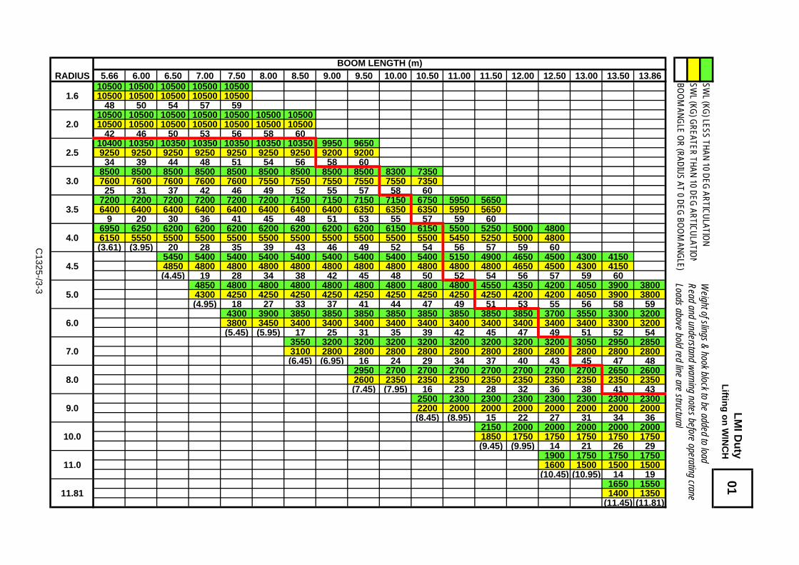
RADIUS 5.66 6.00 6.50 7.00 7.50 8.00 8.50 9.00 9.50 10.00 10.50 11.00 11.50 12.00 12.50 13.00 13.50 13.8610500 10500 10500 10500 10500
1.6 10500 10500 10500 10500 1050048 50 54 57 59
10500 10500 10500 10500 10500 10500 105002.0 10500 10500 10500 10500 10500 10500 10500
42 46 50 53 56 58 6010400 10350 10350 10350 10350 10350 10350 9950 9650
2.5 9250 9250 9250 9250 9250 9250 9250 9200 920034 39 44 48 51 54 56 58 60
8500 8500 8500 8500 8500 8500 8500 8500 8500 8300 73503.0 7600 7600 7600 7600 7600 7550 7550 7550 7550 7550 7350
25 31 37 42 46 49 52 55 57 58 607200 7200 7200 7200 7200 7200 7150 7150 7150 7150 6750 5950 5650
3.5 6400 6400 6400 6400 6400 6400 6400 6400 6350 6350 6350 5950 56509 20 30 36 41 45 48 51 53 55 57 59 60
6950 6250 6200 6200 6200 6200 6200 6200 6200 6150 6150 5500 5250 5000 48004.0 6150 5550 5500 5500 5500 5500 5500 5500 5500 5500 5500 5450 5250 5000 4800
(3.61) (3.95) 20 28 35 39 43 46 49 52 54 56 57 59 605450 5400 5400 5400 5400 5400 5400 5400 5400 5150 4900 4650 4500 4300 4150
4.5 4850 4800 4800 4800 4800 4800 4800 4800 4800 4800 4800 4650 4500 4300 4150(4.45) 19 28 34 38 42 45 48 50 52 54 56 57 59 60
4850 4800 4800 4800 4800 4800 4800 4800 4800 4550 4350 4200 4050 3900 38005.0 4300 4250 4250 4250 4250 4250 4250 4250 4250 4250 4200 4200 4050 3900 3800
(4.95) 18 27 33 37 41 44 47 49 51 53 55 56 58 594300 3900 3850 3850 3850 3850 3850 3850 3850 3850 3700 3550 3300 3200
6.0 3800 3450 3400 3400 3400 3400 3400 3400 3400 3400 3400 3400 3300 3200(5.45) (5.95) 17 25 31 35 39 42 45 47 49 51 52 54
3550 3200 3200 3200 3200 3200 3200 3200 3200 3050 2950 28507.0 3100 2800 2800 2800 2800 2800 2800 2800 2800 2800 2800 2800
(6.45) (6.95) 16 24 29 34 37 40 43 45 47 482950 2700 2700 2700 2700 2700 2700 2700 2650 2600
8.0 2600 2350 2350 2350 2350 2350 2350 2350 2350 2350(7.45) (7.95) 16 23 28 32 36 38 41 43
2500 2300 2300 2300 2300 2300 2300 23009.0 2200 2000 2000 2000 2000 2000 2000 2000
(8.45) (8.95) 15 22 27 31 34 362150 2000 2000 2000 2000 2000
10.0 1850 1750 1750 1750 1750 1750(9.45) (9.95) 14 21 26 29
1900 1750 1750 175011.0 1600 1500 1500 1500
(10.45) (10.95) 14 191650 1550
11.81 1400 1350(11.45) (11.81)
01 L
MI D
uty
Liftin
g o
n W
INC
HBOOM LENGTH (m)
C1325-/3-3
SWL (KG
) LESS THAN 10 DEG ARTICULATIO
NSW
L (KG) G
REATER THAN 10 DEG ARTICULATIO
NW
eight of slings & hook block to be added to load Read and understand warning notes before operating crane Loads above bold red line are structural
BOO
M ANG
LE OR (RADIUS AT 0 DEG
BOO
M ANG
LE)

LMI Duty 03Lifting on WINCHMANUAL EXTENDED
SWL (KG) LESS THAN 10 DEG ARTICULATIONSWL (KG) GREATER THAN 10 DEG ARTICULATIONBOOM ANGLE
Weight of slings & hook block to be added to load Read and understand warning notes before operating craneLoads above bold red line are structural
MANUAL EXT'NMAX LENGTH 17.91
MAX SWLRADIUS 1850
6.72 185060
16009.29 1600
501300
11.53 130040
115013.35 1150
301050
14.70 105020
105015.54 950
101050
15.86 9500
NOTE :17.9m Boom length includes Manual 3rd extension.Ratings for Manual extension are structural & basedon Boom Angle, not radius. The ratings do notchange if the power sections are retracted with themanual extended.
C1325-/3-4

BOOM LENGTH (m)RADIUS 5.95 6.50 7.00 7.50 8.00 8.50 9.00 9.50 10.00 10.50 11.00 11.50 12.00 12.50 13.00 13.50 14.00 14.15
8000 8000 8000 80001.6 8000 8000 8000 8000
50 54 57 598000 8000 8000 8000 8000 8000
2.0 8000 8000 8000 8000 8000 800045 50 53 56 58 60
8000 8000 8000 8000 8000 8000 8000 80002.5 8000 8000 8000 8000 8000 8000 8000 8000
38 44 48 51 54 56 58 607750 8000 8000 8000 8000 8000 8000 8000 8000 7950
3.0 7650 7650 7650 7650 7600 7600 7600 7600 7600 760030 37 42 46 49 52 55 57 59 60
7250 7250 7250 7250 7200 7200 7200 7200 7200 7200 6300 57003.5 6450 6450 6450 6450 6450 6450 6400 6400 6400 6400 6300 5700
19 30 36 41 45 48 51 53 55 57 59 606400 6250 6250 6250 6250 6250 6200 6200 6200 6200 5850 5300 5050 4850
4.0 5700 5550 5550 5550 5550 5550 5550 5500 5500 5500 5500 5300 5050 4850(3.90) 20 29 35 39 43 46 49 52 54 56 57 59 60
5500 5450 5450 5450 5450 5450 5450 5450 5450 5450 4950 4700 4550 4350 42004.5 4900 4850 4850 4850 4850 4850 4850 4800 4800 4800 4800 4700 4550 4350 4200
(4.45) 19 28 34 38 42 45 48 50 52 54 56 57 59 604900 4850 4850 4850 4850 4850 4800 4800 4800 4600 4400 4250 4100 3950 3800 3750
5.0 4300 4300 4300 4300 4300 4250 4250 4250 4250 4250 4250 4250 4100 3950 3800 3750(4.95) 19 27 33 37 41 44 47 49 51 53 55 56 58 59 59
4350 3950 3900 3900 3900 3900 3900 3900 3900 3900 3750 3600 3500 3200 32006.0 3850 3450 3450 3450 3450 3450 3450 3450 3400 3400 3400 3400 3400 3200 3200
(5.45) (5.95) 17 25 31 35 39 42 45 47 49 51 53 54 553550 3250 3250 3250 3250 3250 3250 3200 3200 3100 3000 2900 2850
7.0 3150 2850 2850 2850 2850 2850 2850 2850 2800 2800 2800 2800 2800(6.45) (6.95) 17 24 29 34 37 40 43 45 47 49 49
3000 2750 2750 2750 2750 2750 2700 2700 2700 2600 25508.0 2600 2400 2400 2400 2400 2400 2400 2400 2350 2350 2350
(7.45) (7.95) 16 23 28 32 36 38 41 43 442550 2350 2350 2350 2350 2350 2350 2350 2350
9.0 2200 2050 2050 2050 2050 2050 2050 2050 2050(8.45) (8.95) 15 22 27 31 34 37 38
2200 2050 2050 2050 2050 2000 200010.0 1900 1750 1750 1750 1750 1750 1750
(9.45) (9.95) 15 21 26 30 311900 1800 1750 1750 1750
11.0 1650 1500 1500 1500 1500(10.45) (10.95) 14 20 22
1650 1550 155012.00 1400 1350 1300
(11.45) (11.95) (12.00)
02
Weight of slings & hook block to be added to load
Read and understand warning notes before operating crane Loads above bold red line are structural
NO
TE
: Wh
en u
sing
the rh
ino
ho
ok, en
sure th
e win
ch ro
pe is fu
lly tensio
ned
.
C1325-/3-5
BOO
M ANG
LE OR (RADIUS AT 0 DEG
BOO
M ANG
LE)SW
L (KG) G
REATER THAN 10 DEG ARTICULATIO
NSW
L (KG) LESS THAN 10 DEG
ARTICULATION
LM
I Du
ty L
ifting
on
RH
INO
HO
OK

LMI Duty 04Lifting on RHINO HOOKMANUAL EXTENDED
SWL (KG) LESS THAN 10 DEG ARTICULATIONSWL (KG) GREATER THAN 10 DEG ARTICULATIONBOOM ANGLE
Weight of slings & hook block to be added to load Read and understand warning notes before operating craneLoads above bold red line are structural
MANUAL EXT'NMAX LENGTH 18.20
MAX SWLRADIUS 1750
7.01 175060
15009.58 1500
501200
11.82 120040
105013.64 1050
301000
14.99 100020
100015.83 950
101000
16.15 9000
NOTE :18.2m Boom length includes Manual 3rd extension.Ratings for Manual extension are structural & basedon Boom Angle, not radius. The ratings do notchange if the power sections are retracted with themanual extended.
C1325-/3-6

LMI Duty 05Lifting on FLYJIBMANUAL RETRACTED
FLYJIBMAX LENGTH 16.46
MAX SWLRADIUS 750 SWL (KG) LESS THAN 10 DEG ARTICULATION
6.04 750 SWL (KG) GREATER THAN 10 DEG ARTICULATION60 BOOM ANGLE700
8.40 70050650 Weight of slings & hook block to be added to load
10.44 650 Read and understand warning notes before40 operating crane600 Loads above bold red line are structural
12.11 60030550
13.35 550 NOTE :20 16.46m Boom length includes Flyjib.500 Ratings for Flyjib are structural & based
14.13 500 on Boom Angle, not radius. The ratings do not10 change if the power sections are retracted with500 the Flyjib installed.
14.41 5000
LMI Duty 06Lifting on FLYJIBMANUAL EXTENDED
MANUAL EXT'NMAX LENGTH 20.51 Vertical offset from pivot to centre of sheave
MAX SWLRADIUS 750 SWL (KG) LESS THAN 10 DEG ARTICULATION
8.07 750 SWL (KG) GREATER THAN 10 DEG ARTICULATION60 BOOM ANGLE700
11.00 70050650 Weight of slings & hook block to be added to load
13.54 650 Read and understand warning notes before40 operating crane600 Loads above bold red line are structural
15.62 60030550
17.15 550 NOTE :20 20.51m Boom length includes Manual 3rd extension500 & Flyjib. Ratings for Flyjib are structural & based
18.11 500 on Boom Angle, not radius. The ratings do not10 change if the power sections are retracted with500 the manual extended.
18.46 5000
C1325-/3-7

LMI Duty 10Lifting on INNER LUG
Weight of slings & hook block to be added to load Read and understand warning notes before operating craneLoads above bold red line are structural
SWL (KG) LESS THAN 10 DEG ARTICULATIONSWL (KG) GREATER THAN 10 DEG ARTICULATIONBOOM ANGLE OR (RADIUS AT 0 DEG BOOM ANGLE)
BOOM LENGTH (m)RADIUS 3.65 4.00 4.50 5.00 5.50 6.00 6.50 7.00 7.75
15000 15000 15000 14500 13650 12550 11700 112001.6 13900 13950 13850 13800 13650 12550 11700 11200
(1.60) 24 36 43 48 53 56 5912550 12250 12200 12150 11500 10700 10250 9700
2.0 11150 10850 10800 10750 10700 10650 10250 9700(1.95) 26 36 43 48 51 55 59
9700 9500 9450 9400 9350 9250 87502.5 8550 8350 8350 8300 8250 8250 8200
(2.45) 25 34 41 46 49 547800 7650 7600 7600 7550 7550
3.0 6850 6700 6700 6650 6650 6600(2.95) 23 33 39 44 49
6450 6350 6300 6300 62503.5 5650 5550 5500 5500 5450
(3.45) 22 31 38 445400 5350 5350 5300
4.0 4700 4650 4650 4600(3.95) 22 30 39
4650 4600 45504.5 4000 3950 3950
(4.45) 21 324000 3950
5.0 3450 3400(4.95) 25
34505.5 2950
133300
5.7 2800(5.70)
C1325-/3-8

LMI Duty 11Lifting on OUTER LUG
Weight of slings & hook block to be added to load Read and understand warning notes before operating craneLoads above bold red line are structural
SWL (KG) LESS THAN 10 DEG ARTICULATIONSWL (KG) GREATER THAN 10 DEG ARTICULATIONBOOM ANGLE OR (RADIUS AT 0 DEG BOOM ANGLE)
BOOM LENGTH (m)RADIUS 4.70 5.00 5.50 6.00 6.50 7.00 7.50 8.00 8.80
15000 15000 14650 14000 13050 119001.6 14650 14550 14400 14000 13050 11900
39 43 48 53 56 5912900 12850 12700 12600 12000 10900 10150
2.0 11500 11450 11350 11250 11150 10900 1015031 36 43 48 51 55 57
10100 10050 9950 9900 9800 9750 9200 8850 77002.5 9000 8950 8850 8800 8700 8650 8600 8550 7700
15 25 34 41 46 49 53 55 599450 8350 8150 8050 8000 7950 7900 7850 7050
3.0 8400 7400 7200 7150 7100 7000 6950 6950 6850(2.65) (2.95) 23 33 39 44 48 51 55
6900 6750 6700 6650 6600 6550 65003.5 6100 5950 5900 5850 5800 5800 5700
(3.45) 22 31 38 42 46 515850 5700 5700 5650 5600 5550
4.0 5150 5050 5000 4950 4900 4850(3.95) 22 30 36 41 47
5000 4900 4900 4850 48004.5 4400 4300 4250 4250 4200
(4.45) 21 29 35 424350 4250 4250 4200
5.0 3800 3700 3700 3650(4.95) 20 28 37
3800 3750 37005.5 3300 3250 3200
(5.45) 19 313350 3300
6.0 2900 2850(5.95) 24
29506.5 2500
142750
6.8 2350(6.75)
C1325-/3-9

LMI Duty 12Lifting in MANBASKET MANUAL RETRACTED
MAXIMUM MANBASKET SWL: 275 KG (SEE NOTE BELOW)BASKET WEIGHT: 225 KG
Read and understand warning notes beforeoperating crane
NOTE:
LMI Duty 13Lifting in MANBASKET
MANUAL EXTENDED
MANUAL EXT'NMAX LENGTH 17.91
MAX SWLRADIUS 275 SWL (KG) LESS THAN 10 DEG ARTICULATION
7.98 275 SWL (KG) GREATER THAN 10 DEG ARTICULATION60 BOOM ANGLE275
10.71 27550205
13.05 205 Read and understand warning notes before40 operating crane155 Loads above bold red line are structural
14.93 15530125
16.30 125 NOTE :20 17.91m Boom length includes Manual 3rd extension125 but not Manbasket. Ratings for Manbasket are structural &
17.11 90 based on Boom Angle, not radius. The ratings do not10 change if the power sections are retracted with125 the manual extended.
17.34 900
THE TOTAL WEIGHT OF THE MANBASKET PLUS MEN AND EQUIPMENT IS NOT TO EXCEED 1/3 OF THE SAFE WORKING LOAD AS READ ON LOAD CHART (LIFTING ON THE WINCH - DUTY 01) FOR THE BOOM LENGTH AND RADIUS BEING USED.
C1325-/3-10

C1325-/4-1
SECTION 4
CRANE DATA
MACHINE DIMENSIONS
HYDRAULIC DATA

C1325-/4-2
INFORMATIONAL DATA
Crane DimensionsLength (carrier) 5 925Width 2 500Height (with Boom) 2 950Length Overall 9 010Wheelbase 3 800Front Axle Weight 6 000 kgRear Axle Weight 10 000 kg

C1325-/4-3
HYDRAULIC DATA
MACHINE IS DESIGNED TO OPERATE AT THESEMAXIMUM PRESSURES.
FUNCTIONPUMP
STANDBYPRESSURE
PUMPPRESSURECOMPEN-
SATOR
STEERINGRELIEF
TELE PORTRELIEF
SETTING(BAR) 24 210 175 170
TESTPOINT G1 G1 G2 G1
HYDRAULIC OIL TEMPERATURE MUST BE BETWEEN PLUS 20°C AND40°C WHEN SETTING ABOVE PRESSURES.
PRESSURES TO BE CHECKED AT 1000 RPM – STANDBY PRESSURECAN BE CHECKED AT IDLE.
DO NOT HOLD ON RELIEF MORE THAN 10 SECONDS TO AVOIDOVERHEATING THE OIL AND HYDRAULIC COMPONENT DAMAGE.
UNAUTHORISED PRESSURE SETTINGS IN EXCESS OF THE ABOVEVALUES WILL RESULT IN DENIAL OF WARRANTY CLAIMS.
PRESSURES TO BE WITHIN 5 BAR OF THE ABOVE VALUES.


