Hybrid Indoor Geolocation for Robotic · PDF fileHybrid Indoor Geolocation for Robotic...
195
1 | Page Hybrid Indoor Geolocation for Robotic Applications A Major Qualifying Project Report Submitted to the faculty of Worcester Polytechnic Institute In partial fulfillment of the requirements for the Degree of Bachelor of Science By Yuan Shi Billy Zhong Ramsey Abouzahra Cengiz Karakoyunlu On 29 th April 2010
Transcript of Hybrid Indoor Geolocation for Robotic · PDF fileHybrid Indoor Geolocation for Robotic...

1 | P a g e
Hybrid Indoor Geolocation
for Robotic Applications
A Major Qualifying Project Report
Submitted to the faculty of
Worcester Polytechnic Institute
In partial fulfillment of the requirements for the
Degree of Bachelor of Science
By
Yuan Shi
Billy Zhong
Ramsey Abouzahra
Cengiz Karakoyunlu
On 29th
April 2010
2 | P a g e
Table of Contents ABSTRACT .................................................................................................................................... 7
CHAPTER I – INTRODUCTION .................................................................................................. 8
1.1 Motivation ............................................................................................................................. 9
1.2 Previous Work .................................................................................................................... 10
1.3 Project Description.............................................................................................................. 12
1.4 Project Outline .................................................................................................................... 14
CHAPTER II – Analysis of Sensor Behaviors ............................................................................. 15
2.1 Sensing the RSS of Wi-Fi ................................................................................................... 15
2.2 Inertial Measurement Unit for Angle Tracking .................................................................. 17
2.2.1 Gyroscope for Sensing Angular Velocity .................................................................... 18
2.2.3 Magnetometer for Sensing Initial Heading .................................................................. 20
2.3 Odometer for sensing velocity ............................................................................................ 22
2.4 Ultrasound Sensors for Correcting Heading ....................................................................... 23
CHAPTER III – LOCATION AND TRACKING ALGORITHMS ............................................ 27
3.1 Kernel Method for Wi-Fi Localization ............................................................................... 28
3.2 Extended Kalman Filter for Sensor Fusion ......................................................................... 30
3.2.1 Initialization Process .................................................................................................... 31
3.2.2 Time Update Process ................................................................................................... 32
3.2.3 Measurement Update Stage ......................................................................................... 33
CHAPTER IV – SOFTWARE DESIGN AND INTEGRATION ................................................ 35
4.1 Overview of Project Architecture ....................................................................................... 35
4.2 JAVA Client Interface ........................................................................................................ 36
4.3 Robot Location Sensor Server ............................................................................................ 38
CHAPTER V – PERFORMANCE ANALYSIS .......................................................................... 42
5.1 Generating Ground Truth for Reference ............................................................................. 42
5.2 Performance of the Dead Reckoning Algorithm ................................................................ 44
5.3 Performance of Wi-Fi Localization Algorithm ................................................................... 47
5.4 Performance using the Extended Kalman Filter for Fusion ................................................ 51
5.5 Comparative Performance Analysis ................................................................................... 54
CHAPTER VI CONCLUSION .................................................................................................... 56
Future Work .............................................................................................................................. 57
Acknowledgements ................................................................................................................... 58
APPENDICES .............................................................................................................................. 59

3 | P a g e
Appendix A – ER-1 Position & Velocity Measurements (10, 15, 25, 50 in.) .......................... 59
Appendix B – Wi-Fi Localization Flow Chart ......................................................................... 63
Appendix C – sonar.c (Code that is developed for Vex Ultrasonic Rangefinder) .................... 64
Appendix D- Laser-Optical-Line Tracker Sensors ................................................................... 66
Appendix E – Kalman Filter ..................................................................................................... 75
Appendix F – Wi-Fi Kalman Filter Results .............................................................................. 78
Appendix G – Wi-Fi Kernel Method MATLAB Codes ........................................................... 79
Appendix H – EKF Time Update MATLAB Codes ................................................................ 81
Appendix I – EKF Measurement Update MATLAB Codes ..................................................... 82
Appendix J – EKF Initialization MATLAB Codes .................................................................. 83
Appendix K – Angle Clip MATLAB Codes ............................................................................ 84
Appendix L – Ground Truth MATLAB Codes ........................................................................ 85
Appendix M – Get IMU Data MATLAB Codes ...................................................................... 87
Appendix N – Ground Truth C# Code ...................................................................................... 88
Appendix O.1: Robot Remote Control Client (ER1Navigator) Models ................................... 89
Appendix O.1.1: Robot.java .............................................................................................. 89
Appendix O.1.2: Map.java ................................................................................................ 91
Appendix O.1.3: ER1RemoteConnection.java ................................................................. 94
Appendix O.2: Robot Remote Control Client (ER1Navigator) Controllers ............................. 95
Appendix O.2.1: ER1NavigatorFrame.java ...................................................................... 95
Appendix O.2.2: ER1Controller.java ................................................................................ 97
Appendix O.2.3: MapController.java ................................................................................ 98
Appendix O.2.4: MoveController.java .............................................................................. 99
Appendix O.2.5: RobotLocationController.java ............................................................. 104
Appendix O.2.6: LoggerController.java ......................................................................... 105
Appendix O.3: Robot Remote Control Client (ER1Navigator) Views................................... 107
Appendix O.3.1: CameraPanel.java ................................................................................ 107
Appendix O.3.2: CommandPanel.java ............................................................................ 109
Appendix O.3.3: ConnectionPanel.java .......................................................................... 110
Appendix O.3.4: ControlPanel.java ................................................................................ 112
Appendix O.3.5: LoggerPanel.java ................................................................................. 114
Appendix O.3.6: MapPanel.java ..................................................................................... 117
Appendix O.3.7: MapView.java ..................................................................................... 120
Appendix O.3.8: RobotView.java ................................................................................... 121
4 | P a g e
Appendix P.1: Robot Server Models ...................................................................................... 123
Appendix P.1.1: SensorData.cs ....................................................................................... 123
Appendix P.1.2: EKFState.cs .......................................................................................... 124
Appendix P.1.3: ER1Position.cs ..................................................................................... 128
Appendix P.1.4: IMUData.cs .......................................................................................... 131
Appendix P.1.5: WiFiData.cs .......................................................................................... 133
Appendix P.1.6: SonarData.cs......................................................................................... 136
Appendix P.2: Robot Server Controllers ................................................................................ 138
Appendix P.2.1: SensorController.cs ............................................................................... 138
Appendix P.2.2: ER1Controller.cs ................................................................................... 141
Appendix P.2.3: IMUController.cs .................................................................................. 148
Appendix P.2.4: WiFiController.cs .................................................................................. 152
Appendix P.2.5: SonarController.cs ................................................................................. 157
Appendix P.2.6: WiFiDB.cs ............................................................................................. 161
Appendix P.2.7: EKFAlgorithmClass.cs ......................................................................... 163
Appendix P.2.8: RemoteCommunicator.cs ...................................................................... 171
Appendix P.2.9: Form1.cs ................................................................................................ 179
BIBLIOGRAPHY ....................................................................................................................... 194
5 | P a g e
Table of Figures Figure 1: Indoor robotic applications requiring location awareness .............................................. 9
Figure 2: General concept of the multi-sensor location aware robot with real-time remote control
and map display ............................................................................................................................ 12 Figure 3: Overview of the system architecture illustrating the sensor integration as well as the
remote control, video stream, map display, and two way communications ................................. 13 Figure 4: Database for applying the Kernel method algorithm for wi-fi position estimate ......... 16
Figure 5: Overview of the inertial measurement unit and its tracking coordinates ..................... 17 Figure 6: Inertial measurement unit data log format ................................................................... 18 Figure 7: Gyroscope readings of right turn made around the third floor of Atwater Kent
Laboratory ..................................................................................................................................... 19 Figure 8: Gyroscope readings of left turn made around the third floor of Atwater Kent ............. 19
Figure 9: Heading tracking of magnetometer .............................................................................. 21 Figure 10: Ultrasonic rangefinder kit for correcting the heading ................................................ 25
Figure 11: Overall description of the algorithms with an outline of the individual sampling
frequencies of each sensor as well as the post processing engine ................................................ 27 Figure 12: Diagram for constructing the database and computing the sum of squared errors for
each sample and location using the received signal strength readings ......................................... 28
Figure 13: Creating and normalizing the Kernel for probability estimate .................................... 29 Figure 14: Calculating the probability of the robot in each location using the Kernel ................ 29
Figure 15: Overview of the processes involved in the Extended Kalman Filter algorithm ......... 30 Figure 16 : Architecture overview identifying the sensors as well as the server to client platform
with real time remote control, video stream, and map display ..................................................... 35
Figure 17: Robot client side of the architecture with remote control, video stream, and
location/map display ..................................................................................................................... 36
Figure 18: Client interface with the video stream on the upper right, control system on the lower
right, and the map/location display on the left .............................................................................. 38
Figure 19: Robot server side of the architecture responsible for sampling the different sensors
and applying the fusion algorithm on the sensors ......................................................................... 39 Figure 20: Robot location server interface showing the different sensors................................... 40
Figure 21: Robot location server showing the different algorithms ............................................ 41 Figure 22: Ground truth application for logging the actual position of the robot with time ........ 43
Figure 23: Performance of the dead reckoning algorithm, green vs. ground truth, purple .......... 45 Figure 24: Timing error analysis of the dead reckoning algorithm ............................................. 46 Figure 25: Cumulative density function of the dead reckoning algorithm .................................. 47
Figure 26: Performance of the wi-fi localization algorithm, red vs. ground truth, blue .............. 48 Figure 27: Timing error analysis of the wi-fi localization algorithm .......................................... 49
Figure 28: Cumulative density function of the wi-fi localization algorithm ............................... 50 Figure 29: Performance of the Extended Kalman Filter algorithm, blue vs. ground truth, black 51
Figure 30: Timing error analysis of the Extended Kalman Filter Algorithm .............................. 52 Figure 31: Cumulative density function of the Extended Kalman Filter ..................................... 53 Figure 32: Timing error analysis of the algorithms: Extended Kalman Filter, wi-fi localization,
and dead reckoning ....................................................................................................................... 54 Figure 33: Cumulative density function of the three algorithms: extended Kalman filter, wi-fi
localization, and dead reckoning................................................................................................... 55 Figure 34: Computer Velocity vs. Measured Velocity ................................................................ 61
6 | P a g e
Figure 35: Drift comparison for five different cases ................................................................... 62
Figure 36: Wi-Fi Flow Chart ........................................................................................................ 63 Figure 37: Vex Line Tracker Sensor ............................................................................................ 69 Figure 38: Laser Readings and Ultrasonic Sensor Readings ....................................................... 71
Figure 39: Laser vs. Ultrasonic Sensor Readings ........................................................................ 72 Figure 40: Vex Ultrasound Sensor mounted to four different sides on the robot ........................ 73 Figure 41: Kalman Filter Model ................................................................................................... 75 Figure 42: Kalman Filter Results .................................................................................................. 77 Figure 43: Raw Wi-Fi (Red) vs. KF Wi-Fi (Black) Results ........................................................ 78
7 | P a g e
ABSTRACT
The purpose of our major qualifying project is to develop a localization method for
precise indoor geolocation. There are two phases in our project. The first involves devising an
algorithm to combine the readings from four different sensors, a gyroscope, odometer,
ultrasound sensors, and Wi-Fi Received Signal Strength readings. Under this phase, we designed
and implemented a fusion algorithm to incorporate these various sensors to take advantage of
their individual tracking abilities. In the terms of integrating the local sensors, we have
successfully incorporated the gyroscope, and odometer to the fusion algorithm, but the
ultrasound sensors have yet been integrated. The second phase involves developing the
application and user interface of our project. We developed a user-friendly interface that allows
for real time remote control, map display, and algorithm evaluation; this allows for real time
applications and performance analysis. The user interface is written in JAVA, while the server
used to combine the readings from the sensors is written in C#. Finally, the scripts used to
render the readings from each individual sensor are written in MATLAB, and C.
By combining the readings from these various sensors using the Extended Kalman Filter,
an optimal position estimate can be achieved. The position estimates of the local sensors
(gyroscope, odometer, and ultrasound sensors) are accurate only in the short term, because it is
subjected to cumulative drift. On the other hand, Wi-Fi localization is accurate in the long term
by taking advantage of an existing RF infrastructure, but is slow responsive to instantaneous
variations. However, using our sensor fusion algorithm to combine the inertial system and Wi-Fi
localization, the advantages of each can be exploited to achieve optimal results.

8 | P a g e
CHAPTER I – INTRODUCTION
Precise localization techniques have been the interest of study for decades. Until recently,
Global Positioning System (GPS) has been developed and widely used in commercial
applications. However, its performance in indoor area is significantly deteriorated due to path
loss and other signal degenerating agents. Due to the inaccuracy of GPS in indoor applications,
there is an increasing demand for precise localization inside buildings. Wi-Fi based localization
technology makes use of Received Signal Strength (RSS) to determine the position of an object
inside a building. One of the advantages of Wi-Fi localization is that it uses an existing
infrastructure, which makes it an inexpensive sensor with extremely low power consumption.
Lastly, since it is also a software-based sensor, it is far easier to debug, test, and modify as
opposed to hardware-based sensors.
With the emergence of the Global Positioning System, it has always been a technological
interest to precisely locate the position of objects. Many large corporations today apply these
localization methods into commercial applications such as portable GPS car navigation systems
by TomTom, or handheld GPS devices for hiking by Garmin. However, due to the inability to
identify obstacles inside buildings, GPS navigation is only effective in outdoor applications.
Hence, many engineers today are currently working on different systems for indoor localization.
Methods such as Wi-Fi localization was designed for this purpose. Algorithms based on these
techniques use signal features, such as Time of Arrival (TOA), Angle of Arrival (AOA), and
Received Signal Strength (RSS) to estimate an object‟s location. However, due to the inaccuracy
of Wi-Fi localization, other sensors must be incorporated to compensate for the error. In recent
years, an Inertial Measurement Unit (IMU) and other sensors are integrated with Wi-Fi to
9 | P a g e
provide better indoor position estimates. Hence, the topic of our Major Qualifying Project is to
design an effective indoor geolocation scheme for robotic applications based on the fusion of
Wi-Fi localization, inertial sensors and rangefinder sensors.
1.1 Motivation
Traditionally, indoor localization algorithms were mainly developed for tracking people
and assets as described in [1]. However, with the emergence of robotics, more and more
applications involving automated tasks require precise localization of the robot. The main
motivation behind robotic indoor localization is that such an application allows robots to be
location aware. With modern software techniques, a robot can be automated to perform certain
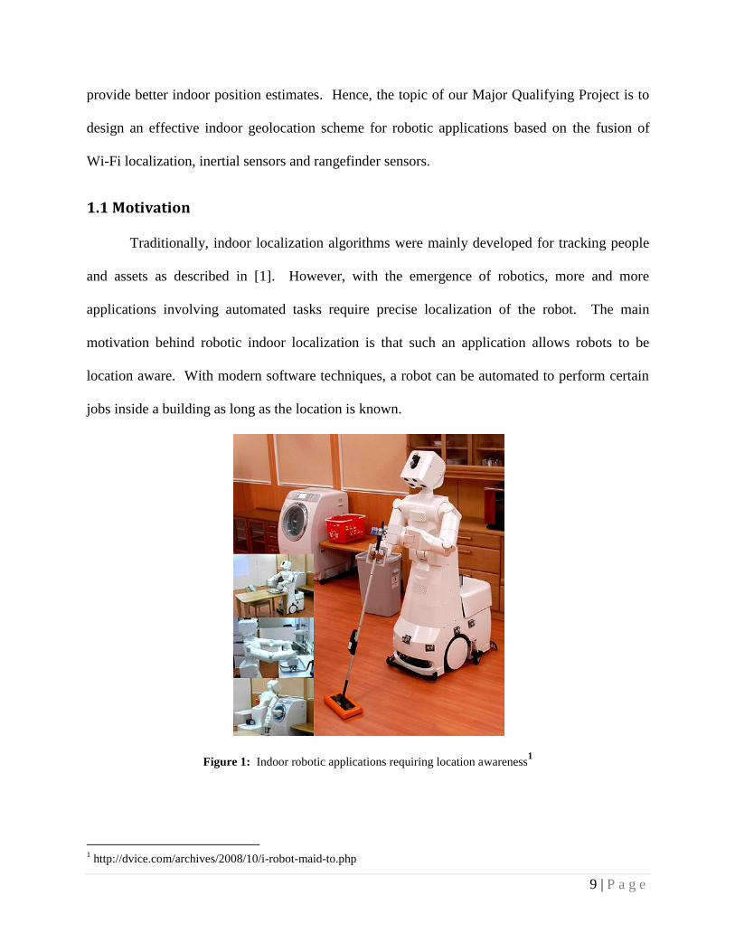
jobs inside a building as long as the location is known.
Figure 1: Indoor robotic applications requiring location awareness1
1 http://dvice.com/archives/2008/10/i-robot-maid-to.php
10 | P a g e
For example, a robot can serve as a maid similar to the one on the above figure, but this
would not be possible without knowing the exact location of the robot. In a sense, this new
notion of an automated task-performing robot is the evolution of Telepresence. Not only will
individuals be able to meet face-to-face, but they may also take advantage of the robot‟s
mechanic instruments to perform a variety of tasks. Other applications proposed in this field
include a tour guide system, where a robot can be used to give a tour in a museum and explain
certain artifacts and artworks along the way [2].
However, due to the fact that GPS is completely inaccurate in indoor environments, more
and more research has been conducted on hybrid localization techniques. Our Major Qualifying
Project focuses on the design and implementation of a location aware multi-sensor robotic
platform for indoor applications by taking advantage of existing Wi-Fi infrastructure. In terms
of current technology, the integration of multiple sensors to precisely track the movement of an
object in an indoor environment is a new and evolving technology. Not only will our project
build on existing localization methods such as Wi-Fi; but more importantly it offers a new
approach and a different application to improve the existing localization technology further.
1.2 Previous Work
In the past few years, Wi-Fi localization has been studied in indoor location systems.
However, Wi-Fi alone does not provide the accuracy good enough to locate an object due to two
main flaws. The first is that Wi-Fi localization has shown that it‟s slow responsive to
instantaneous change. Furthermore it is also subjected to short term variations. An IMU is used
in this case, to correct the readings of the Wi-Fi for indoor applications.
In the study of Frank, Krach, Catterall and Robertson [3], the IMU has provided an
improved performance of determining the position of the robot. However, all the sensors
11 | P a g e
integrated in the IMU possess a certain amount of drift. Thus, its performance is dependent on
time and it starts to deteriorate as time increases. While the odometer is good at providing linear
velocity, its estimation of angular motion is not quite good. Thus, the odometer should be
compensated by other sensors to provide motion tracking of the object. In the recent years, many
different algorithms that are used to combine the readings of various sensors have been studied.
The particle filter is a sophisticated model estimation technique based on simulation [4]. Each
particle in the filter is heavily relied on the number of samples. When the number of sample is
large enough, the performance of a particle filter is better than the Extended Kalman Filter.
Extended Kalman Filter can be used to combine the readings from various sensors and to
display them on a map in real time by estimating the initial position and heading. The study of
Frank, Krach, Catterall and Robertson [3] proves that Extended Kalman Filter can be a very
useful method to track the indoor movement of a robot throughout a pre-defined path.
In order to have an idea about the accuracy of the Extended Kalman Filter (EKF) method
the Cumulative Distribution Function (CDF) can be used. In their study Frank, Krach, Catterall
and Robertson plotted the CDF of the Extended Kalman Filter method. The CDF method proves
that the probability of errors is much smaller when the Extended Kalman Filter method is
applied. Without EKF, the CDF results an average error of 3.2 meters; whereas with EKF the
average error is reduced to 1.6 meters. When there are not too many sample points, the Extended
Kalman Filter method is a very helpful method to combine the readings from external sensors
and to display the real time location of an object.
12 | P a g e
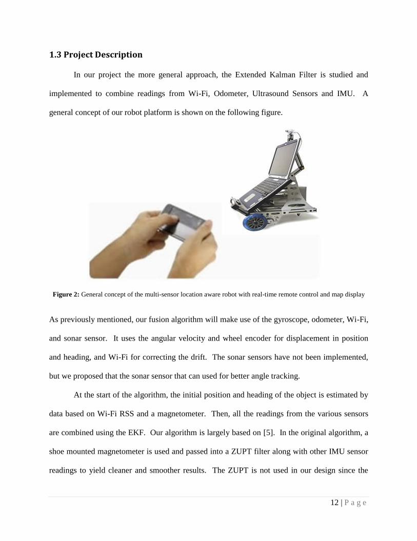
1.3 Project Description
In our project the more general approach, the Extended Kalman Filter is studied and
implemented to combine readings from Wi-Fi, Odometer, Ultrasound Sensors and IMU. A
general concept of our robot platform is shown on the following figure.
Figure 2: General concept of the multi-sensor location aware robot with real-time remote control and map display
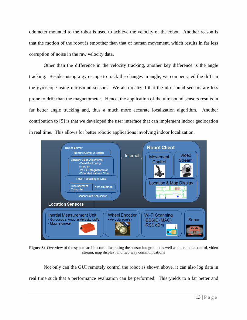
As previously mentioned, our fusion algorithm will make use of the gyroscope, odometer, Wi-Fi,
and sonar sensor. It uses the angular velocity and wheel encoder for displacement in position
and heading, and Wi-Fi for correcting the drift. The sonar sensors have not been implemented,
but we proposed that the sonar sensor that can used for better angle tracking.
At the start of the algorithm, the initial position and heading of the object is estimated by
data based on Wi-Fi RSS and a magnetometer. Then, all the readings from the various sensors
are combined using the EKF. Our algorithm is largely based on [5]. In the original algorithm, a
shoe mounted magnetometer is used and passed into a ZUPT filter along with other IMU sensor
readings to yield cleaner and smoother results. The ZUPT is not used in our design since the
13 | P a g e
odometer mounted to the robot is used to achieve the velocity of the robot. Another reason is
that the motion of the robot is smoother than that of human movement, which results in far less
corruption of noise in the raw velocity data.
Other than the difference in the velocity tracking, another key difference is the angle
tracking. Besides using a gyroscope to track the changes in angle, we compensated the drift in
the gyroscope using ultrasound sensors. We also realized that the ultrasound sensors are less
prone to drift than the magnetometer. Hence, the application of the ultrasound sensors results in
far better angle tracking and, thus a much more accurate localization algorithm. Another
contribution to [5] is that we developed the user interface that can implement indoor geolocation
in real time. This allows for better robotic applications involving indoor localization.
Figure 3: Overview of the system architecture illustrating the sensor integration as well as the remote control, video
stream, map display, and two way communications
Not only can the GUI remotely control the robot as shown above, it can also log data in
real time such that a performance evaluation can be performed. This yields to a far better and
14 | P a g e
more accurate analysis of the entire algorithm. Lastly, these evaluations also reveal the
dissimilarities between implementing an EKF in real time and simulating one based on data.
1.4 Project Outline
Chapter I is the introduction which gives the overview of our project, Hybrid Indoor
Geolocation for Robotic Applications. It discusses the motivation, and contribution of our
project. Chapter II provides an analysis of the behaviors of the sensors used in our project, such
as Wi-Fi, IMU, odometer from the ER-1 Robot and VEX Ultrasound sensor. Chapter III
explains the algorithms used to integrate the multiple sensors. For example, we used the Kernel
method to predict the position of the object based on RSS readings from Wi-Fi. It also describes
how the Extended Kalman Filter is implemented to combine the readings from all the sensors.
Chapter IV depicts the graphical user interface (GUI) that is designed to implement Extended
Kalman Filter in real time. Next, Chapter V analyzes the results from the experiments using the
system that is designed by our algorithm. It follows with a comparative performance analysis
which illustrates the pros and cons of each of the algorithms tested in our project. Lastly,
Chapter VI is the conclusion of the project, which also includes a brief discussion on the
remaining work that can be done in the future.

15 | P a g e
CHAPTER II – Analysis of Sensor Behaviors
After careful research and analysis, we decided to use Wi-Fi localization based on RSS,
MTx Inertial Measurement Unit, Evolution Robot 1 and lastly the optical sensors. Each one of
these sensors serves a specific function, making them all crucial in our localization method.
Thus, the purpose of the following subsections is to illustrate and explain the functions of each of
these sensors.
2.1 Sensing the RSS of Wi-Fi
Wi-Fi localization has gained much popularity over the recent years. Many indoor
localization applications have revolved around the notion of using received signal strength
measurements. Although there are methods to implement Wi-Fi localization using TOA, AOA,
and RSS, the most widely used algorithm involves using RSS. There are typically two basic Wi-
Fi localization techniques that are generally used in indoor localization. These two methods are
the nearest neighbor method and the kernel method, as suggested by [6].
The nearest neighbor method basically revolves around the notion of taking the
measurements of many points inside of a building, and by using the RSS of the access points
(AP), it estimates which point in the building the object is closest to simply by calculating the
distance as shown in [1]. The nearest neighbor method is efficient only if a large amount of data
samples are taken. Hence using the nearest neighbor method is sometimes unpractical [1].
The second method, Kernel method, is based on the idea of using a probability mass
function and the Gaussian curve to estimate the position of the object. From past results, the
Kernel method has proven to be more accurate and more practical than the nearest neighbor
method. Hence, our Wi-Fi localization technique will be largely based on the Kernel method
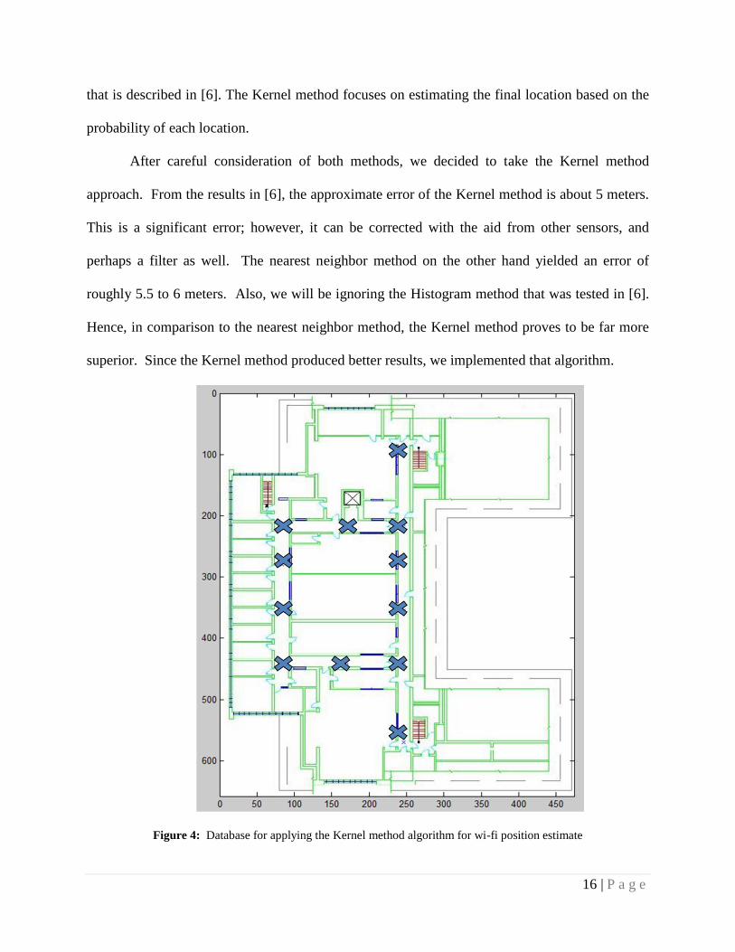
16 | P a g e
that is described in [6]. The Kernel method focuses on estimating the final location based on the
probability of each location.
After careful consideration of both methods, we decided to take the Kernel method
approach. From the results in [6], the approximate error of the Kernel method is about 5 meters.
This is a significant error; however, it can be corrected with the aid from other sensors, and
perhaps a filter as well. The nearest neighbor method on the other hand yielded an error of
roughly 5.5 to 6 meters. Also, we will be ignoring the Histogram method that was tested in [6].
Hence, in comparison to the nearest neighbor method, the Kernel method proves to be far more
superior. Since the Kernel method produced better results, we implemented that algorithm.
Figure 4: Database for applying the Kernel method algorithm for wi-fi position estimate
17 | P a g e
For the Kernel method, we have to first decide how many locations we want to train our
sample data. The purpose of this is to generate the database to compare the RSS readings. Only
with a well trained database will we be able to successfully compute the position estimate. As
shown from the above figure, we selected 12 locations in the route that our robot will navigate
across. At each of the 12 locations, we decided to take 24 training samples. The last variable in
the Kernel method is the number of access points. For the number of APs, we chose to use 54
different Mac Addresses. This is the total number of Mac addresses that we observed in the
entire building. With the parameters set for Wi-Fi, we moved on to analyzing the IMU.
2.2 Inertial Measurement Unit for Angle Tracking
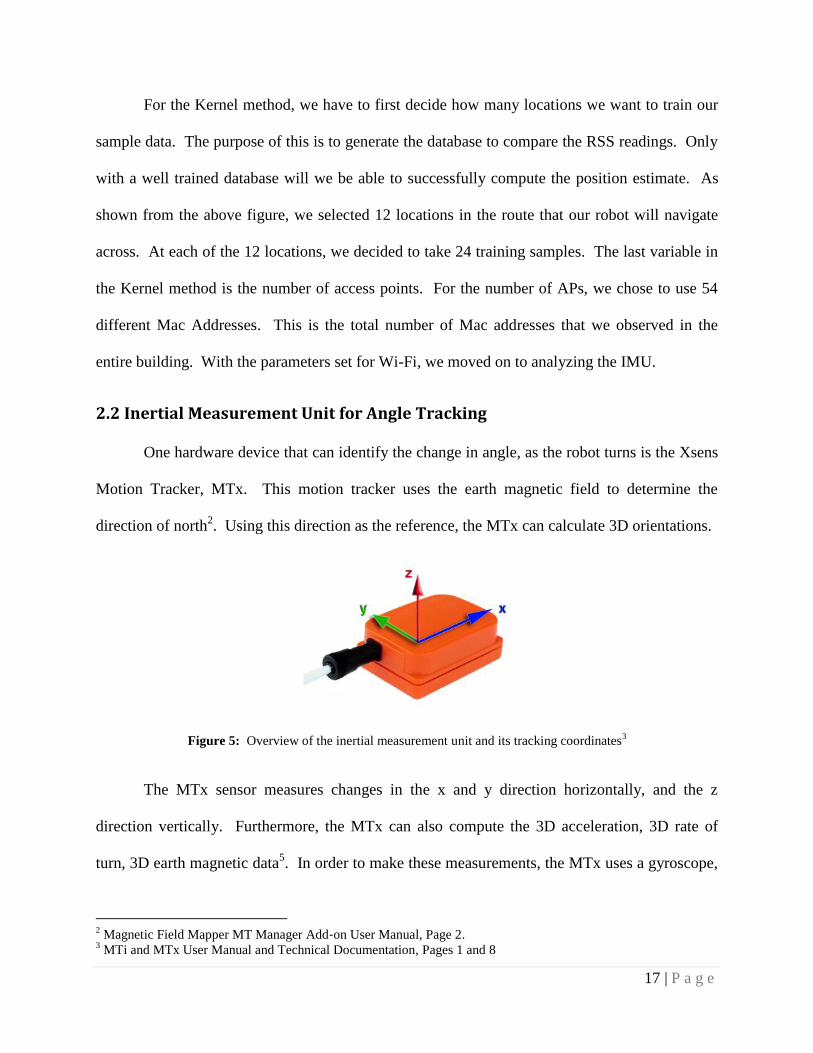
One hardware device that can identify the change in angle, as the robot turns is the Xsens
Motion Tracker, MTx. This motion tracker uses the earth magnetic field to determine the
direction of north2. Using this direction as the reference, the MTx can calculate 3D orientations.
Figure 5: Overview of the inertial measurement unit and its tracking coordinates3
The MTx sensor measures changes in the x and y direction horizontally, and the z
direction vertically. Furthermore, the MTx can also compute the 3D acceleration, 3D rate of
turn, 3D earth magnetic data5. In order to make these measurements, the MTx uses a gyroscope,
2 Magnetic Field Mapper MT Manager Add‐on User Manual, Page 2.
3 MTi and MTx User Manual and Technical Documentation, Pages 1 and 8

18 | P a g e
accelerometer and a magnetometer. The gyroscope is used for measuring the orientation, the
accelerometer for measuring the acceleration and the magnetometer for measuring the magnetic
field. Furthermore all the data read by the MTx can also be logged. The following figure
displays the types of data that the MTx sensor logs.
Figure 6: Inertial measurement unit data log format
4
From the above figure, it is clear that the MTx sensor measures acceleration, orientation
and the magnetic field in the X, Y, and Z directions with an accuracy of 4 bytes. However all
three measurement devices are prone to drift. One of the challenges of using is this MTx sensor
is to determine the behavior of the drift and develop a method to compensate for the drift. The
two components of the IMU that we will take advantage of are the angular velocity readings
from the gyroscope and the heading direction from the magnetometer.
2.2.1 Gyroscope for Sensing Angular Velocity
From the past work, we believe that the gyroscope readings would provide a better angle
measurement than the quaternion. However, in order to derive the angle readings using the
gyroscope, we have to integrate the gyroscope values. Note that the gyroscope output the rate of
turn in rad/s, so we have to integrate it. The next figure shows our results for the new values.
4 MTi and MTx User Manual and Technical Documentation, Pages 14 & 19.
19 | P a g e
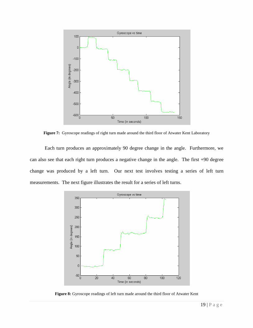
Figure 7: Gyroscope readings of right turn made around the third floor of Atwater Kent Laboratory
Each turn produces an approximately 90 degree change in the angle. Furthermore, we
can also see that each right turn produces a negative change in the angle. The first +90 degree
change was produced by a left turn. Our next test involves testing a series of left turn
measurements. The next figure illustrates the result for a series of left turns.
Figure 8: Gyroscope readings of left turn made around the third floor of Atwater Kent
20 | P a g e
Similar to the previous results, the above figure achieved an approximate +90 degree
change, which is exactly what we wanted. Since we have fixed the angle measurements of the
IMU, we can proceed to integrating the IMU and other sensors. Another note is that the angle
measurement has a small amount of drift which will be crucial if we let the drift build up. This is
one of the factors we considered while implementing the EKF.
2.2.3 Magnetometer for Sensing Initial Heading
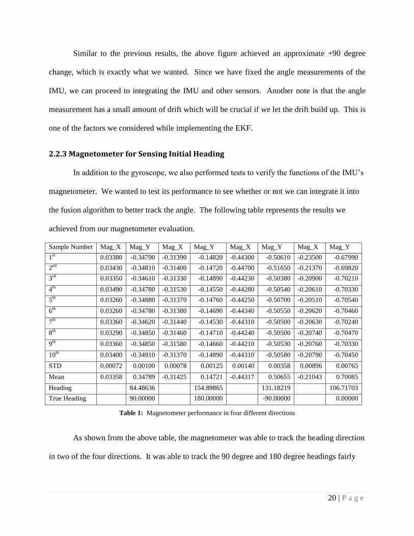
In addition to the gyroscope, we also performed tests to verify the functions of the IMU‟s
magnetometer. We wanted to test its performance to see whether or not we can integrate it into
the fusion algorithm to better track the angle. The following table represents the results we
achieved from our magnetometer evaluation.
Sample Number Mag_X Mag_Y Mag_X Mag_Y Mag_X Mag_Y Mag_X Mag_Y
1st 0.03380 -0.34790 -0.31390 -0.14820 -0.44300 -0.50610 -0.23500 -0.67990
2nd
0.03430 -0.34810 -0.31400 -0.14720 -0.44700 -0.51650 -0.21370 -0.69820
3rd
0.03350 -0.34610 -0.31330 -0.14890 -0.44230 -0.50380 -0.20900 -0.70210
4th
0.03490 -0.34780 -0.31530 -0.14550 -0.44280 -0.50540 -0.20610 -0.70330
5th
0.03260 -0.34880 -0.31370 -0.14760 -0.44250 -0.50700 -0.20510 -0.70540
6th
0.03260 -0.34780 -0.31380 -0.14690 -0.44340 -0.50550 -0.20620 -0.70460
7th
0.03360 -0.34620 -0.31440 -0.14530 -0.44310 -0.50500 -0.20630 -0.70240
8th
0.03290 -0.34850 -0.31460 -0.14710 -0.44240 -0.50500 -0.20740 -0.70470
9th
0.03360 -0.34850 -0.31580 -0.14660 -0.44210 -0.50530 -0.20760 -0.70330
10th 0.03400 -0.34910 -0.31370 -0.14890 -0.44310 -0.50580 -0.20790 -0.70450
STD 0.00072 0.00100 0.00078 0.00125 0.00140 0.00358 0.00896 0.00765
Mean 0.03358 0.34789 -0.31425 0.14721 -0.44317 0.50655 -0.21043 0.70085
Heading 84.48636 154.89865 131.18219 106.71703
True Heading 90.00000 180.00000 -90.00000 0.00000
Table 1: Magnetometer performance in four different directions
As shown from the above table, the magnetometer was able to track the heading direction
in two of the four directions. It was able to track the 90 degree and 180 degree headings fairly
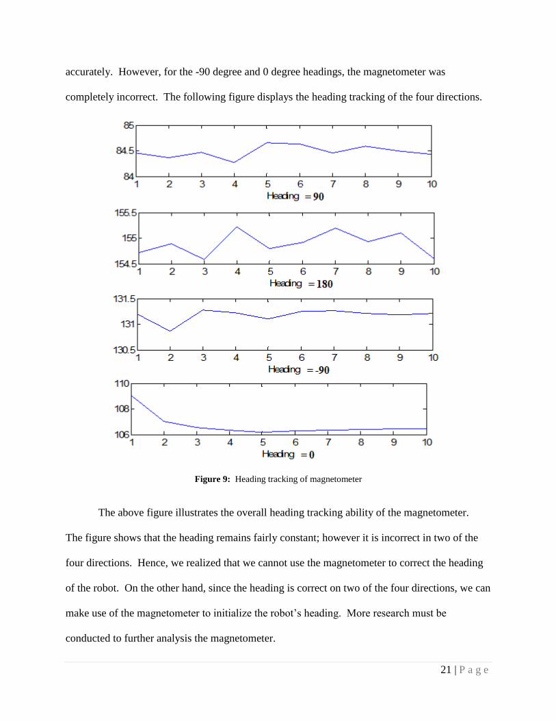
21 | P a g e
accurately. However, for the -90 degree and 0 degree headings, the magnetometer was
completely incorrect. The following figure displays the heading tracking of the four directions.
Figure 9: Heading tracking of magnetometer
The above figure illustrates the overall heading tracking ability of the magnetometer.
The figure shows that the heading remains fairly constant; however it is incorrect in two of the
four directions. Hence, we realized that we cannot use the magnetometer to correct the heading
of the robot. On the other hand, since the heading is correct on two of the four directions, we can
make use of the magnetometer to initialize the robot‟s heading. More research must be
conducted to further analysis the magnetometer.

22 | P a g e
2.3 Odometer for sensing velocity
In order to keep track of the robot‟s location, the user interface should display the
position and velocity readings accurately. The major problem with the movement of the robot is
the drifting problem. The robot itself has a built-in position sensor that transmits the robot‟s
coordinates to the user interface; but it is not possible to say that these readings are hundred
percent accurate since the robot is drifting while calculating its location.
The importance of accurate position reading is to provide the user the ability to control
the robot better. Without correct coordinates, the user would not know where the robot exactly is,
and this issue may cause the robot to hit the walls, metal structures, humans etc. In order to see
how the robot is actually moving, various data is collected from the movements of the robot
under different conditions.
The robot is tested in CWINS Lab. The user interface that we have developed through
JAVA allows us to give move and position commands to the robot. Sample syntax for the robot
to move 5 inches forward is;
move 5 i
The robot is instructed to travel five different distances: 5, 10, 15, 25 and 50 inches. The
reason to work on a variety of distances is to observe whether the amount of the drift changes
under different conditions. Besides the position reading; the velocity of the robot is also recorded
to check the consistency of the movement. To record the velocity, the time interval for each
movement is recorded at first. Then the distance that the robot travelled is recorded by both the
computer and by actually measuring it with measurement tool. The distance is divided by time to
obtain the velocity of the robot.
The robot is tested in CWINS Lab and it is instructed to move 5 inches forward.

23 | P a g e
Case1 cwins lab
measured(cm) comp(cm) measured velocity(cm/s) comp velocity(cm/s)
11.66 (10.5, 0.1) 5.83 5.25
11.2 (20.9, 0.1) 5.6 5.2
11.66 (31.2, 0.1) 5.83 5.15
10.97 (41.5, 0.1) 5.49 5.15
11.66 (51.9, 0.0) 5.83 5.2
10.82 (62.3, 0.0) 5.41 5.2
10.97 (72.8, 0.0) 5.49 5.25
10.82 (83.1, 0.0) 5.41 5.15
10.95 (93.6, 0.0) 5.43 5.25
11.66 (103.8, -0.1) 5.83 5.1
mean: 11.237 5.615 5.19
Table 2: Move 5 inches instruction test results for the robot
The table above shows the measured distance in the first column. Five inches is equal to
5* 2.54 = 12.7 centimeters. It is obvious that the robot is not travelling this distance. The column
“comp (cm)” indicates the position coordinates from the JAVA interface. The first coordinate is
x, and the second one is y coordinate. Dividing measured and computer indicated distance by
time, measured and comp velocity values are calculated.
The following four cases will be the measurement of the robot‟s movement under; 10, 15,
25 and 50 inches conditions. For each of those tables, the columns will be the same: Measured
(cm): Actual distance covered by robot measured by optical ruler, Comp (cm): The robot‟s
position coordinates from ER-1, Measured Velocity and Comp Velocity. These tables are
included in Appendix A.
2.4 Ultrasound Sensors for Correcting Heading
In order to obtain more accurate position and velocity data, the computer interface of the
ER-1 robot should be detecting the coordinates of the robot as correctly as possible. The usage of
24 | P a g e
sensors provides more data to the user interface; such that when the incoming data from IMU,
ER-1, Wi-Fi and the sensors is combined through an algorithm, the user of the robot interface
will know where the robot is exactly.
The integration of sensors into the robotics system is not a brand new research area.
There are researches concentrating on sensor integration into robotic systems, and one of them is
SLAM for Dummies (Riisgaard, Blas) [7]. SLAM means Simultaneous Localization and
Mapping. The purpose of the paper is to give a full tutorial about SLAM field. Throughout the
tutorial the integration of an optical sensor into an ER-1 robot is explained in details. This
particular paper would become fairly useful for our Indoor Localization Project since we are also
working on to integrate sensors into an ER-1 robot and to increase the accuracy of positioning.
Low Cost Optical Indoor Localization for Mobile Objects without Image Processing
(Salomon, Schneider, Wehden) [8] is another paper that concentrates on integrating sensors into
robotics systems. The purpose of the paper is to explain the weaknesses and disadvantages of
GPS systems when they are used indoors. GPS systems perform limited performance and they
induce costs that are far from being acceptable when they are used indoors. The study in this
paper basically tries to integrate an optical device into mobile objects to increase the localization
precision.
Following the studies and results of the researches above, we can perform the task of
integrating a sensor into an ER-1 robot to increase efficiency of the robot. As a result of
integration the cost of performance will be also decreased.
The Vex Ultrasonic Kit should be programmed at first in order to use it with robot
hardware. The required software for programming the Vex kit is EasyC Pro and IFI Loader. IFI
Loader is available online for free; but EasyC Pro asks $100 for installation. EasyC Pro is also
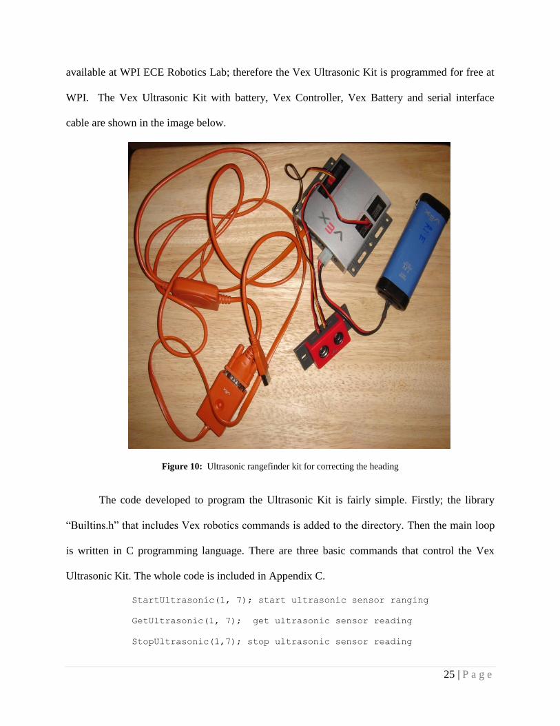
25 | P a g e
available at WPI ECE Robotics Lab; therefore the Vex Ultrasonic Kit is programmed for free at
WPI. The Vex Ultrasonic Kit with battery, Vex Controller, Vex Battery and serial interface
cable are shown in the image below.
Figure 10: Ultrasonic rangefinder kit for correcting the heading
The code developed to program the Ultrasonic Kit is fairly simple. Firstly; the library
“Builtins.h” that includes Vex robotics commands is added to the directory. Then the main loop
is written in C programming language. There are three basic commands that control the Vex
Ultrasonic Kit. The whole code is included in Appendix C.
StartUltrasonic(1, 7); start ultrasonic sensor ranging
GetUltrasonic(1, 7); get ultrasonic sensor reading
StopUltrasonic(1,7); stop ultrasonic sensor reading

26 | P a g e
The 1 and 7 represent the ports that are being used by the Ultrasonic Rangefinder. One
represent the interrupt port one and seven represent the I/O port seven. Whenever the ultrasonic
range finder reads a new value, the interrupt is sent to Vex Controller Unit to update the data. To
display the ultrasonic reading on screen the command PrintToScreen(result)is used.
EasyC Pro program runs the code and outputs a hex file. IFI Loader program exports the hex file
onto the Vex Controller unit.
The ultrasound sensor is tested on the third floor of Atwater Kent Laboratory and the
output values are compared with the readings of the laser sensor, which is more accurate and
expensive, in order to understand how accurate the sonar sensor is. The results of these
comparisons are included in Appendix D.

27 | P a g e
CHAPTER III – LOCATION AND TRACKING ALGORITHMS
The keys to our entire localization algorithm are to first find individual methods to
achieve accurate results for each individual sensor. Secondly, we have to develop algorithms to
integrate all our sensors to compute the position of the robot.
Figure 11: Overall description of the algorithms with an outline of the individual sampling frequencies of each
sensor as well as the post processing engine
The above illustrates our overall algorithm, Extended Kalman Filter, for our sensor
integration. Basically, the IMU and Odometer will be sampled at 100 Hz and 5 Hz respectively.
Next their data will be fed into the Displacement Computer where the change in position and
heading are tracked. This block runs at a frequency of 1 Hz. Our research also shows that the
ER1 velocity readings are very good. However, the angle tracking ability of the IMU is very
limited. Hence the sensor that we will use to correct the drifts is Wi-Fi Localization, using the
28 | P a g e
Kernel Method. The majority of these next few sections describe the integration of the Kernel
Method and Extended Kalman Filter in details.
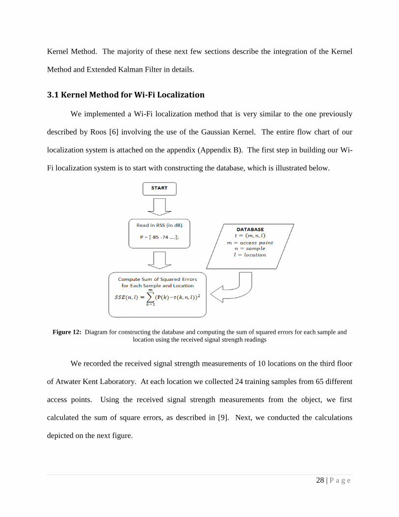
3.1 Kernel Method for Wi-Fi Localization
We implemented a Wi-Fi localization method that is very similar to the one previously
described by Roos [6] involving the use of the Gaussian Kernel. The entire flow chart of our
localization system is attached on the appendix (Appendix B). The first step in building our Wi-
Fi localization system is to start with constructing the database, which is illustrated below.
Figure 12: Diagram for constructing the database and computing the sum of squared errors for each sample and
location using the received signal strength readings
We recorded the received signal strength measurements of 10 locations on the third floor
of Atwater Kent Laboratory. At each location we collected 24 training samples from 65 different
access points. Using the received signal strength measurements from the object, we first
calculated the sum of square errors, as described in [9]. Next, we conducted the calculations
depicted on the next figure.

29 | P a g e
Figure 13: Creating and normalizing the Kernel for probability estimate
Using the SSE data and the variance value, we created the average Gaussian Kernel at
each of the 12 locations. In our experiment, we used a variance value of 0.02. In addition, we
had to tweak this value many times in order to achieve the most accurate localization
estimations. Next, with the average Gaussian Kernel, we normalized it and calculated the
probability as shown in the next figure.
Figure 14: Calculating the probability of the robot in each location using the Kernel

30 | P a g e
When we calculated the probability we assumed that value of η to be 1 as suggest in [9].
Once we have the probability values, we can then use it to estimate the position of the object.
3.2 Extended Kalman Filter for Sensor Fusion
One of the best approaches to combining the IMU gyroscope readings, the Wi-Fi RSS
measurements and the ER1 odometer data is by implementing the Extended Kalman Filter. The
Extended Kalman Filter (EKF) is an adaptive filter that models non-linear movement and state
transitions. Since the Extended Kalman Filter is a nonlinear filter, it is very practical to use it in
our case, because it can smooth the readings from our sensors to better track the robot‟s position.
Our EKF contains three stages, the initialization stage, time update stage, and measurement
update stage similar to [10].
Figure 15: Overview of the processes involved in the Extended Kalman Filter algorithm5
The purpose of the initialization stage is to initialize the state and covariance. With the state, we
can then process the data during the time update stage with the gyroscope and odometer. Finally
due to the drift imposed by the local sensors, we compensate for it during the measurement
5 “An Introduction to the Kalman Filter,” by Greg Welch and Gary Bishop. Page 11.

31 | P a g e
update phase using the Wi-Fi Kernel algorithm. The majority of the following subsections focus
on explaining each of these three stages.
3.2.1 Initialization Process
There are many approaches to implementing this filter; one of the best methods is by
developing a three state filter, implemented by [10]. To create this filter, the first step is to
identify the current state.
𝑥 = 𝑥𝑦𝜃 Eq. 1
The current state of our EKF will contain three elements, the x coordinate, y coordinate,
and the heading. These are also the main three terms that will be altered during each phase of the
EKF. During the initialization stage, we use the Wi-Fi position estimates and the magnetometer
to initialize the states. First we collect 10 samples from the Wi-Fi Kernel method outputs, which
contain the x-coordinate and y-coordinate. Then we calculate the average and standard deviation
of those measurements to be used as the initial position, and position covariance. The position
covariance is shown below.
𝑃 =
𝑥𝑠𝑡𝑑2 0 0
0 𝑦𝑠𝑡𝑑2 0
0 0 𝜃𝑠𝑡𝑑2
Eq. 2
The purpose of the covariance matrix is to model the drift to determine at what point to weight in
the Wi-Fi measurements. With high covariance values, the weight of each Wi-Fi measurement
will increase until the covariance values are decreased to a certain point. The script for this stage
32 | P a g e
can be found on Appendix J. With the establishment of the initialization stage, we proceeded to
developing the time and measurement update stages.
3.2.2 Time Update Process
During the time update phase, we update the state using only the gyroscope and the
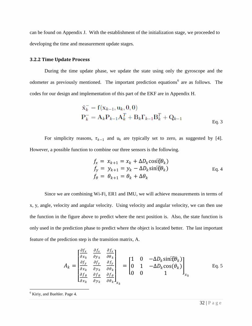
odometer as previously mentioned. The important prediction equations6 are as follows. The
codes for our design and implementation of this part of the EKF are in Appendix H.
Eq. 3
For simplicity reasons, 𝜏𝑘−1 and uk are typically set to zero, as suggested by [4].
However, a possible function to combine our three sensors is the following.
𝑓𝑥 = 𝑥𝑘+1 = 𝑥𝑘 + ∆𝐷𝑘cos(𝜃𝑘)𝑓𝑦 = 𝑦𝑘+1 = 𝑦𝑘 − ∆𝐷𝑘sin(𝜃𝑘)
𝑓𝜃 = 𝜃𝑘+1 = 𝜃𝑘 + ∆𝜃𝑘
Eq. 4
Since we are combining Wi-Fi, ER1 and IMU, we will achieve measurements in terms of
x, y, angle, velocity and angular velocity. Using velocity and angular velocity, we can then use
the function in the figure above to predict where the next position is. Also, the state function is
only used in the prediction phase to predict where the object is located better. The last important
feature of the prediction step is the transition matrix, A.
𝐴𝑘 =
𝜕𝑓𝑥
𝜕𝑥𝑘
𝜕𝑓𝑥
𝜕𝑦𝑘
𝜕𝑓𝑥
𝜕𝜃𝑘
𝜕𝑓𝑦
𝜕𝑥𝑘
𝜕𝑓𝑦
𝜕𝑦𝑘
𝜕𝑓𝑦
𝜕𝜃𝑘
𝜕𝑓𝜃
𝜕𝑥𝑘
𝜕𝑓𝜃
𝜕𝑦𝑘
𝜕𝑓𝜃
𝜕𝜃𝑘
𝑥𝑘
= 1 0 −∆𝐷𝑘sin(𝜃𝑘)0 1 −∆𝐷𝑘cos(𝜃𝑘)0 0 1
𝑥𝑘
Eq. 5
6 Kiriy, and Buehler. Page 4.
33 | P a g e
In the EKF, the state transition matrix is the Jacobian of the state, or also known as the
derivative of the state, which is shown in great detail above. Note, this matrix is only used
during the covariance update phase. Now that all the elements in the prediction state are
explained, let us move on to the measurement update phase.
3.2.3 Measurement Update Stage
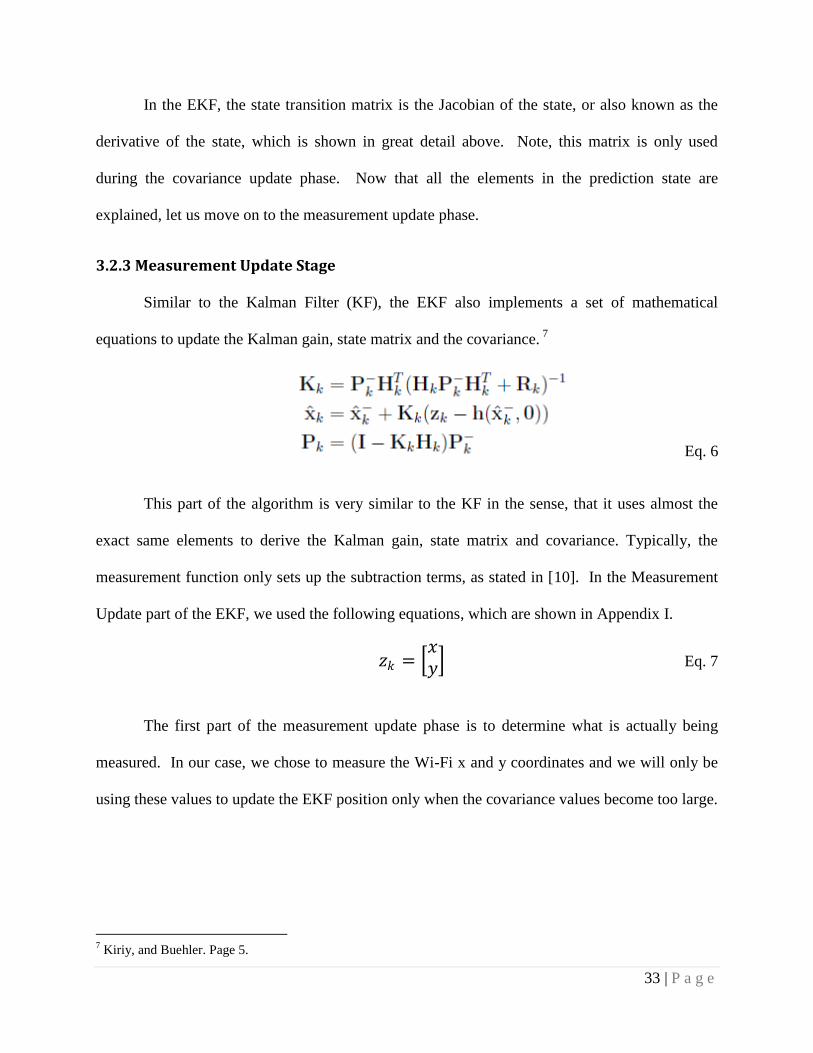
Similar to the Kalman Filter (KF), the EKF also implements a set of mathematical
equations to update the Kalman gain, state matrix and the covariance. 7
Eq. 6
This part of the algorithm is very similar to the KF in the sense, that it uses almost the
exact same elements to derive the Kalman gain, state matrix and covariance. Typically, the
measurement function only sets up the subtraction terms, as stated in [10]. In the Measurement
Update part of the EKF, we used the following equations, which are shown in Appendix I.
𝑧𝑘 = 𝑥𝑦 Eq. 7
The first part of the measurement update phase is to determine what is actually being
measured. In our case, we chose to measure the Wi-Fi x and y coordinates and we will only be
using these values to update the EKF position only when the covariance values become too large.
7 Kiriy, and Buehler. Page 5.
34 | P a g e
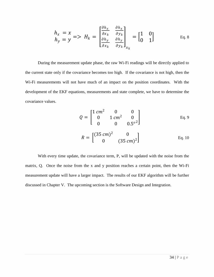
ℎ𝑥 = 𝑥ℎ𝑦 = 𝑦
=> 𝐻𝑘 =
𝜕ℎ𝑥
𝜕𝑥𝑘
𝜕ℎ𝑥
𝜕𝑦𝑘
𝜕ℎ𝑦
𝜕𝑥𝑘
𝜕ℎ𝑦
𝜕𝑦𝑘
𝑥𝑘
= 1 00 1
Eq. 8
During the measurement update phase, the raw Wi-Fi readings will be directly applied to
the current state only if the covariance becomes too high. If the covariance is not high, then the
Wi-Fi measurements will not have much of an impact on the position coordinates. With the
development of the EKF equations, measurements and state complete, we have to determine the
covariance values.
𝑄 = 1 𝑐𝑚2 0 0
0 1 𝑐𝑚2 0
0 0 0.5𝑜2 Eq. 9
𝑅 = (35 𝑐𝑚)2 0
0 (35 𝑐𝑚)2 Eq. 10
With every time update, the covariance term, P, will be updated with the noise from the
matrix, Q. Once the noise from the x and y position reaches a certain point, then the Wi-Fi
measurement update will have a larger impact. The results of our EKF algorithm will be further
discussed in Chapter V. The upcoming section is the Software Design and Integration.
35 | P a g e
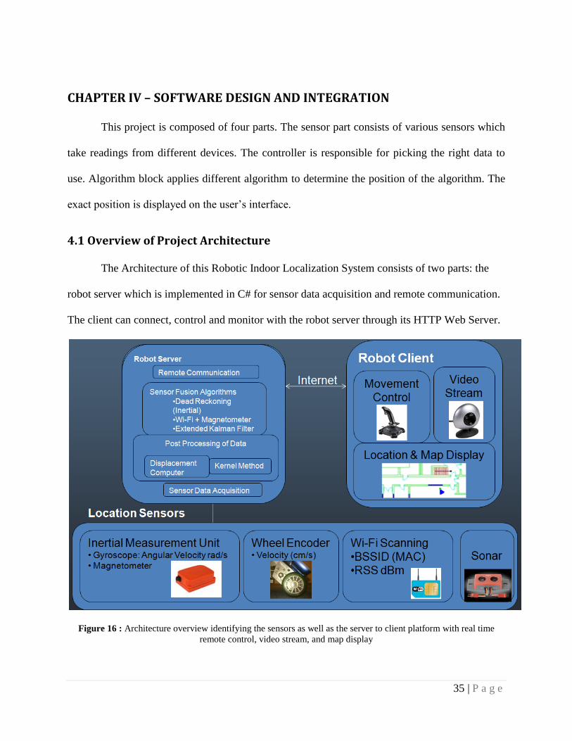
CHAPTER IV – SOFTWARE DESIGN AND INTEGRATION
This project is composed of four parts. The sensor part consists of various sensors which
take readings from different devices. The controller is responsible for picking the right data to
use. Algorithm block applies different algorithm to determine the position of the algorithm. The
exact position is displayed on the user‟s interface.
4.1 Overview of Project Architecture
The Architecture of this Robotic Indoor Localization System consists of two parts: the
robot server which is implemented in C# for sensor data acquisition and remote communication.
The client can connect, control and monitor with the robot server through its HTTP Web Server.
Figure 16 : Architecture overview identifying the sensors as well as the server to client platform with real time
remote control, video stream, and map display

36 | P a g e
The algorithms which include post processing of sensor data, Kernel Method and Extended
Kalman Filter are implemented in MATLAB and integrated into the robot server application.
4.2 JAVA Client Interface
The purpose of the Client Side JAVA Interface is to first receive the end result of the
localization algorithm using the raw data from various sensors located on the ER1 Robot. Next,
it then combines the localization information with the map of the building to plot the robot‟s
position and orientation throughout the building in real time. The JAVA interface also allows
the user to remotely navigate the ER1 Robot throughout the building and receive a real-time
video feed.
Figure 17: Robot client side of the architecture with remote control, video stream, and location/map display
37 | P a g e
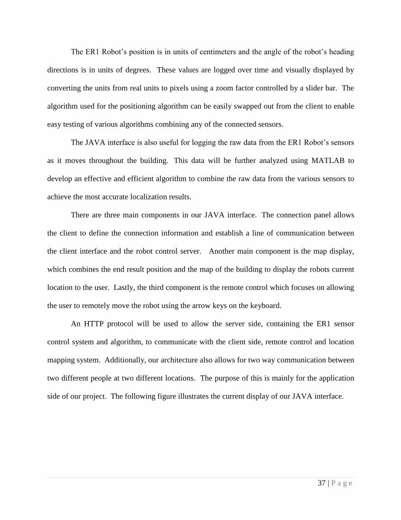
The ER1 Robot‟s position is in units of centimeters and the angle of the robot‟s heading
directions is in units of degrees. These values are logged over time and visually displayed by
converting the units from real units to pixels using a zoom factor controlled by a slider bar. The
algorithm used for the positioning algorithm can be easily swapped out from the client to enable
easy testing of various algorithms combining any of the connected sensors.
The JAVA interface is also useful for logging the raw data from the ER1 Robot‟s sensors
as it moves throughout the building. This data will be further analyzed using MATLAB to
develop an effective and efficient algorithm to combine the raw data from the various sensors to
achieve the most accurate localization results.
There are three main components in our JAVA interface. The connection panel allows
the client to define the connection information and establish a line of communication between
the client interface and the robot control server. Another main component is the map display,
which combines the end result position and the map of the building to display the robots current
location to the user. Lastly, the third component is the remote control which focuses on allowing
the user to remotely move the robot using the arrow keys on the keyboard.
An HTTP protocol will be used to allow the server side, containing the ER1 sensor
control system and algorithm, to communicate with the client side, remote control and location
mapping system. Additionally, our architecture also allows for two way communication between
two different people at two different locations. The purpose of this is mainly for the application
side of our project. The following figure illustrates the current display of our JAVA interface.
38 | P a g e
Figure 18: Client interface with the video stream on the upper right, control system on the lower right, and the
map/location display on the left
As shown in the figure above, our current JAVA interface has a velocity meter, a
command line, a video stream and a log file. Furthermore, we also added zooming capabilities
to the map of the building.
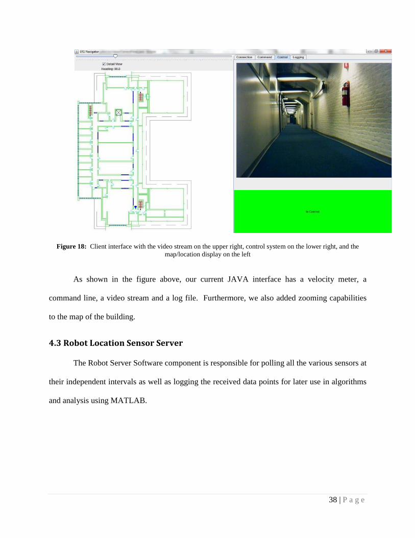
4.3 Robot Location Sensor Server
The Robot Server Software component is responsible for polling all the various sensors at
their independent intervals as well as logging the received data points for later use in algorithms
and analysis using MATLAB.
39 | P a g e
Figure 19: Robot server side of the architecture responsible for sampling the different sensors and applying the
fusion algorithm on the sensors
The Robot Server exposes an HTTP Web Interface so the client can get the current
position, controlling the robot‟s movement and receive a real-time video feed. The ER1 Locator
Server is responsible for handling requests from the client for a position, polling sensors and
triggering MATLAB to process the algorithms‟ inputs and outputs.
Currently the ER1 Remote Control Panel is used by connecting to its Remote API via the
TELNET protocol and can be used to send commands directly to the ER1 robot and receive and
handle responses. The ER1 Location Server sends position commands to the ER1‟s remote API
at every specified update interval and logs them with their timestamp. This connection is also
used to send and received commands to the robot for moving, setting speed and other Remote
API commands provided by Evolution Robotics.
40 | P a g e
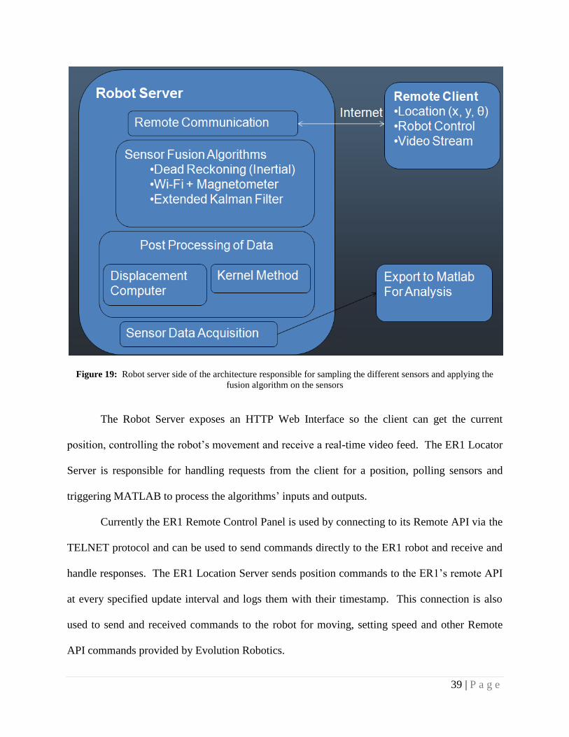
Figure 20: Robot location server interface showing the different sensors
The IMU is another sensor implemented in the ER1 Locator Server using direct
communication with the USB COM Device. The IMU is updated at a frequency of 100Hz and at
every specified update interval (currently 1 second) the ER1 Locator Server computes the total
angle displacement over that interval and runs a MATLAB script to incorporate this angular
displacement into the localization algorithm to update the current calculated position. Not only
are the current values stored for use in later algorithms, but it is stored with the past received
values so that the algorithms can take advantage of the received set of past values from all the
various sensors.
41 | P a g e
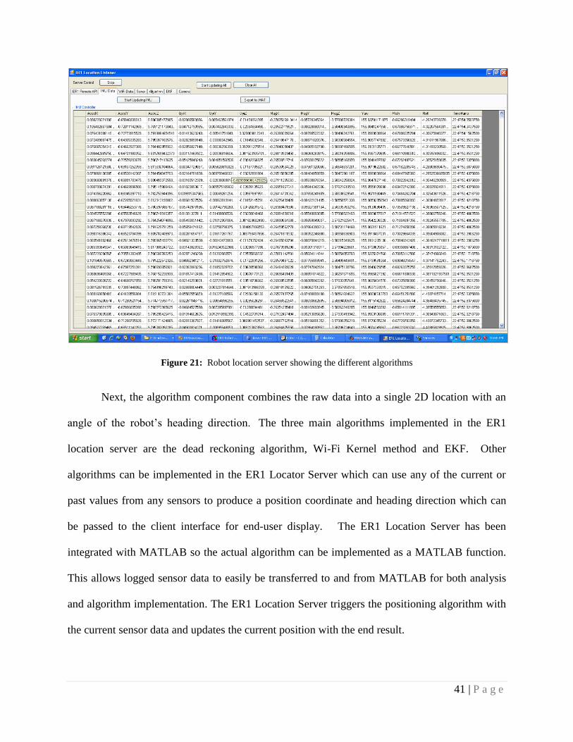
Figure 21: Robot location server showing the different algorithms
Next, the algorithm component combines the raw data into a single 2D location with an
angle of the robot‟s heading direction. The three main algorithms implemented in the ER1
location server are the dead reckoning algorithm, Wi-Fi Kernel method and EKF. Other
algorithms can be implemented in the ER1 Locator Server which can use any of the current or
past values from any sensors to produce a position coordinate and heading direction which can
be passed to the client interface for end-user display. The ER1 Location Server has been
integrated with MATLAB so the actual algorithm can be implemented as a MATLAB function.
This allows logged sensor data to easily be transferred to and from MATLAB for both analysis
and algorithm implementation. The ER1 Location Server triggers the positioning algorithm with
the current sensor data and updates the current position with the end result.
42 | P a g e
CHAPTER V – PERFORMANCE ANALYSIS
The purpose of this section is to depict the results we achieved using our current
algorithms. There are a total of three algorithms that we tested, a basic algorithm that combines
the ER1 and IMU, also known as “Dead Reckoning”, Wi-Fi Kernel Method and lastly the
Extended Kalman Filter on the ER1, IMU and Wi-Fi. Each section will illustrate the results of
the above algorithms, using a ground truth plot generated from actually measuring the robot‟s
position at a specified time. Additionally, each section will also discuss in detail the limitations
and advantages of each of the algorithms. For the “Dead Reckoning” algorithm, it displayed
good results for short term movement, whereas the Kernel method algorithm displayed good
results for long term tracking. But with the EKF which combines both of the previously
discussed algorithms, it performed the best overall by taking advantage of each of their pros.
The first subsection, however, will explain how we generated the ground truth plot.
Furthermore, we will discuss the accuracy of the overall improvement of the position estimates
when the EKF is used.
5.1 Generating Ground Truth for Reference
The first step to generating the ground truth plot was to develop an application that
allows us to measure the time and coordinates of the position of the robot. With the ability to
track the time and real position of the robot, we composed a small script that allows us to
generate the ground truth plot. The script requires the time when the robot stopped and started
moving again. In addition the positions at those two time frames are also really important. With
those data, we assume linear velocity across a certain time frame to generate the ground truth
plot. The figure below illustrates the ground truth plot application.

43 | P a g e
Figure 22: Ground truth application for logging the actual position of the robot with time
As shown from the above figure, by using the ground truth application, we can easily
keep track of the real position of the robot as well as its corresponding time. With the
measurements, we can easily pass it through our ground truth plotting script to build the ground
truth plot. Our script can be found at Appendix L. Finally, with the ground truth application and
script, we can test the results of our three algorithms. The first section is the dead reckoning
algorithm which combines the odometer from the robot with the gyroscope from the IMU.

44 | P a g e
5.2 Performance of the Dead Reckoning Algorithm
For combining the odometer of the robot and the gyroscope of the IMU data, we
implemented a very basic algorithm that tracks the change in distance and change in angle. By
using the angular velocity reading in conjunction with the linear velocity reading, we can
compute the new position and angle of the robot, given that we already know the previous
position and angle.
This algorithm primarily predicts your new position given that you achieved a certain
amount of velocity and angular velocity. The following set of equations basically outlines the
dead reckoning algorithm.
𝜽𝒕 = 𝜽𝒕−𝟏 + ∆𝜽
𝑽 𝒕 = 𝑽 𝒙𝟐 + 𝑽 𝒚
𝟐
∆𝑿 = 𝑽𝒕 × 𝐜𝐨𝐬(𝜽𝒕)
∆𝒀 = 𝑽𝒕 × 𝐬𝐢𝐧(𝜽𝒕)
𝑿𝒀 𝒕
= 𝑿𝒀 𝒕−𝟏
+ ∆𝑿∆𝒀
Eq. 12
This equation is based on the assumption that the velocity of the robot is not accurate in
X and Y directions, particularly when the robot turns. However, the total velocity will give a
more precise measurement. Using the change in angle and the total velocity, we can simply
compute the change in x direction and the change in y direction.
The angular velocity is simply added to the previous heading to achieve the new heading,
because the angular velocity has a timing interval of one second. The figure below illustrates the
results of the dead reckoning algorithm that we developed from our set of equations.
As shown in the plot below, once the angle displayed an incorrect measurement, the
entire algorithm went off course.
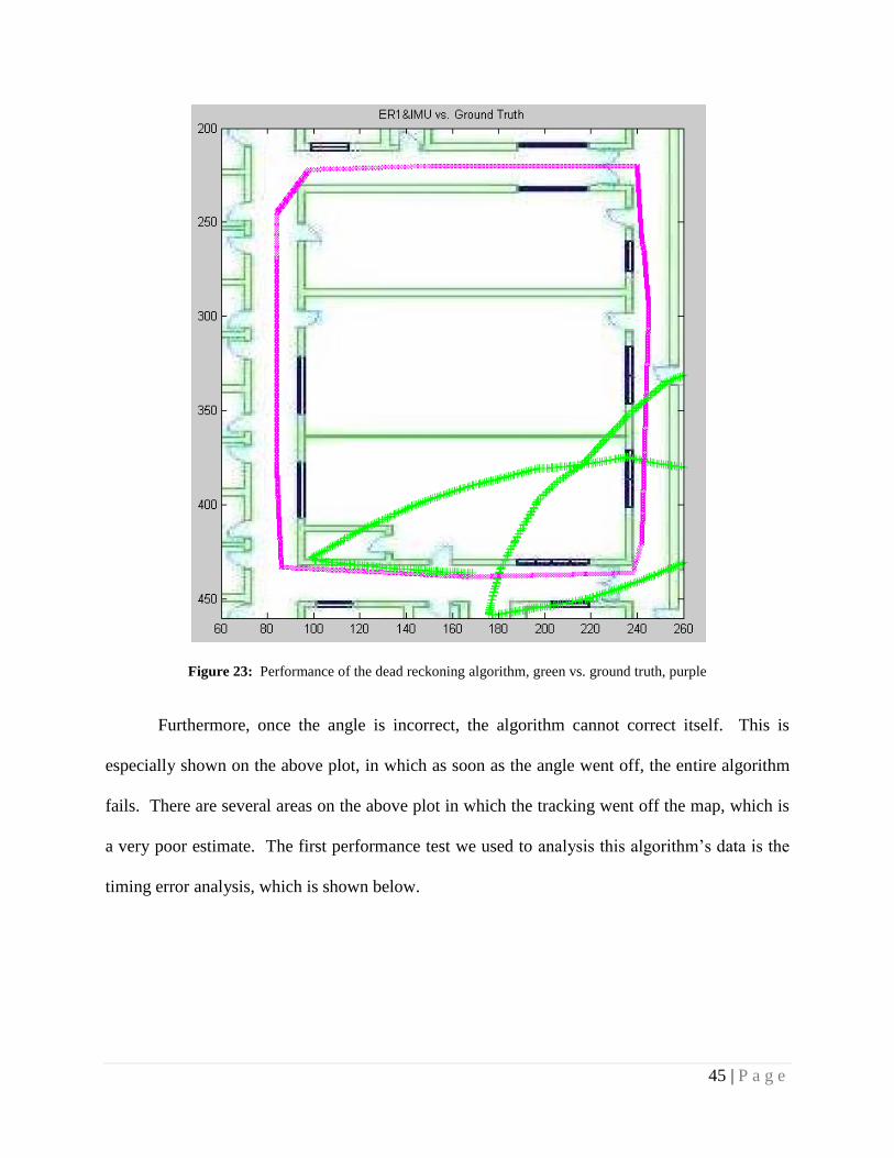
45 | P a g e
Figure 23: Performance of the dead reckoning algorithm, green vs. ground truth, purple
Furthermore, once the angle is incorrect, the algorithm cannot correct itself. This is
especially shown on the above plot, in which as soon as the angle went off, the entire algorithm
fails. There are several areas on the above plot in which the tracking went off the map, which is
a very poor estimate. The first performance test we used to analysis this algorithm‟s data is the
timing error analysis, which is shown below.
46 | P a g e
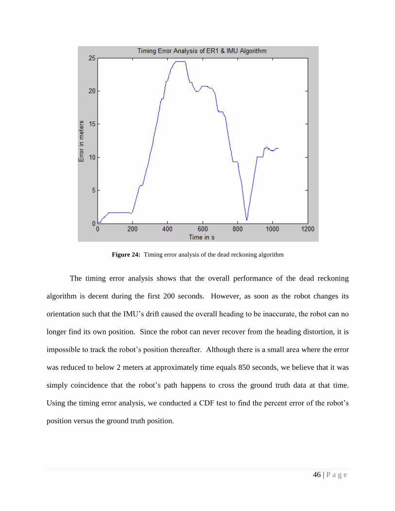
Figure 24: Timing error analysis of the dead reckoning algorithm
The timing error analysis shows that the overall performance of the dead reckoning
algorithm is decent during the first 200 seconds. However, as soon as the robot changes its
orientation such that the IMU‟s drift caused the overall heading to be inaccurate, the robot can no
longer find its own position. Since the robot can never recover from the heading distortion, it is
impossible to track the robot‟s position thereafter. Although there is a small area where the error
was reduced to below 2 meters at approximately time equals 850 seconds, we believe that it was
simply coincidence that the robot‟s path happens to cross the ground truth data at that time.
Using the timing error analysis, we conducted a CDF test to find the percent error of the robot‟s
position versus the ground truth position.
47 | P a g e
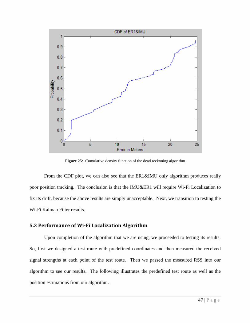
Figure 25: Cumulative density function of the dead reckoning algorithm
From the CDF plot, we can also see that the ER1&IMU only algorithm produces really
poor position tracking. The conclusion is that the IMU&ER1 will require Wi-Fi Localization to
fix its drift, because the above results are simply unacceptable. Next, we transition to testing the
Wi-Fi Kalman Filter results.
5.3 Performance of Wi-Fi Localization Algorithm
Upon completion of the algorithm that we are using, we proceeded to testing its results.
So, first we designed a test route with predefined coordinates and then measured the received
signal strengths at each point of the test route. Then we passed the measured RSS into our
algorithm to see our results. The following illustrates the predefined test route as well as the
position estimations from our algorithm.
48 | P a g e
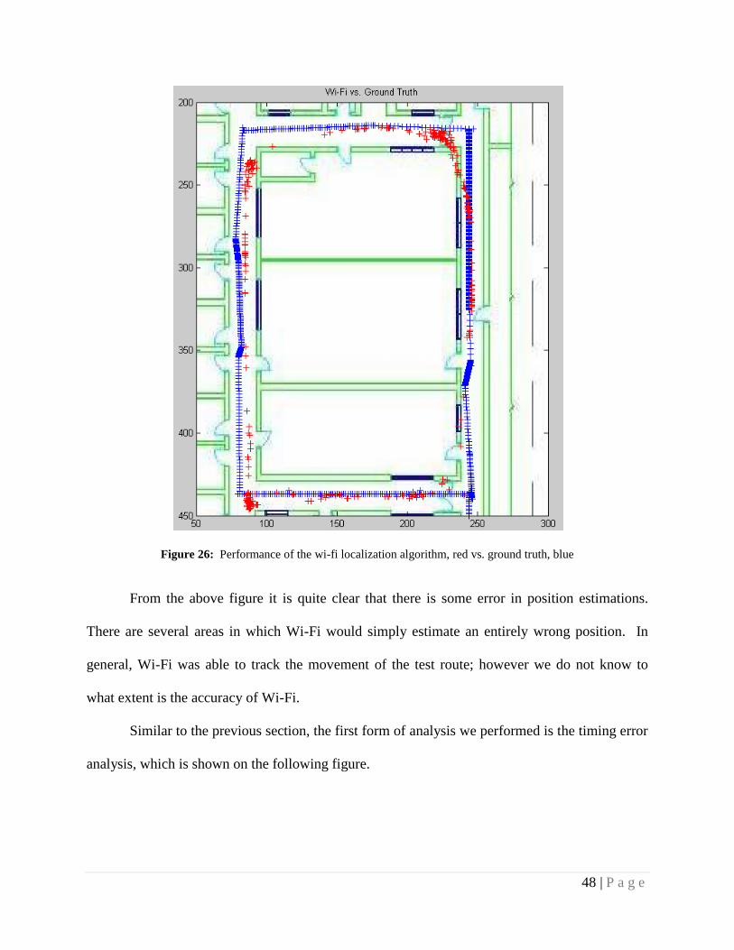
Figure 26: Performance of the wi-fi localization algorithm, red vs. ground truth, blue
From the above figure it is quite clear that there is some error in position estimations.
There are several areas in which Wi-Fi would simply estimate an entirely wrong position. In
general, Wi-Fi was able to track the movement of the test route; however we do not know to
what extent is the accuracy of Wi-Fi.
Similar to the previous section, the first form of analysis we performed is the timing error
analysis, which is shown on the following figure.
49 | P a g e
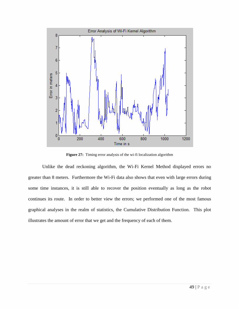
Figure 27: Timing error analysis of the wi-fi localization algorithm
Unlike the dead reckoning algorithm, the Wi-Fi Kernel Method displayed errors no
greater than 8 meters. Furthermore the Wi-Fi data also shows that even with large errors during
some time instances, it is still able to recover the position eventually as long as the robot
continues its route. In order to better view the errors; we performed one of the most famous
graphical analyses in the realm of statistics, the Cumulative Distribution Function. This plot
illustrates the amount of error that we get and the frequency of each of them.
50 | P a g e
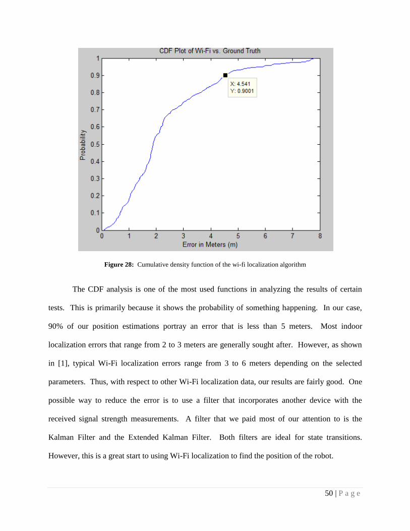
Figure 28: Cumulative density function of the wi-fi localization algorithm
The CDF analysis is one of the most used functions in analyzing the results of certain
tests. This is primarily because it shows the probability of something happening. In our case,
90% of our position estimations portray an error that is less than 5 meters. Most indoor
localization errors that range from 2 to 3 meters are generally sought after. However, as shown
in [1], typical Wi-Fi localization errors range from 3 to 6 meters depending on the selected
parameters. Thus, with respect to other Wi-Fi localization data, our results are fairly good. One
possible way to reduce the error is to use a filter that incorporates another device with the
received signal strength measurements. A filter that we paid most of our attention to is the
Kalman Filter and the Extended Kalman Filter. Both filters are ideal for state transitions.
However, this is a great start to using Wi-Fi localization to find the position of the robot.

51 | P a g e
5.4 Performance using the Extended Kalman Filter for Fusion
This next plot illustrates the Entire EKF algorithm and this is plotted versus ground truth.
The method for developing ground truth is by examining the locations in which the robot
stopped as well as the corresponding time. With those two parameters, we can easily generate a
ground truth with the assumption that the robot is traveling with linear velocity. Using those
points, we generated the ground truth in MATLAB and plotted our EKF data against it.
Figure 29: Performance of the Extended Kalman Filter algorithm, blue vs. ground truth, black
From the plot, we can see that the EKF maps the movement fairly well. The problem in
the accuracy, however, is largely due to the orientation error created from the drift of the IMU.
52 | P a g e
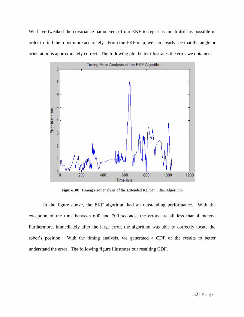
We have tweaked the covariance parameters of our EKF to reject as much drift as possible in
order to find the robot more accurately. From the EKF map, we can clearly see that the angle or
orientation is approximately correct. The following plot better illustrates the error we obtained.
Figure 30: Timing error analysis of the Extended Kalman Filter Algorithm
In the figure above, the EKF algorithm had an outstanding performance. With the
exception of the time between 600 and 700 seconds, the errors are all less than 4 meters.
Furthermore, immediately after the large error, the algorithm was able to correctly locate the
robot‟s position. With the timing analysis, we generated a CDF of the results to better
understand the error. The following figure illustrates our resulting CDF.
53 | P a g e
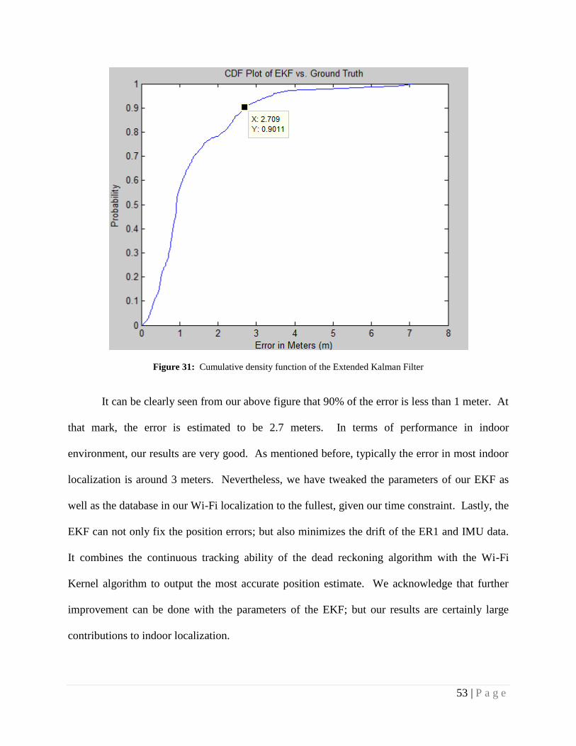
Figure 31: Cumulative density function of the Extended Kalman Filter
It can be clearly seen from our above figure that 90% of the error is less than 1 meter. At
that mark, the error is estimated to be 2.7 meters. In terms of performance in indoor
environment, our results are very good. As mentioned before, typically the error in most indoor
localization is around 3 meters. Nevertheless, we have tweaked the parameters of our EKF as
well as the database in our Wi-Fi localization to the fullest, given our time constraint. Lastly, the
EKF can not only fix the position errors; but also minimizes the drift of the ER1 and IMU data.
It combines the continuous tracking ability of the dead reckoning algorithm with the Wi-Fi
Kernel algorithm to output the most accurate position estimate. We acknowledge that further
improvement can be done with the parameters of the EKF; but our results are certainly large
contributions to indoor localization.

54 | P a g e
5.5 Comparative Performance Analysis
The purpose of this section is to compare the performances of the three algorithms: dead
reckoning, Wi-Fi Kernel method and the Extended Kalman Filter. The first plot is the timing
error analysis comparing all three algorithms.
Figure 32: Timing error analysis of the algorithms: Extended Kalman Filter, wi-fi localization, and dead reckoning
In the plot above, the first thing to note is that the dead reckoning algorithm performed
the worst. It illustrated the largest amount of error. Thus, it is only reasonable to compare the
EKF with the Wi-Fi Kernel method. From the plot, we can see that the error of Wi-Fi is
relatively large at several areas. On the other hand, the EKF only displayed a large error only at
one time frame. However, both the EKF algorithm and the Wi-Fi Kernel method were able to
correct themselves even with the large errors. After observing the timing error analysis, we used
the CDF plots from the previous sections to compare the error rates of the three algorithms.
55 | P a g e
Figure 33: Cumulative density function of the three algorithms: extended Kalman filter, wi-fi localization, and
dead reckoning
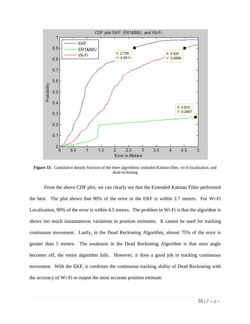
From the above CDF plot, we can clearly see that the Extended Kalman Filter performed
the best. The plot shows that 90% of the error in the EKF is within 2.7 meters. For Wi-Fi
Localization, 90% of the error is within 4.5 meters. The problem in Wi-Fi is that the algorithm is
shows too much instantaneous variations in position estimates. It cannot be used for tracking
continuous movement. Lastly, in the Dead Reckoning Algorithm, almost 75% of the error is
greater than 5 meters. The weakness in the Dead Reckoning Algorithm is that once angle
becomes off, the entire algorithm fails. However, it does a good job in tracking continuous
movement. With the EKF, it combines the continuous tracking ability of Dead Reckoning with
the accuracy of Wi-Fi to output the most accurate position estimate.
56 | P a g e
CHAPTER VI CONCLUSION
In conclusion, we designed, implemented, and tested a location aware multi-sensor
robotic platform for indoor applications, taking advantage of an existing Wi-Fi infrastructure.
Our platform has three main features. The first feature is a user friendly graphical user interface
with the flexibility to log data using different fusion algorithms for evaluation and post
processing. One of the purposes of the software architecture is that it allows for the application
of location aware robots. The interface contains a real time map display, remote control, and
data logging capabilities. With the data log feature, we can easily test and evaluate the
performances of different sensor combinations and algorithms.
The second feature of our Major Qualifying Project is the statistical Wi-Fi localization
algorithm. This algorithm makes use of the existing Wi-Fi infrastructure inside a building which
makes it an inexpensive sensor with low power consumption. The algorithm we used does not
require a lot of data training. We went to twelve different locations and logged twenty-four
samples in each location. These twenty-four samples are logged in four different directions.
Furthermore, by using an existing infrastructure, and developing a software-based position-
tracking engine, the performance of the algorithm can be easily accessed and evaluated. The
algorithm itself can be easily modified to further enhance the performance.
The last feature is that we designed and implemented the Extended Kalman Filter as the
core fusion algorithm that takes advantage of the short term tracking ability of our local sensors
such as the Odometer and Gyroscope and the long term tracking ability of our global sensors
such as Wi-Fi. By using our global sensor, Wi-Fi RSS readings, we can successfully correct the
drift that is imposed by the inertial sensors: Gyroscope, and Odometer. Without the reference
57 | P a g e
aided by Wi-Fi, the inertial algorithm (dead-reckoning) achieved an error rate greater than 20
meters. On the other hand, Wi-Fi alone achieved ninety percent of the error to be within 4.5
meters of its actual position. The discrepancy can be explained by Wi-Fi‟s slow response to
instantaneous change as well as its short term variations. Lastly, with the EKF which takes
advantage of the inertial system for short term tracking, and Wi-Fi Kernel method for long term
tracking, it displayed that ninety percent of the error is within 2.7 meters which is very good in
terms of indoor localization. Our fusion algorithm performed the best overall; however future
work can be implemented to further improve its accuracy.
Future Work
Overall, we accomplished most of our objectives in this project; however we can further
improve the Extended Kalman Filter algorithm. First, Particle filter is another widely used
fusion algorithm for indoor localization. In the future, the performance of the Particle filter can
be compared with Extended Kalman Filter to see which fusion algorithm performs better in
indoor environment. Secondly, we can use the map of the building as a reference to improve the
accuracy of the EKF. Using the map, we can identify the walls, rooms, and obstacles within the
building in order to prevent the robot from collision and going through the walls. Thirdly, we
have not fully tested how changing the covariance matrix of the EKF will affect the system as a
whole. The Kalman Filter is a smoothing filter and it smoothes out the noise and drift introduced
by local sensors as well as global sensors so that it can combine the advantages of the various
sensors. However, it is slow in response to instantaneous changes in movement. For the future
work, the second order Extended Kalman filter can be implemented to model the instantaneous
velocity and heading change so that it will have better real time performance. Most of our
testing has been adjusting the parameters in the EKF, and observing its resulting behavior. A lot
58 | P a g e
of experiment and measurements remain open in this part of the research. Only a first order
model is implemented in this project, where the effects of including the second order model have
not yet been tested. This can be done by modifying the state equation and the two update
equations. With the second order model, we believe that we can better track instantaneous
changes. The last algorithm improvement is that we have yet to incorporate the sonar sensors.
We believe that with the aid of the sonar sensors, we can better track the heading of the robot as
well as using it for obstacle detection for autonomous movement.
Besides algorithm improvement, we can also develop both autonomous and manned
movement applications using our multi-sensor location aware robot. Some of the autonomous
applications that we can implement include guided tours to provide better tour experience. In
our vision, such applications can be employed at museums, art galleries as well as universities.
In terms of manned movement applications, telecommunication can be developed upon the
algorithm we have already designed and these types of application can be used in factories and
science lab to provide firsthand experience for those who are not able to travel. With the aid of
location information, many indoor robotics services can be made possible.
Acknowledgements
The authors would like to express their thanks to Professor Kaveh Pahlavan and his PhD
students Ferit Ozan Akgul and Yunxing Ye for their support, assistance and inspiration during
the implementation period of this work.

59
APPENDICES
Appendix A – ER-1 Position & Velocity Measurements (10, 15, 25, 50 in.)
Case2 cwins lab t ≈ 4
s
instructed: 10 inches (25.4 cm)
measured(cm) comp(cm) measured
velocity(cm/s)
comp velocity(cm/s)
24.13 22.9 - 0.0 6.0325 5.72
24.4475 45.9 - 0.0 6.11 5.75
23.8125 68.9 - 0.0 5.95 5.75
24.4475 91.8 - 0.0 6.11 5.72
23.495 114.9 - 0.1 5.87 5.78
24.13 138.1 - 0.1 6.0325 5.8
22.86 161.3 - 0.2 5.72 5.8
23.495 184.4 - 0.3 5.87 5.78
23.8125 207.7 - 0.3 5.95 5.83
23.8125 230.8 - 0.4 5.95 5.78
mean: 23.84425 5.9595 5.771 Table 3: move 10i test results
Case3 cwins lab t ≈ 6 s instructed: 15 inches (38.1 cm)
measured(cm) comp(cm) measured
velocity(cm/s)
comp velocity(cm/s)
37.94 36.4 - 0.0 6.32 6.06
38.03 72.7 - 0.0 6.34 6.05
37.87 109.7 - 0.0 6.32 6.17
37.94 145.8 - 0.1 6.32 6.02
38.03 182.2 - 0.2 6.34 6.07
37.8 212.9 - 0.2 6.3 6.12
37.75 250.0 - 0.3 6.29 6.18
38.03 286.6 - 0.4 6.34 6.1
37.94 321.2 - 0.4 6.32 5.77
37.85 357.5 - 0.5 6.31 6.05
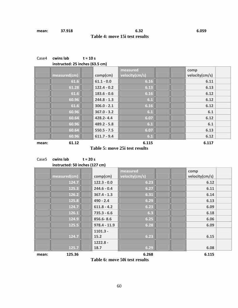
60
mean: 37.918 6.32 6.059 Table 4: move 15i test results
Case4 cwins lab t ≈ 10 s instructed: 25 inches (63.5 cm)
measured(cm) comp(cm) measured velocity(cm/s)
comp velocity(cm/s)
61.6 61.1 - 0.0 6.16 6.11
61.28 122.4 - 0.2 6.13 6.13
61.6 183.6 - 0.6 6.16 6.12
60.96 244.8 - 1.3 6.1 6.12
61.6 306.0 - 2.1 6.16 6.12
60.96 367.0 - 3.2 6.1 6.1
60.64 428.2- 4.4 6.07 6.12
60.96 489.2 - 5.8 6.1 6.1
60.64 550.5 - 7.5 6.07 6.13
60.96 611.7 - 9.4 6.1 6.12
mean: 61.12 6.115 6.117 Table 5: move 25i test results
Case5 cwins lab t ≈ 20 s instructed: 50 inches (127 cm)
measured(cm) comp(cm) measured velocity(cm/s)
comp velocity(cm/s)
124.7 122.3 - 0.0 6.23 6.12
125.3 244.6 - 0.4 6.27 6.11
126.2 367.4 - 1.3 6.31 6.14
125.8 490 - 2.4 6.29 6.13
124.7 611.8 - 4.2 6.23 6.09
126.1 735.3 - 6.6 6.3 6.18
124.9 856.6- 8.6 6.25 6.06
125.5 978.4 - 11.9 6.28 6.09
124.7 1101.3 - 15.2 6.23 6.15
125.7 1222.8 - 18.7 6.29 6.08
mean: 125.36 6.268 6.115 Table 6: move 50i test results

61
The first conclusion that can be drawn from the velocity and position
measurements above is that as the step size increases, the difference between actual
measured velocity and computer measured velocity decreases.
Figure 34: Computer Velocity vs. Measured Velocity
After carefully examining the plot above, Case 4, where the step size is 25 inches
seems to be the best case in terms of the accuracy of velocity. Once the step size is
increased to 50 inches the actual velocity and the measured velocity starts to diverge from
each other. The drift can also be compared between these five different cases. The next
figure shows the initial positions, and the final positions of five cases.
0
1
2
3
4
5
6
7
1 2 3 4 5
Ve
loci
ty(m
/s)
Cases
Computer Velocity vs Measured Velocity
Actual Velocity
Computer Velocity
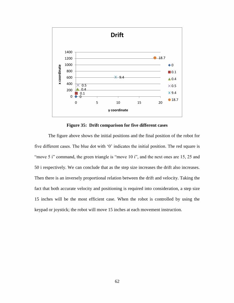
62
Figure 35: Drift comparison for five different cases
The figure above shows the initial positions and the final position of the robot for
five different cases. The blue dot with „0‟ indicates the initial position. The red square is
“move 5 i” command, the green triangle is “move 10 i”, and the next ones are 15, 25 and
50 i respectively. We can conclude that as the step size increases the drift also increases.
Then there is an inversely proportional relation between the drift and velocity. Taking the
fact that both accurate velocity and positioning is required into consideration, a step size
15 inches will be the most efficient case. When the robot is controlled by using the
keypad or joystick; the robot will move 15 inches at each movement instruction.
00.10.40.5
9.4
18.7
0
200
400
600
800
1000
1200
1400
0 5 10 15 20
x co
ord
inat
e
y coordinate
Drift
0
0.1
0.4
0.5
9.4
18.7
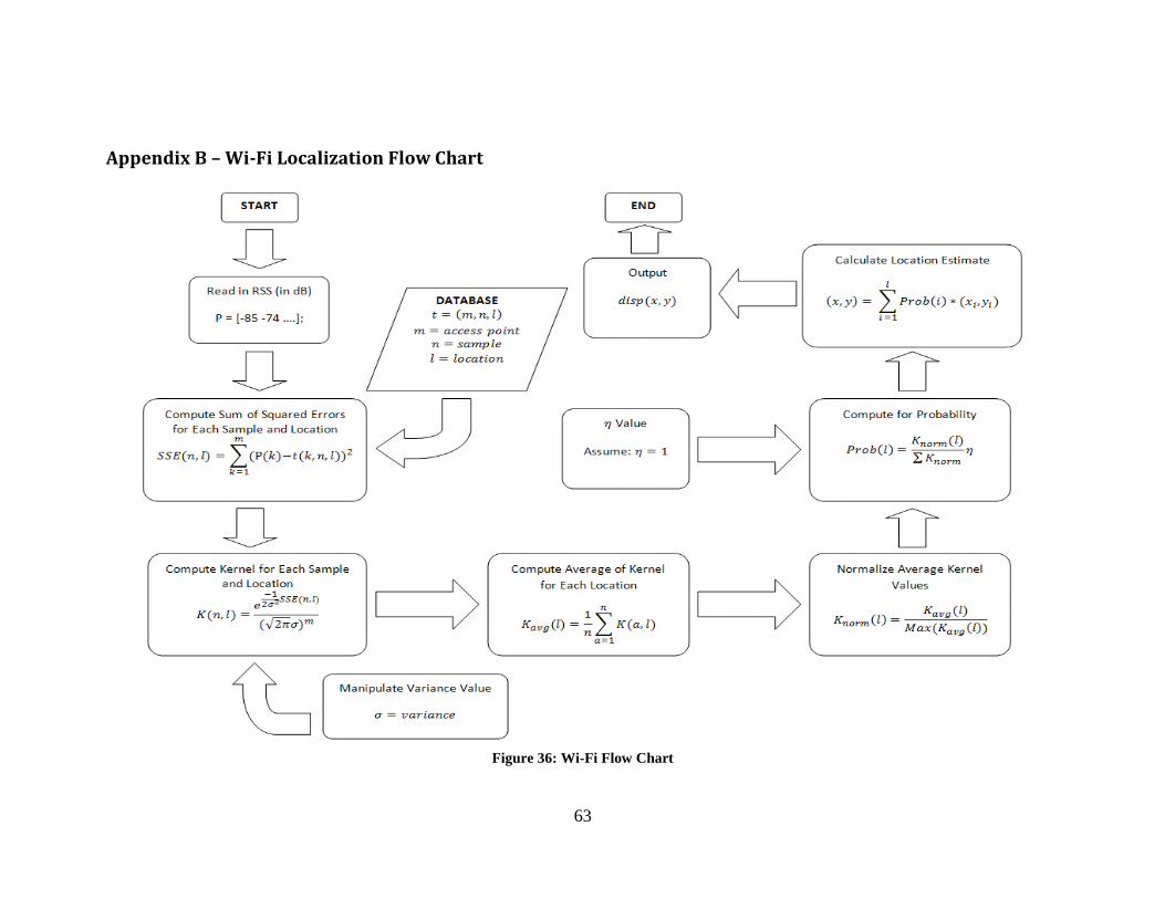
63
Appendix B – Wi-Fi Localization Flow Chart
Figure 36: Wi-Fi Flow Chart

64
Appendix C – sonar.c (Code that is developed for Vex Ultrasonic Rangefinder)
#include "BuiltIns.h"
void main(void)
{
char result[10];
//TwoWheelDrive(2,1); // use a two wheel drive robot
StartUltrasonic(1, 7); // start ultrasonic sensor ranging
//Drive(70, 0); // start robot driving forward
GetUltrasonic(1, 7); // continue while distance > 15”
sprintf(result,"%d",GetUltrasonic(1,7));
//Drive(0, 0); // stop driving
PrintToScreen(result);
StopUltrasonic(1,7);
}
Four_sonar.c
#include "BuiltIns.h"
void main(void)
{
char result1[10];
char result2[10];
char result3[10];
char result4[10];
StartUltrasonic(1, 11); // start ultrasonic sensor ranging
StartUltrasonic(2, 12);
StartUltrasonic(3, 13);
StartUltrasonic(4, 14);
sprintf(result1,"%d",GetUltrasonic(1,11));
sprintf(result2,"%d",GetUltrasonic(2,12));
sprintf(result3,"%d",GetUltrasonic(3,13));
sprintf(result4,"%d",GetUltrasonic(4,14));
PrintToScreen(result1);
PrintToScreen(result2);
PrintToScreen(result3);
PrintToScreen(result4);
StopUltrasonic(1,11);
StopUltrasonic(2,12);
StopUltrasonic(3,13);
StopUltrasonic(4,14);
}
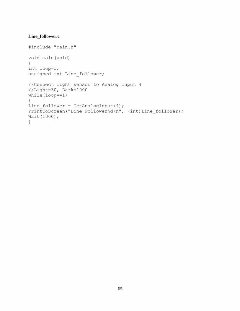
65
Line_follower.c
#include "Main.h"
void main(void)
{
int loop=1;
unsigned int Line_follower;
//Connect light sensor to Analog Input 4
//Light=30, Dark=1000
while(loop==1)
{
Line_follower = GetAnalogInput(4);
PrintToScreen("Line Follower%d\n", (int)Line_follower);
Wait(1000);
}
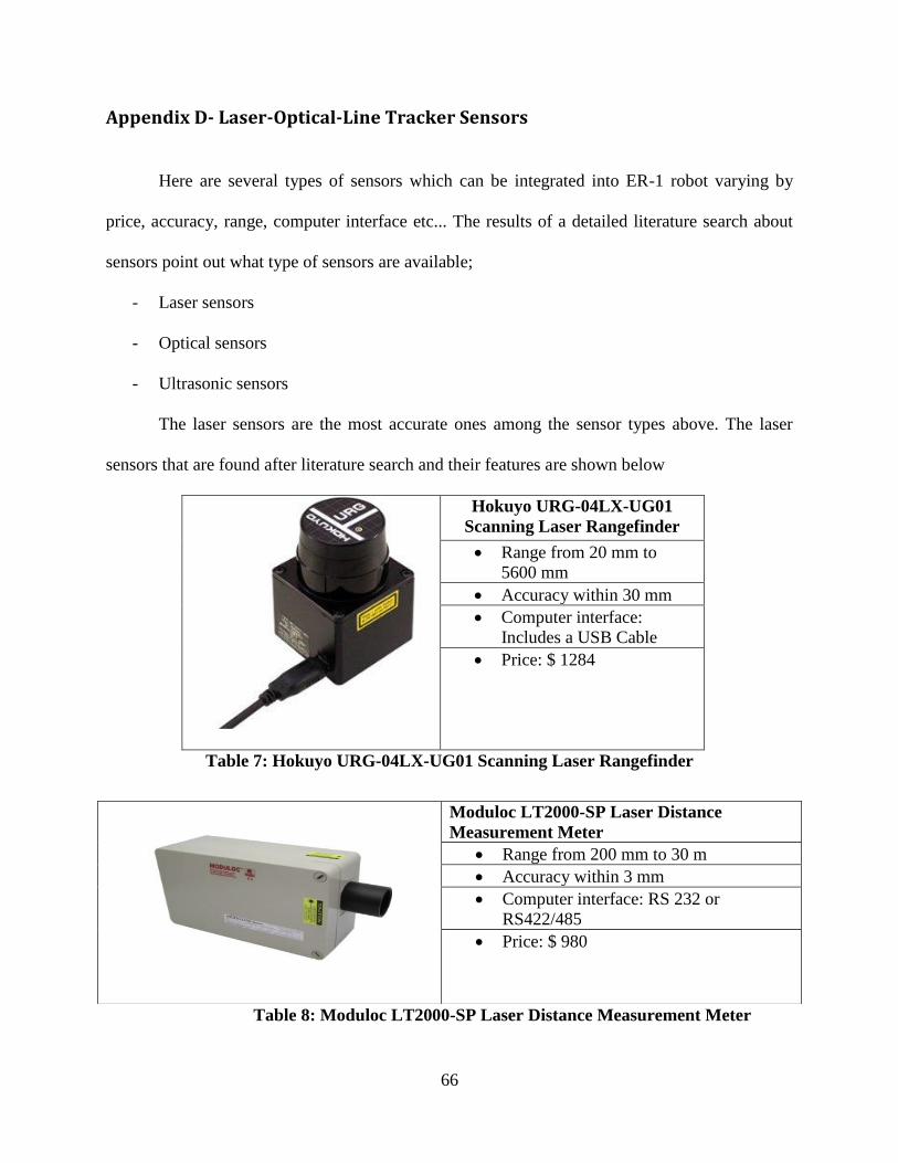
66
Appendix D- Laser-Optical-Line Tracker Sensors
Here are several types of sensors which can be integrated into ER-1 robot varying by
price, accuracy, range, computer interface etc... The results of a detailed literature search about
sensors point out what type of sensors are available;
- Laser sensors
- Optical sensors
- Ultrasonic sensors
The laser sensors are the most accurate ones among the sensor types above. The laser
sensors that are found after literature search and their features are shown below
Hokuyo URG-04LX-UG01
Scanning Laser Rangefinder
Range from 20 mm to
5600 mm
Accuracy within 30 mm
Computer interface:
Includes a USB Cable
Price: $ 1284
Table 7: Hokuyo URG-04LX-UG01 Scanning Laser Rangefinder
Table 8: Moduloc LT2000-SP Laser Distance Measurement Meter
Moduloc LT2000-SP Laser Distance
Measurement Meter
Range from 200 mm to 30 m
Accuracy within 3 mm
Computer interface: RS 232 or
RS422/485
Price: $ 980

67
Laser distance sensors are very accurate as seen in their features above. The range they
can take measurements is also very long. The major problem with laser distance sensors are their
price. Since we have $400 budget to accomplish this Major Qualifying Project, it would not be
meaningful to spend the entire budget on one sensor. Therefore; other sensor types, such as
infrared and ultrasonic sensors are given priority in literature search. The optical sensors that are
found after literature search and their features are shown below;
Table 9: Leuze ODSL8 Optical Distance Sensor
Table 10: Leuze ODS 96 Series Optical Distance Sensor
The literature search about optical distance sensors prove that; using this type of sensors
would be more appropriate in terms of staying in the limits of budget. Optical sensors have lower
range than laser sensors; yet their accuracy is also lower than the accuracy of laser sensors. The
advantage of optical sensors over laser sensors is their lower price. As a result; ultrasonic sensors
Leuze ODSL8 Optical Distance Sensor
Range from 20 mm to 500 mm
Accuracy within 10 mm
Computer interface: RS 232 or RS485
Price: $ 631
Leuze ODS 96 Series Optical Distance Sensor
Range from 60 mm to 5000 mm
Accuracy within 10 mm
Computer interface: RS 232 or RS485
Price: $ 689
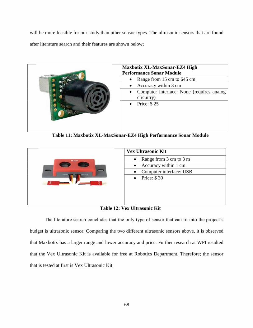
68
will be more feasible for our study than other sensor types. The ultrasonic sensors that are found
after literature search and their features are shown below;
Table 11: Maxbotix XL-MaxSonar-EZ4 High Performance Sonar Module
Table 12: Vex Ultrasonic Kit
The literature search concludes that the only type of sensor that can fit into the project‟s
budget is ultrasonic sensor. Comparing the two different ultrasonic sensors above, it is observed
that Maxbotix has a larger range and lower accuracy and price. Further research at WPI resulted
that the Vex Ultrasonic Kit is available for free at Robotics Department. Therefore; the sensor
that is tested at first is Vex Ultrasonic Kit.
Maxbotix XL-MaxSonar-EZ4 High
Performance Sonar Module
Range from 15 cm to 645 cm
Accuracy within 3 cm
Computer interface: None (requires analog
circuitry)
Price: $ 25
Vex Ultrasonic Kit
Range from 3 cm to 3 m
Accuracy within 1 cm
Computer interface: USB
Price: $ 30

69
A More Different Approach, Line Tracker
Vex Company has another sensor called; the line tracker. This sensor has a very simple
working structure similar to the ultrasound sensor. It basically has an infrared sensor on it which
scans the colors of the surfaces that it is facing. The line tracker sensor is able to detect wide
margins of change in colors. For instance, if we draw a yellow line on a dark surface, the line
tracker sensor makes it possible for the robot to follow that yellow line, therefore to go straight.
Since drifting is the major problem we have with the movement of ER-1 robot, we can use this
line tracker sensor to make the robot follow a pre-defined path.
The problem with the usage of line tracker sensor is its incompatibility with the user
interface. One of the goals of our project is to control the robot through remote wireless
connection without seeing it. In this case, if the robot follows a pre-defined path our application
loses one if its main features. Therefore we should come up with alternative methods to
implement the line tracker sensor. The sample code for line tracker sensor can be found in
Appendix C.
Figure 37: Vex Line Tracker Sensor
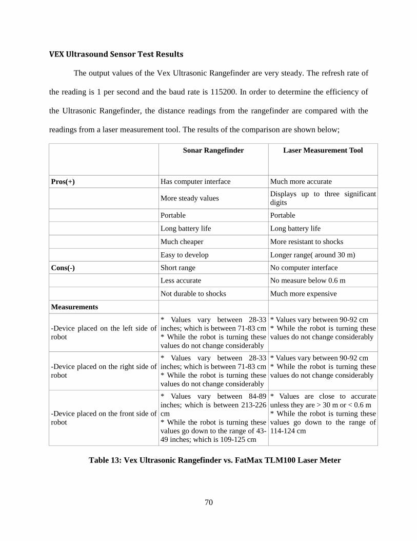
70
VEX Ultrasound Sensor Test Results
The output values of the Vex Ultrasonic Rangefinder are very steady. The refresh rate of
the reading is 1 per second and the baud rate is 115200. In order to determine the efficiency of
the Ultrasonic Rangefinder, the distance readings from the rangefinder are compared with the
readings from a laser measurement tool. The results of the comparison are shown below;
Sonar Rangefinder
Laser Measurement Tool
Pros(+) Has computer interface Much more accurate
More steady values Displays up to three significant
digits
Portable Portable
Long battery life Long battery life
Much cheaper More resistant to shocks
Easy to develop Longer range( around 30 m)
Cons(-) Short range No computer interface
Less accurate No measure below 0.6 m
Not durable to shocks Much more expensive
Measurements
-Device placed on the left side of
robot
* Values vary between 28-33
inches; which is between 71-83 cm * While the robot is turning these
values do not change considerably
* Values vary between 90-92 cm * While the robot is turning these
values do not change considerably
-Device placed on the right side of
robot
* Values vary between 28-33
inches; which is between 71-83 cm * While the robot is turning these
values do not change considerably
* Values vary between 90-92 cm * While the robot is turning these
values do not change considerably
-Device placed on the front side of
robot
* Values vary between 84-89
inches; which is between 213-226
cm * While the robot is turning these
values go down to the range of 43-
49 inches; which is 109-125 cm
* Values are close to accurate
unless they are > 30 m or < 0.6 m * While the robot is turning these
values go down to the range of
114-124 cm
Table 13: Vex Ultrasonic Rangefinder vs. FatMax TLM100 Laser Meter

71
The comparison between the Vex Ultrasonic Kit and TLM100 Laser Meter proved that
using ultrasonic rangefinder does not provide as accurate readings as the laser meter does; but it
is much more feasible. Therefore; a further research to find less expensive and at the same time
more accurate sensors is required. Following are the two demos that are prepared to test the
efficiency of Ultrasonic Rangefinder and Laser Meter on the third floor of the Atwater Kent
Building around the hallway. Figure 39 summarizes the measurements of position in three
different cases; when the sensor is mounted to the front side of the robot, right side of the robot
and finally the left side of the robot.
Figure 38: Laser Readings and Ultrasonic Sensor Readings
( http://img705.imageshack.us/img705/4767/laserreadings.gif
http://img20.imageshack.us/img20/2941/sensorreadings.gif )
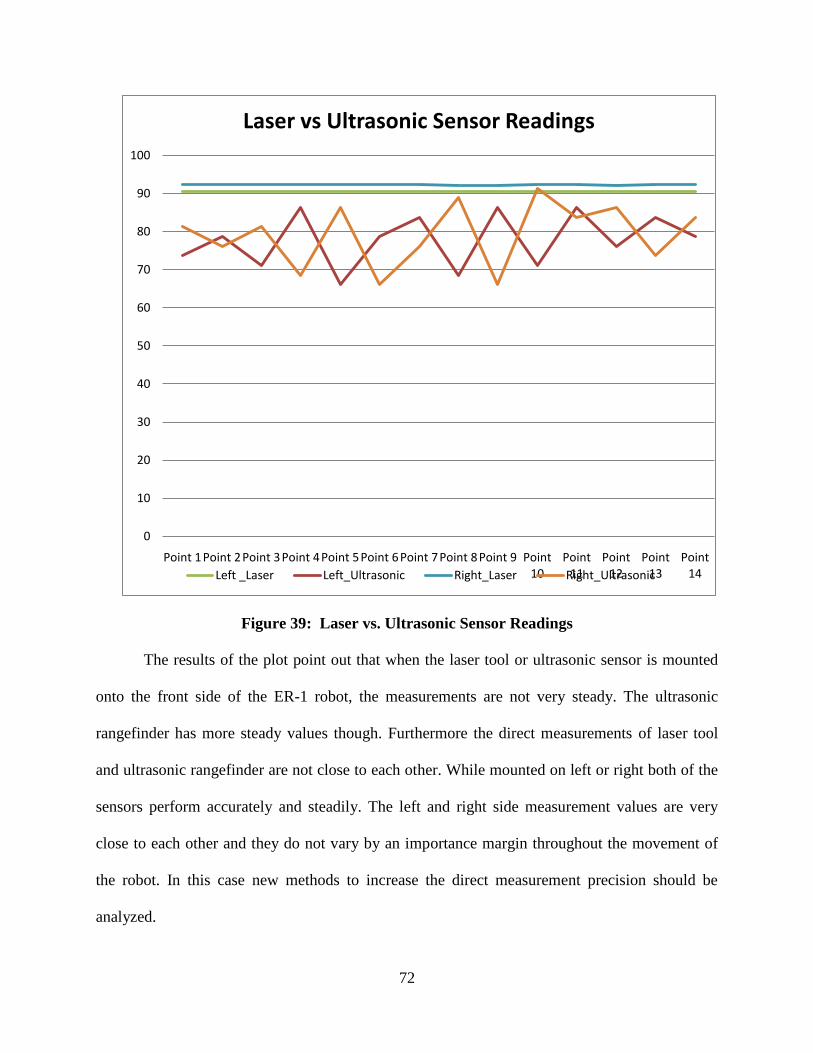
72
Figure 39: Laser vs. Ultrasonic Sensor Readings
The results of the plot point out that when the laser tool or ultrasonic sensor is mounted
onto the front side of the ER-1 robot, the measurements are not very steady. The ultrasonic
rangefinder has more steady values though. Furthermore the direct measurements of laser tool
and ultrasonic rangefinder are not close to each other. While mounted on left or right both of the
sensors perform accurately and steadily. The left and right side measurement values are very
close to each other and they do not vary by an importance margin throughout the movement of
the robot. In this case new methods to increase the direct measurement precision should be
analyzed.
0
10
20
30
40
50
60
70
80
90
100
Point 1Point 2Point 3Point 4Point 5Point 6Point 7Point 8Point 9 Point 10
Point 11
Point 12
Point 13
Point 14
Laser vs Ultrasonic Sensor Readings
Left _Laser Left_Ultrasonic Right_Laser Right_Ultrasonic
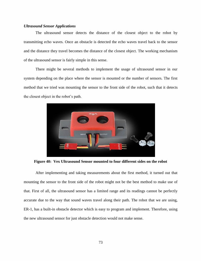
73
Ultrasound Sensor Applications
The ultrasound sensor detects the distance of the closest object to the robot by
transmitting echo waves. Once an obstacle is detected the echo waves travel back to the sensor
and the distance they travel becomes the distance of the closest object. The working mechanism
of the ultrasound sensor is fairly simple in this sense.
There might be several methods to implement the usage of ultrasound sensor in our
system depending on the place where the sensor is mounted or the number of sensors. The first
method that we tried was mounting the sensor to the front side of the robot, such that it detects
the closest object in the robot‟s path.
Figure 40: Vex Ultrasound Sensor mounted to four different sides on the robot
After implementing and taking measurements about the first method, it turned out that
mounting the sensor to the front side of the robot might not be the best method to make use of
that. First of all, the ultrasound sensor has a limited range and its readings cannot be perfectly
accurate due to the way that sound waves travel along their path. The robot that we are using,
ER-1, has a built-in obstacle detector which is easy to program and implement. Therefore, using
the new ultrasound sensor for just obstacle detection would not make sense.
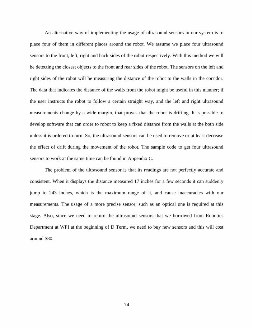
74
An alternative way of implementing the usage of ultrasound sensors in our system is to
place four of them in different places around the robot. We assume we place four ultrasound
sensors to the front, left, right and back sides of the robot respectively. With this method we will
be detecting the closest objects to the front and rear sides of the robot. The sensors on the left and
right sides of the robot will be measuring the distance of the robot to the walls in the corridor.
The data that indicates the distance of the walls from the robot might be useful in this manner; if
the user instructs the robot to follow a certain straight way, and the left and right ultrasound
measurements change by a wide margin, that proves that the robot is drifting. It is possible to
develop software that can order to robot to keep a fixed distance from the walls at the both side
unless it is ordered to turn. So, the ultrasound sensors can be used to remove or at least decrease
the effect of drift during the movement of the robot. The sample code to get four ultrasound
sensors to work at the same time can be found in Appendix C.
The problem of the ultrasound sensor is that its readings are not perfectly accurate and
consistent. When it displays the distance measured 17 inches for a few seconds it can suddenly
jump to 243 inches, which is the maximum range of it, and cause inaccuracies with our
measurements. The usage of a more precise sensor, such as an optical one is required at this
stage. Also, since we need to return the ultrasound sensors that we borrowed from Robotics
Department at WPI at the beginning of D Term, we need to buy new sensors and this will cost
around $80.
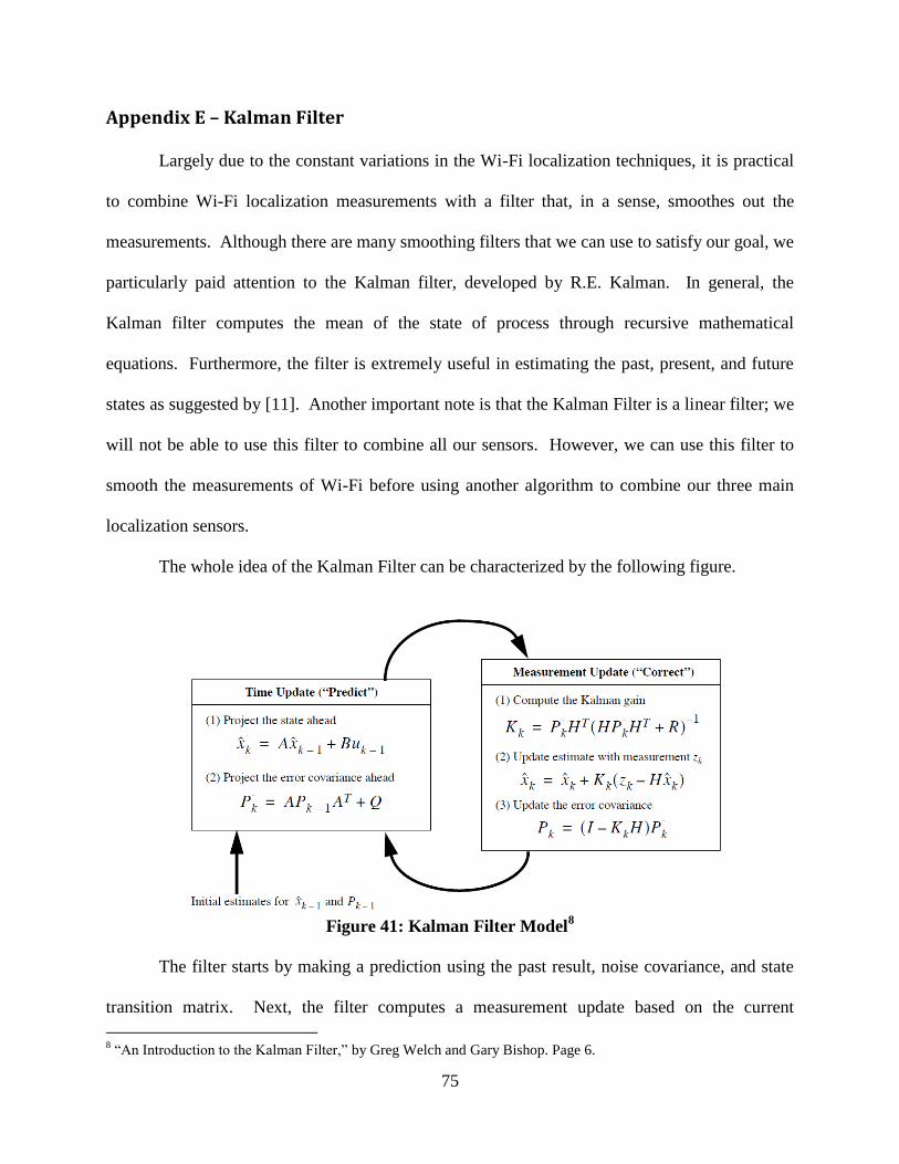
75
Appendix E – Kalman Filter
Largely due to the constant variations in the Wi-Fi localization techniques, it is practical
to combine Wi-Fi localization measurements with a filter that, in a sense, smoothes out the
measurements. Although there are many smoothing filters that we can use to satisfy our goal, we
particularly paid attention to the Kalman filter, developed by R.E. Kalman. In general, the
Kalman filter computes the mean of the state of process through recursive mathematical
equations. Furthermore, the filter is extremely useful in estimating the past, present, and future
states as suggested by [11]. Another important note is that the Kalman Filter is a linear filter; we
will not be able to use this filter to combine all our sensors. However, we can use this filter to
smooth the measurements of Wi-Fi before using another algorithm to combine our three main
localization sensors.
The whole idea of the Kalman Filter can be characterized by the following figure.
Figure 41: Kalman Filter Model
8
The filter starts by making a prediction using the past result, noise covariance, and state
transition matrix. Next, the filter computes a measurement update based on the current
8 “An Introduction to the Kalman Filter,” by Greg Welch and Gary Bishop. Page 6.
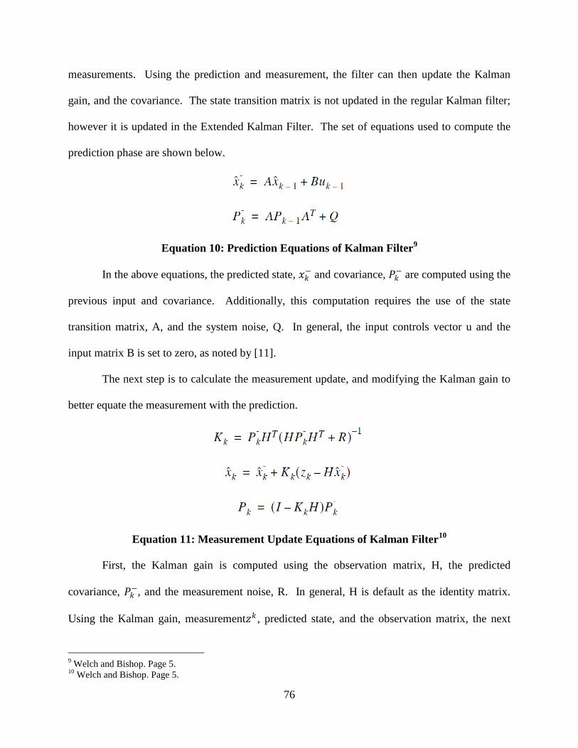
76
measurements. Using the prediction and measurement, the filter can then update the Kalman
gain, and the covariance. The state transition matrix is not updated in the regular Kalman filter;
however it is updated in the Extended Kalman Filter. The set of equations used to compute the
prediction phase are shown below.
Equation 10: Prediction Equations of Kalman Filter9
In the above equations, the predicted state, 𝑥𝑘− and covariance, 𝑃𝑘
− are computed using the
previous input and covariance. Additionally, this computation requires the use of the state
transition matrix, A, and the system noise, Q. In general, the input controls vector u and the
input matrix B is set to zero, as noted by [11].
The next step is to calculate the measurement update, and modifying the Kalman gain to
better equate the measurement with the prediction.
Equation 11: Measurement Update Equations of Kalman Filter10
First, the Kalman gain is computed using the observation matrix, H, the predicted
covariance, 𝑃𝑘−, and the measurement noise, R. In general, H is default as the identity matrix.
Using the Kalman gain, measurement𝑧𝑘 , predicted state, and the observation matrix, the next
9 Welch and Bishop. Page 5.
10 Welch and Bishop. Page 5.

77
equation will then update the state. Lastly, the filter updates the covariance. It is also important
to note that the covariance is fed back into the prediction phase to update the predicted
covariance. Below are the results of a Kalman filter.
Figure 42: Kalman Filter Results11
The cross marks represent the noisy measurements, the straight line is the true voltage
value and the curve is the Kalman Filter output. As shown above, the Kalman filter was able to
adapt the noisy measurements to approximate the true value. By choosing a constant for the
prediction noise Q, and the measurement noise R, the filter will update very quickly the
covariance, P and the Kalman gain, K, as noted by [11]. Since this is a linear filter, as previously
mentioned, it does not account for non linear conditions. Hence, it may seem more practical to
use its evolved model, the Extended Kalman Filter. Nevertheless, we may be able to make use
of this filter on the Wi-Fi localization measurements, since it is a smoothing filter after all.
11
Welch and Bishop. Page 13.

78
Appendix F – Wi-Fi Kalman Filter Results
In the previous Wi-Fi section, we have shown that Wi-Fi localization have a large
amount of instantaneous movement. This refers to the parts when Wi-Fi immediately jumps
from one location to the other. Hence, by adding the Kalman Filter to Wi-Fi, the data show a
much smoother state transition.
Figure 43: Raw Wi-Fi (Red) vs. KF Wi-Fi (Black) Results
This first plot illustrates the tracking of the regular Kalman Filter of Wi-Fi versus the
Raw Wi-Fi data. As shown from the above plot, the regular Kalman Filter displayed much better
tracking of the robot than the raw Wi-Fi readings. The filtered plot shows a smoother transition
compared to the unfiltered one.
79
Appendix G – Wi-Fi Kernel Method MATLAB Codes
%% expected an the input matrix result
function [position] = Get_WiFi_Position(MACs,RSSIs)
% validate MAC + RSSI arrays are same length
check = length(MACs) - length(RSSIs);
if check ~= 0
disp('there is a dismatch between the size');
end
%clc;
% close all;
PATH(PATH, 'C:\ER1LocationListener\Matlab\WiFi'); % this path should be
changed
index = 0;
temp_index = [];
load mac_address3
mac_address = sorted_list_b;
number_APs_DB = length(mac_address);
data = zeros(number_APs_DB,1);
data(:,:) = -100;
counter = 1;
clock = 1;
%%while(1)
%%[status result] = system('.\WiFi\WRAPI Demo.exe'); %%this
call should be changed
number_APs = length(RSSIs); %%this
calculates how many access point
for i = 1:number_APs
for j = 1:number_APs_DB
%delta = sum(abs(MACList(i,:)-mac_address(j,:)));
if(strcmpi(MACs(i,:), mac_address(j,:)))
temp_index(clock,:) = [i j];
clock = clock + 1;
end
end
end
clock = 1;
data(temp_index(:,2),counter) = RSSIs(temp_index(:,1)); %% take record of
the RSSI
counter = counter + 1;
clear MACs
clear temp_index
clear RSS_temp
clear RSSIs
result = data;
load database4_11;
load loc_x_4_11;
load loc_y_4_11;
APs = size(database,1); % 54 access points
y = size(database,2); % 30 training samples
z = size(database,3); % 10 reference locations
points = 1;
%t = zeros(APs,y,z); % 3D matrix as database
noreading = -85;
p = result(:,:);
sigma=0.02;
80
eta=1;
sse=0;
knorm=zeros(1,z);
prob=zeros(z,points);
kgauss=zeros(APs,z);
for m = 1:1:points
for k = 1:1:z
for i = 1:1:y
for l=1:1:APs
sse=sse+(p(l,m)-database(l,i,k))^2;
end
kgauss(y,k)=(exp(-sse*(2*(sigma)^2)))/((sqrt(2*pi)*sigma)^APs);
sse=0;
end
end
for k=1:1:z
for b=1:1:y
knorm(k)=knorm(k)+kgauss(b,k);
end
end
knorm=knorm/y;
kmax=max(knorm);
knorm=knorm/kmax;
ksum=sum(knorm);
prob(:,m)=eta*knorm/ksum;
probsum=sum(prob);
end
position = Location_Estimation(prob, loc_x, loc_y);
function position = Location_Estimation(probab, x_coor, y_coor)
num = size(probab');
route = zeros(1,num(1)*2);
route_count = 1;
for i=1:num(1)
for j=1:num(2)
route(route_count) = route(route_count) + probab(j,i)*x_coor(j);
route(route_count+1) = route(route_count+1) + probab(j,i)*y_coor(j);
end
route_count = route_count + 2;
end
disp(route(1)*(180/20));
disp(route(2)*(180/20));
position = [route(1)*(180/20) route(2)*(180/20)];

81
Appendix H – EKF Time Update MATLAB Codes
% TIME UPDATE EQUATI ONS (predict)
% x(k+1) = f(x(k)) project ahead using last estimate
% P(k+1) = A(k)*P(k)*A(k)'+ Q(k)
function [x,P] = Time_Update(x, P, u)
x_noise = u(1)*0.15;
if(x_noise < 0.5)
x_noise = 1;
end
% System noise covariance:
Q = eye(3,3);%eye(5,5);
Q(1,1)=(x_noise)^2; % x +/- 1 cm
Q(2,2)=(x_noise)^2; % y +/- 1 cm
Q(3,3)=(0.5*pi/180)^2; % heading +/- 0.000001 radians
%Force Angular Displacement to 0 if less than 3 degrees
if(abs(u(2)) < 3*pi/180)
u(2) = 0;
Q(3,3) = (10^-3)^2;
end
% Current State
xP = x(1); % x Position
yP = x(2); % y Position
Phi = x(3); % Heading
dPos = u(1); % Change in position
dPhi = u(2); % Change in Heading
x(1) = xP + dPos*cos(Phi); % predict new x <== dPhi ?
x(2) = yP - dPos*sin(Phi); % predict new y <== dPhi?
x(3) = Phi + dPhi; % predict new heading
% Clip Heading Angle
if(dPhi == 0)
x(3) = Angle_Clip(x(3)*180/pi)*pi/180;
end
% Build the Stystem matrix A:
% This is the jacobian matrix of the prediction function, f
% A = eye(5,5);
% A(1,3) = -dPos*sin(Phi); A(2,3) = -dPos*cos(Phi);
% A(1,4) = cos(Phi); A(2,4) = -sin(Phi);
% A(3,5) = 0;
A = eye(3,3);
A(1,3) = -dPos*sin(Phi);
A(2,3) = -dPos*cos(Phi);
P = A*P*A'+Q;

82
Appendix I – EKF Measurement Update MATLAB Codes
function [x, P] = WiFi_Measurement_Update(x, P, z)
% WiFi Measurement covariance:
R = eye(2,2);
R(1,1) = (15)^2; % WiFi x +/- 0.5cm
R(2,2) = (15)^2; % WiFi y +/- 0.5cm
% Build the measurement matrix:
H=zeros(2,3);
H(1,1) = 1; H(2,2) = 1;
% measurement function:
hx(1,1)= x(1); % x Position
hx(2,1)= x(2); % y Position
% Compute Kalman Gain:
% K(k) = P(k)*H(k)'*inv(H(k)*P(k)*H(k)'+R(k)) where P(k) is prediction (Time
Update)
% R - variance of the measurement noise
K=P*H'*inv(H*P*H'+R);
%K(3,:)=K(3,:)*10^-6;
% Update the estimate with measurement y(k):
% x(k) = x-(k) + K(k)*(y - H(k)*x-(k); x=x+K*(z-hx); where x-(k) is
prediction (Time Update)
innov=z-hx;
corr=K*innov;
%corr(3) = 0;
x = x + corr;
% Compute error covariance for update estimate:
%P(k)=(I-K(k)*H(k))P(k) where P(k) is prediction (Time Update)
%P=(eye(size(K,1))-K*H)*P;
% "Joseph form" - better numerical behavior (Brown p.261)
P = (eye(size(K,1))-K*H)*P*(eye(size(K,1))-K*H)'+K*R*K';
% show adaption to current state
disp(corr);

83
Appendix J – EKF Initialization MATLAB Codes
function [x,P] = Initialize_State_2(sampleMACs, sampleRSSIs, h)
numSamples = size(sampleMACs,1);
samplePos = zeros(numSamples, 2);
posAvg = [0 0];
disp(numSamples);
for i=1:numSamples
samplePos(i,:) = Get_WiFi_Position(sampleMACs(i,:)', sampleRSSIs(i,:)');
end
posAvg(1) = mean(samplePos(:,1));
posAvg(2) = mean(samplePos(:,2));
posCov(1) = (15)^2;%std(samplePos(:,1))^2;
posCov(2) = (15)^2;%std(samplePos(:,2))^2;
% numMags = length(imuMagData);
% sampleHead = zeros(numMags);
% for i=1:numMags
% sampleHead(i) = atan2(imuMagData(i,1), imuMagData(i,2));
% end
% headAvg = mean(sampleHead);
% headCov = std(sampleHead)^2;
%headAvg = .5*pi;
%headCov = 0.1;
numMags = 10;
sampleHead = zeros(numMags,1);
magdata = zeros(numMags,3);
for i=1:numMags;
Get_Real_Time_Data;
pause(.1);
mag_y = inertialData(1,8);
mag_x = inertialData(1,7);
mag_offset = -17 * (pi/180); % magnetic heading offset is 17 degrees
sampleHead(i,1) = atan2(mag_y,-mag_x) + mag_offset;
magdata(i,:) = [mag_x mag_y inertialData(1,9)];
end
mag_x = mean(magdata(:,1));
mag_y = mean(magdata(:,2));
headAvg = atan2(mag_y,mag_x)+mag_offset;
headCov = (10*pi/180)^2;%cov(sampleHead);
disp(mag_x);
disp(mag_y);
disp(headAvg*180/pi);
% disp(sampleHead*180/pi);
% disp(magdata);
% disp(mean(magdata(:,1)));
% disp(mean(magdata(:,2)));
% disp(mean(magdata(:,3)));
% disp(headAvg*180/pi);
x = [posAvg(1); posAvg(2); headAvg];
P = eye(3,3);
P(1,1) = posCov(1);
P(2,2) = posCov(2);
P(3,3) = headCov;

84
Appendix K – Angle Clip MATLAB Codes
function [new_heading] = Angle_Clip(curr_heading)
% This function basically clips the heading to the nearest multiple of 90
% degree. If it is outside of the range of clipping then it is default to
% its original value.
% Specifies the range for clipping
range=20;
% These boundaries are all multiples of 90
upperbound=0;
lowerbound=0;
% Finds the two values that current heading is between.
while (abs(curr_heading)>upperbound)
upperbound = upperbound + 90;
lowerbound = upperbound - 90;
end
% Finds the distance between heading and the upper and lower boundaries
upperdist = upperbound - abs(curr_heading);
lowerdist = abs(curr_heading) - lowerbound;
% Decides whether to clip or not as well as which value to clip it to
if (upperdist < lowerdist)
if
((abs(curr_heading)<=(upperbound+range))&&(abs(curr_heading)>=(upperbound-
range)))
temp = upperbound;
else
temp = curr_heading;
end
else
if
((abs(curr_heading)<=(lowerbound+range))&&(abs(curr_heading)>=(lowerbound-
range)))
temp = lowerbound;
else
temp = curr_heading;
end
end
% If current heading is a negative value,
% then it restores that to the new heading
if (curr_heading < 0)
if(temp<0)
new_heading = temp;
else
new_heading = temp*-1;
end
else
new_heading = temp;
end
end
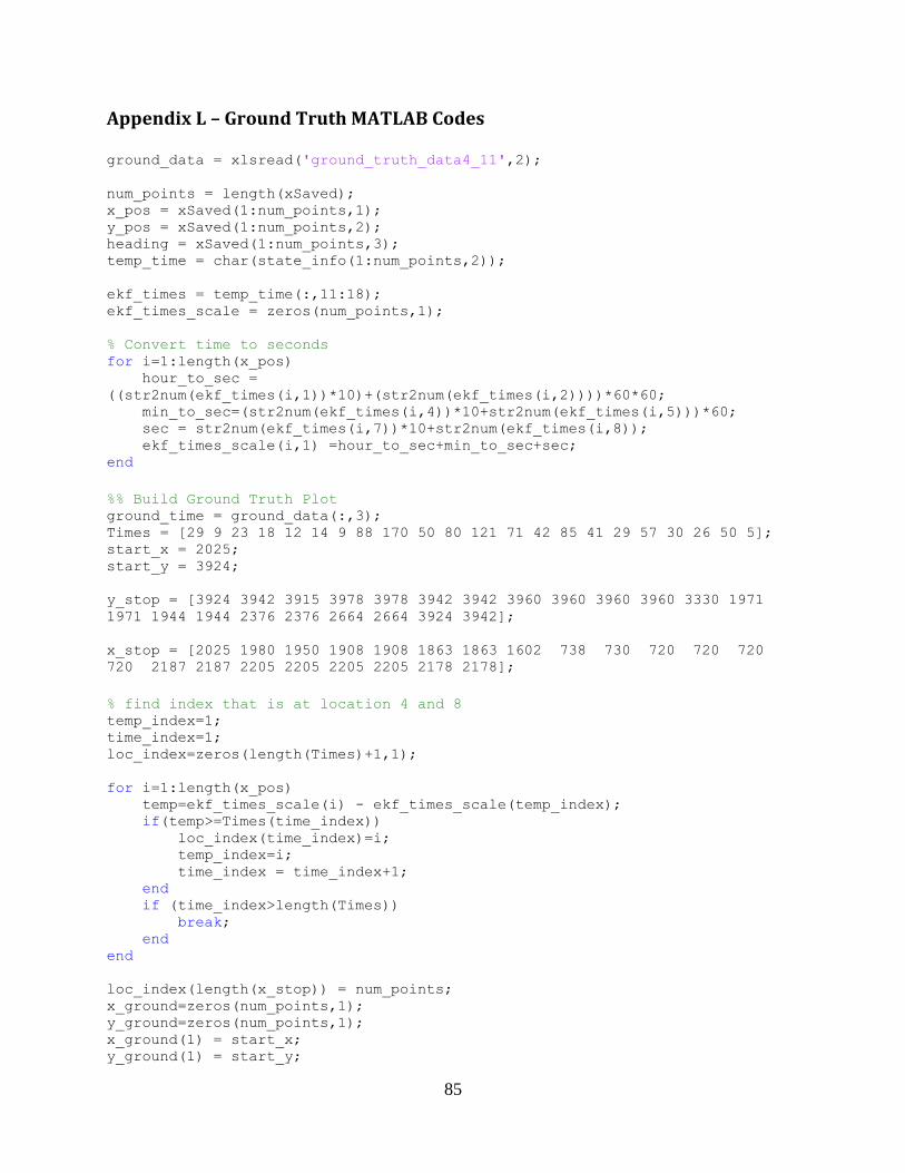
85
Appendix L – Ground Truth MATLAB Codes
ground_data = xlsread('ground_truth_data4_11',2);
num_points = length(xSaved); x_pos = xSaved(1:num_points,1); y_pos = xSaved(1:num_points,2); heading = xSaved(1:num_points,3); temp_time = char(state_info(1:num_points,2));
ekf_times = temp_time(:,11:18); ekf_times_scale = zeros(num_points,1);
% Convert time to seconds for i=1:length(x_pos) hour_to_sec =
((str2num(ekf_times(i,1))*10)+(str2num(ekf_times(i,2))))*60*60; min_to_sec=(str2num(ekf_times(i,4))*10+str2num(ekf_times(i,5)))*60; sec = str2num(ekf_times(i,7))*10+str2num(ekf_times(i,8)); ekf_times_scale(i,1) =hour_to_sec+min_to_sec+sec; end
%% Build Ground Truth Plot ground_time = ground_data(:,3); Times = [29 9 23 18 12 14 9 88 170 50 80 121 71 42 85 41 29 57 30 26 50 5]; start_x = 2025; start_y = 3924;
y_stop = [3924 3942 3915 3978 3978 3942 3942 3960 3960 3960 3960 3330 1971
1971 1944 1944 2376 2376 2664 2664 3924 3942];
x_stop = [2025 1980 1950 1908 1908 1863 1863 1602 738 730 720 720 720
720 2187 2187 2205 2205 2205 2205 2178 2178];
% find index that is at location 4 and 8 temp_index=1; time_index=1; loc_index=zeros(length(Times)+1,1);
for i=1:length(x_pos) temp=ekf_times_scale(i) - ekf_times_scale(temp_index); if(temp>=Times(time_index)) loc_index(time_index)=i; temp_index=i; time_index = time_index+1; end if (time_index>length(Times)) break; end end
loc_index(length(x_stop)) = num_points; x_ground=zeros(num_points,1); y_ground=zeros(num_points,1); x_ground(1) = start_x; y_ground(1) = start_y;

86
% store stop locations in ground truth for i=1:length(x_stop) x_ground(loc_index(i)) = x_stop(i); y_ground(loc_index(i)) = y_stop(i); end
for i=1:length(x_stop) if (i == 1) x_diff = x_ground(loc_index(i))-x_ground(1); y_diff = y_ground(loc_index(i))-y_ground(1); startp = 2; endp = loc_index(i) - 1; diff_points = endp-startp; else x_diff = x_ground(loc_index(i))-x_ground(loc_index(i-1)); y_diff = y_ground(loc_index(i))-y_ground(loc_index(i-1)); startp = loc_index(i-1) + 1; endp = loc_index(i) - 1; diff_points = endp - startp; end for a=1:diff_points+1 x_step = x_diff/diff_points; y_step = y_diff/diff_points; x_ground(startp-1+a) = x_ground(startp-2+a)+x_step; y_ground(startp-1+a) = y_ground(startp-2+a)+y_step; end end

87
Appendix M – Get IMU Data MATLAB Codes
% Get_Real_Time_Data.m % This function reads one sample of data from the IMU. % Modified Version of MT_Easy_Script
function inertialData = Get_IMU_Data
if(exist('h') == 0) % Creates the server h=actxserver('MotionTracker.CMT'); % Create a CMT instance serial = '43206-40120-9E20D-B4A57'; h.cmtCreateInstance(serial); % Set Parameters COMport = 6; baudrate = 115200; % Opens port for IMU h.cmtOpenPort(COMport,baudrate); % Checks to see if MTx is connected [num_MTs]= h.cmtGetMtCount(); if num_MTs==0, error('MTx not connected') end % request device information from MotionTracker [deviceId] = h.cmtGetMtDeviceId(0); dec2hex(deviceId); % Put MotionTracker in config mode h.cmtGotoConfig(); [heading] = 0; [location] = 0; [samplefreq] = 100; % request calibrated inertial and magnetic data along with orientation data h.cmtSetDeviceMode(6, 5, samplefreq, deviceId) % Orientation outputmode,
sample counter+euler, 100 Hz % That's it! % CMT is ready to start processing the data stream from the MotionTracker h.cmtGotoMeasurement(); % start processing data end % wait short moment for object to read data from COM-port pause(0.1); % let CMT get next data bundle h.cmtGetNextDataBundle(); % retrieve the data [inertialData] = h.cmtDataGetCalData(deviceId); % get latest calibrated data
from buffer [eulerAngle] = h.cmtDataGetOriEuler(deviceId); % get latest orientation data
from buffer inertialData = double(inertialData); % data values (can be converted to
double for easy use in Matlab) eulerAngle = double(eulerAngle) ;% data values (can be converted to double
for easy use in Matlab) disp(inertialData);
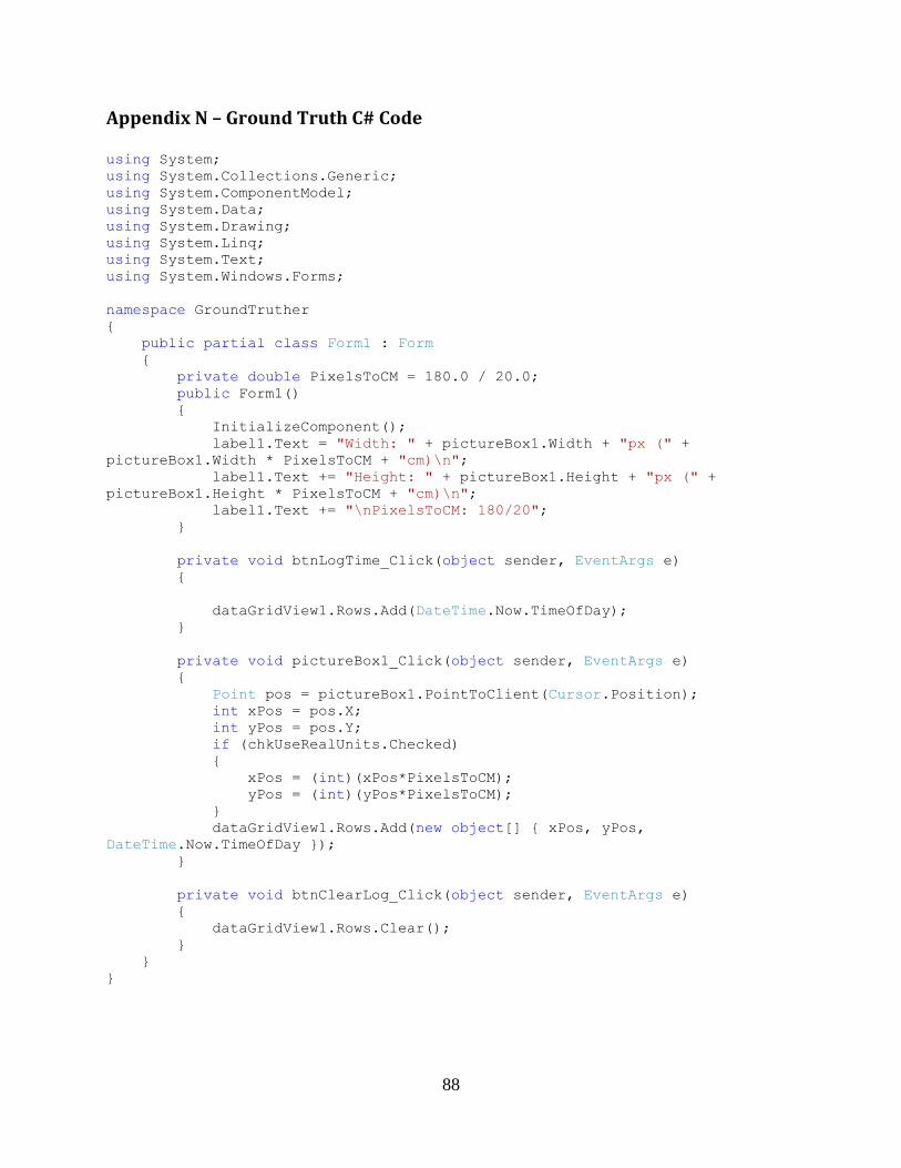
88
Appendix N – Ground Truth C# Code
using System;
using System.Collections.Generic;
using System.ComponentModel;
using System.Data;
using System.Drawing;
using System.Linq;
using System.Text;
using System.Windows.Forms;
namespace GroundTruther
{
public partial class Form1 : Form
{
private double PixelsToCM = 180.0 / 20.0;
public Form1()
{
InitializeComponent();
label1.Text = "Width: " + pictureBox1.Width + "px (" +
pictureBox1.Width * PixelsToCM + "cm)\n";
label1.Text += "Height: " + pictureBox1.Height + "px (" +
pictureBox1.Height * PixelsToCM + "cm)\n";
label1.Text += "\nPixelsToCM: 180/20";
}
private void btnLogTime_Click(object sender, EventArgs e)
{
dataGridView1.Rows.Add(DateTime.Now.TimeOfDay);
}
private void pictureBox1_Click(object sender, EventArgs e)
{
Point pos = pictureBox1.PointToClient(Cursor.Position);
int xPos = pos.X;
int yPos = pos.Y;
if (chkUseRealUnits.Checked)
{
xPos = (int)(xPos*PixelsToCM);
yPos = (int)(yPos*PixelsToCM);
}
dataGridView1.Rows.Add(new object[] { xPos, yPos,
DateTime.Now.TimeOfDay });
}
private void btnClearLog_Click(object sender, EventArgs e)
{
dataGridView1.Rows.Clear();
}
}
}
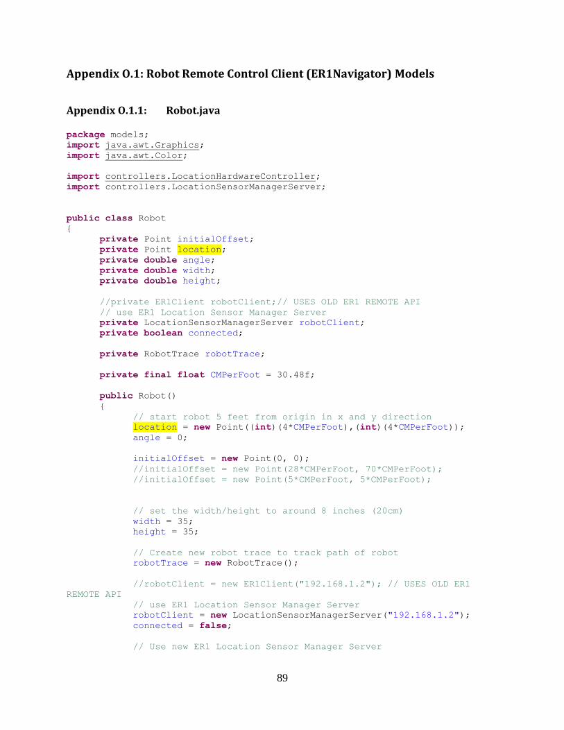
89
Appendix O.1: Robot Remote Control Client (ER1Navigator) Models
Appendix O.1.1: Robot.java
package models;
import java.awt.Graphics;
import java.awt.Color;
import controllers.LocationHardwareController;
import controllers.LocationSensorManagerServer;
public class Robot
{
private Point initialOffset;
private Point location;
private double angle;
private double width;
private double height;
//private ER1Client robotClient;// USES OLD ER1 REMOTE API
// use ER1 Location Sensor Manager Server
private LocationSensorManagerServer robotClient;
private boolean connected;
private RobotTrace robotTrace;
private final float CMPerFoot = 30.48f;
public Robot()
{
// start robot 5 feet from origin in x and y direction
location = new Point((int)(4*CMPerFoot),(int)(4*CMPerFoot));
angle = 0;
initialOffset = new Point(0, 0);
//initialOffset = new Point(28*CMPerFoot, 70*CMPerFoot);
//initialOffset = new Point(5*CMPerFoot, 5*CMPerFoot);
// set the width/height to around 8 inches (20cm)
width = 35;
height = 35;
// Create new robot trace to track path of robot
robotTrace = new RobotTrace();
//robotClient = new ER1Client("192.168.1.2"); // USES OLD ER1
REMOTE API
// use ER1 Location Sensor Manager Server
robotClient = new LocationSensorManagerServer("192.168.1.2");
connected = false;
// Use new ER1 Location Sensor Manager Server
90
}
/* REMOVING OLD ER1Client
public ER1Client getClient()
*/
public LocationSensorManagerServer getClient()
{
return robotClient;
}
public RobotTrace getTrace()
{
return robotTrace;
}
public boolean connected()
{
return connected;
}
public boolean connect(String ipAddress)
{
robotClient.setIPAdress(ipAddress);
connected = robotClient.Connected();
return connected;
}
/* REMOVING OLD ER1Client
public boolean connect()
{
connected = robotClient.connect();
return connected;
}
public void disconnect()
{
robotClient.disconnect();
connected = false;
}
*/
public double getWidth()
{
return width;
}
public double getHeight()
{
return height;
}
public Point getLocation()
{
return location;
}
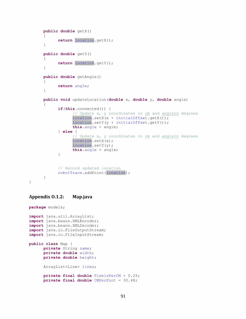
91
public double getX()
{
return location.getX();
}
public double getY()
{
return location.getY();
}
public double getAngle()
{
return angle;
}
public void updateLocation(double x, double y, double angle)
{
if(this.connected()) {
// Update x, y coordinates in cm and anglein degrees
location.setX(x + initialOffset.getX());
location.setY(y + initialOffset.getY());
this.angle = angle;
} else {
// Update x, y coordinates in cm and anglein degrees
location.setX(x);
location.setY(y);
this.angle = angle;
}
// Record updated location
robotTrace.addPoint(location);
}
}
Appendix O.1.2: Map.java
package models;
import java.util.ArrayList;
import java.beans.XMLEncoder;
import java.beans.XMLDecoder;
import java.io.FileOutputStream;
import java.io.FileInputStream;
public class Map {
private String name;
private double width;
private double height;
ArrayList<Line> lines;
private final double PixelsPerCM = 0.25;
private final double CMPerFoot = 30.48;
92
public Map()
{
name = "";
width = 800;
height = 600;
lines = new ArrayList<Line>();
loadTestMap();
}
public void loadTestMap()
{
// set canvis size
this.width = 62*CMPerFoot;
this.height = 80*CMPerFoot;
// outer map
addLineInFeet(1, 1, 61, 1);
addLineInFeet(1, 79, 61, 79);
addLineInFeet(1, 1, 1, 79);
addLineInFeet(61, 1, 61, 79);
addLineInFeet(7, 7, 55, 7);
addLineInFeet(7, 73, 55, 73);
addLineInFeet(7, 7, 7, 73);
addLineInFeet(55, 7, 55, 73);
}
public Map(Map map)
{
this.name = map.name;
this.width = map.width;
this.height = map.height;
this.lines = (ArrayList<Line>)map.lines.clone();
}
public double getWidth()
{
return width;
}
public double getHeight()
{
return height;
}
public String getName()
{
return name;
}
public void setName(String name)
{
this.name = name;
}
public void addLine(Line line)
93
{
lines.add(line);
}
private int feetToPixels(float feet)
{
return (int) (feet * CMPerFoot * PixelsPerCM);
}
/**
* Adds a line to the map params in unit of cm
* @param x1 cm
* @param y1 cm
* @param x2 cm
* @param y2 cm
*/
public void addLine(double x1, double y1, double x2, double y2)
{
lines.add(new Line(x1, y1, x2, y2));
}
/**
* Adds a line to the map params in unit of feet
* @param x1 Feet
* @param y1 Feet
* @param x2 Feet
* @param y2 Feet
*/
public void addLineInFeet(double x1, double y1, double x2, double y2)
{
lines.add(new Line(x1*CMPerFoot, y1*CMPerFoot, x2*CMPerFoot,
y2*CMPerFoot));
}
public ArrayList<Line> getLines()
{
return lines;
}
// FileWriting
//http://www.rgagnon.com/javadetails/java-0470.html
public boolean writeFile(String filename)
{
// Create output stream
FileOutputStream fos = null;
try{
fos = new FileOutputStream(filename);
} catch(Exception e) {
return false;
}
// Create XML encoder.
XMLEncoder xenc = new XMLEncoder(fos);
// Write object;
xenc.writeObject(new Map(this));
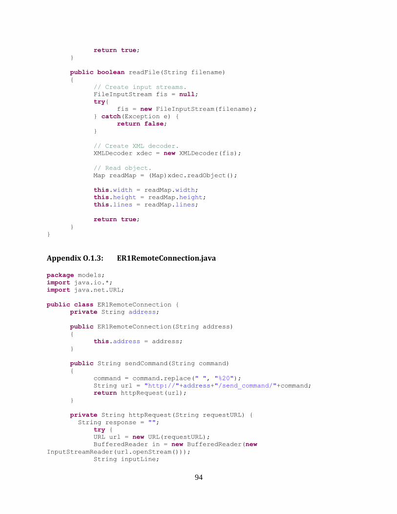
94
return true;
}
public boolean readFile(String filename)
{
// Create input streams.
FileInputStream fis = null;
try{
fis = new FileInputStream(filename);
} catch(Exception e) {
return false;
}
// Create XML decoder.
XMLDecoder xdec = new XMLDecoder(fis);
// Read object.
Map readMap = (Map)xdec.readObject();
this.width = readMap.width;
this.height = readMap.height;
this.lines = readMap.lines;
return true;
}
}
Appendix O.1.3: ER1RemoteConnection.java
package models;
import java.io.*;
import java.net.URL;
public class ER1RemoteConnection {
private String address;
public ER1RemoteConnection(String address)
{
this.address = address;
}
public String sendCommand(String command)
{
command = command.replace(" ", "%20");
String url = "http://"+address+"/send_command/"+command;
return httpRequest(url);
}
private String httpRequest(String requestURL) {
String response = "";
try {
URL url = new URL(requestURL);
BufferedReader in = new BufferedReader(new
InputStreamReader(url.openStream()));
String inputLine;
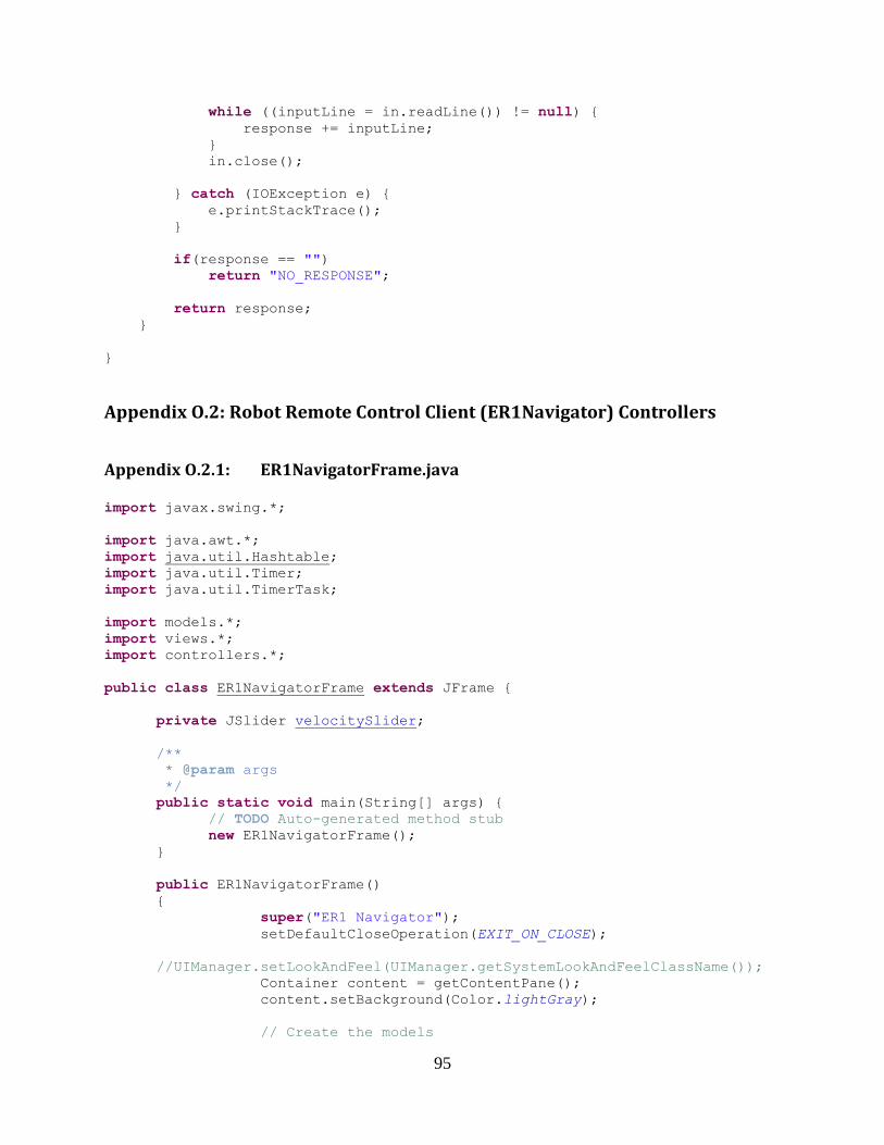
95
while ((inputLine = in.readLine()) != null) {
response += inputLine;
}
in.close();
} catch (IOException e) {
e.printStackTrace();
}
if(response == "")
return "NO_RESPONSE";
return response;
}
}
Appendix O.2: Robot Remote Control Client (ER1Navigator) Controllers
Appendix O.2.1: ER1NavigatorFrame.java
import javax.swing.*;
import java.awt.*;
import java.util.Hashtable;
import java.util.Timer;
import java.util.TimerTask;
import models.*;
import views.*;
import controllers.*;
public class ER1NavigatorFrame extends JFrame {
private JSlider velocitySlider;
/**
* @param args
*/
public static void main(String[] args) {
// TODO Auto-generated method stub
new ER1NavigatorFrame();
}
public ER1NavigatorFrame()
{
super("ER1 Navigator");
setDefaultCloseOperation(EXIT_ON_CLOSE);
//UIManager.setLookAndFeel(UIManager.getSystemLookAndFeelClassName());
Container content = getContentPane();
content.setBackground(Color.lightGray);
// Create the models
96
models.Robot robot = new models.Robot();
Map map = new Map();
// Create the controllers
LoggerController logger = new LoggerController();
MoveController moveController = new MoveController(robot);
MapController mapController = new MapController();
// Create the views
MapPanel mapPanel = new MapPanel(map, robot ,
mapController);
ConnectionPanel connectionPanel = new
ConnectionPanel(robot);
CommandPanel commandPanel = new CommandPanel(robot);
ControlPanel controlPanel = new
ControlPanel(moveController);
LoggerPanel loggerPanel = new LoggerPanel(robot, logger);
// Create the tabbed pane of views
JTabbedPane tabPane = new JTabbedPane();
tabPane.addTab("Connection", connectionPanel);
tabPane.addTab("Command", commandPanel);
tabPane.addTab("Control", controlPanel);
tabPane.addTab("Logging", loggerPanel);
// Add MapPanel to left half side of the screen and the
TabbedPane to the right half side
JPanel mainArea = new JPanel(new GridLayout(1,3));
JPanel mapArea = new JPanel();
mapArea.setLayout(new BoxLayout(mapArea,
BoxLayout.Y_AXIS));
JSlider zoomSlider = mapPanel.getZoomSlider();
JCheckBox detailView = mapPanel.getDetailView();
mapArea.add(zoomSlider);
mapArea.add(detailView);
mapArea.add(mapPanel.getHeadingLabel());
mapArea.add(mapPanel);
mainArea.add(mapArea);
mainArea.add(tabPane);
content.add(mainArea);
setSize(1024, 768);
setVisible(true);
// Update Robots Location every second using ER1 Control
Panel
TimerTask robotLocationController = new
RobotLocationController(robot, mapPanel, logger);
Timer timer = new Timer();
timer.schedule(robotLocationController, 0, 1000);
}
}
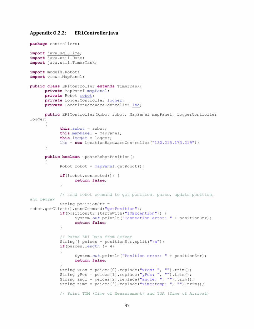
97
Appendix O.2.2: ER1Controller.java
package controllers;
import java.sql.Time;
import java.util.Date;
import java.util.TimerTask;
import models.Robot;
import views.MapPanel;
public class ER1Controller extends TimerTask{
private MapPanel mapPanel;
private Robot robot;
private LoggerController logger;
private LocationHardwareController lhc;
public ER1Controller(Robot robot, MapPanel mapPanel, LoggerController
logger)
{
this.robot = robot;
this.mapPanel = mapPanel;
this.logger = logger;
lhc = new LocationHardwareController("130.215.173.219");
}
public boolean updateRobotPosition()
{
Robot robot = mapPanel.getRobot();
if(!robot.connected()) {
return false;
}
// send robot command to get position, parse, update position,
and redraw
String positionStr =
robot.getClient().sendCommand("getPosition");
if(positionStr.startsWith("IOException")) {
System.out.println("Connection error: " + positionStr);
return false;
}
// Parse ER1 Data from Server
String[] peices = positionStr.split("\n");
if(peices.length != 4)
{
System.out.println("Position error: " + positionStr);
return false;
}
String xPos = peices[0].replace("xPos: ", "").trim();
String yPos = peices[1].replace("yPos: ", "").trim();
String angl = peices[2].replace("angle: ", "").trim();
String time = peices[3].replace("Timestamp: ", "").trim();
// Print TOM (Time of Measurement) and TOA (Time of Arrival)
98
Date toa = new Date();
System.out.println("TOM: " + time + "\t TOA: " + toa);
double x = Double.parseDouble(xPos); // in units of cm
double y = Double.parseDouble(yPos); // in units of cm
double angle = Double.parseDouble(angl); // in units of degrees
robot.updateLocation(x, y, angle);
// Position Logging
if(logger.isLogging())
logger.logLocation(x, y, angle);
return true;
}
@Override
public void run() {
// TODO Auto-generated method stub
updateRobotPosition();
mapPanel.repaint();
}
}
Appendix O.2.3: MapController.java
package controllers;
import javax.swing.JSlider;
import javax.swing.event.ChangeEvent;
import javax.swing.event.ChangeListener;
import views.*;
public class MapController implements ChangeListener {
private MapView mapView;
private RobotView robotView;
private static final int ZOOM_MIN = 0;
private static final int ZOOM_MAX = 100;
private static final int ZOOM_INIT = 25;
public MapController()
{
this.mapView = null;
this.robotView = null;
}
public void setMapView(MapView mapView)
{
this.mapView = mapView;
}
public void setRobotView(RobotView robotView)
{
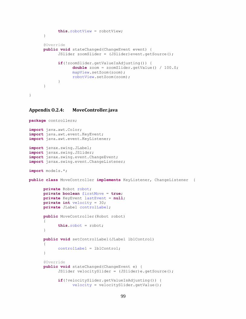
99
this.robotView = robotView;
}
@Override
public void stateChanged(ChangeEvent event) {
JSlider zoomSlider = (JSlider)event.getSource();
if(!zoomSlider.getValueIsAdjusting()) {
double zoom = zoomSlider.getValue() / 100.0;
mapView.setZoom(zoom);
robotView.setZoom(zoom);
}
}
}
Appendix O.2.4: MoveController.java
package controllers;
import java.awt.Color;
import java.awt.event.KeyEvent;
import java.awt.event.KeyListener;
import javax.swing.JLabel;
import javax.swing.JSlider;
import javax.swing.event.ChangeEvent;
import javax.swing.event.ChangeListener;
import models.*;
public class MoveController implements KeyListener, ChangeListener {
private Robot robot;
private boolean firstMove = true;
private KeyEvent lastEvent = null;
private int velocity = 30;
private JLabel controlLabel;
public MoveController(Robot robot)
{
this.robot = robot;
}
public void setControlLabel(JLabel lblControl)
{
controlLabel = lblControl;
}
@Override
public void stateChanged(ChangeEvent e) {
JSlider velocitySlider = (JSlider)e.getSource();
if(!velocitySlider.getValueIsAdjusting()) {
velocity = velocitySlider.getValue();
100
try {
robot.getClient().sendCommand("set v
"+velocity+"\n");
} catch (Exception e1) {
// TODO Auto-generated catch block
//e1.printStackTrace();
}
}
}
@Override
public void keyPressed(KeyEvent event) {
if(!robot.connected()) {
updateControlLabel(false, "No Connection to ER1");
return;
}
if(lastEvent != null && lastEvent.getKeyCode() ==
event.getKeyCode())
return;
lastEvent = event;
switch(event.getKeyCode())
{
case KeyEvent.VK_UP: upPressed(); break;
case KeyEvent.VK_DOWN: downPressed(); break;
case KeyEvent.VK_LEFT: leftPressed(); break;
case KeyEvent.VK_RIGHT: rightPressed(); break;
default: updateControlLabel(true); break;
}
}
@Override
public void keyReleased(KeyEvent arg0) {
if(!robot.connected()) {
updateControlLabel(false, "No Connection to ER1");
return;
}
lastEvent = null;
switch(arg0.getKeyCode())
{
case KeyEvent.VK_UP: upReleased(); break;
case KeyEvent.VK_DOWN: downReleased(); break;
case KeyEvent.VK_LEFT: leftReleased(); break;
case KeyEvent.VK_RIGHT: rightReleased(); break;
}
updateControlLabel(true); // Clear movement from control label
}
@Override
public void keyTyped(KeyEvent arg0) {
// TODO Auto-generated method stub
}
public void upPressed()
{
101
updateControlLabel(true, "Moving Forward");
System.out.println("move forward");
if(robot.connected())
{
String recMsg;
String doneString;
boolean moveDone = false;
if(!firstMove)
{
try {
Thread.sleep(100);
} catch (InterruptedException e) {
// TODO Auto-generated catch block
e.printStackTrace();
}
System.out.println("Checking if Move Done");
recMsg = robot.getClient().sendCommand("events\n");
doneString = "move done";
moveDone = (recMsg.indexOf(doneString) >= 0);
}
if(moveDone || firstMove)
{
if(firstMove)
System.out.println("First Move sending
command");
if(moveDone)
System.out.println("Last Move Done but move key
still pressed... resending move command");
robot.getClient().sendCommand("move 50000 cm\n");
firstMove = false;
}
}
else {
System.out.println("Error Moving: Robot is not
connected...");
//robot.updateLocation(robot.getLocation().getX()+20,
robot.getLocation().getY(), robot.getAngle());
}
}
public void upReleased()
{
System.out.println("stop move forward\n");
if(robot.connected())
{
robot.getClient().sendCommand("stop\n");
} else {
System.out.println("UpReleased: STOP MOVNG FAILED");
}
firstMove = true;
}
public void downPressed()
{
102
updateControlLabel(true, "Moving Backwards");
System.out.println("move backword");
if(robot.connected())
{
if(firstMove)
{
robot.getClient().sendCommand("move -500000 cm\n");
firstMove = false;
}
}
else {
System.out.println("Error Moving: Robot is not
connected...");
//robot.updateLocation(robot.getLocation().getX()-20,
robot.getLocation().getY(), robot.getAngle());
}
}
public void downReleased()
{
System.out.println("stop move forward\n");
if(robot.connected())
{
robot.getClient().sendCommand("stop\n");
}
firstMove = true;
}
public void leftPressed()
{
updateControlLabel(true, "Turning Left");
System.out.println("turn left\n");
if(robot.connected())
{
robot.getClient().sendCommand("move 360 d\n");
}
else {
System.out.println("Error Moving: Robot is not
connected...");
//robot.updateLocation(robot.getLocation().getX(),
robot.getLocation().getY()-20, robot.getAngle());
}
}
public void leftReleased()
{
System.out.println("stop turn left\n");
if(robot.connected())
{
robot.getClient().sendCommand("stop\n");
}
}
public void rightPressed()
{
updateControlLabel(true, "Turning Right");
System.out.println("turn right\n");
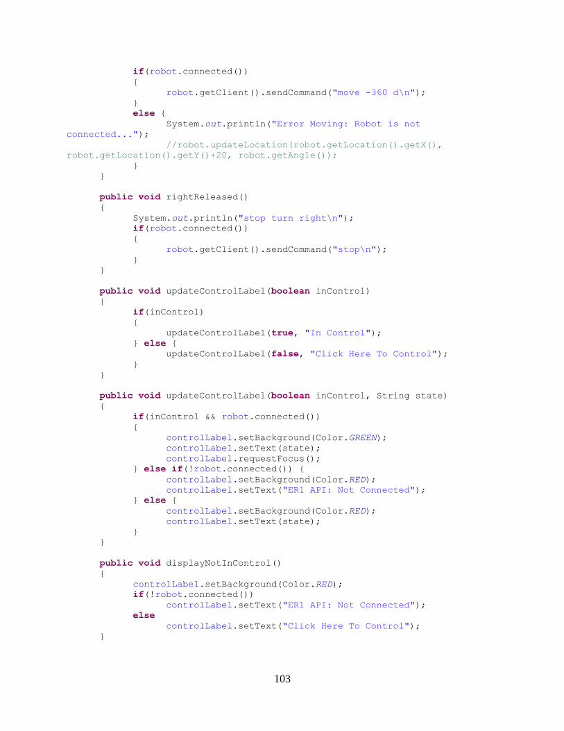
103
if(robot.connected())
{
robot.getClient().sendCommand("move -360 d\n");
}
else {
System.out.println("Error Moving: Robot is not
connected...");
//robot.updateLocation(robot.getLocation().getX(),
robot.getLocation().getY()+20, robot.getAngle());
}
}
public void rightReleased()
{
System.out.println("stop turn right\n");
if(robot.connected())
{
robot.getClient().sendCommand("stop\n");
}
}
public void updateControlLabel(boolean inControl)
{
if(inControl)
{
updateControlLabel(true, "In Control");
} else {
updateControlLabel(false, "Click Here To Control");
}
}
public void updateControlLabel(boolean inControl, String state)
{
if(inControl && robot.connected())
{
controlLabel.setBackground(Color.GREEN);
controlLabel.setText(state);
controlLabel.requestFocus();
} else if(!robot.connected()) {
controlLabel.setBackground(Color.RED);
controlLabel.setText("ER1 API: Not Connected");
} else {
controlLabel.setBackground(Color.RED);
controlLabel.setText(state);
}
}
public void displayNotInControl()
{
controlLabel.setBackground(Color.RED);
if(!robot.connected())
controlLabel.setText("ER1 API: Not Connected");
else
controlLabel.setText("Click Here To Control");
}

104
}
Appendix O.2.5: RobotLocationController.java
package controllers;
import java.util.ArrayList;
import java.util.TimerTask;
import models.*;
import views.*;
public class RobotLocationController extends TimerTask {
private MapPanel mapPanel;
private Robot robot;
private LoggerController logger;
public RobotLocationController(Robot robot, MapPanel mapPanel,
LoggerController logger)
{
this.robot = robot;
this.mapPanel = mapPanel;
this.logger = logger;
}
public boolean connected()
{
if(!robot.connected()) return false;
/*
String resp = robot.getClient().sendCommand("isER1Connected");
resp.trim();
if(resp.startsWith("CONNECTED")) return true;
return false;
*/
return true;
}
public boolean updateRobotPosition()
{
Robot robot = mapPanel.getRobot();
// Make sure we are connected to both the:
// remote location sensor manager server
// and the ER1 Remote API
if(!this.connected()) {
return false;
}
/* USING OLD TELNET DIRECT CONNECTION TO ER1 REMOTE TELNET API */
// NEW API MIMICS OLD SO SAME CODE WORKS
105
// otherwise the robot is connected so
// send robot command to get position, parse, update position,
and redraw
//robot.getClient().sendCommand("move -10 c\n");
//robot.getClient().waitFor("move\n");
String positionStr =
robot.getClient().sendCommand("getEKFPosition");//customPosition\n");
if(positionStr.split(" ").length != 4)
{
System.out.println("Position error: " + positionStr);
return false;
}
double x = 0, y = 0, angle = 0;
try {
x = Double.parseDouble(positionStr.split(" ")[1]); // in units
of cm
y = Double.parseDouble(positionStr.split(" ")[2]); // in units
of cm
angle = Double.parseDouble(positionStr.split(" ")[3]); // in
units of degrees
} catch(Exception e) {
System.out.println("Position error extracting: " +
positionStr);
}
robot.updateLocation(x, y, angle);
// Position Logging
if(logger.isLogging())
logger.logLocation(x, y, angle);
return true;
}
@Override
public void run() {
// TODO Auto-generated method stub
updateRobotPosition();
mapPanel.repaint();
}
}
Appendix O.2.6: LoggerController.java
package controllers;
import java.io.File;
import java.security.Timestamp;
import java.sql.Time;
import java.util.ArrayList;
import javax.swing.JTextArea;
106
import models.*;
public class LoggerController {
private File file;
private boolean logging;
// private boolean replay;
private JTextArea txtLogArea;
private ArrayList<PositionLog> robotLog;
public LoggerController()
{
file = null;
logging = false;
// replay = false;
txtLogArea = null;
robotLog = new ArrayList<PositionLog>();
}
public ArrayList<PositionLog> getPositionLog()
{
return robotLog;
}
public boolean isLogging()
{
return logging;
}
public void clearLog()
{
robotLog.clear();
if(txtLogArea != null)
txtLogArea.setText("X\tY\tangle\ttime\tvelocity\n");
}
public void startLogging()
{
// stopReplay();
logging = true;
clearLog();
}
public void stopLogging()
{
logging = false;
}
/*
public boolean isReplay()

107
{
return replay;
}
public void startReplay()
{
replay = true;
stopLogging();
}
public void stopReplay()
{
replay = false;
}
public void logPosition(Point location)
{
robotTrace.addPoint(location);
}
*/
public void logLocation(double x, double y, double angle)
{
// Get current timestamp
java.util.Date today = new java.util.Date();
Time now = new Time(today.getTime());
PositionLog curPos = new PositionLog(x, y, angle, now);
PositionLog lastPos = null;
if(robotLog.size() > 0)
lastPos = robotLog.get(robotLog.size()-1);
// log x, y, angle, and timestamp
if(isLogging() && txtLogArea != null)
{
txtLogArea.append(curPos.toString() + "\t" +
PositionLog.calcVelocity(lastPos, curPos) + "cm/s "+ "\n");
robotLog.add(curPos);
}
}
public void setLogArea(JTextArea txtLogArea)
{
this.txtLogArea = txtLogArea;
}
}
Appendix O.3: Robot Remote Control Client (ER1Navigator) Views
Appendix O.3.1: CameraPanel.java
package views;
108
import java.awt.*;
import java.awt.image.BufferedImage;
import java.net.MalformedURLException;
import java.net.URL;
import java.util.*;
import java.util.Timer;
import javax.swing.*;
public class CameraPanel extends JPanel {
Image img;
Image lastImg;
Timer timer;
int interval; // interval to update frames in milliseconds
String ipAddress = "130.215.172.134:8888"; // = "localhost:8888";
CameraPanel ()
{
this.interval = 500;
this.img =
Toolkit.getDefaultToolkit().createImage("http://"+ipAddress+"/current.jpg");
this.timer = new Timer();
timer.schedule(new FrameGrabTask(this), this.interval);
}
class FrameGrabTask extends TimerTask {
CameraPanel cp;
public FrameGrabTask(CameraPanel cp) { this.cp = cp; }
public void run() {
URL url = null;
try {
url = new URL("http://"+ipAddress+"/current.jpg");
} catch (MalformedURLException e) {
// TODO Auto-generated catch block
e.printStackTrace();
}
Image img = Toolkit.getDefaultToolkit().createImage(url);
img.setAccelerationPriority(1);
MediaTracker mt = new MediaTracker(cp);
mt.addImage(img, 0);
try{
mt.waitForAll();
} catch(Exception ex) {
System.out.println(ex.getMessage());
}
mt.removeImage(img);
System.out.println("Update frame");
cp.timer.schedule(new FrameGrabTask(cp),cp.interval);
cp.updateFrame(img);

109
}
}
public void updateFrame(Image newImg)
{
this.img = newImg;
this.repaint();
//this.repaint();
//img.flush();
}
public void paint (Graphics g) {
super.paint (g);
this.setSize(this.img.getWidth(null), this.img.getHeight(null));
//Draw image centered in the middle of the panel
if(this.img != null)
g.drawImage (this.img, 10, 10, this);//imgX, imgY, this);
} // paintComponent
}
Appendix O.3.2: CommandPanel.java
package views;
import javax.swing.*;
import java.awt.event.*;
import java.awt.*;
import models.Robot;
public class CommandPanel extends JPanel {
private Robot robot;
private JLabel lblCommand;
private JLabel lblResponse;
private JTextField txtCommand;
private JTextField txtResponse;
private JButton btnSendCommand;
public CommandPanel(Robot robot)
{
this.robot = robot;
initializeComponents();
setVisible(true);
}
public void initializeComponents()
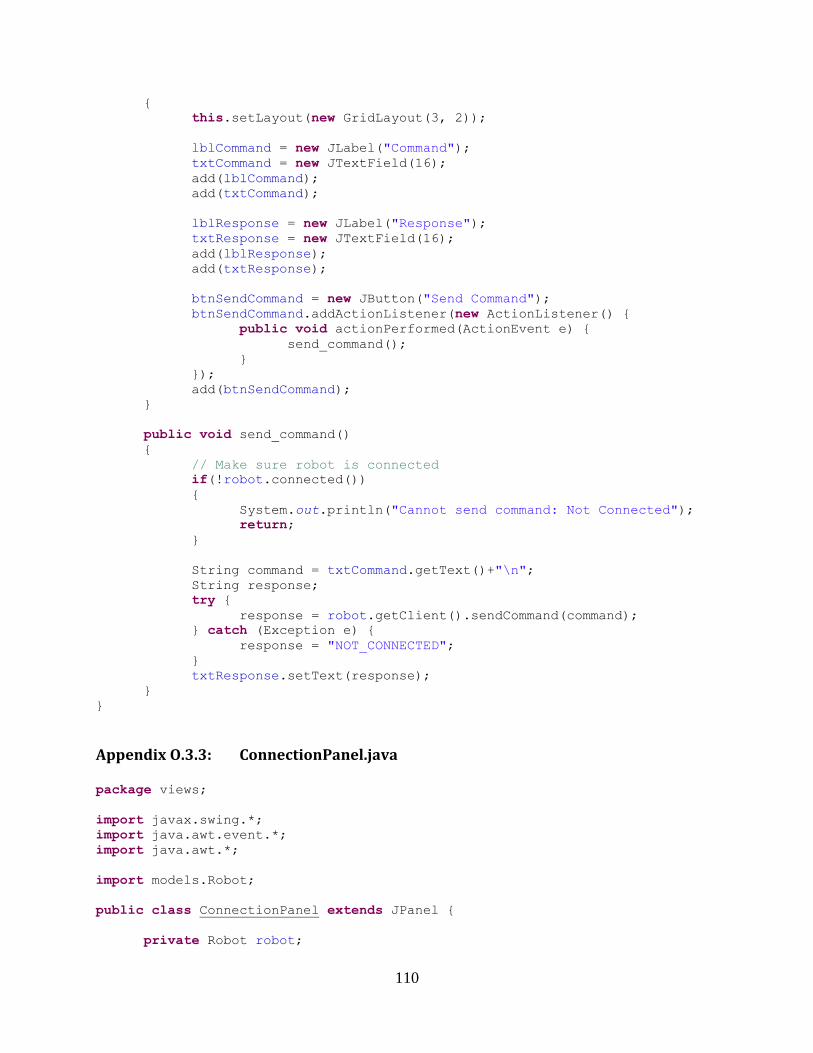
110
{
this.setLayout(new GridLayout(3, 2));
lblCommand = new JLabel("Command");
txtCommand = new JTextField(16);
add(lblCommand);
add(txtCommand);
lblResponse = new JLabel("Response");
txtResponse = new JTextField(16);
add(lblResponse);
add(txtResponse);
btnSendCommand = new JButton("Send Command");
btnSendCommand.addActionListener(new ActionListener() {
public void actionPerformed(ActionEvent e) {
send_command();
}
});
add(btnSendCommand);
}
public void send_command()
{
// Make sure robot is connected
if(!robot.connected())
{
System.out.println("Cannot send command: Not Connected");
return;
}
String command = txtCommand.getText()+"\n";
String response;
try {
response = robot.getClient().sendCommand(command);
} catch (Exception e) {
response = "NOT_CONNECTED";
}
txtResponse.setText(response);
}
}
Appendix O.3.3: ConnectionPanel.java
package views;
import javax.swing.*;
import java.awt.event.*;
import java.awt.*;
import models.Robot;
public class ConnectionPanel extends JPanel {
private Robot robot;

111
private JLabel lblStatus;
private JLabel lblAddress;
private JLabel lblPort;
private JTextField txtStatus;
private JTextField txtAddress;
private JTextField txtPort;
private JButton btnConnect;
private JTextArea txtExtendedStatus;
public ConnectionPanel(Robot robot)
{
this.robot = robot;
initializeComponents();
setVisible(true);
}
public void initializeComponents()
{
lblStatus = new JLabel("Status");
txtStatus = new JTextField(10);
txtStatus.setText("Not Connected");
this.setLayout(new GridLayout(4, 2));
add(lblStatus);
add(txtStatus);
lblAddress = new JLabel("Address");
txtAddress = new JTextField(10);
txtAddress.setText("127.0.0.1");
add(lblAddress);
add(txtAddress);
lblPort = new JLabel("Port");
txtPort = new JTextField(10);
txtPort.setText("9000");
add(lblPort);
add(txtPort);
btnConnect = new JButton("Connect");
btnConnect.addActionListener(new ActionListener() {
public void actionPerformed(ActionEvent e) {
connect();
}
});
add(btnConnect);
txtExtendedStatus = new JTextArea();
}
public void connect()
{
// Connect to user defined IP Address
if(robot.connect(txtAddress.getText()))
{
// update status
txtStatus.setText("Connected");

112
btnConnect.setText("Disconnect");
} else {
txtStatus.setText("Connection Failed");
btnConnect.setText("Connect");
return;
}
txtExtendedStatus.setText(robot.getClient().sendCommand("test"));
}
}
Appendix O.3.4: ControlPanel.java
package views;
import javax.swing.*;
import java.awt.event.*;
import java.awt.*;
import java.util.Hashtable;
import models.Robot;
import controllers.MoveController;
public class ControlPanel extends JPanel implements FocusListener,
MouseListener {
private MoveController moveController;
private JLabel lblVelocity;
private JSlider velocitySlider;
private JLabel controlLabel;
public ControlPanel(MoveController moveCtrl)
{
initializeComponents();
moveController = moveCtrl;
moveController.setControlLabel(controlLabel); // Handle
displaying key press / move controls / control state
velocitySlider.addChangeListener(moveController); // Handle
Velocity Changing
controlLabel.addKeyListener(moveController); // Handle Moving
Forward and Backwards and Turning Left and Right using Arrow Keys
setVisible(true);
}
public void initializeComponents()
{
this.setLayout(new GridLayout(4, 1));
// Create Velocity Label
lblVelocity = new JLabel("Velocity: ");
// Create the velocity slider
velocitySlider = new JSlider(JSlider.HORIZONTAL, 5, 50, 30);

113
velocitySlider.setMajorTickSpacing(10);
velocitySlider.setMinorTickSpacing(1);
velocitySlider.setPaintTicks(true);
Hashtable labelTable = new Hashtable();
labelTable.put( new Integer( 5 ), new JLabel("5 cm/s") );
labelTable.put( new Integer( 15 ), new JLabel("15 cm/s") );
labelTable.put( new Integer( 30 ), new JLabel("30 cm/s") );
labelTable.put( new Integer( 50), new JLabel("50 cm/s"));
velocitySlider.setLabelTable( labelTable
);velocitySlider.setPaintLabels(true);
// Create the Move Control
controlLabel = new JLabel("Click Here To Control",
JLabel.CENTER);
controlLabel.setOpaque(true);
controlLabel.setBackground(Color.RED);
controlLabel.setFocusable(true);
controlLabel.addFocusListener(this);
controlLabel.addMouseListener(this);
CameraPanel cp = new CameraPanel();
//cp.setSize(400, 400);
add(cp);
add(lblVelocity);
add(velocitySlider);
add(controlLabel);
}
@Override
public void focusGained(FocusEvent e) {
moveController.updateControlLabel(true);
}
@Override
public void focusLost(FocusEvent e) {
moveController.updateControlLabel(false);
}
@Override
public void mouseClicked(MouseEvent arg0) {
// TODO Auto-generated method stub
moveController.updateControlLabel(true);
}
@Override
public void mouseEntered(MouseEvent arg0) {
// TODO Auto-generated method stub
}
@Override
public void mouseExited(MouseEvent arg0) {
// TODO Auto-generated method stub
}
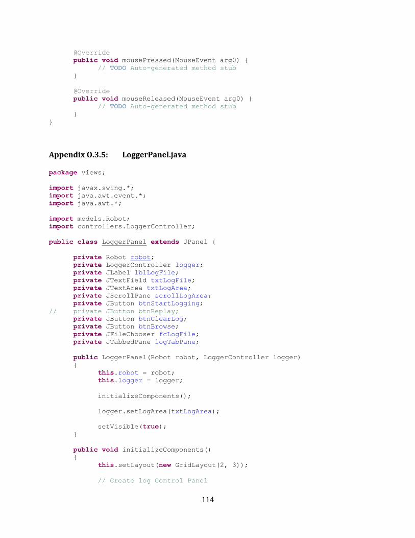
114
@Override
public void mousePressed(MouseEvent arg0) {
// TODO Auto-generated method stub
}
@Override
public void mouseReleased(MouseEvent arg0) {
// TODO Auto-generated method stub
}
}
Appendix O.3.5: LoggerPanel.java
package views;
import javax.swing.*;
import java.awt.event.*;
import java.awt.*;
import models.Robot;
import controllers.LoggerController;
public class LoggerPanel extends JPanel {
private Robot robot;
private LoggerController logger;
private JLabel lblLogFile;
private JTextField txtLogFile;
private JTextArea txtLogArea;
private JScrollPane scrollLogArea;
private JButton btnStartLogging;
// private JButton btnReplay;
private JButton btnClearLog;
private JButton btnBrowse;
private JFileChooser fcLogFile;
private JTabbedPane logTabPane;
public LoggerPanel(Robot robot, LoggerController logger)
{
this.robot = robot;
this.logger = logger;
initializeComponents();
logger.setLogArea(txtLogArea);
setVisible(true);
}
public void initializeComponents()
{
this.setLayout(new GridLayout(2, 3));
// Create log Control Panel

115
JPanel logControlPanel = new JPanel();
lblLogFile = new JLabel("Log File");
txtLogFile = new JTextField(32);
fcLogFile = new JFileChooser();
btnBrowse = new JButton("Browse");
btnBrowse.addActionListener(new ActionListener() {
public void actionPerformed(ActionEvent e) {
select_file();
}
});
logControlPanel.add(lblLogFile);
logControlPanel.add(txtLogFile);
logControlPanel.add(btnBrowse);
// Add Start Logging Button
btnStartLogging = new JButton("Start Logging");
btnStartLogging.addActionListener(new ActionListener() {
public void actionPerformed(ActionEvent e) {
start_logging();
}
});
logControlPanel.add(btnStartLogging);
/*
// Add Replay Button
btnReplay = new JButton("Replay");
btnReplay.addActionListener(new ActionListener() {
public void actionPerformed(ActionEvent e) {
start_replay();
}
});
logControlPanel.add(btnReplay);
*/
// Add Clear Log Button
btnClearLog = new JButton("Clear Log");
btnClearLog.addActionListener(new ActionListener() {
public void actionPerformed(ActionEvent e) {
clear_log();
}
});
logControlPanel.add(btnClearLog);
// Add Log Window
txtLogArea = new JTextArea();
scrollLogArea = new JScrollPane(txtLogArea);
// Add Log Pane
logTabPane = new JTabbedPane();
logTabPane.addTab("Log Control", logControlPanel);
logTabPane.addTab("ER1 Robot Log", scrollLogArea);
add(logTabPane);
}
116
public void select_file()
{
int result = fcLogFile.showSaveDialog(this);
if(result == JFileChooser.CANCEL_OPTION) return;
txtLogFile.setText(fcLogFile.getSelectedFile().getName());
}
public void clear_log()
{
logger.clearLog();
}
public void start_logging()
{
if(!logger.isLogging())
{
logger.startLogging();
btnStartLogging.setText("Stop Logging");
} else {
logger.stopLogging();
btnStartLogging.setText("Start Logging");
}
// update Replay button label
// updateReplayButtonLabel();
}
public void updateStartButtonLabel()
{
if(logger.isLogging())
{
btnStartLogging.setText("Stop Logging");
} else {
btnStartLogging.setText("Start Logging");
}
}
/*
public void start_replay()
{
if(!logger.isReplay())
{
logger.startReplay();
btnReplay.setText("Stop Replay");
} else {
logger.stopReplay();
btnReplay.setText("Start Replay");
}
// update start button
updateStartButtonLabel();
}
public void updateReplayButtonLabel()
{
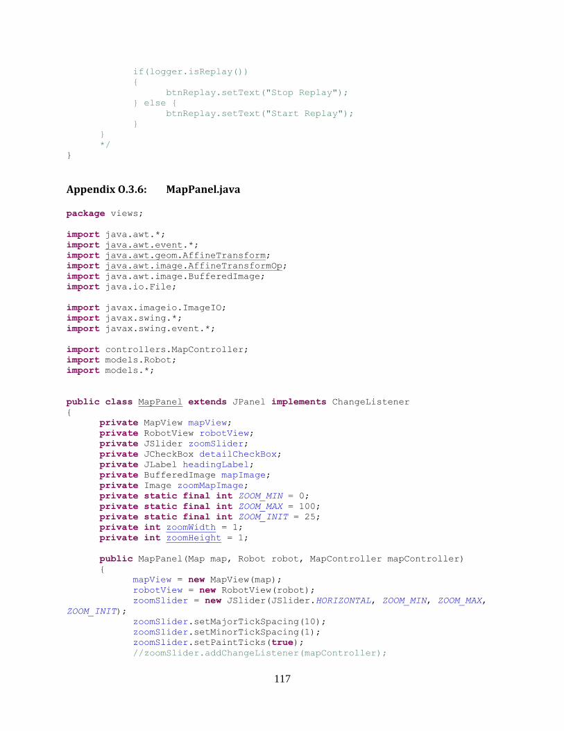
117
if(logger.isReplay())
{
btnReplay.setText("Stop Replay");
} else {
btnReplay.setText("Start Replay");
}
}
*/
}
Appendix O.3.6: MapPanel.java
package views;
import java.awt.*;
import java.awt.event.*;
import java.awt.geom.AffineTransform;
import java.awt.image.AffineTransformOp;
import java.awt.image.BufferedImage;
import java.io.File;
import javax.imageio.ImageIO;
import javax.swing.*;
import javax.swing.event.*;
import controllers.MapController;
import models.Robot;
import models.*;
public class MapPanel extends JPanel implements ChangeListener
{
private MapView mapView;
private RobotView robotView;
private JSlider zoomSlider;
private JCheckBox detailCheckBox;
private JLabel headingLabel;
private BufferedImage mapImage;
private Image zoomMapImage;
private static final int ZOOM_MIN = 0;
private static final int ZOOM_MAX = 100;
private static final int ZOOM_INIT = 25;
private int zoomWidth = 1;
private int zoomHeight = 1;
public MapPanel(Map map, Robot robot, MapController mapController)
{
mapView = new MapView(map);
robotView = new RobotView(robot);
zoomSlider = new JSlider(JSlider.HORIZONTAL, ZOOM_MIN, ZOOM_MAX,
ZOOM_INIT);
zoomSlider.setMajorTickSpacing(10);
zoomSlider.setMinorTickSpacing(1);
zoomSlider.setPaintTicks(true);
//zoomSlider.addChangeListener(mapController);
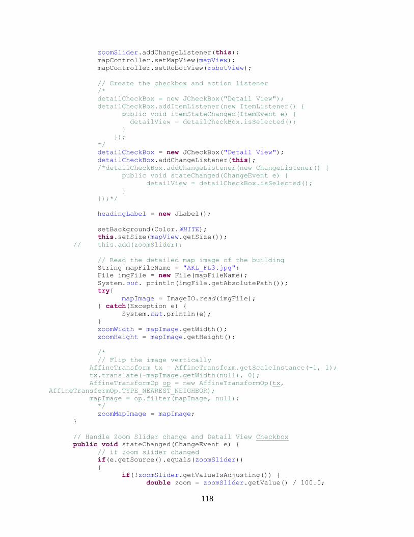
118
zoomSlider.addChangeListener(this);
mapController.setMapView(mapView);
mapController.setRobotView(robotView);
// Create the checkbox and action listener
/*
detailCheckBox = new JCheckBox("Detail View");
detailCheckBox.addItemListener(new ItemListener() {
public void itemStateChanged(ItemEvent e) {
detailView = detailCheckBox.isSelected();
}
});
*/
detailCheckBox = new JCheckBox("Detail View");
detailCheckBox.addChangeListener(this);
/*detailCheckBox.addChangeListener(new ChangeListener() {
public void stateChanged(ChangeEvent e) {
detailView = detailCheckBox.isSelected();
}
});*/
headingLabel = new JLabel();
setBackground(Color.WHITE);
this.setSize(mapView.getSize());
// this.add(zoomSlider);
// Read the detailed map image of the building
String mapFileName = "AKL_FL3.jpg";
File imgFile = new File(mapFileName);
System.out. println(imgFile.getAbsolutePath());
try{
mapImage = ImageIO.read(imgFile);
} catch(Exception e) {
System.out.println(e);
}
zoomWidth = mapImage.getWidth();
zoomHeight = mapImage.getHeight();
/*
// Flip the image vertically
AffineTransform tx = AffineTransform.getScaleInstance(-1, 1);
tx.translate(-mapImage.getWidth(null), 0);
AffineTransformOp op = new AffineTransformOp(tx,
AffineTransformOp.TYPE_NEAREST_NEIGHBOR);
mapImage = op.filter(mapImage, null);
*/
zoomMapImage = mapImage;
}
// Handle Zoom Slider change and Detail View Checkbox
public void stateChanged(ChangeEvent e) {
// if zoom slider changed
if(e.getSource().equals(zoomSlider))
{
if(!zoomSlider.getValueIsAdjusting()) {
double zoom = zoomSlider.getValue() / 100.0;

119
if(detailCheckBox.isSelected()) {
zoomMapImage = mapImage;
this.repaint();
double mapPixelsPerCM = 20.0/180.0; // 20
pixels for every 75 cm (unscaled)
robotView.setZoom(mapPixelsPerCM);
/*
// 25% zoom is no scaling of image
zoomWidth = (int)(4*zoom *
mapImage.getWidth());
zoomHeight = (int)(4*zoom *
mapImage.getHeight());
zoomMapImage =
mapImage.getScaledInstance(zoomWidth, zoomHeight, Image.SCALE_DEFAULT);
this.repaint();
double mapPixelsPerCM = 20.0/75.0; // 20 pixels
for every 75 cm (unscaled)
robotView.setZoom(4*zoom*mapPixelsPerCM);
*/
} else {
mapView.setZoom(zoom);
robotView.setZoom(zoom);
}
}
// if the detailed view checkbox is changed
} else if(e.getSource().equals((detailCheckBox))) {
this.repaint();
}
}
public JSlider getZoomSlider()
{
return zoomSlider;
}
public JCheckBox getDetailView()
{
return detailCheckBox;
}
public JLabel getHeadingLabel()
{
return headingLabel;
}
// Display the Map and the Robot's location
public void paintComponent(Graphics g)
{
// Paint background
super.paintComponent(g);
// Display the Map
if(!detailCheckBox.isSelected()) // if detail view mode is
disabled
mapView.paint(g); // Render Map as
series of lines
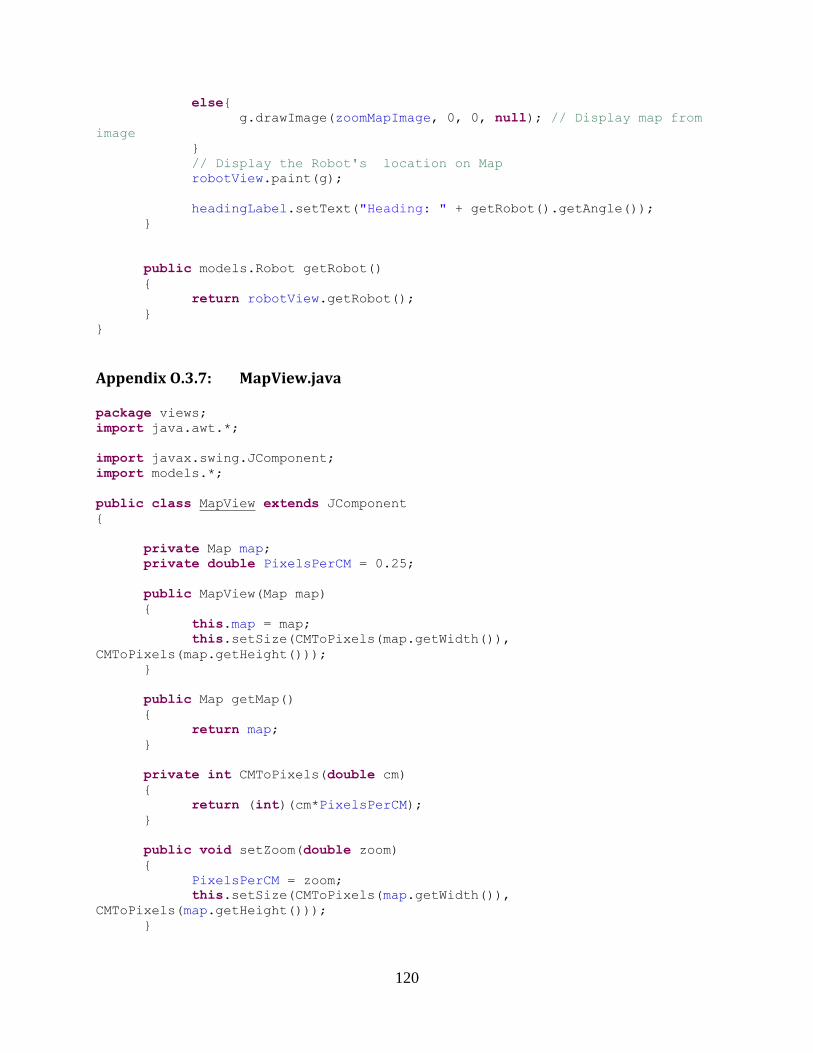
120
else{
g.drawImage(zoomMapImage, 0, 0, null); // Display map from
image
}
// Display the Robot's location on Map
robotView.paint(g);
headingLabel.setText("Heading: " + getRobot().getAngle());
}
public models.Robot getRobot()
{
return robotView.getRobot();
}
}
Appendix O.3.7: MapView.java
package views;
import java.awt.*;
import javax.swing.JComponent;
import models.*;
public class MapView extends JComponent
{
private Map map;
private double PixelsPerCM = 0.25;
public MapView(Map map)
{
this.map = map;
this.setSize(CMToPixels(map.getWidth()),
CMToPixels(map.getHeight()));
}
public Map getMap()
{
return map;
}
private int CMToPixels(double cm)
{
return (int)(cm*PixelsPerCM);
}
public void setZoom(double zoom)
{
PixelsPerCM = zoom;
this.setSize(CMToPixels(map.getWidth()),
CMToPixels(map.getHeight()));
}
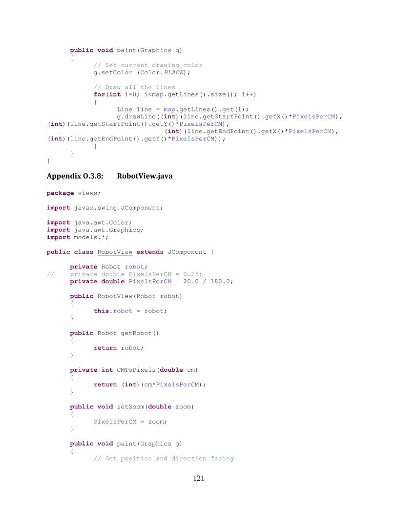
121
public void paint(Graphics g)
{
// Set current drawing color
g.setColor (Color.BLACK);
// Draw all the lines
for(int i=0; i<map.getLines().size(); i++)
{
Line line = map.getLines().get(i);
g.drawLine((int)(line.getStartPoint().getX()*PixelsPerCM),
(int)(line.getStartPoint().getY()*PixelsPerCM),
(int)(line.getEndPoint().getX()*PixelsPerCM),
(int)(line.getEndPoint().getY()*PixelsPerCM));
}
}
}
Appendix O.3.8: RobotView.java
package views;
import javax.swing.JComponent;
import java.awt.Color;
import java.awt.Graphics;
import models.*;
public class RobotView extends JComponent {
private Robot robot;
// private double PixelsPerCM = 0.25;
private double PixelsPerCM = 20.0 / 180.0;
public RobotView(Robot robot)
{
this.robot = robot;
}
public Robot getRobot()
{
return robot;
}
private int CMToPixels(double cm)
{
return (int)(cm*PixelsPerCM);
}
public void setZoom(double zoom)
{
PixelsPerCM = zoom;
}
public void paint(Graphics g)
{
// Get position and direction facing
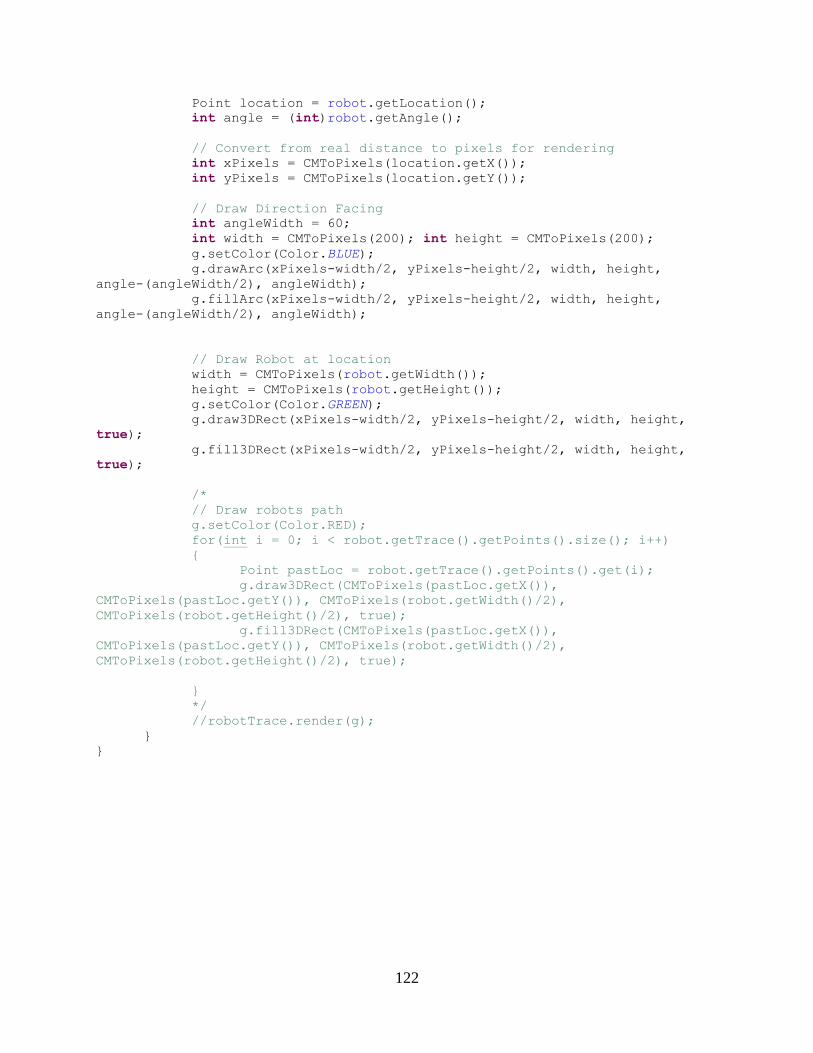
122
Point location = robot.getLocation();
int angle = (int)robot.getAngle();
// Convert from real distance to pixels for rendering
int xPixels = CMToPixels(location.getX());
int yPixels = CMToPixels(location.getY());
// Draw Direction Facing
int angleWidth = 60;
int width = CMToPixels(200); int height = CMToPixels(200);
g.setColor(Color.BLUE);
g.drawArc(xPixels-width/2, yPixels-height/2, width, height,
angle-(angleWidth/2), angleWidth);
g.fillArc(xPixels-width/2, yPixels-height/2, width, height,
angle-(angleWidth/2), angleWidth);
// Draw Robot at location
width = CMToPixels(robot.getWidth());
height = CMToPixels(robot.getHeight());
g.setColor(Color.GREEN);
g.draw3DRect(xPixels-width/2, yPixels-height/2, width, height,
true);
g.fill3DRect(xPixels-width/2, yPixels-height/2, width, height,
true);
/*
// Draw robots path
g.setColor(Color.RED);
for(int i = 0; i < robot.getTrace().getPoints().size(); i++)
{
Point pastLoc = robot.getTrace().getPoints().get(i);
g.draw3DRect(CMToPixels(pastLoc.getX()),
CMToPixels(pastLoc.getY()), CMToPixels(robot.getWidth()/2),
CMToPixels(robot.getHeight()/2), true);
g.fill3DRect(CMToPixels(pastLoc.getX()),
CMToPixels(pastLoc.getY()), CMToPixels(robot.getWidth()/2),
CMToPixels(robot.getHeight()/2), true);
}
*/
//robotTrace.render(g);
}
}
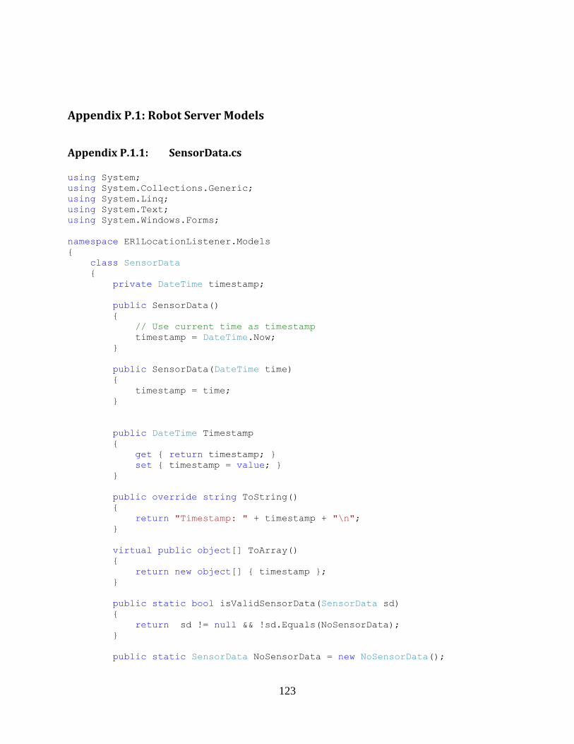
123
Appendix P.1: Robot Server Models
Appendix P.1.1: SensorData.cs
using System;
using System.Collections.Generic;
using System.Linq;
using System.Text;
using System.Windows.Forms;
namespace ER1LocationListener.Models
{
class SensorData
{
private DateTime timestamp;
public SensorData()
{
// Use current time as timestamp
timestamp = DateTime.Now;
}
public SensorData(DateTime time)
{
timestamp = time;
}
public DateTime Timestamp
{
get { return timestamp; }
set { timestamp = value; }
}
public override string ToString()
{
return "Timestamp: " + timestamp + "\n";
}
virtual public object[] ToArray()
{
return new object[] { timestamp };
}
public static bool isValidSensorData(SensorData sd)
{
return sd != null && !sd.Equals(NoSensorData);
}
public static SensorData NoSensorData = new NoSensorData();

124
public static SensorData SensorUpdatingStopped = new
SensorUpdatingStopped();
}
class NoSensorData : SensorData
{
override public string ToString()
{
return "No Sensor Data: " + base.ToString();
}
public override object[] ToArray()
{
return new object[] { "No Sensor Data", base.Timestamp };
}
}
class SensorUpdatingStopped : SensorData
{
override public string ToString()
{
return "Sensor Updating Stopped: " + base.ToString();
}
override public object[] ToArray()
{
return new object[] { "Sensor Updating Stopped", base.Timestamp
};
}
}
}
Appendix P.1.2: EKFState.cs
using System;
using System.Collections.Generic;
using System.Linq;
using System.Text;
namespace ER1LocationListener.Models
{
class EKFState : SensorData
{
private double[] state;
private double[,] covariance;
private string label;
public static int length = 3;
public EKFState() : base()
{
this.state = new double[length];
this.covariance = new double[length, length];
}
public EKFState(double[] state, double[,] covariance) : base()
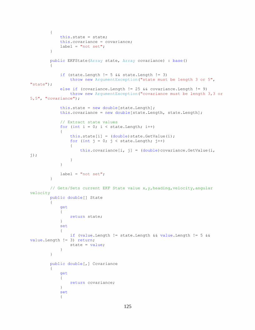
125
{
this.state = state;
this.covariance = covariance;
label = "not set";
}
public EKFState(Array state, Array covariance) : base()
{
if (state.Length != 5 && state.Length != 3)
throw new ArgumentException("state must be length 3 or 5",
"state");
else if (covariance.Length != 25 && covariance.Length != 9)
throw new ArgumentException("covariance must be length 3,3 or
5,5", "covariance");
this.state = new double[state.Length];
this.covariance = new double[state.Length, state.Length];
// Extract state values
for (int i = 0; i < state.Length; i++)
{
this.state[i] = (double)state.GetValue(i);
for (int j = 0; j < state.Length; j++)
{
this.covariance[i, j] = (double)covariance.GetValue(i,
j);
}
}
label = "not set";
}
// Gets/Sets current EKF State value x,y,heading,velocity,angular
velocity
public double[] State
{
get
{
return state;
}
set
{
if (value.Length != state.Length && value.Length != 5 &&
value.Length != 3) return;
state = value;
}
}
public double[,] Covariance
{
get
{
return covariance;
}
set
{
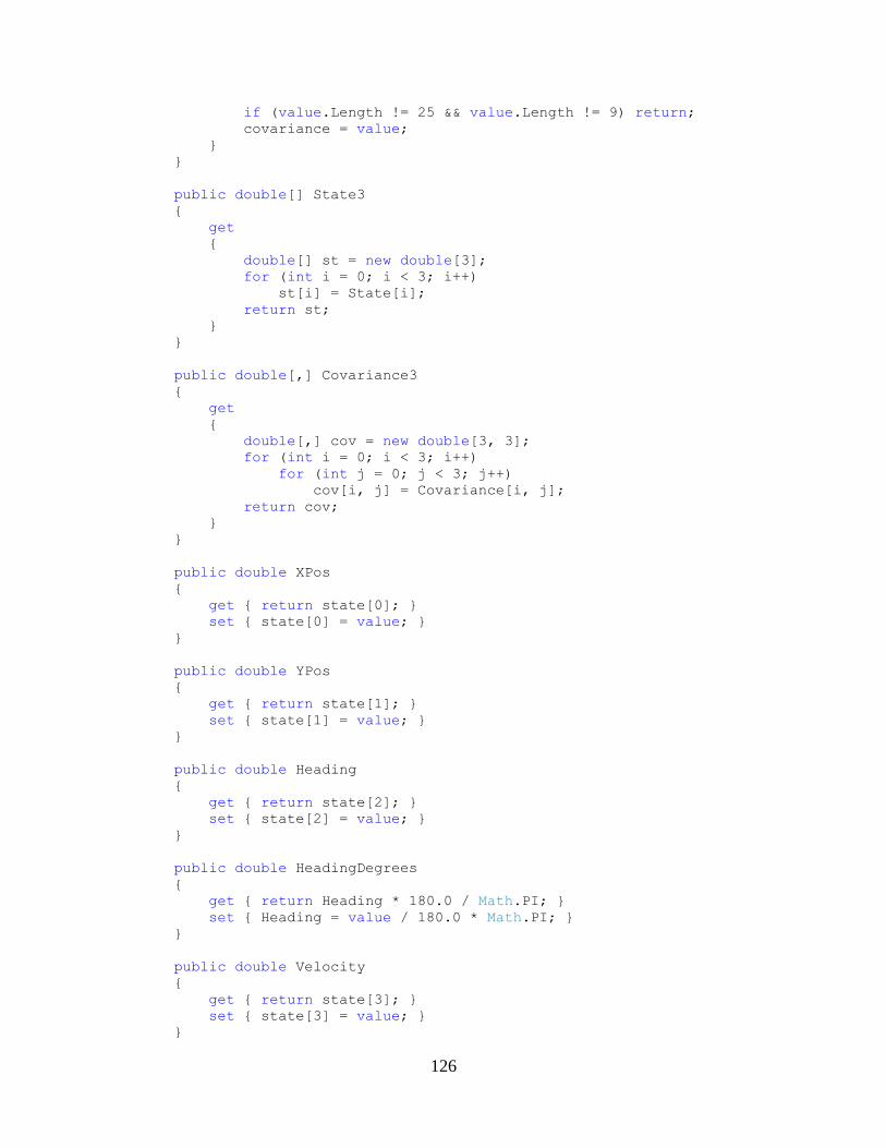
126
if (value.Length != 25 && value.Length != 9) return;
covariance = value;
}
}
public double[] State3
{
get
{
double[] st = new double[3];
for (int i = 0; i < 3; i++)
st[i] = State[i];
return st;
}
}
public double[,] Covariance3
{
get
{
double[,] cov = new double[3, 3];
for (int i = 0; i < 3; i++)
for (int j = 0; j < 3; j++)
cov[i, j] = Covariance[i, j];
return cov;
}
}
public double XPos
{
get { return state[0]; }
set { state[0] = value; }
}
public double YPos
{
get { return state[1]; }
set { state[1] = value; }
}
public double Heading
{
get { return state[2]; }
set { state[2] = value; }
}
public double HeadingDegrees
{
get { return Heading * 180.0 / Math.PI; }
set { Heading = value / 180.0 * Math.PI; }
}
public double Velocity
{
get { return state[3]; }
set { state[3] = value; }
}
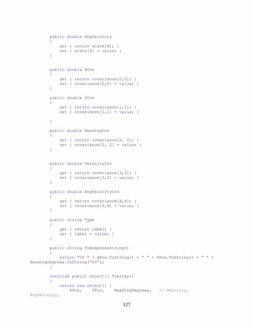
127
public double AngVelocity
{
get { return state[4]; }
set { state[4] = value; }
}
public double XCov
{
get { return covariance[0,0]; }
set { covariance[0,0] = value; }
}
public double YCov
{
get { return covariance[1,1]; }
set { covariance[1,1] = value; }
}
public double HeadingCov
{
get { return covariance[2, 2]; }
set { covariance[2, 2] = value; }
}
public double VelocityCov
{
get { return covariance[3,3]; }
set { covariance[3,3] = value; }
}
public double AngVelocityCov
{
get { return covariance[4,4]; }
set { covariance[4,4] = value; }
}
public string Type
{
get { return label; }
set { label = value; }
}
public string ToResponseString()
{
return "OK " + XPos.ToString() + " " + YPos.ToString() + " " +
HeadingDegrees.ToString("N0");
}
override public object[] ToArray()
{
return new object[] {
XPos, YPos, HeadingDegrees, // Velocity,
AngVelocity,
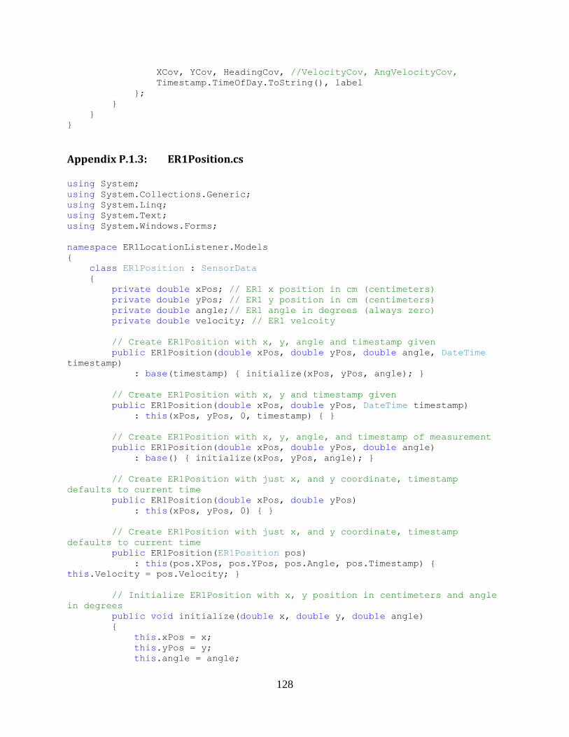
128
XCov, YCov, HeadingCov, //VelocityCov, AngVelocityCov,
Timestamp.TimeOfDay.ToString(), label
};
}
}
}
Appendix P.1.3: ER1Position.cs
using System;
using System.Collections.Generic;
using System.Linq;
using System.Text;
using System.Windows.Forms;
namespace ER1LocationListener.Models
{
class ER1Position : SensorData
{
private double xPos; // ER1 x position in cm (centimeters)
private double yPos; // ER1 y position in cm (centimeters)
private double angle;// ER1 angle in degrees (always zero)
private double velocity; // ER1 velcoity
// Create ER1Position with x, y, angle and timestamp given
public ER1Position(double xPos, double yPos, double angle, DateTime
timestamp)
: base(timestamp) { initialize(xPos, yPos, angle); }
// Create ER1Position with x, y and timestamp given
public ER1Position(double xPos, double yPos, DateTime timestamp)
: this(xPos, yPos, 0, timestamp) { }
// Create ER1Position with x, y, angle, and timestamp of measurement
public ER1Position(double xPos, double yPos, double angle)
: base() { initialize(xPos, yPos, angle); }
// Create ER1Position with just x, and y coordinate, timestamp
defaults to current time
public ER1Position(double xPos, double yPos)
: this(xPos, yPos, 0) { }
// Create ER1Position with just x, and y coordinate, timestamp
defaults to current time
public ER1Position(ER1Position pos)
: this(pos.XPos, pos.YPos, pos.Angle, pos.Timestamp) {
this.Velocity = pos.Velocity; }
// Initialize ER1Position with x, y position in centimeters and angle
in degrees
public void initialize(double x, double y, double angle)
{
this.xPos = x;
this.yPos = y;
this.angle = angle;
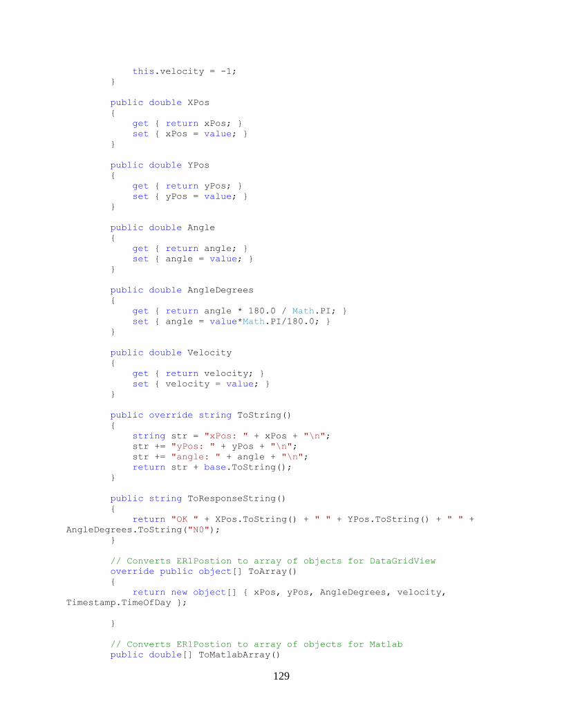
129
this.velocity = -1;
}
public double XPos
{
get { return xPos; }
set { xPos = value; }
}
public double YPos
{
get { return yPos; }
set { yPos = value; }
}
public double Angle
{
get { return angle; }
set { angle = value; }
}
public double AngleDegrees
{
get { return angle * 180.0 / Math.PI; }
set { angle = value*Math.PI/180.0; }
}
public double Velocity
{
get { return velocity; }
set { velocity = value; }
}
public override string ToString()
{
string str = "xPos: " + xPos + "\n";
str += "yPos: " + yPos + "\n";
str += "angle: " + angle + "\n";
return str + base.ToString();
}
public string ToResponseString()
{
return "OK " + XPos.ToString() + " " + YPos.ToString() + " " +
AngleDegrees.ToString("N0");
}
// Converts ER1Postion to array of objects for DataGridView
override public object[] ToArray()
{
return new object[] { xPos, yPos, AngleDegrees, velocity,
Timestamp.TimeOfDay };
}
// Converts ER1Postion to array of objects for Matlab
public double[] ToMatlabArray()
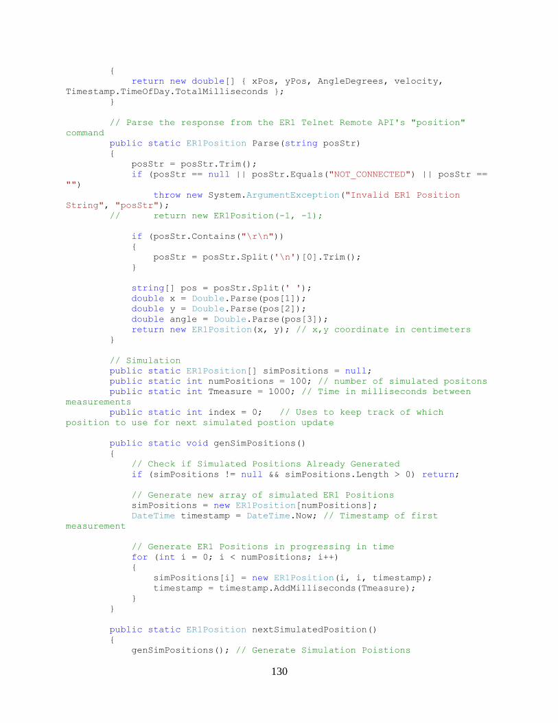
130
{
return new double[] { xPos, yPos, AngleDegrees, velocity,
Timestamp.TimeOfDay.TotalMilliseconds };
}
// Parse the response from the ER1 Telnet Remote API's "position"
command
public static ER1Position Parse(string posStr)
{
posStr = posStr.Trim();
if (posStr == null || posStr.Equals("NOT_CONNECTED") || posStr ==
"")
throw new System.ArgumentException("Invalid ER1 Position
String", "posStr");
// return new ER1Position(-1, -1);
if (posStr.Contains("\r\n"))
{
posStr = posStr.Split('\n')[0].Trim();
}
string[] pos = posStr.Split(' ');
double x = Double.Parse(pos[1]);
double y = Double.Parse(pos[2]);
double angle = Double.Parse(pos[3]);
return new ER1Position(x, y); // x,y coordinate in centimeters
}
// Simulation
public static ER1Position[] simPositions = null;
public static int numPositions = 100; // number of simulated positons
public static int Tmeasure = 1000; // Time in milliseconds between
measurements
public static int index = 0; // Uses to keep track of which
position to use for next simulated postion update
public static void genSimPositions()
{
// Check if Simulated Positions Already Generated
if (simPositions != null && simPositions.Length > 0) return;
// Generate new array of simulated ER1 Positions
simPositions = new ER1Position[numPositions];
DateTime timestamp = DateTime.Now; // Timestamp of first
measurement
// Generate ER1 Positions in progressing in time
for (int i = 0; i < numPositions; i++)
{
simPositions[i] = new ER1Position(i, i, timestamp);
timestamp = timestamp.AddMilliseconds(Tmeasure);
}
}
public static ER1Position nextSimulatedPosition()
{
genSimPositions(); // Generate Simulation Poistions
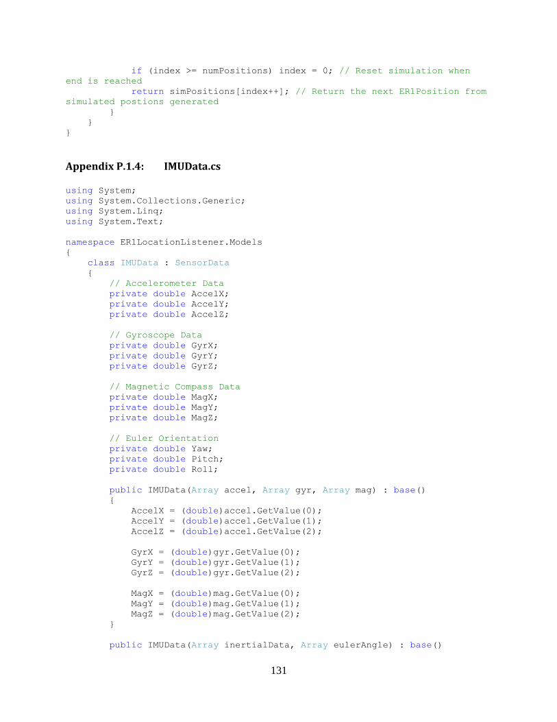
131
if (index >= numPositions) index = 0; // Reset simulation when
end is reached
return simPositions[index++]; // Return the next ER1Position from
simulated postions generated
}
}
}
Appendix P.1.4: IMUData.cs
using System;
using System.Collections.Generic;
using System.Linq;
using System.Text;
namespace ER1LocationListener.Models
{
class IMUData : SensorData
{
// Accelerometer Data
private double AccelX;
private double AccelY;
private double AccelZ;
// Gyroscope Data
private double GyrX;
private double GyrY;
private double GyrZ;
// Magnetic Compass Data
private double MagX;
private double MagY;
private double MagZ;
// Euler Orientation
private double Yaw;
private double Pitch;
private double Roll;
public IMUData(Array accel, Array gyr, Array mag) : base()
{
AccelX = (double)accel.GetValue(0);
AccelY = (double)accel.GetValue(1);
AccelZ = (double)accel.GetValue(2);
GyrX = (double)gyr.GetValue(0);
GyrY = (double)gyr.GetValue(1);
GyrZ = (double)gyr.GetValue(2);
MagX = (double)mag.GetValue(0);
MagY = (double)mag.GetValue(1);
MagZ = (double)mag.GetValue(2);
}
public IMUData(Array inertialData, Array eulerAngle) : base()
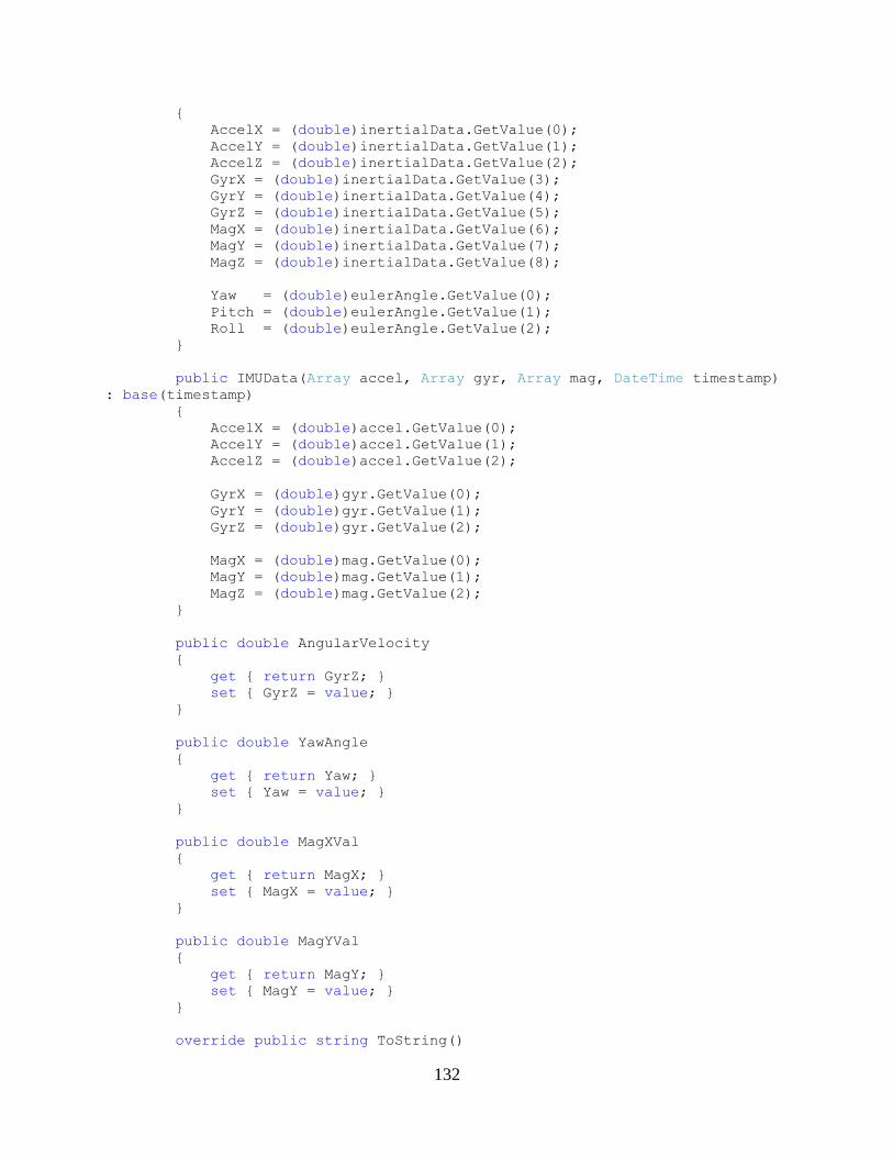
132
{
AccelX = (double)inertialData.GetValue(0);
AccelY = (double)inertialData.GetValue(1);
AccelZ = (double)inertialData.GetValue(2);
GyrX = (double)inertialData.GetValue(3);
GyrY = (double)inertialData.GetValue(4);
GyrZ = (double)inertialData.GetValue(5);
MagX = (double)inertialData.GetValue(6);
MagY = (double)inertialData.GetValue(7);
MagZ = (double)inertialData.GetValue(8);
Yaw = (double)eulerAngle.GetValue(0);
Pitch = (double)eulerAngle.GetValue(1);
Roll = (double)eulerAngle.GetValue(2);
}
public IMUData(Array accel, Array gyr, Array mag, DateTime timestamp)
: base(timestamp)
{
AccelX = (double)accel.GetValue(0);
AccelY = (double)accel.GetValue(1);
AccelZ = (double)accel.GetValue(2);
GyrX = (double)gyr.GetValue(0);
GyrY = (double)gyr.GetValue(1);
GyrZ = (double)gyr.GetValue(2);
MagX = (double)mag.GetValue(0);
MagY = (double)mag.GetValue(1);
MagZ = (double)mag.GetValue(2);
}
public double AngularVelocity
{
get { return GyrZ; }
set { GyrZ = value; }
}
public double YawAngle
{
get { return Yaw; }
set { Yaw = value; }
}
public double MagXVal
{
get { return MagX; }
set { MagX = value; }
}
public double MagYVal
{
get { return MagY; }
set { MagY = value; }
}
override public string ToString()
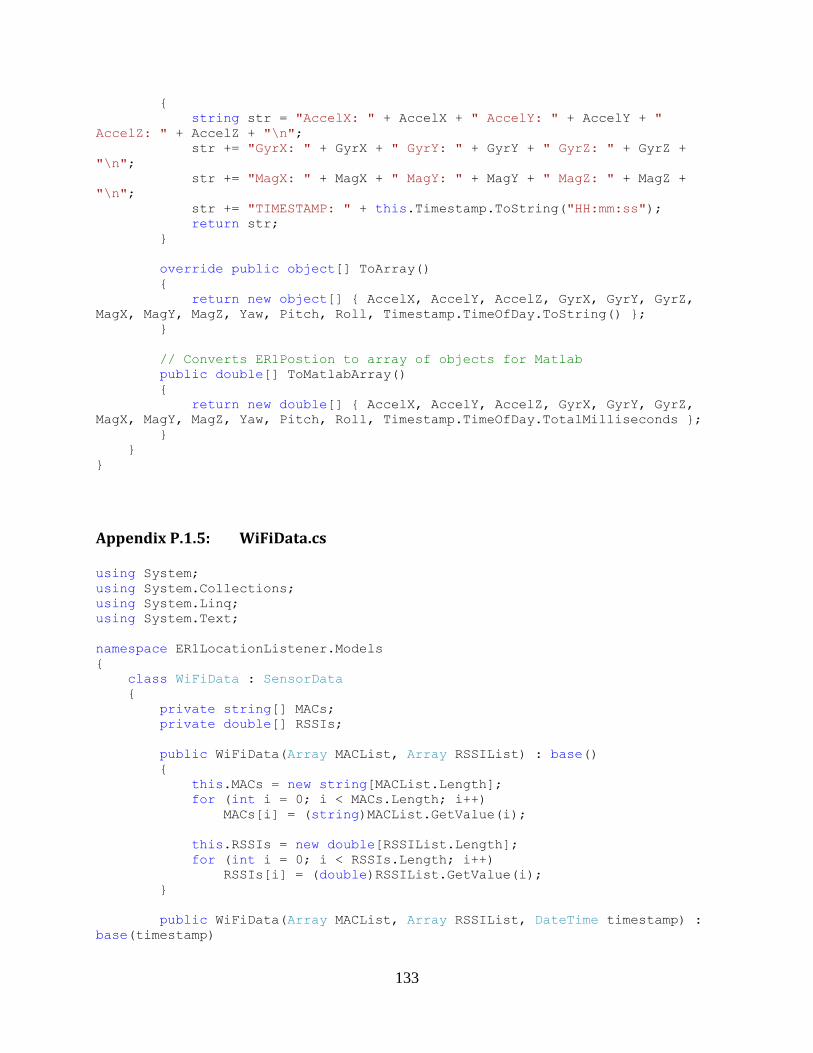
133
{
string str = "AccelX: " + AccelX + " AccelY: " + AccelY + "
AccelZ: " + AccelZ + "\n";
str += "GyrX: " + GyrX + " GyrY: " + GyrY + " GyrZ: " + GyrZ +
"\n";
str += "MagX: " + MagX + " MagY: " + MagY + " MagZ: " + MagZ +
"\n";
str += "TIMESTAMP: " + this.Timestamp.ToString("HH:mm:ss");
return str;
}
override public object[] ToArray()
{
return new object[] { AccelX, AccelY, AccelZ, GyrX, GyrY, GyrZ,
MagX, MagY, MagZ, Yaw, Pitch, Roll, Timestamp.TimeOfDay.ToString() };
}
// Converts ER1Postion to array of objects for Matlab
public double[] ToMatlabArray()
{
return new double[] { AccelX, AccelY, AccelZ, GyrX, GyrY, GyrZ,
MagX, MagY, MagZ, Yaw, Pitch, Roll, Timestamp.TimeOfDay.TotalMilliseconds };
}
}
}
Appendix P.1.5: WiFiData.cs
using System;
using System.Collections;
using System.Linq;
using System.Text;
namespace ER1LocationListener.Models
{
class WiFiData : SensorData
{
private string[] MACs;
private double[] RSSIs;
public WiFiData(Array MACList, Array RSSIList) : base()
{
this.MACs = new string[MACList.Length];
for (int i = 0; i < MACs.Length; i++)
MACs[i] = (string)MACList.GetValue(i);
this.RSSIs = new double[RSSIList.Length];
for (int i = 0; i < RSSIs.Length; i++)
RSSIs[i] = (double)RSSIList.GetValue(i);
}
public WiFiData(Array MACList, Array RSSIList, DateTime timestamp) :
base(timestamp)
134
{
this.MACs = new string[MACList.Length];
for (int i = 0; i < MACs.Length; i++)
MACs[i] = (string)MACList.GetValue(i);
this.RSSIs = new double[RSSIList.Length];
for (int i = 0; i < RSSIs.Length; i++)
RSSIs[i] = (double)RSSIList.GetValue(i);
}
public static WiFiData Parse(string data)
{
// Create array to store all MAC and RSSI data
Array MACList, RSSIList;
// Split the wifiscan string into rows for parsing MAC + RSSI
data
string[] rows = data.Split('\n');
/*
// Extract the timestamp
int timeStart = rows[0].IndexOf("TIME: ") + 6;
int timeLength = rows[0].IndexOf('\r') - timeStart;
string time = rows[0].Substring(timeStart, timeLength);
*/
MACList = new string[rows.Length-2];
RSSIList = new double[rows.Length-2];
for (int i = 1; i < rows.Length-1; i++)
{
if (!rows[i].StartsWith("MAC")){
Console.WriteLine("WiFiData.Parse: Invalid wifidata
row");
continue;
}
// Extract MAC + RSSI from row and save into array
string MAC = rows[i].Substring(rows[i].IndexOf("MAC: \t")+6,
17);
string RSSI = rows[i].Substring(rows[i].IndexOf("RSSI:")+5,
4);
MACList.SetValue(MAC, i-1);
RSSIList.SetValue(int.Parse(RSSI), i-1);
}
// Return the new wifidata object
return new WiFiData(MACList, RSSIList);
}
static public WiFiData Parse2(string data)
{
string[] rows = data.Split('\n');
string[] MACList = new string[rows.Length-1];
double[] RSSIList = new double[rows.Length-1];
for (int i = 0; i < rows.Length-1; i++)
{
MACList[i] = rows[i].Split('\t')[0];
RSSIList[i] = double.Parse(rows[i].Split('\t')[1]);
135
}
return new WiFiData(MACList, RSSIList);
}
public string[] MACArray
{
get { return MACs; }
}
public double[] RSSIArray
{
get { return RSSIs; }
}
public object[] this[int index]
{
get { return new object[] { MACs[index], RSSIs[index] }; }
}
public int Length
{
get { return MACs.Length; }
}
public object this[int i, int j]
{
get { return (j == 0) ? (object)MACs[i] : (object)RSSIs[i]; }
set {
if(j == 0) MACs[i] = (string)value;
else RSSIs[i] = (double)value;
}
}
public override string ToString()
{
string str = "Time Recorded: " +
this.Timestamp.TimeOfDay.ToString() + Environment.NewLine;
for (int i = 0; i < this.Length; i++)
{
str += "MAC: \t" + this[i, 0] + "\tRSSI:" + this[i, 1] + "
dBm\n";
}
return str;
}
override public object[] ToArray()
{
object[] array = new object[this.Length];
for (int i = 0; i < this.Length; i++)
{
array[i] = MACs[i] + " = " + RSSIs[i];
}
return array;
}
public object[,] ToMatlabArray()
{
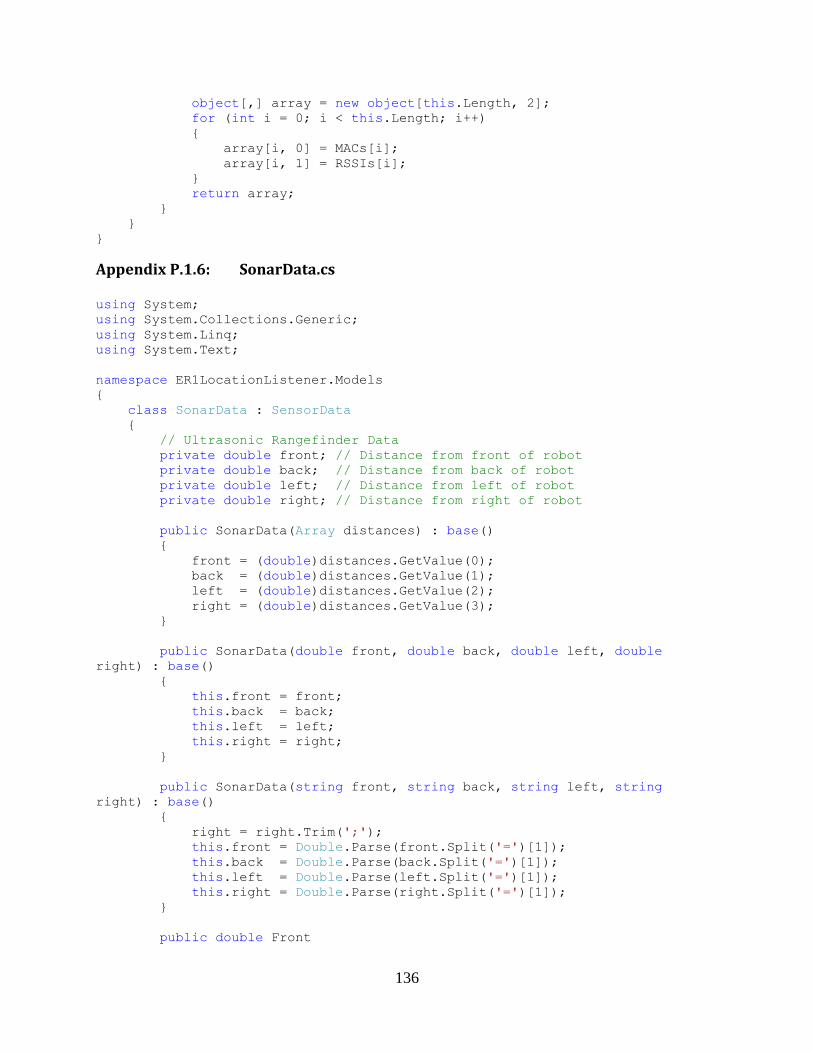
136
object[,] array = new object[this.Length, 2];
for (int i = 0; i < this.Length; i++)
{
array[i, 0] = MACs[i];
array[i, 1] = RSSIs[i];
}
return array;
}
}
}
Appendix P.1.6: SonarData.cs
using System;
using System.Collections.Generic;
using System.Linq;
using System.Text;
namespace ER1LocationListener.Models
{
class SonarData : SensorData
{
// Ultrasonic Rangefinder Data
private double front; // Distance from front of robot
private double back; // Distance from back of robot
private double left; // Distance from left of robot
private double right; // Distance from right of robot
public SonarData(Array distances) : base()
{
front = (double)distances.GetValue(0);
back = (double)distances.GetValue(1);
left = (double)distances.GetValue(2);
right = (double)distances.GetValue(3);
}
public SonarData(double front, double back, double left, double
right) : base()
{
this.front = front;
this.back = back;
this.left = left;
this.right = right;
}
public SonarData(string front, string back, string left, string
right) : base()
{
right = right.Trim(';');
this.front = Double.Parse(front.Split('=')[1]);
this.back = Double.Parse(back.Split('=')[1]);
this.left = Double.Parse(left.Split('=')[1]);
this.right = Double.Parse(right.Split('=')[1]);
}
public double Front
137
{
get { return front; }
set { front = value; }
}
public double Back
{
get { return back; }
set { back = value; }
}
public double Left
{
get { return left; }
set { left = value; }
}
public double Right
{
get { return right; }
set { right = value; }
}
// Converts SonarData to array of objects for Matlab
public double[] ToMatlabArray()
{
return new double[] { Front, Back, Left, Right,
Timestamp.TimeOfDay.TotalMilliseconds };
}
override public string ToString()
{
string str = "Front: " + Front + " Back: " + Back + " Left: " +
Left + " Right: " + Right + "\n";
str += "TIMESTAMP: " + this.Timestamp.ToString("HH:mm:ss");
return str;
}
override public object[] ToArray()
{
return new object[] { Front, Back, Left, Right,
Timestamp.TimeOfDay.ToString() };
}
public static SensorData Parse(string data)
{
string front = "", back = "", left = "", right = "";
string[] parts = data.Split(';');
if (parts.Length != 4 || !data.Contains("front") ||
!data.Contains("back") || !data.Contains("left") || !data.Contains("right"))
{
Console.WriteLine("SonarData: Error parsing sonar data: " +
data);
return SensorData.NoSensorData;
}

138
return new SonarData(parts[0].Trim(), parts[1].Trim(),
parts[2].Trim(), parts[3].Trim());
}
}
}
Appendix P.2: Robot Server Controllers
Appendix P.2.1: SensorController.cs
using System;
using System.Collections;
using System.Linq;
using System.Text;
using System.Timers;
using ER1LocationListener.Models;
namespace ER1LocationListener
{
abstract class SensorController
{
public delegate void SensorUpdateReceievedDelegate(SensorData data);
//private static string[] validRequests = {}; // list of requests
that this Sensor Controller handles
private int interval; // Polling interval for sensor in
milliseconds
protected ArrayList data; // Array of received values
protected bool updating; // Will poll sensor at interval when
updating is true
protected Timer timer; // Timer used for executing doUpdate ever
interval
protected SensorUpdateReceievedDelegate didUpdate;
public SensorUpdateReceievedDelegate SensorUpdateReceived
{
get { return didUpdate; }
set { didUpdate = value; }
}
public SensorController()
{
this.interval = 1000; // set the timer interval to 1
second
updating = false; // initialize controller to disabled
timer = new Timer(interval); // create timer with specified
interval
timer.Elapsed += doUpdate; // Handle time interval elapsed
event with doUpdate
data = new ArrayList(); // Create array to stored past
SensorData
}
139
public SensorController(int interval)
{
this.interval = interval; // set the timer interval
updating = false; // initialize controller to disabled
timer = new Timer(interval); // create timer with specified
interval
timer.Elapsed += doUpdate; // Handle time interval elapsed
event with doUpdate
data = new ArrayList(); // Create array to stored past
SensorData
}
// This function gets called at the specified time interval and is
// repsonsible for reading the current data from the sensor
abstract public void doUpdate(object sender, ElapsedEventArgs e);
// Function to be called every time a new value is received
// public delegate void SensorDataReceievedDelegate(SensorData data);
// starts the polling of sensor data from the sensing hardware
virtual public void startUpdating()
{
timer.Start(); // Start the timer which triggers doUpdate
every time interval
updating = true; // sensor data updating enabled
}
// stops the sensor controller from polling hardware
virtual public void stopUpdating()
{
timer.Stop(); // Start the timer which triggers doUpdate
every time interval
updating = false; // sensor data updating disabled
}
// Returns whether the sensor is polling or not active
public bool isUpdating() { return updating; }
//
// Summary:
// Removes all elements from the ReceivedData
public void Clear()
{
if (data == null) data = new ArrayList(); // If ArrayList
undefined, instantiate it
data.Clear(); // Empty ArrayList of Sensor Data
}
// The rate at which new values are read from sensor
public int TimeInterval
{
get { return interval; }
set { interval = value; }
}
// Array of all received Sensor Data
140
public ArrayList ReceivedData
{
get { return data; }
set { data = value; }
}
// Get the most recently received value from data
public SensorData getCurrentData()
{
// Handle no received data
if (data == null || data.Count == 0) return
SensorData.NoSensorData;
// Return the last Sensor Data in array
return (SensorData)data[data.Count - 1];
}
// The most recent received Sensor Data
public SensorData CurrentData
{
get { return getCurrentData(); } // Get the last received Sensor
Data
set { data.Add(value); } // Add the latest received
Sensor Data to the ReceievedData array
}
//public abstract bool handlesRequest(string request);
/*
public static bool handlesRequest(string request)
{
for (int i = 0; i < validRequests.Length; i++)
{
if (request.StartsWith(validRequests[i]))
return true;
}
return false;
}*/
public double getTimeDiff(SensorData current, SensorData last)
{
double dT = 0;
if (last == null)
{
int i = data.IndexOf(current);
if (i > 0)
last = (IMUData)data[i - 1];
}
if (last != null && !last.Equals(SensorData.NoSensorData))
{
dT =
current.Timestamp.TimeOfDay.Subtract(last.Timestamp.TimeOfDay).Milliseconds;
dT /= 1000.0;
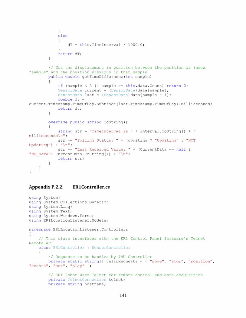
141
}
else
{
dT = this.TimeInterval / 1000.0;
}
return dT;
}
// Get the displacement in position between the position at index
"sample" and the position previous to that sample
public double getTimeDifference(int sample)
{
if (sample < 2 || sample >= this.data.Count) return 0;
SensorData current = (SensorData)data[sample];
SensorData last = (SensorData)data[sample - 1];
double dt =
current.Timestamp.TimeOfDay.Subtract(last.Timestamp.TimeOfDay).Milliseconds;
return dt;
}
override public string ToString()
{
string str = "TimeInterval is " + interval.ToString() + "
milliseconds\n";
str += "Polling Status: " + (updating ? "Updating" : "NOT
Updating") + "\n";
str += "Last Received Value: " + (CurrentData == null ?
"NO_DATA": CurrentData.ToString()) + "\n";
return str;
}
}
}
Appendix P.2.2: ER1Controller.cs
using System;
using System.Collections.Generic;
using System.Linq;
using System.Text;
using System.Windows.Forms;
using ER1LocationListener.Models;
namespace ER1LocationListener.Controllers
{
// This class interfaces with the ER1 Control Panel Software's Telnet
Remote API
class ER1Controller : SensorController
{
// Requests to be handles by IMU Controller
private static string[] validRequests = { "move", "stop", "position",
"events", "set", "play" };
// ER1 Robot uses Telnet for remote control and data acquisition
private TelnetConnection telnet;
private string hostname;
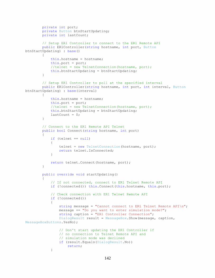
142
private int port;
private Button btnStartUpdating;
private int lastCount;
// Setup ER1 Controller to connect to the ER1 Remote API
public ER1Controller(string hostname, int port, Button
btnStartUpdating) : base()
{
this.hostname = hostname;
this.port = port;
//telnet = new TelnetConnection(hostname, port);
this.btnStartUpdating = btnStartUpdating;
}
// Setup ER1 Controller to poll at the specified interval
public ER1Controller(string hostname, int port, int interval, Button
btnStartUpdating) : base(interval)
{
this.hostname = hostname;
this.port = port;
//telnet = new TelnetConnection(hostname, port);
this.btnStartUpdating = btnStartUpdating;
lastCount = 0;
}
// Connect to the ER1 Remote API Telnet
public bool Connect(string hostname, int port)
{
if (telnet == null)
{
telnet = new TelnetConnection(hostname, port);
return telnet.IsConnected;
}
return telnet.Connect(hostname, port);
}
public override void startUpdating()
{
// If not connected, connect to ER1 Telnet Remote API
if (!connected()) this.Connect(this.hostname, this.port);
// Check connection with ER1 Telnet Remote API
if (!connected())
{
string message = "Cannot connect to ER1 Telnet Remote API\n";
message += "Do you want to enter simulation mode?";
string caption = "ER1 Controller Connection";
DialogResult result = MessageBox.Show(message, caption,
MessageBoxButtons.YesNo);
// Don't start updating the ER1 Controller if
// no connection to Telnet Remote API and
// simulation mode was declined
if (result.Equals(DialogResult.No))
return;
}
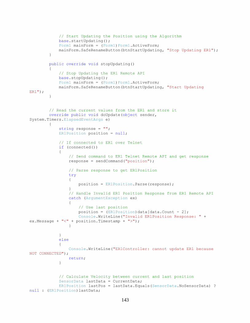
143
// Start Updating the Position using the Algorithm
base.startUpdating();
Form1 mainForm = (Form1)Form1.ActiveForm;
mainForm.SafeRenameButton(btnStartUpdating, "Stop Updating ER1");
}
public override void stopUpdating()
{
// Stop Updating the ER1 Remote API
base.stopUpdating();
Form1 mainForm = (Form1)Form1.ActiveForm;
mainForm.SafeRenameButton(btnStartUpdating, "Start Updating
ER1");
}
// Read the current values from the ER1 and store it
override public void doUpdate(object sender,
System.Timers.ElapsedEventArgs e)
{
string response = "";
ER1Position position = null;
// If connected to ER1 over Telnet
if (connected())
{
// Send command to ER1 Telnet Remote API and get response
response = sendCommand("position");
// Parse response to get ER1Position
try
{
position = ER1Position.Parse(response);
}
// Handle Invalid ER1 Position Response from ER1 Remote API
catch (ArgumentException ex)
{
// Use last position
position = (ER1Position)data[data.Count - 2];
Console.WriteLine("Invalid ER1Position Response: " +
ex.Message + "<" + position.Timestamp + ">");
}
}
else
{
Console.WriteLine("ER1Controller: cannot update ER1 because
NOT CONNECTED");
return;
}
// Calculate Velocity between current and last position
SensorData lastData = CurrentData;
ER1Position lastPos = lastData.Equals(SensorData.NoSensorData) ?
null : (ER1Position)lastData;
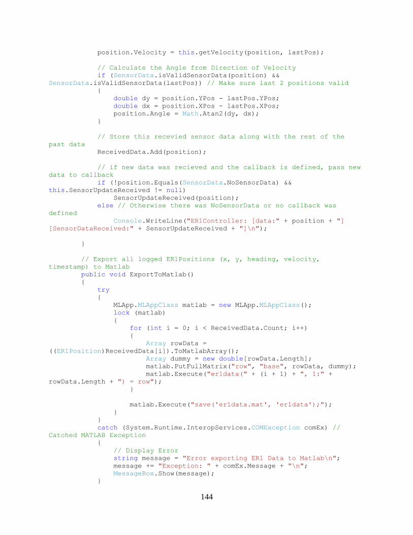
144
position.Velocity = this.getVelocity(position, lastPos);
// Calculate the Angle from Direction of Velocity
if (SensorData.isValidSensorData(position) &&
SensorData.isValidSensorData(lastPos)) // Make sure last 2 positions valid
{
double dy = position.YPos - lastPos.YPos;
double dx = position.XPos - lastPos.XPos;
position.Angle = Math.Atan2(dy, dx);
}
// Store this recevied sensor data along with the rest of the
past data
ReceivedData.Add(position);
// if new data was recieved and the callback is defined, pass new
data to callback
if (!position.Equals(SensorData.NoSensorData) &&
this.SensorUpdateReceived != null)
SensorUpdateReceived(position);
else // Otherwise there was NoSensorData or no callback was
defined
Console.WriteLine("ER1Controller: [data:" + position + "]
[SensorDataReceived:" + SensorUpdateReceived + "]\n");
}
// Export all logged ER1Positions (x, y, heading, velocity,
timestamp) to Matlab
public void ExportToMatlab()
{
try
{
MLApp.MLAppClass matlab = new MLApp.MLAppClass();
lock (matlab)
{
for (int i = 0; i < ReceivedData.Count; i++)
{
Array rowData =
((ER1Position)ReceivedData[i]).ToMatlabArray();
Array dummy = new double[rowData.Length];
matlab.PutFullMatrix("row", "base", rowData, dummy);
matlab.Execute("er1data(" + (i + 1) + ", 1:" +
rowData.Length + ") = row");
}
matlab.Execute("save('er1data.mat', 'er1data');");
}
}
catch (System.Runtime.InteropServices.COMException comEx) //
Catched MATLAB Exception
{
// Display Error
string message = "Error exporting ER1 Data to Matlab\n";
message += "Exception: " + comEx.Message + "\n";
MessageBox.Show(message);
}
145
}
// Sends a command to the ER1 Control Panel's Telnet Remote API and
// Returns its resposne
public string sendCommand(string command)
{
// Make sure we are connected to the ER1 Telnet Remote API
if (!connected()) return "NOT_CONNECTED";
// Send the command through telnet to the ER1 Remote API
telnet.WriteLine(command);
// Read the response of the command from telnet
string response = telnet.Read();
// Return the response
return response;
}
// Returns Telnet Connection status
public bool connected() { return telnet != null &&
telnet.IsConnected; }
// IP Address of the Laptop running the ER1 Control Panel Remote API
(Telnet mode)
public string Hostname
{
get { return hostname; }
set { hostname = value; }
}
// Port of the Laptop running the ER1 Control Panel Remote API
(Telnet mode)
public int Port
{
get { return port; }
set { port = value; }
}
public double getTotalDisplacement()
{
int end = this.data.Count;
int start = lastCount;
double displacement = 0;
double dt_total = 0;
int length = end - start;
if (length < 1)
{
Console.WriteLine("ER1: no ER1 values over " +
this.TimeInterval + "ms to calculate displacement");
return 0;
}
for (int i = start; i < end; i++)
146
{
displacement += getDisplacement(i);
dt_total += getTimeDifference(i);
}
Console.WriteLine("ER1: Displacement in position " + displacement
+ " cm using " + length + "(" + start + ":" + (end - 1) + ") EKF samples over
" + dt_total + " ms");
// Set the index of the last ER1 value used in Displacement
lastCount = end;
return displacement;
}
public double getCurrentDisplacement()
{
return getDisplacement(this.data.Count-1);
}
// Get the displacement in position between the position at index
"sample" and the position previous to that sample
public double getDisplacement(int sample)
{
if (sample < 2 || sample >= this.data.Count) return 0;
ER1Position current = (ER1Position)data[sample];
ER1Position last = (ER1Position)data[sample - 1];
double dx = current.XPos - last.XPos;
double dy = current.YPos - last.YPos;
return Math.Sqrt(dx*dx + dy*dy);
}
public double getVelocity(ER1Position currPos, ER1Position lastPos)
{
// Need at least two position readings to calculate velocity
if (currPos == null || lastPos == null) return 0;
// Calculate the distance and time span between positions
TimeSpan dt =
currPos.Timestamp.TimeOfDay.Subtract(lastPos.Timestamp.TimeOfDay);
double dx = currPos.XPos - lastPos.XPos;
double dy = currPos.YPos - lastPos.YPos;
if (dt.Milliseconds < 1) return lastPos.Velocity;
// Calculate velocity components and vector
double Vx = dx / dt.TotalSeconds;
double Vy = dy / dt.TotalSeconds;
double velocity = Math.Sqrt(Vx * Vx + Vy * Vy);
return velocity;
}
public double getXVelocity()
{
// Need at least two position readings to calculate velocity
if (this.data.Count < 2) return 0;
147
// Get the current and last position to calculate velocity
ER1Position currPos = (ER1Position)this.CurrentData;
ER1Position lastPos = (ER1Position)this.data[this.data.Count -
2];
// Calculate the distance and time span between positions
TimeSpan dt =
currPos.Timestamp.TimeOfDay.Subtract(lastPos.Timestamp.TimeOfDay);
double dx = currPos.XPos - lastPos.XPos;
return dx / dt.TotalSeconds;
}
public double getYVelocity()
{
// Need at least two position readings to calculate velocity
if (this.data.Count < 2) return 0;
// Get the current and last position to calculate velocity
ER1Position currPos = (ER1Position)this.CurrentData;
ER1Position lastPos = (ER1Position)this.data[this.data.Count -
2];
// Calculate the distance and time span between positions
TimeSpan dt =
currPos.Timestamp.TimeOfDay.Subtract(lastPos.Timestamp.TimeOfDay);
double dy = currPos.YPos - lastPos.YPos;
return dy / dt.TotalSeconds;
}
static public bool handlesRequest(string request)
{
for (int i = 0; i < validRequests.Length; i++)
{
if (request.StartsWith(validRequests[i]))
return true;
}
return false;
}
override public string ToString()
{
string str = "ER1Controller Telnet(" + hostname + ":" +
port.ToString() + ")\n";
str += "Telnet Status: " + (connected() ? "Connected!" : "NOT
CONNECTED") + "\n";
str += base.ToString();
return str;
}
public void Clear()
{
base.Clear();
lastCount = 0;
}
}
}

148
Appendix P.2.3: IMUController.cs
using System;
using System.Collections.Generic;
using System.Linq;
using System.Text;
using System.Windows.Forms;
using ER1LocationListener.Models;
using egrath.communication.XSens;
using System.Threading;
namespace ER1LocationListener.Controllers
{
public delegate void DataReceivedDelegate(object sender, ResponseInfo
info);
class IMUController : SensorController
{
private static string[] validRequests = { "getIMUValues" }; //
Requests to be handles by IMU Controller
private MLApp.MLAppClass matlab; // Create MATLAB object to run
scripts
private string scriptName; // Matlab Script to Execute to Read
Values from IMU
private string scriptPath = "c:\\ER1LocationListener\\Matlab\\"; //
Path to Matlab Script Directory
private Button btnStart; // IMU Controller Button for
Starting/Stopping Updating
private static bool simulation = false;
private Connection conn;
private int lastCount; // index of the last IMU data used
private ER1Controller er1Controller;
// Setup IMU Controller to poll at the specified interval
public IMUController(int interval, Button btnStartUpdatingIMU, ref
ER1Controller er1Controller) : base(interval)
{
this.er1Controller = er1Controller;
try
{
btnStart = btnStartUpdatingIMU; // Store the IMU Start
Updating Button
matlab = new MLApp.MLAppClass(); // Instantiate Matlab
Engine
matlab.Execute("cd " + scriptPath); // Change Directory to
Matlab Script Folder
lastCount = 0;
conn = new Connection("COM6");
Connection.DataReceivedEvent ru = new
Connection.DataReceivedEvent(ReceivedUpdate);
conn.DataReceived += ru;
}
catch (System.Runtime.InteropServices.COMException comEx)
{
149
System.Windows.Forms.MessageBox.Show("Message: " +
comEx.Message + "\nStackTrace: " + comEx.StackTrace);
}
}
public void ClearCount()
{
lastCount = 0;
}
public override void startUpdating()
{
try
{
conn.Open();
conn.SetMeasurementMode();
/*
conn.InitMT();
conn.SetConfigMode();
conn.SetOutput(OrientationMode.EulerAngles,
OutputMode.OrientededAndCalibrated);
conn.SetMeasurementMode();
*/
}
catch (Exception ex)
{
MessageBox.Show("Could not connect to IMU: " + ex.Message);
lock (matlab) { matlab.Execute("clear all; close all;"); }
return;
}
base.startUpdating();
Form1 mainForm = (Form1)Form1.ActiveForm;
mainForm.SafeRenameButton(btnStart, "Stop Updating IMU");
return;
}
public override void stopUpdating()
{
conn.Close();
base.stopUpdating();
Form1 mainForm = (Form1)Form1.ActiveForm;
mainForm.SafeRenameButton(btnStart, "Start Updating IMU");
}
public void ReceivedUpdate(object sender, ResponseInfo info)
{
// Extract measured IMU data
Array inertial, eular;
if (info.Type == ResponseInfoType.EulerAnglesAndCalibrated ||
info.Type == ResponseInfoType.Calibrated)
{
inertial = new double[] { info.accX, info.accY, info.accZ,
info.gyrX, info.gyrY, info.gyrZ, info.magX, info.magY, info.magZ };
eular = new double[] { info.Yaw, info.Pitch, info.Roll };
}
else
{
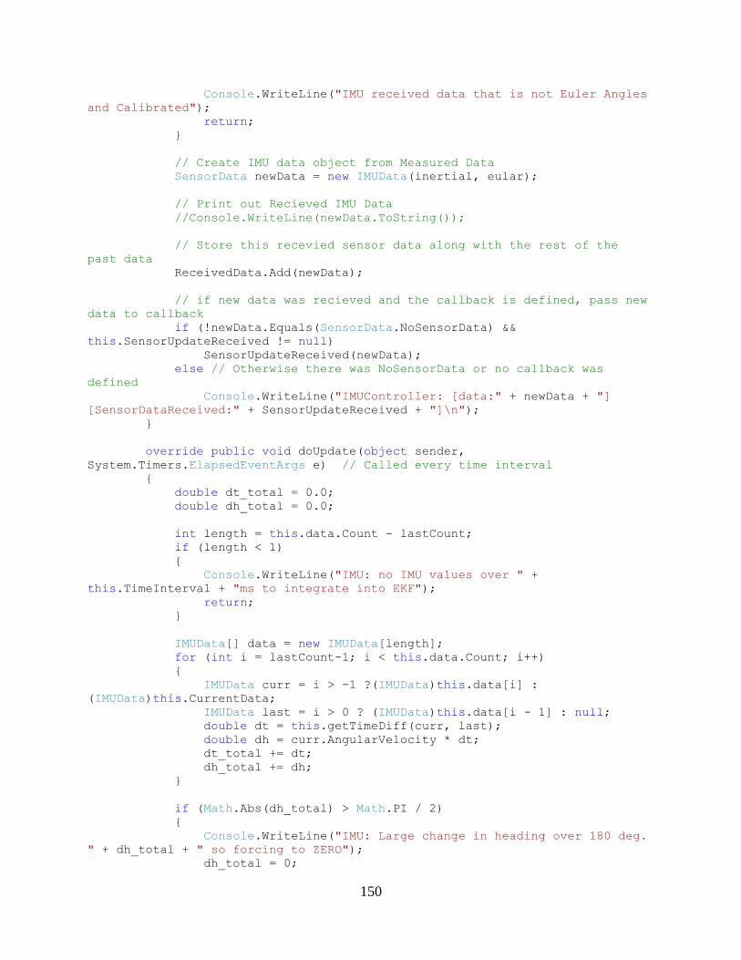
150
Console.WriteLine("IMU received data that is not Euler Angles
and Calibrated");
return;
}
// Create IMU data object from Measured Data
SensorData newData = new IMUData(inertial, eular);
// Print out Recieved IMU Data
//Console.WriteLine(newData.ToString());
// Store this recevied sensor data along with the rest of the
past data
ReceivedData.Add(newData);
// if new data was recieved and the callback is defined, pass new
data to callback
if (!newData.Equals(SensorData.NoSensorData) &&
this.SensorUpdateReceived != null)
SensorUpdateReceived(newData);
else // Otherwise there was NoSensorData or no callback was
defined
Console.WriteLine("IMUController: [data:" + newData + "]
[SensorDataReceived:" + SensorUpdateReceived + "]\n");
}
override public void doUpdate(object sender,
System.Timers.ElapsedEventArgs e) // Called every time interval
{
double dt_total = 0.0;
double dh_total = 0.0;
int length = this.data.Count - lastCount;
if (length < 1)
{
Console.WriteLine("IMU: no IMU values over " +
this.TimeInterval + "ms to integrate into EKF");
return;
}
IMUData[] data = new IMUData[length];
for (int i = lastCount-1; i < this.data.Count; i++)
{
IMUData curr = i > -1 ?(IMUData)this.data[i] :
(IMUData)this.CurrentData;
IMUData last = i > 0 ? (IMUData)this.data[i - 1] : null;
double dt = this.getTimeDiff(curr, last);
double dh = curr.AngularVelocity * dt;
dt_total += dt;
dh_total += dh;
}
if (Math.Abs(dh_total) > Math.PI / 2)
{
Console.WriteLine("IMU: Large change in heading over 180 deg.
" + dh_total + " so forcing to ZERO");
dh_total = 0;
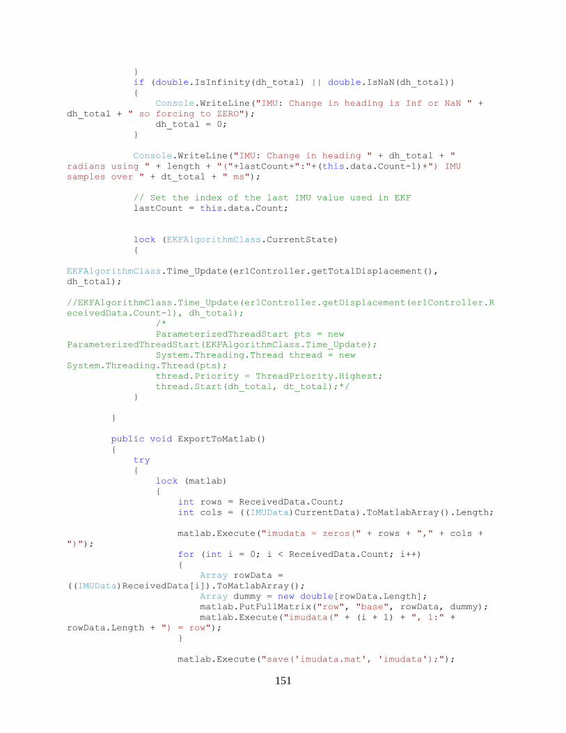
151
}
if (double.IsInfinity(dh_total) || double.IsNaN(dh_total))
{
Console.WriteLine("IMU: Change in heading is Inf or NaN " +
dh_total + " so forcing to ZERO");
dh_total = 0;
}
Console.WriteLine("IMU: Change in heading " + dh_total + "
radians using " + length + "("+lastCount+":"+(this.data.Count-1)+") IMU
samples over " + dt_total + " ms");
// Set the index of the last IMU value used in EKF
lastCount = this.data.Count;
lock (EKFAlgorithmClass.CurrentState)
{
EKFAlgorithmClass.Time_Update(er1Controller.getTotalDisplacement(),
dh_total);
//EKFAlgorithmClass.Time_Update(er1Controller.getDisplacement(er1Controller.R
eceivedData.Count-1), dh_total);
/*
ParameterizedThreadStart pts = new
ParameterizedThreadStart(EKFAlgorithmClass.Time_Update);
System.Threading.Thread thread = new
System.Threading.Thread(pts);
thread.Priority = ThreadPriority.Highest;
thread.Start(dh_total, dt_total);*/
}
}
public void ExportToMatlab()
{
try
{
lock (matlab)
{
int rows = ReceivedData.Count;
int cols = ((IMUData)CurrentData).ToMatlabArray().Length;
matlab.Execute("imudata = zeros(" + rows + "," + cols +
")");
for (int i = 0; i < ReceivedData.Count; i++)
{
Array rowData =
((IMUData)ReceivedData[i]).ToMatlabArray();
Array dummy = new double[rowData.Length];
matlab.PutFullMatrix("row", "base", rowData, dummy);
matlab.Execute("imudata(" + (i + 1) + ", 1:" +
rowData.Length + ") = row");
}
matlab.Execute("save('imudata.mat', 'imudata');");
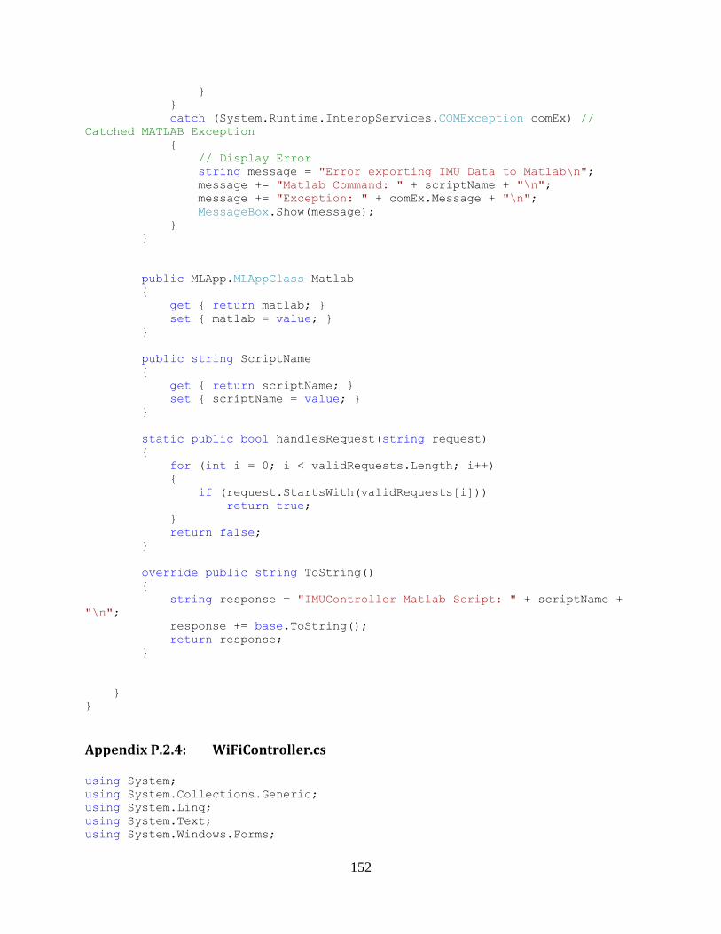
152
}
}
catch (System.Runtime.InteropServices.COMException comEx) //
Catched MATLAB Exception
{
// Display Error
string message = "Error exporting IMU Data to Matlab\n";
message += "Matlab Command: " + scriptName + "\n";
message += "Exception: " + comEx.Message + "\n";
MessageBox.Show(message);
}
}
public MLApp.MLAppClass Matlab
{
get { return matlab; }
set { matlab = value; }
}
public string ScriptName
{
get { return scriptName; }
set { scriptName = value; }
}
static public bool handlesRequest(string request)
{
for (int i = 0; i < validRequests.Length; i++)
{
if (request.StartsWith(validRequests[i]))
return true;
}
return false;
}
override public string ToString()
{
string response = "IMUController Matlab Script: " + scriptName +
"\n";
response += base.ToString();
return response;
}
}
}
Appendix P.2.4: WiFiController.cs
using System;
using System.Collections.Generic;
using System.Linq;
using System.Text;
using System.Windows.Forms;
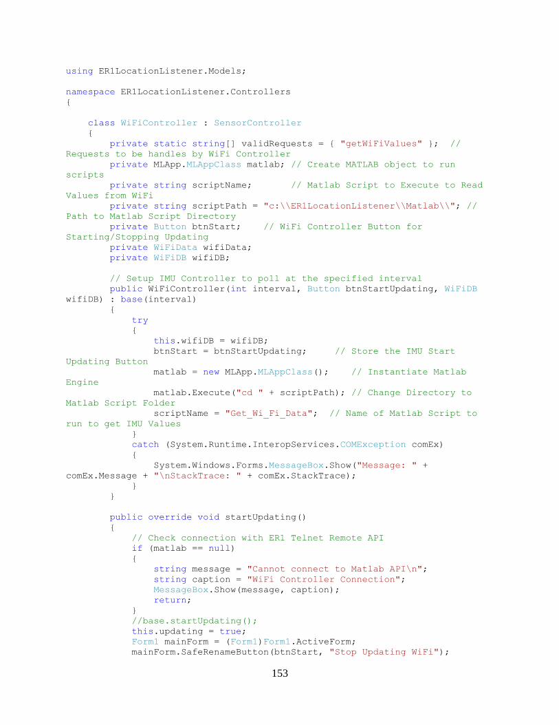
153
using ER1LocationListener.Models;
namespace ER1LocationListener.Controllers
{
class WiFiController : SensorController
{
private static string[] validRequests = { "getWiFiValues" }; //
Requests to be handles by WiFi Controller
private MLApp.MLAppClass matlab; // Create MATLAB object to run
scripts
private string scriptName; // Matlab Script to Execute to Read
Values from WiFi
private string scriptPath = "c:\\ER1LocationListener\\Matlab\\"; //
Path to Matlab Script Directory
private Button btnStart; // WiFi Controller Button for
Starting/Stopping Updating
private WiFiData wifiData;
private WiFiDB wifiDB;
// Setup IMU Controller to poll at the specified interval
public WiFiController(int interval, Button btnStartUpdating, WiFiDB
wifiDB) : base(interval)
{
try
{
this.wifiDB = wifiDB;
btnStart = btnStartUpdating; // Store the IMU Start
Updating Button
matlab = new MLApp.MLAppClass(); // Instantiate Matlab
Engine
matlab.Execute("cd " + scriptPath); // Change Directory to
Matlab Script Folder
scriptName = "Get_Wi_Fi_Data"; // Name of Matlab Script to
run to get IMU Values
}
catch (System.Runtime.InteropServices.COMException comEx)
{
System.Windows.Forms.MessageBox.Show("Message: " +
comEx.Message + "\nStackTrace: " + comEx.StackTrace);
}
}
public override void startUpdating()
{
// Check connection with ER1 Telnet Remote API
if (matlab == null)
{
string message = "Cannot connect to Matlab API\n";
string caption = "WiFi Controller Connection";
MessageBox.Show(message, caption);
return;
}
//base.startUpdating();
this.updating = true;
Form1 mainForm = (Form1)Form1.ActiveForm;
mainForm.SafeRenameButton(btnStart, "Stop Updating WiFi");
154
}
public override void stopUpdating()
{
base.stopUpdating();
Form1 mainForm = (Form1)Form.ActiveForm;
mainForm.SafeRenameButton(btnStart, "Start Updating WiFi");
}
// Read the current values from the WiFi and store it
override public void doUpdate(object sender,
System.Timers.ElapsedEventArgs e ) // Called every time interval
{
// Wait for this Update to Complete before starting next Update
//timer.Stop();
DateTime start = DateTime.Now;
SensorData newData = SensorData.NoSensorData;
try
{
// Get the current wifi access points
Array MACs = CurrentWiFiData.MACArray;
Array RSSIs = CurrentWiFiData.RSSIArray;
Array dummy1 = new string[MACs.Length];
Array dummy2 = new double[RSSIs.Length];
if (MACs.Length < 10) return;
lock (matlab)
{
// Execute the Matlab script to read values
// matlab.Execute("cd " + scriptPath); // Change
Directory to Matlab Script Folder
// Put MAC+RSSI List for WiFi Get Position into MATLAB
workspace
matlab.PutWorkspaceData("MACs", "base", MACs);
matlab.PutFullMatrix("RSSIs", "base", RSSIs, dummy2);
string response = matlab.Execute("position =
Get_WiFi_Position(MACs, RSSIs);");
Console.WriteLine("WiFiController script output: " +
response);
DateTime end = DateTime.Now;
Console.WriteLine("WiFi Update to execute took: " +
(end.TimeOfDay.Subtract(start.TimeOfDay)) + "\n");
// Get the updated values from Matlab
Array position = new double[2];
Array dummy = new double[2]; // dummy variable for
matlabs imaginary
matlab.GetFullMatrix("position", "base", ref position,
ref dummy);
155
// Create WiFi Data object from the Matlab script's
output variables
double xPos = (double)position.GetValue(0);
double yPos = (double)position.GetValue(1);
newData = new ER1Position(xPos, yPos); // SensorData
timestamped automatically with current time
ReceivedData.Add(newData); // Store this recevied
sensor data along with the rest of the past data
}
}
catch (System.Runtime.InteropServices.COMException comEx) //
Catched MATLAB Exception
{
// Stop received updates from IMU since Matlab Exception
occured
stopUpdating();
// Show user the exception and ask whether to continue
receiving updates
string message = "Message: " + comEx.Message + "\n";
message += "Data: " + newData + "\n";
message += "Continue receiving updates from WiFi
Controller?";
string caption = "WiFi Controller Matlab Exception";
DialogResult result = MessageBox.Show(message, caption,
MessageBoxButtons.YesNo);
// Start updates back up if user chooses
if (result.Equals(DialogResult.Yes))
startUpdating();
else
newData = SensorData.SensorUpdatingStopped;
}
// Update complete so allow further sensor updates to be trigger
// (isUpdating()) timer.Start();
// if new data was recieved and the callback is defined, pass new
data to callback
if(!newData.Equals(SensorData.NoSensorData) &&
this.SensorUpdateReceived != null)
SensorUpdateReceived(newData);
else // Otherwise there was NoSensorData or no callback was
defined
Console.WriteLine("WiFiController: [data:"+newData+"]
[SensorDataReceived:"+SensorUpdateReceived+"]\n");
/*
DateTime endtime = DateTime.Now;
Console.WriteLine("WiFi Update to finsih took: " +
(endtime.TimeOfDay.Subtract(start.TimeOfDay)) + "\n");
*/
}

156
public void ExportToMatlab()
{
try
{
lock (matlab)
{
for (int i = 0; i < ReceivedData.Count; i++)
{
Array rowData =
((ER1Position)ReceivedData[i]).ToMatlabArray();
Array dummy = new double[rowData.Length];
matlab.PutFullMatrix("row", "base", rowData, dummy);
matlab.Execute("wifidata(" + (i + 1) + ", 1:" +
rowData.Length + ") = row");
}
matlab.Execute("save('wifidata.mat', 'wifidata');");
}
}
catch (System.Runtime.InteropServices.COMException comEx) //
Catched MATLAB Exception
{
// Display Error
string message = "Error exporting WiFi Data to Matlab\n";
message += "Matlab Command: " + scriptName + "\n";
message += "Exception: " + comEx.Message + "\n";
MessageBox.Show(message);
}
}
public void ReceiveWiFiData(WiFiData wifiData)
{
lock (this)
{
this.wifiData = wifiData;
if (wifiDB.NeedsSample)
{
wifiDB.Add(this.CurrentWiFiData);
}
if (this.isUpdating())
this.doUpdate(null,null);
}
}
public WiFiData CurrentWiFiData
{
get {
lock(wifiData) {
return wifiData;
}
}
set {
lock(wifiData) {
wifiData = value;
}
157
}
}
public MLApp.MLAppClass Matlab
{
get { return matlab; }
set { matlab = value; }
}
public string ScriptName
{
get { return scriptName; }
set { scriptName = value; }
}
static public bool handlesRequest(string request)
{
for (int i = 0; i < validRequests.Length; i++)
{
if (request.StartsWith(validRequests[i]))
return true;
}
return false;
}
override public string ToString()
{
string response = "IMUController Matlab Script: " + scriptName +
"\n";
response += base.ToString();
return response;
}
}
}
Appendix P.2.5: SonarController.cs
using System;
using System.Collections.Generic;
using System.Linq;
using System.Text;
using System.Windows.Forms;
using System.IO.Ports;
using ER1LocationListener.Models;
namespace ER1LocationListener.Controllers
{
class SonarController : SensorController
{
private static string[] validRequests = { "getSonarValues" }; //
Requests to be handles by Sonar Controller
private Button btnStart; // IMU Controller Button for
Starting/Stopping Updating
private SerialPort sonar;

158
// Setup Sonar Controller to poll at the specified interval
public SonarController(int interval, Button btnStartUpdating) :
base(interval)
{
try
{
btnStart = btnStartUpdating; // Store the Start Updating
Button
Init_Sonar_Sensor();
}
catch (Exception ex)
{
System.Windows.Forms.MessageBox.Show("Message: " + ex.Message
+ "\nStackTrace: " + ex.StackTrace);
}
}
public override void startUpdating()
{
Start_Sonar_Sensor();
base.startUpdating();
Form1 mainForm = (Form1)Form1.ActiveForm;
mainForm.SafeRenameButton(btnStart, "Stop Updating Sonar");
}
public override void stopUpdating()
{
Stop_Sonar_Sensor();
base.stopUpdating();
Form1 mainForm = (Form1)Form1.ActiveForm;
mainForm.SafeRenameButton(btnStart, "Start Updating Sonar");
}
private void Init_Sonar_Sensor()
{
string COMPort = "COM12";
int baudrate = 115200;
sonar = new SerialPort(COMPort, baudrate);
}
private void Start_Sonar_Sensor()
{
sonar.Open();
}
private void Stop_Sonar_Sensor()
{
sonar.Close();
}
private string Get_Sonar_Data()
{
try
{
return sonar.ReadLine();
}
159
catch (Exception ex)
{
Console.WriteLine("Sonar Error: " + ex.Message + "\n
StackTrace: " + ex.StackTrace);
return "ERROR";
}
}
// Read the current values from the IMU and store it
override public void doUpdate(object sender,
System.Timers.ElapsedEventArgs e ) // Called every time interval
{
// Run MATLAB Script to Read Ultrasonic Distance Values
SensorData newData = SensorData.NoSensorData;
string response = "NO_RESPONSE";
try
{
lock (this)
{
// Create Ultrasonic Data object from the Sonar's output
variables
string sonarData = Get_Sonar_Data();
Console.WriteLine("Sonar Read: " + sonarData);
newData = SonarData.Parse(sonarData);
Console.WriteLine("Sonar Parsed: " + newData.ToString());
// Store this recevied sensor data along with the rest of
the past data
ReceivedData.Add(newData);
}
}
catch (Exception ex) // Catched MATLAB Exception
{
// Stop received updates from IMU since Matlab Exception
occured
stopUpdating();
string message = "Sonar Controller Ex: " + ex.Message + "\n";
message += "Trace: " + ex.StackTrace + "\n";
MessageBox.Show(message);
newData = SensorData.SensorUpdatingStopped;
Form1 form = (Form1)Form1.ActiveForm;
form.SafeRenameButton(btnStart, "Stop Updating Sonar");
}
// if new data was recieved and the callback is defined, pass new
data to callback
if(!newData.Equals(SensorData.NoSensorData) &&
this.SensorUpdateReceived != null)
SensorUpdateReceived(newData);
else // Otherwise there was NoSensorData or no callback was
defined
Console.WriteLine("IMUController: [data:"+newData+"]
[SensorDataReceived:"+SensorUpdateReceived+"]\n");
}
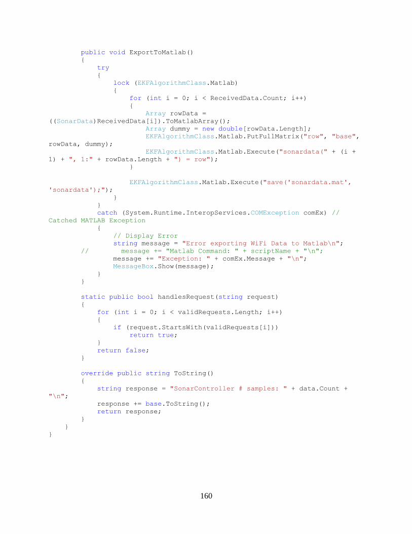
160
public void ExportToMatlab()
{
try
{
lock (EKFAlgorithmClass.Matlab)
{
for (int i = 0; i < ReceivedData.Count; i++)
{
Array rowData =
((SonarData)ReceivedData[i]).ToMatlabArray();
Array dummy = new double[rowData.Length];
EKFAlgorithmClass.Matlab.PutFullMatrix("row", "base",
rowData, dummy);
EKFAlgorithmClass.Matlab.Execute("sonardata(" + (i +
1) + ", 1:" + rowData.Length + ") = row");
}
EKFAlgorithmClass.Matlab.Execute("save('sonardata.mat',
'sonardata');");
}
}
catch (System.Runtime.InteropServices.COMException comEx) //
Catched MATLAB Exception
{
// Display Error
string message = "Error exporting WiFi Data to Matlab\n";
// message += "Matlab Command: " + scriptName + "\n";
message += "Exception: " + comEx.Message + "\n";
MessageBox.Show(message);
}
}
static public bool handlesRequest(string request)
{
for (int i = 0; i < validRequests.Length; i++)
{
if (request.StartsWith(validRequests[i]))
return true;
}
return false;
}
override public string ToString()
{
string response = "SonarController # samples: " + data.Count +
"\n";
response += base.ToString();
return response;
}
}
}
161
Appendix P.2.6: WiFiDB.cs
using System;
using System.Collections;
using System.Collections.Generic;
using System.Linq;
using System.Text;
using ER1LocationListener.Models;
using System.Windows.Forms;
namespace ER1LocationListener.Controllers
{
class WiFiDB
{
public delegate void WiFiSamplesReceievedDelegate(WiFiDB data);
private WiFiSamplesReceievedDelegate gotAllWiFiSamples;
private string name;
private ArrayList samples;
private MLApp.MLAppClass matlab;
private int samplesToRead;
private int samplesRead;
private TextBox txtTotalSamplesRead;
private Form1 mainForm;
public WiFiSamplesReceievedDelegate onAllWiFiSamplesReceived
{
get { return gotAllWiFiSamples; }
set { gotAllWiFiSamples = value; }
}
public WiFiDB(TextBox txtSamplesRead, Form1 form)
{
name = "not_set";
samples = new ArrayList();
try
{
matlab = new MLApp.MLAppClass();
}
catch (Exception ex)
{
Console.WriteLine("Cannot Load Matlab...");
}
samplesToRead = 0;
this.txtTotalSamplesRead = txtSamplesRead;
mainForm = form;
}
public bool NeedsSample
{
get { return SamplesRead < SamplesToRead; }
}
162
public void Add(WiFiData wifiData)
{
samples.Add(wifiData);
samplesRead++;
UpdateTotalSamplesReadTextBox();
if (!NeedsSample && gotAllWiFiSamples != null)
{
gotAllWiFiSamples(this);
}
}
public void Clear()
{
samples.Clear();
samplesRead = 0;
samplesToRead = 0;
UpdateTotalSamplesReadTextBox();
}
private void UpdateTotalSamplesReadTextBox()
{
mainForm.SafeSetText(this.txtTotalSamplesRead,
TotalSamplesRead.ToString());
}
public string Name
{
get { return name; }
set { name = value; }
}
public int TotalSamplesRead
{
get { return samples.Count; }
}
public int SamplesRead
{
get { return samplesRead; }
set { samplesRead = value; }
}
public int SamplesToRead
{
get { return samplesToRead; }
set { samplesToRead = value; }
}
public int findMaxAPs()
{
int maxAPs = 0;
foreach (WiFiData wifiData in samples)
{
if (wifiData.Length > maxAPs) maxAPs = wifiData.Length;
}
163
return maxAPs;
}
public void save(bool asFile)
{
int sampleNum = 1;
matlab.Execute("sampleMACs = cell(" + samples.Count +
","+findMaxAPs()+");");
matlab.Execute("sampleRSSIs = zeros(" + samples.Count +
","+findMaxAPs()+");");
foreach(WiFiData wifiData in samples)
{
matlab.PutWorkspaceData("MACs", "base", wifiData.MACArray);
matlab.PutWorkspaceData("RSSIs", "base", wifiData.RSSIArray);
matlab.Execute("sampleMACs(" + sampleNum + ",1:length(MACs))
= MACs;");
matlab.Execute("sampleRSSIs(" + sampleNum +
",1:length(RSSIs)) = RSSIs;");
sampleNum++;
}
if (asFile)
{
matlab.Execute("save('" + name + "MACs.mat', 'sampleMACs')");
matlab.Execute("save('" + name + "RSSIs.mat',
'sampleRSSIs')");
}
}
}
}
Appendix P.2.7: EKFAlgorithmClass.cs
using System;
using System.Collections.Generic;
using System.Linq;
using System.Text;
using ER1LocationListener.Models;
using System.Collections;
using System.Windows.Forms;
namespace ER1LocationListener.Controllers
{
static class EKFAlgorithmClass
{
private static ArrayList ReceivedData;
private static EKFState currentState;
private static MLApp.MLAppClass matlab; // Create MATLAB object to
run scripts
private static string scriptName = "Time_Update"; // Matlab
Script to Execute to Read Values from IMU
public delegate void SensorUpdateReceievedDelegate(SensorData data);
private static SensorUpdateReceievedDelegate didUpdate;
public static SensorUpdateReceievedDelegate SensorUpdateReceived
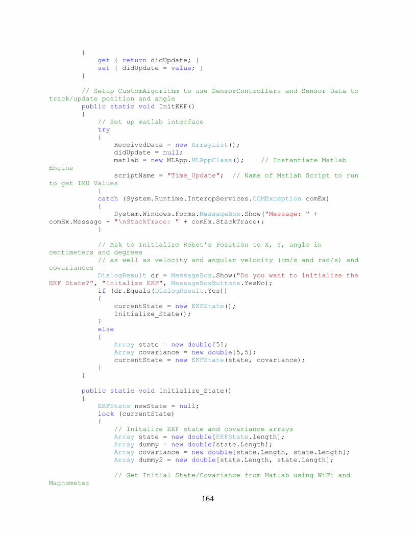
164
{
get { return didUpdate; }
set { didUpdate = value; }
}
// Setup CustomAlgorithm to use SensorControllers and Sensor Data to
track/update position and angle
public static void InitEKF()
{
// Set up matlab interface
try
{
ReceivedData = new ArrayList();
didUpdate = null;
matlab = new MLApp.MLAppClass(); // Instantiate Matlab
Engine
scriptName = "Time_Update"; // Name of Matlab Script to run
to get IMU Values
}
catch (System.Runtime.InteropServices.COMException comEx)
{
System.Windows.Forms.MessageBox.Show("Message: " +
comEx.Message + "\nStackTrace: " + comEx.StackTrace);
}
// Ask to Initialize Robot's Position to X, Y, angle in
centimeters and degrees
// as well as velocity and angular velocity (cm/s and rad/s) and
covariances
DialogResult dr = MessageBox.Show("Do you want to initialize the
EKF State?", "Initalize EKF", MessageBoxButtons.YesNo);
if (dr.Equals(DialogResult.Yes))
{
currentState = new EKFState();
Initialize_State();
}
else
{
Array state = new double[5];
Array covariance = new double[5,5];
currentState = new EKFState(state, covariance);
}
}
public static void Initialize_State()
{
EKFState newState = null;
lock (currentState)
{
// Initalize EKF state and covariance arrays
Array state = new double[EKFState.length];
Array dummy = new double[state.Length];
Array covariance = new double[state.Length, state.Length];
Array dummy2 = new double[state.Length, state.Length];
// Get Initial State/Covariance from Matlab using WiFi and
Magnometer

165
try
{
lock (matlab)
{
string repsonse = matlab.Execute("Initialize_State");
matlab.GetFullMatrix("x", "base", ref state, ref
dummy);
matlab.GetFullMatrix("P", "base", ref covariance, ref
dummy2);
}
}
catch (Exception ex)
{
Console.WriteLine("EKF Init State error: " + ex.Message);
// matlab failed so used hard coded values
state = new double[] { 0, 0, 0};//, 0.0, 0.0 };
covariance = new double[3, 3];
covariance.SetValue(5.0, 0, 0); // x
covariance.SetValue(5.0, 1, 1); // y
covariance.SetValue(.1, 2, 2); // heading
//covariance.SetValue(.1, 3, 3); // velocity
//covariance.SetValue(.1, 4, 4); // angular velocity
}
// Create new EKF State
newState = new EKFState(state, covariance);
newState.Type = "Initialize_State";
// Update the EKF's current state
currentState.State = newState.State;
currentState.Covariance = newState.Covariance;
currentState.Type = newState.Type;
// Save new EKF State
ReceivedData.Add(newState);
}
// Display updated EKF state/covariacne
// if new data was recieved and the callback is defined, pass new
data to callback
if (newState != null && SensorUpdateReceived != null)
SensorUpdateReceived(newState);
else // Otherwise there was NoSensorData or no callback was
defined
Console.WriteLine("EKFController: [data:" + newState + "]
[SensorDataReceived:" + SensorUpdateReceived + "]\n");
}
public static void Initialize_State_2(WiFiDB wifiDB)
{
EKFState newState = null;
lock (currentState)
{
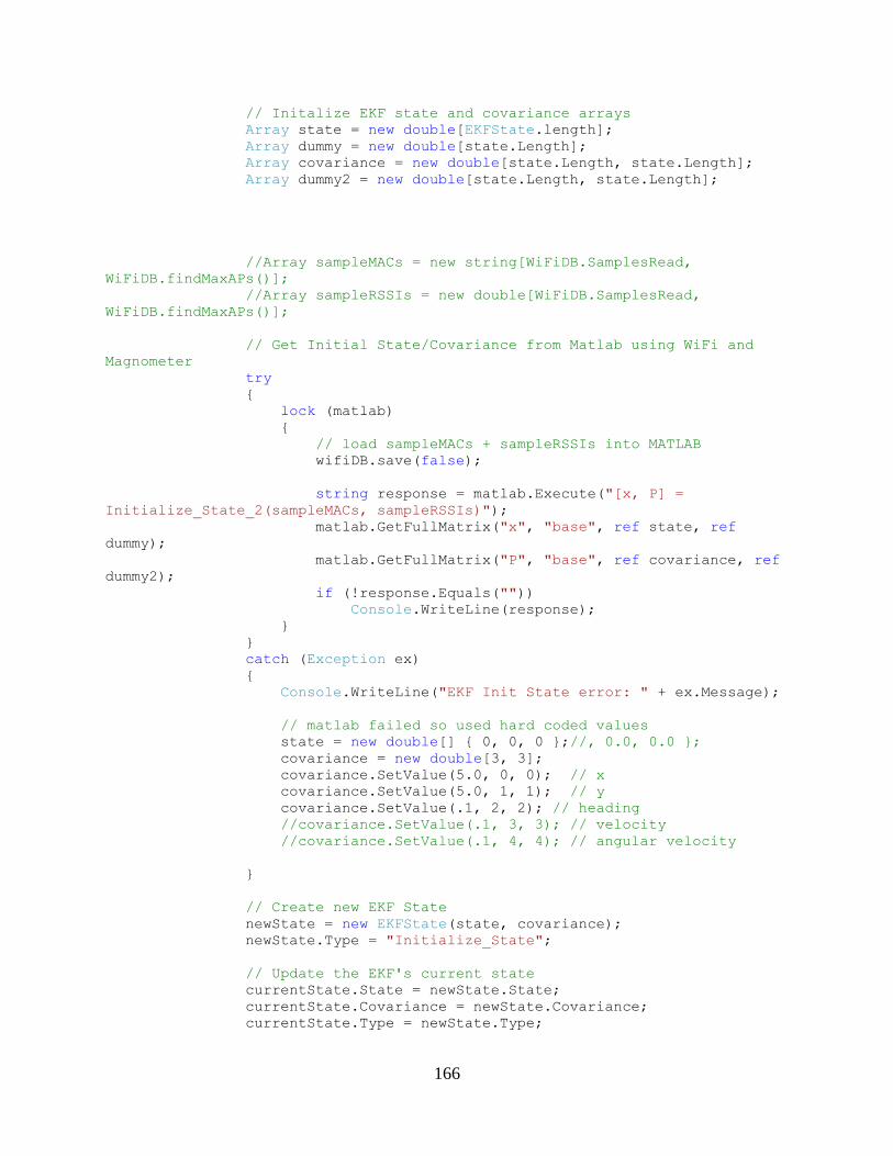
166
// Initalize EKF state and covariance arrays
Array state = new double[EKFState.length];
Array dummy = new double[state.Length];
Array covariance = new double[state.Length, state.Length];
Array dummy2 = new double[state.Length, state.Length];
//Array sampleMACs = new string[WiFiDB.SamplesRead,
WiFiDB.findMaxAPs()];
//Array sampleRSSIs = new double[WiFiDB.SamplesRead,
WiFiDB.findMaxAPs()];
// Get Initial State/Covariance from Matlab using WiFi and
Magnometer
try
{
lock (matlab)
{
// load sampleMACs + sampleRSSIs into MATLAB
wifiDB.save(false);
string response = matlab.Execute("[x, P] =
Initialize_State_2(sampleMACs, sampleRSSIs)");
matlab.GetFullMatrix("x", "base", ref state, ref
dummy);
matlab.GetFullMatrix("P", "base", ref covariance, ref
dummy2);
if (!response.Equals(""))
Console.WriteLine(response);
}
}
catch (Exception ex)
{
Console.WriteLine("EKF Init State error: " + ex.Message);
// matlab failed so used hard coded values
state = new double[] { 0, 0, 0 };//, 0.0, 0.0 };
covariance = new double[3, 3];
covariance.SetValue(5.0, 0, 0); // x
covariance.SetValue(5.0, 1, 1); // y
covariance.SetValue(.1, 2, 2); // heading
//covariance.SetValue(.1, 3, 3); // velocity
//covariance.SetValue(.1, 4, 4); // angular velocity
}
// Create new EKF State
newState = new EKFState(state, covariance);
newState.Type = "Initialize_State";
// Update the EKF's current state
currentState.State = newState.State;
currentState.Covariance = newState.Covariance;
currentState.Type = newState.Type;
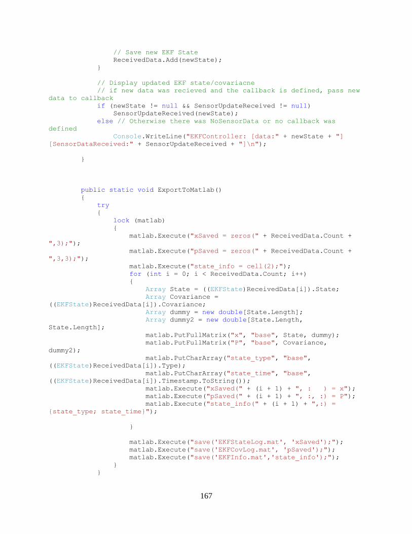
167
// Save new EKF State
ReceivedData.Add(newState);
}
// Display updated EKF state/covariacne
// if new data was recieved and the callback is defined, pass new
data to callback
if (newState != null && SensorUpdateReceived != null)
SensorUpdateReceived(newState);
else // Otherwise there was NoSensorData or no callback was
defined
Console.WriteLine("EKFController: [data:" + newState + "]
[SensorDataReceived:" + SensorUpdateReceived + "]\n");
}
public static void ExportToMatlab()
{
try
{
lock (matlab)
{
matlab.Execute("xSaved = zeros(" + ReceivedData.Count +
",3);");
matlab.Execute("pSaved = zeros(" + ReceivedData.Count +
",3,3);");
matlab.Execute("state_info = cell(2);");
for (int i = 0; i < ReceivedData.Count; i++)
{
Array State = ((EKFState)ReceivedData[i]).State;
Array Covariance =
((EKFState)ReceivedData[i]).Covariance;
Array dummy = new double[State.Length];
Array dummy2 = new double[State.Length,
State.Length];
matlab.PutFullMatrix("x", "base", State, dummy);
matlab.PutFullMatrix("P", "base", Covariance,
dummy2);
matlab.PutCharArray("state_type", "base",
((EKFState)ReceivedData[i]).Type);
matlab.PutCharArray("state_time", "base",
((EKFState)ReceivedData[i]).Timestamp.ToString());
matlab.Execute("xSaved(" + (i + 1) + ", : ) = x");
matlab.Execute("pSaved(" + (i + 1) + ", :, :) = P");
matlab.Execute("state_info(" + (i + 1) + ",:) =
{state_type; state_time}");
}
matlab.Execute("save('EKFStateLog.mat', 'xSaved');");
matlab.Execute("save('EKFCovLog.mat', 'pSaved');");
matlab.Execute("save('EKFInfo.mat','state_info');");
}
}
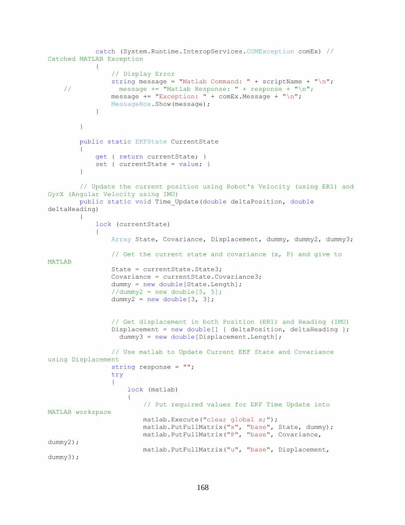
168
catch (System.Runtime.InteropServices.COMException comEx) //
Catched MATLAB Exception
{
// Display Error
string message = "Matlab Command: " + scriptName + "\n";
// message += "Matlab Response: " + response + "\n";
message += "Exception: " + comEx.Message + "\n";
MessageBox.Show(message);
}
}
public static EKFState CurrentState
{
get { return currentState; }
set { currentState = value; }
}
// Update the current position using Robot's Velocity (using ER1) and
GyrX (Angular Velocity using IMU)
public static void Time_Update(double deltaPosition, double
deltaHeading)
{
lock (currentState)
{
Array State, Covariance, Displacement, dummy, dummy2, dummy3;
// Get the current state and covariance (x, P) and give to
MATLAB
State = currentState.State3;
Covariance = currentState.Covariance3;
dummy = new double[State.Length];
//dummy2 = new double[5, 5];
dummy2 = new double[3, 3];
// Get displacement in both Position (ER1) and Heading (IMU)
Displacement = new double[] { deltaPosition, deltaHeading };
dummy3 = new double[Displacement.Length];
// Use matlab to Update Current EKF State and Covariance
using Displacement
string response = "";
try
{
lock (matlab)
{
// Put required values for EKF Time Update into
MATLAB workspace
matlab.Execute("clear global x;");
matlab.PutFullMatrix("x", "base", State, dummy);
matlab.PutFullMatrix("P", "base", Covariance,
dummy2);
matlab.PutFullMatrix("u", "base", Displacement,
dummy3);
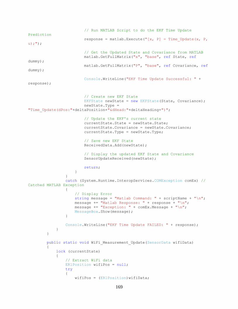
169
// Run MATLAB Script to do the EKF Time Update
Prediction
response = matlab.Execute("[x, P] = Time_Update(x, P,
u);");
// Get the Updated State and Covariance from MATLAB
matlab.GetFullMatrix("x", "base", ref State, ref
dummy);
matlab.GetFullMatrix("P", "base", ref Covariance, ref
dummy);
Console.WriteLine("EKF Time Update Successful: " +
response);
// Create new EKF State
EKFState newState = new EKFState(State, Covariance);
newState.Type =
"Time_Update(dPos:"+deltaPosition+"&dHead:"+deltaHeading+")";
// Update the EKF's current state
currentState.State = newState.State;
currentState.Covariance = newState.Covariance;
currentState.Type = newState.Type;
// Save new EKF State
ReceivedData.Add(newState);
// Display the updated EKF State and Covariance
SensorUpdateReceived(newState);
return;
}
}
catch (System.Runtime.InteropServices.COMException comEx) //
Catched MATLAB Exception
{
// Display Error
string message = "Matlab Command: " + scriptName + "\n";
message += "Matlab Response: " + response + "\n";
message += "Exception: " + comEx.Message + "\n";
MessageBox.Show(message);
}
Console.WriteLine("EKF Time Update FAILED: " + response);
}
}
public static void WiFi_Measurement_Update(SensorData wifiData)
{
lock (currentState)
{
// Extract WiFi data
ER1Position wifiPos = null;
try
{
wifiPos = (ER1Position)wifiData;
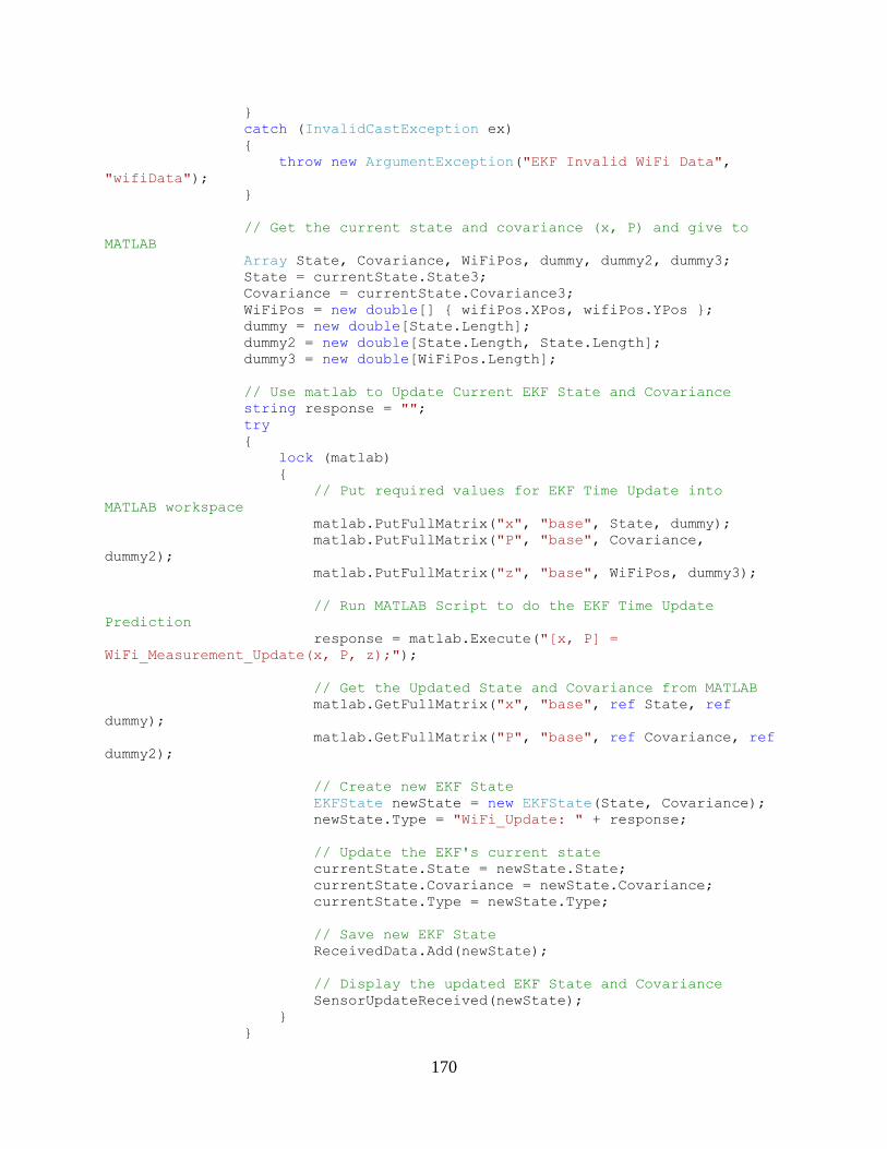
170
}
catch (InvalidCastException ex)
{
throw new ArgumentException("EKF Invalid WiFi Data",
"wifiData");
}
// Get the current state and covariance (x, P) and give to
MATLAB
Array State, Covariance, WiFiPos, dummy, dummy2, dummy3;
State = currentState.State3;
Covariance = currentState.Covariance3;
WiFiPos = new double[] { wifiPos.XPos, wifiPos.YPos };
dummy = new double[State.Length];
dummy2 = new double[State.Length, State.Length];
dummy3 = new double[WiFiPos.Length];
// Use matlab to Update Current EKF State and Covariance
string response = "";
try
{
lock (matlab)
{
// Put required values for EKF Time Update into
MATLAB workspace
matlab.PutFullMatrix("x", "base", State, dummy);
matlab.PutFullMatrix("P", "base", Covariance,
dummy2);
matlab.PutFullMatrix("z", "base", WiFiPos, dummy3);
// Run MATLAB Script to do the EKF Time Update
Prediction
response = matlab.Execute("[x, P] =
WiFi_Measurement_Update(x, P, z);");
// Get the Updated State and Covariance from MATLAB
matlab.GetFullMatrix("x", "base", ref State, ref
dummy);
matlab.GetFullMatrix("P", "base", ref Covariance, ref
dummy2);
// Create new EKF State
EKFState newState = new EKFState(State, Covariance);
newState.Type = "WiFi_Update: " + response;
// Update the EKF's current state
currentState.State = newState.State;
currentState.Covariance = newState.Covariance;
currentState.Type = newState.Type;
// Save new EKF State
ReceivedData.Add(newState);
// Display the updated EKF State and Covariance
SensorUpdateReceived(newState);
}
}
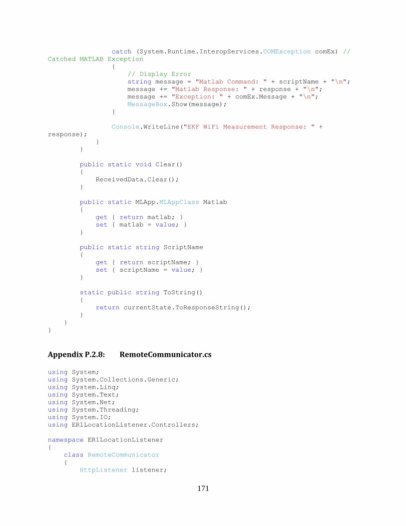
171
catch (System.Runtime.InteropServices.COMException comEx) //
Catched MATLAB Exception
{
// Display Error
string message = "Matlab Command: " + scriptName + "\n";
message += "Matlab Response: " + response + "\n";
message += "Exception: " + comEx.Message + "\n";
MessageBox.Show(message);
}
Console.WriteLine("EKF WiFi Measurement Response: " +
response);
}
}
public static void Clear()
{
ReceivedData.Clear();
}
public static MLApp.MLAppClass Matlab
{
get { return matlab; }
set { matlab = value; }
}
public static string ScriptName
{
get { return scriptName; }
set { scriptName = value; }
}
static public string ToString()
{
return currentState.ToResponseString();
}
}
}
Appendix P.2.8: RemoteCommunicator.cs
using System;
using System.Collections.Generic;
using System.Linq;
using System.Text;
using System.Net;
using System.Threading;
using System.IO;
using ER1LocationListener.Controllers;
namespace ER1LocationListener
{
class RemoteCommunicator
{
HttpListener listener;

172
string baseFolder;
Thread workerThread;
// Location Sensing Hardware Controllers
ER1Controller er1Controller;
IMUController imuSensor;
WiFiController wifiSensor;
CustomAlgorithm positionAlgo;
MLApp.MLAppClass matlab;
int fails;
Models.WiFiData wifiData = null;
public RemoteCommunicator(ref ER1Controller er1Controller, ref
IMUController imuController, ref WiFiController wifiSensor, ref
CustomAlgorithm positionAlgo)
{
fails = 0;
// Location Sensing Hardware Controllers
this.er1Controller = er1Controller;
this.imuSensor = imuController;
this.wifiSensor = wifiSensor;
this.positionAlgo = positionAlgo;
// Create Matlab
try
{
matlab = new MLApp.MLAppClass();
}
catch (Exception ex) { Console.WriteLine("Cannot Start
Matlab..."); }
bool camera_started = camera_connect();
if (!camera_started)
{
Console.WriteLine("COULD NOT INIT CAMERA");
Console.WriteLine("Trying to close and reconnect");
if (camera_disconnect())
if (!camera_connect()) Console.WriteLine("STILL COULD NOT
INIT CAMERA");
}
ThreadPool.SetMaxThreads(1, 1);
ThreadPool.SetMinThreads(1, 1);
// Create the HTTP Listener to accept requests from the network
listener = new HttpListener();
listener.Prefixes.Add("http://127.0.0.1/"); // listen on local
loopback
listener.Prefixes.Add("http://localhost/"); // listen on
localhost
listener.Prefixes.Add("http://*/"); // listen on localhost
IPAddress[] addresses =
Dns.GetHostAddresses(Dns.GetHostName());// listen on ip address
for (int i = 0; i < addresses.Length; i++)
{
string address = addresses[i].ToString();
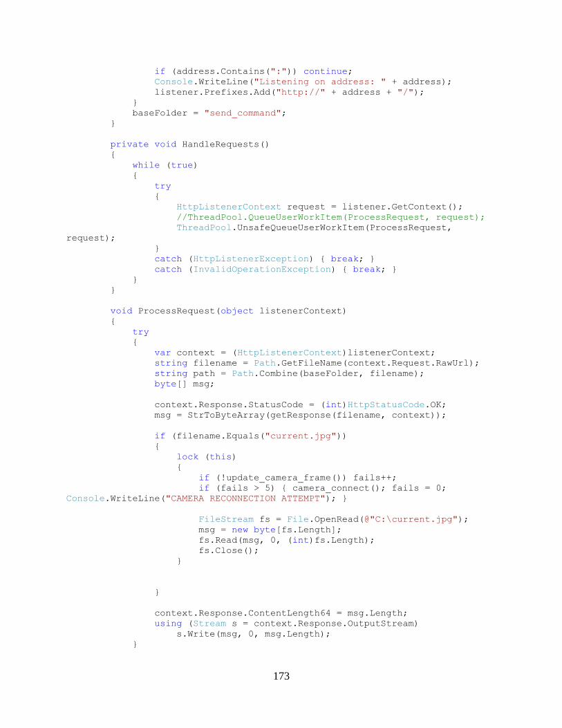
173
if (address.Contains(":")) continue;
Console.WriteLine("Listening on address: " + address);
listener.Prefixes.Add("http://" + address + "/");
}
baseFolder = "send_command";
}
private void HandleRequests()
{
while (true)
{
try
{
HttpListenerContext request = listener.GetContext();
//ThreadPool.QueueUserWorkItem(ProcessRequest, request);
ThreadPool.UnsafeQueueUserWorkItem(ProcessRequest,
request);
}
catch (HttpListenerException) { break; }
catch (InvalidOperationException) { break; }
}
}
void ProcessRequest(object listenerContext)
{
try
{
var context = (HttpListenerContext)listenerContext;
string filename = Path.GetFileName(context.Request.RawUrl);
string path = Path.Combine(baseFolder, filename);
byte[] msg;
context.Response.StatusCode = (int)HttpStatusCode.OK;
msg = StrToByteArray(getResponse(filename, context));
if (filename.Equals("current.jpg"))
{
lock (this)
{
if (!update_camera_frame()) fails++;
if (fails > 5) { camera_connect(); fails = 0;
Console.WriteLine("CAMERA RECONNECTION ATTEMPT"); }
FileStream fs = File.OpenRead(@"C:\current.jpg");
msg = new byte[fs.Length];
fs.Read(msg, 0, (int)fs.Length);
fs.Close();
}
}
context.Response.ContentLength64 = msg.Length;
using (Stream s = context.Response.OutputStream)
s.Write(msg, 0, msg.Length);
}
174
catch (Exception ex) { Console.WriteLine("Request error: " + ex);
}
}
public bool camera_connect()
{
if (matlab == null) return false;
matlab.Execute(@"addpath 'C:\Program
Files\MATLAB\R2006b\toolbox\ERToolkits'");
matlab.Execute(@"addpath 'C:\Program
Files\MATLAB\R2006b\toolbox\tcp_udp_ip'");
string msg = matlab.Execute(@"erInit");
// System.Windows.Forms.MessageBox.Show(msg);
if (msg.Contains("server is busy"))
return false;
return true;
}
public bool camera_disconnect()
{
if (matlab == null) return false;
string msg = matlab.Execute(@"run 'C:\Program
Files\MATLAB\R2006b\toolbox\ERToolkits\erClose'");
// System.Windows.Forms.MessageBox.Show(msg);
if (msg.Contains("closed succesfull"))
return true;
return false;
}
public bool update_camera_frame()
{
string msg = "";
lock (this)
{
try
{
// Request Camera Image from Server
matlab.Execute(@"addpath 'C:\Program
Files\MATLAB\R2006b\toolbox\ERToolkits\'");
msg = matlab.Execute(@"img = erGetImage;");
// If erGetImage response display it
if (!msg.Trim().Equals("")) Console.WriteLine(msg);
// Return false if error getting image
if (msg.Contains("erInit") || msg.Contains("error in") ||
msg.Contains("server error")) return false;
// Write image to file
msg = matlab.Execute(@"imwrite(img, 'c:\current.jpg');");
// If matlab image write has response display it
if (!msg.Trim().Equals("")) Console.WriteLine(msg);
175
}
catch (Exception ex)
{
Console.WriteLine("CAM Excepction: " + ex.Message);
}
return true;
}
}
string getResponse(string request, HttpListenerContext context)
{
request = request.Replace("%20", " "); // replace ASCII code for
space with a space
if (request.Equals("favicon.ico")) return "";
// Declare the response for the request
string response = "";
// Display Status Page containg the status of
if(request.Equals("status"))
{
response = "ER1 Remote Access running...\n\n";
response += er1Controller.ToString() + "\n" ;
response += imuSensor.ToString() + "\n";
response += "\nTimestamp: " + DateTime.Now + "\n";
return response;
}
if (request.Equals("wifiscan"))
{
// Read wifiscan data from POST web request from inSSIDer
Stream readStream = context.Request.InputStream;
byte[] data = new byte[context.Request.ContentLength64];
readStream.Read(data, 0, data.Length);
// Convert data to string and save for later use
ASCIIEncoding encoding = new ASCIIEncoding();
string wifiScanData = encoding.GetString(data);
// Save current wifidata
lock (wifiSensor)
{
wifiSensor.ReceiveWiFiData(Models.WiFiData.Parse2(wifiScanData));
Console.WriteLine("WiFi found " +
wifiSensor.CurrentWiFiData.Length + " Access Points");
}
} else if(request.Equals("wifiscan_result")) {
// return the last scanned wifidata
return wifiSensor.CurrentWiFiData.ToString();
// ER1 Remote API is Connected request
} else if(request.Equals("isER1Connected")) {
if(er1Controller.connected())
176
return "CONNECTED";
else
return "NOT_CONNECTED";
}
// Handle IMU Rquests
else if (IMUController.handlesRequest(request))
{
// Return the last received IMU Data (Accel,Gyr,Mag, and
Timestamp)
return imuSensor.CurrentData.ToString();
}
// Handle position request (use ER1 if connected,
else if (request.Equals("position")) // OVERRIDE ER1 Positon cmd
for
{
if (!er1Controller.connected()) // Simulation mode when no
connection
{
Models.ER1Position er1Pos =
(Models.ER1Position)er1Controller.CurrentData;
if (Models.SensorData.NoSensorData.Equals(er1Pos))
{
return "Not Connected to ER1 Telnet API";
}
//return "OK " + er1Pos.XPos.ToString("%.1d") + " " +
er1Pos.YPos.ToString("%.1d") + " " + er1Pos.Angle.ToString("%.1d");
return er1Pos.ToResponseString();
}
//return er1Controller.sendCommand(request);
Models.ER1Position curPos =
(Models.ER1Position)er1Controller.CurrentData;
return curPos.ToResponseString();
} else if (request.Equals("er1IMUposition") ){
// Combine ER1 Position and IMU Angle
Models.ER1Position curPosER1 =
(Models.ER1Position)er1Controller.CurrentData;
Models.ER1Position curPosIMU =
(Models.ER1Position)positionAlgo.CurrentData;
Models.ER1Position curPos = new
Models.ER1Position(curPosER1.XPos, curPosER1.YPos, curPosIMU.Angle);
return curPos.ToResponseString();
}
else if (request.Equals("getWiFiPosition"))
{
// Use WiFi x, y and IMU yaw for heading angle
Models.ER1Position curPosWiFi =
(Models.ER1Position)wifiSensor.CurrentData;
if (imuSensor.isUpdating())
{
Models.IMUData curIMUData =
(Models.IMUData)imuSensor.CurrentData;
if (!curIMUData.Equals(Models.SensorData.NoSensorData))
curPosWiFi.Angle = Math.Atan2(curIMUData.MagYVal,
curIMUData.MagXVal);
}
return curPosWiFi.ToResponseString();
}
177
else if (request.Equals("getEKFPosition"))
{
try
{
Models.EKFState currentState =
(Models.EKFState)EKFAlgorithmClass.CurrentState;
return currentState.ToResponseString();
}
catch (Exception ex)
{
Console.WriteLine("No EKF State");
return (new Models.ER1Position(0, 0)).ToResponseString();
}
}
else if (request.Equals("customPosition")) // CUSTOM Algorithm
for position
{
if (!positionAlgo.isUpdating())//(!er1Controller.connected()
|| !er1Controller.isUpdating() || !imuSensor.isUpdating())
{
return "NOT_UPDATING_ALL_SENSORS";
}
//positionAlgo.updatePosition(); // Updating at TimeInterval
now
return positionAlgo.ToString(); // Gives out latest position
calculated from algo
}
else if (request.Equals("resetCustomPosition"))
{
positionAlgo.resetPosition();
return positionAlgo.ToString();
}
else if (ER1Controller.handlesRequest(request)) // Handle ER1
Command requests (mov, position, etc)
{
if (!er1Controller.connected()) return "Not Connected to ER1
Telnet API";
return er1Controller.sendCommand(request);
}
else if (request == "getPosition")
{
// Simulation built into er1Controller for no connectionz
return er1Controller.CurrentData.ToString();
/*
// Make sure connected to ER1 Telnet Remote API
if (!er1Controller.connected()) return "Not Connected to ER1
Telnet API";
// Show all recent received data
string str = "ER1 Position: \n";
str += er1Controller.CurrentData.ToString() + "\n";
//str += "IMU Data: \n" + imuSensor.CurrentData.ToString() +
"\n;
return str;
178
*/
// WILL OVERRIDE WITH ALGORITHM AND RETURN END RESULT
POSITION
// FOR NOW FORWARD ALONG TO ER1 CONTROLLER TO USE THEIR
INTERNAL POSITION ALGORITHM
//return ER1Controller.sendCommand("position");
}
return "UNKOWN_REQUEST";
}
public bool Start()
{
// Start the HTTP Listener to receive commands
try
{
listener.Start();
}
catch (HttpListenerException ex) // Handle error starting http
server
{
System.Windows.Forms.MessageBox.Show(ex.Message, "HTTP Server
Exception");
return false;
}
try
{
// Stop Worker Thread if already running And Create and Start
new worker thread
if (workerThread != null &&
workerThread.ThreadState.Equals(ThreadState.Running)) workerThread.Abort();
workerThread = new Thread(new ThreadStart(HandleRequests));
workerThread.Start();
}
catch (ThreadStateException ex)
{
System.Windows.Forms.MessageBox.Show("Message: " +
ex.Message, "Server Start Exception");
return false;
}
return true;
}
public void Stop()
{
workerThread.Abort();
listener.Stop();
}
public static byte[] StrToByteArray(string str)
{
System.Text.ASCIIEncoding encoding = new
System.Text.ASCIIEncoding();
179
return encoding.GetBytes(str);
}
public void setER1Controller(ER1Controller er1Controller)
{
this.er1Controller = er1Controller;
}
public ER1Controller getER1Controller()
{
return er1Controller;
}
}
}
Appendix P.2.9: Form1.cs
using System;
using System.Collections.Generic;
using System.ComponentModel;
using System.Data;
using System.Drawing;
using System.Linq;
using System.Text;
using System.Windows.Forms;
using ER1LocationListener.Controllers;
using System.Management;
using System.Management.Instrumentation;
using WIA;
namespace ER1LocationListener
{
public partial class Form1 : Form
{
delegate void SafeSetTextCallback(TextBox button, string text);
delegate void RenameButtonCallback(Button button, string text);
delegate void ListAddDataCallback(ListBox listData, Models.SensorData
data);
delegate void DataGridAddRowCallback(DataGridView dataGridView,
Models.SensorData data);
delegate void DataGridAddObjectRowCallback(DataGridView dataGridView,
object[] data);
/*
delegate void SetTextCallback(string text);
delegate void UpdateListCallback(Models.SensorData data);
*/
private RemoteCommunicator rc;
private ER1Controller er1Controller;
private IMUController imuSensor;
private WiFiController wifiSensor;
private SonarController sonarSensor;
private CustomAlgorithm positionAlgo;
//private EKFAlgorithm EKFAlgo;

180
private WiFiDB wifiDB;
public Form1()
{
InitializeComponent();
// Initialize Parameters
int TimeInterval = 1000;// 500; // time in milliseconds to wait
between sensor data updates
string hostname = "127.0.0.1";
int port = 9600;
// Initialize WiFiDB
wifiDB = new WiFiDB(txtNumLogged, this);
// Initialize Sensor Controllers
er1Controller = new ER1Controller(hostname, port, 500,
btnStartUpdatingER1); // get updated ER1Position from ER1 Remote API every
1000 milliseconds
imuSensor = new IMUController(1000, btnStartUpdatingIMU, ref
er1Controller); // get updated IMUData from IMU every 1000 milliseconds
wifiSensor = new WiFiController(5000, btnStartUpdatingWiFi,
wifiDB);
sonarSensor = new SonarController(1000, btnStartUpdatingSonar);
positionAlgo = new CustomAlgorithm(ref er1Controller, ref
imuSensor, TimeInterval, btnStartUpdatingPosition);
//EKFAlgo = new EKFAlgorithm(100, btnStartUpdatingEKF);
EKFAlgorithmClass.InitEKF();
// Set Handlers for received data
er1Controller.SensorUpdateReceived = this.ER1PositionReceived;
imuSensor.SensorUpdateReceived = this.IMUUpdateReceived;
wifiSensor.SensorUpdateReceived = this.WiFiUpdateReceived;
sonarSensor.SensorUpdateReceived = this.SonarUpdateReceived;
positionAlgo.SensorUpdateReceived = this.PositionUpdateRecieved;
//EKFAlgo.SensorUpdateReceived = this.EKFUpdateRecieved;
EKFAlgorithmClass.SensorUpdateReceived = this.EKFUpdateRecieved;
// Initialize HTTP Remote Interface
rc = new RemoteCommunicator(ref er1Controller, ref imuSensor, ref
wifiSensor, ref positionAlgo);
Timer frameTimer = new Timer();
frameTimer.Interval = 500;
frameTimer.Tick += new EventHandler(frameTimer_Tick);
//frameTimer.Start();
}
public void camera() {
try
{
string cameraDev = "iRez";
//CommonDialogClass class1 = new CommonDialogClass();
////WIA.ImageFile image =
class1.ShowAcquireImage(WiaDeviceType.UnspecifiedDeviceType,
181
WiaImageIntent.ColorIntent, WiaImageBias.MinimizeSize,
FormatID.wiaFormatJPEG, false, true, true);
//Device d =
class1.ShowSelectDevice(WiaDeviceType.CameraDeviceType, true, false);
DeviceManager manager = new DeviceManagerClass();
Device d = null;
foreach (DeviceInfo info in manager.DeviceInfos)
{
if (info.DeviceID == cameraDev)
{
d = info.Connect();
break;
}
}
Item item =
d.ExecuteCommand(CommandID.wiaCommandTakePicture);
foreach (string format in item.Formats)
{
WIA.ImageFile imageFile = item.Transfer(format) as
WIA.ImageFile;
string filename = @"c:\current.jpg";
if (string.IsNullOrEmpty(filename) == false)
{
imageFile.SaveFile(filename);
}
}
}
catch (Exception e)
{
Console.WriteLine(e.Message);
Console.WriteLine(e.StackTrace);
}
/*
CommonDialog cm = new CommonDialog();
using System.De
Device d;
WIAVIDEOLib.WiaVideoClass wvc = new WIAVIDEOLib.WiaVideoClass();
wvc.CreateVideoByDevNum(*/
}
void frameTimer_Tick(object sender, EventArgs e)
{
btnUpdateImage_Click(sender, e);
}
private void ER1PositionReceived(Models.SensorData ER1Position)
{
// Adds ER1Postion to ER1 Data Grid View
SafeDataGridAddRow(grdER1Position, ER1Position);
// Check Sensor Updating was Stopped
if (ER1Position.Equals(Models.SensorData.SensorUpdatingStopped))
182
SafeRenameButton(btnStartUpdatingER1, "Start Updating ER1");
// Update UI
}
private void IMUUpdateReceived(Models.SensorData imuData)
{
// Check Sensor Updating was Stopped
if (imuData.Equals(Models.SensorData.SensorUpdatingStopped))
SafeRenameButton(btnStartUpdatingIMU, "Start Updating IMU");
// Adds IMU Data to IMU Data Grid View
SafeDataGridAddRow(dgvIMUData, imuData);
}
private void WiFiUpdateReceived(Models.SensorData wifiData)
{
// Check Sensor Updating was Stopped
if (wifiData.Equals(Models.SensorData.SensorUpdatingStopped))
SafeRenameButton(btnStartUpdatingWiFi, "Stop Updating WiFi");
// Adds WiFi Data to WiFi Data Grid View
SafeDataGridAddRow(dgvWiFiData, wifiData);
try
{
EKFAlgorithmClass.WiFi_Measurement_Update(wifiData);
}
catch (ArgumentException ex)
{
Console.WriteLine("WiFi Update Received but failed updating
EKF: " + ex.Message);
}
}
private void SonarUpdateReceived(Models.SensorData sonarData)
{
// Check Sensor Updating was Stopped
if (sonarData.Equals(Models.SensorData.SensorUpdatingStopped))
SafeRenameButton(btnStartUpdatingIMU, "Stop Updating WiFi");
// Adds Sensor Data to Sensor Data Grid View
SafeDataGridAddRow(dgvSonarData, sonarData);
}
// Handles receiving new positions from custom algorithm
private void PositionUpdateRecieved(Models.SensorData position)
{
// Adds ER1Postion to Positioning Algorithm Data Grid View
SafeDataGridAddRow(dgvAlgorithm, position);
/*
// Adds ER1Postion to ER1 Data Grid View
// SafeDataGridAddRow(dgvAlgorithm, position);
if (dgvAlgorithm.InvokeRequired)
{
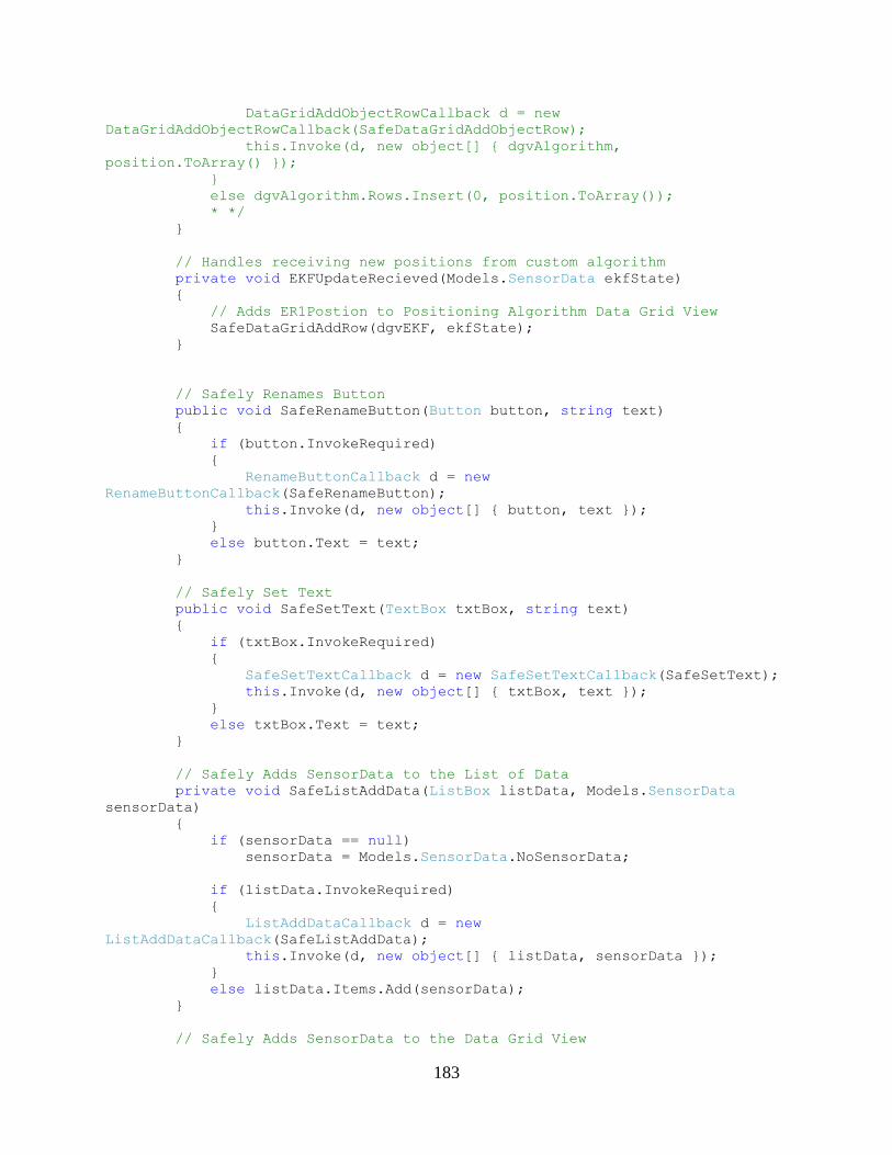
183
DataGridAddObjectRowCallback d = new
DataGridAddObjectRowCallback(SafeDataGridAddObjectRow);
this.Invoke(d, new object[] { dgvAlgorithm,
position.ToArray() });
}
else dgvAlgorithm.Rows.Insert(0, position.ToArray());
* */
}
// Handles receiving new positions from custom algorithm
private void EKFUpdateRecieved(Models.SensorData ekfState)
{
// Adds ER1Postion to Positioning Algorithm Data Grid View
SafeDataGridAddRow(dgvEKF, ekfState);
}
// Safely Renames Button
public void SafeRenameButton(Button button, string text)
{
if (button.InvokeRequired)
{
RenameButtonCallback d = new
RenameButtonCallback(SafeRenameButton);
this.Invoke(d, new object[] { button, text });
}
else button.Text = text;
}
// Safely Set Text
public void SafeSetText(TextBox txtBox, string text)
{
if (txtBox.InvokeRequired)
{
SafeSetTextCallback d = new SafeSetTextCallback(SafeSetText);
this.Invoke(d, new object[] { txtBox, text });
}
else txtBox.Text = text;
}
// Safely Adds SensorData to the List of Data
private void SafeListAddData(ListBox listData, Models.SensorData
sensorData)
{
if (sensorData == null)
sensorData = Models.SensorData.NoSensorData;
if (listData.InvokeRequired)
{
ListAddDataCallback d = new
ListAddDataCallback(SafeListAddData);
this.Invoke(d, new object[] { listData, sensorData });
}
else listData.Items.Add(sensorData);
}
// Safely Adds SensorData to the Data Grid View

184
private void SafeDataGridAddRow(DataGridView dataGridView,
Models.SensorData sensorData)
{
if (sensorData == null) sensorData =
Models.SensorData.NoSensorData;
if (dataGridView.InvokeRequired)
{
DataGridAddRowCallback d = new
DataGridAddRowCallback(SafeDataGridAddRow);
this.Invoke(d, new object[] { dataGridView,
(Models.SensorData)sensorData });
}
else dataGridView.Rows.Insert(0, sensorData.ToArray());
//else dataGridView.Rows.Add(sensorData.ToArray());
}
private void SafeDataGridAddObjectRow(DataGridView dataGridView,
object[] data)
{
if (data == null) return;
if (dataGridView.InvokeRequired)
{
DataGridAddRowCallback d = new
DataGridAddRowCallback(SafeDataGridAddRow);
this.Invoke(d, new object[] { dataGridView, data });
}
else dataGridView.Rows.Insert(0, data);
//else dataGridView.Rows.Add(sensorData.ToArray());
}
private void btnStart_Click(object sender, EventArgs e)
{
Button btnStart = (Button)sender;
if (btnStart.Text == "Start")
{
// Start remote communicator and update button if successfull
if(rc.Start())
btnStart.Text = "Stop";
}
else if (btnStart.Text == "Stop")
{
rc.Stop();
btnStart.Text = "Start";
}
}
private void btnER1Connect_Click(object sender, EventArgs e)
{
if (btnER1Connect.Text == "Connect")
{
string ipAddress = txtER1IPAddress.Text;
int port = int.Parse(txtER1Port.Text);
er1Controller.Connect(ipAddress, port);
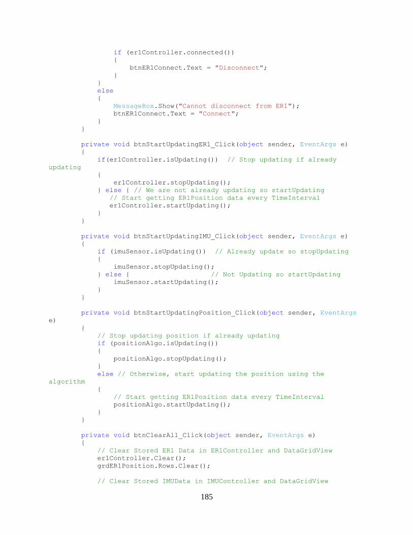
185
if (er1Controller.connected())
{
btnER1Connect.Text = "Disconnect";
}
}
else
{
MessageBox.Show("Cannot disconnect from ER1");
btnER1Connect.Text = "Connect";
}
}
private void btnStartUpdatingER1_Click(object sender, EventArgs e)
{
if(er1Controller.isUpdating()) // Stop updating if already
updating
{
er1Controller.stopUpdating();
} else { // We are not already updating so startUpdating
// Start getting ER1Position data every TimeInterval
er1Controller.startUpdating();
}
}
private void btnStartUpdatingIMU_Click(object sender, EventArgs e)
{
if (imuSensor.isUpdating()) // Already update so stopUpdating
{
imuSensor.stopUpdating();
} else { // Not Updating so startUpdating
imuSensor.startUpdating();
}
}
private void btnStartUpdatingPosition_Click(object sender, EventArgs
e)
{
// Stop updating position if already updating
if (positionAlgo.isUpdating())
{
positionAlgo.stopUpdating();
}
else // Otherwise, start updating the position using the
algorithm
{
// Start getting ER1Position data every TimeInterval
positionAlgo.startUpdating();
}
}
private void btnClearAll_Click(object sender, EventArgs e)
{
// Clear Stored ER1 Data in ER1Controller and DataGridView
er1Controller.Clear();
grdER1Position.Rows.Clear();
// Clear Stored IMUData in IMUController and DataGridView
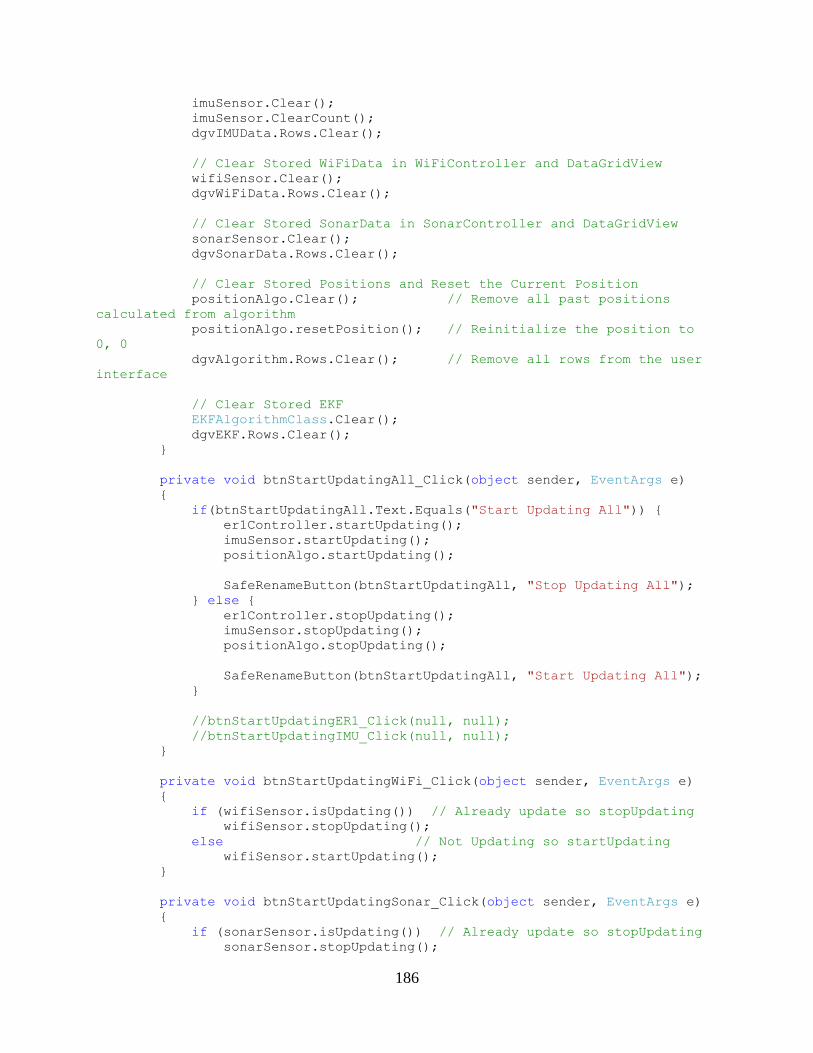
186
imuSensor.Clear();
imuSensor.ClearCount();
dgvIMUData.Rows.Clear();
// Clear Stored WiFiData in WiFiController and DataGridView
wifiSensor.Clear();
dgvWiFiData.Rows.Clear();
// Clear Stored SonarData in SonarController and DataGridView
sonarSensor.Clear();
dgvSonarData.Rows.Clear();
// Clear Stored Positions and Reset the Current Position
positionAlgo.Clear(); // Remove all past positions
calculated from algorithm
positionAlgo.resetPosition(); // Reinitialize the position to
0, 0
dgvAlgorithm.Rows.Clear(); // Remove all rows from the user
interface
// Clear Stored EKF
EKFAlgorithmClass.Clear();
dgvEKF.Rows.Clear();
}
private void btnStartUpdatingAll_Click(object sender, EventArgs e)
{
if(btnStartUpdatingAll.Text.Equals("Start Updating All")) {
er1Controller.startUpdating();
imuSensor.startUpdating();
positionAlgo.startUpdating();
SafeRenameButton(btnStartUpdatingAll, "Stop Updating All");
} else {
er1Controller.stopUpdating();
imuSensor.stopUpdating();
positionAlgo.stopUpdating();
SafeRenameButton(btnStartUpdatingAll, "Start Updating All");
}
//btnStartUpdatingER1_Click(null, null);
//btnStartUpdatingIMU_Click(null, null);
}
private void btnStartUpdatingWiFi_Click(object sender, EventArgs e)
{
if (wifiSensor.isUpdating()) // Already update so stopUpdating
wifiSensor.stopUpdating();
else // Not Updating so startUpdating
wifiSensor.startUpdating();
}
private void btnStartUpdatingSonar_Click(object sender, EventArgs e)
{
if (sonarSensor.isUpdating()) // Already update so stopUpdating
sonarSensor.stopUpdating();

187
else // Not Updating so startUpdating
sonarSensor.startUpdating();
}
private void btnSaveToMatlab_Click(object sender, EventArgs e)
{
positionAlgo.ExportToMatlab();
}
private void btnWZC_Click(object sender, EventArgs e)
{
if (btnWZC.Text.Equals("Start WZC"))
{
System.Diagnostics.Process p =
System.Diagnostics.Process.Start("net", "start wzcsvc");
p.WaitForExit();
btnWZC.Text = "Stop WZC";
}
else
{
System.Diagnostics.Process p =
System.Diagnostics.Process.Start("net", "stop wzcsvc");
p.WaitForExit();
btnWZC.Text = "Start WZC";
}
}
private void btnWZCRefresh_Click(object sender, EventArgs e)
{
System.Diagnostics.ProcessStartInfo psi = new
System.Diagnostics.ProcessStartInfo("net", "start");
psi.RedirectStandardOutput = true;
psi.UseShellExecute = false;
System.Diagnostics.Process p =
System.Diagnostics.Process.Start(psi);
p.WaitForExit();
if (p.HasExited)
{
System.IO.StreamReader sr = p.StandardOutput;
string output = sr.ReadToEnd();
if (output.Contains("Wireless Zero Configuration"))
btnWZC.Text = "Stop WZC";
else
btnWZC.Text = "Start WZC";
}
}
private void btnIMUExportMatlab_Click(object sender, EventArgs e)
{
imuSensor.ExportToMatlab();
}
private void btnWiFiExportMatlab_Click(object sender, EventArgs e)
{
wifiSensor.ExportToMatlab();
}
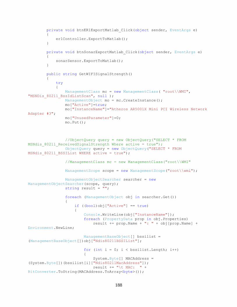
188
private void btnER1ExportMatlab_Click(object sender, EventArgs e)
{
er1Controller.ExportToMatlab();
}
private void btnSonarExportMatlab_Click(object sender, EventArgs e)
{
sonarSensor.ExportToMatlab();
}
public string GetWIFISignalStrength()
{
try
{
ManagementClass mc = new ManagementClass( "root\\WMI",
"MSNDis_80211_BssIdListScan", null );
ManagementObject mo = mc.CreateInstance();
mo["Active"]=true;
mo["InstanceName"]="Atheros AR5001X Mini PCI Wireless Network
Adapter #3";
mo["UnusedParameter"]=0;
mo.Put();
//ObjectQuery query = new ObjectQuery("SELECT * FROM
MSNdis_80211_ReceivedSignalStrength Where active = true");
ObjectQuery query = new ObjectQuery("SELECT * FROM
MSNdis_80211_BSSIList WHERE active = true");
//ManagementClass mc = new ManagementClass("root\\WMI"
ManagementScope scope = new ManagementScope("root\\wmi");
ManagementObjectSearcher searcher = new
ManagementObjectSearcher(scope, query);
string result = "";
foreach (ManagementObject obj in searcher.Get())
{
if ((bool)obj["Active"] == true)
{
Console.WriteLine(obj["InstanceName"]);
foreach (PropertyData prop in obj.Properties)
result += prop.Name + ": " + obj[prop.Name] +
Environment.NewLine;
ManagementBaseObject[] bssilist =
(ManagementBaseObject[])obj["Ndis80211BSSIList"];
for (int i = 0; i < bssilist.Length; i++)
{
System.Byte[] MACAddress =
(System.Byte[])(bssilist[i]["Ndis80211MacAddress"]);
result += "\t MAC: " +
BitConverter.ToString(MACAddress.ToArray<byte>());
189
int RSSI_OFFSET = 121;
UInt32 RSSI =
(UInt32)(bssilist[i]["Ndis80211RSSI"]);
double dBm = 10*Math.Log10(1000.0*RSSI) -
RSSI_OFFSET;
result += "\t RSSI: " +
dBm;//Convert.ToString((UInt32)(bssilist[i]["Ndis80211RSSI"]), 16);
result += Environment.NewLine;
Console.WriteLine((bssilist[i]["Ndis80211RSSI"]).GetType());
// foreach(PropertyData prop in
bssilist[i].Properties)
// result += "\t" + prop.Name + ": " +
bssilist[i][prop.Name] + Environment.NewLine;
}
// result +=
(string)obj["Ndis80211ReceivedSignalStrength"].ToString() +
Environment.NewLine;
result += "END" + Environment.NewLine;
}
}
if (result == "")
{
result = "No active WI-FI adapters found!";
}
return result.Trim();
}
catch (Exception ex)
{
Console.WriteLine(ex.StackTrace);
MessageBox.Show(ex.Message, "Search Error",
MessageBoxButtons.OK, MessageBoxIcon.Error);
return string.Empty;
}
}
public static string getMACString(System.Byte[] mac)
{
string strMAC = "";
foreach (Byte b in mac)
{
strMAC += b.ToString("X").PadLeft(2, '0') + ":";
}
strMAC = strMAC.TrimEnd(':');
return strMAC;
}
public static void ScanAvailableNetworks()
{
ManagementClass mc = new ManagementClass("root\\WMI",
"MSNDis_80211_BssIdListScan", null);
ManagementObject mo = mc.CreateInstance();
mo["Active"] = true;
190
mo["InstanceName"] = "Atheros AR5001X Mini PCI Wireless Network
Adapter #3";
mo["UnusedParameter"] = 0;
mo.Put();
}
public static void GetAvailableNetworks()
{
string result = "";
try
{
ScanAvailableNetworks();
/*Making the search*/
string scope = "root\\WMI";
string query = "SELECT * FROM MSNdis_80211_BSSIList WHERE
active = true";
ManagementObjectSearcher mos = new
ManagementObjectSearcher(scope, query);
ManagementObjectCollection moc = mos.Get();
ManagementObjectCollection.ManagementObjectEnumerator moe =
moc.GetEnumerator();
moe.MoveNext();
moe.MoveNext();
/*Adapter name*/
Console.WriteLine("Adapter: " +
moe.Current.Properties["InstanceName"].Value);
/*Number of available wireless networks*/
Console.WriteLine("Available wireless networks: " +
moe.Current.Properties["NumberOfItems"].Value);
ManagementBaseObject[] objarr =
(ManagementBaseObject[])moe.Current.Properties["Ndis80211BSSIList"].Value;
foreach (ManagementBaseObject queryObj in objarr)
{
/*One SSID per line (SSID = name of nerwork)*/
PropertyData ssid = queryObj.Properties["Ndis80211Ssid"];
PropertyData mac =
queryObj.Properties["Ndis80211MacAddress"];
PropertyData rssi = queryObj.Properties["Ndis80211Rssi"];
string strSSID =
Encoding.ASCII.GetString((System.Byte[])ssid.Value).TrimEnd('\0');
string strMAC =
getMACString((System.Byte[])mac.Value);//BitConverter.ToString((System.Byte[]
)mac.Value);
uint RSSI = (UInt32)(rssi.Value);
int RSSI_OFFSET = 121;
double dBm = 10 * Math.Log10(1.0000 * RSSI) -
RSSI_OFFSET;
if (RSSI == 0) dBm = -130;
result += "MAC: " + strMAC + "\tdBm : " + dBm + "\tRSSI:
" + RSSI.ToString("X").PadLeft(2,'0') + Environment.NewLine;
191
//Console.Write(result);
//Console.WriteLine(ssid.Name + " = " + strSSID + ",
type: " + ssid.Type);
//Console.WriteLine(mac.Name + " = " + strMAC + ", type:
" + mac.Type);
//Console.WriteLine(rssi.Name + " = " + dBm + ", type: "
+ mac.Type);
//Console.WriteLine(Encoding.ASCII.GetString((System.Byte[])(queryObj.Propert
ies["Ndis80211Ssid"].Value)));
/*
* Other info:
* Ndis80211Ssid (Service Set Identifer) (array of uint8) =
byte[]
* Ndis80211MacAddress (array of uint8) = byte[]
* Ndis80211Rssi (Recieved Signal Strength Identifier)
(uint32) (Must be converted to dBm :/)
*/
}
}
catch (ManagementException e)
{
Console.WriteLine("An error occurred while querying for WMI
data: " + e.Message);
}
MessageBox.Show(result);
}
private void btnStartUpdatingEKF_Click(object sender, EventArgs e)
{
Console.WriteLine("START UPDATING EKF Not needed");
}
private void btnInitEKF_Click(object sender, EventArgs e)
{
// Gather 10 wifi samples
wifiDB.Clear();
wifiDB.SamplesToRead = 10;
wifiDB.onAllWiFiSamplesReceived =
EKFAlgorithmClass.Initialize_State_2;
// EKFAlgorithmClass.Initialize_State_2();
}
private void btnEKFExportMatlab_Click(object sender, EventArgs e)
{
EKFAlgorithmClass.ExportToMatlab();
}
private void btnInitCamera_Click(object sender, EventArgs e)
{
192
camera();
return;
imuSensor.Matlab.Execute(@"addpath 'C:\Program
Files\MATLAB\R2006b\toolbox\ERToolkits'");
imuSensor.Matlab.Execute(@"addpath 'C:\Program
Files\MATLAB\R2006b\toolbox\tcp_udp_ip'");
string msg = imuSensor.Matlab.Execute(@"erInit");
MessageBox.Show(msg);
}
private void btnCloseCamera_Click(object sender, EventArgs e)
{
/*
string msg = imuSensor.Matlab.Execute(@"run 'C:\Program
Files\MATLAB\R2006b\toolbox\ERToolkits\erClose'");
*/
//string msg = GetWIFISignalStrength();
//Console.WriteLine(msg);
GetAvailableNetworks();
//MessageBox.Show(msg);
}
private void btnUpdateImage_Click(object sender, EventArgs e)
{
imuSensor.Matlab.Execute(@"addpath 'C:\Program
Files\MATLAB\R2006b\toolbox\ERToolkits\'");
string msg = imuSensor.Matlab.Execute(@"img = erGetImage;
imwrite(img, 'c:\current.jpg');");
Console.WriteLine(msg);
}
private void btnGetWiFi_Click(object sender, EventArgs e)
{
string name = "";
int samples = 0;
try
{
name = txtDBName.Text;
samples = int.Parse(txtNumSamples.Text);
}
catch (Exception ex)
{
MessageBox.Show("Invalid Name or Number of Samples chosen");
return;
}
wifiDB.Name = name;
wifiDB.SamplesToRead = samples;
wifiDB.SamplesRead = 0;
}
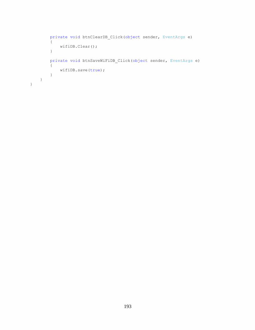
193
private void btnClearDB_Click(object sender, EventArgs e)
{
wifiDB.Clear();
}
private void btnSaveWiFiDB_Click(object sender, EventArgs e)
{
wifiDB.save(true);
}
}
}
194
BIBLIOGRAPHY
1. Miller, L. E., P. F. Wilson, N. P. Bryner, M. H. Francis, J. R. Guerrieri, D. W. Stroup, L.
Klein-Berndt. RFID-Assisted Indoor Localization and Commuication for First
Responders. Tech. 2005. Web.
<http://www.antd.nist.gov/wctg/RFID/ISART06-Assisted-LocCom.pdf>
2. Se, Stephen, David Lowe, and Jim Little. Vision-based Mobile Robot Localization and
Mapping using Scale-Invariant Features. Tech. 2000. Web.
<http://citeseerx.ist.psu.edu/viewdoc/download?doi=10.1.1.62.2166&rep=rep1&type=pdf>
3. Frank, Korbinian, Bernhard Krach, Noel Catterall, and Patrick Robertson. Development
and Evaluation of a Combined WLAN & Inertial Indoor Pedestrian Positioning System.
Working Paper. 2009. Print.
4. Rekleitis, Ioannis M. A Particle Filter Tutorial for Mobile Robot Localization TR-CIM-
04-02. Tech. 2003. Web. <http://www.cse.buffalo.edu/~peter/refs/DataAssimilation/GenRefsTutorials/particletutorial.pdf>
5. Pahlavan, Kaveh, Xinrong Li, and Juha-Pekka Makela. Indoor Geolocation Science and
Technology. Tech. Feb. 2002. Web. <http://www.cwins.wpi.edu/publications/00983917.pdf>
6. Roos, Teemu, Petri Myllymaki, Henry Tirri, Pauli Misikangas, and Juha Sievanen. "A
Probabilistic Approach to WLAN User Location Estimation." International Journal of
Wireless Information Networks 9.3 (2002). Web.
<Http://www.springerlink.com/content/rdtrq0rpptf1geby/fulltext.pdf.>
7. Riisgaard, Soren, and Morten Rufus Blas. SLAM for Dummies, A Tutorial Approach to
Simultaneous Localization and Mapping. Rep. Print.
8. Ralf, Solomon, Matthias Schneider, and Daniel Wehden. Low-Cost Optical Indoor
Localization System for Mobile Objects without Image Processing. Rep. Web.
<http://www.imd.uni-rostock.de/veroeff/psd-salomon-06.pdf>.
9. Chitra, Pushkaraj Pradeep, and Kaveh Pahlavan. Localization Algorithms and Dynamic
Channel Behavior for Urban Geo-location. Rep. Print.
10. Kiriy, Eygeni, and Martin Buehler. Three-State Extended Kalman Filter for Mobile Robot
Localization. Tech. 12 Apr. 2002. Web. <http://www.cim.mcgill.ca/~kiriy/publications/eKf-
3state.pdf>.
11. Welch, Greg, and Gary Bishop. An Introduction to the Kalman Filter. Publication. 24
July 2006. Web. <http://citeseerx.ist.psu.edu/viewdoc/download?doi=10.1.1.79.6578&re
p=rep1&type=pdf>.
195
12. P. Bahl and V.N. Padmanabhan, "RADAR: An in-Building RF-based user location and
tracking system," Proc. Of IEEE INFOCOM 2000. vol. 2, pp. 775 - 784 , March 2000.
<http://research.microsoft.com/en-us/people/padmanab/infocom2000.pdf>
13. Xsens Technologies. Magnetic Field Mapper MT Manager Add on User Manual. 2008.
Print.
14. Xsens Technologies. MTi and MTx User Manual and Technical Documentation. 2008.
Print.
15. Xsens Technologies. MT Manager User Manual. Rep. 2008. Print.
16. Evolution Robotics. ER1 User Manual. Print.