HYBRID FUZZY LOGIC AND PID CONTROLLER FOR PH NEUTRALIZATION PILOT PLANT
14
International Journal of Fuzzy Logic Systems (IJFLS) Vol.3, No2, April 2013 DOI : 10.5121/ijfls.2013.3201 1 HYBRID FUZZY LOGIC AND PID CONTROLLER FOR PH NEUTRALIZATION PILOT PLANT Oumair Naseer 1 , Atif Ali Khan 2 1,2 School of Engineering, University of Warwick, Coventry, UK, [email protected] [email protected] ABSTRACT Use of Control theory within process control industries has changed rapidly due to the increase complexity of instrumentation, real time requirements, minimization of operating costs and highly nonlinear characteristics of chemical process. Previously developed process control technologies which are mostly based on a single controller are not efficient in terms of signal transmission delays, processing power for computational needs and signal to noise ratio. Hybrid controller with efficient system modelling is essential to cope with the current challenges of process control in terms of control performance. This paper presents an optimized mathematical modelling and advance hybrid controller (Fuzzy Logic and PID) design along with practical implementation and validation of pH neutralization pilot plant. This procedure is particularly important for control design and automation of Physico-chemical systems for process control industry. KEYWORDS Hybrid Control, PID Controller, Fuzzy Logic Controller, pH Neutralization Pilot Plant, Process Control and Automation Technologies, Control Theory and Applications. 1. INTRODUCTION Control system design for neutralization pilot plant has a long history, due to its non-linear characteristics, uncertainty and large number of requirements from environment legislation which revised constantly. Most of the classical control techniques are developed on the bases of linear theory. When these techniques are applied to the chemical systems having kinetic reactions and thermodynamic relationships, they do not provide the adequate system performance and hence fails to capture the entire operating range. neutralization process mainly consists of measurement of an acid-base chemical reaction in which hydrogen ions and hydroxide ions are neutralized or combined with each other to form water, while the other ions involved remained unchanged. Acid is a substance that ionises in water to produce hydrogen ions and base is a substance which ionises in water to produce hydroxyl ions. The characteristics of acid-base neutralization reaction are normally represented by a titration curve. Fig.1 below provides the information about the equilibrium point [1, 2], the type of acid-based (strong/weak) involved and the total volume or amount of substances involved at the end of the titration process. The S- shaped curve shown in Fig. 1 depends on the concentration and composition of acid and based used in the process reaction. It can be seen that at value of 7, a small change in input produces a large change in output, which provides the significance of controlling Value [3, 33, and 35].
-
Upload
ijfls -
Category
Technology
-
view
597 -
download
3
description
Use of Control theory within process control industries has changed rapidly due to the increase complexity of instrumentation, real time requirements, minimization of operating costs and highly nonlinear characteristics of chemical process. Previously developed process control technologies which are mostly based on a single controller are not efficient in terms of signal transmission delays, processing power for computational needs and signal to noise ratio. Hybrid controller with efficient system modelling is essential to cope with the current challenges of process control in terms of control performance. This paper presents an optimized mathematical modelling and advance hybrid controller (Fuzzy Logic and PID) design along with practical implementation and validation of pH neutralization pilot plant. This procedure is particularly important for control design and automation of Physico-chemical systems for process control industry.
Transcript of HYBRID FUZZY LOGIC AND PID CONTROLLER FOR PH NEUTRALIZATION PILOT PLANT
International Journal of Fuzzy Logic Systems (IJFLS) Vol.3, No2, April 2013
DOI : 10.5121/ijfls.2013.3201 1
HYBRID FUZZY LOGIC AND PID CONTROLLER FOR
PH NEUTRALIZATION PILOT PLANT
Oumair Naseer1, Atif Ali Khan
2
1,2 School of Engineering, University of Warwick, Coventry, UK, [email protected]
ABSTRACT
Use of Control theory within process control industries has changed rapidly due to the increase complexity
of instrumentation, real time requirements, minimization of operating costs and highly nonlinear
characteristics of chemical process. Previously developed process control technologies which are mostly
based on a single controller are not efficient in terms of signal transmission delays, processing power for
computational needs and signal to noise ratio. Hybrid controller with efficient system modelling is essential
to cope with the current challenges of process control in terms of control performance. This paper presents
an optimized mathematical modelling and advance hybrid controller (Fuzzy Logic and PID) design along
with practical implementation and validation of pH neutralization pilot plant. This procedure is
particularly important for control design and automation of Physico-chemical systems for process control
industry.
KEYWORDS
Hybrid Control, PID Controller, Fuzzy Logic Controller, pH Neutralization Pilot Plant, Process Control
and Automation Technologies, Control Theory and Applications.
1. INTRODUCTION Control system design for �� neutralization pilot plant has a long history, due to its non-linear
characteristics, uncertainty and large number of requirements from environment legislation which
revised constantly. Most of the classical control techniques are developed on the bases of linear
theory. When these techniques are applied to the chemical systems having kinetic reactions and
thermodynamic relationships, they do not provide the adequate system performance and hence
fails to capture the entire operating range. �� neutralization process mainly consists of ��
measurement of an acid-base chemical reaction in which hydrogen ions and hydroxide ions are
neutralized or combined with each other to form water, while the other ions involved remained
unchanged. Acid is a substance that ionises in water to produce hydrogen ions and base is a
substance which ionises in water to produce hydroxyl ions. The characteristics of acid-base
neutralization reaction are normally represented by a titration curve. Fig.1 below provides the
information about the equilibrium point [1, 2], the type of acid-based (strong/weak) involved and
the total volume or amount of substances involved at the end of the titration process. The S-
shaped curve shown in Fig. 1 depends on the concentration and composition of acid and based
used in the process reaction. It can be seen that at �� value of 7, a small change in input
produces a large change in output, which provides the significance of controlling �� Value [3,
33, and 35].

International Journal of Fuzzy Logic Systems (IJFLS) Vol.3, No2, April 2013
2
Figure 1: Titration curve for acid-base process reaction.
Scale of measuring acidity of the system ranges between �� values 1 to 14. At room
temperature25°C, if the �� value is less than 7, the mixed solution has higher concentration of
hydrogen ions; hence it is acidic in nature. If �� value is greater than 7 then the mixed solution
has higher concentration of hydroxyl ions and is alkaline/base in nature. However, if �� value is
7 then the mixed solution is neutral. For industrial safety, all waste water should maintain a ��
level of 7±1. �� control loop mainly consists of (i) an open loop type of control scheme; in
which the control valve opening is kept at certain positions for specific time durations, (ii) a
feedback control scheme; which involves a direct relationship between the control valve opening
and the �� value in the process, and (iii) a feed-forward control scheme; in which controller will
compensate for any measured disturbance before it affects the process (i.e. the �� value in the
case of this application). In the past few years, several control strategies have been developed in
the process control to improve the performance of the system. This is achieved by efficiently
defining an optimal �� pilot plant model within the control structure and this trend keep on
increasing day by day. Classical control schemes such as Proportional-Integral-Derivative (PID)
control, depends on the optimal tuning of control parameters which are proportional gain, integral
gain and derivate gain. On the other hand, performance of fuzzy logic control depends on the
vigilant selection of the membership function for the input set and output set parameters.
Traditional PID or Fuzzy logic based controller cannot provide optimal performance as compared
to the combination of PID and Fuzzy logic or the combination of adaptive neural network control
and fuzzy logic control. In control system architecture, integration of such hybrid control
provides new trend towards the realization of intelligent systems. In this paper an optimal
mathematical modelling of �� neutralization pilot plant with Hybrid controller (Fuzzy logic and
PID) design, implementation and validation is presented.
2. RELATED WORK
A rigorous and generally applicable method of deriving dynamic equations for ��
neutralization in Continuous Stirred Tank Reactors (CSTRs) is presented in [5, 6]. In [4], author
uses the same model and provides a more optimal solution for adaptive control for ��
neutralization process control. A new concept concerning the averaging �� value of a mixture

International Journal of Fuzzy Logic Systems (IJFLS) Vol.3, No2, April 2013
3
of solutions is introduced in [7, 8]. It gives the idea to utilize reaction invariant variables in
calculating the �� value of mixtures of solutions, instead of using a direct calculation involving a
simple averaging of hydrogen ions. In [9], authors introduced a systematic method for the
modelling of dynamics of the �� neutralization process. They used a hypothetical species
estimation to obtain the inverse titration curve so that overall linearization of the control loop can
be utilized. Fundamental properties of continuous �� control are investigated in [10] using
Proportional-Integral-Derivative (PID) controller. Nonlinear adaptive control for ��
neutralization pilot plant is presented in [11]. In [12, 13] author evaluated the performance of the
system on a bench scale �� neutralization system in order to gain additional insight in terms of
the practical application. A feedback based nonlinear controller is developed in [14, 30] by
applying an input-output linearization approach to a reaction invariant model of the process by
using a Proportional Integral (PI) controller which utilizes an open-loop nonlinear state observer
and a recursive least squares parameter estimator. A mathematical modelling of the ��
neutralization process in a continuous stirred tank reactor which is based on a physico-chemical
approach is presented in [15]. In [16], an adaptive �� control for a chemical waste water
treatment plant is presented. The same approach is extended in [17]. In [18], author presented a
new approach for an adaptive combined feedback-feedforward control method for �� control
which was based on a quantitative physico-chemical analysis of the �� neutralization process.
However, this work has relatively high signal to noise ratio. Similar approach is further extended
by using an adaptive �� control algorithm in [19]. A comparison of linear and non-linear
control for �� neutralization plant is presented in [20]. In [21, 22], author presents the
investigation of the controller performance, such as tracking of the lime flow-rate set point,
investigation of different conditions of normal process operation and operation without ignition.
A new approach to �� control which utilizes an identification reactor to incorporate the
nonlinearities of the �� neutralization process is described in [23]. Indirect adaptive nonlinear
control of �� neutralization plant is presented in [24]. In [25, 30-32] practical control design
issues for a �� neutralization is investigated with the objective to design an online
identification method based on use of an extended Kalman filter. However, this work has low
processing power for high computational systems. In [26, 34] author outlines the framework of
the controller and develops a fuzzy relational model which is based on a fuzzy logic approach.
Similar approach is extended in [27]. In [28, 29], author outlines a technique in which the genetic
algorithm approach is employed to alter membership functions in response to changes in the
process. In [36] a fuzzy fed PID control of non-linear system is presented but this work doesn’t
capture the system’s characteristics in terms of signal transmission delays.
3. �� NEUTRALIZATION PILOT PLANT ARCHITECTURE
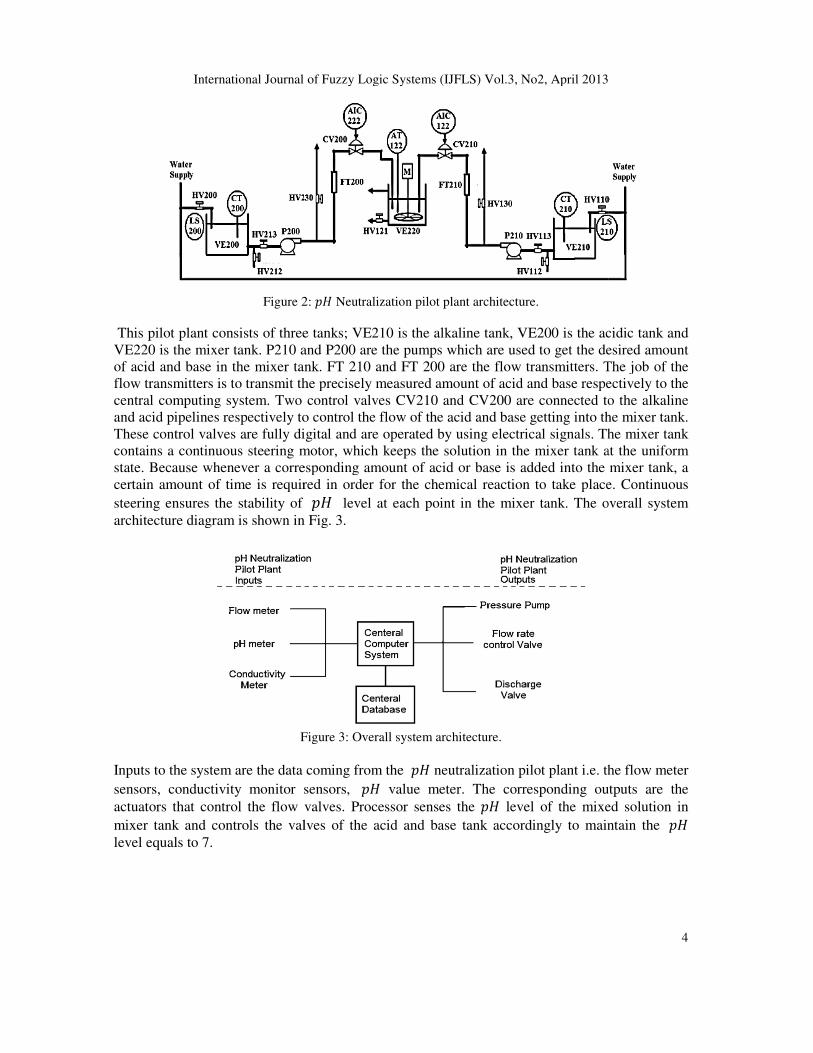
The architecture diagram of �� neutralization pilot plant is shown in Fig 2. This plant is
assembled by using the state of the art industrial instruments and measuring systems.
International Journal of Fuzzy Logic Systems (IJFLS) Vol.3, No2, April 2013
Figure 2
This pilot plant consists of three tanks; VE210 is the alkaline tank, VE200 is the acidic tank and
VE220 is the mixer tank. P210 and P200 are the pumps which are used to get the desired amount
of acid and base in the mixer tank. FT 210 and FT 200 are the
flow transmitters is to transmit the precisely measured amount of acid and base respectively to the
central computing system. Two control valves CV210 and CV200 are
and acid pipelines respectively to control the flow of the acid and base getting into the mixer tank.
These control valves are fully digital and are operated by using electrical signals. The mixer tank
contains a continuous steering motor, which keeps the solution in the mixer tank at t
state. Because whenever a corresponding amount of acid or base is added into the mixer tank, a
certain amount of time is required in order for the chemical reaction to take place. Continuous
steering ensures the stability of
architecture diagram is shown in Fig. 3.
Figure
Inputs to the system are the data coming from the
sensors, conductivity monitor sensors,
actuators that control the flow valves. Processor senses the
mixer tank and controls the valves of the acid and base tank accordingly to maintain the
level equals to 7.
International Journal of Fuzzy Logic Systems (IJFLS) Vol.3, No2, April 2013
2: �� Neutralization pilot plant architecture.
This pilot plant consists of three tanks; VE210 is the alkaline tank, VE200 is the acidic tank and
VE220 is the mixer tank. P210 and P200 are the pumps which are used to get the desired amount
of acid and base in the mixer tank. FT 210 and FT 200 are the flow transmitters. The job of the
flow transmitters is to transmit the precisely measured amount of acid and base respectively to the
central computing system. Two control valves CV210 and CV200 are connected to the alkaline
to control the flow of the acid and base getting into the mixer tank.
These control valves are fully digital and are operated by using electrical signals. The mixer tank
contains a continuous steering motor, which keeps the solution in the mixer tank at t
state. Because whenever a corresponding amount of acid or base is added into the mixer tank, a
certain amount of time is required in order for the chemical reaction to take place. Continuous
steering ensures the stability of �� level at each point in the mixer tank. The overall system
architecture diagram is shown in Fig. 3.
Figure 3: Overall system architecture.
Inputs to the system are the data coming from the �� neutralization pilot plant i.e. the flow meter
sensors, conductivity monitor sensors, �� value meter. The corresponding outputs are the
actuators that control the flow valves. Processor senses the �� level of the mixed solution in
tank and controls the valves of the acid and base tank accordingly to maintain the
4
This pilot plant consists of three tanks; VE210 is the alkaline tank, VE200 is the acidic tank and
VE220 is the mixer tank. P210 and P200 are the pumps which are used to get the desired amount
flow transmitters. The job of the
flow transmitters is to transmit the precisely measured amount of acid and base respectively to the
connected to the alkaline
to control the flow of the acid and base getting into the mixer tank.
These control valves are fully digital and are operated by using electrical signals. The mixer tank
contains a continuous steering motor, which keeps the solution in the mixer tank at the uniform
state. Because whenever a corresponding amount of acid or base is added into the mixer tank, a
certain amount of time is required in order for the chemical reaction to take place. Continuous
level at each point in the mixer tank. The overall system
neutralization pilot plant i.e. the flow meter
value meter. The corresponding outputs are the
level of the mixed solution in
tank and controls the valves of the acid and base tank accordingly to maintain the ��
International Journal of Fuzzy Logic Systems (IJFLS) Vol.3, No2, April 2013
5
4. MATHEMATICAL MODELLING OF �� NEUTRALIZATION PILOT PLANT
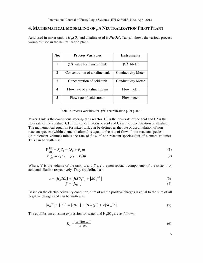
Acid used in mixer tank is ��� and alkaline used is� �. Table.1 shows the various process
variables used in the neutralization plant.
No: Process Variables Instruments
1 �� value form mixer tank �� Meter
2 Concentration of alkaline tank Conductivity Meter
3 Concentration of acid tank Conductivity Meter
4 Flow rate of alkaline stream Flow meter
5 Flow rate of acid stream Flow meter
Table 1: Process variables for �� neutralization pilot plant.
Mixer Tank is the continuous steering tank reactor. F1 is the flow rate of the acid and F2 is the
flow rate of the alkaline. C1 is the concentration of acid and C2 is the concentration of alkaline.
The mathematical equation for mixer tank can be defined as the rate of accumulation of non-
reactant species (within element volume) is equal to the rate of flow of non-reactant species
(into element volume) minus the rate of flow of non-reactant species (out of element volume).
This can be written as:
� ����
= ���� − ��� + ���� (1)
� ����
= ���� − ��� + ���� (2)
Where, V is the volume of the tank. � and � are the non-reactant components of the system for
acid and alkaline respectively. They are defined as:
� = ����� + ����� + �
��! (3)
� = ��"#� (4)
Based on the electro-neutrality condition, sum of all the positive charges is equal to the sum of all
negative charges and can be written as:
��"#� + ��#� = ���� + ���
�� + 2����� (5)
The equilibrium constant expression for water and H�SO� are as follows:
'� =�()��(*+,
-�
(.*+, (6)

International Journal of Fuzzy Logic Systems (IJFLS) Vol.3, No2, April 2013
6
'� =�()� *+,
-.!(*+,
- (7)
'/ = ��#����� (8)
'/ is the constant ionic product of water and is equal to 1.0310��. '� and '� are the two acid
dissociation constants for sulphuric acid with'� = 1.03104 and '� = 1.2310��. �� value of
the solution can be calculated by using the following equation:
5� = − log�9��#� (9)
Equation 5 can be solved for the value of Hydrogen ions H+ by using (6, 7, 8, and 9) and can be
written as:
��#�� + ���#�4 + ���#�� + 4��#�� + � (10)
� = '� + �
� = �'� + '�'� − '/ − '��
4 = �'�'� − '�'/ − 2'�'��
� = −'�'�'/
Equation 10 is the Physico-chemical �� neutralization equation for the mixer tank. The block
diagram of the resulting plant is shown in the Fig. 4.
Figure 4: Mathematical model of �� neutralization pilot plant.
Fig. 5 shows the dynamic response of the system which is clearly a non-linear system. �� value
starts from 3. The variation of �� value from 3-4 is low and from 4-6 variation is very high.
However, from �� values 6-8 the slope is quite linear and the variation is moderate. From ��
values 8-10, variation is again higher and finally from �� values 10-12 variation is low.

International Journal of Fuzzy Logic Systems (IJFLS) Vol.3, No2, April 2013
Figure 5: Dynamic response of
5. PROPORTIONAL INTEGRAL DERIVATIVE
DESIGN
The characteristics curves for flow rates of acid and alkaline valves are shown in
evident that flow control for up scaling (opening of valve) and down scaling (closing of valve) is
not the same. The error varies from 2% to 6%. PID controller is designed and tuned to capture
these variations [3].
Figure
Firstly, the proportional gain is set to a minimum value and the other parameters integral and
derivative terms are set to give zero action. The proportional gain is then gradually increased
oscillations start to appear in the measured closed
so that the oscillations maintain constant amplitude. The value of gain that is used to achieve this
condition is termed as ultimate proportional gai
on Table 2 proportional gain Kp = 10.8, integral gain Ki = 0.65 and derivative gain Kd = 44.5.
International Journal of Fuzzy Logic Systems (IJFLS) Vol.3, No2, April 2013
: Dynamic response of �� neutralization pilot plant.
NTEGRAL DERIVATIVE (PID) FLOW-RATE
The characteristics curves for flow rates of acid and alkaline valves are shown in
evident that flow control for up scaling (opening of valve) and down scaling (closing of valve) is
not the same. The error varies from 2% to 6%. PID controller is designed and tuned to capture
Figure 6: Flow-rates of acid and base streams.
Firstly, the proportional gain is set to a minimum value and the other parameters integral and
derivative terms are set to give zero action. The proportional gain is then gradually increased
oscillations start to appear in the measured closed-loop system response. The gain is then adjusted
so that the oscillations maintain constant amplitude. The value of gain that is used to achieve this
condition is termed as ultimate proportional gain with value (G=18) at the period (P=33). Based
on Table 2 proportional gain Kp = 10.8, integral gain Ki = 0.65 and derivative gain Kd = 44.5.
7
RATE CONTROL
The characteristics curves for flow rates of acid and alkaline valves are shown in Fig. 6. It is
evident that flow control for up scaling (opening of valve) and down scaling (closing of valve) is
not the same. The error varies from 2% to 6%. PID controller is designed and tuned to capture
Firstly, the proportional gain is set to a minimum value and the other parameters integral and
derivative terms are set to give zero action. The proportional gain is then gradually increased until
loop system response. The gain is then adjusted
so that the oscillations maintain constant amplitude. The value of gain that is used to achieve this
n with value (G=18) at the period (P=33). Based
on Table 2 proportional gain Kp = 10.8, integral gain Ki = 0.65 and derivative gain Kd = 44.5.

International Journal of Fuzzy Logic Systems (IJFLS) Vol.3, No2, April 2013
8
Type of Controller P PI PID
Proportional Kp 0.5 G 0.45G 0.6G
Integral Ki - 1.2Kp/P 2Kp/P
Differential Kd - - KpP/8
Table 2: Ziegler-Nichlos tuning formula for a closed loop system.
6. FUZZY LOGIC CONTROLLER DESIGN Fuzzy logic controller mainly consists of three parts: (i) Fuzzification: process of converting
system inputs (process variables) into grades of membership for linguistic of fuzzy sets, (ii)
Fuzzy interference: mapping input space to output space using membership functions, logic
operations and if-then rule statements and (iii) Defuzzification: process of producing quantifiable
results (control valve inputs for PID controller) in the light of given fuzzy sets and membership
degree. Overall performance of the fuzzy logic controller depends on the selection of the
membership function of input and output sets.
The set point of the desired �� value is entered manually while other process control variables
are controlled automatically based on the information (feedback) coming from the plant output.
The job of the fuzzy logic controller is to maintain the corresponding �� value while
manipulating the process control variables. When the current �� value is less than the desired
value, Fuzzy logic controller sets a new point for the PID valve flow rate controller. The new
value of current set point depends upon the difference between the current �� value of the plant
reactor and the desired �� value. The overall diagram of the system is shown in the Fig. 7.
Figure 7: Logical diagram of fuzzy logic and PID controller.
Table 3 shows the membership function description and the parameters for fuzzy logic input set.
The mid condition is positioned between -1 and 1 to ensure the smoothness of the desired ��
value and to make certain that the zero offset for the steady state is achievable. The overall
performance of the system is determined by the input and output sets membership functions.

International Journal of Fuzzy Logic Systems (IJFLS) Vol.3, No2, April 2013
9
.
Symbols Descriptions Type Parameters
NXL Negative Extra Large Trapezoid -5.0 -5.0 -4.0 -2.0
NL Negative Large Triangle -3.0 -2.0 -1.0
NM Negative Medium Triangle -2.0 -1.25 -0.5
NS Negative Small Triangle -1.0 -0.5 0
Z Zero Triangle -0.5 0 0.5
PS Positive Small Triangle 0 0.5 1.0
PM Positive Medium Triangle 0.5 1.25 2.0
PL Positive Large Triangle 1.0 2.0 3.0
PXL Positive Extra Large Trapezoid 2.0 4.0 5.0 5.0
Table 3: Membership function description and parameters for input set
The entire range is divided into nine levels with the value ranging from -5.0 to 5.0. Fig. 8 further
demonstrates the functionality of the input sets of fuzzy logic controller.
Figure 8: Demonstration of membership function of input set.
Fig. 9 shows the membership functions for the output set of Fuzzy logic controller. Output set is
also divided into nine levels. The output set in this case determines the output for the PID
controller (whether to increase the �� value by increasing the flow-rate of acid or to decrease
the �� value by decreasing the flow-rate of base and vice versa) and to provide a reasonable
time response.

International Journal of Fuzzy Logic Systems (IJFLS) Vol.3, No2, April 2013
10
Table 4, shows the membership function description and parameters for output set. The middle
range is set from -20 to 20, so that the variation in mid-condition remains minute.
Symbols Descriptions Type Parameters
ONXL Negative Extra Large Trapezoid -100 -100 -60 -45
ONL Negative Large Triangle -50 -40 -30
ONM Negative Medium Triangle -35 -25 -15
ONS Negative Small Triangle -20 -10 0
OZ Zero Triangle -0.5 0 0.5
OPS Positive Small Triangle 0 10 20
OPM Positive Medium Triangle 15 25 35
OPL Positive Large Triangle 30 40 50
OPXL Positive Extra Large Trapezoid 45 60 100 100
Table 4: Membership function description and parameters for output set.
Table 5 defines the relationship between the input set and output set parameters of the fuzzy logic
controller. This is one-to-one function for every input set parameter there is a corresponding
output set variable.
No: Statement
Error in
:;
Value
Statement
Manipulated
variables for
PID controller
1 IF NXL THEN ONXL
2 IF NL THEN ONL
3 IF NM THEN ONM
4 IF NS THEN ONS
5 IF Z THEN OZ
6 IF PS THEN OPS
7 IF PM THEN OPM
8 IF PL THEN OPL
9 IF PXL THEN OPXL
Table 5: If-then rules statement description of membership function and parameters for input and output
sets.

International Journal of Fuzzy Logic Systems (IJFLS) Vol.3, No2, April 2013
7. EXPERIMENTS First experiment is carried out to investigate the overall performance of the hybrid fuzzy logic
and PID controller with the introduction of a static set point (
0.052M of H2SO4 is mixed with 0.052M of NaOH. These are the typical values for this kind of
system. Two step changes are made, first at the
This experiment is useful in determining the rise time (how long will it take for the output to
follow the desired input) and overall response time of the system. Second experiment is carried
out to investigate the robustness (to determine whether the output of the system is able to track
the input or not) of hybrid Fuzzy logic and PID controller. In this experiment, different set points
are introduced at different time steps in the form of a sq
set to 1.5 and period is configured to 600 sec. The random range of values changes from
to �� = 10. The initial �� vale is set to 7. The concentration v
0.051M and 0.0489M respectively. Third experiment is performed to compare the performance of
Hybrid Fuzzy Logic and PID controller against Fuzzy Logic controller. For this experiment,
value is varied from 6 to 10 at the regular intervals and the performance of both controllers is
observed.
8. RESULTS
Fig. 10, show the results of the first experiment. Initially
sec, the input of the system cha
sec, output reaches to �� = 10. However, the output is delayed because the flow rate of PID
controller depends on the mechanical flow valves of acid and base streams. At ti
the input drops to �� = 7 but output
to �� = 7 at 660 sec. Rise and fall time delays of the system are different because the control
valve have different rise time and fall time.
Figure 9: Experiment
Fig. 11 shows the result of the second experiment. Output of the system follows the input square
wave which shows the robustness of the controller. When input
output follows the input but with the minute delay. This delayed is because the
require certain amount of time to maintain the desired flow rate.
International Journal of Fuzzy Logic Systems (IJFLS) Vol.3, No2, April 2013
First experiment is carried out to investigate the overall performance of the hybrid fuzzy logic
controller with the introduction of a static set point (�� value = 7). For this experiment,
0.052M of H2SO4 is mixed with 0.052M of NaOH. These are the typical values for this kind of
system. Two step changes are made, first at the �� value of 7 and second at the ��This experiment is useful in determining the rise time (how long will it take for the output to
follow the desired input) and overall response time of the system. Second experiment is carried
ut to investigate the robustness (to determine whether the output of the system is able to track
the input or not) of hybrid Fuzzy logic and PID controller. In this experiment, different set points
are introduced at different time steps in the form of a square wave. The amplitude of the wave is
set to 1.5 and period is configured to 600 sec. The random range of values changes from
vale is set to 7. The concentration values for acid and base are set to
0.051M and 0.0489M respectively. Third experiment is performed to compare the performance of
Hybrid Fuzzy Logic and PID controller against Fuzzy Logic controller. For this experiment,
from 6 to 10 at the regular intervals and the performance of both controllers is
Fig. 10, show the results of the first experiment. Initially �� value is set to 7. At time step 300
sec, the input of the system changes to �� = 10. Output follows the input and at time step 380
= 10. However, the output is delayed because the flow rate of PID
controller depends on the mechanical flow valves of acid and base streams. At time step 600 sec,
= 7 but output �� value starts to drop down at 610 sec and settles down
= 7 at 660 sec. Rise and fall time delays of the system are different because the control
valve have different rise time and fall time.
: Experiment-1, performance of hybrid controller.
second experiment. Output of the system follows the input square
wave which shows the robustness of the controller. When input �� value varies from 7 to 10,
output follows the input but with the minute delay. This delayed is because the control valves
require certain amount of time to maintain the desired flow rate.
11
First experiment is carried out to investigate the overall performance of the hybrid fuzzy logic
value = 7). For this experiment,
0.052M of H2SO4 is mixed with 0.052M of NaOH. These are the typical values for this kind of
�� value of 10.
This experiment is useful in determining the rise time (how long will it take for the output to
follow the desired input) and overall response time of the system. Second experiment is carried
ut to investigate the robustness (to determine whether the output of the system is able to track
the input or not) of hybrid Fuzzy logic and PID controller. In this experiment, different set points
uare wave. The amplitude of the wave is
set to 1.5 and period is configured to 600 sec. The random range of values changes from �� = 6
alues for acid and base are set to
0.051M and 0.0489M respectively. Third experiment is performed to compare the performance of
Hybrid Fuzzy Logic and PID controller against Fuzzy Logic controller. For this experiment, ��
from 6 to 10 at the regular intervals and the performance of both controllers is
value is set to 7. At time step 300
10. Output follows the input and at time step 380
= 10. However, the output is delayed because the flow rate of PID
me step 600 sec,
value starts to drop down at 610 sec and settles down
= 7 at 660 sec. Rise and fall time delays of the system are different because the control
second experiment. Output of the system follows the input square
value varies from 7 to 10,
control valves

International Journal of Fuzzy Logic Systems (IJFLS) Vol.3, No2, April 2013
Figure 10: Experiment
Fig. 12, Shows the result of third experiment. It can be seen that from time intervals
seconds, hybrid controller is more efficient in tracking the input (set points) than Fuzzy Logic
controller. Also from time interval 500
logic controller.
Figure 11: Experiment-3, comparison of Fuzzy Logic controller against Hybrid Fuzzy Logic and PID
9. CONCLUSION AND FUTURE
This paper presents a hybrid control (PID and fuzzy logic controller) for
plant. It covers the entire operating range and is more robust against the uncertainty
variation). It is noticed that proposed hybrid controller is more stable as compared to the Fuzzy
Logic controller. Process modelling approach adopted in this paper is
chemical principles and fundamental laws. A conventional mathematical modelling process is
incorporated. Practical tests are carried out on actual system to estimate manipulating variables
which were not known before the experiments.
International Journal of Fuzzy Logic Systems (IJFLS) Vol.3, No2, April 2013
: Experiment-2 robustness of hybrid controller.
Fig. 12, Shows the result of third experiment. It can be seen that from time intervals
seconds, hybrid controller is more efficient in tracking the input (set points) than Fuzzy Logic
controller. Also from time interval 500-1250 seconds, Hybrid controller is more stable than fuzzy
3, comparison of Fuzzy Logic controller against Hybrid Fuzzy Logic and PID
controller.
UTURE CONSIDERATIONS
This paper presents a hybrid control (PID and fuzzy logic controller) for �� neutralization pilot
covers the entire operating range and is more robust against the uncertainty
variation). It is noticed that proposed hybrid controller is more stable as compared to the Fuzzy
Logic controller. Process modelling approach adopted in this paper is based on the Physico
chemical principles and fundamental laws. A conventional mathematical modelling process is
incorporated. Practical tests are carried out on actual system to estimate manipulating variables
which were not known before the experiments. The design methodology (deriving dynamic non
12
Fig. 12, Shows the result of third experiment. It can be seen that from time intervals 1250-2000
seconds, hybrid controller is more efficient in tracking the input (set points) than Fuzzy Logic
1250 seconds, Hybrid controller is more stable than fuzzy
3, comparison of Fuzzy Logic controller against Hybrid Fuzzy Logic and PID
neutralization pilot
covers the entire operating range and is more robust against the uncertainty �� value
variation). It is noticed that proposed hybrid controller is more stable as compared to the Fuzzy
based on the Physico-
chemical principles and fundamental laws. A conventional mathematical modelling process is
incorporated. Practical tests are carried out on actual system to estimate manipulating variables
The design methodology (deriving dynamic non-

International Journal of Fuzzy Logic Systems (IJFLS) Vol.3, No2, April 2013
13
linear equation) presented in this paper is generally applicable to a �� neutralization plant, based
on continuous steering tank reactor. The robustness of the Hybrid controller depends upon the
process variables i.e. Acid/Base Flow rate control valve, �� value meter, flow transmitter and
concentration monitoring sensors as these instruments appear as manipulating variables during
controller design and implementation.
In this paper, PID controller is used to control the flow rate of both acid and alkaline streams and
a Fuzzy logic controller is used to control the �� value. However in future, an adaptive neural
network based controller can be used to achieve the same objective. Overall response of the
system in terms of rise and fall time heavily depends on the instruments used to assemble ��
neutralization plant. So a more predictable �� process model can be designed by using more
accurate instruments.
10. REFERENCES
[1] Butler, J. N., Ionic Equilibrium : A Mathematical Approach Addison-Wesley Publishing, Inc.,
London.1964.
[2] Christian, G. D. , "Acid-Base Equilibria," in Analytical Chemistry, Sixth edn, John Wiley & Sons,
Inc., United States of America, pp. 214-260. 2004.
[3] R. Ibrahim, “Practical modeling and control implementation studies on a ph neutalization plot
plant”, Department of Electronics and Electrical Engineering,mFaculty of Engineering,,
University of Glasgow, 2008.
[4] Alvarez, H., Londono, C., de Sciascio, F., & Carelli, R., "PH neutralization process as a
benchmark for testing nonlinear controllers", Industrial & Engineering Chemistry Research, vol.
40, no. 11, pp. 2467-2473, 2001.
[5] Bar-Eli, K. & Noyes, R. M., "A model for imperfect mixing in a CSTR", The Journal of Chemical
Physics, vol. 85, no. 6, pp. 3251-3257, 1986.
[6] McAvoy, T. J., Hsu, E., & Lowenthals, S., "Dynamics of pH in controlled stirred tank reactor",
Ind Eng Chem Process Des Develop, vol. 11, no. 1, pp. 68-78, 1972.
[7] Bates, R. G., Determination of pH: Theory and Practice, 2 edn, John Wiley & Sons, Inc, New
York, 1973.
[8] Gustafsson, T. K., "Calculation of the pH value of a mixture solutions—an illustration of the use
of chemical reaction invariants", Chemical Engineering Science, vol. 37, no. 9, pp. 1419-1421,
1982.
[9] Gustafsson, T. K. & Waller, K. V., "Dynamic modeling and reaction invariant control of pH",
Chemical Engineering Science, vol. 38, no. 3, pp. 389-398., 1983.
[10] Jutila, P., "An application of adaptive pH-control algorithms based on physicochemical in a
chemical waste-water treatment plant", International Journal of Control, vol. 38, no. 3, pp. 639-
655.1983.
[11] Gustafsson, T. K. & Waller, K. V., "Nonlinear and adaptive control of pH", Industrial &
Engineering Chemistry Research, vol. 31, no. 12, pp. 2681-2693, 1992.
[12] Henson, M. A. & Seborg, D. E., "Adaptive nonlinear control of a pH neutralization process",
Control Systems Technology, IEEE Transactions on, vol. 2, no. 3, pp. 169-182, 1994.
[13] Bohn, C. & Atherton, D. P., "SIMULINK package for comparative studies of PID anti- windup
strategies", Proceedings of the IEEE/IFAC Joint Symposium on Computer-Aided pp. 447-452,
1994.
[14] Gustafsson, T. K. & Waller, K. V., "Dynamic modelling and reaction invariant control of pH",
Chemical Engineering Science, vol. 38, no. 3, pp. 389-398, 1983.
[15] Gustafsson, T. K., Skrifvars, B. O., Sandstroem, K. V., & Waller, K. V. "Modeling of pH for
Control", Industrial & Engineering Chemistry Research, vol. 34, no. 3, pp. 820-827, 1995.
International Journal of Fuzzy Logic Systems (IJFLS) Vol.3, No2, April 2013
14
[16] Jutila, P. & Orava, J. P., "Control and Estimation Algorithms for Physico- Chemical Models of
pH-Processes in Stirred Tank Reactors", International Journal of Systems Science,vol.12, no.7,
pp.855-875, 1981.
[17] Jutila, P., "An application of adaptive pH-control algorithms based on physicochemical in a
chemical waste-water treatment plant", International Journal of Control, vol. 38, no. 3, pp. 639-
655, 1983.
[18] Jutila, P. & Visala, A., "Pilot plant testing of an adaptive pH-control algorithm based on physico-
chemical modelling", Mathematics and Computers in Simulation, vol. 26, no. 6, pp. 523-533,
1984.
[19] Gustafsson, T. K. & Waller, K. V., "Nonlinear and adaptive control of pH", Industrial &
Engineering Chemistry Research, vol. 31, no. 12, pp. 2681-2693, 1992.
[20] Bohn, C. & Atherton, D. P., "Analysis package comparing PID anti-windup strategies", IEEE
Control Systems Magazine, vol. 15, no. 2, pp. 34-40, 1995.
[21] Wright, R. A., Smith, B. E., & Kravaris, C., "On-Line identification and nonlinear control of pH
processes", Industrial and Engineering Chemistry Research, vol. 37, no. 6, pp. 2446-2461, 1998.
[22] Wright, R. A. & Kravaris, C., "On- line identification and nonlinear control of an industrial pH
process", Journal of Process Control, vol. 11, no. 4, pp. 361-374, 2001.
[23] Sung, S. W., Lee, I. B., & Yang, D. R., "pH control using an identification reactor", Industrial and
Engineering Chemistry Research, vol. 34, no. 7, pp. 2418- 2426, 1995.
[24] Yoon, S. S., Yoon, T. W., Yang, D. R., & Kang, T. S., "Indirect adaptive nonlinear control of a pH
process", Computers and Chemical Engineering, vol. 26, no. 9, pp. 1223-1230, 2002.
[25] Yoon, S. S., Yoon, T. W., Yang, D. R., & Kang, T. S., "Indirect adaptive nonlinear control of a pH
process", Computers and Chemical Engineering, vol. 26, no. 9, pp. 1223-1230, 2002.
[26] George, J. K. & Yuan B, Fuzzy Sets and Fuzzy Logic : Theory and Applications Prentice Hall,
PTR, New Jersey.1995.
[27] Kelkar, B. & Postlethwaite, B. 1994, "Fuzzy- model based pH control", IEEE International
Conference on Fuzzy Systems, vol. 1, pp. 661-666.1994.
[28] Karr, C. L. & Gentry, E. J, "Fuzzy control of pH using genetic algorithms", IEEE Transactions on
Fuzzy Systems, vol. 1, no. 1, pp. 46-53.1993.
[29] Karr, C. L., "Design of a cart-pole balancing fuzzy logic controller using a genetic algorithm",
Proceeding of The International Society for Optical Engineering, vol. 1468, pp. 26-36.1991.
[30] Gong, M. & Murray-Smith, D. J., "A practical exercise in simulation model validation",
Mathematical and Computer Modelling of Dynamical Systems, vol. 4, no. 1, pp. 100-117.1998.
[31] Murray-Smith, D. J, "Issues of Model Accuracy and External Validation for Control System
Design", Acta Polytechnica, vol. 40, no. 3.2000.
[32] Murray-Smith, D. J., "Simulation Model Quality Issues In Engineering: A Review", Proceedings
5th Symposium on Mathematical Modelling, MATHMOD Vienna, Austria, 2006.
[33] Harvey, D., Morden Analytical Chemistry The McGraw-Hill Companies, Inc., Singapore.2000.
[34] Jamshidi, M., Ross, T. J., & Vadiee, N., Fuzzy Logic and Control: Software and Hardware
Applications Prentice Hall, Inc., New Jersey.1993.
[35] S. Vaishnav, Z. Khan. Design and Performance of PID and Fuzzy Logic Controller with Smaller
Rule Set for Higher Order System. International Conference on Modeling, Simulation and
Control, San Francisco, USA. Pages 24-26: 855–858, 2007.
[36] B. Hamed and A. El Khateb, "Hybrid Takagi-Sugeno fuzzy FED PID control of nonlinear
systems," Intelligent Systems and Automation, vol. 1019, pp. 99-102, 2008.