
Hybrid Conveyor Chains – Calculation, Design and Manufacturing
13
Hybrid Conveyor Chains – Calculation, Design and Manufacturing Clemens Rohne 1 , Michael Schreiter 2 , Jens Sumpf 1 , Klaus Nendel 1 , Lothar Kroll 2 1 Institut für Fördertechnik und Kunststoffe, Technische Universität Chemnitz, Reichenhainer Straße 70, 09126 Chemnitz, Germany 2 Professur Strukturleichtbau und Kunststoffverarbeitung, Technische Universität Chemnitz, Reichenhainer Straße 31/33, 09126 Chemnitz, Germany First publication at: International Symposium Plastic-Slide-Chains and Tribology in Conveyor Systems: Proceedings, Vol. 3, April 2017, Chemnitz, ISBN 978-3-945479-08-7, p. 65-77 Online publication: http://nbn-resolving.de/urn:nbn:de:bsz:ch1-qucosa-231781 ABSTRACT The following paper will illustrate the development of a multiflex chain in hybrid construction. The aim of this novel chain variant is to improve the stiffness and strength in comparison to conventional plastic slide chains. A two part multiflex chain with a chain pitch of 33.5 mm and a structural width of 83 mm was used as the basis for the development of the hybrid multiflex chain. The hybrid multiflex chain is supposed to be integrated in already existing layouts of chain conveyors. The load bearing structure of the single chain links is manufactured in the metal die cast procedure while taking the constructive, production related, and operational aspects into consideration and subsequently covered in the injection molding process with plastics commonly used for multiflex chains. The evaluation of the improved stiffness and strength takes place in the course of extensive test series. KEYWORDS hybrid, conveyor chain, metal die-cast, injection molding KURZFASSUNG Hybride Förderketten – Auslegung, Konstruktion und Fertigung: In der folgenden Abhandlung wird die Entwicklung einer Multiflex-Kette in Hybridbauweise erläutert. Mit dieser neuartigen Kettenvariante soll eine Steifigkeits- und Festigkeitssteigerung gegenüber den konventionellen Kunststoffgleitketten erzielt werden. Als Ausgangsbasis für die Entwicklung der hybriden Förderkette dient eine zweiteilig ausgeführte Multiflex-Kette mit der Teilung von 33,5 mm und einer Baubreite von 83 mm. Die hybride Förderkette soll in bestehende Layouts von Kettenförderern integriert werden können. Unter Beachtung konstruktiver, fertigungs- technischer und betrieblicher Aspekte wird die lasttragende Struktur der einzelnen Kettenglieder im Metalldruckgussprozess gefertigt und anschließend mit einem, für Multiflex- Ketten üblichen Kunststoff im Spritzgießprozess ummantelt. Die Evaluierung der Steifigkeits- bzw. Festigkeitssteigerung erfolgt im Rahmen umfangreicher Versuchsreihen. SCHLAGWÖRTER Hybrid, Förderkette, Metalldruckguss, Spritzguss
Transcript of Hybrid Conveyor Chains – Calculation, Design and Manufacturing

Hybrid Conveyor Chains – Calculation, Design and Manufacturing
Clemens Rohne 1, Michael Schreiter 2, Jens Sumpf 1, Klaus Nendel 1, Lothar Kroll 2 1 Institut für Fördertechnik und Kunststoffe, Technische Universität Chemnitz, Reichenhainer Straße 70,
09126 Chemnitz, Germany 2 Professur Strukturleichtbau und Kunststoffverarbeitung, Technische Universität Chemnitz, Reichenhainer
Straße 31/33, 09126 Chemnitz, Germany
First publication at: International Symposium Plastic-Slide-Chains and Tribology in Conveyor Systems: Proceedings, Vol. 3, April 2017, Chemnitz, ISBN 978-3-945479-08-7, p. 65-77
Online publication: http://nbn-resolving.de/urn:nbn:de:bsz:ch1-qucosa-231781
ABSTRACT The following paper will illustrate the development of a multiflex chain in hybrid construction. The aim of this novel chain variant is to improve the stiffness and strength in comparison to conventional plastic slide chains. A two part multiflex chain with a chain pitch of 33.5 mm and a structural width of 83 mm was used as the basis for the development of the hybrid multiflex chain. The hybrid multiflex chain is supposed to be integrated in already existing layouts of chain conveyors. The load bearing structure of the single chain links is manufactured in the metal die cast procedure while taking the constructive, production related, and operational aspects into consideration and subsequently covered in the injection molding process with plastics commonly used for multiflex chains. The evaluation of the improved stiffness and strength takes place in the course of extensive test series.
KEYWORDS hybrid, conveyor chain, metal die-cast, injection molding
KURZFASSUNG Hybride Förderketten – Auslegung, Konstruktion und Fertigung: In der folgenden Abhandlung wird die Entwicklung einer Multiflex-Kette in Hybridbauweise erläutert. Mit dieser neuartigen Kettenvariante soll eine Steifigkeits- und Festigkeitssteigerung gegenüber den konventionellen Kunststoffgleitketten erzielt werden. Als Ausgangsbasis für die Entwicklung der hybriden Förderkette dient eine zweiteilig ausgeführte Multiflex-Kette mit der Teilung von 33,5 mm und einer Baubreite von 83 mm. Die hybride Förderkette soll in bestehende Layouts von Kettenförderern integriert werden können. Unter Beachtung konstruktiver, fertigungs-technischer und betrieblicher Aspekte wird die lasttragende Struktur der einzelnen Kettenglieder im Metalldruckgussprozess gefertigt und anschließend mit einem, für Multiflex-Ketten üblichen Kunststoff im Spritzgießprozess ummantelt. Die Evaluierung der Steifigkeits- bzw. Festigkeitssteigerung erfolgt im Rahmen umfangreicher Versuchsreihen.
SCHLAGWÖRTER Hybrid, Förderkette, Metalldruckguss, Spritzguss

C. Rohne et al. / International Symposium Plastic-Slide-Chains and Tribology in Conveyor Systems (2017) 2
1. Motivation
Multiflex chains are used in internal logistic processes, for example in the food, beverages, cosmetics, and pharmaceutical industry. They are characterized by a lubricant free operation, low maintenance, good chemical and corrosive resistance and the possibility of large scale production via the injection molding process. The time dependent strain behavior of the used plastics (e. g. POM: polyoxymethylene, PBT: polybutylene terephthalate, PA: polyamide) results in an elongation of the chain in standard load conditions during operation. This has a negative impact on the drive situation and consequently leads to an increased abrasion of the chain links and drive components. Therefore, not only the durability of the chain but also the logistic process safety is dependent on the elongation of the chain. Steel chains are also widely used in addition to plastic sliding chains. Although they demonstrate a higher stiffness and strength in comparison to plastic slide chains, their unfavorable tribological properties demand for the usage of lubricants while operating.
The development of a hybrid conveyor chain targets to combine the advantages of the plastic conveyor chains with those of the steel conveyor chains. In order to do so, the tensile force stressed core component is made of a die cast zinc alloy and the tribological stressed surface preferably of POM and manufactured in the injection molding process. To reduce the manufacturing and assembly effort of the single chain links to a minimum the merging or rather the spatial concentration of the production technologies pressure die casting and injection molding is aimed for.
2. Analysis of an Already Existing Multiflex Chain
The base for the development of a metal reinforced plastic slide chain was a multiflex chain. Its components are displayed in Figure 1. The chain links are used as traction elements, the carrier plates for the loading of goods, and the bolts and pins serve as connection and motion elements. Bolts and pins form a gimbal joint and ensure a height and side flexible movement of the chain. Within the guiding profile the chain is supported by slide rails. The material combination of carrier plates/slide rails provides lower friction coefficients and therefore a reduced energy input for the movement of the chain in the guiding profile.
The sprocket serves as the drive of the chain (displayed in Figure 2 in grey colors). The single chain links are pulled into the space between the teeth and the chain is set into a translational movement by the rotation of the sprocket. Figure 2 shows a schematic of the force progression beginning at the sprocket, leading through the bolt and pin into the chain link and finally gets transited into the following chain link.
Due to the demand of compatibility of the hybrid chain links with already existing layouts resulting in the usage of standardized components for their operation, there is only limited avail-able space of installation for the integration of a reinforcing structure into to a chain link itself. With regard to the force progression displayed in Figure 2 it is necessary to design the geometry of the metal reinforcing structure in an optimal way.

C. Rohne et al. / International Symposium Plastic-Slide-Chains and Tribology in Conveyor Systems (2017) 3
Figure 1: Parts of a multiflex chain (left), operating multiflex chain in a guiding profile (right) [1] [2]
Figure 2: Analysis of the force progression within a chain link [1]
3. Building up the Simulation
The manufacturing of the load bearing basic structure of the chain link is going to take place in a die casting process. This offers the possibility of a near net shape design of the reinforcement inlay reducing extensive post processing steps and allowing a prompt and clocked processing in the injection mold. The partial substitution of plastic with metal results in a significant increase in mass. Therefore, a compromise between the improvement in stiffness and strength and the task to add as little as possible additional mass into the chain link system is aimed for.
Figure 3: Study of different reinforcement geometries [3]

C. Rohne et al. / International Symposium Plastic-Slide-Chains and Tribology in Conveyor Systems (2017) 4
Figure 3 presents three construction variants of the reinforcement inlay. In variant 1 (V1) the geometry of the inlay follows the contour of the chain link. In variant 2 (V2) the inlay geometry deviated in the area of the tension members and follows a straight line to the feed-through holes of the bolt. Whereas in variant 3 the connection bridge between the tension members was removed in order to achieve a further reduction in mass, this means also removing the possibility of an exact positioning of the reinforcement inlay in the injection mold. [1]
A wall thickness of 1 mm was assumed for the numeric deformation analysis of the reinforcement structure. The results are displayed in Table 1. Apart from the deformation in tensile direction (X-direction) the deformation orthogonal to the tensile direction (Z-direction) was also investigated. The results show that with the reinforcement inlay made of die cast zinc the deformation of the chain link can be reduced in X-direction by 53% in variant 1, by 57% in variant 2, and in variant 3 by 55%. The deformation of the chain link in Z-direction can be reduced by 12% in variant 1, by 24% in variant 2, and by 16% in variant 3.
The findings of the design analysis resulted in a further investigation of variant 2 of the reinforcement inlay geometry in the development process and provides the starting position for the development of the die casting and injection mold. As already mentioned, the substitution of the plastic with the metal reinforcement leads due to density differences (cf. Table 2) to an increase in mass of the single chain link. At this point the compromise is needed: on the one hand, to improve the stiffness and strength (wall thickness of the reinforcement inlay as big as possible) and, on the other hand, to minimize the additionally integrated mass (wall thickness of reinforcement inlay as small as possible).
Table 1: Analysis of deformation for pre-selection of reinforcement geometries [3]
No reinforcement
Reinforcement structure V1
Reinforcement structure V2
Reinforcement structure V3
Tensile force [N] 1000 1000 1000 1000 Chain link: deformation X-direction [mm] 0,15 0,071 0,062 0,067
Chain link: deformation Z-direction [mm] 0,025 0,022 0,019 0,021
Reinforcement structure: deformation X-direction [mm] - 0,069 0,065 0,066
Reinforcement structure: deformation X-direction [mm] - 0,022 0,019 0,021
The second variant (V2) of the reinforcement inlay design was modelled with different wall thicknesses and a material model with specific properties of the die casting zinc alloy ZnAl4Cu1 (ZAMAK5) (see Table 2) and subsequently investigated with numeric calculation methods regarding their deformation behavior (cf. Table 1).
The die cast aluminum alloy AlSi10Mg provides an interesting material alternative for the reinforcing structure. It is characterized by a lower density but also by lower mechanical proper-ties. In comparison, with regard to the yield strength Rp02, tensile strength, and Young's modulus per density (so called specific stiffness/strength), is the die cast aluminum alloy equal if not even superior to the die cast zinc alloy. The disadvantages of the die cast aluminum alloy are clearly
C. Rohne et al. / International Symposium Plastic-Slide-Chains and Tribology in Conveyor Systems (2017) 5
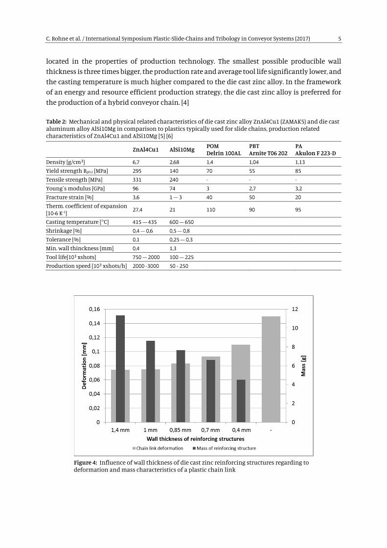
located in the properties of production technology. The smallest possible producible wall thickness is three times bigger, the production rate and average tool life significantly lower, and the casting temperature is much higher compared to the die cast zinc alloy. In the framework of an energy and resource efficient production strategy, the die cast zinc alloy is preferred for the production of a hybrid conveyor chain. [4]
Table 2: Mechanical and physical related characteristics of die cast zinc alloy ZnAl4Cu1 (ZAMAK5) and die cast aluminum alloy AlSi10Mg in comparison to plastics typically used for slide chains, production related characteristics of ZnAl4Cu1 and AlSi10Mg [5] [6]
ZnAl4Cu1 AlSi10Mg POM Delrin 100AL
PBT Arnite T06 202
PA Akulon F 223-D
Density [g/cm³] 6,7 2,68 1,4 1,04 1,13 Yield strength Rp0,2 [MPa] 295 140 70 55 85 Tensile strength [MPa] 331 240 - - - Young`s modulus [GPa] 96 74 3 2,7 3,2 Fracture strain [%] 3,6 1 – 3 40 50 20 Therm. coefficient of expansion [10-6 K-1]
27,4 21 110 90 95
Casting temperature [°C] 415 – 435 600 – 650 Shrinkage [%] 0,4 – 0,6 0,5 – 0,8 Tolerance [%] 0,1 0,25 – 0,3 Min. wall thinckness [mm] 0,4 1,3 Tool life[10³ xshots] 750 – 2000 100 – 225 Production speed [10³ xshots/h] 2000 -3000 50 - 250
Figure 4: Influence of wall thickness of die cast zinc reinforcing structures regarding to deformation and mass characteristics of a plastic chain link

C. Rohne et al. / International Symposium Plastic-Slide-Chains and Tribology in Conveyor Systems (2017) 6
The results of the wall thickness analysis are displayed in Figure 4. In the die cast zinc process a wall thickness of 0.4 mm is from the process technical related perspective the smallest feasible result. The upper limit of 1.4 mm results from the geometrical boundary conditions that are given by the chain link. The smallest deformation occurred in the model with a reinforcement wall thickness of 1.4 mm. The difference to a model with a reinforcement wall thickness of 1.0 mm is marginal. First detectable deformation was at a wall thickness of 0.85 mm and continued to occur by further reduction of wall thickness. In contrast to that is the development of inlay mass with reduced wall thickness. The wall thickness for the reinforcement inlays was set to 0.8 mm based on the results of the parameter study. Thus, the foundation for the construction and production of the die cast and injection mold was laid.
Furthermore, the exact and correct positioning of the metallic reinforcement inlay in the injection mold is of highest priority as to ensure the optimal connection of metal and plastic and the therewith optimal force progression within the chain link. In order to comply, retaining elements were integrated on the inside of the tensile members and the connecting bridge (see Figure 5). In section 4.2 of this paper, the positioning of the reinforcement inlay in the injection mold will be further enlarged on.
Figure 5: Preferred option of metallic reinforcement inlay
4. Manufacturing of the Die Cast and Injection Mold
A requirement in the manufacturing of the metal-plastic-hybrid chain links was the single step performance of the die cast and injection molding processes. This results in the advantage, especially in the injection molding process, to operate without opening the mold for the re-positioning of the reinforcement inlay. Furthermore, in a single step process the negative impact of joint defects between metal and plastics as well as plastics and plastics is reduced. This way, a single overmold of the metal reinforcement structure with plastics achieve the maximum of form closure and peak traction.

C. Rohne et al. / International Symposium Plastic-Slide-Chains and Tribology in Conveyor Systems (2017) 7
4.1. Die Casting Mold
The manufacturing of the die casting mold required the further development of the CAD model of the reinforcement inlay. Ejector pins were placed at the inlay to simplify the later demolding of the casting from the mold. The demolding ejector pins are displayed in orange, red, green, and violet in Figure 6 (left). The gate system guiding the melted metal in the cavity is colored magenta. The runner leading to the cavity is realized with a gate diameter of 9 mm². This results in a fast filling of the cavity with metal melt with low turbulence. To show the holes of the bolt and the elongated holes in the front part of the inlay, four cores were planned for the tool (see Figure 6, right). The control of the ejector pins and the core pulls happens hydraulically.
Figure 6: CAD model [7] of reinforcement structure for manufacturing of die cast mold (left), ejector half of die cast mold (right)
4.2. Injection Mold
Extensive cavity filling simulations with regard to the flow behavior of the melted plastic during the filling of the mold were performed in preparation of the manufacturing of the injection mold. The focus was on the formation of air pockets and welding lines. The parameters melt temperature, mold temperature, and inlay temperature have a relevant impact on the mold filling behavior, especially in the processing of inlay structures with complex geometry. Furthermore, the flow analysis contributes to the plastic suitable design of the component and potential errors in the component design can be discovered and prevented beforehand. The mold filling behavior for the hybrid chain link was verified with the material PBT Arnite® T06 202. The melt temperature was set to 245 °C and the mold wall temperature to 90 °C. The inlay temperature was assumed to 23 °C in the simulation model. In order to achieve a symmetric overmold of the inlay the gate was placed on the front site. The mold filling simulation determined a filling time of 1,042 s for the hybrid chain link (see Figure 7, left). Furthermore, potential locations of air pockets and welding lines could be detected during the simulation (see Figure 7, right). To prevent air pockets that could lead to burnings on the molded part due to air compression, it is necessary to include measures for better ventilation in the construction of the injection mold. [1]
Thus, to achieve a steady injection molding process the positioning and fixation of the metallic inlay in the mold cavity is of great significance. Inside the mold, internal pressures of several

C. Rohne et al. / International Symposium Plastic-Slide-Chains and Tribology in Conveyor Systems (2017) 8
hundred bar can occur and shift the inlays under the influence of the melt pressure. To prevent this disturbance impact a constructive measure for the correct positioning of the inlay has to be guaranteed. Several solution approaches regarding this problem were investigated. The in section 3 described and specifically arranged retaining elements on the inlay allow the exact positioning of the metallic reinforcement structure by being placed inside the mold cavity on a protruding rectangular core (fixed mold core) (see Figure 8). [1]
Furthermore, by closing the mold the retaining elements are clamped in between the parting plane, preventing a shift of the inlay. Thus, at this position of the inlay an overmolding is not possible. The affected part is not exposed to mechanical or tribological use and is after the assembly of the carrier plate on the chain link protectively covered. Further fixation of the inlay is achieved by hydraulic operated mold cores diving across the parting plane through the bolt holes into the inlay. [1]
Figure 7: Simulation of cavity filling with PBT Arnite® T06 202 (left), potential locations of air pockets during the processing (right) [1]
Figure 8: Fixation of the reinforcement structure within the mold cavity, CAD model (left) [1], injection mold (right)
5. Manufacturing and Experimental Investigation of Die Cast Zinc Reinforcement Structures and Hybrid Chain Links
The die cast zinc reinforcement structure was cast in a preproduction run of 1000 pieces. Figure 9 (left) shows the complete casted zinc reinforcement inlay with gate system. For further work

C. Rohne et al. / International Symposium Plastic-Slide-Chains and Tribology in Conveyor Systems (2017) 9
in the injection mold, the gate system is cut off, the inlay deburred and the surface post treated with a fully automatic barrel finishing, washing and drying procedure (see Figure 9, right).
In the following, the zinc reinforcement inlay was overmolded after a defined test design with the plastics PP (polypropylene) (see Figure 10), PBT, PA and POM
Figure 9: Cast blank with gate system (left), reinforcing structure ready for injection moulding (right)
Figure 10: Reinforcing structure overmolded with PP after injection molding process
After the production of the zinc reinforcement structures and first hybrid chain links the verification of stiffness and strength properties in quasi-static tensile tests followed. The first step was the investigation of strength and deformation properties of single zinc inlays. Reproducible results occurred at a maximum of approx. 3700 N tensile force, elongation at brake ca. 3.2% as well as a consistent failure of the inlay in the area of the tension members (see Figure 11).
Zinc inlays were tested after seven months under the same boundary conditions again. The maximal tensile force was on average 2600 N and the average elongation at brake was 4.2%. The failure area was in the front part at the elongated hole. Those two test series show the ageing of the zinc alloy. How the ageing behavior is influenced by the plastic overmold is not yet determined. Further investigations, especially the analysis if mold temperature or melt temperature have a positive or negative impact on the ageing behavior, are required. [1]

C. Rohne et al. / International Symposium Plastic-Slide-Chains and Tribology in Conveyor Systems (2017) 10
Figure 11: Force-deflection graph of new reinforcing structures (dotted lines) and aged structures (solid lines)
Figure 12: Force-deflection behavior of standard chain links (solid lines) and reinforced chain links (dotted lines)

C. Rohne et al. / International Symposium Plastic-Slide-Chains and Tribology in Conveyor Systems (2017) 11
The focus of increased tensile forces was on the material combinations PP/Zinc, PBT/Zinc, PA/Zinc, and POM/Zinc. Depending on the loading situation (slide rails, curve wheels, slope grades of up to 30°, etc.) forces between 1000 N and 2000 N act typically on the multiflex chains during operation. Thus, the force-deflection graph of this area is of great interest and receives separate attention.
Figure 12 shows force-deflection graphs of unreinforced standard chain links and zinc rein-forced hybrid chain links. Clearly visible is the reduced ability of the PP to bear tensile forces and its significantly reduced stiffness in comparison to PBT, PA, and POM. The use of zinc reinforcement increases the maximal tensile force and the stiffness, especially in the working area of 1000 N to 2000 N of multiflex chains. The force-deflection graphs of the standard chain links PBT, PA, and POM show almost identical stiffness in the area between 1000 N and 2000 N and only start to deform after tensile forces of 2500 N in a different way. [1]
The zinc reinforcement increased the stiffness most prominently in the combination with PA, followed by PBT. Zinc reinforced POM chain links show no significant increase of stiffness in the working area. With increased tensile forces, a significant difference between reinforced and unreinforced PA, PBT, and POM chain links is visible. The increase of maximal bearing tensile forces is with approx. 1800 N in POM much more distinct than with PBT (approx. 1000 N) or PA (approx. 800 N). The failure behavior of the chain links differs clearly. The standard chain links made of PP and PA show no open crack or break. The PBT chain links partially show constrictions in the area of the pin hole and in one case a clear break in the back part of the tensile members, while all POM standard chain links break brittle either at the tensile members or at the pin hole. The zinc reinforced PP chain links partially show clear failure of plastic and metal at the pin hole, but sometimes only plastic detachment or break. [1]
Nine out of ten zinc reinforced PA chain links showed no failure behavior, for example breaks or crack initiation. Only in one case did the chain link clearly break in the transition of the pin hole to the tensile members. While the PBT chain links with zinc reinforcement showed no open failure behavior, the reinforced POM chain links showed cracks and breaks at the pin hole and in the transition to the tensile members (see Figure 13). [1]
Figure 13: Hybrid chain links after quasi-static tensile testing: PP/Zinc (left), PBT/Zinc (center), POM/Zinc (right)
C. Rohne et al. / International Symposium Plastic-Slide-Chains and Tribology in Conveyor Systems (2017) 12
6. Summary and Outlook
The present paper illustrated the development of a hybrid conveyor chain based on the geometry of a multiflex chain. The idea behind the development was that a metallic reinforcement structure would transfer the majority of the tensile forces in the chain while the plastic overmold would provide optimal tribological properties between the single components of the chain and the drive and deflection units. The first step of this research project was to analyze the motion and deformation behavior of multiflex chains and to derive design approaches for the constructive implementation of the reinforcement geometry. The production is supposed to take place in a die cast process with the zinc alloy ZnAl4Cu1 (ZAMAK5). This way, the reinforcement geometry can be produced force flow oriented and in a near net shape and can subsequently be completed in an injection molding process with thermoplastics such as POM, PBT, PA to a hybrid chain link. Provided that the production technologies can be merged or spatially combined, is the result a resource and energy efficient production process that can compete with conventional production strategies. As the metallic reinforcement structure includes a significant increase in the mass of the conveyor chain system, an essential part of this investigation was the optimal geometry of the reinforcement inlay. In the second step, a complex mold system for the die cast of the reinforcement structure and the injection molding of the tribological stressed outer skin of the chain link were developed. In order to achieve the best possible connection between metal and plastic the injection mold was designed for a single-step process. The third step included the production of the zinc in-lays and their overmolding with standard chain plastics. The subsequent investigation of stiffness and deformation behavior of the hybrid chain links showed a significant increase in bearable maximum force by reduced elongation and a significant increase in the stiffness, too. Future investigations on cyclical behavior, endurance tests, and the artificial ageing of chain links are required. The deformation of single chain links will be analyzed with the help of strategically placed strain gauges in order to allow the supervision of operating states in the logistics operation and to prevent possible overload scenarios of the conveyor chains. Finally, different conveyor layouts will be tested under different load scenarios in field tests and the function of hybrid conveyor chains will be proven.
Acknowledgment
This work was performed within the Federal Cluster of Excellence EXC 1075 “MERGE Technologies for Multifunctional Lightweight Structures” and supported by the German Re-search Foundation (DFG). Financial support is gratefully acknowledged

C. Rohne et al. / International Symposium Plastic-Slide-Chains and Tribology in Conveyor Systems (2017) 13
References
[1] Rohne, C.; Schreiter, M.; Tawalbeh (geb. Thurm), M.; Sumpf, J.; Nendel, K.; Kroll, L.; Müller, E.: Prozessfusion von Medtalldruckguss-/Kunststoffspritzgieß-Technologien für Komponeten von Leichtbau-Fördersystemen. In: Kroll, Lothar (Hrsg.): Technologiefusion für multifunktionale Leichtbaustrukturen – Ressourceneffizienz durch die Schlüsseltechnologie „Leichtbau“(vorläufiger Titel). Springer Vieweg; 2017
[2] Weise, S.; Nendel, K.; Sumpf, J.; Schreiter, M.; Klärner, M.; Kausch, M.; et.al.: Optimierung von Kunststoffketten durch textile Verstärkungsstrukturen; Tagungsband zum 18. Symposium Verbundwerkstoffe und Werkstoffverbunde der Deutschen Gesellschaft für Materialkunde e.V.; Verlag TU Chemnitz; 2011
[3] Rohne, C.; Schreiter, M.; Sumpf, J.; Nendel, K.; Kroll, L.: Smart High Performance Conveyor Chain Made of Plastics. Conference proceedings 2. IMTC – International Merge Technologies Conference, Chemnitz; 2015
[4] Rohne, C.; Merkel, A.; Schreiter, M.; Sumpf, J.; Nendel, K.; Müller, E.; Kroll, L.: Hochleistungsförderkette aus Kunststoff. Tagungsband zum 10. WGTL-Fachkolloquium Logistik in Garching; 10/2014
[5] http://www.zink-druckguss.de/Produkte-und-Leistungen/Zink-im-Vergleich.asp
[6] http://www.campusplastics.com/
[7] GOEPFERT Werkzeugbau & Formenbau GmbH & Co. Teilefertigung KG


![Novel calculation method for chain conveyor systems … · Figure 3: Schematic construction of a modular belt conveyor [Ra12], [SCH08] The calculation of chain conveyor systems is](https://static.fdocuments.net/doc/165x107/5ad3c4047f8b9a48398b7add/novel-calculation-method-for-chain-conveyor-systems-3-schematic-construction.jpg)
