
HVDC Transmission Systems, 4 Commutation Failure … · etc.) in the HVDC transmission system to...
45
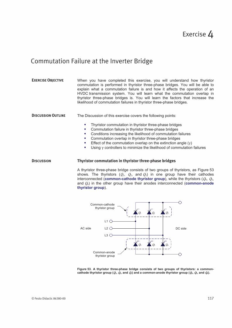
© Festo Didactic 86380-00 117 When you have completed this exercise, you will understand how thyristor commutation is performed in thyristor three-phase bridges. You will be able to explain what a commutation failure is and how it affects the operation of an HVDC transmission system. You will learn what the commutation overlap in thyristor three-phase bridges is. You will learn the factors that increase the likelihood of commutation failures in thyristor three-phase bridges. The Discussion of this exercise covers the following points: Thyristor commutation in thyristor three-phase bridges Commutation failure in thyristor three-phase bridges Conditions increasing the likelihood of commutation failures Commutation overlap in thyristor three-phase bridges Effect of the commutation overlap on the extinction angle (ɀ) Using ɀ controllers to minimize the likelihood of commutation failures Thyristor commutation in thyristor three-phase bridges A thyristor three-phase bridge consists of two groups of thyristors, as Figure 53 shows. The thyristors (ͳ, ʹ, and ͵) in one group have their cathodes interconnected (common-cathode thyristor group), while the thyristors (Ͷ, ͷ, and ) in the other group have their anodes interconnected (common-anode thyristor group). Figure 53. A thyristor three-phase bridge consists of two groups of thyristors: a common- cathode thyristor group ( ͳ , ʹ , and ͵ ) and a common-anode thyristor group ( Ͷ , ͷ , and ). Commutation Failure at the Inverter Bridge Exercise 4 EXERCISE OBJECTIVE DISCUSSION OUTLINE DISCUSSION Common-cathode thyristor group Common-anode thyristor group L1 L2 L3 ͳ ʹ ͵ Ͷ ͷ AC side DC side
Transcript of HVDC Transmission Systems, 4 Commutation Failure … · etc.) in the HVDC transmission system to...
© Festo Didactic 86380-00 117
When you have completed this exercise, you will understand how thyristor commutation is performed in thyristor three-phase bridges. You will be able to explain what a commutation failure is and how it affects the operation of an HVDC transmission system. You will learn what the commutation overlap in thyristor three-phase bridges is. You will learn the factors that increase the likelihood of commutation failures in thyristor three-phase bridges.
The Discussion of this exercise covers the following points:
Thyristor commutation in thyristor three-phase bridges
Commutation failure in thyristor three-phase bridges
Conditions increasing the likelihood of commutation failures
Commutation overlap in thyristor three-phase bridges
Effect of the commutation overlap on the extinction angle ( )
Using controllers to minimize the likelihood of commutation failures
Thyristor commutation in thyristor three-phase bridges
A thyristor three-phase bridge consists of two groups of thyristors, as Figure 53
shows. The thyristors ( , , and ) in one group have their cathodes interconnected (common-cathode thyristor group), while the thyristors ( , ,
and ) in the other group have their anodes interconnected (common-anode thyristor group).
Figure 53. A thyristor three-phase bridge consists of two groups of thyristors: a common-
cathode thyristor group ( , , and ) and a common-anode thyristor group ( , , and ).
Commutation Failure at the Inverter Bridge
Exercise 4
EXERCISE OBJECTIVE
DISCUSSION OUTLINE
DISCUSSION
Common-cathodethyristor group
Common-anode thyristor group
L1
L2
L3
AC side DC side

Exercise 4 – Commutation Failure at the Inverter Bridge Discussion
118 © Festo Didactic 86380-00
Figure 54 shows waveforms of voltages and currents in a thyristor three-phase bridge when current flows continuously at the dc side of this bridge. For every cycle of the source voltage waveform, the six thyristors in the thyristor bridge are
fired one after the other at regular intervals and in the following order: , , , , , and ; thus, a different thyristor is fired at every 60° interval. When fired,
each thyristor conducts current for an interval of 120°. The order in which the thyristors are fired causes the thyristors in the two groups (i.e., the common-cathode thyristor group and the common-anode thyristor group) to be fired alternately, (with a thyristor in each group fired every 120° interval). Consequently, at any given instant, one thyristor in the common-cathode thyristor group and one thyristor in the common-anode thyristor group are both conducting current, thereby allowing current to flow continuously through the bridge.

Exercise 4 – Commutation Failure at the Inverter Bridge Discussion
© Festo Didactic 86380-00 119
Figure 54. Waveforms of voltages and currents in a thyristor three-phase bridge when current flows continuously at the dc side of the bridge (firing angle set to 30°).
Phase angle
(°)
Phase angle (°)
Phase voltages
( )
60
90 210
150 270
330
30
90 180
150 270
330
Thyristor firing signals
Line-to-line voltages
( )
Phase angle
(°)
Phase angle
(°)
30
90 210
150 270
330
30
90 210
150 270
330
Firing angle
60 150 270210 330 30 90 150 270 210 330 90
Voltage at the dc side of the bridge
Phase angle (°)
60 150 270210 330 30 90 150 270 210 330 90
Current at the dc side of the bridge
Thyristor conduction intervals
60 150 270210 330 30 90 150 270 210 330 90
Exercise 4 – Commutation Failure at the Inverter Bridge Discussion
120 © Festo Didactic 86380-00
A thyristor has a control terminal (gate) used to turn it on. Turning the thyristor on is achieved by applying a firing signal to this terminal while the thyristor is forward biased (i.e., while the voltage at the anode is higher than the voltage at the cathode). However, the thyristor has no control mechanism to turn it off. Consequently, once the thyristor has entered into conduction, it continues to conduct even if the firing signal used to turn it on is removed. The thyristor turns off only when the current flowing through it decreases to zero and the thyristor becomes reverse biased (i.e., the voltage at the anode becomes lower than the voltage at the cathode) for a certain time. In other words, the moment at which the thyristor turns off depends on the circuit conditions only.
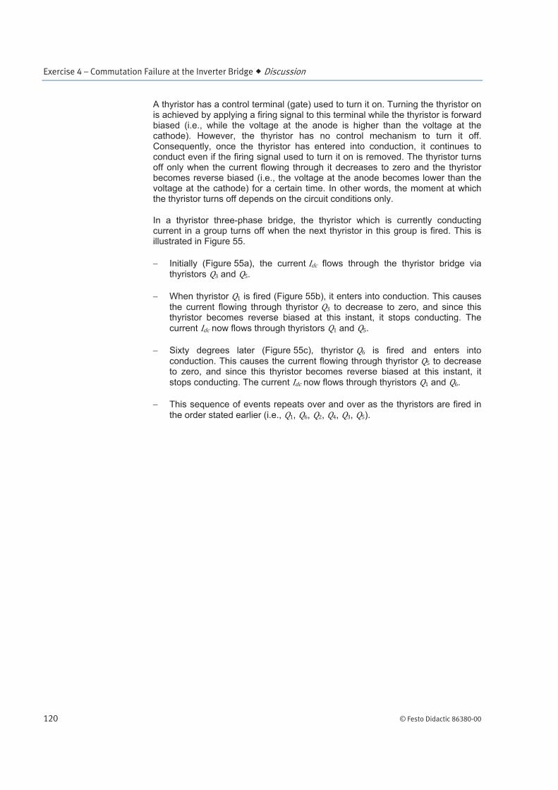
In a thyristor three-phase bridge, the thyristor which is currently conducting current in a group turns off when the next thyristor in this group is fired. This is illustrated in Figure 55.
Initially (Figure 55a), the current flows through the thyristor bridge via
thyristors and .
When thyristor is fired (Figure 55b), it enters into conduction. This causes
the current flowing through thyristor to decrease to zero, and since this thyristor becomes reverse biased at this instant, it stops conducting. The
current now flows through thyristors and .
Sixty degrees later (Figure 55c), thyristor is fired and enters into
conduction. This causes the current flowing through thyristor to decrease to zero, and since this thyristor becomes reverse biased at this instant, it
stops conducting. The current now flows through thyristors and .
This sequence of events repeats over and over as the thyristors are fired in
the order stated earlier (i.e., , , , , , ).
Exercise 4 – Commutation Failure at the Inverter Bridge Discussion
© Festo Didactic 86380-00 121
Figure 55. In a thyristor three-phase bridge, the thyristor which is currently conducting current in a group turns off when the next thyristor in this group is fired.
L1
L2
L3
L1
L2
L3
L1
L2
L3
is fired, thereby forcing
to turn off
Initial condition: current flows
through and
60° later, is fired, thereby
forcing to turn off
(a)
(b)
(c)
Exercise 4 – Commutation Failure at the Inverter Bridge Discussion
122 © Festo Didactic 86380-00
Commutation failure in thyristor three-phase bridges
Under certain circuit conditions (which will be studied later in this exercise), the thyristor that is currently conducting in a group (i.e., the outgoing thyristor) does not turn off when the next thyristor due to conduct in this group (i.e., the incoming thyristor) is fired. Consequently, the outgoing thyristor continues to conduct current , while the incoming thyristor remains off. This problem is
referred to as a commutation failure because the current fails to transfer from the outgoing thyristor to the incoming thyristor in the group.
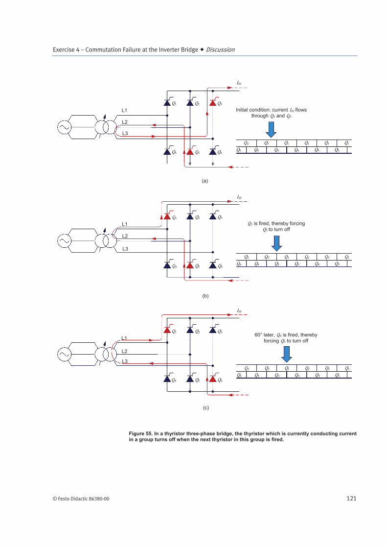
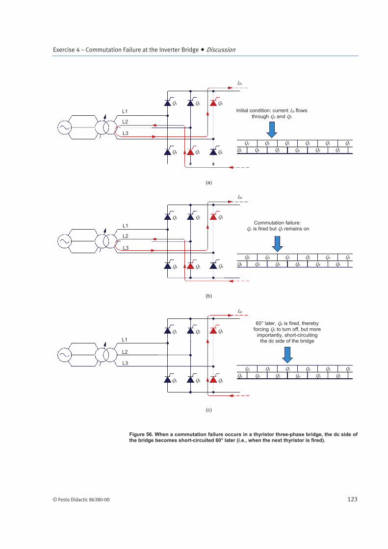
When a commutation failure occurs in a thyristor three-phase bridge, the dc side of the bridge becomes short-circuited 60° later (i.e., when the next thyristor is fired). This is illustrated in Figure 56.
Initially (Figure 56a), current flows through the thyristor bridge via thyristors and (as in the previous example).
When thyristor is fired (Figure 56b), a commutation failure occurs, and thus current continues to flow through the outgoing thyristor (i.e.,
thyristor ) and thyristor .
Sixty degrees later (Figure 56c), thyristor is fired and enters into
conduction. This causes thyristors and to be in conduction at the same time (a condition which never occurs during normal operation), thereby short-
circuiting the dc side of the bridge. Consequently, current increases rapidly and, when there is no current control circuit in the system, the overcurrent protection is very likely to trip.
Notice that commutation failures are likely to occur in thyristor bridges operating as inverters (i.e., bridges operating at firing angles higher than 90°), which will be explained later in the discussion.
Exercise 4 – Commutation Failure at the Inverter Bridge Discussion
© Festo Didactic 86380-00 123
Figure 56. When a commutation failure occurs in a thyristor three-phase bridge, the dc side of the bridge becomes short-circuited 60° later (i.e., when the next thyristor is fired).
L1
L2
L3
L1
L2
L3
L1
L2
L3
Commutation failure: is fired but remains on
60° later, is fired, thereby
forcing to turn off, but more importantly, short-circuiting
the dc side of the bridge
Initial condition: current flows
through and
(a)
(b)
(c)
Exercise 4 – Commutation Failure at the Inverter Bridge Discussion
124 © Festo Didactic 86380-00
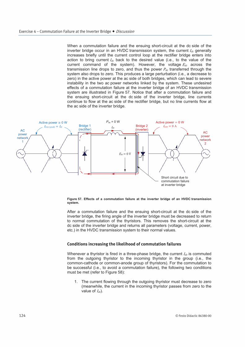
When a commutation failure and the ensuing short-circuit at the dc side of the
inverter bridge occur in an HVDC transmission system, the current generally increases briefly until the current control loop at the rectifier bridge enters into
action to bring current back to the desired value (i.e., to the value of the current command of the system). However, the voltage across the transmission line drops to zero, and thus the power transferred through the system also drops to zero. This produces a large perturbation (i.e., a decrease to zero) in the active power at the ac side of both bridges, which can lead to severe instability in the two ac power networks linked by the system. These undesired effects of a commutation failure at the inverter bridge of an HVDC transmission system are illustrated in Figure 57. Notice that after a commutation failure and the ensuing short-circuit at the dc side of the inverter bridge, line currents continue to flow at the ac side of the rectifier bridge, but no line currents flow at the ac side of the inverter bridge.
Figure 57. Effects of a commutation failure at the inverter bridge of an HVDC transmission system.
After a commutation failure and the ensuing short-circuit at the dc side of the inverter bridge, the firing angle of the inverter bridge must be decreased to return to normal commutation of the thyristors. This removes the short-circuit at the dc side of the inverter bridge and returns all parameters (voltage, current, power, etc.) in the HVDC transmission system to their normal values.
Conditions increasing the likelihood of commutation failures
Whenever a thyristor is fired in a three-phase bridge, the current is commuted from the outgoing thyristor to the incoming thyristor in the group (i.e., the common-cathode or common-anode group of thyristors). For the commutation to be successful (i.e., to avoid a commutation failure), the following two conditions must be met (refer to Figure 58):
1. The current flowing through the outgoing thyristor must decrease to zero (meanwhile, the current in the incoming thyristor passes from zero to the value of ).
AC power
network 2
Bridge 1 (rectifier)
Bridge 2 (inverter) AC
power network
1
Pdc = 0 W Active power 0 W
Active power 0 W
0 A
Short circuit due to commutation failure at inverter bridge
Exercise 4 – Commutation Failure at the Inverter Bridge Discussion
© Festo Didactic 86380-00 125
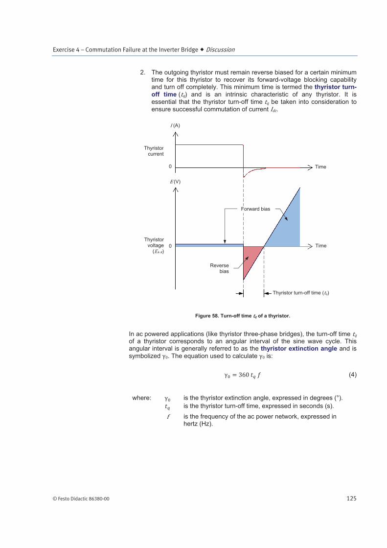
2. The outgoing thyristor must remain reverse biased for a certain minimum time for this thyristor to recover its forward-voltage blocking capability and turn off completely. This minimum time is termed the thyristor turn-off time ( ) and is an intrinsic characteristic of any thyristor. It is essential that the thyristor turn-off time be taken into consideration to
ensure successful commutation of current .
Figure 58. Turn-off time of a thyristor.
In ac powered applications (like thyristor three-phase bridges), the turn-off time of a thyristor corresponds to an angular interval of the sine wave cycle. This angular interval is generally referred to as the thyristor extinction angle and is
symbolized . The equation used to calculate is:
(4)
where: is the thyristor extinction angle, expressed in degrees (°).
is the thyristor turn-off time, expressed in seconds (s).
is the frequency of the ac power network, expressed in hertz (Hz).
(A)
Time
Thyristorcurrent
(V)
Forward bias
Time
Thyristorvoltage
( )
Thyristor turn-off time ( )
Reverse bias
0
0

Exercise 4 – Commutation Failure at the Inverter Bridge Discussion
126 © Festo Didactic 86380-00
For example, when the frequency of the ac power network is 50 Hz and the
thyristor turn-off time is 100 , the thyristor extinction angle is:
In most cases, the thyristor extinction angle never exceeds a few degrees.
When a thyristor three-phase bridge operates as a rectifier (bridge firing angle lower than 90°), commutation failures are very unlikely to occur. This is because
when the current is commuted from the outgoing thyristor to the incoming thyristor, reverse bias is applied to the outgoing thyristor for a long time interval, so that the outgoing thyristor has significant time to recover its forward-voltage blocking capability and turn off completely.
It is essential to distinguish
between the extinction angle
and the thyristor extinction
angle . The extinction an-
gle is determined by the
circuit conditions, while the
thyristor extinction angle is
an intrinsic characteristic of
any thyristor. For instance, in
thyristor three-phase bridges,
the extinction angle must be
maintained at a value higher
than the thyristor extinction
angle so that any outgoing
thyristor has enough time to
recover its forward-voltage
blocking capability and turn off
completely, thereby ensuring
successful commutation of
current .
Exercise 4 – Commutation Failure at the Inverter Bridge Discussion
© Festo Didactic 86380-00 127
For example, Figure 59 shows waveforms of voltages and currents in a thyristor three-phase bridge when the firing angle is 30°. The waveforms shown are the voltage ( ) at the common-cathode terminal of the bridge, the currents ( ,
, and ) flowing through the thyristors in the common-cathode thyristor group ( , , and ), and the voltage ( ) across thyristor (i.e., the voltage across the anode and cathode of thyristor 3). As the figure shows, the voltage is
virtually null when thyristor is conducting. When thyristor is fired, current transfers from thyristor (outgoing thyristor) to thyristor (incoming thyristor)
and voltage becomes of negative polarity, thereby applying a reverse bias to thyristor . Voltage keeps a negative polarity, and thus thyristor remains reverse biased for the next 210°. The angular interval during which thyristor
remains reverse biased is termed the extinction angle . Since the extinction angle (210° in our example) is much higher than the extinction angle (typical
value of a few degrees) of thyristor , a commutation failure is very unlikely to occur. Figure 59 also illustrates why the firing angle in a thyristor three-phase bridge cannot exceed 180°. The green shaded area in this figure shows the window of opportunity for firing thyristor and effectively transferring
(commutating) current from thyristor (outgoing thyristor) to thyristor (incoming thyristor). This window, which extends over a span of 180°,
corresponds to the angular interval during which voltage (i.e., voltage at the anode of thyristor ) is higher than voltage (i.e., voltage at the cathode of
thyristor ), which is equal to voltage since thyristor is conducting current. Firing thyristor beyond the above window of opportunity is useless (i.e., does not allow thyristor commutation) since thyristor becomes reverse
biased again due to voltage (which is still equal to voltage since thyristor is still conducting current ) becomes higher than voltage . As a
result, thyristor stays into conduction and current does not transfer to thyristor .
The angular interval between the instant when a thyristor is fired (thyristor in the example of Figure 59) and the maximum possible firing angle (180°) is referred to as the advance angle . The advance angle is a measurement of how much thyristor firing is advanced with respect to the end of the window of opportunity (i.e., the end of the green shaded area in Figure 59), which ensures thyristor firing forces current to transfer from the outgoing thyristor to the incoming thyristor. The advance angle is equal to the angular interval (180°) of the window minus the firing angle of the thyristor bridge. In equation form this is expresses as:
(5)
where: is the advance angle, expressed in degrees (°).
is the firing angle of the thyristor bridge, expressed in degrees (°).

Exercise 4 – Commutation Failure at the Inverter Bridge Discussion
128 © Festo Didactic 86380-00
Figure 59. When a thyristor three-phase bridge operates as a rectifier (bridge firing angle
lower than 90°), commutation failures are very unlikely to occur because the extinction angle is much longer than the thyristor extinction angle .
Phase angle
(°)
Phase angle (°)
Common-cathode voltage
( ) 60 120 240180 3000 300 60 120 240180 300 0
( – )
Phase angle
(°)
Phase angle (°)
Phase angle (°)
Thyristor is fired
60 120 240180 3000 300 60 120 240180 300 0
60 120 240180 3000 300 60 120 240180 300 0
60 120 240180 3000 300 60 120 240180 300 0
60 120 240180 3000 300 60 120 240180 300 0
Exercise 4 – Commutation Failure at the Inverter Bridge Discussion
© Festo Didactic 86380-00 129
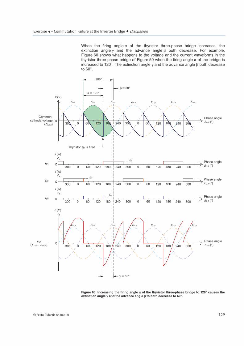
When the firing angle of the thyristor three-phase bridge increases, the extinction angle and the advance angle both decrease. For example, Figure 60 shows what happens to the voltage and the current waveforms in the thyristor three-phase bridge of Figure 59 when the firing angle of the bridge is
increased to 120°. The extinction angle and the advance angle both decrease to 60°.
Figure 60. Increasing the firing angle of the thyristor three-phase bridge to 120° causes the extinction angle and the advance angle to both decrease to 60°.
Phase angle
(°)
Phase angle (°)
Common-cathode voltage
( )
( – )
Phase angle
(°)
Phase angle (°)
Phase angle
(°)
Thyristor is fired
60 120 240180 3000 300 60 120 240 180 300 0
60 120 240180 3000 300 60 120 240 180 300 0
60 120 240180 3000 300 60 120 240 180 300 0
60 120 240180 3000 300 60 120 240 180 300 0
60 120 240180 3000 300 60 120 240 180 300 0
Exercise 4 – Commutation Failure at the Inverter Bridge Discussion
130 © Festo Didactic 86380-00
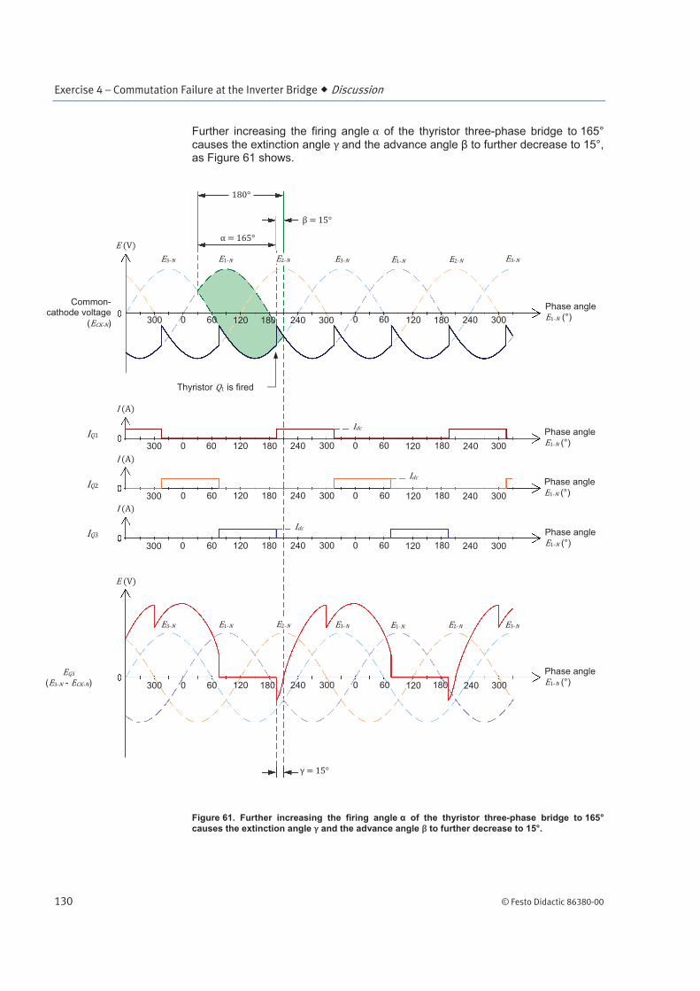
Further increasing the firing angle of the thyristor three-phase bridge to 165° causes the extinction angle and the advance angle to further decrease to 15°, as Figure 61 shows.
Figure 61. Further increasing the firing angle of the thyristor three-phase bridge to 165° causes the extinction angle and the advance angle to further decrease to 15°.
Phase angle
(°)
Phase angle (°)
Common-cathode voltage
( ) 60 120 240180 3000 300 60 120 240180 300 0
( - )
Phase angle
(°)
Phase angle
(°)
Phase angle (°)
Thyristor is fired
60 120 240180 3000 300 60 120 240180 300 0
60 120 240180 3000 300 60 120 240180 300 0
60 120 240180 3000 300 60 120 240180 300 0
60 120 240180 3000 300 60 120 240180 300 0

Exercise 4 – Commutation Failure at the Inverter Bridge Discussion
© Festo Didactic 86380-00 131
As long as the extinction angle remains significantly higher than the thyristor extinction angle , thyristor commutation should occur without failure. However,
as the firing angle of the thyristor three-phase bridge approaches the maximum value (180°), the extinction angle becomes closer to the thyristor extinction
angle , and commutation failures are more likely to occur; thus, commutation failures are more likely to occur in thyristor three-phase bridges that operate as inverters. Consequently, it is common practice to limit the maximum firing angle of thyristor three-phase bridges to less than 180° (e.g., 165°) to ensure that the
extinction angle is large enough (i.e., significantly higher than the thyristor extinction angle ) to ensure reliable thyristor commutation.
Commutation overlap in thyristor three-phase bridges
Thus far, it has been assumed that whenever a commutation occurs in a thyristor three-phase bridge, the current transfers instantaneously from the outgoing
thyristor to the incoming thyristor (see waveforms of currents , , and in the previous figures). In actuality, current does not transfer instantaneously from the outgoing thyristor to the incoming thyristor because there is generally some inductive reactance at the ac side of the bridge that limits the maximum
rate ( ) at which the line currents can vary. Inductive reactance is present in HVDC transmission systems due mainly to the leakage inductance of the multiple-tap transformer used at the ac side of each thyristor three-phase bridge.
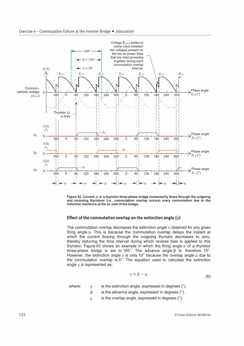
For example, Figure 62 shows the actual waveforms of the voltage at the common-cathode terminal ( ) of a thyristor three-phase bridge and the current
flowing through the common-cathode group of thyristors ( , , and ) in this bridge when the firing angle is 30°. Since current varies at a finite rate ( / ), determined mainly by the inductive reactance at the ac side of the bridge, it momentarily flows through two thyristors (i.e., through the outgoing and incoming thyristors) every commutation. This phenomenon is referred to as the commutation overlap. The angular interval corresponding to the duration of the
commutation overlap is termed the overlap angle, and is symbolized .
Due to the commutation overlap, two ac power lines are momentarily connected together, via the inductive reactance at the ac side of the bridge, every commutation. Consequently, the voltage at the common-cathode terminal of the bridge settles to some value between the voltages present on the two ac power lines that are connected together during each commutation overlap interval (this produces small notches in the waveform of the common-cathode
voltage , as shown in Figure 62).
Exercise 4 – Commutation Failure at the Inverter Bridge Discussion
132 © Festo Didactic 86380-00
Figure 62. Current in a thyristor three-phase bridge momentarily flows through the outgoing and incoming thyristors (i.e., commutation overlap occurs) every commutation due to the inductive reactance at the ac side of the bridge.
Effect of the commutation overlap on the extinction angle ( )
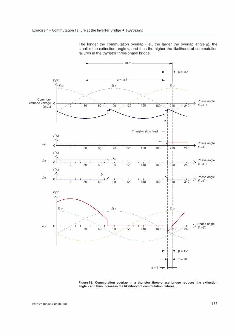
The commutation overlap decreases the extinction angle obtained for any given
firing angle . This is because the commutation overlap delays the instant at which the current flowing through the outgoing thyristor decreases to zero, thereby reducing the time interval during which reverse bias is applied to this thyristor. Figure 63 shows an example in which the firing angle of a thyristor three-phase bridge is set to 165°. The advance angle is, therefore, 15°. However, the extinction angle is only 10° because the overlap angle due to the commutation overlap is 5°. The equation used to calculate the extinction angle is represented as:
(6)
where: is the extinction angle, expressed in degrees (°).
is the advance angle, expressed in degrees (°).
is the overlap angle, expressed in degrees (°).
Phase angle
(°)
Phase angle
(°)
Common-cathode voltage
( ) 60 120 240180 3000 300 60 120 240180 300 0
Phase angle
(°)
Phase angle
(°)
Thyristor is fired
Voltage ECK-N settles to some value between
the voltages present onthe two ac power lines
that are interconnected together during each commutation overlap
interval.
60 120 240180 3000 300 60 120 240180 300 0
60 120 240180 3000 300 60 120 240180 300 0
60 120 240180 3000 300 60 120 240180 300 0
Exercise 4 – Commutation Failure at the Inverter Bridge Discussion
© Festo Didactic 86380-00 133
The longer the commutation overlap (i.e., the larger the overlap angle ), the smaller the extinction angle , and thus the higher the likelihood of commutation failures in the thyristor three-phase bridge.
Figure 63. Commutation overlap in a thyristor three-phase bridge reduces the extinction angle and thus increases the likelihood of commutation failures.
Phase angle (°)
Phase angle (°) 30 60 900 150120 210 180
Phase angle
(°)
Phase angle (°)
240
Phase angle
(°)
30 60 900 150120 210 180 240
30 60 900 150120 210 180 240
30 60 900 150120 210 180 240
Thyristor is fired
30 60 900 150120 210 180 240
Common-cathode voltage
( )
Exercise 4 – Commutation Failure at the Inverter Bridge Discussion
134 © Festo Didactic 86380-00
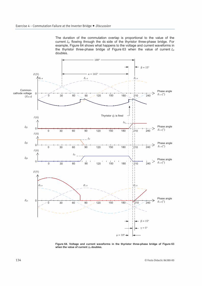
The duration of the commutation overlap is proportional to the value of the
current flowing through the dc side of the thyristor three-phase bridge. For example, Figure 64 shows what happens to the voltage and current waveforms in
the thyristor three-phase bridge of Figure 63 when the value of current doubles.
Figure 64. Voltage and current waveforms in the thyristor three-phase bridge of Figure 63 when the value of current doubles.
Phase angle
(°)
Phase angle (°)
30 60 900 150120 210180
Phase angle
(°)
Phase angle
(°)
240
Phase angle (°)
Thyristor is fired
30 60 900 150120 180 240
Common-cathode voltage
( )
30 60 900 150120 210180 240
30 60 900 150120 210180 240
30 60 900 150120 210180 240
210
Exercise 4 – Commutation Failure at the Inverter Bridge Discussion
© Festo Didactic 86380-00 135
As Figure 64 shows, the time taken by the current flowing through the outgoing
thyristor (e.g., see current in the figure) to decrease to zero doubles, and thus, the overlap angle also doubles (it passes from 5° to 10°). This, in turn, causes the extinction angle to decrease from 10° to only 5°, making the thyristor three-phase bridge much more prone to commutation failures.
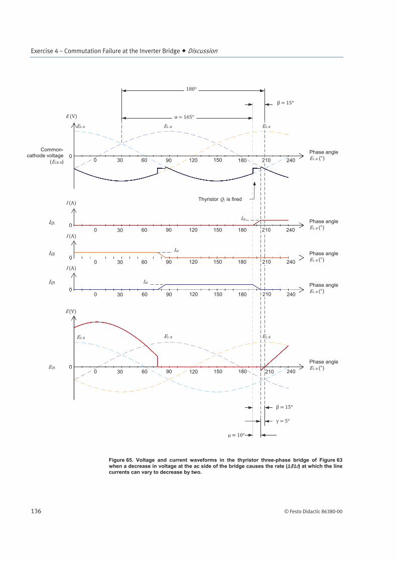
Similarly, a decrease in the voltage at the ac side of a thyristor three-phase bridge due to a fault in the ac power system connected to this bridge, significantly
decreases the rate ( / ) at which the line currents can vary (this rate being limited by the inductive reactance at the ac side of the bridge, as mentioned
earlier). Consequently, for any given value of current flowing through the dc side of a thyristor three-phase bridge, the time taken by the current flowing through the outgoing thyristor to decrease to zero increases, and thus the
overlap angle also increases.
For example, Figure 65 shows what happens to the voltage and current waveforms in the thyristor three-phase bridge of Figure 63 when a decrease in voltage at the ac side of this bridge causes the rate ( / ) at which the line currents can vary to decrease by two. Figure 65 shows that the time taken by the current flowing through the outgoing thyristor (e.g., see current in the figure) to
decrease to zero doubles, and thus the overlap angle also doubles (it passes from 5° to 10°). This, in turn, causes the extinction angle to decrease from 10° to only 5°, making the thyristor three-phase bridge much more prone to commutation failures.
Exercise 4 – Commutation Failure at the Inverter Bridge Discussion
136 © Festo Didactic 86380-00
Figure 65. Voltage and current waveforms in the thyristor three-phase bridge of Figure 63
when a decrease in voltage at the ac side of the bridge causes the rate ( / ) at which the line currents can vary to decrease by two.
Phase angle
(°)
Phase angle (°) 30 60 900 150120 210180
Phase angle
(°)
Phase angle
(°)
240
Phase angle
(°)
Thyristor is fired
30 60 900 150120 180 240
Common-cathode voltage
( )
30 60 900 150120 210180 240
30 60 900 150120 210180 240
30 60 900 150120 210180 240
210

Exercise 4 – Commutation Failure at the Inverter Bridge Discussion
© Festo Didactic 86380-00 137
Using controllers to minimize the likelihood of commutation failures
In the previous section, we saw that an increase in the value of current or a
decrease in the rate ( / ) at which the line currents can vary both cause the overlap angle to increase, which causes the extinction angle to decrease. If the extinction angle becomes lower than the thyristor extinction angle ,
commutation failures occur. To prevent this undesired situation, a controller is often used in thyristor three-phase bridges operating as inverters. A controller
continuously monitors the extinction angle by measuring the time during which reverse bias is applied to each thyristor, and automatically adjusts the firing
angle of the thyristor bridge so that the extinction angle remains higher than the thyristor extinction angle . Detailed description of the operation and use of controllers, however, is beyond the scope of this manual.
Figure 66. Converter transformers have inductance that limits the maximum rate ( ) at which line currents can vary. The above figure shows an extra-high-voltage converter transformer used in an HVDC transmission system (© Siemens AG 2012, all rights reserved).
Exercise 4 – Commutation Failure at the Inverter Bridge Procedure Outline
138 © Festo Didactic 86380-00
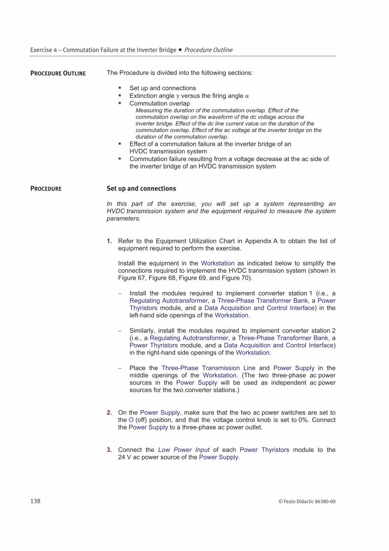
The Procedure is divided into the following sections:
Set up and connections
Extinction angle versus the firing angle
Commutation overlapMeasuring the duration of the commutation overlap. Effect of the commutation overlap on the waveform of the dc voltage across the inverter bridge. Effect of the dc line current value on the duration of the commutation overlap. Effect of the ac voltage at the inverter bridge on the duration of the commutation overlap.
Effect of a commutation failure at the inverter bridge of an HVDC transmission system
Commutation failure resulting from a voltage decrease at the ac side of the inverter bridge of an HVDC transmission system
Set up and connections
In this part of the exercise, you will set up a system representing an HVDC transmission system and the equipment required to measure the system parameters.
1. Refer to the Equipment Utilization Chart in Appendix A to obtain the list of equipment required to perform the exercise.
Install the equipment in the Workstation as indicated below to simplify the connections required to implement the HVDC transmission system (shown in Figure 67, Figure 68, Figure 69, and Figure 70).
Install the modules required to implement converter station 1 (i.e., a Regulating Autotransformer, a Three-Phase Transformer Bank, a Power Thyristors module, and a Data Acquisition and Control Interface) in the left-hand side openings of the Workstation.
Similarly, install the modules required to implement converter station 2 (i.e., a Regulating Autotransformer, a Three-Phase Transformer Bank, a Power Thyristors module, and a Data Acquisition and Control Interface) in the right-hand side openings of the Workstation.
Place the Three-Phase Transmission Line and Power Supply in the middle openings of the Workstation. (The two three-phase ac power sources in the Power Supply will be used as independent ac power sources for the two converter stations.)
2. On the Power Supply, make sure that the two ac power switches are set to the O (off) position, and that the voltage control knob is set to 0%. Connect the Power Supply to a three-phase ac power outlet.
3. Connect the Low Power Input of each Power Thyristors module to the 24 V ac power source of the Power Supply.
PROCEDURE OUTLINE
PROCEDURE

Exercise 4 – Commutation Failure at the Inverter Bridge Procedure
© Festo Didactic 86380-00 139
Connect the Power Input of each Data Acquisition and Control Interface to the 24 V ac power source of the Power Supply.
Turn the 24 V ac power source of the Power Supply on.
4. Connect the USB port of each Data Acquisition and Control Interface to USB ports of the host computer.
5. Turn the host computer on, then start the LVDAC-EMS software.
In the LVDAC-EMS Start-Up window, make sure that both Data Acquisition and Control Interfaces (DACIs) are detected (the serial number of each DACI appears in the LVDAC-EMS Start-Up window). Select the network voltage and frequency that correspond to the voltage and frequency of your local ac power network, then click the OK button to close the LVDAC-EMS Start-Up window.
6. On the Power Thyristors module in converter station 1, set switches S1 and S2 to the I (on) position. This interconnects thyristors through of this Power Thyristors module in a thyristor three-phase bridge for station 1.
On the Power Thyristors module in converter station 2, set switch S1 to the I (on) position. Set switch S2 to the O (off) position, which will allow you to connect meters in the thyristor three-phase bridge for station 2.
Connect the equipment as shown in Figure 67, Figure 68, Figure 69, and Figure 70. Before you begin connecting the equipment, record in the space below the serial numbers of the DACI modules used to control the thyristor bridges in converter stations 1 and 2.
Serial number of the DACI controlling the thyristor bridge (bridge 1) in
station 1 (left-hand station)
Serial number of the DACI controlling the thyristor bridge (bridge 2) in station 2 (right-hand station)
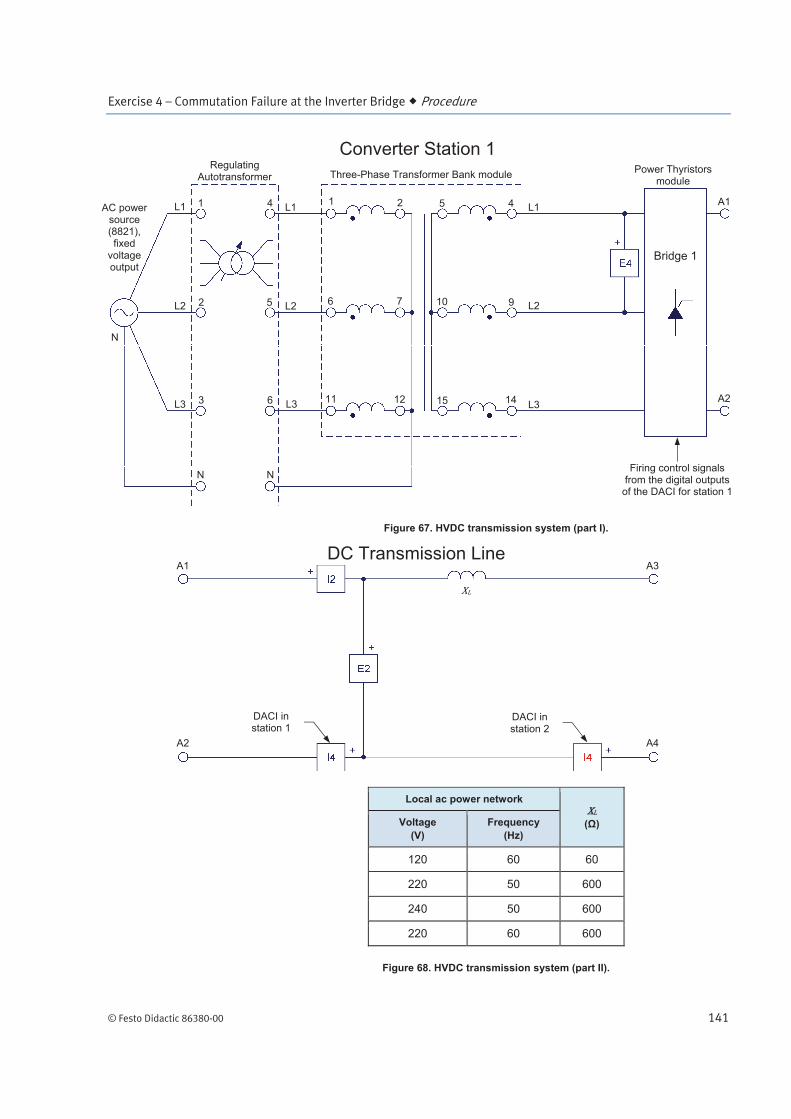
Use the fixed, three-phase ac voltage output of the Power Supply as the ac power source for converter station 1 (left-end station). Use the variable, three-phase ac voltage output of the Power Supply as the ac power source for converter station 2 (right-end station). Use the Three-Phase Transmission
Line module to implement inductance (inductance of the dc line and smoothing inductors). Note that terminals A1 and A2 in Figure 67 connect to the corresponding terminals in Figure 68, while terminals A3 and A4 in Figure 68 connect to the corresponding terminals in Figure 69. Figure 70 shows the detailed connection of the thyristor three-phase bridge in converter station 2 with the meters (E1, I1, E3, and I3) used to measure voltages and currents in this bridge (meter E3 must first be connected to measure the voltage across thyristor of this bridge, as Figure 70 shows).

Exercise 4 – Commutation Failure at the Inverter Bridge Procedure
140 © Festo Didactic 86380-00
a Inputs E1, E2, E3, I1, I2, and I3 of converter stations 1 and 2 (shown in Figure 68 and Figure 70) are all inputs of the DACI used in converter station 1. These inputs are used to measure parameters in the HVDC transmission system. Input E4 of the DACI used in converter station 1 provides synchronization of the firing signals for the Power Thyristors module in station 1. Input E4 of the DACI used in converter station 2 (represented by the red symbol E4 in Figure 69) provides synchronization of the firing signals for the Power Thyristors module in station 2. Input I4 of the DACI used in converter station 1 (represented by the blue symbol I4 in Figure 68) provides dc line current measurement for the current control loop of the thyristor bridge in station 1. Finally, input I4 of the DACI used in converter station 2 (represented by the red symbol I4 in Figure 68) provides dc line current measurement for the current control loop of the thyristor bridge in station 2.
Exercise 4 – Commutation Failure at the Inverter Bridge Procedure
© Festo Didactic 86380-00 141
Figure 67. HVDC transmission system (part I).
Local ac power network
( ) Voltage
(V)
Frequency
(Hz)
120 60 60
220 50 600
240 50 600
220 60 600
Figure 68. HVDC transmission system (part II).
L1
L2
L3
L1
L2
L3
AC power source (8821), fixed
voltage output
N
Three-Phase Transformer Bank module Regulating
Autotransformer
Converter Station 1
L1
L2
L3
Power Thyristors module
A1
A2
Firing control signals from the digital outputs
of the DACI for station 1
DC Transmission Line A1
A2
A3
A4
1
6
11 12
7
2 5
10
15 14
9
4
3
2
N
1
6
5
N
4
Bridge 1
DACI in station 1
DACI in station 2
Exercise 4 – Commutation Failure at the Inverter Bridge Procedure
142 © Festo Didactic 86380-00
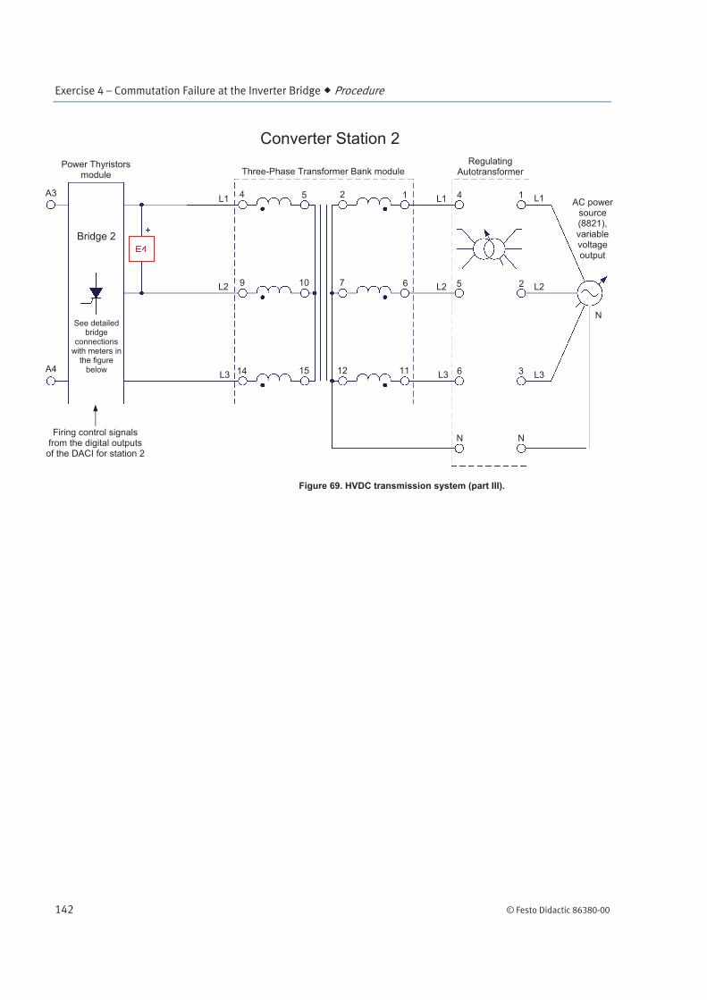
Figure 69. HVDC transmission system (part III).
L1
L2
L3
L1
L2
L3
N
Three-Phase Transformer Bank module Regulating
Autotransformer
L1
L2
L3
Power Thyristors module
A3
A4
Converter Station 2
Firing control signals from the digital outputs
of the DACI for station 2
4
9
15
10
5 2
7
12 11
6
1
6
5
N
4
3
2
N
1 AC power
source (8821), variable voltage output
Bridge 2
See detailed bridge
connections with meters in
the figure below 14
Exercise 4 – Commutation Failure at the Inverter Bridge Procedure
© Festo Didactic 86380-00 143
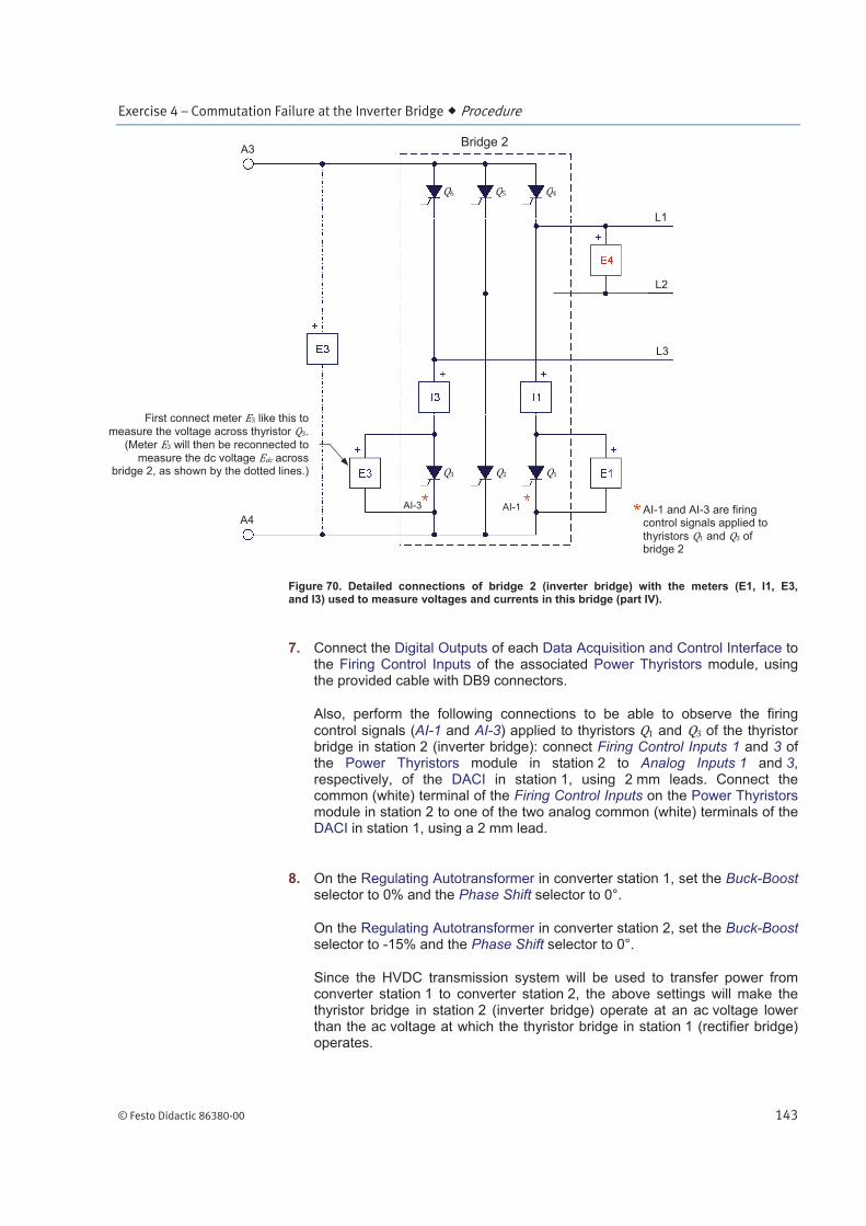
Figure 70. Detailed connections of bridge 2 (inverter bridge) with the meters (E1, I1, E3, and I3) used to measure voltages and currents in this bridge (part IV).
7. Connect the Digital Outputs of each Data Acquisition and Control Interface to the Firing Control Inputs of the associated Power Thyristors module, using the provided cable with DB9 connectors.
Also, perform the following connections to be able to observe the firing
control signals (AI-1 and AI-3) applied to thyristors and of the thyristor bridge in station 2 (inverter bridge): connect Firing Control Inputs 1 and 3 of the Power Thyristors module in station 2 to Analog Inputs 1 and 3, respectively, of the DACI in station 1, using 2 mm leads. Connect the common (white) terminal of the Firing Control Inputs on the Power Thyristors module in station 2 to one of the two analog common (white) terminals of the DACI in station 1, using a 2 mm lead.
8. On the Regulating Autotransformer in converter station 1, set the Buck-Boost selector to 0% and the Phase Shift selector to 0°.
On the Regulating Autotransformer in converter station 2, set the Buck-Boost selector to -15% and the Phase Shift selector to 0°.
Since the HVDC transmission system will be used to transfer power from converter station 1 to converter station 2, the above settings will make the thyristor bridge in station 2 (inverter bridge) operate at an ac voltage lower than the ac voltage at which the thyristor bridge in station 1 (rectifier bridge) operates.
First connect meter like this to
measure the voltage across thyristor .
(Meter will then be reconnected to
measure the dc voltage across bridge 2, as shown by the dotted lines.)
L1
L2
L3
A3
A4
Bridge 2
AI-3 AI-1 AI-1 and AI-3 are firing control signals applied to
thyristors and of bridge 2
Exercise 4 – Commutation Failure at the Inverter Bridge Procedure
144 © Festo Didactic 86380-00
9. In LVDAC-EMS, open the HVDC Transmission System Control window. A dialog box appears. Select the serial number of the DACI that is used to control thyristor bridge 1 (i.e., the serial number of the thyristor bridge in converter station 1, recorded in step 6), then click the OK button to close the dialog box and open the HVDC Transmission System Control window.
In the HVDC Transmission System Control window, make the following settings:
Set the Function parameter to Monopolar HVDC Transmission System.
Set the Control Type parameter to Linked (Rectifier = Bridge 1). This makes bridge 1 operate as a rectifier and the current command of its
current control loop equal to the current command of the HVDC transmission system. This also makes bridge 2 operate as an inverter and the current command of its current control loop equal to minus the current margin ) of the HVDC transmission system.
Set the Rectifier Current Command parameter to 0.3 pu by entering the adequate value in the field next to this parameter or by using the Rectifier Current Command knob in the lower left corner of the
window. This sets the current command of the HVDC transmission system (i.e., the current command of the current control loop at bridge 1, which is set to operate as a rectifier) to 0.3 pu.
Set the Current Margin I parameter to 0.05 pu. This sets the current
margin of the HVDC transmission system to 0.05 pu. Therefore, the current command of the current control loop at bridge 2 (inverter bridge) is set to 0.25 pu (0.3 pu – 0.05 pu = 0.25 pu).
Leave the other parameters set to their default values.
Start the Monopolar HVDC Transmission System function by clicking the Start/Stop button or by setting the Status parameter to Started.
10. In LVDAC-EMS, open the Metering window. A dialog box appears. Select the serial number of the DACI that is used to perform parameter measurements in the HVDC transmission system [i.e., the same DACI that is used to control the thyristor bridge (bridge 1) in converter station 1], then click the OK button to close the dialog box and open the Metering window.
In the Metering window, set three meters to measure the dc line
current (I2) and voltage (E2), and the power transferred [PQS2 (E2,I2)] via the transmission line.
Exercise 4 – Commutation Failure at the Inverter Bridge Procedure
© Festo Didactic 86380-00 145
Extinction angle versus the firing angle
In this section, you will observe the effect which the value of the firing angle of the inverter bridge has on the extinction angle and the likelihood of commutation failures in this bridge.
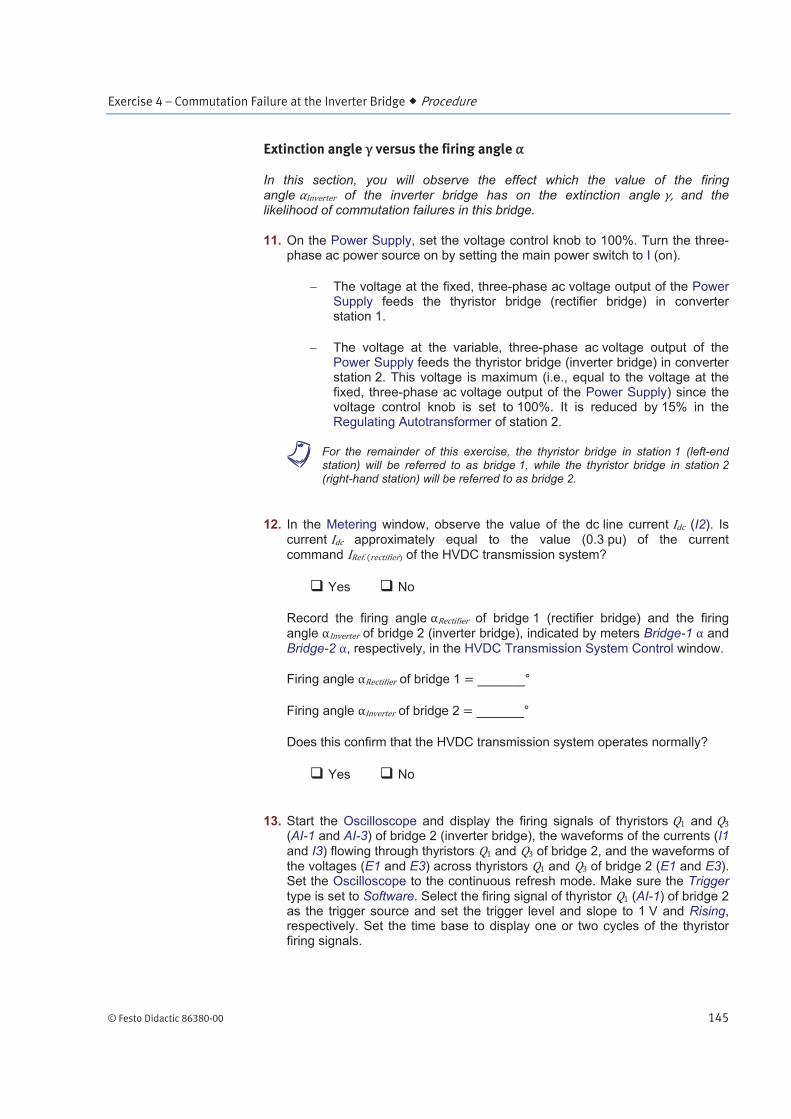
11. On the Power Supply, set the voltage control knob to 100%. Turn the three-phase ac power source on by setting the main power switch to I (on).
The voltage at the fixed, three-phase ac voltage output of the Power Supply feeds the thyristor bridge (rectifier bridge) in converter station 1.
The voltage at the variable, three-phase ac voltage output of the Power Supply feeds the thyristor bridge (inverter bridge) in converter station 2. This voltage is maximum (i.e., equal to the voltage at the fixed, three-phase ac voltage output of the Power Supply) since the voltage control knob is set to 100%. It is reduced by 15% in the Regulating Autotransformer of station 2.
a For the remainder of this exercise, the thyristor bridge in station 1 (left-end station) will be referred to as bridge 1, while the thyristor bridge in station 2 (right-hand station) will be referred to as bridge 2.
12. In the Metering window, observe the value of the dc line current (I2). Is current approximately equal to the value (0.3 pu) of the current command of the HVDC transmission system?
Yes No
Record the firing angle of bridge 1 (rectifier bridge) and the firing angle of bridge 2 (inverter bridge), indicated by meters Bridge-1 and
Bridge-2 , respectively, in the HVDC Transmission System Control window.
Firing angle of bridge 1 °
Firing angle of bridge 2 °
Does this confirm that the HVDC transmission system operates normally?
Yes No
13. Start the Oscilloscope and display the firing signals of thyristors and (AI-1 and AI-3) of bridge 2 (inverter bridge), the waveforms of the currents (I1
and I3) flowing through thyristors and of bridge 2, and the waveforms of the voltages (E1 and E3) across thyristors and of bridge 2 (E1 and E3). Set the Oscilloscope to the continuous refresh mode. Make sure the Trigger type is set to Software. Select the firing signal of thyristor (AI-1) of bridge 2 as the trigger source and set the trigger level and slope to 1 V and Rising, respectively. Set the time base to display one or two cycles of the thyristor firing signals.
Exercise 4 – Commutation Failure at the Inverter Bridge Procedure
146 © Festo Didactic 86380-00
14. Decrease the maximum (limit) value of the firing angle of bridge 2 (inverter bridge) to 135°. To do this, set the Inverter Limit parameter of Bridge 2 in the HVDC Transmission System Control window to 135. Observe
that this causes the firing angle (meter Bridge-2 ) to pass from 165° to 135°.
Observe the firing signals and the voltage and current waveforms displayed on the Oscilloscope. Describe what happens when thyristor in bridge 2 (inverter bridge) is fired. Explain briefly.
On the Oscilloscope, observe the waveforms of the voltages across
thyristors and of bridge 2. Notice that when either of these two thyristors turns off, the voltage across the thyristor passes from zero to a negative value, thereby applying a reverse bias to the thyristor for a significant part of the ac power cycle.
Using the Oscilloscope, determine the extinction angle (i.e., the angular interval during which a reverse bias is applied to the outgoing thyristor). Record the value below.
Extinction angle ( = 135°) °
Are commutation failures likely to occur in a three-phase thyristor bridge operating under the current conditions? Explain.
15. Increase the maximum (limit) value of the firing angle of bridge 2 (inverter bridge) to 170° while observing the waveforms displayed on the
Exercise 4 – Commutation Failure at the Inverter Bridge Procedure
© Festo Didactic 86380-00 147
Oscilloscope. Notice that this causes the firing angle to pass from 135° to 170°. What happens to the voltages across thyristors and
and to the extinction angle ?
Using the Oscilloscope, determine the extinction angle . Record the value below.
Extinction angle ( = 170°) °
From your observations, what effect does increasing the maximum (limit)
value of the firing angle of bridge 2 (inverter bridge) have on the likelihood of commutation failures in this bridge? Explain.
Exercise 4 – Commutation Failure at the Inverter Bridge Procedure
148 © Festo Didactic 86380-00
Commutation overlap
In this section, you will measure the duration of the commutation overlap for a given value of the dc line current . You will observe the effect of the commutation overlap on the waveform of the dc voltage across the inverter bridge. You will then observe the effect that increasing the dc current or reducing the ac voltage at the inverter bridge has on the duration of the commutation overlap.
Measuring the duration of the commutation overlap
16. In the HVDC Transmission System Control window, set the maximum (limit) value of the firing angle of bridge 2 (inverter bridge) to 165°. Notice
that this causes the firing angle to pass from 170° to 165°.
Set the Oscilloscope to display the firing signal (AI-1) of thyristor in bridge 2 (inverter bridge), the waveforms of the currents (I1 and I3) flowing
through thyristors and in bridge 2, and the waveform of the voltage (E3) across thyristor in bridge 2. (Turn the other Oscilloscope channels off.) Set the Oscilloscope time base to 0.2 ms/div.
Place the Oscilloscope in the single refresh mode. Set the Trigger type to
Hardware. Select the firing signal (AI-1) of thyristor as the trigger source and set the trigger level and slope to 1 V and Rising, respectively.
17. On the Oscilloscope, click the Single Refresh button to start a single-acquisition cycle. The Oscilloscope display should be refreshed with the waveforms of the currents through thyristors and , as well as the voltage
across thyristor , at the instant when thyristor is fired.
Observe that when thyristor is fired, the current flowing through bridge 2
does not transfer instantaneously from thyristor (outgoing thyristor) to thyristor (incoming thyristor). Instead, the current briefly flows through both thyristors and (i.e., commutation overlap occurs), then thyristor turns
off completely and the current flowing through becomes null (zero). Notice that a brief downward spike appears in the waveform of the current flowing
through thyristor just before this current becomes null (i.e., the current flowing through thyristor momentarily reverses direction before thyristor turns off completely).
Measure the duration of the commutation overlap (i.e., the time interval
between the instant at which current starts flowing through thyristor and the instant at which the negative spike in the current flowing through
thyristor reaches the maximum value).
Commutation overlap duration ( = 0.3 pu, = 100%) ms
Determine the overlap angle .
Overlap angle °
Exercise 4 – Commutation Failure at the Inverter Bridge Procedure
© Festo Didactic 86380-00 149
Effect of the commutation overlap on the waveform of the dc voltage across the inverter bridge
18. Stop the Monopolar HVDC Transmission System function by clicking the Start/Stop button or by setting the Status parameter to Stopped.
On the Power Supply, turn the three-phase ac power source off by setting the main power switch to the O (off) position. (Leave the 24 V ac power source of the Power Supply turned on.)
(Refer to Figure 70.) Disconnect input E3 of the DACI used in converter
station 1 from thyristor of bridge 2 (inverter bridge). Reconnect input E3 across bridge 2 as indicated by the dotted lines in Figure 70 in order to
measure the voltage across bridge 2.
19. Start the Monopolar HVDC Transmission System function. On the Power Supply, turn the three-phase ac power source on.
20. On the Oscilloscope, click the Single Refresh button to start a single-acquisition cycle, and observe the waveforms of the currents through
thyristors and , as well as the voltage across bridge 2 (inverter bridge) when thyristor is fired. Notice that a small notch is present in
voltage during the commutation overlap. Explain why.
Effect of the dc line current value on the duration of the commutation overlap
21. Stop the Monopolar HVDC Transmission System function by clicking the Start/Stop button or by setting the Status parameter to Stopped.
On the Power Supply, turn the three-phase ac power source off by setting the main power switch to the O (off) position. (Leave the 24 V ac power source of the Power Supply turned on.)
(Refer to Figure 70.) Reconnect input E3 of the DACI used in converter
station 1 to measure the voltage across thyristor in bridge 2 (inverter bridge).
22. Start the HVDC transmission system. On the Power Supply, turn the three-phase ac power source on.

Exercise 4 – Commutation Failure at the Inverter Bridge Procedure
150 © Festo Didactic 86380-00
23. Place the Oscilloscope in the continuous refresh mode.
While observing the waveforms on the Oscilloscope screen, gradually increase the current command of the HVDC transmission system to 1.0 pu.
What happens to the duration of the commutation overlap, and therefore to
the overlap angle , when the dc line current increases? Why?
24. Place the Oscilloscope in the single refresh mode. Measure the duration of the commutation overlap when the current is 1.0 pu.
Commutation overlap duration ( = 1.0 pu, = 100%) ms
Determine the overlap angle .
Overlap angle °
Compare the value of the overlap angle obtained with a current of 1.0 pu
(recorded above) to that obtained with a current of 0.3 pu (recorded in step 17).

Exercise 4 – Commutation Failure at the Inverter Bridge Procedure
© Festo Didactic 86380-00 151
25. From your observations, what is the effect of increasing the current on the overlap angle , the extinction angle , and the likelihood of commutation failures in bridge 2 (inverter bridge)? Explain.
Exercise 4 – Commutation Failure at the Inverter Bridge Procedure
152 © Festo Didactic 86380-00
Effect of the ac voltage at the inverter bridge on the duration of the commutation overlap
26. Place the Oscilloscope in the continuous refresh mode.
27. While observing the waveforms on the Oscilloscope screen, slowly reduce the ac voltage at bridge 2 (inverter bridge) down to 60% of its original value by setting the control knob of the Power Supply to approximately 60%.
What happens to the duration of the commutation overlap, and therefore to the overlap angle , when the ac voltage at bridge 2 decreases? Why?
28. Place the Oscilloscope in the single refresh mode. Measure the duration of the commutation overlap when the ac voltage at bridge 2 (inverter bridge) is decreased to approximately 60%.
Commutation overlap duration ( = 1.0 pu, = 60%) ms
Determine the overlap angle .
Overlap angle °
Compare the value of the overlap angle obtained with an ac voltage of 60% at bridge 2 (recorded above) to that obtained with an ac voltage of 100% at bridge 2 (recorded in step 24).
Exercise 4 – Commutation Failure at the Inverter Bridge Procedure
© Festo Didactic 86380-00 153
29. From your observations, what is the effect of decreasing the ac voltage at
bridge 2 (inverter bridge) on the overlap angle , the extinction angle and the likelihood of commutation failures in bridge 2 (inverter bridge)? Explain.
30. In the HVDC Transmission System Control window, gradually decrease the
current command to 0.3 pu. Stop the Monopolar HVDC Transmission System function by clicking the Start/Stop button or by setting the Status parameter to Stopped.
Effect of a commutation failure at the inverter bridge of an HVDC transmission system
In this section, you will produce a commutation failure at the inverter bridge of an HVDC transmission system and observe what happens to the system parameters.
31. On the Power Supply, turn the three-phase ac power source off by setting the main power switch to the O (off) position. (Leave the 24 V ac power source of the Power Supply turned on.)
Refer to Figure 71, Figure 72, and Figure 73. Modify the meter connections in order to be able to measure the line-to-line voltage and line current at the ac side of both thyristor three-phase bridges in the HVDC transmission system.

Exercise 4 – Commutation Failure at the Inverter Bridge Procedure
154 © Festo Didactic 86380-00
Figure 71. HVDC transmission system (part I).
Local ac power network
( ) Voltage
(V)
Frequency
(Hz)
120 60 60
220 50 600
240 50 600
220 60 600
Figure 72. HVDC transmission system (part II).
L1
L2
L3
L1
L2
L3
AC power source (8821), fixed
voltage output
N
Three-Phase Transformer Bank module Regulating
Autotransformer
Converter Station 1
L1
L2
L3
Power Thyristors module
A1
A2
Firing control signals from the digital outputs
of the DACI for station 1
DC Transmission Line A1
A2
A3
A4
1
6
11 12
7
2 5
10
15 14
9
4
3
2
N
1
6
5
N
4
Bridge 1
DACI in station 1
DACI in station 2
Exercise 4 – Commutation Failure at the Inverter Bridge Procedure
© Festo Didactic 86380-00 155
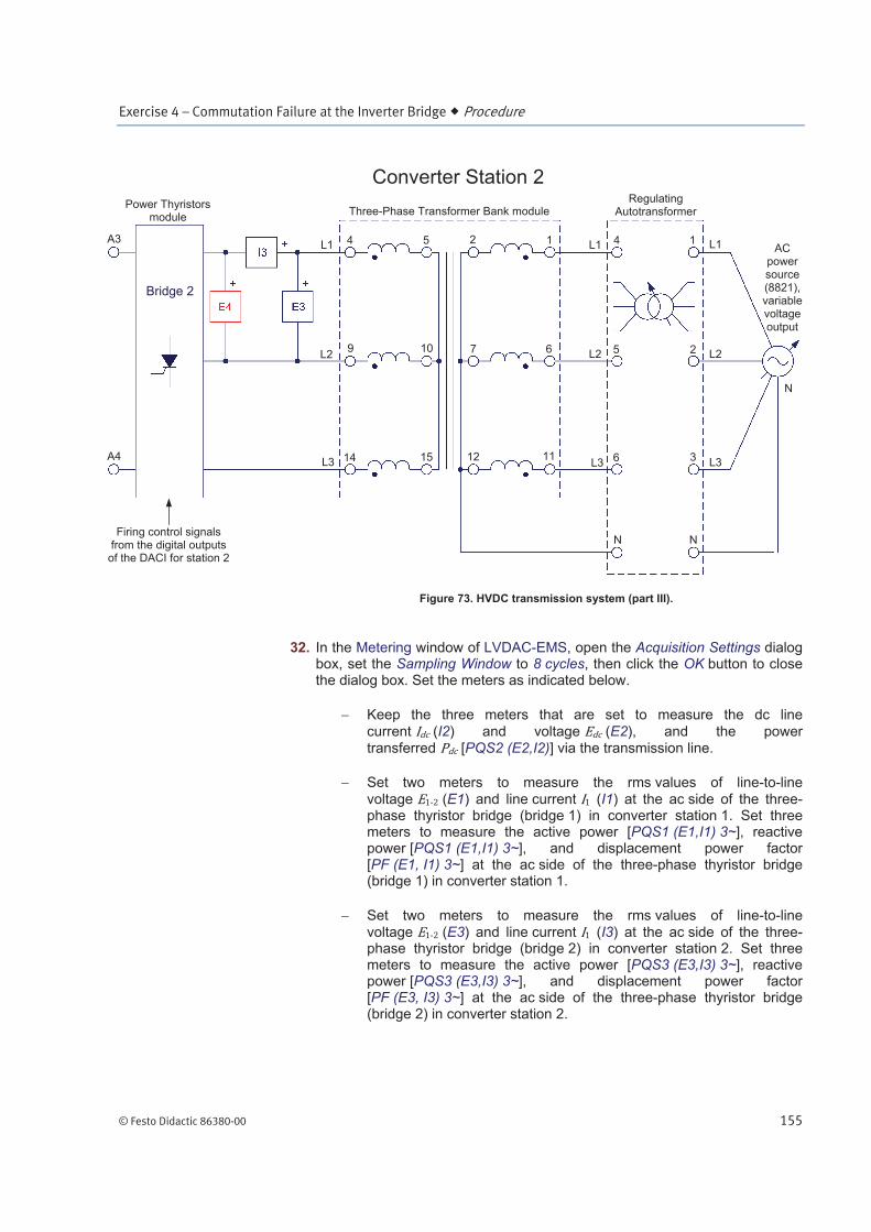
Figure 73. HVDC transmission system (part III).
32. In the Metering window of LVDAC-EMS, open the Acquisition Settings dialog box, set the Sampling Window to 8 cycles, then click the OK button to close the dialog box. Set the meters as indicated below.
Keep the three meters that are set to measure the dc line
current (I2) and voltage (E2), and the power transferred [PQS2 (E2,I2)] via the transmission line.
Set two meters to measure the rms values of line-to-line
voltage (E1) and line current (I1) at the ac side of the three-phase thyristor bridge (bridge 1) in converter station 1. Set three meters to measure the active power [PQS1 (E1,I1) 3~], reactive power [PQS1 (E1,I1) 3~], and displacement power factor [PF (E1, I1) 3~] at the ac side of the three-phase thyristor bridge (bridge 1) in converter station 1.
Set two meters to measure the rms values of line-to-line
voltage (E3) and line current (I3) at the ac side of the three-phase thyristor bridge (bridge 2) in converter station 2. Set three meters to measure the active power [PQS3 (E3,I3) 3~], reactive power [PQS3 (E3,I3) 3~], and displacement power factor [PF (E3, I3) 3~] at the ac side of the three-phase thyristor bridge (bridge 2) in converter station 2.
L1
L2
L3
L1
L2
L3
N
Three-Phase Transformer Bank module Regulating
Autotransformer
L1
L2
L3
Power Thyristors module
A3
A4
Converter Station 2
Firing control signals from the digital outputs
of the DACI for station 2
4
9
14 15
10
5 2
7
12 11
6
1
6
5
N
4
3
2
N
1 AC
power source (8821), variablevoltage output
Bridge 2
Exercise 4 – Commutation Failure at the Inverter Bridge Procedure
156 © Festo Didactic 86380-00
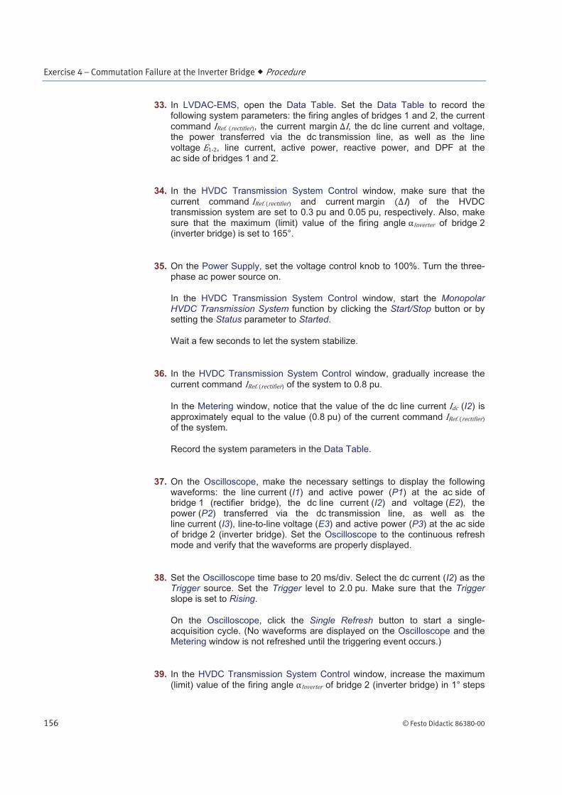
33. In LVDAC-EMS, open the Data Table. Set the Data Table to record the following system parameters: the firing angles of bridges 1 and 2, the current command , the current margin , the dc line current and voltage, the power transferred via the dc transmission line, as well as the line voltage , line current, active power, reactive power, and DPF at the ac side of bridges 1 and 2.
34. In the HVDC Transmission System Control window, make sure that the
current command and current margin ) of the HVDC transmission system are set to 0.3 pu and 0.05 pu, respectively. Also, make
sure that the maximum (limit) value of the firing angle of bridge 2 (inverter bridge) is set to 165°.
35. On the Power Supply, set the voltage control knob to 100%. Turn the three-phase ac power source on.
In the HVDC Transmission System Control window, start the Monopolar HVDC Transmission System function by clicking the Start/Stop button or by setting the Status parameter to Started.
Wait a few seconds to let the system stabilize.
36. In the HVDC Transmission System Control window, gradually increase the
current command of the system to 0.8 pu.
In the Metering window, notice that the value of the dc line current (I2) is approximately equal to the value (0.8 pu) of the current command of the system.
Record the system parameters in the Data Table.
37. On the Oscilloscope, make the necessary settings to display the following waveforms: the line current (I1) and active power (P1) at the ac side of bridge 1 (rectifier bridge), the dc line current (I2) and voltage (E2), the power (P2) transferred via the dc transmission line, as well as the line current (I3), line-to-line voltage (E3) and active power (P3) at the ac side of bridge 2 (inverter bridge). Set the Oscilloscope to the continuous refresh mode and verify that the waveforms are properly displayed.
38. Set the Oscilloscope time base to 20 ms/div. Select the dc current (I2) as the Trigger source. Set the Trigger level to 2.0 pu. Make sure that the Trigger slope is set to Rising.
On the Oscilloscope, click the Single Refresh button to start a single-acquisition cycle. (No waveforms are displayed on the Oscilloscope and the Metering window is not refreshed until the triggering event occurs.)
39. In the HVDC Transmission System Control window, increase the maximum (limit) value of the firing angle of bridge 2 (inverter bridge) in 1° steps
Exercise 4 – Commutation Failure at the Inverter Bridge Procedure
© Festo Didactic 86380-00 157
until a commutation failure occurs (i.e., until the Oscilloscope display is refreshed due to the occurrence of the triggering event). This should occur when the maximum (limit) value of the firing angle of bridge 2 is approximately 173°.
Record the maximum (limit) value of the firing angle at which the commutation failure occurs
Maximum (limit) firing angle at bridge 2 °
40. Observe the waveforms displayed on the Oscilloscope. Explain what happens when a commutation failure occurs at bridge 2 (inverter bridge) and how the HVDC transmission system reacts.
41. Make sure the Metering window is in the continuous refresh mode. Record the system parameters in the Data Table.
Examine the recorded data to understand the effect of a commutation failure and the ensuing short-circuit at bridge 2 (inverter bridge) of the HVDC transmission system.
Does the dc line current remain at its original value (0.8 pu) (with an exception being made for the initial transient spike)?
Yes No
Is the dc line voltage nearly zero, and thus the dc power transferred via the transmission line virtually null? Explain.
Exercise 4 – Commutation Failure at the Inverter Bridge Procedure
158 © Festo Didactic 86380-00
Does current still flow at the ac side of bridge 1 (rectifier bridge)? Why?
Does current still flow at the ac side of bridge 2 (inverter bridge)? Why?
42. In the Metering window, observe that the displayed values are virtually constant, indicating that once a commutation failure occurs at bridge 2 (inverter bridge), the ensuing short-circuit is permanent.
Decrease the maximum (limit) value of the firing angle of bridge 2 to 165° (inverter bridge) in 1° steps. Notice that when the maximum (limit) firing angle at bridge 2 has decreased to a certain value, the short-circuit at the dc side of bridge 2 ceases (i.e., the dc line current and voltage, and the power transferred via the transmission line return to their initial values, recorded in step 36).
Did the other system parameters (line current, voltage, power, and DFP) at the ac side of each bridge return back to their original values?
Yes No
Commutation failure resulting from a voltage decrease at the ac side of the inverter bridge of an HVDC transmission system
43. Set the maximum (limit) value of the firing angle of bridge 2 to 2° or 3° less than the value which created a commutation failure in the previous section (recorded in step 39). This will provide the system with a minimal safety margin against commutation failure.
44. On the Oscilloscope, click the Single Refresh button to start a single-acquisition cycle. (No waveforms are displayed on the Oscilloscope and the Metering window is not refreshed until a triggering event occurs.)
45. On the Power Supply, momentarily reduce the ac voltage at bridge 2 (inverter bridge) by quickly setting the voltage control knob to the 50% position and returning it to the 100% position. Observe that a
Exercise 4 – Commutation Failure at the Inverter Bridge Conclusion
© Festo Didactic 86380-00 159
commutation failure occurs (i.e., the Oscilloscope display is refreshed due to the occurrence of the triggering event).
Observe the waveforms displayed on the Oscilloscope. Explain why a commutation failure occurred at bridge 2.
46. On the Power Supply, turn the three-phase ac power source off by setting the main power switch to the O (off) position. Turn the 24 V ac power source of the Power Supply off. Close the LVDAC-EMS software. Disconnect all leads and return them to their storage location.
In this exercise, you learned how thyristor commutation is performed in thyristor three-phase bridges. You learned that the six thyristors in a thyristor three-phase bridge are fired in such a way that at any given instant, one thyristor in the common-anode thyristor group and one thyristor in the common-anode thyristor group are both conducting current, thereby allowing current to flow continuously through the bridge. You learned that when a commutation failure occurs in a thyristor three-phase bridge, the dc side of the bridge becomes short-circuited 60° later (i.e., when the next thyristor is fired). This causes the dc voltage across the transmission line to drop to zero, and thus the power transferred through the system to drop to zero. You learned that commutation failures are more likely to occur in thyristor three-phase bridges that operate as
inverters because as the firing angle approaches 180°, the extinction angle becomes closer to the thyristor extinction angle . You also learned that commutation overlap in thyristor three-phase bridges reduces the extinction angle and thus increases the likelihood of commutation failures.
1. Explain how the six thyristors in a thyristor three-phase bridge are fired to allow current to flow continuously through the bridge.
CONCLUSION
REVIEW QUESTIONS

Exercise 4 – Commutation Failure at the Inverter Bridge Review Questions
160 © Festo Didactic 86380-00
2. What is meant by “commutation failure”? Describe the effect a commutation
failure has on the dc current and voltage , and on the dc power transferred via the transmission line, and explain this effect.
3. State the two conditions required for commutation to be successful (i.e., to avoid a commutation failure) and explain these conditions.
4. What is meant by “commutation overlap”? Explain the effect that
commutation overlap has on the extinction angle .

Exercise 4 – Commutation Failure at the Inverter Bridge Review Questions
© Festo Didactic 86380-00 161
5. What happens to the overlap angle , the extinction angle , and the likelihood of commutation failures when the current flowing through the dc side of a thyristor three-phase bridge increases? What happens when the voltage at the ac side of the bridge decreases due to a fault in the ac power system connected to this bridge? Explain.