HVAC Influence on Vapor Intrusion in Commercial and Industrial...
12
HVAC Influence on Vapor Intrusion in Commercial and Industrial Buildings David Shea, P.E., Claire G. Lund, P.E., Bradley A. Green, P.G. Sanborn, Head & Associates, Inc., 20 Foundry St., Concord, NH 03301 ABSTRACT Heating, ventilating, and air conditioning (HVAC) systems play a significant role in vapor intrusion potential and its mitigation for commercial and industrial buildings. An understanding of HVAC system design and operating conditions is important to evaluating the potential influence on vapor intrusion, air quality patterns in the building space, and options for mitigation. While building conditions influencing vapor intrusion in residential structures do not typically include active ventilation with engineered systems and are therefore less systematic and more random, buildings equipped with engineered HVAC systems represent more controlled environments with rates of air exchange within specified limits. Thus, for many systems, engineered HVAC adjustments can be considered as a component of mitigation based on projected costs and predictable effects on indoor air quality. After presenting an overview of common HVAC components and how they influence indoor air quality by affecting subslab-to- indoor air pressure gradients and air exchange, this paper describes several case examples of the role of HVAC operations in vapor intrusion assessment and mitigation. This paper presents favorable and unfavorable effects of HVAC operations on vapor intrusion, even in so-called “positive pressure” building space, and the cost vs. benefits offered by adjustments to HVAC systems for reducing vapor intrusion potential and improving indoor air quality. These findings can be used to help formulate and guide vapor intrusion assessment and mitigation strategies for commercial and industrial buildings. INTRODUCTION Intrusion of volatile organic compounds (VOCs) into commercial and industrial buildings has not been as commonly addressed in the literature compared with residential structures. This is because vapor intrusion investigation and mitigation projects have involved far more residential structures than non-residential buildings. 1 It should be recognized that there are important differences between residential and commercial and industrial buildings with respect to how vapor intrusion from the subsurface may be realized and mitigated. 2 These differences can include, but are not limited to, building footprint size and volume, foundation/floor slab construction, and air exchange. In addition, present or former operations in commercial and industrial buildings may result in releases directly to the subsurface beneath the building, yielding subslab vapor concentrations out of proportion to what is typically found sourced from dissolved phase VOCs. With respect to air exchange, a key difference from residential structures is that many commercial/industrial structures are served by engineered heating, ventilating, and air conditioning (HVAC) systems designed for active air exchange, and in some cases, positive pressure relative to the outdoors. However, engineered HVAC systems may either increase or
-
Upload
phamkhuong -
Category
Documents
-
view
215 -
download
0
Transcript of HVAC Influence on Vapor Intrusion in Commercial and Industrial...
HVAC Influence on Vapor Intrusion in Commercial and
Industrial Buildings
David Shea, P.E., Claire G. Lund, P.E., Bradley A. Green, P.G. Sanborn, Head & Associates, Inc., 20 Foundry St., Concord, NH 03301
ABSTRACT
Heating, ventilating, and air conditioning (HVAC) systems play a significant role in vapor
intrusion potential and its mitigation for commercial and industrial buildings. An understanding
of HVAC system design and operating conditions is important to evaluating the potential
influence on vapor intrusion, air quality patterns in the building space, and options for
mitigation. While building conditions influencing vapor intrusion in residential structures do not
typically include active ventilation with engineered systems and are therefore less systematic and
more random, buildings equipped with engineered HVAC systems represent more controlled
environments with rates of air exchange within specified limits. Thus, for many systems,
engineered HVAC adjustments can be considered as a component of mitigation based on
projected costs and predictable effects on indoor air quality. After presenting an overview of
common HVAC components and how they influence indoor air quality by affecting subslab-to-
indoor air pressure gradients and air exchange, this paper describes several case examples of the
role of HVAC operations in vapor intrusion assessment and mitigation. This paper presents
favorable and unfavorable effects of HVAC operations on vapor intrusion, even in so-called
“positive pressure” building space, and the cost vs. benefits offered by adjustments to HVAC
systems for reducing vapor intrusion potential and improving indoor air quality. These findings
can be used to help formulate and guide vapor intrusion assessment and mitigation strategies for
commercial and industrial buildings.
INTRODUCTION
Intrusion of volatile organic compounds (VOCs) into commercial and industrial buildings has
not been as commonly addressed in the literature compared with residential structures. This is
because vapor intrusion investigation and mitigation projects have involved far more residential
structures than non-residential buildings.1 It should be recognized that there are important
differences between residential and commercial and industrial buildings with respect to how
vapor intrusion from the subsurface may be realized and mitigated.2 These differences can
include, but are not limited to, building footprint size and volume, foundation/floor slab
construction, and air exchange. In addition, present or former operations in commercial and
industrial buildings may result in releases directly to the subsurface beneath the building,
yielding subslab vapor concentrations out of proportion to what is typically found sourced from
dissolved phase VOCs.
With respect to air exchange, a key difference from residential structures is that many
commercial/industrial structures are served by engineered heating, ventilating, and air
conditioning (HVAC) systems designed for active air exchange, and in some cases, positive
pressure relative to the outdoors. However, engineered HVAC systems may either increase or

decrease vapor intrusion potential depending primarily on how these systems affect air pressure
gradients across the building envelope. Therefore, an understanding of HVAC system design and
operation is crucial to vapor intrusion assessment and potential mitigation.
When HVAC system operations are understood, modifications can be considered and have been
effective in reducing vapor intrusion and improving indoor air quality in commercial and
industrial buildings.3 Assessment methods recently used to distinguish indoor VOC sources from
vapor intrusion have included building air pressure cycling in conjunction with sampling indoor
air to evaluate vapor intrusion realization under both positive and negative pressure conditions.4
After providing a basic summary of common HVAC system components, the objective of this
paper is to call attention to some of the key factors that can have favorable or unfavorable
influences on vapor intrusion. The influence of HVAC systems is exemplified through several
case examples that show how HVAC assessment played a prominent role in understanding the
contributing factors to vapor intrusion and how HVAC adjustments could reduce indoor VOC
concentrations and improve indoor air quality.
HVAC BASICS
HVAC systems refer to the mechanical systems that heat, cool, ventilate, filter, humidify, or
dehumidify air in a room or building. These systems come in many types and configurations, but
can be commonly organized into the following categories:5
1. Central or “all-air” systems, whereby a common or central air handling unit supplies
heated or cooled air to multiple spaces/rooms in a building via a duct network.
2. Centralized fluid based systems, whereby a fluid, typically water, is circulated around a
building to provide heating or cooling.
3. Decentralized or unitary systems, which consist of dedicated heating or cooling
equipment for particular building spaces/rooms, such as packaged room air conditioning
units or heat pumps.
4. Exhaust fan systems: kitchens, rest rooms, laboratories, industrial processes.
This paper addresses “all-air” systems and exhaust fans, which are commonly installed in larger
commercial office and industrial buildings. Figure 1 shows the main components of a typical
“all-air” system.
In a typical “all-air” system, outdoor air is drawn into the air handling unit (AHU) and mixed
with air recycled from the building space, which is known as return air. The mixed outdoor and
return air then passes through filters and across heating and cooling coils before entering the fan,
which discharges the conditioned air, known as supply air, to the building space through a
network of supply ductwork and diffusers, typically installed in the ceiling. Return air is recycled
back to the AHU through a separate duct network connected to intake registers inside the
building. A portion of the return air is typically discharged from the building, and is referred to
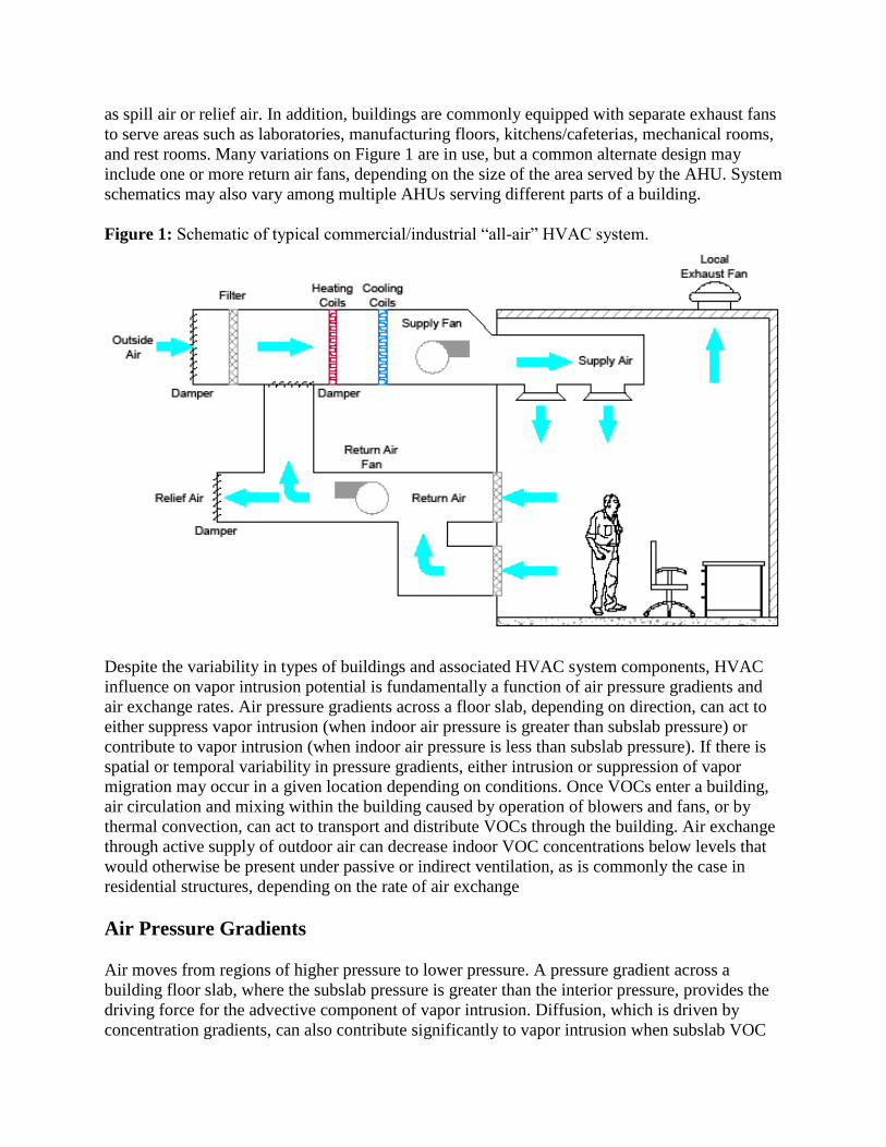
as spill air or relief air. In addition, buildings are commonly equipped with separate exhaust fans
to serve areas such as laboratories, manufacturing floors, kitchens/cafeterias, mechanical rooms,
and rest rooms. Many variations on Figure 1 are in use, but a common alternate design may
include one or more return air fans, depending on the size of the area served by the AHU. System
schematics may also vary among multiple AHUs serving different parts of a building.
Figure 1: Schematic of typical commercial/industrial “all-air” HVAC system.
Despite the variability in types of buildings and associated HVAC system components, HVAC
influence on vapor intrusion potential is fundamentally a function of air pressure gradients and
air exchange rates. Air pressure gradients across a floor slab, depending on direction, can act to
either suppress vapor intrusion (when indoor air pressure is greater than subslab pressure) or
contribute to vapor intrusion (when indoor air pressure is less than subslab pressure). If there is
spatial or temporal variability in pressure gradients, either intrusion or suppression of vapor
migration may occur in a given location depending on conditions. Once VOCs enter a building,
air circulation and mixing within the building caused by operation of blowers and fans, or by
thermal convection, can act to transport and distribute VOCs through the building. Air exchange
through active supply of outdoor air can decrease indoor VOC concentrations below levels that
would otherwise be present under passive or indirect ventilation, as is commonly the case in
residential structures, depending on the rate of air exchange
Air Pressure Gradients
Air moves from regions of higher pressure to lower pressure. A pressure gradient across a
building floor slab, where the subslab pressure is greater than the interior pressure, provides the
driving force for the advective component of vapor intrusion. Diffusion, which is driven by
concentration gradients, can also contribute significantly to vapor intrusion when subslab VOC
concentrations are very high (diffusive transport is not addressed in this paper). Beneath the
overall footprint of a building, subslab pressure relative to indoor pressure can vary significantly,
and even change from positive to negative and vice versa, depending on the characteristics of the
activities and HVAC components throughout the building, wind effects, and barometric pressure
changes.
Where air is actively being removed from a space, areas of low pressure conducive to vapor
intrusion may be present.6 For example, return air systems are typically at lower pressure than
room air pressure. The return air pressure may also be less than the exterior or subslab pressure.
If components of the return air system, such as intake registers, plenums, ductwork, or fan
housings cause localized areas of low pressure inside the building, a pressure gradient may be
present favorable to entry of subslab vapors into the HVAC system where they can subsequently
be recirculated into the building space.
Besides return air systems, any area where more air is actively removed than supplied has the
potential to be at lower pressure relative to the subslab and thus a candidate for vapor intrusion.
In commercial and industrial buildings, areas typically served by exhaust fans, such as
manufacturing floors, laboratories, kitchens/cafeterias, and rest rooms, have the potential to be at
lower air pressure relative to subslab pressure.
Once present in indoor air or HVAC systems, VOCs can be transported and distributed far afield
from the subslab source by interior pressure gradients/air flow patterns.
Air Exchange Rate
The air exchange rate (AER) is defined as how often the air volume in a given space is replaced
by outdoor air. The default AER for commercial buildings assumed by USEPA and many other
state agencies is 1 per hour7, which is reported as conservative. We have observed AERs in
commercial and industrial buildings ranging from near negligible, for example in closed storage
or warehouse space without active HVAC, to up to 10 hr-1
in some clean rooms. In reality, the
AER will vary from area to area of a building depending on the particular design and operation
of the HVAC components serving that particular area.
While AER is commonly used to characterize building ventilation, HVAC design standards8 for
outdoor air supply are specified in terms of either cubic feet per minute (cfm) per person, or cfm
per square foot of building space. Different ventilation requirements apply to different types of
spaces (e.g., offices, stores, shops, hotels), but these typically range from 15 to 20 cfm of outdoor
air per person. The typical outdoor air ventilation rate per unit area ranges from 0.1 to 0.5 cfm
per ft2.
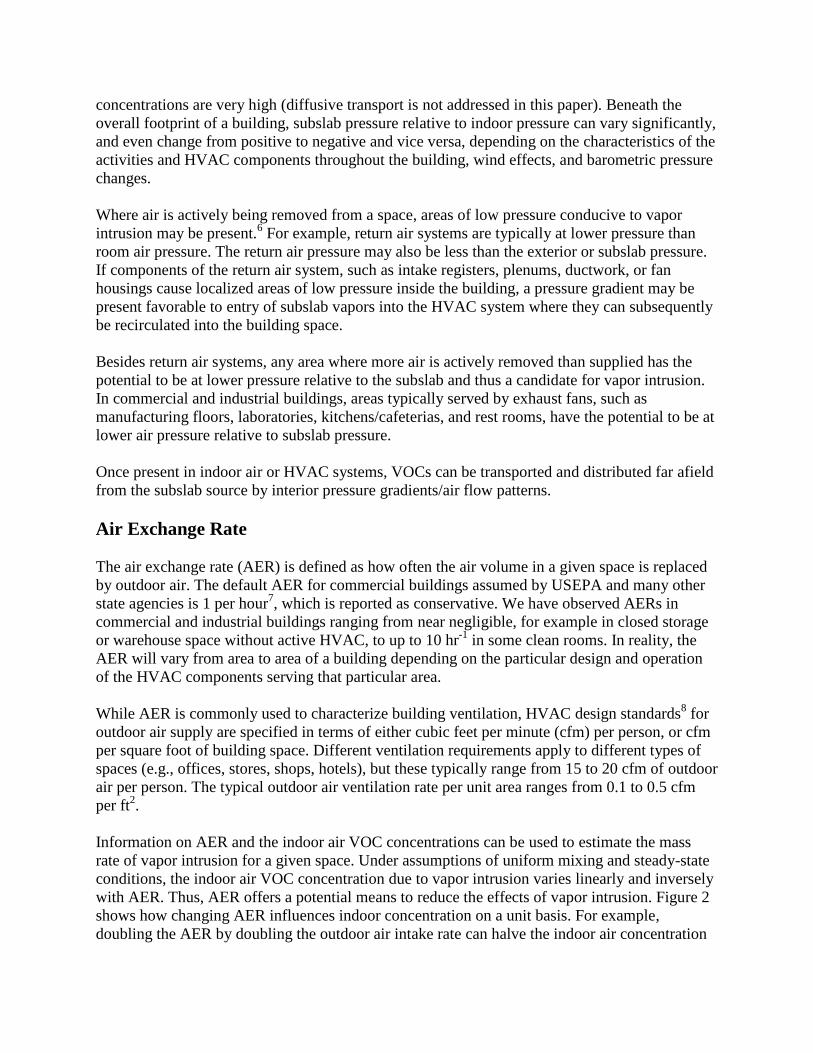
Information on AER and the indoor air VOC concentrations can be used to estimate the mass
rate of vapor intrusion for a given space. Under assumptions of uniform mixing and steady-state
conditions, the indoor air VOC concentration due to vapor intrusion varies linearly and inversely
with AER. Thus, AER offers a potential means to reduce the effects of vapor intrusion. Figure 2
shows how changing AER influences indoor concentration on a unit basis. For example,
doubling the AER by doubling the outdoor air intake rate can halve the indoor air concentration
without materially changing the mass rate of vapor intrusion. For industrial hygienists, the most
common solution to indoor air quality concerns is to increase the ventilation rate.
Figure 2: Influence of outdoor air exchange rate on indoor air concentration.
While VOC source removal is usually the ideal solution to vapor intrusion, modification of AER
can sometimes be an effective way to achieve immediate improvements in indoor air quality
when subslab mitigation will take time or be impractical.
HVAC Modification Costs
HVAC systems can be modified to mitigate vapor intrusion, principally by either increasing
AER and/or increasing the interior air pressure of a given space, but the costs and sustainability
of such modifications are strongly dependent on a variety of factors, including whether existing
equipment has available capacity to meet AER or pressurization goals, how air-tight the building
may be, and occupant comfort. If new or modified equipment is required, capital costs are
building- and space-specific, but can be as much as $100,000 or more for an air handling unit.
The building-specific nature of HVAC capital costs is reflected in the cost estimate range of $1
to $15 per ft2 published in the 2007 ITRC guidance.
7
Long-term operating costs are also important to consider in evaluating HVAC modifications for
vapor intrusion mitigation. For example, in New England, the average annual cost to condition
outdoor air has been reported to range from $6 to $12 per cfm.9 ITRC reports that additional
operating costs to modify HVAC systems to mitigate vapor intrusion could exceed $1 per ft2
annually. A large office/industrial park in the northeast US with its own central utility plant for
heating (hot water) and cooling (chilled water) reported to us the following HVAC operating
costs:
$2 per cfm for an office space air handling unit
$3 to $6 per cfm for a laboratory with exhaust hoods and temperature and humidity
controls; and
$8 per cfm for clean rooms with temperature and humidity controls.
For example, if 5,000 cfm of outdoor air is required to achieve the target AER and pressure to
mitigate vapor intrusion in a given space, and assuming an HVAC operating cost of $6 per cfm,
the additional operating cost would be on the order of $30,000 per year. Of course, capital costs
would be incurred if the existing HVAC equipment does not have the capacity for the additional
air flow. Further, potential AER modifications must be considered against occupant comfort.
Because the HVAC modifications would need to be operated and maintained indefinitely, the
total present value should be compared to other mitigation costs, such as source removal or
substructure ventilation. At some point, increasing AER and/or building pressure becomes
impractical based on cost and/or occupant comfort.
HVAC Operational Variability
The HVAC systems of many buildings are designed with built-in or programmed variability
across a defined range that can cause AER and interior air pressure to change. A common type of
HVAC system variability is weekend and overnight turndown or setback, which means that the
HVAC system is shut down or operates at different set points when the building is largely
unoccupied. During shut down or setback periods, the reduction in AER and/or interior pressure
may be conducive to vapor intrusion, whereas normal HVAC operations would not be.
Another type of daily and/or seasonal operational variability may arise on AHUs equipped with
“economizers”. Economizers are required by building code on most medium to large cooling
systems. An economizer is the system of sensors, dampers, and actuators that control how much
outdoor air is brought into a building. When outdoor air temperature conditions are favorable, the
intake damper on the AHU automatically adjusts to draw in more outdoor air to meet cooling
loads in the building. When the outdoor air temperature is too high to meet cooling demand, the
damper closes to a programmed minimum position to maintain minimum appropriate ventilation.
The implication for buildings equipped with economizers is that AER can vary even during
normal hours of occupation. To address the effects of HVAC operational variability, indoor air
sampling programs to assess vapor intrusion potential should consider collecting samples while
the outdoor air intake rate and resulting AER is at the low end of the potential operating
spectrum. To do this may require over-riding the outdoor air damper programming to achieve a
fixed position during the sampling period. Other sampling strategies may include longer-duration
samples and passive sampling methods to obtain time-weighted average data over the period of
HVAC variability.
CASE EXAMPLES
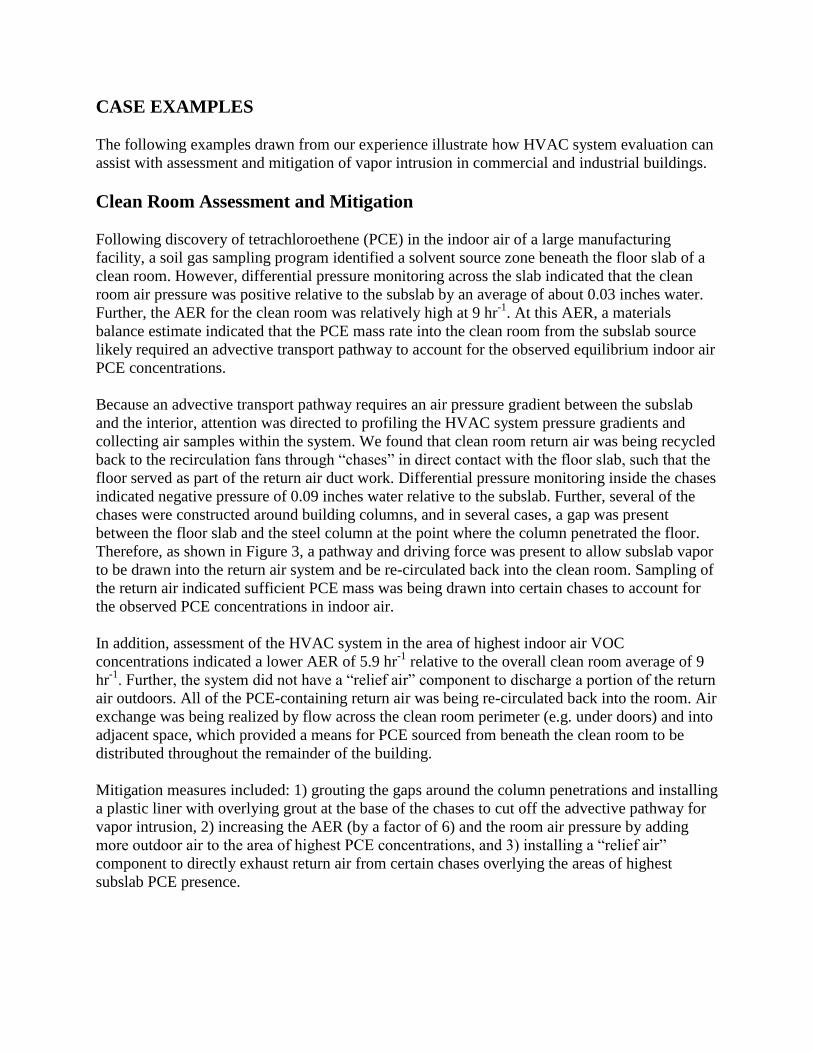
The following examples drawn from our experience illustrate how HVAC system evaluation can
assist with assessment and mitigation of vapor intrusion in commercial and industrial buildings.
Clean Room Assessment and Mitigation
Following discovery of tetrachloroethene (PCE) in the indoor air of a large manufacturing
facility, a soil gas sampling program identified a solvent source zone beneath the floor slab of a
clean room. However, differential pressure monitoring across the slab indicated that the clean
room air pressure was positive relative to the subslab by an average of about 0.03 inches water.
Further, the AER for the clean room was relatively high at 9 hr-1
. At this AER, a materials
balance estimate indicated that the PCE mass rate into the clean room from the subslab source
likely required an advective transport pathway to account for the observed equilibrium indoor air
PCE concentrations.
Because an advective transport pathway requires an air pressure gradient between the subslab
and the interior, attention was directed to profiling the HVAC system pressure gradients and
collecting air samples within the system. We found that clean room return air was being recycled
back to the recirculation fans through “chases” in direct contact with the floor slab, such that the
floor served as part of the return air duct work. Differential pressure monitoring inside the chases
indicated negative pressure of 0.09 inches water relative to the subslab. Further, several of the
chases were constructed around building columns, and in several cases, a gap was present
between the floor slab and the steel column at the point where the column penetrated the floor.
Therefore, as shown in Figure 3, a pathway and driving force was present to allow subslab vapor
to be drawn into the return air system and be re-circulated back into the clean room. Sampling of
the return air indicated sufficient PCE mass was being drawn into certain chases to account for
the observed PCE concentrations in indoor air.
In addition, assessment of the HVAC system in the area of highest indoor air VOC
concentrations indicated a lower AER of 5.9 hr-1
relative to the overall clean room average of 9
hr-1
. Further, the system did not have a “relief air” component to discharge a portion of the return
air outdoors. All of the PCE-containing return air was being re-circulated back into the room. Air
exchange was being realized by flow across the clean room perimeter (e.g. under doors) and into
adjacent space, which provided a means for PCE sourced from beneath the clean room to be
distributed throughout the remainder of the building.
Mitigation measures included: 1) grouting the gaps around the column penetrations and installing
a plastic liner with overlying grout at the base of the chases to cut off the advective pathway for
vapor intrusion, 2) increasing the AER (by a factor of 6) and the room air pressure by adding
more outdoor air to the area of highest PCE concentrations, and 3) installing a “relief air”
component to directly exhaust return air from certain chases overlying the areas of highest
subslab PCE presence.

Figure 3: Depiction of vapor intrusion pathway under clean room HVAC influence
As a result of these measures, the indoor PCE levels decreased by more than a factor of ten,
which was greater than can be attributed to the increase in AER alone and indicates a reduction
in the vapor intrusion rate by cutting off the primary advective pathway and increasing the room
pressure. Sampling of the return air chases indicated remaining PCE concentrations similar to
that within the room, indicating the chases had ceased drawing in PCE mass from the subslab.
Finally, with the substantial reduction of the PCE levels in the clean room, sampling of the
remainder of the building indicated no detections of PCE. Follow-up measures are planned to
address VOC source removal.
This example highlights that so-called “positive pressure” rooms or buildings may not be under
positive pressure conditions everywhere, even in clean rooms specifically designed to be under
positive pressure. It is important to evaluate interior air pressure gradients and flow patterns to
identify points in the HVAC system configuration where air pressure may be lower than in the
occupied space or the subslab. If these areas coincide with areas of subslab VOC presence, the
potential for advection-driven vapor intrusion increases.
Mixed-Use Building Assessment and Mitigation
A subslab soil gas assessment identified VOC presence responsible for PCE levels in indoor air
throughout a large (greater than 300,000 ft2) mixed-use industrial building containing offices,
laboratories, warehouse space, and vacant former manufacturing areas. The assessment revealed
that the highest indoor PCE concentrations coincided with areas where subslab PCE
concentrations were also high, and where AER was found to be relatively low. Interior air
pressure in these areas was also found to be near neutral, or slightly lower (0.005 to 0.01 inches
water) than the air pressure recorded below the floor slab. The pattern of declining indoor PCE
concentrations with distance from the highest indoor and subslab PCE levels suggested
dispersion and mixing of PCE throughout the building by way of HVAC operations, and not by
direct intrusion of VOCs through the slab in all areas.
In the areas where AER was low compared to the rest of the building, specific HVAC
modifications included the following measures intended to increase AER and indoor air pressure:
The economizer on an AHU serving an office area was disabled to eliminate variability in
the outdoor air intake rate and provide a consistent flow and higher AER.
In a storage room without active ventilation, a transfer fan was installed through the wall
between the room and the adjacent hallway to increase AER.
Relief air flow was increased from an AHU in an area of higher indoor VOC
concentration to exhaust more return air and reduce re-circulation of VOC-containing air.
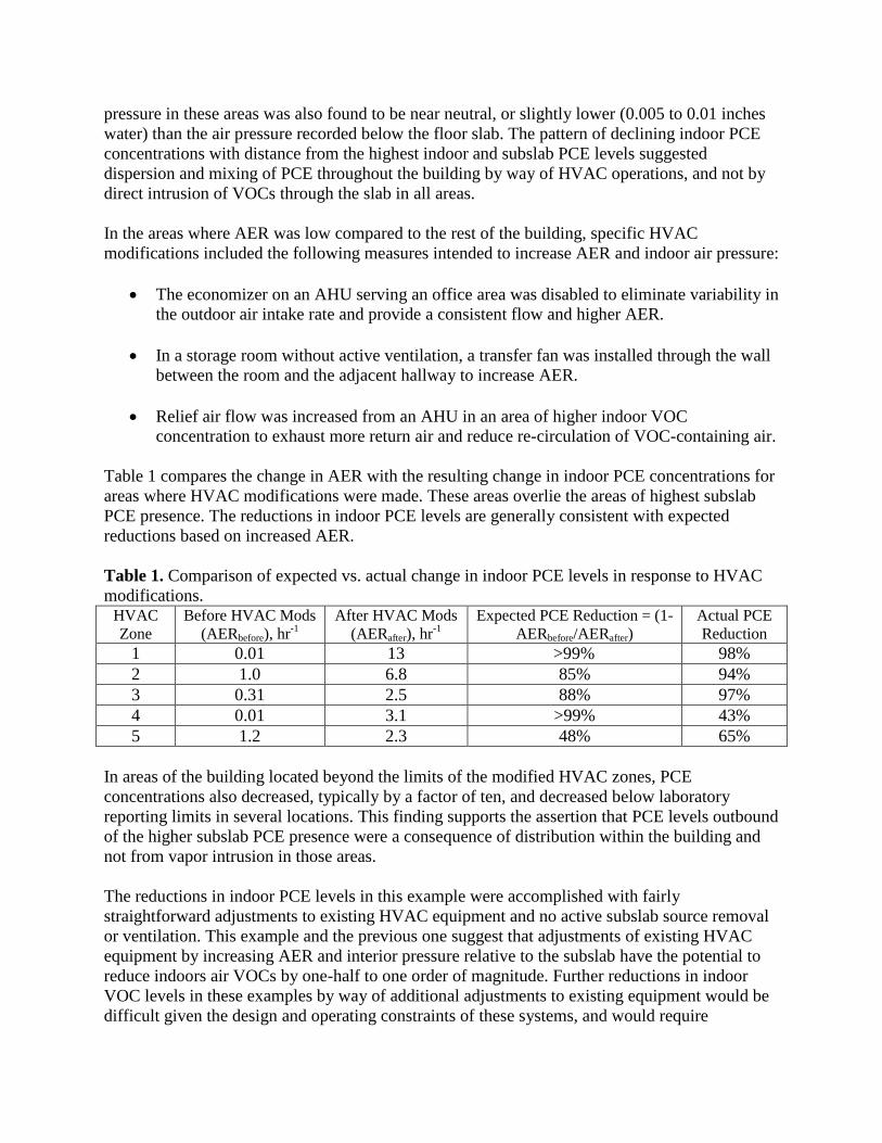
Table 1 compares the change in AER with the resulting change in indoor PCE concentrations for
areas where HVAC modifications were made. These areas overlie the areas of highest subslab
PCE presence. The reductions in indoor PCE levels are generally consistent with expected
reductions based on increased AER.
Table 1. Comparison of expected vs. actual change in indoor PCE levels in response to HVAC
modifications. HVAC
Zone
Before HVAC Mods
(AERbefore), hr-1
After HVAC Mods
(AERafter), hr-1
Expected PCE Reduction = (1-
AERbefore/AERafter)
Actual PCE
Reduction
1 0.01 13 >99% 98%
2 1.0 6.8 85% 94%
3 0.31 2.5 88% 97%
4 0.01 3.1 >99% 43%
5 1.2 2.3 48% 65%
In areas of the building located beyond the limits of the modified HVAC zones, PCE
concentrations also decreased, typically by a factor of ten, and decreased below laboratory
reporting limits in several locations. This finding supports the assertion that PCE levels outbound
of the higher subslab PCE presence were a consequence of distribution within the building and
not from vapor intrusion in those areas.
The reductions in indoor PCE levels in this example were accomplished with fairly
straightforward adjustments to existing HVAC equipment and no active subslab source removal
or ventilation. This example and the previous one suggest that adjustments of existing HVAC
equipment by increasing AER and interior pressure relative to the subslab have the potential to
reduce indoors air VOCs by one-half to one order of magnitude. Further reductions in indoor
VOC levels in these examples by way of additional adjustments to existing equipment would be
difficult given the design and operating constraints of these systems, and would require
investment in new equipment at costs exceeding $100,000. VOC source investigation is planned
to evaluate source removal as potentially more cost effective to achieve further reductions in
indoor air VOC levels.
Fan Room Assessment
In many buildings, the AHUs are installed in mechanical rooms or fan rooms located on the
ground floor. The air pressure within the fan room may be lower than the pressure in the subslab
and the remainder of the building because the fan will potentially draw in room air through
seams and/or leaks in the AHU housing and intake duct work.
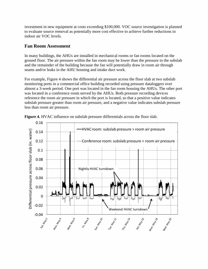
For example, Figure 4 shows the differential air pressure across the floor slab at two subslab
monitoring ports in a commercial office building recorded using pressure dataloggers over
almost a 3-week period. One port was located in the fan room housing the AHUs. The other port
was located in a conference room served by the AHUs. Both pressure recording devices
reference the room air pressure in which the port is located, so that a positive value indicates
subslab pressure greater than room air pressure, and a negative value indicates subslab pressure
less than room air pressure.
Figure 4. HVAC influence on subslab pressure differentials across the floor slab.
-0.04
-0.02
0
0.02
0.04
0.06
0.08
0.1
0.12
0.14
0.16
Dif
fere
nti
al p
ress
ure
acr
oss
flo
or
sla
b (
in. w
ate
r) HVAC room: subslab pressure > room air pressure
Conference room: subslab pressure < room air pressure
Weekend HVAC turndown
Nightly HVAC turndown
The graph highlights the following two HVAC characteristics discussed in this paper that can
influence vapor intrusion potential:
1) A clear pattern of nightly and weekend shutdown of the AHUs is demonstrated, during
which time subslab pressure differentials at both locations converge to near-neutral
conditions, and
2) While the conference room experiences “positive pressure” when the AHUs are operating
(the subslab pressure is less than the room air pressure), the fan room is under negative
pressure (the subslab pressure is greater than the fan room pressure). This condition could
cause pressure gradient-driven vapor intrusion into the fan room, entry of vapors into the
AHU housing, and distribution of VOCs throughout the building. In this case, an
insufficient presence of VOCs below the fan room coupled with the integrity of the floor
slab combined to prevent vapor intrusion, but the pressure gradient was favorable for
vapor intrusion in the absence of these other factors.
Similar to conditions in fan rooms, the operation of exhaust fans in particular spaces may
generate localized areas of lower pressure relative to subslab pressure that can drive vapor
intrusion.
SUMMARY
HVAC system influence on vapor intrusion potential is fundamentally a function of air pressure
gradients and air exchange rates. HVAC systems can exacerbate vapor intrusion when active air
transfer systems, such as return air fans and exhaust fans, create a pressure gradient into the
building proximate to a subslab VOC source. In addition, once VOCs enter a building, the
HVAC system can distribute the contamination far from the source area as a result of internal
mixing and air flow patterns.
Unlike most residential structures, many commercial and industrial HVAC systems are designed
for active air exchange. Given that indoor VOC concentrations vary linearly with air exchange
rate, adjustments to the air exchange rate provides a quantifiably predictive means to improve air
quality independent of VOC source reduction methods. Given HVAC unit cost estimates, HVAC
adjustment costs can be compared with other vapor intrusion mitigation measures, such as VOC
source removal or subslab depressurization.
Two of the case examples presented above suggest that HVAC adjustments to increase AER and
interior air pressure offer the potential to reduce indoor VOC concentrations by about one-half to
one order of magnitude. HVAC adjustments are likely to have practical limits, defined by cost of
new equipment or occupant comfort, which will be building-specific. If greater improvement is
needed then predicted by HVAC adjustments, then consideration should be given to other
mitigation measures.
REFERENCES
1. U.S. Environmental Protection Agency, USEPA’s Vapor Intrusion Database: Preliminary
Evaluation of Attenuation Factors (Draft), March 4, 2008.
2. Eklund, B. and Burrows, D., Prediction of Indoor Air Quality from Soil-Gas Data at
Industrial Buildings, Ground Water Monitoring & Remediation, Vol 29, No. 1, Winter 2009.
3. Berry-Spark, K., McAlary, T., Bice, N., DeFlaun, M., Zeeb P., Villaroman,C., and Ettinger,
R., Risk Management Approaches at Vapor Intrusion Sites - Chlorinated Solvents Case
Studies, Platform presentation at the Fourth International Conference on Remediation of
Chlorinated and Recalcitrant Compounds, Monterey, CA, May 24-27, 2004.
4. McHugh, T., Bailey, D., Landazuri, R., Chadwick, B., Rivera-Duarte, I., Evaluation of Vapor
Intrusion Using Controlled Building Pressure Conditions, Platform presentation at the
Seventh International Conference on Remediation of Chlorinated and Recalcitrant
Compounds, Monterey, CA, May 24, 2010.
5. Bhatia, A., Commercial HVAC, CEDengineering.com, Course No. M08-003 (accessed
January 2010).
6. U. S. Environmental Protection Agency, Indoor Air Vapor Intrusion Mitigation Approaches,
EPA/600/R-08-115, Cincinnati, Ohio, October 2008.
7. Interstate Technology Regulatory Council (ITRC), Vapor Intrusion Pathway: A Practical
Guideline, Washington, D.C., January 2007.
8. American Society of Heating, Refrigerating, and Air-Conditioning Engineers (ASHRAE),
Ventilation for Acceptable Indoor Air Quality, ANSI/ASHRAE Standard 62.1-2004, Atlanta,
GA, 2004.
9. Caulfield, S.M., HVAC Systems and Vapor Intrusion; Northeast Waste Management
Officials’ Association (NEWMOA) and Brown University, Workshop on Vapor Intrusion in
Commercial and Industrial Buildings: Assessment and Mitigation, Westford, MA, September
23, 2008.