HVAC - How to Size and Design Ducts - CED Engineering to Size and Design Ducts.pdf · 15.6...
91
HVAC - How to Size and Design Ducts Course No: M06-032 Credit: 6 PDH A. Bhatia Continuing Education and Development, Inc. 9 Greyridge Farm Court Stony Point, NY 10980 P: (877) 322-5800 F: (877) 322-4774 [email protected]
-
Upload
truongkien -
Category
Documents
-
view
256 -
download
2
Transcript of HVAC - How to Size and Design Ducts - CED Engineering to Size and Design Ducts.pdf · 15.6...
HVAC - How to Size and Design Ducts Course No: M06-032
Credit: 6 PDH
A. Bhatia
Continuing Education and Development, Inc. 9 Greyridge Farm Court Stony Point, NY 10980 P: (877) 322-5800 F: (877) 322-4774 [email protected]
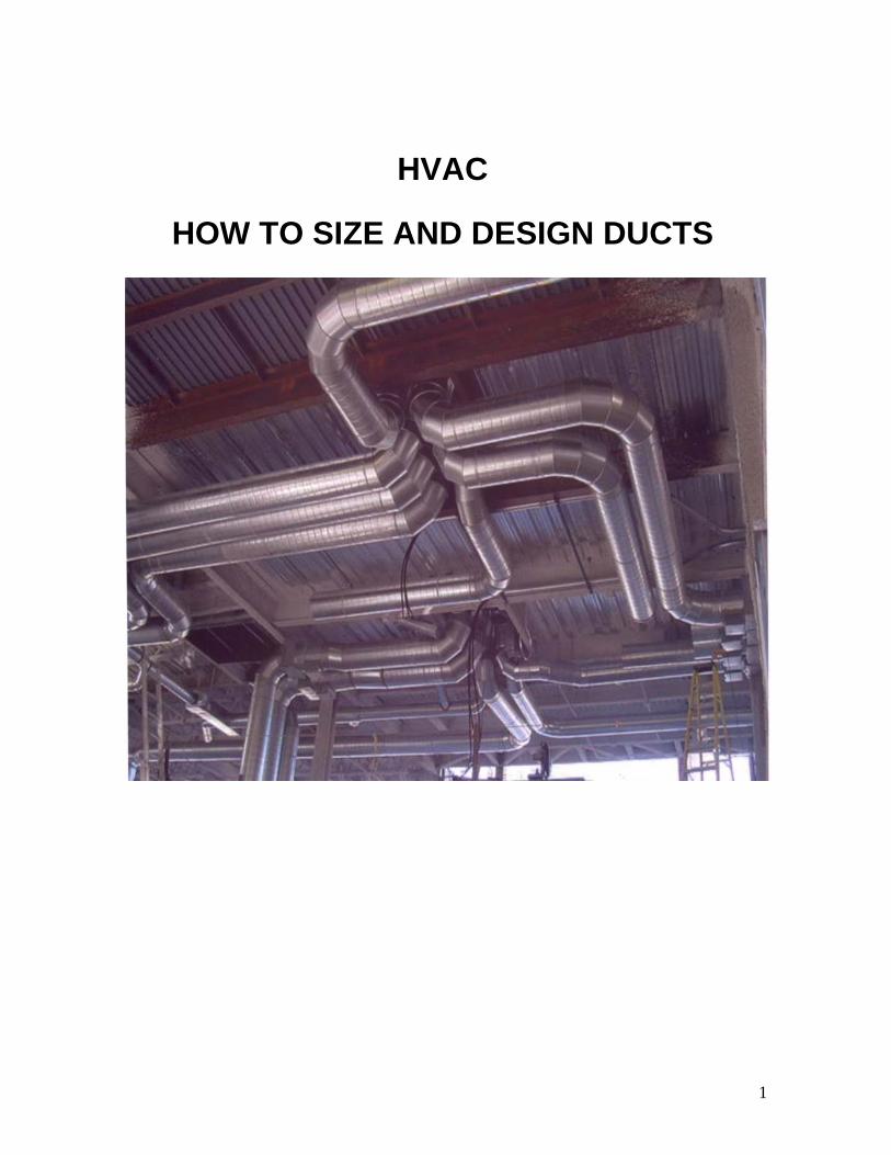
HVAC
HOW TO SIZE AND DESIGN DUCTS
1
CONTENTS
1.0. DUCTWORK DESIGN PRINCIPLES
1.1 Basic Definitions
1.2 Air Flow Principles
1.3 Total Pressure, Velocity Pressure, and Static Pressure
1.4 Air Flow Characteristics in Duct
2.0. DUCT COMPONENTS & MATERIALS
2.1 Duct Components
2.2 Duct Materials
3.0. DUCT CLASSIFICATION
3.1 Velocity Classification
3.2 Pressure classification
3.3 Velocity classification v/s Pressure classification
4.0. DUCT SHAPES
4.1 Round Ducts
4.2 Rectangular Ducts
4.3 Oval Ducts
4.4 Equivalent Diameter
5.0. DUCT SIZING
5.1 Equal friction method
5.2 Velocity Reduction Method
5.3 Static Regain Method
6.0. PRESSURE LOSSES IN AIR DISTRIBUTION SYSTEM
6.1 Duct Friction Losses
6.2 Duct Fitting Dynamic Losses
6.3 The Concept of Duct Equivalent Length
2

6.4 Pressure Loss across Components
7.0. FAN SIZING
7.1 Fan Selection Example
7.2 Balancing Air
7.3 Fan System Effect
8.0. THE SUPPLY DUCT SYSTEM
8.1 Extended Plenum Systems
8.2 Reducing Plenum System
8.3 Reducing Trunk System
8.4 Spider System
8.5 Radial System
8.6 Perimeter Loop System
8.7 Rules of Duct Design (ACCA Manual D – Residential Duct Systems)
9.0. RETURN DUCT SYSTEMS
9.1 Distributed Return
9.2 Central Return
9.3 Pressure Balancing
10.0. DUCT FITTINGS AND TERMINAL UNITS
10.1 Duct Fittings and Transitions
10.2 Volume Control Dampers
10.3 Fire and Smoke Dampers
10.4 Diffusers, Grilles & Registers
10.5 Location of Air Inlets and Outlets
11.0. DUCT CONSTRUCTION & REINFORCEMENT
11.1 Duct Construction
11.2 Duct Sheet Metal Thickness
3
11.3 Aspect Ratio
11.4 Standard Duct Sizes
11.5 Duct Fabrication and Lengths
11.6 Duct Hanger Spacing
12.0. GOOD ENGINEERING PRACTICES
12.1 Energy Conservation
12.2 Good Engineering Practices for Designing Ductwork
13.0. DUCTWORK INSULATION AND SEALING
13.1 Ductwork Insulation
13.2 Ductwork Air Leakage
13.3 Duct Leakage Tests
13.4 Duct Sealing
14.0. DUCT ATTENUATION AND NOISE CONSIDERATIONS
14.1 HVAC Noise Points
14.2 Acoustical Analysis of a Ductwork System
15.0. DUCTWORK TESTING & SYSTEM PERFORMANCE
15.1 Balancing the System
15.2 Testing Methods and Equipment
15.3 Air Flow Measurement Instruments
15.4 Determining Air Flow at Grilles
15.5 Determining Air Flow in Ducts
15.6 Provisions during Design for Testing, Adjusting, and Balancing
16.0. DUCT CLEANING
16.1 Duct Cleaning Methods
16.2 Coordination between Design Specialties
4

HVAC – HOW TO SIZE AND DESIGN DUCTS
Air flow problems have plagued the HVAC industry for years. No matter how much money
you spend on a high-quality HVAC system, the equipment won’t work at its best without
properly designed and installed ductwork. Ducts that are not well designed result in
discomfort, high energy costs, bad air quality, and increased noise levels.
A well-designed ductwork system should deliver maximum interior comfort at the lowest
operating cost while also preserving indoor air quality. The chief requirements of an air
conditioning duct system are:
1. It should convey specified rates of air flow to prescribed locations.
2. It should be economical in combined initial cost, fan operating cost and cost of
building space.
3. It should not transmit or generate objectionable noise.
A primary issue is the tradeoff between the initial cost of the duct system and the energy cost
of the air distribution system. Larger ducts require a larger initial investment, but result in
lower fan energy costs over the life of the system. Other issues include space restrictions,
noise level, capacity for expansion, appearance, etc.
This course will discuss the basic fundamentals and principles of air conditioning duct design
and layout.
1.0. DUCTWORK DESIGN PRINCIPLES
Starting with the basics, let's start at the most elementary level of air flow
fundamentals.
1.1 Basic Definitions
The following basic terminology is extensively used in this course.
• cfm: volume of air flow; cubic feet/minute
• fpm: velocity or speed of air flow; feet/minute
• sq.ft: duct size or cross-sectional area; square feet
Air volume in cfm can be calculated by multiplying the air velocity by the cross-sectional
area of the duct in square feet.
5
• cfm = fpm x Area
Given any two of these three quantities, the third can be readily determined:
• fpm = cfm/area
• Area = cfm/fpm
Gauge and Absolute Pressures:
Gauge pressure is indicated on the gauge; absolute pressure is the total of the indicated
gauge pressure plus atmospheric pressure. The general equation for absolute pressure
is:
Gauge pressure + atmospheric pressure = absolute pressure
For example, if the gauge reads 10 psig then, using the above equation, the absolute
pressure would be 24. 7 psia:
10 psig + 14.7 psi = 24.7 psia
Ordinary heating, ventilating, and air conditioning duct systems read air pressures at 0.4
psi or less, often much less. 1 psi equals 27.7 inches of water gauge; a common duct
pressure of 0.25 inches water column is equal to (0.25 divided by 27.7 in-wc/psi) = 0.009
psi.
Duct Pressure:
Duct system is pressurized by three pressures:
• Static pressure: It is the air pressure in the duct, which is used for fan selection.
• Velocity pressure: It is the pressure generated by the velocity and weight of the
air, which is used for measuring the flow (cfm) in a system.
• Total pressure: It is used to find velocity pressure. Static pressure plus velocity
pressure equals total pressure.
Pressure in the ductwork is measured in inches of water column (in-wc).
Standard Air Density:
Air has mass. Standard air has a density of 0.075 lbs/ ft3.
System capacity is directly affected by changes in air flow. As air is heated or humidified,
its specific volume increases and its density decreases. If the air density is low, more
6
cfm is required to keep the mass flow rate the same. If air density is not considered,
many systems will have very low air flow.
Correction for the density is however not needed in air conditioning or cooling
applications, if the temperature is between 40°F to 100°F and up to 1000 ft. in
elevation.
Fan Capacity:
The volume of air will not be affected in a given system because a fan will move the
same amount of air regardless of the air density. In other words, if a fan will move 3,000
cfm at 70°F, it will also move 3,000 cfm at 250°F
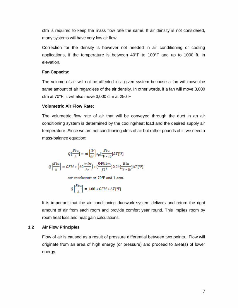
Volumetric Air Flow Rate:
The volumetric flow rate of air that will be conveyed through the duct in an air
conditioning system is determined by the cooling/heat load and the desired supply air
temperature. Since we are not conditioning cfms of air but rather pounds of it, we need a
mass-balance equation:
It is important that the air conditioning ductwork system delivers and return the right
amount of air from each room and provide comfort year round. This implies room by
room heat loss and heat gain calculations.
1.2 Air Flow Principles
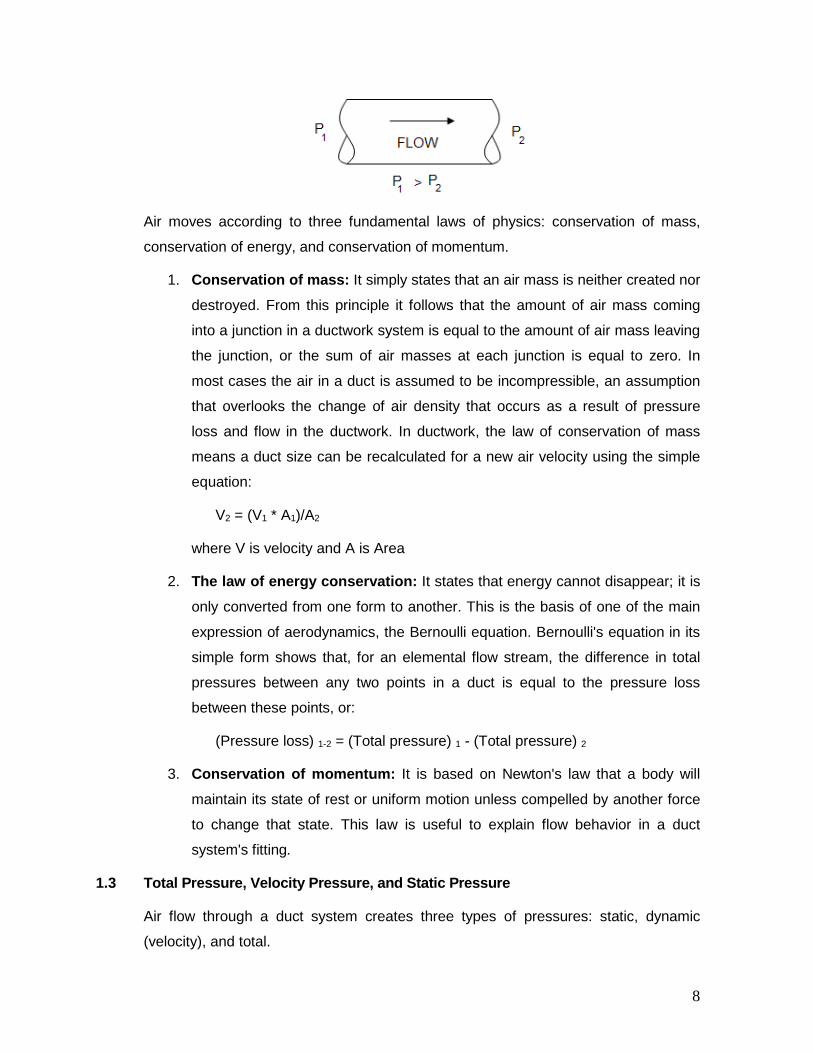
Flow of air is caused as a result of pressure differential between two points. Flow will
originate from an area of high energy (or pressure) and proceed to area(s) of lower
energy.
7
Air moves according to three fundamental laws of physics: conservation of mass,
conservation of energy, and conservation of momentum.
1. Conservation of mass: It simply states that an air mass is neither created nor
destroyed. From this principle it follows that the amount of air mass coming
into a junction in a ductwork system is equal to the amount of air mass leaving
the junction, or the sum of air masses at each junction is equal to zero. In
most cases the air in a duct is assumed to be incompressible, an assumption
that overlooks the change of air density that occurs as a result of pressure
loss and flow in the ductwork. In ductwork, the law of conservation of mass
means a duct size can be recalculated for a new air velocity using the simple
equation:
V2 = (V1 * A1)/A2
where V is velocity and A is Area
2. The law of energy conservation: It states that energy cannot disappear; it is
only converted from one form to another. This is the basis of one of the main
expression of aerodynamics, the Bernoulli equation. Bernoulli's equation in its
simple form shows that, for an elemental flow stream, the difference in total
pressures between any two points in a duct is equal to the pressure loss
between these points, or:
(Pressure loss) 1-2 = (Total pressure) 1 - (Total pressure) 2
3. Conservation of momentum: It is based on Newton's law that a body will
maintain its state of rest or uniform motion unless compelled by another force
to change that state. This law is useful to explain flow behavior in a duct
system's fitting.
1.3 Total Pressure, Velocity Pressure, and Static Pressure
Air flow through a duct system creates three types of pressures: static, dynamic
(velocity), and total.
8
1. Static pressure: Static Pressure is the pressure that causes air in the duct to
flow. Static pressure is the outward push of air against duct surfaces and is a
measure of resistance when air moves through an object like duct work.
Measured in inches of water column (in-wc), it acts equally in all directions and
is independent of velocity.
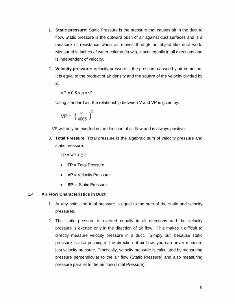
2. Velocity pressure: Velocity pressure is the pressure caused by air in motion.
It is equal to the product of air density and the square of the velocity divided by
2.
VP = 0.5 x ρ x v2
Using standard air, the relationship between V and VP is given by:
VP will only be exerted in the direction of air flow and is always positive.
3. Total Pressure: Total pressure is the algebraic sum of velocity pressure and
static pressure.
TP = VP + SP
• TP = Total Pressure
• VP = Velocity Pressure
• SP = Static Pressure
1.4 Air Flow Characteristics in Duct
1. At any point, the total pressure is equal to the sum of the static and velocity
pressures.
2. The static pressure is exerted equally in all directions and the velocity
pressure is exerted only in the direction of air flow. This makes it difficult to
directly measure velocity pressure in a duct. Simply put, because static
pressure is also pushing in the direction of air flow, you can never measure
just velocity pressure. Practically, velocity pressure is calculated by measuring
pressure perpendicular to the air flow (Static Pressure) and also measuring
pressure parallel to the air flow (Total Pressure).
9
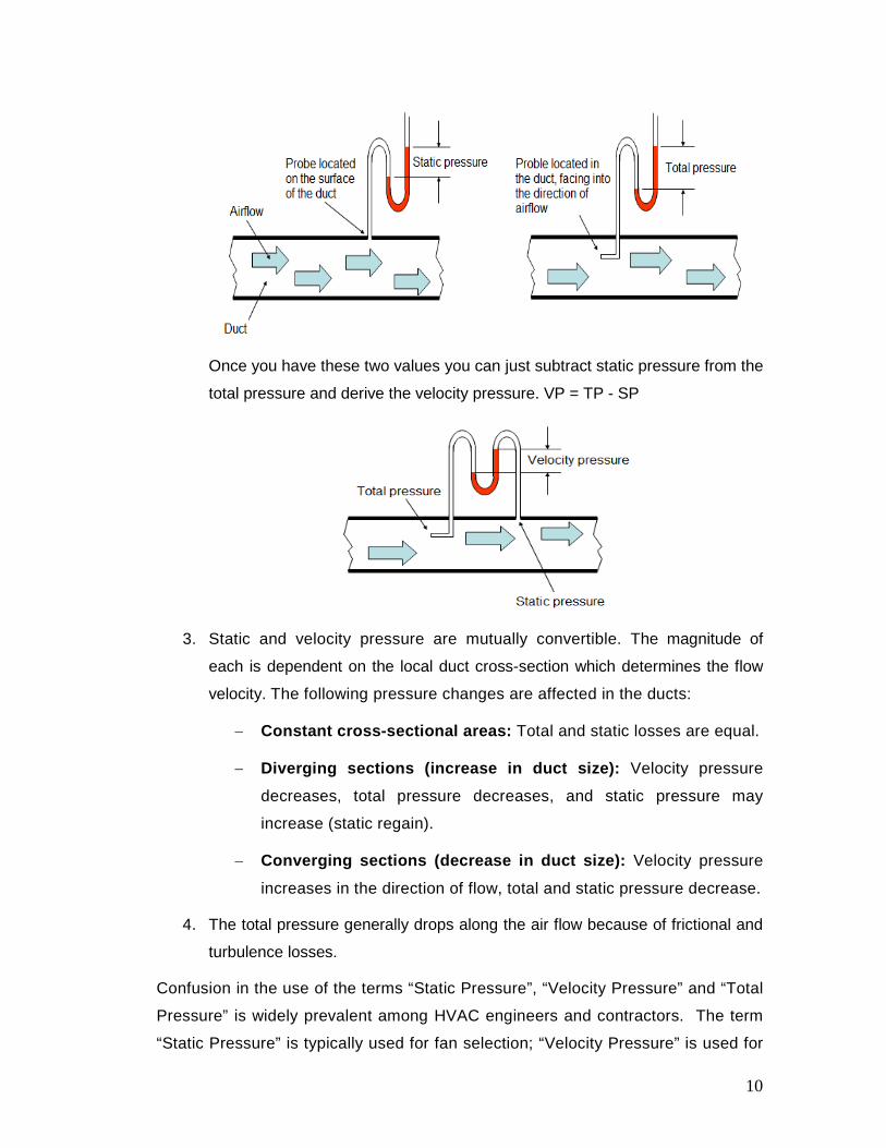
Once you have these two values you can just subtract static pressure from the
total pressure and derive the velocity pressure. VP = TP - SP
3. Static and velocity pressure are mutually convertible. The magnitude of
each is dependent on the local duct cross-section which determines the flow
velocity. The following pressure changes are affected in the ducts:
− Constant cross-sectional areas: Total and static losses are equal.
− Diverging sections (increase in duct size): Velocity pressure
decreases, total pressure decreases, and static pressure may
increase (static regain).
− Converging sections (decrease in duct size): Velocity pressure
increases in the direction of flow, total and static pressure decrease.
4. The total pressure generally drops along the air flow because of frictional and
turbulence losses.
Confusion in the use of the terms “Static Pressure”, “Velocity Pressure” and “Total
Pressure” is widely prevalent among HVAC engineers and contractors. The term
“Static Pressure” is typically used for fan selection; “Velocity Pressure” is used for
10
measuring cfm in a system, and “Total Pressure” is used to find the velocity
pressure. Total Pressure determines the actual mechanical energy that must be
supplied to the system.
2.0. DUCT COMPONENTS & MATERIALS
The air distribution system will have a designation depending on the function
of the duct. Broadly, there are five designations of ducts:
1. Supply air ductwork supplies conditioned air from the air handling unit to
the conditioned area.
2. Return air ductwork removes air from the conditioned building spaces
and returns the air to the air handling unit, which reconditions the air. In
some cases, part of the return air in this ductwork is exhausted to the
building exterior.
3. Fresh air ductwork supplies outdoor air to the air handling unit. Outdoor
air is used for ventilating the occupied building space.
4. Exhaust (relief) air ductwork carries and discharges air to the outdoors.
Exhaust air is taken from toilets, kitchen, laboratories and other areas
requiring ventilation.
5. Mixed air ductwork mixes air from the outdoor air and the return air then
supplies this mixed air to the air handling unit.
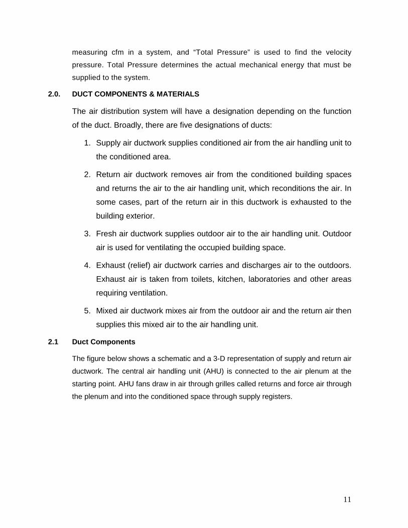
2.1 Duct Components
The figure below shows a schematic and a 3-D representation of supply and return air
ductwork. The central air handling unit (AHU) is connected to the air plenum at the
starting point. AHU fans draw in air through grilles called returns and force air through
the plenum and into the conditioned space through supply registers.
11

The duct components are as follows:
Plenum or Main Trunk: The plenum is the main part of the supply and return
duct system that goes directly from the air handler to the “Trunk Duct”.
12

Trunk Duct: A duct that is split into more than one duct is called a “trunk”, just
like a tree. Ducts that are on the end of a trunk and terminate in a register are
called branches.
Take Off: Branch ducts are fastened to the main trunk by a takeoff-fitting. The
takeoff encourages the air moving the duct to enter the takeoff to the branch duct.
Air Terminals Devices: Air terminals are the supply air outlets and return or
exhaust air inlets. For supply, diffusers are most common, but grilles and
registers are also used widely. A diffuser is an outlet device discharging supply
air in a direction radially to the axis of entry. A register is a grille equipped with
a volume control damper. A grille is without a damper.
2.2 Duct Materials
Ducting is generally formed by folding sheet metal into the desired shape.
Traditionally, air conditioning ductwork is made of galvanized steel, next in
popularity is aluminum. Other metals used under special circumstances are
copper and stainless steel. Metals that are used extensively depend on the
application of the duct and are listed below:
1. Galvanized Steel: It is a standard, most common material used in
fabricating ductwork for most comfort air conditioning systems. The
specifications for galvanized steel sheet are ASTM A653, coating G90.
2. Aluminium: It is widely used in clean room applications. These are also
preferred systems for moisture laden air, special exhaust systems and
ornamental duct systems. The specifications for Aluminium sheet are
ASTM B209, alloy 1100, 3003 or 5052.
3. Stainless Steel: It is used in duct systems for kitchen exhaust, moisture
laden air, and fume exhaust. The specifications for stainless steel sheet are
ASTM A167, Class 302 or 304, Condition A (annealed) Finish No. 4 for
exposed ducts and Finish No. 2B for concealed duct.
4. Carbon Steel (Black Iron): It is widely used in applications involving flues,
stacks, hoods, other high temperature and special coating requirements for
industrial use.
5. Copper: It is mainly used for certain chemical exhaust and ornamental
ductwork.
13
Pressure in the air conditioning ducts is small, so materials with a great deal of
strength are not needed. The thickness of the material depends on the dimensions
of the duct, the length of the individual sections, and the cross-sectional area of
the duct.
Non-Metallic ducts
This category includes ducts made from plastic or foam boards, shaped by cutting
and folded to produce the required cross-sectional geometry. Boards are faced
usually with an aluminum coating, both internal and external.
The main drawback of this type of ducting is its fire classification. Even if it complies
with local standards, when exposed to fire, it often exhibits poor performance in terms
of the production of both smoke and flaming droplets.
1. Fibreglass Reinforced Plastic (FRP): It is used mainly for chemical
exhaust, scrubbers, and underground duct systems. Advantages are
resistance to corrosion, self-insulation, excellent sound attenuation and
high quality sealing. Limiting characteristics include cost, weight, range of
chemical and physical properties, and code acceptance.
2. Polyvinyl Chloride (PVC): It is used for exhaust systems for chemical
fumes and underground duct systems. Advantages include resistance to
corrosion, light weight, and ease of modification. Limiting characteristics
include cost, fabrication, code acceptance, thermal shock, and weight.
3. Fabric: Fabric ducting, also known as textile ducts, is usually made of
special permeable polyester material and is normally used where even air
distribution is essential. Due to the nature or the air distribution, textile
ducts are not usually concealed within false ceilings. Condensation is not a
concern with fabric ducts and therefore these can be used where air is to
be supplied below the dew point without insulation.
4. Flex Duct: Flex ducts consist of a duct inner liner supported on the inside
by a helix wire coil and covered by blanket insulation with a flexible vapor
barrier jacket on the outside. Flex ducts are often used for runouts, as well
as with metal collars used to connect the flexible ducts to supply plenums,
trunks and branches constructed from sheet metal or duct board. Flex
ducts provide convenience of installation as these can be easily adapted to
14

avoid clashes but has certain disadvantages. These have more friction loss
inside them than metal ducting. Flex duct runs should be as short as
possible (5 to 6 ft. max.) and should be stretched as tight as possible.
3.0. DUCT CLASSIFICATION
Ducts are classified in terms of velocity and pressure.
3.1 Velocity Classification
Ducts are classified into 3 basic categories:
1. Low Velocity Systems: They are characterized by air velocities up to
2000 fpm.
2. Medium Velocity Systems: They are characterized by air velocities in the
range of 2,000 to 2,500 fpm.
3. High Velocity Systems: They are characterized by air velocities greater
than 2,500 fpm.
The low velocity system is used in most air conditioning installations because it is
quieter, has lower friction losses, lower fan power, and lower air leakage.
High duct velocities result in lower initial costs but require increased fan static
pressures; therefore, resulting in increased operating costs. Often these need
additional noise attenuation (use of noise silencers) and are not suitable for comfort
applications.
Generally, high-velocity systems are applicable to large multi-story buildings, primarily
because the advantage of savings in duct shafts and floor-to-floor heights is more
substantial. Small two- and three-story buildings are normally low velocity. A velocity
of 1,000 to 1,500 fpm for main ducts and a velocity of 700 to 1,000 fpm for the branch
take offs are recommended.
3.2 Pressure Classification
Duct systems are also divided into three pressure classifications, matching the way
supply fans are classified.
1. Low Pressure: The term low-pressure applies to systems with fan static
pressures less than 3 inches WC. Generally, duct velocities are less than
1,500 fpm.
15
2. Medium Pressure: The term medium pressure applies to systems with fan
static pressures between 3 to 6 inches WC. Generally, duct velocities are
less than or equal to 2,500 fpm.
3. High Pressure: The term high pressure applies to systems with fan static
pressures between 6 to 10 inches WC. Usually the static pressure is limited
to a maximum of 7 inches WC, and duct velocities are limited to 4,000 fpm.
Systems requiring pressures more than 7 inches WC are normally
unwarranted and could result in very high operating costs.
General good engineering practices are:
1. Use of medium pressure classification for primary air ductwork (fan
connections, risers, and main distribution ducts).
2. Use of low pressure classification for secondary air ductwork (run-
outs/branches from main to terminal boxes and distribution devices).
3.3 Velocity Classification vs. Pressure Classification
1. Duct pressure classification influences the duct strength, deflection and air
leakage.
2. Duct velocity classification influences noise, vibration, friction losses and fan
power.
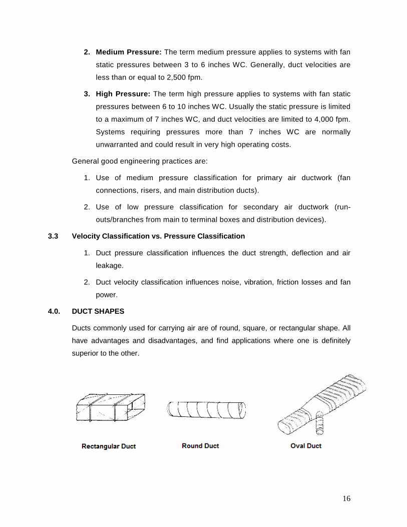
4.0. DUCT SHAPES
Ducts commonly used for carrying air are of round, square, or rectangular shape. All
have advantages and disadvantages, and find applications where one is definitely
superior to the other.
16

4.1 Round Ducts
The duct shape that is the most efficient (offers the least resistance) in conveying
moving air is a round duct, because it has the greatest cross-sectional area and a
minimum contact surface. In other words, it uses less material compared to square or
rectangular ducts for the same volume of air handled.
An 18 inch diameter duct, for example, has the same air-carrying capacity as a 26” x
11” rectangular duct. The round duct has a cross-sectional area of 254.5 sq.-in and a
perimeter of 4.7 ft., while the rectangular duct has a 286 sq.-in area and a perimeter
of 6.2 ft. The rectangular duct thus has 32% more metal in it and would cost
proportionately more. Also the insulation, supports and labor are higher for
rectangular ducts of similar capacity.
Some of the advantages of round ductwork include:
• Round shape results in lower pressure drops, thereby requiring less fan
horsepower to move the air and, consequently, smaller equipment.
• Round shape also has less surface area and requires less insulation when
externally wrapped.
• Round ducts are available in longer lengths than rectangular ducts, thereby
eliminating costly field joints. Spiral lock-seams add rigidity; therefore, spiral
ducts can be fabricated using lighter gauges than longitudinal seam ducts. Spiral ducts leak less and can be more easily sealed compared to rectangular
ducts.
• The acoustic performance of round and oval ducts is superior because their
curved surfaces allow less breakout noise. The low-frequency sound is well
contained in round ducts.
• Round ducts can help promote healthier indoor environments. Less surface
area, no corners and better air flow reduce the chance of dirt and grime
accumulating inside the duct and, therefore, becoming a breeding ground for
bacterial growth.
While round air ducts have great advantages, there are some disadvantages to them.
One of the most notable drawbacks of round air ducts is that they need more clear
height for installation. If the net clear height of a furred space above a suspended
17
ceiling is 14 inches, an 18-in diameter duct cannot be installed therein; however, its
equivalent 26” x 11” rectangular duct will fit the space easily. A combination of a
rectangular plenum and round branches sometimes is a good compromise.
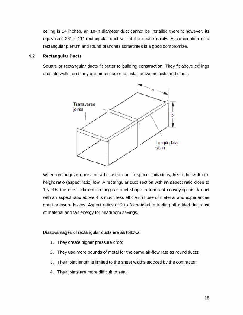
4.2 Rectangular Ducts
Square or rectangular ducts fit better to building construction. They fit above ceilings
and into walls, and they are much easier to install between joists and studs.
When rectangular ducts must be used due to space limitations, keep the width-to-
height ratio (aspect ratio) low. A rectangular duct section with an aspect ratio close to
1 yields the most efficient rectangular duct shape in terms of conveying air. A duct
with an aspect ratio above 4 is much less efficient in use of material and experiences
great pressure losses. Aspect ratios of 2 to 3 are ideal in trading off added duct cost
of material and fan energy for headroom savings.
Disadvantages of rectangular ducts are as follows:
1. They create higher pressure drop;
2. They use more pounds of metal for the same air-flow rate as round ducts;
3. Their joint length is limited to the sheet widths stocked by the contractor;
4. Their joints are more difficult to seal;
18

5. Those with high aspect ratio can transmit excessive noise if not properly
supported.
4.3 Oval Ducts
Flat oval ducts have smaller height requirements than round ducts and retain most of
the advantages of the round ducts. However, fittings for flat oval ducts are difficult to
fabricate or modify in the field. Other disadvantages include:
1. Difficulty of handling and shipping larger sizes;
2. Tendency of these ducts to become more round under pressure; and,
3. In large aspect ratios, difficulties of assembling oval slip joints.
4.4 Equivalent Diameter
Since both round and rectangular ducts are extensively used in air conditioning
systems, it is quite possible that a contractor may wish to substitute one for the other
while working on new construction or modifying an existing system. With this
likelihood, there is the general tendency to substitute cross-sectional areas of round
and rectangular ducts. This is improper and will affect air distribution system
performance. Therefore, it is necessary for the HVAC designer to fully understand
the conditions under which round and rectangular ducts can be interchanged. The
important thing is the duct pressure drop and that’s where the concept of “equivalent
diameter” comes into picture.
By definition, equivalent diameter (Deq) is the diameter of a circular duct that will give
the same pressure drop at the same air flow as the rectangular duct.
From ASHRAE Fundamentals Handbook, the following equations may be used to
convert rectangular and flat oval ducts to and from round.
19
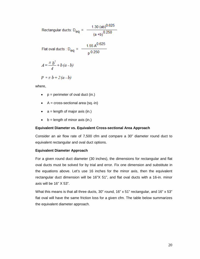
where,
• p = perimeter of oval duct (in.)
• A = cross-sectional area (sq.-in)
• a = length of major axis (in.)
• b = length of minor axis (in.)
Equivalent Diameter vs. Equivalent Cross-sectional Area Approach
Consider an air flow rate of 7,500 cfm and compare a 30” diameter round duct to
equivalent rectangular and oval duct options.
Equivalent Diameter Approach
For a given round duct diameter (30 inches), the dimensions for rectangular and flat
oval ducts must be solved for by trial and error. Fix one dimension and substitute in
the equations above. Let’s use 16 inches for the minor axis, then the equivalent
rectangular duct dimension will be 16”X 51”, and flat oval ducts with a 16-in. minor
axis will be 16” X 53”.
What this means is that all three ducts, 30” round, 16” x 51” rectangular, and 16” x 53”
flat oval will have the same friction loss for a given cfm. The table below summarizes
the equivalent diameter approach.
20
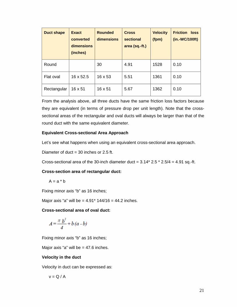
Duct shape Exact converted dimensions (inches)
Rounded dimensions
Cross sectional area (sq.-ft.)
Velocity (fpm)
Friction loss (in.-WC/100ft)
Round 30 4.91 1528 0.10
Flat oval 16 x 52.5 16 x 53 5.51 1361 0.10
Rectangular 16 x 51 16 x 51 5.67 1362 0.10
From the analysis above, all three ducts have the same friction loss factors because
they are equivalent (in terms of pressure drop per unit length). Note that the cross-
sectional areas of the rectangular and oval ducts will always be larger than that of the
round duct with the same equivalent diameter.
Equivalent Cross-sectional Area Approach
Let’s see what happens when using an equivalent cross-sectional area approach.
Diameter of duct = 30 inches or 2.5 ft.
Cross-sectional area of the 30-inch diameter duct = 3.14* 2.5 * 2.5/4 = 4.91 sq.-ft.
Cross-section area of rectangular duct:
A = a * b
Fixing minor axis “b” as 16 inches;
Major axis “a” will be = 4.91* 144/16 = 44.2 inches.
Cross-sectional area of oval duct:
Fixing minor axis “b” as 16 inches;
Major axis “a” will be = 47.6 inches.
Velocity in the duct
Velocity in duct can be expressed as:
v = Q / A
21
where,
• v = air velocity in feet per minute, (fpm)
• Q = air flow through duct in cubic feet per minute, (cfm)
• A = cross-section of duct in square feet, (sq.-ft.)
Friction loss is estimated from the duct friction charts for a given air flow rate and
velocity (refer to the “duct sizing” section below for details).
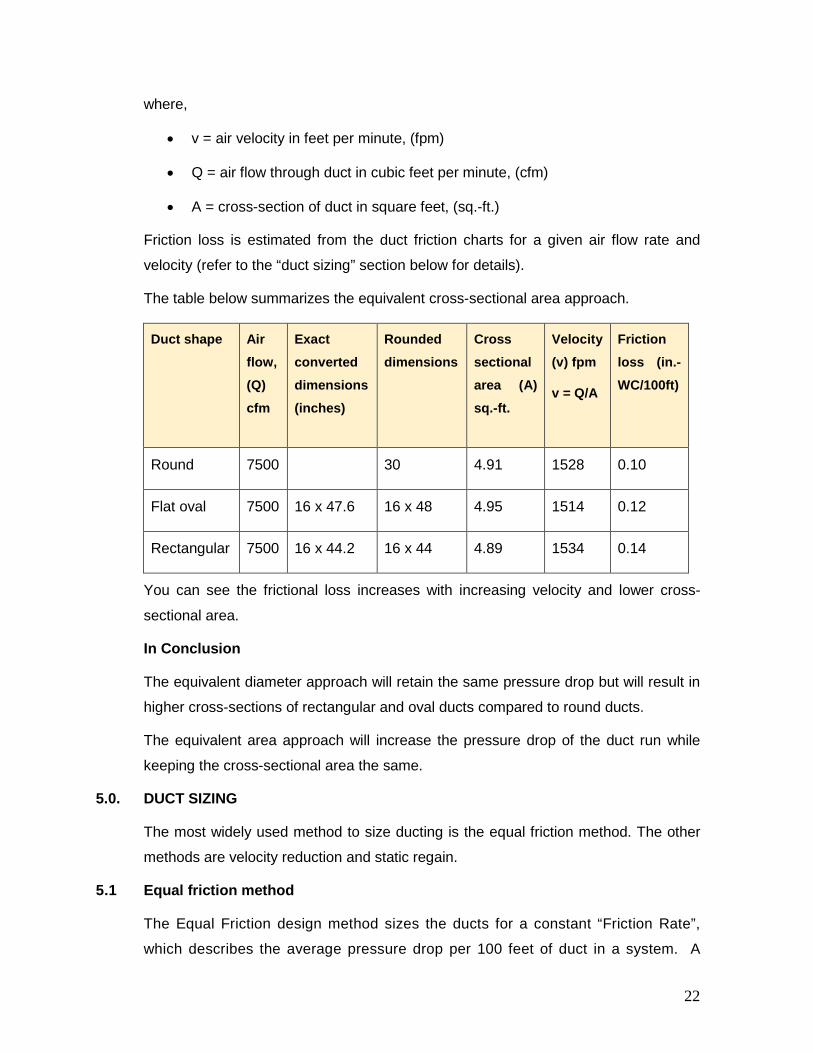
The table below summarizes the equivalent cross-sectional area approach.
Duct shape Air flow, (Q) cfm
Exact converted dimensions (inches)
Rounded dimensions
Cross sectional area (A) sq.-ft.
Velocity (v) fpm
v = Q/A
Friction loss (in.-WC/100ft)
Round 7500 30 4.91 1528 0.10
Flat oval 7500 16 x 47.6 16 x 48 4.95 1514 0.12
Rectangular 7500 16 x 44.2 16 x 44 4.89 1534 0.14
You can see the frictional loss increases with increasing velocity and lower cross-
sectional area.
In Conclusion
The equivalent diameter approach will retain the same pressure drop but will result in
higher cross-sections of rectangular and oval ducts compared to round ducts.
The equivalent area approach will increase the pressure drop of the duct run while
keeping the cross-sectional area the same.
5.0. DUCT SIZING
The most widely used method to size ducting is the equal friction method. The other
methods are velocity reduction and static regain.
5.1 Equal friction method
The Equal Friction design method sizes the ducts for a constant “Friction Rate”,
which describes the average pressure drop per 100 feet of duct in a system. A
22
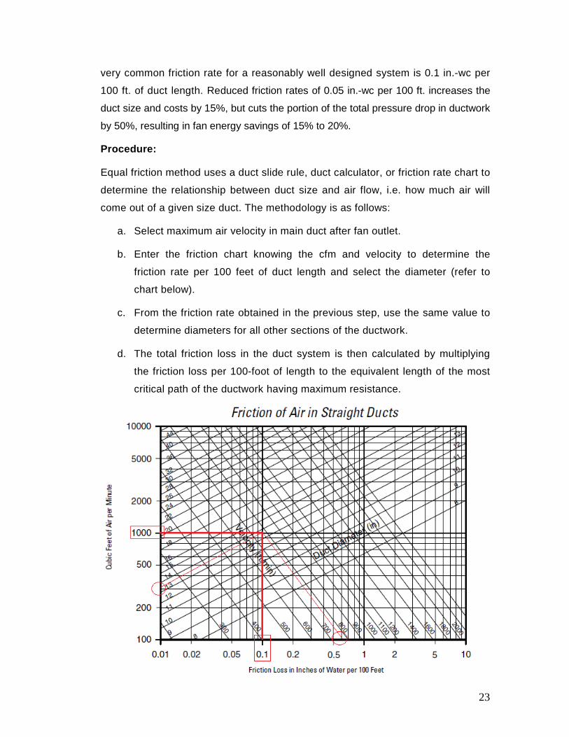
very common friction rate for a reasonably well designed system is 0.1 in.-wc per
100 ft. of duct length. Reduced friction rates of 0.05 in.-wc per 100 ft. increases the
duct size and costs by 15%, but cuts the portion of the total pressure drop in ductwork
by 50%, resulting in fan energy savings of 15% to 20%.
Procedure:
Equal friction method uses a duct slide rule, duct calculator, or friction rate chart to
determine the relationship between duct size and air flow, i.e. how much air will
come out of a given size duct. The methodology is as follows:
a. Select maximum air velocity in main duct after fan outlet.
b. Enter the friction chart knowing the cfm and velocity to determine the
friction rate per 100 feet of duct length and select the diameter (refer to
chart below).
c. From the friction rate obtained in the previous step, use the same value to
determine diameters for all other sections of the ductwork.
d. The total friction loss in the duct system is then calculated by multiplying
the friction loss per 100-foot of length to the equivalent length of the most
critical path of the ductwork having maximum resistance.
23

Example
Determine the diameter and the velocity of air through a duct carrying 1,000 cfm of
air. Assume a friction loss of 0.1 in.-wc per 100 ft. of duct length. Determine the
real pressure drop and velocity on the selected duct size.
Solution:
From the above monograph, the 0.1 in.-wc per 100 ft. friction line intersects the
1,000 cfm line at a round duct diameter of 13.5 inch. Select the next available
round duct size of 14”. When this duct is used, the pressure loss will be 0.09 in.-
wc/100’, and the velocity is ~800 fpm. (Note: the chart illustrated above is only for
educational purpose and may be out of scale.)
There are a variety of commercially available duct calculator tools (also known as
ductulators) that are easy and accurate to use for sizing ducts if you know the flow
rate and friction loss or velocity. Use the following friction loss guidelines for sizing
ducts with a duct calculator tool.
System Type Friction Loss per 100 Feet of Duct (inch water column)
Supply run-outs 0.08
Supply trunk or plenum 0.05
Return ducts 0.02
Advantages of the Equal Friction Method:
1. The method is straightforward and simple.
2. It automatically reduces air velocities in the direction of air flow, which in
turn reduces the potential air flow generated noise.
3. It is the most appropriate method for constant air volume (CAV) systems.
Limitations of the Equal Friction Method:
1. There is no equalization of pressure drops in duct branches unless the system
has a symmetrical layout. Balancing dampers must be installed to balance the
system.
24
2. It is not recommended for VAV systems. If used for VAV supply duct
design, the terminal units require pressure independent (Pi) control
capability to avoid excessive flow rates when duct pressure is high.
3. It is not flexible and adaptable to future layout changes.
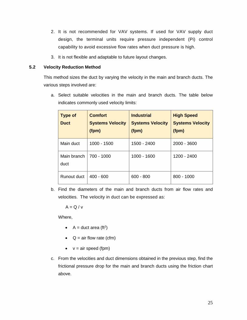
5.2 Velocity Reduction Method
This method sizes the duct by varying the velocity in the main and branch ducts. The
various steps involved are:
a. Select suitable velocities in the main and branch ducts. The table below
indicates commonly used velocity limits:
Type of Duct
Comfort Systems Velocity (fpm)
Industrial Systems Velocity (fpm)
High Speed Systems Velocity (fpm)
Main duct 1000 - 1500 1500 - 2400 2000 - 3600
Main branch
duct
700 - 1000 1000 - 1600 1200 - 2400
Runout duct 400 - 600 600 - 800 800 - 1000
b. Find the diameters of the main and branch ducts from air flow rates and
velocities. The velocity in duct can be expressed as:
A = Q / v
Where,
• A = duct area (ft2)
• Q = air flow rate (cfm)
• v = air speed (fpm)
c. From the velocities and duct dimensions obtained in the previous step, find the
frictional pressure drop for the main and branch ducts using the friction chart
above.
25

5.3 Static Regain Method
Static regain is the process of converting velocity pressure (VP) to static pressure
(SP). We learnt in previous sections that the total pressure (TP) in a duct system is
equal to the sum of the static pressure and velocity pressure (TP = SP + VP).
Therefore, for a given TP, if the VP is high (usually because the duct area is small),
then the static pressure (SP) must be low. SP is the pressure that causes the air in
the duct to flow, and VP is the pressure that results from the air movement. This
means that it is desirable to have a high value of static pressure (SP) compared to the
total pressure (TP) developed by the fan.
The Static Regain method of duct sizing is based on Bernoulli's equation, which
states that when a reduction of velocities takes place, a conversion of velocity
pressure into static pressure occurs. With this method, the duct velocities are
systematically reduced over the length of the distribution layout, which allows the
velocity pressure to convert to static pressure, offsetting friction losses in the
succeeding section of duct. This means there is the same static pressure near all the
branches and all the diffusers and, therefore, the system design requires little or no
balancing.
Advantages:
1. All duct sections have uniform static pressure at all branches and outlets,
thereby simplifying outlet selection and correct air quantity at each outlet.
2. The duct system will stay in balance because the losses and gains are
proportional to a function of the velocities. Therefore, it is an excellent method
for designing variable air volume systems.
3. The Static Regain method uses less pounds of sheet metal and is less noisy.
Disadvantages:
1. One disadvantage might be seen in networks with a large pressure drop in a
section near the fan outlet. The velocity could be reduced to the minimum
within a few sections in such a way that all the ductwork downstream would be
sized using minimum velocity.
2. Another disadvantage could stem from specifying a very low minimum
velocity. Ducts would then tend to be very large at the end of long branch
runs. The sizing method does not account for the total mechanical energy
26
supplied to the air by the fan. Oversized ducts can occur at the ends of long
branches.
6.0. PRESSURE LOSSES IN AIR DISTRIBUTION SYSTEM
The system resistance in ductwork has three components:
1. Friction loss (resistance to air flow caused by duct size, roughness of duct
walls, and air velocity).
2. Dynamic loss (resistance to air flow caused by changes in air velocity and
direction).
3. Equipment pressure loss (resistance to air flow caused by components such
as diffusers, coils, and filters).
6.1 Duct Friction Losses
Any type of duct system offers frictional resistance to the movement of air.
Resistance to air flow produces certain friction losses that vary with:
a. Velocity of air
b. Size of duct (smaller diameter duct has more friction)
c. Roughness of the material
d. Length of the duct
The frictional resistance of a supply duct varies in proportion to the square of the ratio
of the velocity, and the fan power varies as the cube of this ratio. For example, if a
supply duct is carrying 5,000 cfm of air at 1000 fpm, and a second smaller supply duct
is carrying 5,000 cfm of air at 2,000 fpm, the frictional resistance of the second duct
per foot of duct length will be four times higher than that of the first duct:
(2,000/1,000)²; and the power required to overcome this frictional resistance will be
eight times as much: (2,000/1,000)³.
The easiest way of estimating frictional loss per unit length is by using the monograph
below.
27
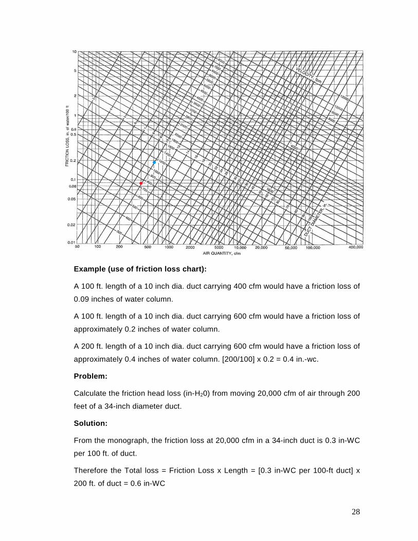
Example (use of friction loss chart):
A 100 ft. length of a 10 inch dia. duct carrying 400 cfm would have a friction loss of
0.09 inches of water column.
A 100 ft. length of a 10 inch dia. duct carrying 600 cfm would have a friction loss of
approximately 0.2 inches of water column.
A 200 ft. length of a 10 inch dia. duct carrying 600 cfm would have a friction loss of
approximately 0.4 inches of water column. [200/100] x 0.2 = 0.4 in.-wc.
Problem:
Calculate the friction head loss (in-H20) from moving 20,000 cfm of air through 200
feet of a 34-inch diameter duct.
Solution:
From the monograph, the friction loss at 20,000 cfm in a 34-inch duct is 0.3 in-WC
per 100 ft. of duct.
Therefore the Total loss = Friction Loss x Length = [0.3 in-WC per 100-ft duct] x
200 ft. of duct = 0.6 in-WC
28
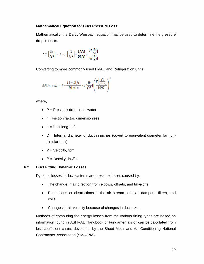
Mathematical Equation for Duct Pressure Loss
Mathematically, the Darcy Weisbach equation may be used to determine the pressure
drop in ducts.
Converting to more commonly used HVAC and Refrigeration units:
where,
• P = Pressure drop, in. of water
• f = Friction factor, dimensionless
• L = Duct length, ft
• D = Internal diameter of duct in inches (covert to equivalent diameter for non-
circular duct)
• V = Velocity, fpm
• = Density, lbm/ft3
6.2 Duct Fitting Dynamic Losses
Dynamic losses in duct systems are pressure losses caused by:
• The change in air direction from elbows, offsets, and take-offs.
• Restrictions or obstructions in the air stream such as dampers, filters, and
coils.
• Changes in air velocity because of changes in duct size.
Methods of computing the energy losses from the various fitting types are based on
information found in ASHRAE Handbook of Fundamentals or can be calculated from
loss-coefficient charts developed by the Sheet Metal and Air Conditioning National
Contractors' Association (SMACNA).
29
The total pressure loss from friction through the fittings, Ffitting, is proportional to the
velocity pressure (VP). The constant of proportionality depends on the fitting. Thus,
the total pressure loss from friction through a fitting is calculated as:
The dynamic loss coefficient (K) is measured empirically and reported by the fitting
manufacturers. Often for simplicity, an “equivalent length” method is used wherein a
type of fitting such as a T-wye or elbow is assigned a number that represents a
length of straight duct that has an equal pressure drop. For example a T-wye
might have an equivalent length of 10 feet. A ninety degree elbow might have an
equivalent length of 15 feet. A round start collar coming off of a sheet metal
supply plenum can have equivalent lengths approaching 30 feet or more. This
additional length is then added to the straight length of the duct to get the overall
effective length.
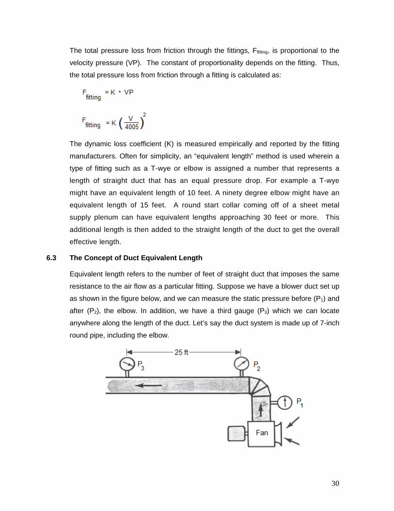
6.3 The Concept of Duct Equivalent Length
Equivalent length refers to the number of feet of straight duct that imposes the same
resistance to the air flow as a particular fitting. Suppose we have a blower duct set up
as shown in the figure below, and we can measure the static pressure before (P1) and
after (P2), the elbow. In addition, we have a third gauge (P3) which we can locate
anywhere along the length of the duct. Let’s say the duct system is made up of 7-inch
round pipe, including the elbow.
30
With 250 cfm flowing through the system, we would find that the pressure loss of the
elbow, or the difference between gauge readings P1 and P2 would be about 0.054
inches WG. Now to obtain the same pressure loss through the run of straight pipe
between gauges P2 and P3, we would find that gauge P3 must be placed 25 feet away
from gauge P2 before the losses were the same. Thus, for the condition stated, the
pressure loss of the 7-inch round elbow is equivalent to the loss of 25 ft. of 7-inch
round duct.
If we increase the air flow rate through the system we would find that to keep the
readings between gauges equal, we would have to move gauge P3 further away from
gauge P2. In other words, if we increase the flow rate to say 350 cfm, gauge P3 might
have to be placed 26 or 27 ft. away from P2 to obtain the same loss reading as
experienced by the elbow. Conversely, if we lower the flow rate, the distance between
P2 and P3 could be narrowed.
A fitting’s pressure loss thus can be conveniently expressed in terms of equivalent
length of straight duct of any size. Equivalent lengths are numbers that can be
looked up in an appendix of ACCA Manual D, ASHRAE or SMACNA guides.
Note that the equivalent length of a fitting is different from the effective length, which
is the sum of the actual measured length of a duct plus all the equivalent lengths of
the various fittings.
6.4 Pressure Loss across Components
The air handler is the single greatest pressure drop item in the ductwork. Components
in the air handling unit such as filters or coils have a definite static pressure drop
across them based on the air flow. For example, a "dry" coil may have a static
pressure drop of 0.45 inch water column at 550 fpm. A "wet" coil, which is a water coil
operating with condensate on the fins, would have a higher drop at the same velocity.
Another example of changing pressures would be a filter having a certain static
pressure drop when clean, and a higher drop when dirty. To reduce the pressure
drop, specify a low face velocity unit in the 250 to 450 fpm range. The fan power
requirement decreases approximately as the square of the velocity decrease.
7.0. FAN SIZING
In a duct system, a fan is used to supply the necessary forces to bring the fluid from
rest to the system velocity, and overcome friction forces. The force exerted by the fan
31
is the fan total pressure. The total pressure is divided into two vector components.
The first component, velocity pressure, is in the direction of the flow and whose
magnitude is positive and proportional to the velocity. The second component, static
pressure, is normal to the direction of the flow. Static pressure may be positive,
exerting outward from the frame of reference, or negative, exerting inward. Velocity
pressure is always positive, and the sum of the static and velocity pressures is the
total pressure.
7.1 Fan Selection Example
The fan must be selected to deliver a specific volumetric flow rate (cfm) and generate
static pressure (in – H2O) to overcome the pressure losses due to ducts, fitting, and the
components of an air handling unit (AHU). The total static pressure (TSP) is the sum of
the external static pressure (ESP) and internal static pressure (ISP).
TSP = ESP + ISP
where,
• ESP is the static pressure created downstream of the AHU and it includes all
the duct losses from the fan until it reaches the discharge point. This could
include a negative static pressure on the pull side of the fan and a positive
pressure on the push side, or any combination of pressures the fan must
overcome. It is estimated by the HVAC design engineer as he lays out the
ductwork, diffusers, and terminal devices.
• ISP, as it pertains to the HVAC AHU, is the static pressure loss across the filters,
coils, louvers, dampers, and twists and turns inside the AHU casing. ISP is
usually provided by the supplier, but for custom designs, the HVAC design
engineer estimates the pressure loss across the various components of the AHU.
Below is a simple model to calculate the total pressure loss (using the equal friction
method) and the selection of fan.
Example
An air conditioning layout below depicts an air handling unit (AHU) supplying cool air to
an office space. The supply air fan discharges to supply air diffusers SAD -1 & SAD - 2
through the supply duct and draws air through the return duct via the return air grille
(RAG -1). It also draws fresh air through a louver (OAL -1). Estimate the total pressure
loss for sizing the fan.
32
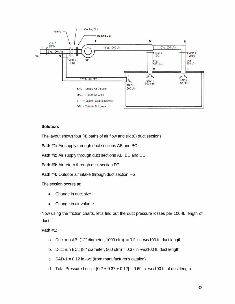
Solution:
The layout shows four (4) paths of air flow and six (6) duct sections.
Path #1: Air supply through duct sections AB and BC
Path #2: Air supply through duct sections AB, BD and DE
Path #3: Air return through duct section FG
Path #4: Outdoor air intake through duct section HG
The section occurs at:
• Change in duct size
• Change in air volume
Now using the friction charts, let’s find out the duct pressure losses per 100-ft. length of
duct.
Path #1:
a. Duct run AB; (12” diameter, 1000 cfm) = 0.2 in.- wc/100 ft. duct length
b. Duct run BC ; (8 “ diameter, 500 cfm) = 0.37 in.-wc/100 ft. duct length
c. SAD-1 = 0.12 in.-wc (from manufacturer’s catalog)
d. Total Pressure Loss = [0.2 + 0.37 + 0.12] = 0.69 in.-wc/100 ft. of duct length
33
Path #2:
a. Duct run AB; (12” diameter, 1000 cfm) = 0.2 in.-wc/100 ft. duct length
b. Duct run BD ; ( 10” diameter, 500 cfm) = 0.14 in.- wc/100 ft. duct length
c. Duct run DE; ( 8” diameter, 500 cfm) = 0.37 in.-wc/100 ft. duct length
d. SAD-2 = 0.12 in. -wc (from manufacturer’s catalog)
e. Total Pressure Loss = [0.2 + 0.14 + 0.37 + 0.12] = 0.83 in.-wc/100 ft. duct length
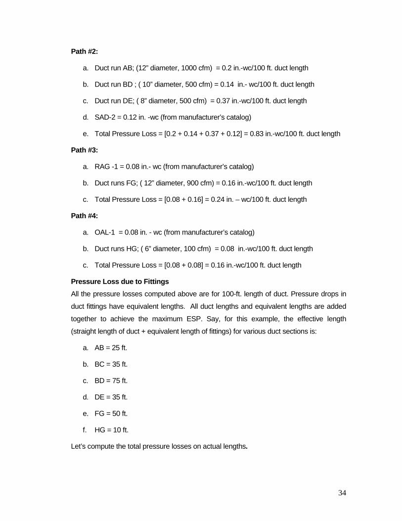
Path #3:
a. RAG -1 = 0.08 in.- wc (from manufacturer’s catalog)
b. Duct runs FG; ( 12” diameter, 900 cfm) = 0.16 in.-wc/100 ft. duct length
c. Total Pressure Loss = [0.08 + 0.16] = 0.24 in. – wc/100 ft. duct length
Path #4:
a. OAL-1 = 0.08 in. - wc (from manufacturer’s catalog)
b. Duct runs HG; ( 6” diameter, 100 cfm) = 0.08 in.-wc/100 ft. duct length
c. Total Pressure Loss = [0.08 + 0.08] = 0.16 in.-wc/100 ft. duct length
Pressure Loss due to Fittings All the pressure losses computed above are for 100-ft. length of duct. Pressure drops in
duct fittings have equivalent lengths. All duct lengths and equivalent lengths are added
together to achieve the maximum ESP. Say, for this example, the effective length
(straight length of duct + equivalent length of fittings) for various duct sections is:
a. AB = 25 ft.
b. BC = 35 ft.
c. BD = 75 ft.
d. DE = 35 ft.
e. FG = 50 ft.
f. HG = 10 ft.
Let’s compute the total pressure losses on actual lengths.
34
Path #1:
a. Duct run AB = 0.2 x 25/100 = 0.05 in. - wc
b. Duct run BC = 0.37 x 35/100 = 0.13 in.- wc
c. SAD-1 = 0.12 in.- wc
d. Total Pressure Loss = [0.05 + 0.13 + 0.12] = 0.30 in.- wc
Path #2:
a. Duct run AB= 0.2 x 25/100 = 0.05 in.- wc
b. Duct run BD = 0.14 x 75/100 = 0.10 in.- wc
c. Duct run DE = 0.37 x 35/100 = 0.13 in.- wc
d. SAD-2 = 0.12 in. - wc
e. Total Pressure Loss = [0.05 + 0.10 + 0.13 + 0.12] = 0.40 in.- wc
Path #3:
a. RAG -1 = 0.08 in.- wc
b. Duct runs FG= 0.16 x 50/100 = 0.08 in.- wc
c. Total Pressure Loss = [0.08 + 0.08] = 0.16 in. - wc
Path #4:
a. OAL-1 = 0.08 in. - wc
b. Duct runs HG = 0.08 x 10/100 = 0.008 in.- wc
c. Total Pressure Loss = [0.08 + 0.008] = 0.09 in.- wc
Maximum ESP:
Sum the pressure losses calculated for each branch from the fan to an air discharge
point. The branch with the largest pressure loss sets the system pressure drop. In our
example, Path #2 + Path #4 give the maximum pressure loss.
ESP max = 0.40 + 0.09 = 0.49 in.-wc
Equipment Loss (ISP):
a. Filters = 0.15 in.- wc (from manufacturer’s catalog)
b. Cooling Coil = 0.50 in.- wc (from manufacturer’s catalog)
35
c. Heating Coil = 0.28 in. - wc (from manufacturer’s catalog)
Maximum ISP:
Maximum ISP is the sum of component losses.
ISP max = 0.15+ 0.50 + 0.28 = 0.93 in.-wc
Fan Selection:
The fan selection shall be made based on the total pressure loss.
SP max = ESP max + ISP max
SP max = 0.49 + 0.93 = 1.42 in.-wc
Safety factor, (SF-1)
To allow for the accumulation of dirt on the filters and coils, and for possible changes in
the installation of duct work, a safety factor (10 to 15%) is usually added.
Safety factor, (SF -2)
The configuration of the fan connection to the duct at the inlet and outlet causes serious
degradation to the fan performance and is usually compensated by putting some
additional safety factor. This is called “fan system effect factor” and the value is based on
the use of charts and graphs published by the Air Movement and Control Association
(AMCA) and the Sheet Metal and Air Conditioning Contractors' National Association
(SMACNA). Alternatively, as a rule of thumb, a 10% safety factor is recommended for
system effect. Therefore, the:
Total Fan Static Requirement = SP max x SF-1x SF-2 = 1.42 x 1.15 x 1.1 = 1.8 in.-wc
Therefore, the fan must be selected to produce a pressure rise of at least 1.8 in.-wc to
overcome the ductwork system losses.
Fan Rating
Fan manufacturers usually publish characteristic curves in terms of the fan’s static
pressure rather than the fan’s total pressure. This is understandable as manufacturers
may not have control over the types of inlet and outlet duct fittings or the conditions at
the entry or exit to the inlet/outlet cones.
36

7.2 Balancing Air
An important ductwork design consideration is the pressure balance of the duct layout.
Actual air flow can exceed design flow if the fan pressure is higher than the pressure loss.
In this case, it takes partial closure of the balancing dampers, which control the air flow, to
get the air flow rate down to what the duct equipment was designed to handle.
Air balancing is an act of adjusting the volume control dampers to equalize the friction
losses. One of the major drawbacks of the equal friction duct sizing method is that there
is no equalization of pressure drops in duct branches, unless the system has a
symmetrical layout.
In the example above, because air will flow to the path of least resistance, it will be
necessary to adjust the balancing damper in line BC in order to divide the supply air
equally (i.e. 500 cfm per outlet). The ductwork has been installed so that the air path from
the fan discharge to SAD-2 has a total resistance of 0.40 in.-wc; whereas, the resistance
to air flow from the fan to SAD -1 is only 0.30 in .wc.
This means that SAD-1 will tend to get more air than is required and SAD-2 will receive
less than the design cfm. To balance the air in each duct line, damper BC will be adjusted
so that it will impose a resistance in line BC equal to 0.10 in.wc, which is the calculated
difference in pressure loss between the two duct runs (0.4 -0.3).
As with the supply runs, the return and outside duct runs have different pressure losses.
Therefore, in order to balance the return and outside duct lines, the outside air damper
HG will be adjusted so that it imposes a resistance of 0.07 in.-wc (the difference between
the return run and the outside air (0.09 -0.16).
7.3 Fan System Effect
Typically the fan performance curves are developed by laboratory measurements with
the fan installed under ideal conditions. However, when the duct system is connected
to the fan, the fan operating conditions are influenced and the fan performance will
get altered. The figure below shows the air velocity profiles in a duct at various
distances from the outlet of a housed centrifugal fan. The air in the fan is pushed
against the outside of the housing by the movement of the fan wheel. Therefore, at
the fan outlet, there is a high velocity at the top of the fan outlet. However, at the
bottom of the fan outlet there is a negative velocity, because the air is swirling
back to the fan at the cut-off plate, attempting to re-enter the fan.
37

At point A in the figure, the velocity pressure is high and the available static
pressure is low. As the air moves down the duct, the velocity of the air becomes
more uniform across the duct, and the static pressure increases as the velocity
pressure decreases. At point B in the figure, the air velocity is uniform across the
duct, and low compared to the outlet velocity (point A).
Fan outlet velocity profile
Remember that total pressure is the sum of the velocity pressure and the static
pressure. The total pressure in the duct at point B is about the same as it was at
point A; therefore, as the velocity pressure has decreased, the static pressure has
increased. In other words, the system has gained static pressure. This is static
regain. The system now has more potential to overcome the resistance in the
system and, thus, the system can deliver more air. At point B, the air velocity is
uniform across the duct area and has slowed. This is the point of highest static
regain. Duct takeoffs and turns or elbows should be avoided prior to point B
because air flow in ducts attached prior to point B will have significant system
effect losses that must be accounted for in the sizing of the duct and fan. The
distance from A to B is called the 100% effective duct length. The housed fan
outlet should be designed with straight duct for the 100% effective duct length,
and fittings should not be put near the fan outlet, in order to eliminate system
effect at the outlet.
To achieve 100% effective duct length, a straight run from the blower, has to be long
enough to achieve a uniform Velocity across the cross-section of the duct.
Calculating the 100% effective duct length depends upon the air velocity at the fan
outlet:
38
a. If the outlet velocity is less than 2,500 fpm:
100% effective duct length = 2.5 x duct diameter
b. If the outlet velocity is more than 2,500 fpm:
100% effective duct length = fpm/1000 x duct diameter
c. To calculate the duct diameter:
D = 2wh / (w +h), where h and w are duct height and width, respectively.
Causes of System Effect
The four most common causes of system effect on the fan are:
1. Uneven air flow into the fan inlet
2. Spinning air at the fan inlet
3. Obstructions at the fan inlet or outlet
4. Improper duct connections at the fan outlet or inlet
Fan System Effect Corrections at Design
1. Use of the “six-and-three rule” minimizes system loss. Provide six diameters
of straight duct at the fan suction and three diameters of straight duct at the
fan discharge.
2. Use as long a straight duct as possible for the job conditions. The first elbow in
the ducting leaving the unit should be no closer than 2 feet from the unit to
minimize resistance and noise.
3. AMCA Standard 210 specifies an outlet duct that is not greater than 107.5
percent or less than 87.5 percent of the fan outlet area.
4. If a duct transition must be used, slant the sides as gradually as possible.
AMCA Standard 210 requires that the slope of the transition should not be
greater than 15 percent for converging transitions, or greater than 7 percent
for diverging transitions.
5. For maximum performance, the air should enter straight into the fan inlet, with
a uniform velocity across the area of the inlet. The ideal inlet connection is a
long, straight duct with a length four times the diameter of the inlet. If an elbow
39
is required, there should be a length of straight duct between the fan inlet and
the elbow at least two times the diameter of the fan inlet.
6. If a free inlet is required, the inlet duct can be replaced with an inlet bell
which provides a smooth transition to the fan velocity with no loss in total
pressure.
7. A straight duct for a distance of three to six duct diameters from the fan
discharge should be used in order to develop a full dynamic head.
Branching and turning sooner causes system effect losses.
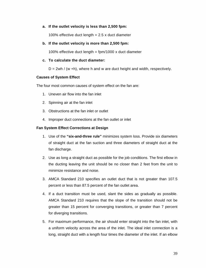
8.0. THE SUPPLY DUCT SYSTEM
The two most common supply duct systems are the ‘extended plenum’ system and
the ‘radial’ system. The other options are spider and perimeter loop systems.
8.1 Extended Plenum Systems
In the extended plenum systems, a large main supply trunk of equal size is
connected directly to the air handler. Smaller branch ducts and run-outs are
connected to the trunk. The arrangement provides air flows that are easily
balanced and can be easily designed to be located inside the conditioned space of
the building.
The principal design limitation of the extended plenum is the maximum length of the
main supply trunk (of single size), which is usually limited to about 24 feet. When this
length is exceeded, pressure tends to build up toward the end of the duct, resulting in
too much air flow near the ends and insufficient air flow in branches closer to the air
handler.
40
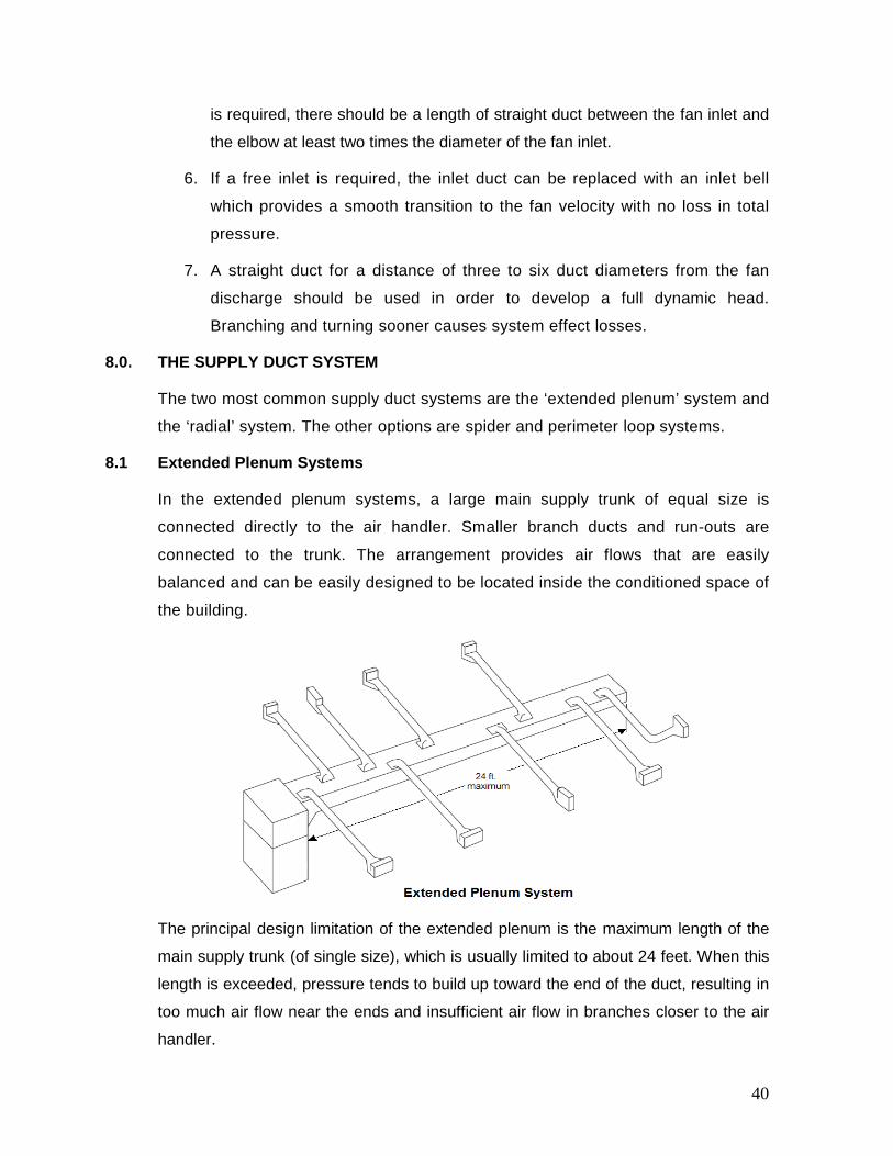
However, the extended plenum system can be modified to provide a double span, up
to 48 feet long, when the equipment is centrally located. See the figure below.
General rules:
The following general rules apply for the extended plenum system:
• Single plenums should not exceed 24 ft. in length.
• Double plenums should not exceed 48 ft. in total length.
• Keep branch run starting collars 24 in. from the end caps.
• Never locate a takeoff in the end cap.
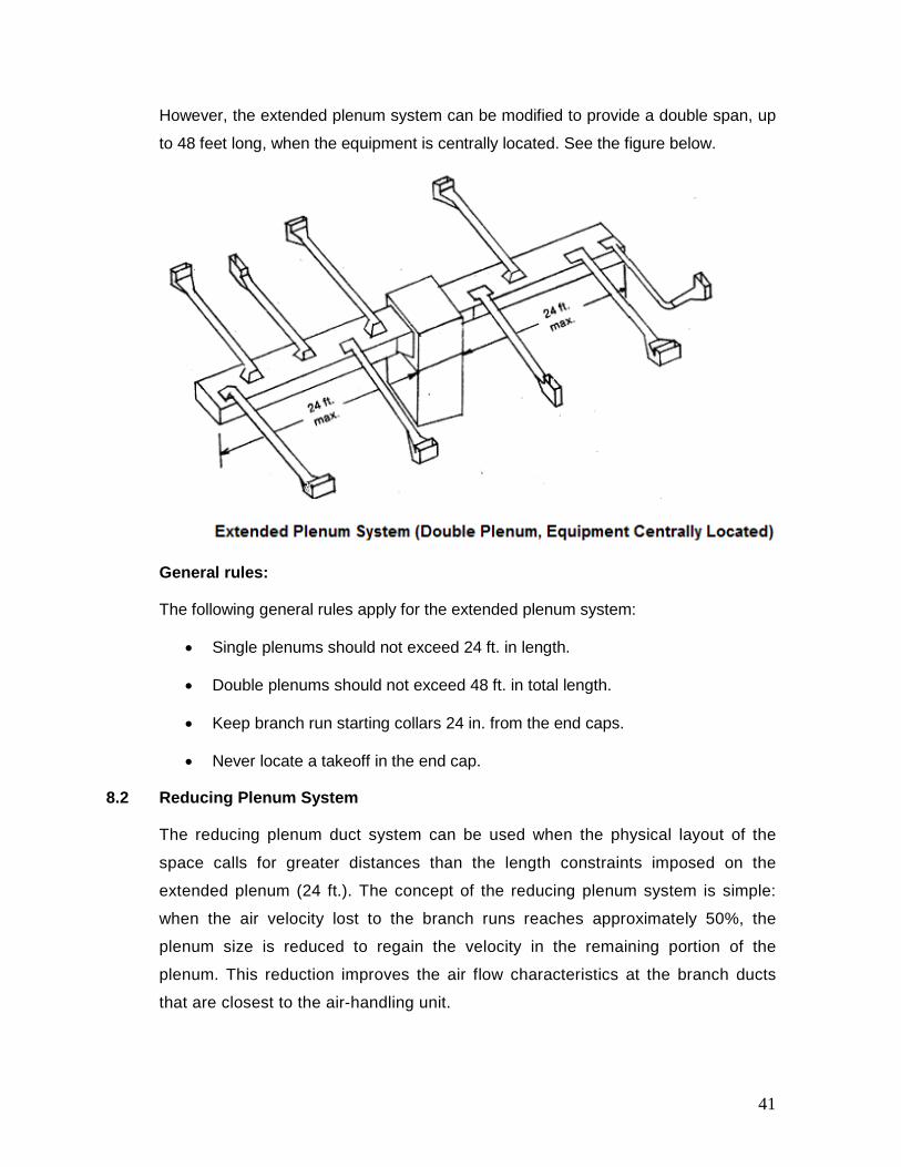
8.2 Reducing Plenum System
The reducing plenum duct system can be used when the physical layout of the
space calls for greater distances than the length constraints imposed on the
extended plenum (24 ft.). The concept of the reducing plenum system is simple:
when the air velocity lost to the branch runs reaches approximately 50%, the
plenum size is reduced to regain the velocity in the remaining portion of the
plenum. This reduction improves the air flow characteristics at the branch ducts
that are closest to the air-handling unit.
41
Another variation of this system is the reduced trunk system described below.
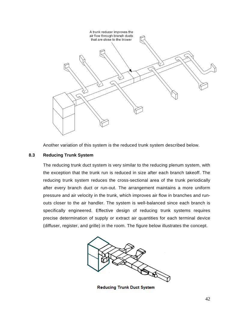
8.3 Reducing Trunk System
The reducing trunk duct system is very similar to the reducing plenum system, with
the exception that the trunk run is reduced in size after each branch takeoff. The
reducing trunk system reduces the cross-sectional area of the trunk periodically
after every branch duct or run-out. The arrangement maintains a more uniform
pressure and air velocity in the trunk, which improves air flow in branches and run-
outs closer to the air handler. The system is well-balanced since each branch is
specifically engineered. Effective design of reducing trunk systems requires
precise determination of supply or extract air quantities for each terminal device
(diffuser, register, and grille) in the room. The figure below illustrates the concept.
42
Obviously, this type of system generally takes more sheet metal to build and
requires more labor to fabricate and install.
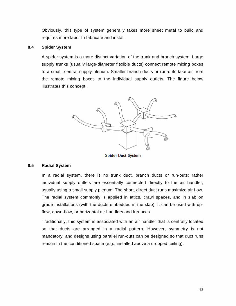
8.4 Spider System
A spider system is a more distinct variation of the trunk and branch system. Large
supply trunks (usually large-diameter flexible ducts) connect remote mixing boxes
to a small, central supply plenum. Smaller branch ducts or run-outs take air from
the remote mixing boxes to the individual supply outlets. The figure below
illustrates this concept.
8.5 Radial System
In a radial system, there is no trunk duct, branch ducts or run-outs; rather
individual supply outlets are essentially connected directly to the air handler,
usually using a small supply plenum. The short, direct duct runs maximize air flow.
The radial system commonly is applied in attics, crawl spaces, and in slab on
grade installations (with the ducts embedded in the slab). It can be used with up-
flow, down-flow, or horizontal air handlers and furnaces.
Traditionally, this system is associated with an air handler that is centrally located
so that ducts are arranged in a radial pattern. However, symmetry is not
mandatory, and designs using parallel run-outs can be designed so that duct runs
remain in the conditioned space (e.g., installed above a dropped ceiling).
43
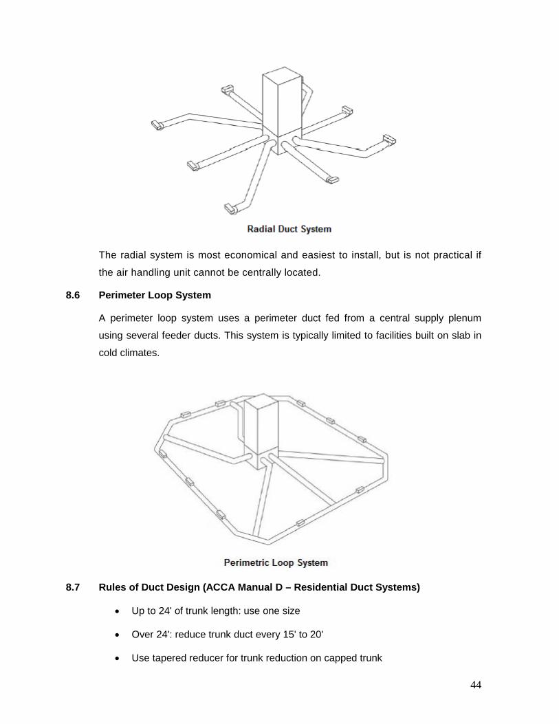
The radial system is most economical and easiest to install, but is not practical if
the air handling unit cannot be centrally located.
8.6 Perimeter Loop System
A perimeter loop system uses a perimeter duct fed from a central supply plenum
using several feeder ducts. This system is typically limited to facilities built on slab in
cold climates.
8.7 Rules of Duct Design (ACCA Manual D – Residential Duct Systems)
• Up to 24' of trunk length: use one size
• Over 24': reduce trunk duct every 15' to 20'
• Use tapered reducer for trunk reduction on capped trunk
44
• Standard trunk is 8" high
• Trunk width not to exceed trunk height by more than 4 times
• Use offset take-offs rather than straight take-offs
• Stagger the branch take-offs
• Damper each run as close to the trunk as possible
• Neither branch off any closer than 12" to the end nor off the end of a trunk
• No take-off 4' after a reduction or 1.5 times the greater dimension of the duct
• Never take-off a reduction or increase the mains any closer than the diameter
of the branch duct
• On supply and return, when the trunk is wider than the plenum, a transition
fitting must be used
9.0. RETURN DUCT SYSTEMS
Air conditioning systems not only supply air flow to rooms, but they pull air out of
the rooms, also. If the return flow is not free to exit the space, the pressure will
build up in the room and the lost air must be replaced. This causes increased
quantities of outside air, which can bring additional heat, humidity and other
undesirable elements with it. The supply air must therefore be balanced to
maintain neutral air pressure within the space. This is done by designing ductwork
with an adequate number of return ducts (or grilles). Return duct systems are
generally classified as either central or distributed return.
9.1 Distributed Return
In a distributed return, each room has a return duct that provides a pathway for air to
flow back to the air handler. The scheme ensures that the air flow is returned from all
rooms, avoids too much positive pressurization, minimizes pressure imbalances,
improves privacy, and is quiet. However, design and installation costs are generally
higher than for a central return system, and higher friction losses can increase blower
requirements.
9.2 Central Return
In a central return duct system, return grilles are located in central locations on the
common plenum, usually close to the air handler. To ensure proper air flow from all
45
rooms, especially when doors are closed, transfer grilles or jumper ducts must be
installed in each room.
Central return ducts should have at least one 90 degree bend between the air handler
unit and the central return grille, and the air speed at the face of the return grille
should be designed at 350 fpm. This keeps noise in check while allowing enough
negative pressure in the return box to draw in outside air with the central-fan-
integrated supply ventilation system. To size the return grille, use the equation below
and divide the result by 0.65 to account for about 65% free area, which is normal for
stamped return grilles.
A = q / v
where,
• A = area in square feet
• v = air speed (ft/min)
• q = volumetric air flow rate (cfm)
Central return duct systems offer the following advantages:
• They require less ductwork than a distributed system.
• They lower energy loss, since larger plenum space provides a more direct
path for air flow.
• They reduce installation time and cost of materials.
9.3 Pressure Balancing
The return openings will need to be 2 to 3 times the size of the supply duct depending
on system design velocities. This can take the form of transfer grille and jump ducts.
1. Transfer Grilles: They allow air to move from one space to another to
alleviate pressure differences. For example, a transfer grille installed above a
bedroom door enables air to move between the bedroom and the hallway,
regardless of whether the door is open or closed. Door undercutting can help
as well (for example ¾ inch undercut of a 32” door will create 24 sq. in. open
area) but isn't normally sufficient on its own. A transfer grille and/or jump ducts
are often required to equalize pressure and prevent over pressurization of
46
spaces. A “Rule of Thumb” considers 1 square inch of wall opening per cfm
delivered to the room.
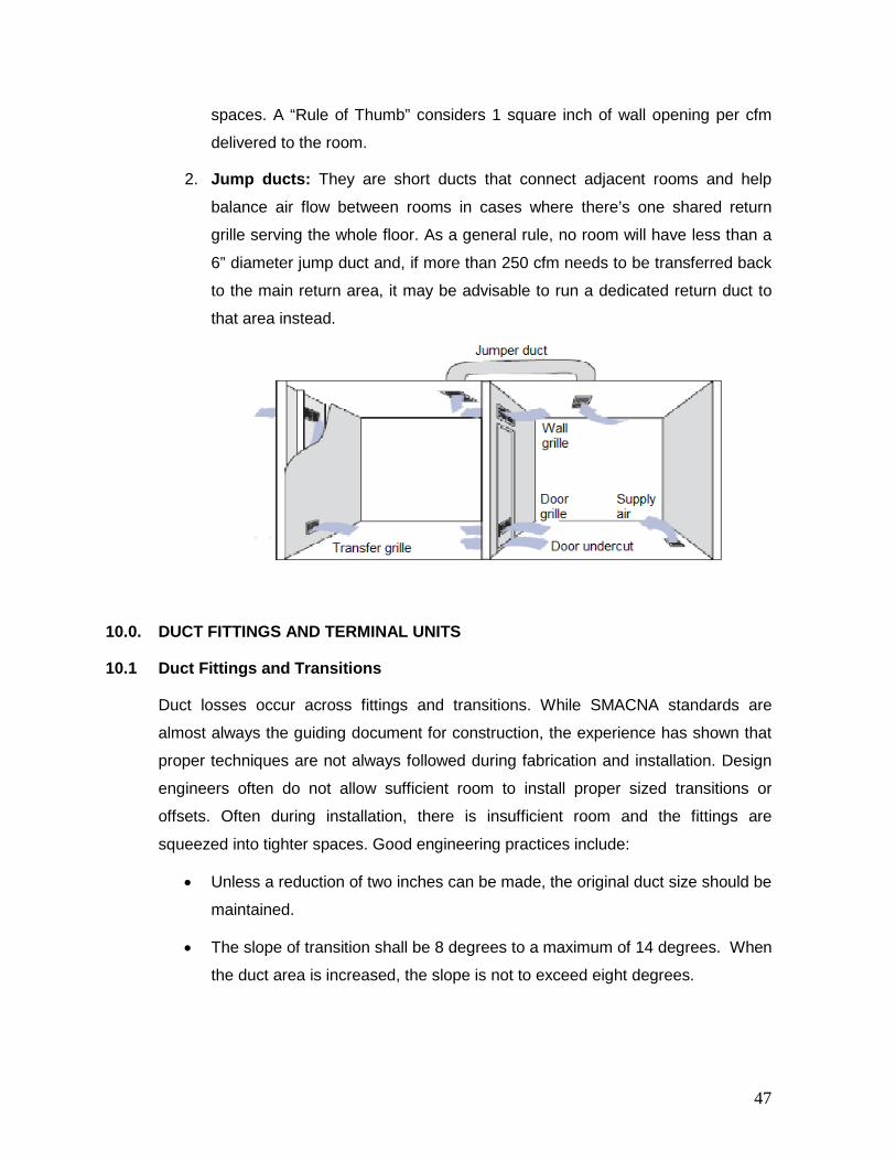
2. Jump ducts: They are short ducts that connect adjacent rooms and help
balance air flow between rooms in cases where there’s one shared return
grille serving the whole floor. As a general rule, no room will have less than a
6” diameter jump duct and, if more than 250 cfm needs to be transferred back
to the main return area, it may be advisable to run a dedicated return duct to
that area instead.
10.0. DUCT FITTINGS AND TERMINAL UNITS
10.1 Duct Fittings and Transitions
Duct losses occur across fittings and transitions. While SMACNA standards are
almost always the guiding document for construction, the experience has shown that
proper techniques are not always followed during fabrication and installation. Design
engineers often do not allow sufficient room to install proper sized transitions or
offsets. Often during installation, there is insufficient room and the fittings are
squeezed into tighter spaces. Good engineering practices include:
• Unless a reduction of two inches can be made, the original duct size should be
maintained.
• The slope of transition shall be 8 degrees to a maximum of 14 degrees. When
the duct area is increased, the slope is not to exceed eight degrees.
47
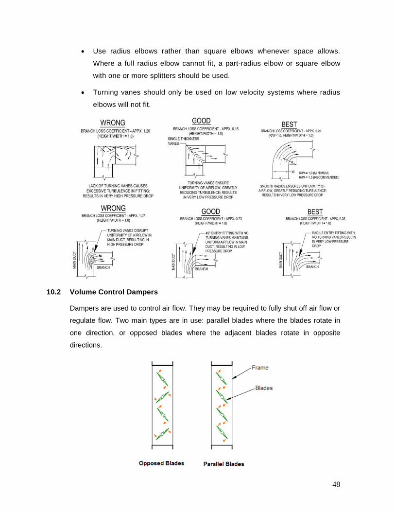
• Use radius elbows rather than square elbows whenever space allows.
Where a full radius elbow cannot fit, a part-radius elbow or square elbow
with one or more splitters should be used.
• Turning vanes should only be used on low velocity systems where radius
elbows will not fit.
10.2 Volume Control Dampers
Dampers are used to control air flow. They may be required to fully shut off air flow or
regulate flow. Two main types are in use: parallel blades where the blades rotate in
one direction, or opposed blades where the adjacent blades rotate in opposite
directions.
48

Pressure loss across the damper and leakage through a closed damper are two
performance criteria affecting the selection of dampers. Parallel blade dampers are
best suited for full-open or closed requirements or for fine control between 80% to
100% full flow. Opposed blade dampers are best for systems where air volume is
changed over a wide range. AMCA recommends using an opposed-blade damper
when volume control is needed. Balancing/volume adjusting dampers should be installed close to the main supply, as
far away as possible from the outlets. Terminal dampers such as those used in
registers and diffusers should not be considered in branch balancing as they are
meant to be used for fine adjustment only and would normally be in an almost fully
open position to prevent unnecessary noise.
10.3 Fire and Smoke Dampers
A fire damper is a device installed in ducts and air transfer openings to interrupt the
passage of flame and maintain the integrity of the fire rated separation. Fire dampers
are equipped with a fusible link (rated for 165°F up to 286°F) that holds the blades
open until it the link melts. Upon reaching the melting point, the blades then close and
stop the flame from moving into an adjoining compartment.
Location: Fire dampers shall be installed in or near the wall or floor, at the point of
duct penetration, to retain the integrity and fire rating of a wall or floor whether it is a
ducted or open-plenum return application. Should the ductwork fall away, the damper
needs to stay in the wall or floor to maintain the integrity of the wall or floor. One
should actually think of the fire damper as part of the wall system itself.
Smoke dampers are defined as a device designed to resist the passage of smoke
through the HVAC system, or from one side of a fire-rated separation to the other.
Location: They must be installed no more than 24 inches from the smoke barrier. Of
course, smoke dampers that are used to isolate air handlers are not limited to this
distance requirement. NFPA 90A states that smoke dampers are to be used to isolate
air handling units over 15,000 cfm.
10.4 Diffusers, Grilles & Registers
Diffusers are the terminal devices that supply air in various directions through the use
of their deflecting vanes. These are designed to promote the mixing of conditioned air
with the air already in the space.
49

Grilles are defined as air devices that are typically used to return air back to the fan or
to exhaust air from a space. Grilles are generally not used in supply distribution due to
their inability to control the air.
Registers look like grilles but are comprised of one-way or two-way adjustable air
stream deflectors and dampers to restrict the amount of air flow required to be
returned, supplied or exhausted.
Steps for Selecting Air Terminals:
a. Determine the air flow requirement and room size.
b. Select the appropriate diffuser.
c. Determine the velocity, throw, noise and pressure drop across the diffuser.
Let’s check the characteristics of diffuser (item c) with a help of an example. Table
below provides performance conditions of typical diffusers:
Air flow (cfm) 50 60 70 85 95 110 120
Velocity (fpm) 400 500 600 700 800 900 1000
Pressure drop
(in.-wc)
0.056 0.090 0.131 0.175 0.225 0.290 0.355
Noise (NC) 14 20 24 28 32 35 38
Throw (ft) 5-8-13 7-9-12 8-12-19 9-13-18 10-15-21 12-17-24 13-19-31
Air velocity: It is the normal air velocity used for comfortable air distribution is 50 fpm
while the acceptable range is from 25 to 75 fpm.
Pressure drop: It is the pressure drop across the diffuser increases at higher
velocities.
Noise Criteria (NC): NC increases at higher velocities. If a typical space requires a
NC rating of 28-32, the corresponding maximum air flow is somewhere between 85
and 95 cfm.
Throw: Throw is defined as the horizontal distance from a diffuser at a specified
velocity. For example, T50 = 15’, indicates that at a distance of 15’ from the diffuser,
the velocity of the air will be 50 feet per minute. T100 = 10’, indicates the distance at
50
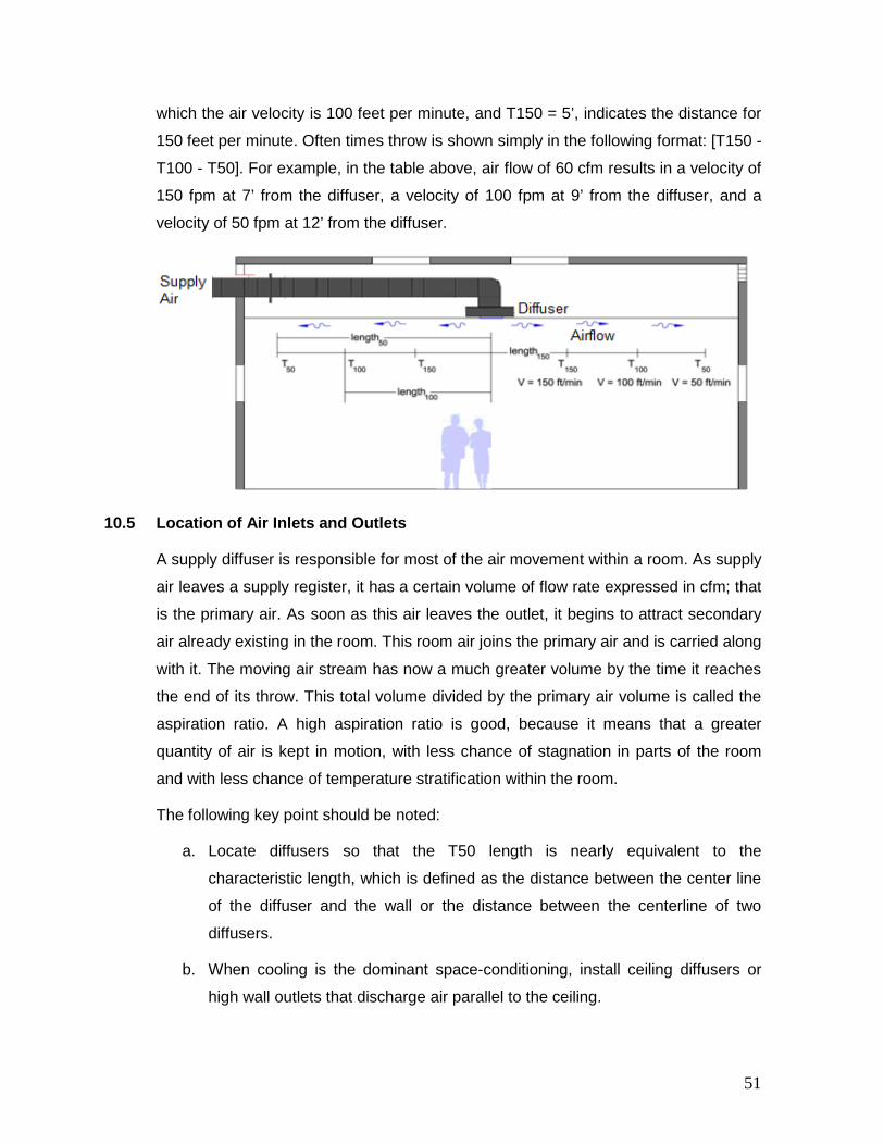
which the air velocity is 100 feet per minute, and T150 = 5’, indicates the distance for
150 feet per minute. Often times throw is shown simply in the following format: [T150 -
T100 - T50]. For example, in the table above, air flow of 60 cfm results in a velocity of
150 fpm at 7’ from the diffuser, a velocity of 100 fpm at 9’ from the diffuser, and a
velocity of 50 fpm at 12’ from the diffuser.
10.5 Location of Air Inlets and Outlets
A supply diffuser is responsible for most of the air movement within a room. As supply
air leaves a supply register, it has a certain volume of flow rate expressed in cfm; that
is the primary air. As soon as this air leaves the outlet, it begins to attract secondary
air already existing in the room. This room air joins the primary air and is carried along
with it. The moving air stream has now a much greater volume by the time it reaches
the end of its throw. This total volume divided by the primary air volume is called the
aspiration ratio. A high aspiration ratio is good, because it means that a greater
quantity of air is kept in motion, with less chance of stagnation in parts of the room
and with less chance of temperature stratification within the room.
The following key point should be noted:
a. Locate diffusers so that the T50 length is nearly equivalent to the
characteristic length, which is defined as the distance between the center line
of the diffuser and the wall or the distance between the centerline of two
diffusers.
b. When cooling is the dominant space-conditioning, install ceiling diffusers or
high wall outlets that discharge air parallel to the ceiling.
51
c. A return air inlet that is located directly in the primary air stream of the supply
outlet will short circuit the supply air back into the return without mixing with
room air. Place the returns high when cooling is the dominant factor, and low
when heating is the dominant factor.
d. Special situations that require careful attention by the designer are the location
of return and exhaust inlets in bars, kitchens, lavatories, dining rooms, club
rooms, etc. These normally should be located near or at the ceiling level to
collect the warm air "build-up," odors, smoke, and fumes.
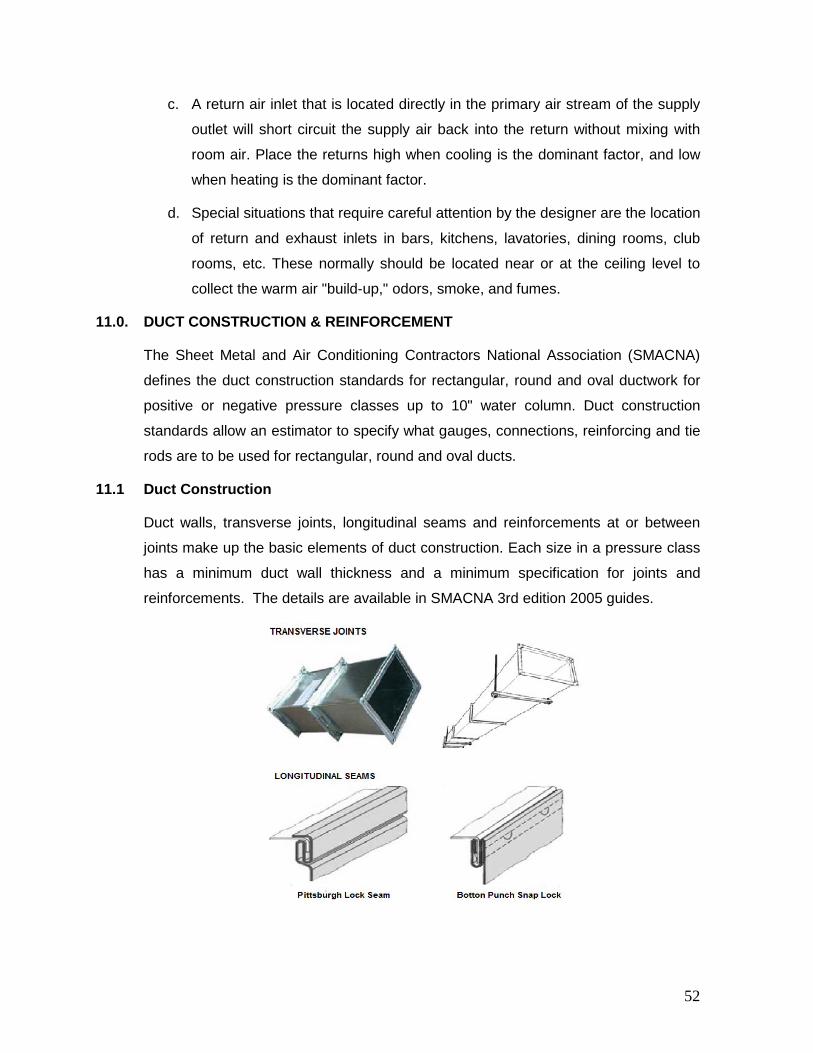
11.0. DUCT CONSTRUCTION & REINFORCEMENT
The Sheet Metal and Air Conditioning Contractors National Association (SMACNA)
defines the duct construction standards for rectangular, round and oval ductwork for
positive or negative pressure classes up to 10" water column. Duct construction
standards allow an estimator to specify what gauges, connections, reinforcing and tie
rods are to be used for rectangular, round and oval ducts.
11.1 Duct Construction
Duct walls, transverse joints, longitudinal seams and reinforcements at or between
joints make up the basic elements of duct construction. Each size in a pressure class
has a minimum duct wall thickness and a minimum specification for joints and
reinforcements. The details are available in SMACNA 3rd edition 2005 guides.
52
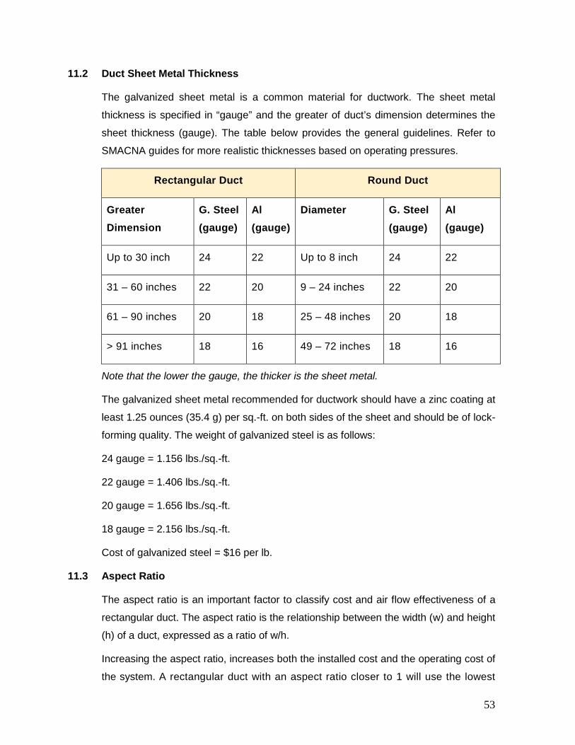
11.2 Duct Sheet Metal Thickness
The galvanized sheet metal is a common material for ductwork. The sheet metal
thickness is specified in “gauge” and the greater of duct’s dimension determines the
sheet thickness (gauge). The table below provides the general guidelines. Refer to
SMACNA guides for more realistic thicknesses based on operating pressures.
Rectangular Duct Round Duct
Greater Dimension
G. Steel (gauge)
Al (gauge)
Diameter G. Steel (gauge)
Al (gauge)
Up to 30 inch 24 22 Up to 8 inch 24 22
31 – 60 inches 22 20 9 – 24 inches 22 20
61 – 90 inches 20 18 25 – 48 inches 20 18
> 91 inches 18 16 49 – 72 inches 18 16
Note that the lower the gauge, the thicker is the sheet metal.
The galvanized sheet metal recommended for ductwork should have a zinc coating at
least 1.25 ounces (35.4 g) per sq.-ft. on both sides of the sheet and should be of lock-
forming quality. The weight of galvanized steel is as follows:
24 gauge = 1.156 lbs./sq.-ft.
22 gauge = 1.406 lbs./sq.-ft.
20 gauge = 1.656 lbs./sq.-ft.
18 gauge = 2.156 lbs./sq.-ft.
Cost of galvanized steel = $16 per lb.
11.3 Aspect Ratio
The aspect ratio is an important factor to classify cost and air flow effectiveness of a
rectangular duct. The aspect ratio is the relationship between the width (w) and height
(h) of a duct, expressed as a ratio of w/h.
Increasing the aspect ratio, increases both the installed cost and the operating cost of
the system. A rectangular duct with an aspect ratio closer to 1 will use the lowest
53
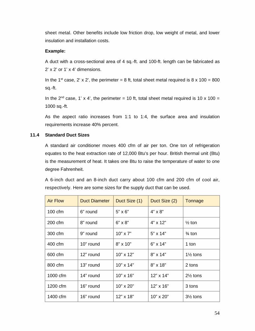
sheet metal. Other benefits include low friction drop, low weight of metal, and lower
insulation and installation costs.
Example:
A duct with a cross-sectional area of 4 sq.-ft. and 100-ft. length can be fabricated as
2’ x 2’ or 1’ x 4’ dimensions.
In the 1st case, 2‘ x 2’, the perimeter = 8 ft, total sheet metal required is 8 x 100 = 800
sq.-ft.
In the 2nd case, 1’ x 4’, the perimeter = 10 ft, total sheet metal required is 10 x 100 =
1000 sq.-ft.
As the aspect ratio increases from 1:1 to 1:4, the surface area and insulation
requirements increase 40% percent.
11.4 Standard Duct Sizes
A standard air conditioner moves 400 cfm of air per ton. One ton of refrigeration
equates to the heat extraction rate of 12,000 Btu’s per hour. British thermal unit (Btu)
is the measurement of heat. It takes one Btu to raise the temperature of water to one
degree Fahrenheit.
A 6-inch duct and an 8-inch duct carry about 100 cfm and 200 cfm of cool air,
respectively. Here are some sizes for the supply duct that can be used.
Air Flow Duct Diameter Duct Size (1) Duct Size (2) Tonnage
100 cfm 6” round 5” x 6” 4” x 8”
200 cfm 8” round 6” x 8” 4” x 12” ½ ton
300 cfm 9” round 10” x 7” 5” x 14” ¾ ton
400 cfm 10” round 8” x 10” 6” x 14” 1 ton
600 cfm 12” round 10” x 12” 8” x 14” 1½ tons
800 cfm 13” round 10” x 14” 8” x 18” 2 tons
1000 cfm 14” round 10” x 16” 12” x 14” 2½ tons
1200 cfm 16” round 10” x 20” 12” x 16” 3 tons
1400 cfm 16” round 12” x 18” 10” x 20” 3½ tons
54
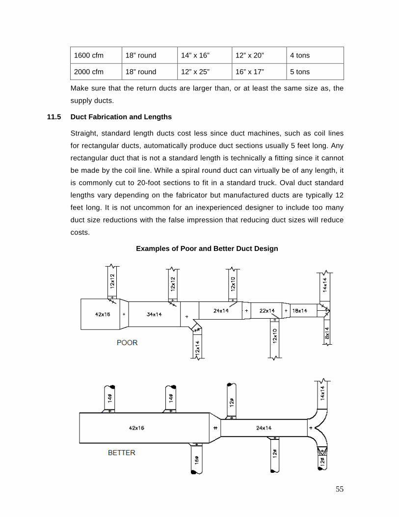
1600 cfm 18” round 14” x 16” 12” x 20” 4 tons
2000 cfm 18” round 12” x 25” 16” x 17” 5 tons
Make sure that the return ducts are larger than, or at least the same size as, the
supply ducts.
11.5 Duct Fabrication and Lengths
Straight, standard length ducts cost less since duct machines, such as coil lines
for rectangular ducts, automatically produce duct sections usually 5 feet long. Any
rectangular duct that is not a standard length is technically a fitting since it cannot
be made by the coil line. While a spiral round duct can virtually be of any length, it
is commonly cut to 20-foot sections to fit in a standard truck. Oval duct standard
lengths vary depending on the fabricator but manufactured ducts are typically 12
feet long. It is not uncommon for an inexperienced designer to include too many
duct size reductions with the false impression that reducing duct sizes will reduce
costs.
Examples of Poor and Better Duct Design
55
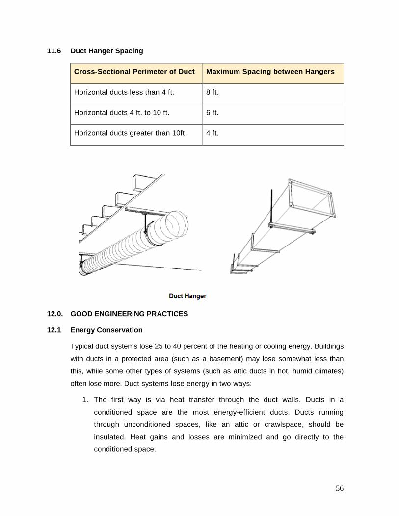
11.6 Duct Hanger Spacing
Cross-Sectional Perimeter of Duct Maximum Spacing between Hangers
Horizontal ducts less than 4 ft. 8 ft.
Horizontal ducts 4 ft. to 10 ft. 6 ft.
Horizontal ducts greater than 10ft. 4 ft.
12.0. GOOD ENGINEERING PRACTICES
12.1 Energy Conservation
Typical duct systems lose 25 to 40 percent of the heating or cooling energy. Buildings
with ducts in a protected area (such as a basement) may lose somewhat less than
this, while some other types of systems (such as attic ducts in hot, humid climates)
often lose more. Duct systems lose energy in two ways:
1. The first way is via heat transfer through the duct walls. Ducts in a
conditioned space are the most energy-efficient ducts. Ducts running
through unconditioned spaces, like an attic or crawlspace, should be
insulated. Heat gains and losses are minimized and go directly to the
conditioned space.
56

2. The second is via air leakages through accidental holes or through open
spaces between poorly connected sections of ductwork. Leaky supply
ducts cause depressurization of the structure, and outside air is forced in
through cracks in the envelope. Leaky return ducts cause pressurization,
which forces conditioned inside air out of the structure. Sealing both supply
and return ducts minimizes energy loss by infiltration.
12.2 Good Engineering Practices for Designing Ductwork
Air distribution within the space is critical to maintaining space conditions and
minimizing noise concerns. Here are some key guidelines for designing ductwork
that should be followed to get the most out of your system:
1. Configuration: Ducts should be designed so that the length of each run
(each section of ductwork) is short enough to provide proper control of air
flow and stability of construction. Radial or trunk-&-branch configurations
have shorter runs and generally work best. Wherever possible, ducts
should be located within the conditioned space. Long meandering sections
of ductwork can lead to trouble, such as ducts collapsing over time or
becoming twisted and blocked.
2. Go straight: this is the most important rule of all. From an energy
perspective, air wants to go straight and will lose energy if you make it
bend. From a cost perspective, straight duct costs less than fittings. Fittings
are expensive because they must be hand assembled even if the pieces
are automatically cut by plasma cutters. So, when laying out a system, try
to reduce the number of bends and turns to an absolute minimum.
3. Make sure ducts are the correct size: Ductwork that’s too small won’t be
able to carry enough air to heat or cool your building. Ducts that are too
large can lose both air and energy, cutting system efficiency, and wasting
money. Use trusted industry standards and procedures, such as those
published by ASHRAE, to size your ducts.
4. Make sure there are enough return ducts: Supply ducts carry
conditioned air to your building, but the system also requires enough return
ducts to bring expended air back to the HVAC unit to be conditioned again.
Each room that receives heating or cooling should have at least one return
duct. As a rule of thumb, use 2 cfm for each sq.-inch of return air opening;
57
for example, 20” x 20” grille equals 400 sq.-in. gross area of grille, which
means 800 cfm of recommended air flow.
5. Be careful where you install ducts: Ducts placed in conditioned spaces
are more efficient than those placed in unconditioned spaces. If located
within conditioned space, conductive and radiative losses, leakage losses,
and equipment cabinet losses are reduced or regained into the building
space. If it is not feasible to locate ductwork within conditioned spaces, the
ducts should be properly sealed and insulated. The trunk ducts are usually
located above corridors in the cavity above the ceiling to minimize noise
transmission to the conditioned zones and allow easy access without
disturbing the building occupants.
6. Thermal Zoning: Zoning is a practice of dividing a building into distinct
thermal zones, which have similar heating and cooling requirements. In
practice the corner rooms and the perimetric spaces of the building have
variations in load as compared to the interior core areas. The buildings are
usually divided into two major zones.
• Exterior Zone: This is the area inward from the outside wall (usually
12 to 18 feet, if rooms do not line the outside wall). The exterior zone is
directly affected by outdoor conditions during summer and winter and
has variable thermal loads.
• Interior Zone: This is the area contained by the external zone. The
interior zone is only slightly affected by outdoor conditions and usually
has a uniform and steady cooling load throughout.
Few areas, for example, conference and meeting rooms are influenced by
variable occupancy loads. The concept of thermal zone is important to size
HVAC equipment and plan the way ducting is routed. If zones have special
temperature and/or humidity requirements, they should be served by
independent air distribution systems separate from variable zones. The
idea is to permit independent control of temperature and humidity in similar
zones. Where it is not possible, consider use of VAV systems and/or
supplementary controls.
58
7. Seal and insulate: Make sure all ductwork sections fit together tightly.
Connections can be mechanically sealed with sheet metal screws or other
fasteners to improve connection strength. Seal connections with mastic or
metal tape. Cover the ductwork with insulation, such as rigid fiber board or
standard blanket-type insulation.
8. Rules of Thumb:
• 10% Rule: For supply ducts longer than 10 feet, the air is reduced
in that run by 10% for every 5 feet over 10 feet. For example, a 30
foot run yields a reduction of 40% (30-10=20, 20÷5=4, 4×10=40%).
Minimize length and restrictions. Keep the supply duct length as
close to 10 feet as possible but never less than 6 feet. Use the
fewest number of bends as possible.
• 24-inch Rule: Use at least 24 inches of straight plenum before any
fitting, such as an elbow, tee, or takeoff. Electric duct heaters
require 48 inches. Avoid elbows directly off units. The maximum
total plenum length should be restricted to 150 ft. For the plenum,
maximize length and minimize restrictions.
• 60/40 Rule: When using a tee, split the flow as close to 50/50 as
possible, no more than 60/40. Always use a turning vane.
• 70/30 Rule: Turn the tee 90° to make a side branch with no more
than 30 percent of the air. Do not use a turning vane.
• Takeoffs: Maintain distance between takeoffs as evenly as
possible. Space the takeoffs at least 6 inches apart and 12 inches
from the end cap.
• Fittings: Use long and radiused duct fittings instead of short or
mitered fittings wherever possible.
13.0. DUCTWORK INSULATION AND SEALING
13.1 Ductwork Insulation
Insulation is applied to ductwork to minimize the rate of thermal loss through the
skinny sheet metal. Ducts may also sweat when their surface temperature is below
59

the dew point of the surrounding air. This can lead to water damage and microbial
growth within the building.
A 15°F temperature difference from the inside of the duct to the outside of the duct
is considered the maximum difference allowed before insulation is necessary. One-inch-thick fiberglass blanket (R value of 16) is almost always sufficient for
thermal protection. Return air ducts only need to be insulated if they pass through
environments that adversely affect the return air temperature.
The insulation is joined by lapping it, stapling it, and taping it. A protective cover with a
vapor barrier such as an aluminum foil should be included in the insulation
specifications.
13.2 Ductwork Air Leakage
Duct leakage refers to the leakage of air from the air distribution system ductwork.
The leakage can occur at joints, seams and penetrations. This leakage causes two
problems: 1) some areas at the end of the run may be short of air flow, and 2) the
fan energy increases as the cube of the air leakage increases. For example, if a
system has 10% leakage and the fan design was originally 20 Horsepower (HP),
the new motor required to overcome the 10% loss will be 20 HP x (1.1)3 = 26.6
HP. In this case, the owner pays the equivalent of 6.6 HP in additional fan energy
for the life of the building.
The air duct leakage can be represented as a function of the duct surface area,
leakage class, and static pressure. Leakage class is determined by the
construction methods employed in duct fabrication in accordance with the ANSI/
SMACNA HVAC duct construction standards.
13.3 Duct Leakage Tests
Ductwork that is designed to operate at static pressures in excess of 3 inches
Water Column and is located outdoors shall be leak-tested according to the
SMACNA HVAC Air Duct Leakage Test Manual. Positive pressure leakage testing
is acceptable for negative pressure ductwork. The maximum permitted duct
leakage shall be:
Lmax = (CL) * (P) 0.65
where,
60
• Lmax = maximum permitted leakage in cfm/100 square feet of duct surface
area;
• CL = duct leakage class, cfm/100 square feet of duct surface area at 1 inch
Water Column. SMACNA has defined duct leakage rates as Leakage Class
24, 12 or 6. These numbers simply mean that at 1 inch of test pressure,
ducts can be expected to leak 24, 12 or 6 cfm per a square foot of duct
surface.
• P = test pressure, which is equal to the design duct pressure class rating,
in inch Water Column, based on ASHRAE 90.1:6.4.4.2.2
Ductwork that is designed to operate at static pressures less than 3 in.-WC and
located outdoors or within unconditioned space, shall be leak-tested according to
the testing procedures contained in SMACNA HVAC Air Duct Leakage Test
Manual.
13.4 Duct Sealing
Duct sealing is a process of applying approved materials or sealants on the duct
joints prone to air leakages. Locations where sealing is typically performed include
the supply and return plenums, starting collars where ducts are connected to the
plenums, fittings in the duct runs, splices within the duct run, and terminations
where the ducts connect to the supply registers.
Approved Sealants:
Sealants should be UL 181 listed, water based, non-toxic, and water resistant with
high solids content. Approved sealants are flexible gaskets, fibre-reinforced mastic,
or mastic used with mesh tape. Duct systems sealed with mastics generally exhibit
lower leakage. Mastic sealant utilized should be water-based, non-toxic, consist of
at least 50% solids, and be UL 181 approved.
Materials not recommended:
Foil tapes, cloth-backed duct tapes, or pressure sensitive tapes are not suitable.
Oil base caulking and glazing compounds should not be used.
Both ASHRAE and SMACNA standards specify the duct sealing requirements in
terms of seal classes A, B and C.
61
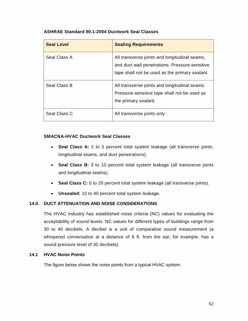
ASHRAE Standard 90.1-2004 Ductwork Seal Classes
Seal Level Sealing Requirements
Seal Class A All transverse joints and longitudinal seams,
and duct wall penetrations. Pressure-sensitive
tape shall not be used as the primary sealant.
Seal Class B All transverse joints and longitudinal seams.
Pressure-sensitive tape shall not be used as
the primary sealant.
Seal Class C All transverse joints only
SMACNA-HVAC Ductwork Seal Classes
• Seal Class A: 2 to 5 percent total system leakage (all transverse joints,
longitudinal seams, and duct penetrations).
• Seal Class B: 3 to 10 percent total system leakage (all transverse joints
and longitudinal seams).
• Seal Class C: 5 to 20 percent total system leakage (all transverse joints).
• Unsealed: 10 to 40 percent total system leakage.
14.0. DUCT ATTENUATION AND NOISE CONSIDERATIONS
The HVAC industry has established noise criteria (NC) values for evaluating the
acceptability of sound levels. NC values for different types of buildings range from
30 to 40 decibels. A decibel is a unit of comparative sound measurement (a
whispered conversation at a distance of 6 ft. from the ear, for example, has a
sound pressure level of 30 decibels).
14.1 HVAC Noise Points
The figure below shows the noise points from a typical HVAC system.
62

The major source of noise in air conditioning systems is due to air velocity as well as
the noise from fan. The 5 distinct paths of noise are:
1. Duct borne noise: It is caused by the flow of air and directly dependent on
the velocity of air.
2. Radiated equipment noise: It is caused by vibration of equipment and
inherent sound pressure of the equipment.
3. Break-in noise: It is radiated equipment noise that enters the ductwork and
propagates down the duct system.
4. Break-out noise: It transmits through the wall of the duct.
5. Terminal end noise: It is caused by the air flows at the terminal devices such
as diffuser or register.
14.2 Acoustical Analysis of a Ductwork System
Noise due to air is roughly proportional to the 5th power of the fan speed. If the speed
of a fan is reduced by 10%, the db will be reduced by 2 dB. If the fan speed is
reduced by 20% and 30%, it will yield a noise reduction of 5 dB and 8 dB,
respectively.
Based on the aforementioned analysis, the following recommendations are made:
63

Duct borne Noise:
1. Keep air velocity low and liberally size the ducts. The air velocity in the main
duct should be limited to 1,500 fpm and the velocity through the branch ducts
should be less than 800 fpm.
2. Select the fan at maximum efficiency point.
3. All VAV installations must have variable frequency drives.
4. The ductwork must be routed, fabricated and supported in accordance with
SMACNA guidelines.
Radiated Equipment Noise:
1. Use vibration isolators between the equipment and the building structure.
Common materials used as vibration isolators are rubber, cork, various types
of steel springs, and glass fiber pads.
2. Use flexible fabric connections between the fan and duct.
3. Avoid locating the HVAC unit in a space immediately adjacent to the occupied
space.
4. Acoustically insulate the mechanical room walls and ceilings with fiber
insulation mounted on wooden battens. The insulation shall be clad with
perforated Aluminum sheet of 36 gauge.
Duct Break-In and Break-Out Noise
1. Ensure low air flow velocity. The air velocity in the main duct and branch duct
should be limited to 1,500 fpm and 800 fpm, respectively.
2. Ensure ducts do not vibrate. Ducts can be made stiffer by adding external
bracing and/or adding damping (spray on or self-adhesive compounds).
3. Avoid abrupt changes in duct cross-sections; most straight ductwork naturally
attenuates noise and provides smooth transitional duct branches, take offs,
and bends.
4. Fitting (such as elbows and transitions) should not be placed closer than 3 to 6
duct diameters downstream from a fan and duct transitions, particularly at the
unit inlet and discharge openings - 15° maximum.
5. Insulate the duct with Rockwool or Glasswool to damp duct breakout noise.
64
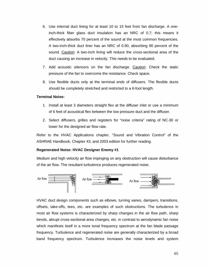
6. Use internal duct lining for at least 10 to 15 feet from fan discharge. A one-
inch-thick fiber glass duct insulation has an NRC of 0.7; this means it
effectively absorbs 70 percent of the sound at the most common frequencies.
A two-inch-thick duct liner has an NRC of 0.90, absorbing 90 percent of the
sound. Caution: A two-inch lining will reduce the cross-sectional area of the
duct causing an increase in velocity. This needs to be evaluated.
7. Add acoustic silencers on the fan discharge. Caution: Check the static
pressure of the fan to overcome the resistance. Check space.
8. Use flexible ducts only at the terminal ends of diffusers. The flexible ducts
should be completely stretched and restricted to a 6-foot length.
Terminal Noise:
1. Install at least 3 diameters straight flex at the diffuser inlet or use a minimum
of 6 feet of acoustical flex between the low pressure duct and the diffuser.
2. Select diffusers, grilles and registers for “noise criteria” rating of NC-30 or
lower for the designed air flow rate.
Refer to the HVAC Applications chapter, "Sound and Vibration Control" of the
ASHRAE Handbook, Chapter 43, and 2003 edition for further reading.
Regenerated Noise: HVAC Designer Enemy #1
Medium and high velocity air flow impinging on any obstruction will cause disturbance
of the air flow. The resultant turbulence produces regenerated noise.
HVAC duct design components such as elbows, turning vanes, dampers, transitions,
offsets, take-offs, tees, etc. are examples of such obstructions. The turbulence in
most air flow systems is characterized by sharp changes in the air flow path, sharp
bends, abrupt cross-sectional area changes, etc. in contrast to aerodynamic fan noise
which manifests itself in a more tonal frequency spectrum at the fan blade passage
frequency. Turbulence and regenerated noise are generally characterized by a broad
band frequency spectrum. Turbulence increases the noise levels and system
65
operating costs. Regenerated noise can be minimized by ensuring smooth air flow
conditions. SMACNA duct design and construction guidelines should be incorporated
in all job specifications and drawings. The SMACNA guidelines also outline optimal
duct silencer locations and guidelines for centrifugal fan installations (distances for
placement of duct fittings).
15.0. DUCTWORK TESTING & SYSTEM PERFORMANCE
Air testing and balancing is a process that measures and adjusts the supply air
distribution of a given HVAC system. The purpose of testing and balancing an
HVAC system is to supply each conditioned zone with the precise amount of
supply air required to offset a given heat gain (or loss).This process is typically
performed after an HVAC system has been installed. The amount of air flow into
each zone is determined from the mechanical design plans. However, air testing
and balancing is also performed in response to certain cases of occupant thermal
discomfort. If occupant thermal discomfort exists in a building with a properly sized
and balanced HVAC system, fine tuning adjustments to supply registers may be
necessary to satisfy all occupants. The following testing requirements are
recommended:
1. Room-by-room air flows are correct;
2. Total supply is as designed;
3. Total return + exhaust = total supply;
4. Ducts, plenum, and air handler are tight; and
5. Static pressure is correct.
15.1 Balancing the System
Balancing a system involves the following steps:
1. Inspect the complete system; locate all ducts, openings, and dampers.
2. Open all dampers in the ducts and at the grilles.
3. Check the velocities at each outlet.
4. Measure the "free" grille area.
5. Calculate the air flow volume at each outlet.
66
6. Total the cubic feet/minute.
7. Determine the floor areas of each room. Add to determine total area.
8. Determine the cfm for each room. The area of the room divided by the
total floor area multiplied by the total cfm equals cfm for the room.
9. Adjust duct dampers and grille dampers to obtain these values.
10. Recheck all outlet grilles. In some cases, it may be necessary to
overcome excess duct resistance by installing an air duct booster.
These are fans used to increase air flow when a duct is too small, too
long, or has too many elbows.
15.2 Testing Methods and Equipment
Duct testing is the process of using calibrated mechanical equipment to measure the
amount of air flow that is lost through the duct system when it is at normal operating
pressure. While some joints or seams may have only small leaks, other sections may
be completely disconnected. Duct testing can indicate the relative leakiness of the
ducts and help determine whether the duct system should be sealed, repaired, or
renovated.
There are two main methods of testing:
1. The pressurization subtraction method utilizes a pressurization unit (i.e. a high
powered fan set up in a doorway and connected to pressure gauges) to
pressurize first the entire space that is heated and/or cooled and then the
same space with the duct system blocked off. This method is less accurate
than the duct testing method.
2. The duct testing method uses a calibrated fan that gently pressurizes the
ducts and measures the air flow through the ducts to indicate total leakage.
The duct tester consists of a portable fan, with calibrated digital pressure
gauges, that is connected at the blower compartment of the air handler, or
attached to the main return grill. The entire duct registers and grills are
temporarily sealed, and the duct tester fan is turned on to pressurize the
system. The fan pressure is read from the gauges and converted to an
equivalent duct leakage rate in cubic feet per minute (cfm). If the amount of air
loss falls outside acceptable limits, sealing will be required to correct the
67

condition. This method of testing is preferred because it measures low air flow
accurately, and simulates what takes place under normal operating conditions.
15.3 Air Flow Measurement Instruments
Anemometer: The anemometer is a device used to measure the velocity of air
travelling through a duct or grille. Readings are measured in feet per minute (fpm).
Air flow is measured in cfm, therefore:
Air Flow (cfm) = Velocity (fpm) x Area (ft2)
For example, if the mean velocity in a rectangular duct 12” x 24” is 1,000 fpm, the
volume flow rate is 12 x 24 x 1,000/144 = 2,000 cfm.
There are three (3) type of anemometer:
a. Hotwire Anemometer: This has a probe consisting of a very fine short
length of wire (or small thermistor bead) attached to the end of a supporting
tube. The wire is heated electrically, and measurements are made of the
heat dissipated by the wire. The rate of heat dissipation is directly related
to the velocity of the air passing the wire.
b. Rotating Vane Anemometer: This consists of a disc of angled vanes
attached to a rotating spindle and is usually mounted within a protective
ring and supporting bracket. The speed at which the vane assembly rotates
is a measure of the air velocity acting upon it. This speed may be sensed
either electronically or by a counter mechanism.
c. Ultrasonic Anemometer: This takes clean air and gas glow velocity
measurements with a "mini sensor". Using three energized "posts", sound
waves are transmitted sequentially 3,849 times every second. The time
taken for sound to travel from one post to another and for a wave to return
over the same precise distance is measured. By using the speed of sound,
at 340.3 m/sec in standard air as a "carrier", the true velocity can be
calculated with 100% certainty and repeatability. Any changes in ambient
temperature, barometric pressure, RH and gas density conditions are
rendered irrelevant for use in mixed air/inert gas density situations, without
any need for corrections, re-calibration or complex calculations.
68

Manometer: The manometer is a device used to measure relatively low pressures
or more commonly, pressure devices.
Manometers are made in two (2) different styles. Both are used to measure the
pressure difference across an object, e.g. filter, coil and fan:
1. The U-Tube Manometer. In order to read the amount of pressure applied,
read the value corresponding to the fluid level on one side of the tube and
double it.
2. Inclined Manometer. In order to read the amount of pressure applied, read
the value according to the fluid level in the tube.
The Pitot-Tube: The pitot-tube is a device that is usually used together with an
inclined manometer to measure the static pressure, total pressure and velocity
pressure within a ducted system. The pitot tube assembly includes a static
pressure probe and a total pressure probe. A total pressure probe, aligned into the
air flow, senses the duct velocity pressure and the static pressure, which equals
the total pressure. A static pressure probe aligned at a right angle to the air flow
senses only the static pressure. The difference between the total pressure reading
and the static pressure reading is the velocity pressure.
15.4 Determining Air Flow at Grilles
The rotating vane anemometer is often used for measuring the velocity at inlet
grilles and extract openings. If the grille has directional louvers, these should be
set at right angles before taking readings.
69
Measurement of air velocity should be made between the blades at a number of
positions. The effective free outlet area of the grille can be found from the relevant
manufacturer’s data or estimated from the unobstructed flow area of the grille.
To determine the volume flow, the measurement instrument should be evenly
traversed across the entire grille face to determine an arithmetic mean value of the
air velocity. The volume flow is then:
Q = Aeff x Vmean x f
Where,
• Q = volume flow (cfm)
• Aeff = effective free outlet area of the grille (ft2)
• Vmean = mean velocity (fpm)
• f = correction factor for obstruction by the measuring instrument (for
rotating vane anemometer, f = 1.3 to 1.9.
15.5 Determining Air Flow in Ducts
The pitot tube with the manometer is generally used for measuring the velocity in
ducts. If you connect the total pressure probe to the HIGH port on a differential
pressure sensor and the static pressure probe to the LOW port on the differential
pressure sensor, then the sensor’s output will be the velocity pressure.
The readings from the manometer are velocity pressure (VP) in inches of water
column, and not in velocity (fpm). Therefore, it is necessary to convert velocity
pressure to velocity, in feet per minute (fpm), using the following equation:
Velocity (fpm) = 4005 x (VP) ½
where,
• V = Flow Velocity in feet per minute, (fpm)
• VP = The Velocity Pressure measured by the pressure sensor, (in-wc)
After obtaining the flow velocity from the equation above, the value is now
multiplied by the duct cross-sectional area to determine the air flow in cfm.
There are two different equations for determining the duct cross-sectional area,
one for round ducts and one for square or rectangular ducts.
70
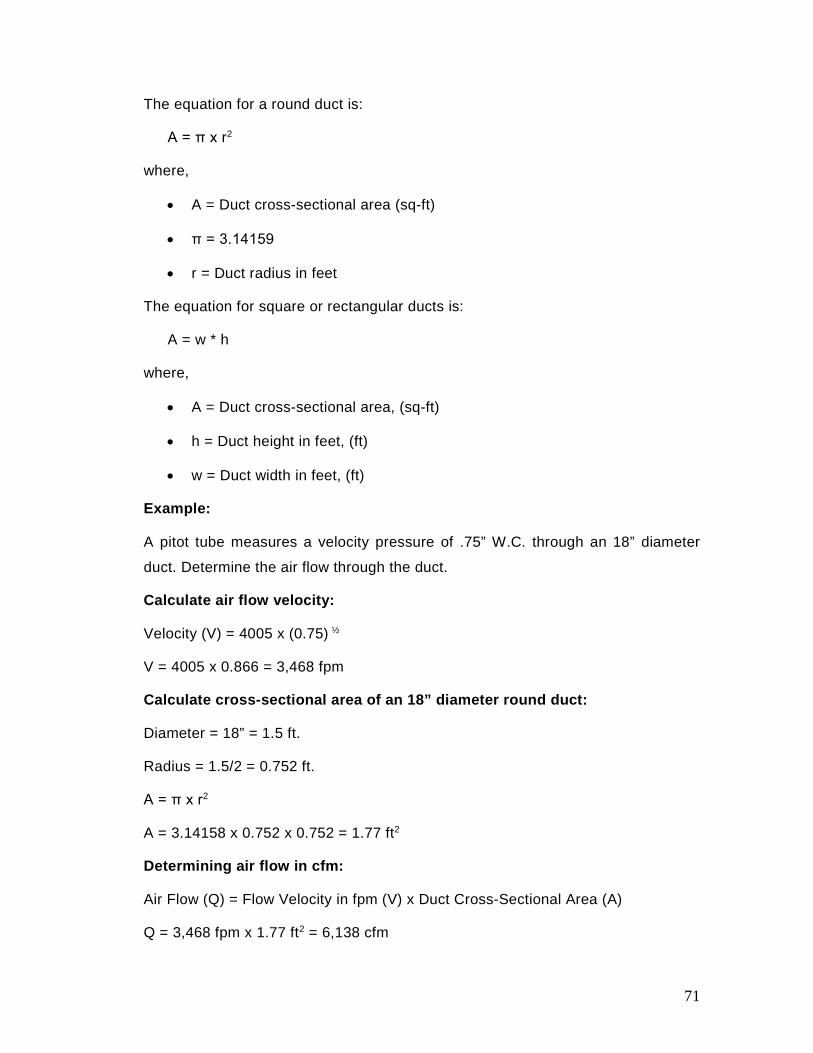
The equation for a round duct is:
A = π x r2
where,
• A = Duct cross-sectional area (sq-ft)
• π = 3.14159
• r = Duct radius in feet
The equation for square or rectangular ducts is:
A = w * h
where,
• A = Duct cross-sectional area, (sq-ft)
• h = Duct height in feet, (ft)
• w = Duct width in feet, (ft)
Example:
A pitot tube measures a velocity pressure of .75” W.C. through an 18” diameter
duct. Determine the air flow through the duct.
Calculate air flow velocity:
Velocity (V) = 4005 x (0.75) ½
V = 4005 x 0.866 = 3,468 fpm
Calculate cross-sectional area of an 18” diameter round duct:
Diameter = 18” = 1.5 ft.
Radius = 1.5/2 = 0.752 ft.
A = π x r2
A = 3.14158 x 0.752 x 0.752 = 1.77 ft2
Determining air flow in cfm:
Air Flow (Q) = Flow Velocity in fpm (V) x Duct Cross-Sectional Area (A)
Q = 3,468 fpm x 1.77 ft2 = 6,138 cfm
71
15.6 Provisions during Design for Testing, Adjusting and Balancing
It is important for system air to get to the occupied space with minimal losses
caused from leakage and resistance, with proper mixing of air, and without
temperature changes from heat gains or losses. Also important are the noise,
draft, and efficiency with which air is delivered. The means to meet these
requirements are the proper design of ductwork and outlets.
The designer should give special attention to the balancing and adjusting process
during the design. It is necessary that the balancing capability be designed into
the system initially. Below are some considerations to make when designing duct
systems.
1. Sufficient lengths of straight duct must be provided in an accessible area to
allow the TAB personnel to perform their function properly. This also
applies in TAB work of the critical branches of the distribution system.
2. Mixing boxes should be located so the discharge ductwork will minimize air
turbulence and stratification.
3. Ductwork to and from air conditioning equipment should be designed
carefully so stratified air may be mixed properly before entering branch
ducts or equipment.
4. Adequate size access doors should be installed within a normal working
distance of all volume dampers, fire dampers, pressure reducing valves,
reheat coils, mixing boxes, blenders, constant volume regulators, etc. that
require adjustments within the ductwork.
5. Manually operated, opposed blade or single blade, quadrant-type volume
dampers should be installed in each branch duct take-off after leaving the
main duct to control the amount of air entering or leaving the branch.
6. Do not use extractors at branch or main duct take-offs because they can
cause turbulence in the main trunk duct thereby increasing the system total
pressure, and affecting the performance of other branch outlets
downstream. Extractors are principally used to divert air to branch ducts.
72
16.0. DUCT CLEANING
There is also the question of when duct cleaning should be done, and how the job
could be validated. Duct cleaning may be warranted in any of the following situations:
• There is substantial evidence of visible mold growth inside the hard surface of
ducts or on other components of the heating and cooling system. Get
laboratory analysis carried out for the sample before taking the decision.
• If you have insulated air ducts and the insulation gets wet or moldy, it cannot
be effectively cleaned and should be removed and replaced.
• Ducts are infested with vermin, e.g. (rodents or insects).
• Ducts are clogged with excessive amounts of dust or debris, whereby particles
are actually released into the home from the supply registers.
According to the Environmental Protection Agency (EPA), duct cleaning has never
been shown to actually prevent health problems. Moreover, studies do not
conclusively demonstrate that particle levels in homes increase because of dirty air
ducts. This is because much of the dirt in the air ducts adheres to duct surfaces and
does not necessarily enter the living space. It is important to keep in mind that dirty
air ducts are only one of many possible sources of particles that are present in
homes. Pollutants that enter the home both from the outdoors, as well as from indoor
activities such as cooking, cleaning, smoking, or just moving around, can cause
greater exposure to contaminants than dirty air ducts. Moreover, there is no evidence
that a light amount of household dust or other particulate matter in air ducts poses
any risk to your health.
In 1989, the National Air Duct Cleaners Association (NADCA) was formed by
members of the duct cleaning industry. This organization adopted a standard in 1992
entitled: NADCA Standard 1992-01, Mechanical Cleaning of Non-Porous Air
Conveyance System Components. This standard provides performance requirements
and evaluation criteria for the mechanical cleaning of non-porous ductwork, fans,
coils, and other non-porous components of commercial and residential air
conveyance systems.
73
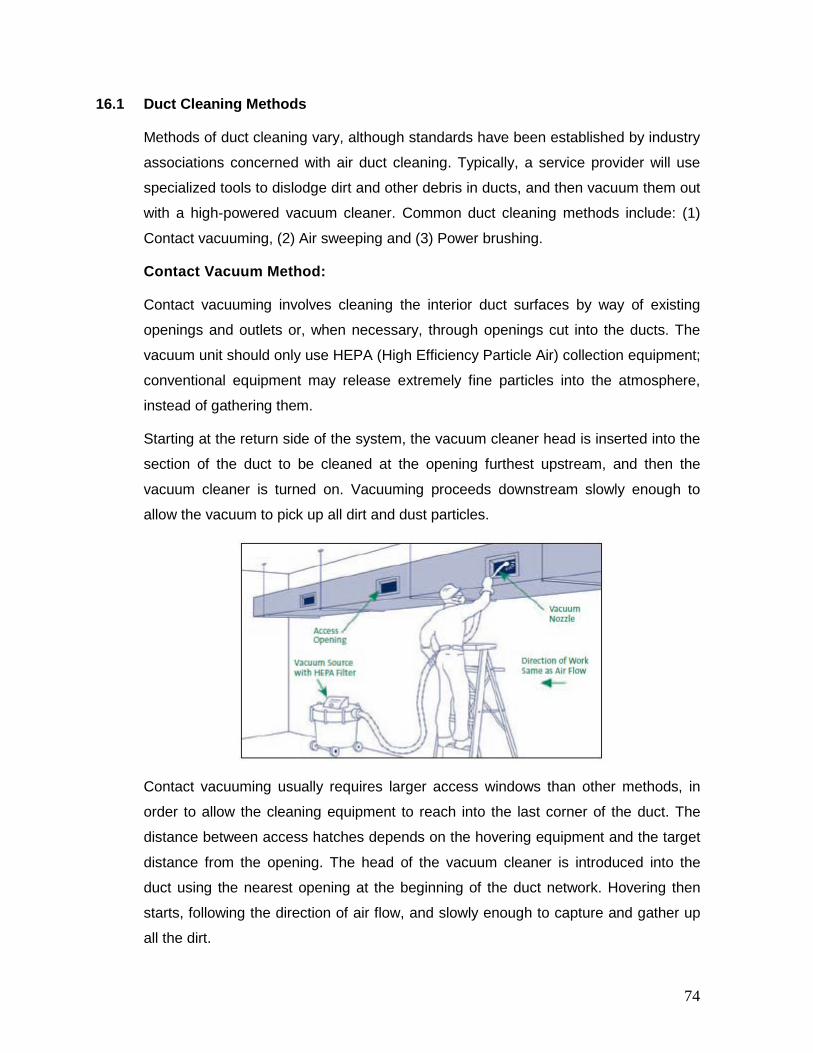
16.1 Duct Cleaning Methods
Methods of duct cleaning vary, although standards have been established by industry
associations concerned with air duct cleaning. Typically, a service provider will use
specialized tools to dislodge dirt and other debris in ducts, and then vacuum them out
with a high-powered vacuum cleaner. Common duct cleaning methods include: (1)
Contact vacuuming, (2) Air sweeping and (3) Power brushing.
Contact Vacuum Method:
Contact vacuuming involves cleaning the interior duct surfaces by way of existing
openings and outlets or, when necessary, through openings cut into the ducts. The
vacuum unit should only use HEPA (High Efficiency Particle Air) collection equipment;
conventional equipment may release extremely fine particles into the atmosphere,
instead of gathering them.
Starting at the return side of the system, the vacuum cleaner head is inserted into the
section of the duct to be cleaned at the opening furthest upstream, and then the
vacuum cleaner is turned on. Vacuuming proceeds downstream slowly enough to
allow the vacuum to pick up all dirt and dust particles.
Contact vacuuming usually requires larger access windows than other methods, in
order to allow the cleaning equipment to reach into the last corner of the duct. The
distance between access hatches depends on the hovering equipment and the target
distance from the opening. The head of the vacuum cleaner is introduced into the
duct using the nearest opening at the beginning of the duct network. Hovering then
starts, following the direction of air flow, and slowly enough to capture and gather up
all the dirt.
74

Air Sweep Method:
In the air sweep or air washing method, a vacuum collection unit is connected to the
downstream end of the duct section. The vacuum unit should use HEPA filtering, if it
is exhausting into an occupied space. The isolated section of duct being cleaned
should be subjected to a minimum of 1" negative air pressure to draw loosened
materials into the vacuum collection system. Take care not to collapse the duct.
Compressed air is then introduced into the duct through a hose equipped with a
skipper nozzle. This nozzle is propelled by the compressed air along the inside of the
duct. For the air washing method to be effective, the compressed air source should be
able to produce between 160 and 200 psi air pressure and should have a 20-gallon
receiver tank. This method is most effective in cleaning ductwork no larger than 24" ×
24" inside dimensions. Inspection of each duct section and related components is
performed to determine whether the duct is clean.
Power (Mechanical) Brushing Method:
In the power brushing method, a vacuum collection unit is connected to the duct in the
same way as with the air sweep method. Pneumatic or electric rotary brushes are
used to dislodge dirt and dust particles, which become airborne and are then drawn
into the vacuum unit. Brushing operations will usually require larger access openings
than the previous method. Nevertheless, fewer openings are needed. Certain types of
mechanical brushes can reach up to 24 ft. in both directions.
75

Inspection of each duct section and related components is performed to determine if
the duct is clean. When the section of duct is clean, the brush is removed from the
duct and inserted through the next opening, where the process continues.
Other Cleaning Variations
The service provider may propose applying chemical biocides, designed to kill
microbiological contaminants, to the inside of the duct work and to other system
components. Some service providers may also suggest applying chemical treatments
(sealants) to encapsulate or cover the inside surfaces of the air ducts and equipment
housings because they believe it will control mold growth or prevent the release of dirt
particles or fibers from ducts. These practices have yet to be fully researched and you
should be fully informed before deciding to permit the use of biocides or chemical
treatments in your air ducts.
16.2 Coordination between Design Specialties
The process of design review includes a spot check to verify that the mechanical
design is coordinated with the electrical, structural, and architectural design. Many
of the following coordination checks will ensure energy efficiency in addition to
verifying systems integration:
1. Is the structural support adequate in the areas where mechanical
equipment will be located?
2. Do the architectural and structural details provide the necessary sound
isolation and moisture protection in the mechanical areas?
3. Are the intake and exhaust penetrations through the walls adequately sized
to prevent high pressure drops and moisture penetrations?
76

4. Are chase sizes large enough to allow adequately sized ductwork?
5. Are the structural clearances around chases and other areas with large
duct and piping mains sufficient to allow the systems to be installed without
high pressure drops?
6. Is there sufficient space above the ceiling and below the structure to allow
the necessary mechanical system to be routed in conjunction with the
electrical, plumbing and specialty systems without an excessive number of
offsets and/or restricted duct sizes?
7. Have general rules been established for routing ducts, pipes, conduits and
specialty systems through the ceiling cavity? If so, do they meet the
requirements of the mechanical systems?
8. Is there a suitable access route to allow worn-out equipment to be removed
and new equipment to be installed? Does this route contain adequate
structural strength to support the equipment that might be moved through
it?
9. Are the electrical service requirements coordinated with the requirements
of the mechanical systems in terms of voltage, capacity, reliability, and
source? An air-handling system that has its fans powered by the
emergency system, its Direct Digital Control (DDC) controllers powered by
an Uninterruptible Power Supply, with an interlock circuit on normal power,
may experience a few problems when there is a momentary power surge
on the utility line.
10. If the project will use variable speed drives, who will specify them? If the
drives require isolation transformers or line reactors, who is responsible for
sizing and specifying them?
11. Have the motor horsepower requirements changed since design
development?
12. Has the type of starter that will be used for large machinery been
coordinated with the electrical designer? Often, changing the type of starter
or the voltage that is used to serve a large motor can improve electrical
system performance and reduce first costs.
77
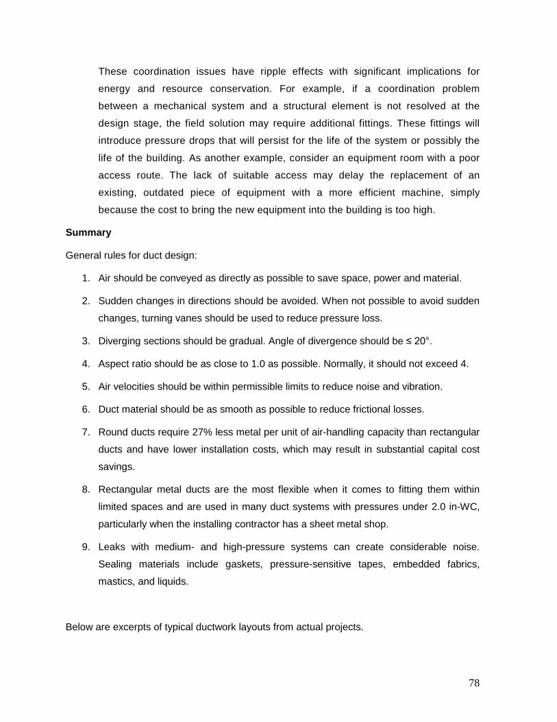
These coordination issues have ripple effects with significant implications for
energy and resource conservation. For example, if a coordination problem
between a mechanical system and a structural element is not resolved at the
design stage, the field solution may require additional fittings. These fittings will
introduce pressure drops that will persist for the life of the system or possibly the
life of the building. As another example, consider an equipment room with a poor
access route. The lack of suitable access may delay the replacement of an
existing, outdated piece of equipment with a more efficient machine, simply
because the cost to bring the new equipment into the building is too high.
Summary
General rules for duct design:
1. Air should be conveyed as directly as possible to save space, power and material.
2. Sudden changes in directions should be avoided. When not possible to avoid sudden
changes, turning vanes should be used to reduce pressure loss.
3. Diverging sections should be gradual. Angle of divergence should be ≤ 20°.
4. Aspect ratio should be as close to 1.0 as possible. Normally, it should not exceed 4.
5. Air velocities should be within permissible limits to reduce noise and vibration.
6. Duct material should be as smooth as possible to reduce frictional losses.
7. Round ducts require 27% less metal per unit of air-handling capacity than rectangular
ducts and have lower installation costs, which may result in substantial capital cost
savings.
8. Rectangular metal ducts are the most flexible when it comes to fitting them within
limited spaces and are used in many duct systems with pressures under 2.0 in-WC,
particularly when the installing contractor has a sheet metal shop.
9. Leaks with medium- and high-pressure systems can create considerable noise.
Sealing materials include gaskets, pressure-sensitive tapes, embedded fabrics,
mastics, and liquids.
Below are excerpts of typical ductwork layouts from actual projects.
78
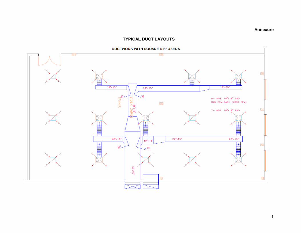
Annexure
TYPICAL DUCT LAYOUTS
1

2
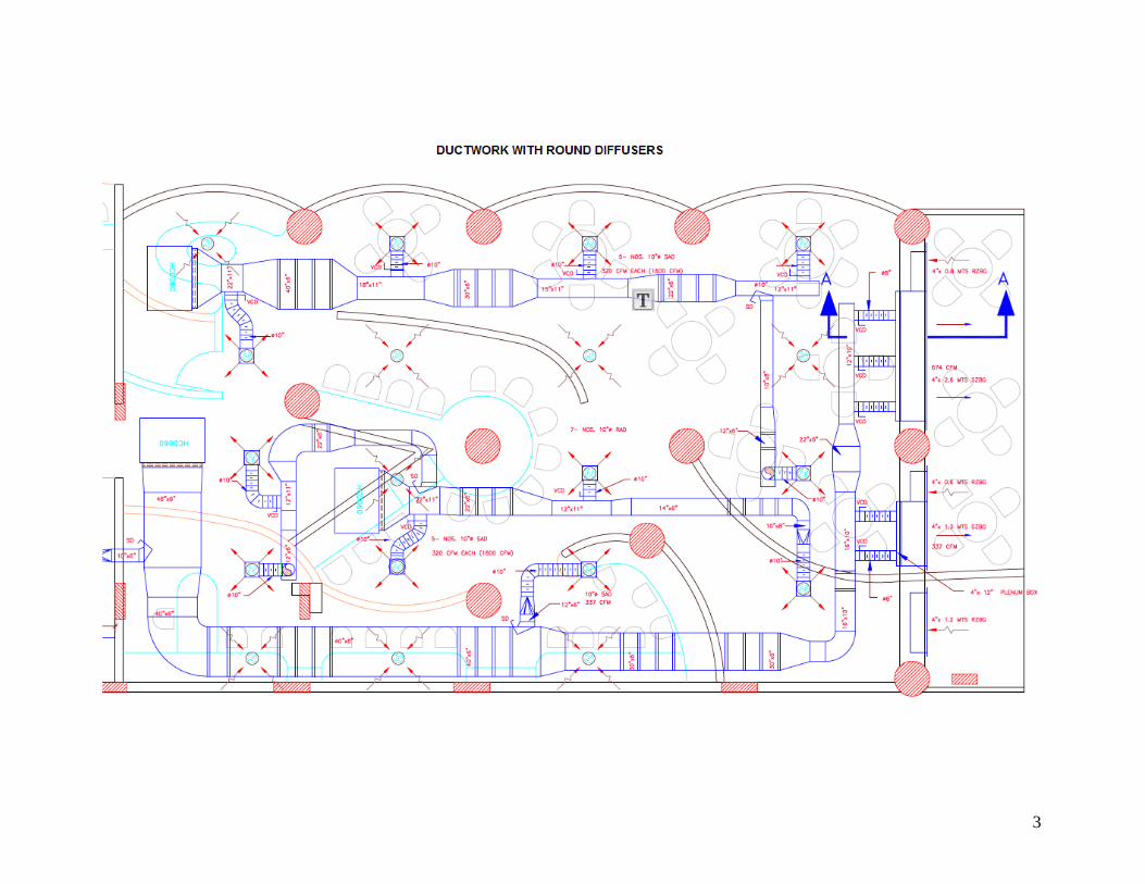
3

4

5
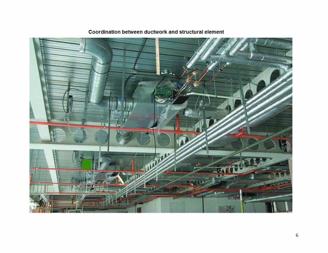
6
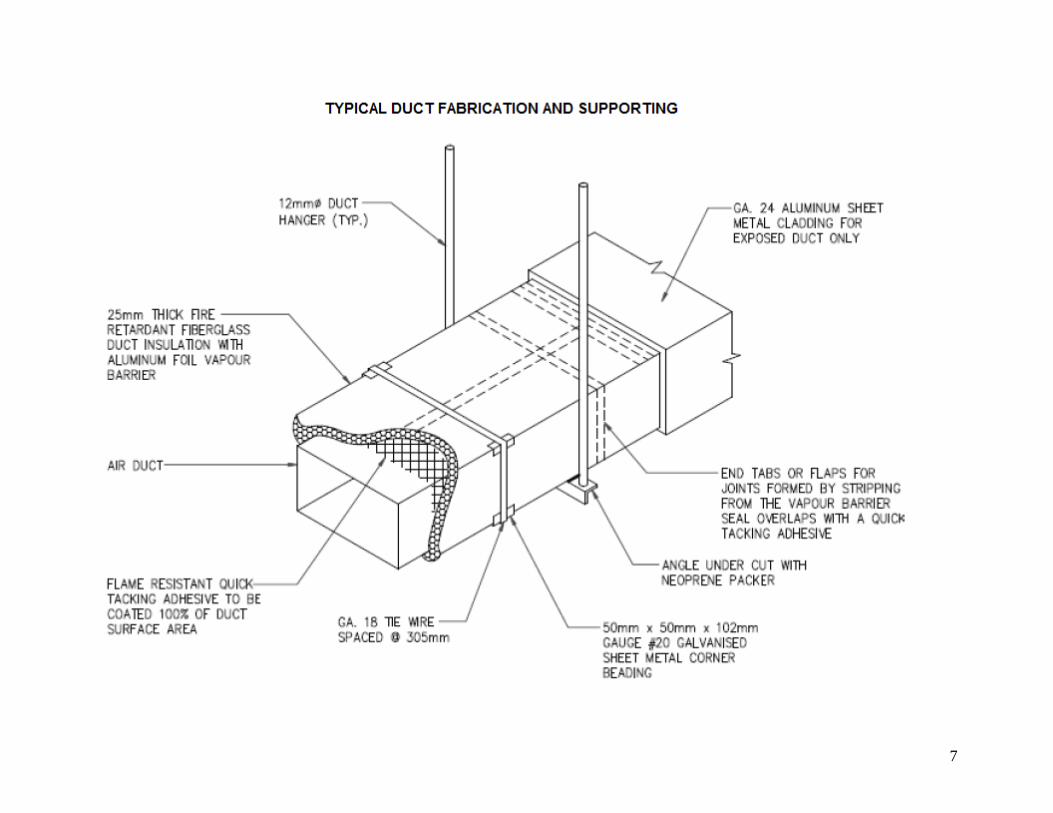
7
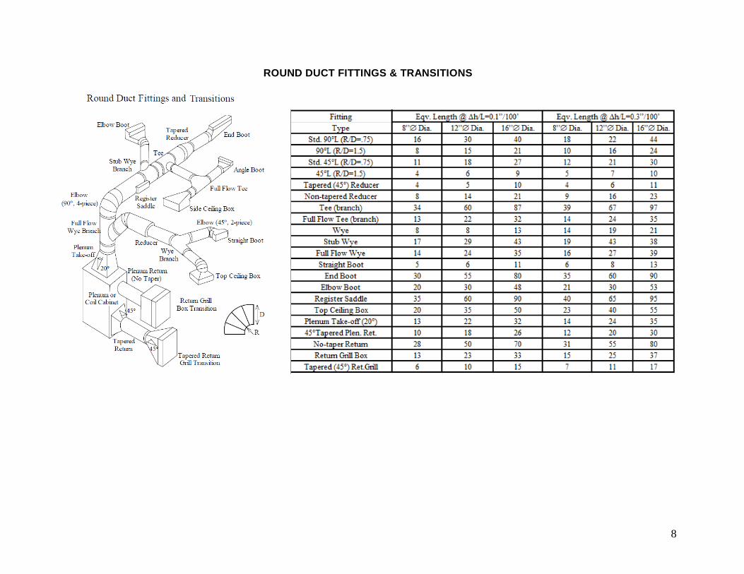
ROUND DUCT FITTINGS & TRANSITIONS
8
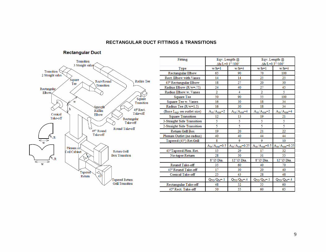
RECTANGULAR DUCT FITTINGS & TRANSITIONS
9
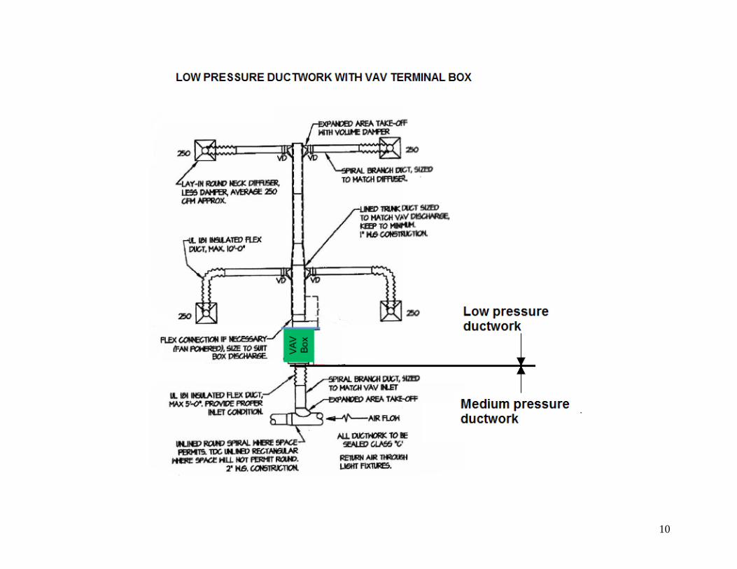
10
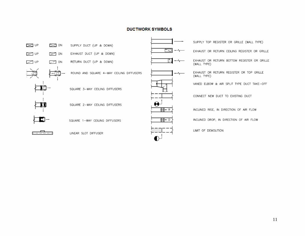
11

12