HVAC Design Experimentchem.engr.utc.edu/Student-files/x-2011-Fa/4350/HVAC-attachment... · Outline...
22
HVAC Design Experiment The University of Tennessee at Chattanooga ENCH 4350L Brad C Newman
Transcript of HVAC Design Experimentchem.engr.utc.edu/Student-files/x-2011-Fa/4350/HVAC-attachment... · Outline...

HVAC Design Experiment
The University of Tennessee at Chattanooga
ENCH 4350L
Brad C Newman

Outline• Introduction
-Background
-Goals
-Design Approach
-HVAC Theory
• Experiment
– Equipment
– Measurements
• Analysis
– Calculations
– Specification
• Results
– HVAC Specifications
• Conclusions
• Comments/Questions
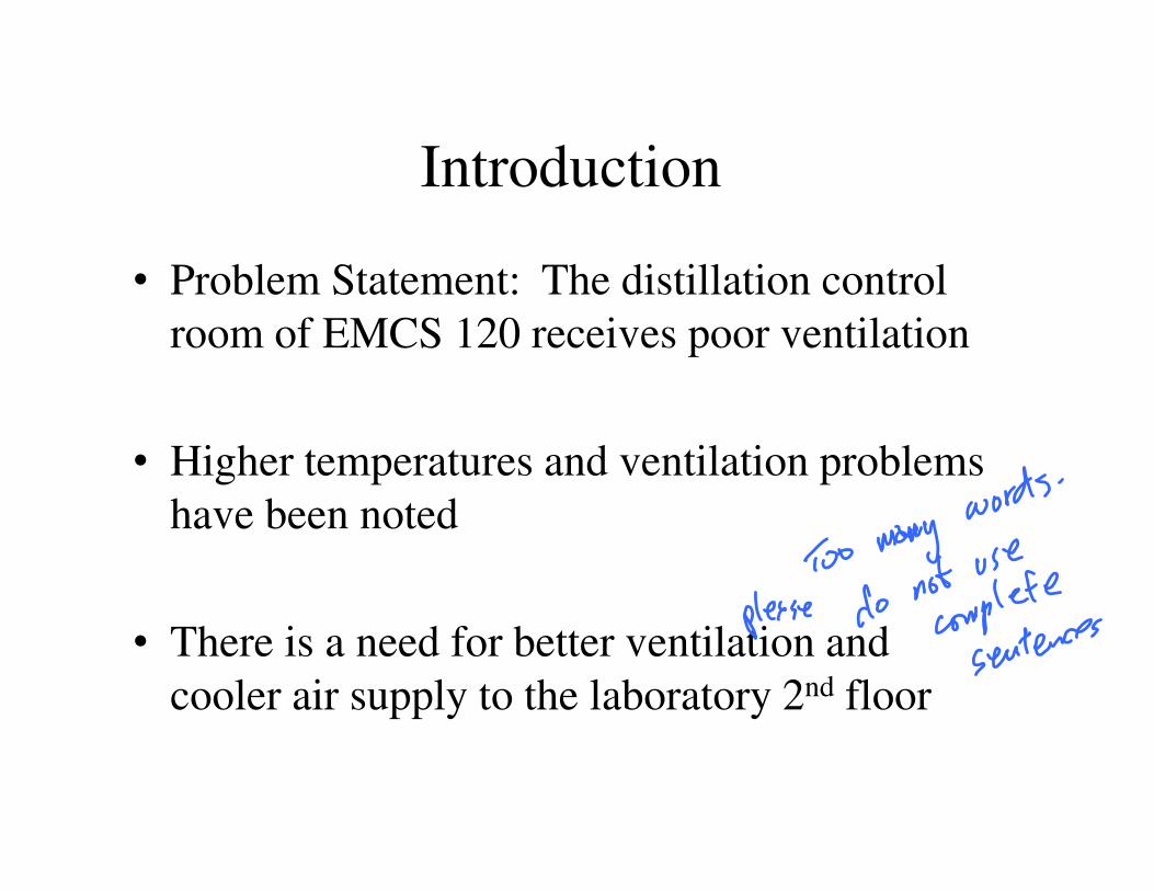
Introduction
• Problem Statement: The distillation control
room of EMCS 120 receives poor ventilation
• Higher temperatures and ventilation problems
have been noted
• There is a need for better ventilation and
cooler air supply to the laboratory 2nd floor

Experiment Goals
• Design an HVAC system to increase ventilation and
lowering control room air temperature
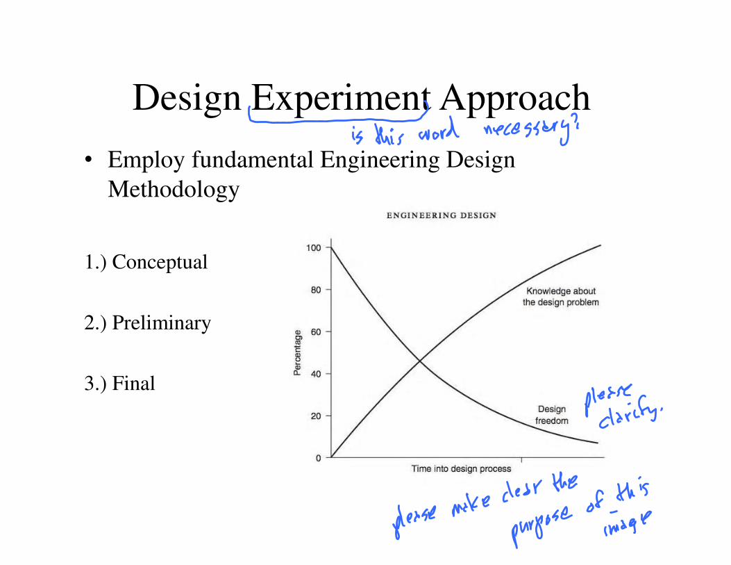
Design Experiment Approach
• Employ fundamental Engineering Design
Methodology
1.) Conceptual
2.) Preliminary
3.) Final

HVAC Theory
• Process by which fresh air is introduced, and
contaminated air is removed
• Two Design Essentials:
1.) Provision of cool fresh air to occupants
2.) Change air in room to remove contaminates

Theory (cont’d)
• Starting point: Standard air ventilation rates
1.) Air change per hour (ACH)
ACH = Q/Vroom (cfm/cf)
2.) Fresh air supply rate per person (ACP)
ACP = Q/person/time (cfm/person/min)

Professional HVAC Design Standards
• ASHRAE & IMC: Acceptable indoor air quality
– Standard 62-2001 and 62.1-2004
IMC ASHRAE
Educational Classroom 15 15
Public Assembly Facility 15 5
General Office Space 20 17
Hotel, motel, and resort lobbies 15 10
Occupancy CategoryAir Exchange Rate (Cfm/person)
Table 1: Typical Air Exchange Standards

Theory – Humidity Considerations
• Relative Humidity: Water-holding capacity of air
• Temperature Dependence:
• HVAC perspective: Humidity = Undesirable

Relative Humidity Sub-Experiment
• Temperature and Humidity Measurements
taken in 1st and 5th floor stairwell heights
• Comparison
• Effect of rising less-dense hot vs. dense cooler
air distribution

Experiment - Deliverables
• Use bottom 1st floor lower temperatures to supply ventilation to 2nd floor
• Measure control room and design dimensions
• Measure necessary ventilation design variables
• Apply HVAC theory and standards to measured data to develop a preliminary design


Experiment - Equipment

Experiment - Data
∆T = 5.3 °F
• Control Room Volume: Vroom = L*W*H = 4252Ft3
Avg. Temp. (°F)
Avg. Relative H (%)
Floor 1 (Inflow): Average T and HR
66.3
44.2
Avg. Temp. (°F)
Avg. Relative H (%)
71.6
38.37
Floor 2 (Outflow): Average T and HR

Experiment – Data Representaiont
• (Temperature and RH plot against time)

HVAC Design Analysis
• Determination of design flow rate
Q = ACH*Vroom
= (10/hr)(4252Ft3)/60min
= 1063 Ft3/min
• Required air velocity
V = V*A

Analysis (cont’d)

HVAC Design Results
• Design requirements
-Input power
-Fan Selection: centrifugal /squirrel cage
• Design Architecture
-Dimensions, Physical layout
• Embodiment
-Ductwork
-Acoustic analysis

Further Needed Experiments

Applications in Chemical Engineering

Conclusions

Questions/Comments