
HV POWER CABLES INSTALLED IN MULTI PURPOSE · PDF fileReturn to Session HV POWER CABLES...
5
Return to Session HV POWER CABLES INSTALLED IN MULTI PURPOSE TUNNELS, A CHALLENGEABLE OPTION! Wim BOONE, KEMA Consulting (Netherlands), [email protected] Frank DE WILD, KEMA Consulting (Netherlands), [email protected] ABSTRACT If a HV power cable is installed in a tunnel, many aspects are different compared with the classical ways of cable installation. In case of a multi-purpose tunnel an analysis has to be performed to specify the different mutual influences under normal operating and under failure conditions. The influences dealt with in this paper are the thermal aspects, magnetic fields, induced voltages in nearby infrastructures, failure risks and the procedures for inspection, maintenance, alarm detection et cetera. These aspects will be discussed based on recent practical experience and it will be demonstrated that power cables can be effectively installed in multi-purpose tunnels. KEYWORDS Power cable, installation, multi purpose tunnel, forced air ventilation, magnetic field, mutual influence, risk analysis. 1. INTRODUCTION Cables can be installed in several ways: direct burial, in ducts, in directional drillings and in tunnels [1,2]. Every method has its pro’s and con’s. Quite often methods of installation are historically determined. For instance in some countries direct burial is common practice, in others the duct or conduit system is being used for a long time. A more novel technique like HDD is being selected on careful cost/benefit considerations. The tunnel option to accommodate HV cables is not particularly modern; as for many years this method is being used worldwide. However a tunnel accommodating different systems (multi purpose tunnel), including HV cables is to be considered as an innovative method of installation and is getting more attention. The main reason for this attention is related to the increased pressure from the authorities to exchange “chaos” in the soil by “law and order” in a tunnel (see figure 1) and last but not least to reduce cost by allowing different parties to share costs in one multi purpose tunnel. The main advantages of such a multi purpose tunnel can be briefly summarized as follows: o Efficient use of the soil o Easy accessibility in case of maintenance and repair o Adequate protection against external damage The main disadvantages are: o Mutual impact between different systems o Complicated organizational structure o High costs Figure 1: An orderly multi-purpose tunnel interior with HV cables and different pipes for transporting liquids and gasses. In this paper, based on recent practical experience both in the Netherlands and abroad, the different issues will be dealt with. In particular typical cable issues or cable problems will be considered and will be analyzed to get them under control between acceptable limits: o Thermal aspects o Magnetic fields o Induced voltages o Failure behaviour Finally future developments and conclusions will be given, going in the direction that the multi purpose tunnel is a challengeable option for installing HV cables in the future. 2. SINGLE PURPOSE VERSUS MULTI PURPOSE TUNNELS When power cables are installed in a tunnel with electric cables only, this refers to the situation of a single purpose tunnel. However when a cable is installed in a tunnel together with other systems (gas, chemicals, water, etc.), the cable is part of a so-called multi purpose tunnel, see figure 2 for an impression.
-
Upload
nguyenthuy -
Category
Documents
-
view
257 -
download
1
Transcript of HV POWER CABLES INSTALLED IN MULTI PURPOSE · PDF fileReturn to Session HV POWER CABLES...

Return to Session
HV POWER CABLES INSTALLED IN MULTI PURPOSE TUNNELS, A CHALLENGEABLE OPTION!
Wim BOONE, KEMA Consulting (Netherlands), [email protected] DE WILD, KEMA Consulting (Netherlands), [email protected]
ABSTRACT If a HV power cable is installed in a tunnel, many aspects are different compared with the classical ways of cable installation. In case of a multi-purpose tunnel an analysis has to be performed to specify the different mutual influences under normal operating and under failure conditions. The influences dealt with in this paper are the thermal aspects, magnetic fields, induced voltages in nearby infrastructures, failure risks and the procedures for inspection, maintenance, alarm detection et cetera. These aspects will be discussed based on recent practical experience and it will be demonstrated that power cables can be effectively installed in multi-purpose tunnels.
KEYWORDS Power cable, installation, multi purpose tunnel, forced air ventilation, magnetic field, mutual influence, risk analysis.
1. INTRODUCTION Cables can be installed in several ways: direct burial, in ducts, in directional drillings and in tunnels [1,2]. Every method has its pro’s and con’s. Quite often methods of installation are historically determined. For instance in some countries direct burial is common practice, in others the duct or conduit system is being used for a long time. A more novel technique like HDD is being selected on careful cost/benefit considerations. The tunnel option to accommodate HV cables is not particularly modern; as for many years this method is being used worldwide. However a tunnel accommodating different systems (multi purpose tunnel), including HV cables is to be considered as an innovative method of installation and is getting more attention. The main reason for this attention is related to the increased pressure from the authorities to exchange “chaos” in the soil by “law and order” in a tunnel (see figure 1) and last but not least to reduce cost by allowing different parties to share costs in one multi purpose tunnel. The main advantages of such a multi purpose tunnel can be briefly summarized as follows: o Efficient use of the soil o Easy accessibility in case of maintenance and repair o Adequate protection against external damage The main disadvantages are: o Mutual impact between different systems o Complicated organizational structure o High costs
Figure 1: An orderly multi-purpose tunnel interior with HV cables and different pipes for transporting liquids and gasses. In this paper, based on recent practical experience both in the Netherlands and abroad, the different issues will be dealt with. In particular typical cable issues or cable problems will be considered and will be analyzed to get them under control between acceptable limits: o Thermal aspects o Magnetic fields o Induced voltages o Failure behaviour Finally future developments and conclusions will be given, going in the direction that the multi purpose tunnel is a challengeable option for installing HV cables in the future.
2. SINGLE PURPOSE VERSUS MULTI PURPOSE TUNNELS When power cables are installed in a tunnel with electric cables only, this refers to the situation of a single purpose tunnel. However when a cable is installed in a tunnel together with other systems (gas, chemicals, water, etc.), the cable is part of a so-called multi purpose tunnel, see figure 2 for an impression.

Return to Session
Figure 2: A tunnel cross section showing different utilities and cable circuits in different configurations.
It has already been said, that the reasons for being together with different systems in one tunnel are cost sharing and lack of space, more or less comparable with the well known phenomena of ”car-pooling”. Car-pooling implies obvious lack of mobility, however it saves money and in many countries the travel time will be reduced significantly. In many countries the multi-purpose tunnel is gaining popularity. CIGRE Study Committee B1 launched a few years ago a WG to study the situation in a multi purpose tunnel and to prepare guidelines for proper coexistence between the different parties.
3. RISK ANALYSIS In case of a cable circuit to be installed in a multi purpose tunnel, the mutual risks between cable and other infrastructures have to be evaluated in a proper risk analysis or risk scan, for the following three situations: o During installation o During normal operation o During a failure situation in which cables or other
systems are involved. As criteria for evaluation the well-known TEMA criteria are used: Thermal, Electrical, Mechanical and Ambient. The results of the risk analysis are implemented in a risk management system. In this risk management system, risks and measures to control the risks are correlated. A cost/benefit analysis must proof if proposed measures will be or will be not feasible. As a result of such a risk analysis, carried out for a practical situation in the Netherlands, the following conditions, based on safety and explosion regulations, were set: o The tunnel has to be cooled to control the
temperatureThe tunnel has to be divided in zones with different level of magnetic field stress, accessible to qualified personnel and other persons.
o The calculated induced voltages on other metal structures must be below the specified limits.
o The cables have to be properly fixed to withstand short
circuit forces and to allow thermal expansion. o Safety procedures have to include a proper Monitoring &
Protection system, to detect temperature increase, leakages and smoke in an early phase.
o Maintenance procedures have to be clear and effective to avoid damaging other systems.
o The process of extinguishing of a possible fire needs special attention, as the fire brigade may only go down into the tunnel in case of fire alarm if their safety can be demonstrated.
If these conditions can be fulfilled, the cable installation in the tunnel is considered to be a feasible option and a necessary ATEX certification can be assigned. This certification is assigned under the assumption that systems already present in the tunnel and related aspects like failure behaviour, leak detection, fire behaviour, alarming, maintenance management, are already satisfying the ATEX certification.
4. TYPICAL HV CABLE ASPECTS/ PROBLEMS 4.1 Heat generationA cable system produces heat in the conductor, the dielectric and in the sheath. This heat has to be removed in order to ensure that the tunnel temperature will stay within acceptable limits (10-25ºC for a tunnel accessible for personnel). To evaluate the thermal situation systematically, a dynamic model has to be developed for the situation, with heat sources, thermal resistances and thermal capacitances. See for models references [3,4,5]. By using this model, calculations can be performed to recommend how to control the thermal situation effectively. Although in the past cables have been installed in plastic tubes with flowing water (integral water cooling) [6], the most efficient way is to remove the generated heat in the tunnel by means of a ventilator using the normal available ambient air without any additional cooling. As the available ambient temperature may reach temperatures above the acceptable limits, the ventilator is operated in a periodic time schedule. This calls for a full dynamic thermal model of the tunnel situation. Various cooling regimes have been considered, resulting in the recommendation of cooling day and night, at a low speed of 0.25-0.5 m/s. In figure 3 a practical situation in a tunnel in the NL has been evaluated with a full dynamic model of the situation capable of calculating the effect of periodic ventilation with realistic ambient temperature data. The thermal model used is made specific for this tunnel with its double 150 kV cable circuit, the pipes and materials used in the tunnel, periodic ventilation and the actual ambient temperatures measured by a weather service in the area during the last 50 years. The different scenarios presented in figure 3 correspond to different ventilation regimes (for example ventilating with 1 m/s during night time and with 0.25 m/s during daytime). In the first year of operation, the tunnel temperatures rise slowly. This long-term effect is caused by the heat flowing radially outside the tunnel, and it will continue to increase the tunnel temperature over the years by some degrees. It

Return to Session
Figure 3: The air temperatue inside the tunnel for different periodic ventilation regimes (during daytime different than during nighttime).
Figure 4: A close-up of figure 2. Now the temperature excursions during day and night time can be seen.
can be clearly seen by looking at the top of the blue band in figure 2 extremely left and extremely right. Without the long-term effect, the temperature there would be the same. The importance of the long-term effect of course depends on the ventilation regime, as with increasing ventilation, the heat is increasingly removed axially rather than radially. Figure 4 is a close-up of figure 3. Here it can be seen that the coloured bands of figure 2 actually are daily temperature excursions, caused by a difference in ventilation regime and by a difference in ambient temperature during daytime and during night time.
4.2 Magnetic fieldA cable also produces a magnetic field that has to be calculated to demonstrate that in the area that is accessible for personnel, official limits are not exceeded. For professional personnel and non-professional personnel in the Netherlands respectively the limiting values 500 µT and 100 µT are applicable. The cables are installed in trefoil to limit the magnetic field. A further reduction is achievable if in case of two symmetrically installed circuits, if the order of phases is changed (RST-STR). However, the magnetic fields very close to the power cables can still reach high values. Therefore, as a precaution to screen the area of high magnetic fields, it is recommended to install a lightweight net of polymeric material to avoid that people will unintentionally enter the 500 µT area. In figure 5 the magnetic field around a double 150 kV cable circuit in a
Figure 5: the magnetic field around a double 150 kV cable circuit in a tunnel.
tunnel in the Netherlands is presented as a demonstration. In that figure, the tunnel cross section is depicted as the coloured circular backplane. The for all personnel accessible area is depicted with the rectangular wire frame, and the figure only displays the area where the magnetic field is below 200 µT. Within the for all personnel accessible area the magnetic field is quite low. However, there are areas in the tunnel were the magnetic field exceeds the 100 µT and even the 500 µT limits.
4.3 Induced voltagesBecause of the magnetic field around the cables, currents are induced in metal objects in the tunnel (for instance metal pipes of other structures). In the Netherlands, the resulting induced voltage in normal conditions and in case of short circuits (< 0.1 s) are limited to respectively 50V and 1500 V. These limits can be met when the exerted magnetic fields are low (calling for trefoil configuration, possibly both ends bonding arrangements), when the distance between cable and pipes is large (calling for a certain utility lay-out in the tunnel) and when the pipes do not run in parallel for very long lengths. In the example tunnel in the Netherlands this was ensured by installing insulating flanges in the pipelines at the entry and exit points of the tunnel.
4.4 Failure behaviourA cable is designed to operate under normal and short-circuit conditions for about 40-50 years without problems. To reach this target the selection of materials and the subsequent cable production is subjected to certified quality procedures and the produced cable is subjected to a variety of standardized test, like pre-qualification test, type tests, routine tests, sample tests and tests after installation. All
Magnetic field [µT]Horizontal distance [m]
Return to Session
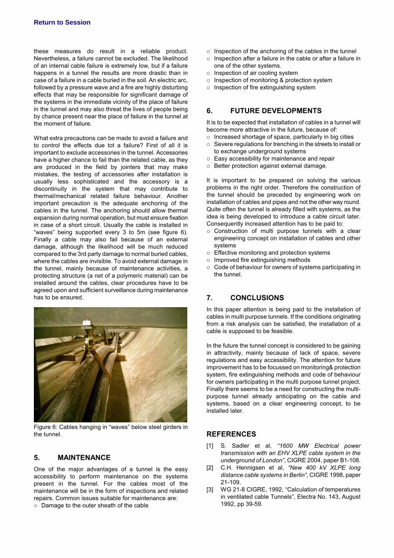
these measures do result in a reliable product. Nevertheless, a failure cannot be excluded. The likelihood of an internal cable failure is extremely low, but if a failure happens in a tunnel the results are more drastic than in case of a failure in a cable buried in the soil. An electric arc, followed by a pressure wave and a fire are highly disturbing effects that may be responsible for significant damage of the systems in the immediate vicinity of the place of failure in the tunnel and may also threat the lives of people being by chance present near the place of failure in the tunnel at the moment of failure. What extra precautions can be made to avoid a failure and to control the effects due tot a failure? First of all it is important to exclude accessories in the tunnel. Accessories have a higher chance to fail than the related cable, as they are produced in the field by jointers that may make mistakes, the testing of accessories after installation is usually less sophisticated and the accessory is a discontinuity in the system that may contribute to thermal/mechanical related failure behaviour. Another important precaution is the adequate anchoring of the cables in the tunnel. The anchoring should allow thermal expansion during normal operation, but must ensure fixation in case of a short circuit. Usually the cable is installed in “waves” being supported every 3 to 5m (see figure 6). Finally a cable may also fail because of an external damage, although the likelihood will be much reduced compared to the 3rd party damage to normal buried cables, where the cables are invisible. To avoid external damage in the tunnel, mainly because of maintenance activities, a protecting structure (a net of a polymeric material) can be installed around the cables, clear procedures have to be agreed upon and sufficient surveillance during maintenance has to be ensured.
Figure 6: Cables hanging in “waves” below steel girders in the tunnel.
5. MAINTENANCE One of the major advantages of a tunnel is the easy accessibility to perform maintenance on the systems present in the tunnel. For the cables most of the maintenance will be in the form of inspections and related repairs. Common issues suitable for maintenance are: o Damage to the outer sheath of the cable
o Inspection of the anchoring of the cables in the tunnel o Inspection after a failure in the cable or after a failure in
one of the other systems. o Inspection of air cooling system o Inspection of monitoring & protection system o Inspection of fire extinguishing system
6. FUTURE DEVELOPMENTS It is to be expected that installation of cables in a tunnel will become more attractive in the future, because of: o Increased shortage of space, particularly in big cities o Severe regulations for trenching in the streets to install or
to exchange underground systems o Easy accessibility for maintenance and repair o Better protection against external damage. It is important to be prepared on solving the various problems in the right order. Therefore the construction of the tunnel should be preceded by engineering work on installation of cables and pipes and not the other way round. Quite often the tunnel is already filled with systems, as the idea is being developed to introduce a cable circuit later. Consequently increased attention has to be paid to: o Construction of multi purpose tunnels with a clear
engineering concept on installation of cables and other systems
o Effective monitoring and protection systems o Improved fire extinguishing methods o Code of behaviour for owners of systems participating in
the tunnel.
7. CONCLUSIONS In this paper attention is being paid to the installation of cables in multi purpose tunnels. If the conditions originating from a risk analysis can be satisfied, the installation of a cable is supposed to be feasible. In the future the tunnel concept is considered to be gaining in attractivity, mainly because of lack of space, severe regulations and easy accessibility. The attention for future improvement has to be focussed on monitoring& protection system, fire extinguishing methods and code of behaviour for owners participating in the multi purpose tunnel project. Finally there seems to be a need for constructing the multi-purpose tunnel already anticipating on the cable and systems, based on a clear engineering concept, to be installed later.
REFERENCES [1] S. Sadler et al, “1600 MW Electrical power
transmission with an EHV XLPE cable system in the underground of London”, CIGRE 2004, paper B1-108.
[2] C.H. Hennigsen et al, “New 400 kV XLPE long distance cable systems in Berlin”, CIGRE 1998, paper 21-109.
[3] WG 21-8 CIGRE, 1992, “Calculation of temperatures in ventilated cable Tunnels”, Electra No. 143, August 1992, pp 39-59.

Return to Session
[4] WG 21-8 CIGRE, 1992, “Calculation of temperatures in ventilated cable Tunnels, second part”, Electra No. 144, October 1992, pp 97-105.
[5] E. Dorison et al, “Current rating of cables installed in tunnels”, Jicable 2003, paper C.8.1.6.
[6] C.A. Arkell et al. “Design and construction of the 400 kV cable system for the Severn tunnel”, Proc. IEE, Vol. 124, No 3, March 1977.