Huntron Workstation Tutorial - StanTronic...
67
© Huntron, Inc 2014 Rev. 6 1 Huntron Workstation Tutorial HUNTRON WORKSTATION TUTORIAL .......................................................................................... 1 HUNTRON WORKSTATION SOFTWARE TUTORIAL..................................................................... 2 Huntron Workstation software 3 Installation Instructions 3 Huntron Workstation Main Interface 4 The Toolbar 5 Hardware Setup 5 Using a ProTrack 7 Using a Tracker Model 30 9 Manual Modes – Tracker and Scanner 9 Creating a Board Test 10 Test Building Procedures 11 Creating a Board Database 11 Adding a New Sequence 12 Component Package Types 13 Adding a New Component 14 Tree/Pin Tab 15 Adding a New Range 16 Mounting a PCB in an Access Prober 20 Prober Setup (Access DH users skip to Camera Offset for 21 Access DH) 21 – Camera Offset part 1 21 Prober Setup – Camera Offset part 2 22 Camera Offset for Access DH 23 Alignment for Access DH 25 Prober setup – Alignment part 1 25 Prober setup – Alignment part 2 26 Creating a Board Image 27 Prober setup – Component Teach; step 1 (DIP package example) 28 (Access DH Users go to “Component Teach with Access DH”) 28 Prober setup – Component Teach; step 2 (DIP package example) 29 Prober setup – Component Teach; step 3 (DIP package example) 30 Prober setup – Component Teach; step 4 (DIP package example) 31
Transcript of Huntron Workstation Tutorial - StanTronic...
© Huntron, Inc 2014 Rev. 6 1
Huntron Workstation Tutorial
HUNTRON WORKSTATION TUTORIAL .......................................................................................... 1
HUNTRON WORKSTATION SOFTWARE TUTORIAL ..................................................................... 2
Huntron Workstation software 3
Installation Instructions 3
Huntron Workstation Main Interface 4
The Toolbar 5
Hardware Setup 5
Using a ProTrack 7
Using a Tracker Model 30 9
Manual Modes – Tracker and Scanner 9
Creating a Board Test 10
Test Building Procedures 11
Creating a Board Database 11
Adding a New Sequence 12
Component Package Types 13
Adding a New Component 14
Tree/Pin Tab 15
Adding a New Range 16
Mounting a PCB in an Access Prober 20
Prober Setup (Access DH users skip to Camera Offset for 21
Access DH) 21
– Camera Offset part 1 21
Prober Setup – Camera Offset part 2 22
Camera Offset for Access DH 23
Alignment for Access DH 25
Prober setup – Alignment part 1 25
Prober setup – Alignment part 2 26
Creating a Board Image 27
Prober setup – Component Teach; step 1 (DIP package example) 28
(Access DH Users go to “Component Teach with Access DH”) 28
Prober setup – Component Teach; step 2 (DIP package example) 29
Prober setup – Component Teach; step 3 (DIP package example) 30
Prober setup – Component Teach; step 4 (DIP package example) 31
© Huntron, Inc 2014 Rev. 6 2
Prober Setup – Component Teach with Access DH 31
Prober setup – Component Teach Height; step 1 (Access DH users go to “Teach Height
for Access DH”) 35
Prober setup – Component Teach Height; step 2 36
Teach Height for Access DH 37
Manual Modes – Camera and Prober 39
Scanning a Sequence or Component 40
Creating a Scan List 41
Scan Results 44
Viewing Signatures – Troublesheet 45
Viewing Signatures Troublesheet Report 46
Viewing Signatures – Right Click 48
View SigAssist Information 49
Component Scans Information 50
Component Scans – Right Clicking (Auxiliary menus) 51
Component Scans – Right Clicking (Auxiliary menus) 52
Component Scans – Right Clicking (Auxiliary menus) 53
Range Editing – Right Clicking (Auxiliary menus) 53
Sequence/Component/Pin Editing – Right Click menus 54
Pin Editing – Right Clicking (Auxiliary menus) 55
Pin Editing 56
Adding CAD data in the Image Pane 57
ViewPCB Image 58
Test Creation - Panelize 59
Test Creation – Convert step 1 60
Test Creation – Convert step 2 61
Test Creation – Convert step 3 62
Test Creation – Convert Status 63
Huntron Workstation Buttons Feature 64
Technical Support 67
© Huntron, Inc 2014 Rev. 6 3
Huntron Workstation software
It is very helpful if you have a working knowledge of Microsoft Windows prior to using
Huntron Workstation.
You are allowed to create a backup copy of the software disk. Your purchase
agreement allows for copies to be made for backup purposes only- copying for
distribution or resale is strictly prohibited.
Installation Instructions
Install the software BEFORE connecting any hardware. Uninstall any previous versions
prior to loading the current version. For more installation details follow the “Getting
Started” sheet included with your Huntron product.
Uninstall any previous versions of Workstation prior to installing the new version.
Insert the Huntron Workstation CDROM. The CDROM should Autorun and begin the
installation process. If your PC has Autorun disabled then open a browse window to
the CD and select WorkstationSetup.exe. This will begin the installation process.
During the install you will be asked to install additional software for Access Probers.
Select the appropriate response based on your Prober hardware.
If you purchased CAD Tools then install using the supplied CD. Follow instructions
listed in the CAD Tools Tutorial.
If you are using Workstation in conjunction with a digital multimeter, follow the
instructions listed in the Workstation DMM Tutorial.
All of the Workstation tutorials are available on the Huntron web site:
www.huntron.com/sales-support/software.htm
© Huntron, Inc 2014 Rev. 6 4
Huntron Workstation Main Interface
When starting Huntron Workstation for the first time, you will be prompted for an
activation code. Type in the code exactly as it is presented on the installation CD.
Huntron Workstation 4 has built-in conversion utilities that enable conversion of board
tests created in 3.X versions of Huntron Workstation.
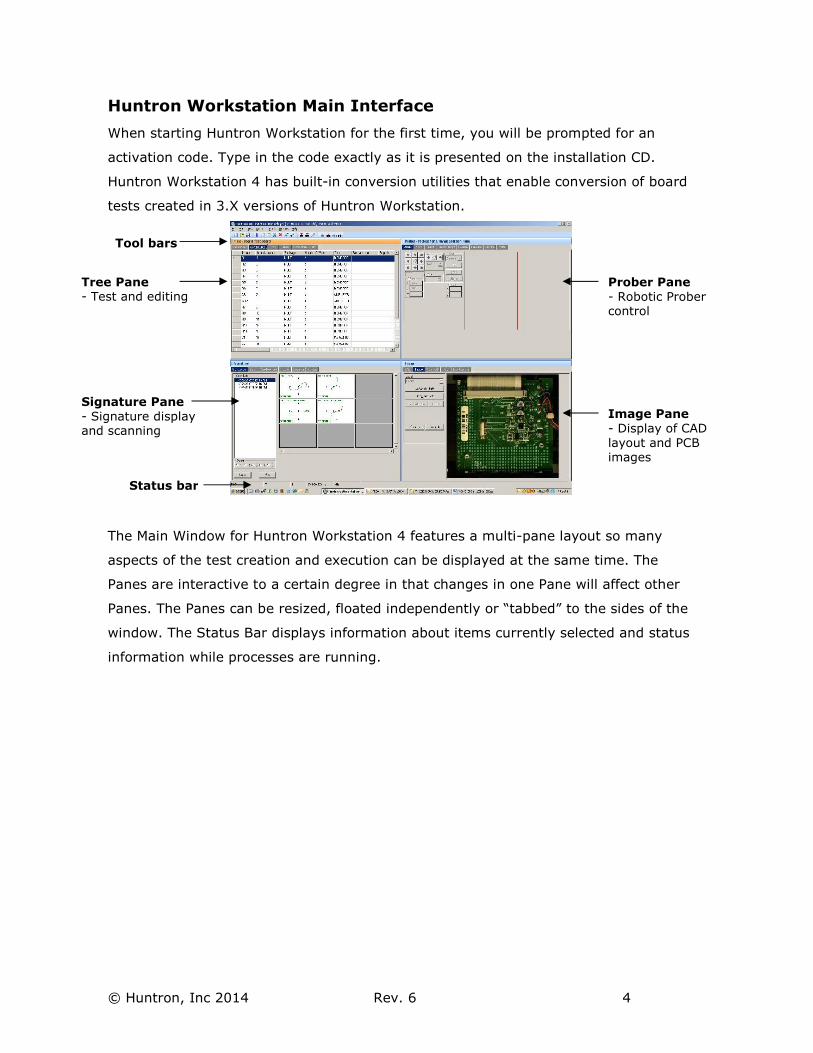
The Main Window for Huntron Workstation 4 features a multi-pane layout so many
aspects of the test creation and execution can be displayed at the same time. The
Panes are interactive to a certain degree in that changes in one Pane will affect other
Panes. The Panes can be resized, floated independently or “tabbed” to the sides of the
window. The Status Bar displays information about items currently selected and status
information while processes are running.
Tree Pane - Test and editing
Signature Pane
- Signature display and scanning
Prober Pane
- Robotic Prober control
Image Pane
- Display of CAD
layout and PCB images
Status bar
Tool bars
© Huntron, Inc 2014 Rev. 6 5
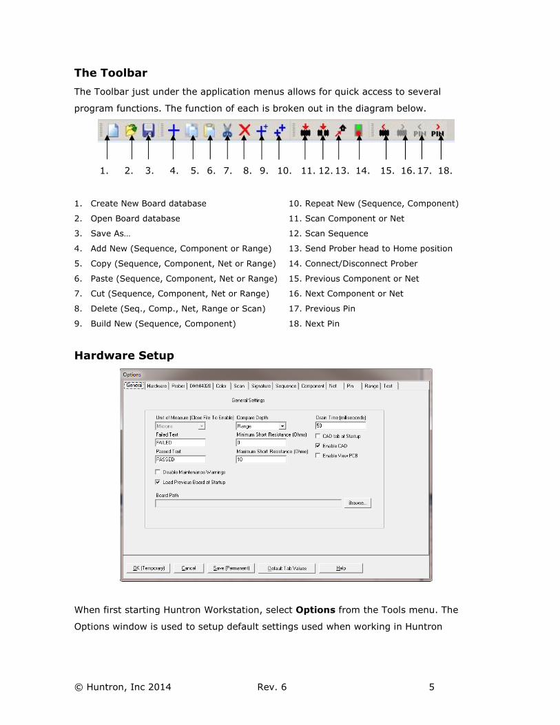
The Toolbar
The Toolbar just under the application menus allows for quick access to several
program functions. The function of each is broken out in the diagram below.
1. 2. 3. 4. 5. 6. 7. 8. 9. 10. 11. 12. 13. 14. 15. 16. 17. 18.
1. Create New Board database 10. Repeat New (Sequence, Component)
2. Open Board database 11. Scan Component or Net
3. Save As… 12. Scan Sequence
4. Add New (Sequence, Component or Range) 13. Send Prober head to Home position
5. Copy (Sequence, Component, Net or Range) 14. Connect/Disconnect Prober
6. Paste (Sequence, Component, Net or Range) 15. Previous Component or Net
7. Cut (Sequence, Component, Net or Range) 16. Next Component or Net
8. Delete (Seq., Comp., Net, Range or Scan) 17. Previous Pin
9. Build New (Sequence, Component) 18. Next Pin
Hardware Setup
When first starting Huntron Workstation, select Options from the Tools menu. The
Options window is used to setup default settings used when working in Huntron
© Huntron, Inc 2014 Rev. 6 6
Workstation. Select the General tab and set the desired Unit of Measure (use Microns
for Huntron Access Probers, Mils for any other Prober).
For this tutorial, the Huntron ProTrack, TrackerPXI and Tracker Model 30 will be
referred to in general as “Trackers”. Specific models will be mentioned by name if
certain software features apply a specific Tracker model. The ProTrack Scanner,
Scanner II and Scanner 31S will be referred to as “Scanners”. Specific models will be
mentioned by name if certain software features apply a specific Scanner model.
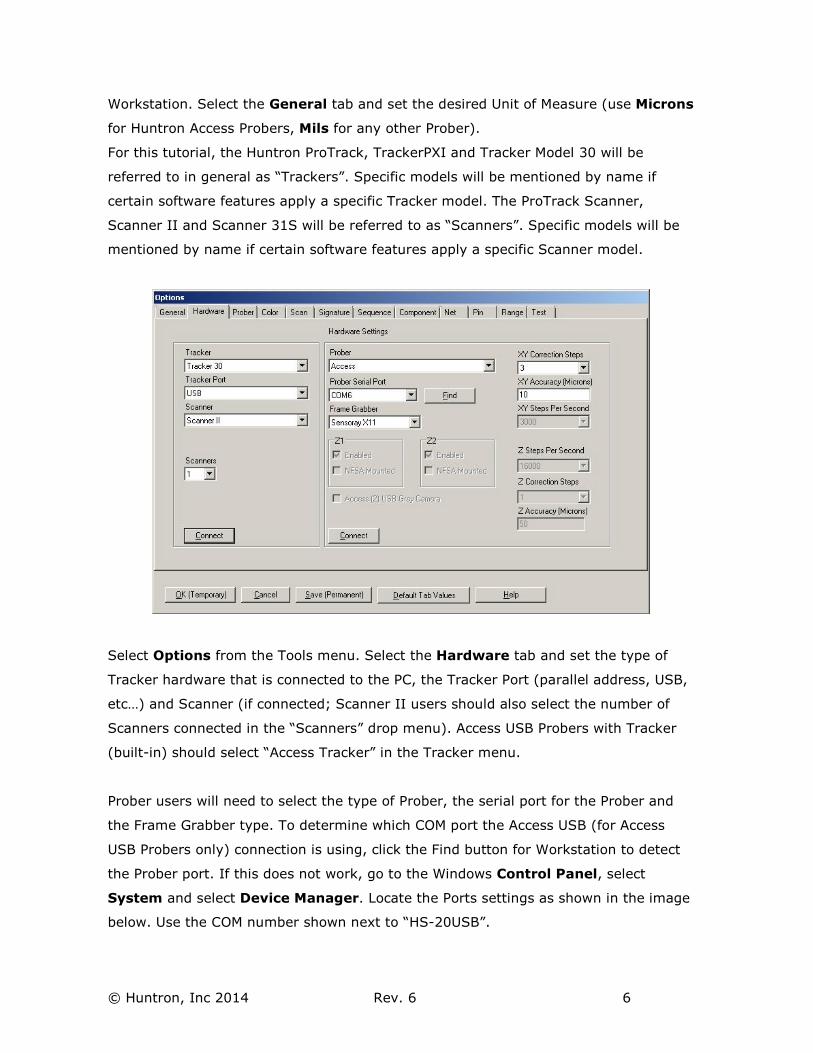
Select Options from the Tools menu. Select the Hardware tab and set the type of
Tracker hardware that is connected to the PC, the Tracker Port (parallel address, USB,
etc…) and Scanner (if connected; Scanner II users should also select the number of
Scanners connected in the “Scanners” drop menu). Access USB Probers with Tracker
(built-in) should select “Access Tracker” in the Tracker menu.
Prober users will need to select the type of Prober, the serial port for the Prober and
the Frame Grabber type. To determine which COM port the Access USB (for Access
USB Probers only) connection is using, click the Find button for Workstation to detect
the Prober port. If this does not work, go to the Windows Control Panel, select
System and select Device Manager. Locate the Ports settings as shown in the image
below. Use the COM number shown next to “HS-20USB”.
© Huntron, Inc 2014 Rev. 6 7
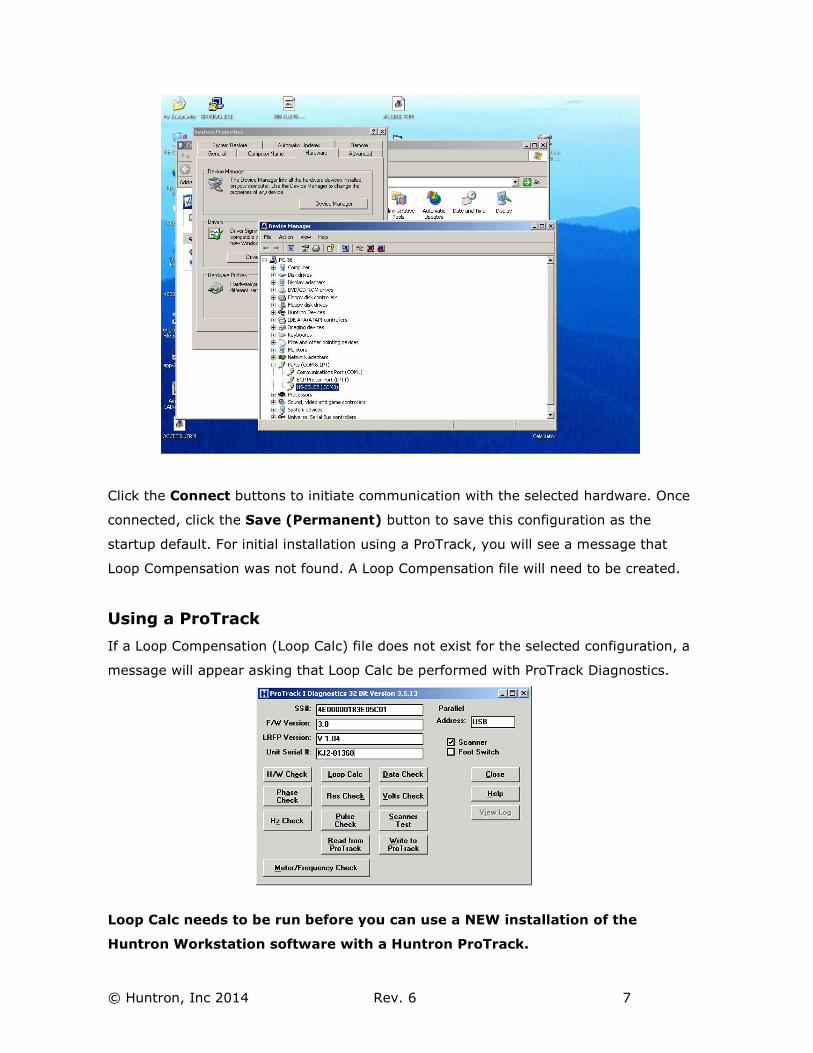
Click the Connect buttons to initiate communication with the selected hardware. Once
connected, click the Save (Permanent) button to save this configuration as the
startup default. For initial installation using a ProTrack, you will see a message that
Loop Compensation was not found. A Loop Compensation file will need to be created.
Using a ProTrack
If a Loop Compensation (Loop Calc) file does not exist for the selected configuration, a
message will appear asking that Loop Calc be performed with ProTrack Diagnostics.
Loop Calc needs to be run before you can use a NEW installation of the
Huntron Workstation software with a Huntron ProTrack.
© Huntron, Inc 2014 Rev. 6 8
- Select Tools/Maintenance/ProTrack Diagnostics from the menu
Run a diagnostic routine by clicking the appropriate button in the ProTrack I
Diagnostics window. Clicking Loop Calc will execute the Hardware Check (except
Scanner Test) before running the Loop Calc routine. The Loop Calc takes
approximately 20 minutes to complete. Once complete, a Loop Compensation file is
created for the selected hardware configuration. You will also be prompted to save a
ProTrack configuration or “.PTC” file (the name will be the serial number you entered
in the Diagnostics window). Click Yes to save the PTC file to your PC. With newer
ProTrack units (serial number prefix KJ3 or KJ4), you will be prompted by another
window displaying “Download the LoopCalc settings into the ProTrack for manual
control?” Click Yes to download the settings. Exit Diagnostics and select
Tools/Options/Hardware and reinitialize the hardware by clicking the
Connect/Disconnect buttons.
Other functions in the ProTrack Diagnostics allow for reading or writing the ProTrack
configuration file. The Read from ProTrack button will retrieve calibration and user
settings from the ProTrack I unit and store them as a text file on the connected
computer in the Program Files/Huntron/Hardware folder. It is recommended this be
performed when setting up the system for the first time or after making changes to
the ProTrack such as the addition of customs ranges and range groups. The file
generated should be stored in a safe location.
The Write to ProTrack button will send the calibration and user information to the
ProTrack I unit. This can be performed if it suspected that the information stored in the
FLASH memory of the ProTrack I has been corrupted.
Using a TrackerPXI
The TrackerPXI comes from the Factory calibrated for standalone use. If the
TrackerPXI is connected to a Prober or other cabling, calibration must be performed.
- Select Tools/Maintenance/TrackerPXI Diagnostics from the menu.
Run Calibrate by clicking the appropriate button in the TrackerPXI Diagnostics window.
When the Calibrate procedure finishes (about 10 minutes), run Verify Calibration. This
also takes about 10 minutes to complete. The Calibration information is stored in the
TrackerPXI and will be used by the software. If changes are made to the cabling or
attached instruments, simply run Calibrate and Verify Calibration again.
© Huntron, Inc 2014 Rev. 6 9
Using a Tracker Model 30
The Tracker Model 30 comes from the Factory calibrated for standalone use. If the
Tracker Model 30 is connected to a Prober, Scanner or other cabling, calibration must
be performed. Access Probers with Tracker inside come from the factory with the
calibration already completed.
- Select Tools/Maintenance/Tracker Model 30 Diagnostics from the menu.
Click the Calibrate button the Tracker Model 30 Diagnostics window. When the
Calibrate procedure finishes (about 10 minutes), run Verify Calibration. This also
takes about 10 minutes to complete. The Calibration information is stored in the
Tracker Model 30 and will be used by the software. If changes are made to the cabling
or attached instruments, simply run Calibrate and Verify Calibration again.
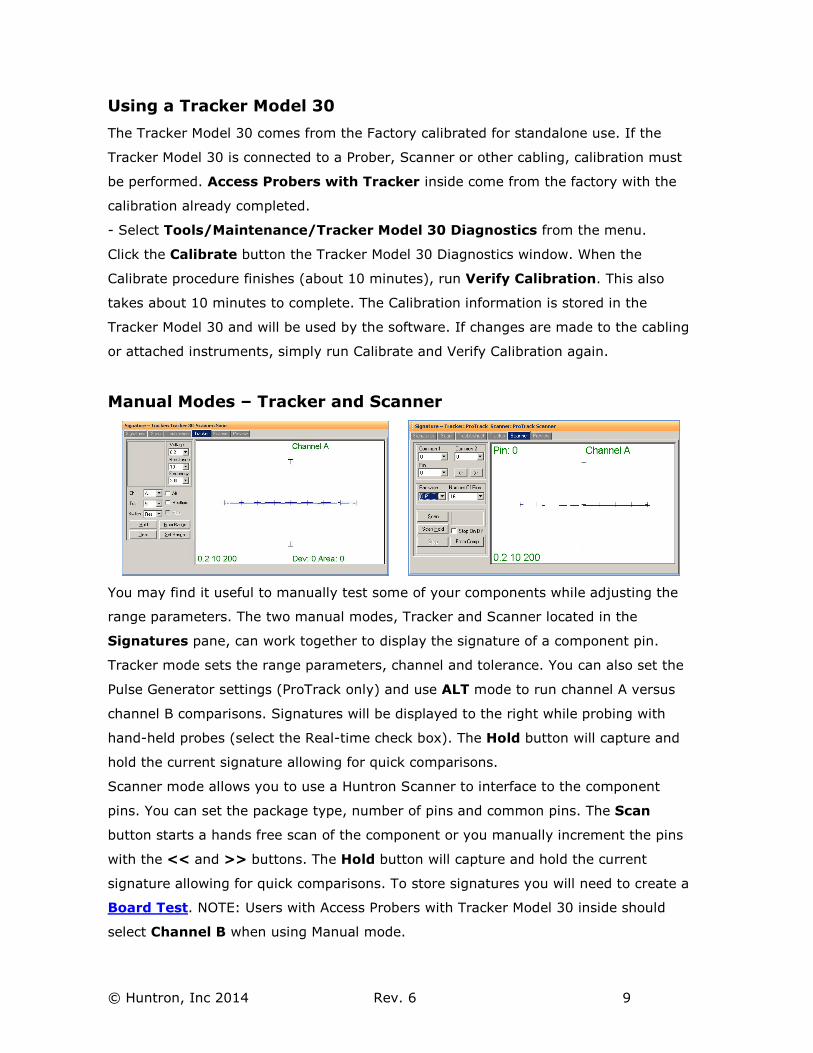
Manual Modes – Tracker and Scanner
You may find it useful to manually test some of your components while adjusting the
range parameters. The two manual modes, Tracker and Scanner located in the
Signatures pane, can work together to display the signature of a component pin.
Tracker mode sets the range parameters, channel and tolerance. You can also set the
Pulse Generator settings (ProTrack only) and use ALT mode to run channel A versus
channel B comparisons. Signatures will be displayed to the right while probing with
hand-held probes (select the Real-time check box). The Hold button will capture and
hold the current signature allowing for quick comparisons.
Scanner mode allows you to use a Huntron Scanner to interface to the component
pins. You can set the package type, number of pins and common pins. The Scan
button starts a hands free scan of the component or you manually increment the pins
with the << and >> buttons. The Hold button will capture and hold the current
signature allowing for quick comparisons. To store signatures you will need to create a
Board Test. NOTE: Users with Access Probers with Tracker Model 30 inside should
select Channel B when using Manual mode.
© Huntron, Inc 2014 Rev. 6 10
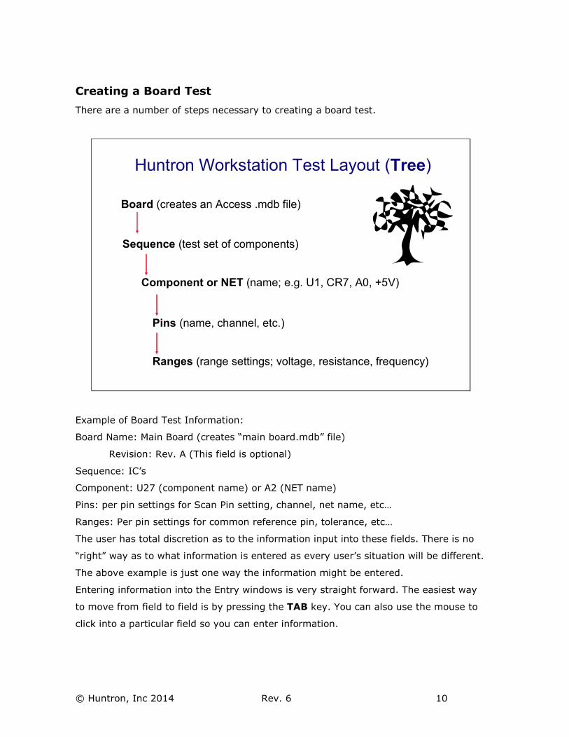
Creating a Board Test
There are a number of steps necessary to creating a board test.
Huntron Workstation Test Layout (Tree)
Board (creates an Access .mdb file)
Sequence (test set of components)
Component or NET (name; e.g. U1, CR7, A0, +5V)
Pins (name, channel, etc.)
Ranges (range settings; voltage, resistance, frequency)
Example of Board Test Information:
Board Name: Main Board (creates “main board.mdb” file)
Revision: Rev. A (This field is optional)
Sequence: IC’s
Component: U27 (component name) or A2 (NET name)
Pins: per pin settings for Scan Pin setting, channel, net name, etc…
Ranges: Per pin settings for common reference pin, tolerance, etc…
The user has total discretion as to the information input into these fields. There is no
“right” way as to what information is entered as every user’s situation will be different.
The above example is just one way the information might be entered.
Entering information into the Entry windows is very straight forward. The easiest way
to move from field to field is by pressing the TAB key. You can also use the mouse to
click into a particular field so you can enter information.
© Huntron, Inc 2014 Rev. 6 11
Test Building Procedures
- Create Test Database in the Tree Pane
o Add Board, Sequence, and Components before teaching or scanning
- Scan Components and Set References (Tracker only or Tracker/Scanner users)
- Perform Camera Offset (Trackers/Probers users)
- Select Alignment points (Tracker/Prober users)
- Teach component pin locations (Tracker/Prober users – teaching all points
before scanning will save you time)
- Scan Sequences and Set References
Listed above is a general outline on how you would proceed when preparing to test a
board. These guidelines apply to all package types and boards. As with any type of
complex test equipment, practice makes perfect so take the time to learn and practice
these procedures.
For tests created using version 3.X, Huntron Workstation has a built-in conversion
utility. See the section on Convert later in this tutorial for more information.
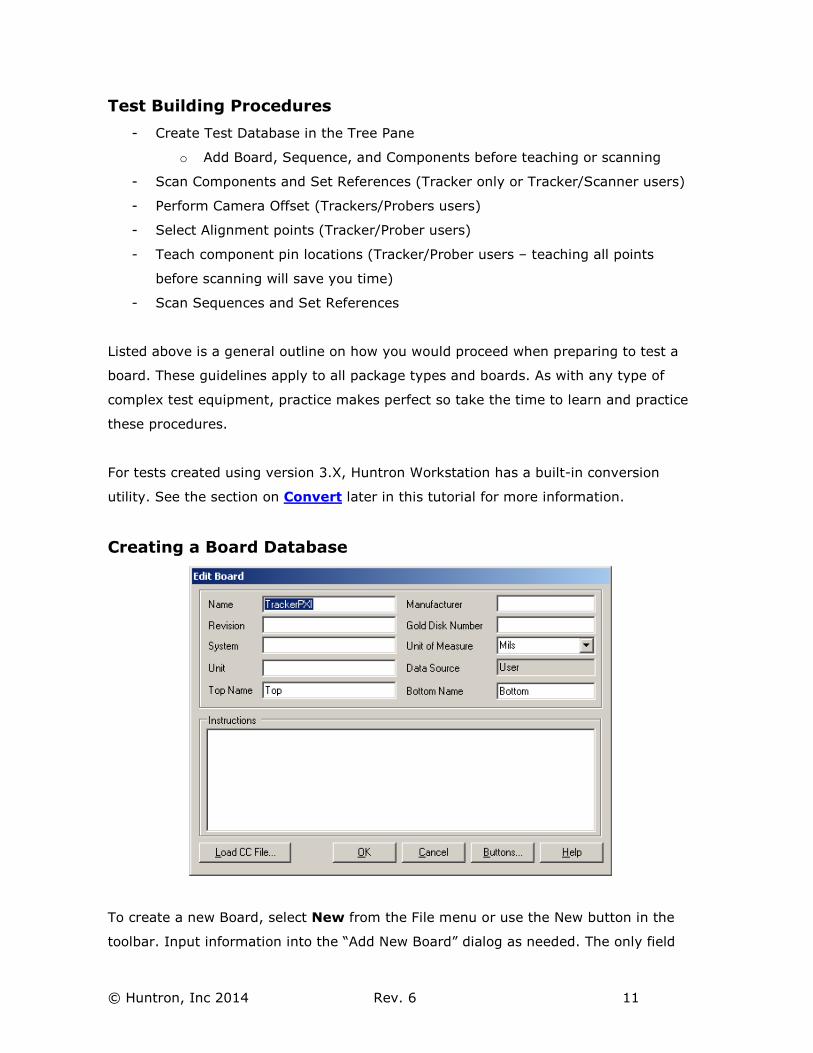
Creating a Board Database
To create a new Board, select New from the File menu or use the New button in the
toolbar. Input information into the “Add New Board” dialog as needed. The only field
© Huntron, Inc 2014 Rev. 6 12
that is required is board Name. Other fields such as Revision, System, Unit,
Manufacturer and Gold Disk Number can be completed with related information if
desired.
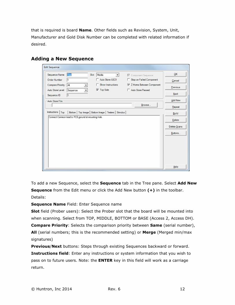
Adding a New Sequence
To add a new Sequence, select the Sequence tab in the Tree pane. Select Add New
Sequence from the Edit menu or click the Add New button (+) in the toolbar.
Details:
Sequence Name Field: Enter Sequence name
Slot field (Prober users): Select the Prober slot that the board will be mounted into
when scanning. Select from TOP, MIDDLE, BOTTOM or BASE (Access 2, Access DH).
Compare Priority: Selects the comparison priority between Same (serial number),
All (serial numbers; this is the recommended setting) or Merge (Merged min/max
signatures)
Previous/Next buttons: Steps through existing Sequences backward or forward.
Instructions field: Enter any instructions or system information that you wish to
pass on to future users. Note: the ENTER key in this field will work as a carriage
return.
© Huntron, Inc 2014 Rev. 6 13
The Add New, Repeat and Build buttons will allow for another new Sequence to be
created saving the current one.
The Delete button will erase the selected Sequence.
NOTE: Access DH users should select the Testers tab and enable “Access DH”.
Other functions within this window can be read about by clicking the HELP button.
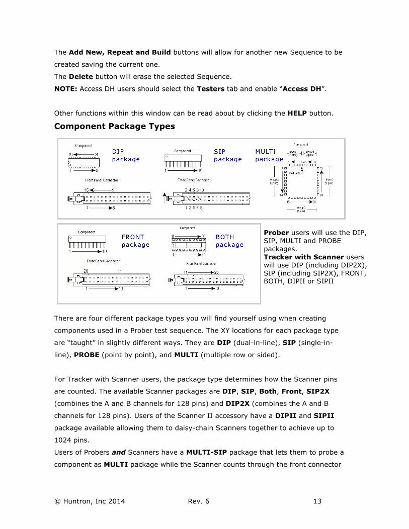
Component Package Types
There are four different package types you will find yourself using when creating
components used in a Prober test sequence. The XY locations for each package type
are “taught” in slightly different ways. They are DIP (dual-in-line), SIP (single-in-
line), PROBE (point by point), and MULTI (multiple row or sided).
For Tracker with Scanner users, the package type determines how the Scanner pins
are counted. The available Scanner packages are DIP, SIP, Both, Front, SIP2X
(combines the A and B channels for 128 pins) and DIP2X (combines the A and B
channels for 128 pins). Users of the Scanner II accessory have a DIPII and SIPII
package available allowing them to daisy-chain Scanners together to achieve up to
1024 pins.
Users of Probers and Scanners have a MULTI-SIP package that lets them to probe a
component as MULTI package while the Scanner counts through the front connector
Prober users will use the DIP,
SIP, MULTI and PROBE
packages.
Tracker with Scanner users
will use DIP (including DIP2X),
SIP (including SIP2X), FRONT, BOTH, DIPII or SIPII
© Huntron, Inc 2014 Rev. 6 14
as a SIP package. This allows for selection of Common references through the
Scanner to the Prober mounted board-under-test using a custom cable.
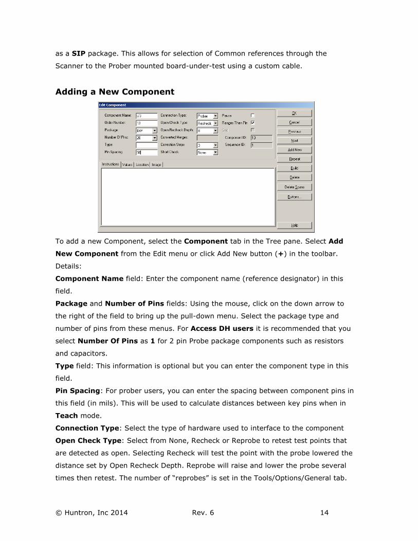
Adding a New Component
To add a new Component, select the Component tab in the Tree pane. Select Add
New Component from the Edit menu or click Add New button (+) in the toolbar.
Details:
Component Name field: Enter the component name (reference designator) in this
field.
Package and Number of Pins fields: Using the mouse, click on the down arrow to
the right of the field to bring up the pull-down menu. Select the package type and
number of pins from these menus. For Access DH users it is recommended that you
select Number Of Pins as 1 for 2 pin Probe package components such as resistors
and capacitors.
Type field: This information is optional but you can enter the component type in this
field.
Pin Spacing: For prober users, you can enter the spacing between component pins in
this field (in mils). This will be used to calculate distances between key pins when in
Teach mode.
Connection Type: Select the type of hardware used to interface to the component
Open Check Type: Select from None, Recheck or Reprobe to retest test points that
are detected as open. Selecting Recheck will test the point with the probe lowered the
distance set by Open Recheck Depth. Reprobe will raise and lower the probe several
times then retest. The number of “reprobes” is set in the Tools/Options/General tab.
© Huntron, Inc 2014 Rev. 6 15
Correction Steps: Sets the maximum amount of correction steps used with the
Huntron Access Prober when moving to the first pin of the component.
Instructions field: Enter any instructions or component information that you wish to
pass on to future users.
Other functions within this window can be read about by clicking the HELP button.
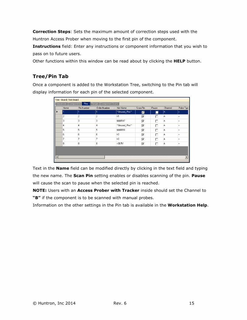
Tree/Pin Tab
Once a component is added to the Workstation Tree, switching to the Pin tab will
display information for each pin of the selected component.
Text in the Name field can be modified directly by clicking in the text field and typing
the new name. The Scan Pin setting enables or disables scanning of the pin. Pause
will cause the scan to pause when the selected pin is reached.
NOTE: Users with an Access Prober with Tracker inside should set the Channel to
“B” if the component is to be scanned with manual probes.
Information on the other settings in the Pin tab is available in the Workstation Help.
© Huntron, Inc 2014 Rev. 6 16
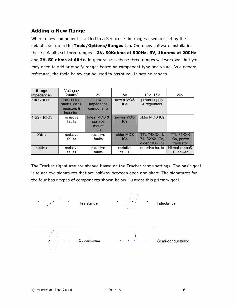
Adding a New Range
When a new component is added to a Sequence the ranges used are set by the
defaults set up in the Tools/Options/Ranges tab. On a new software installation
these defaults set three ranges – 3V, 50Kohms at 500Hz; 3V, 1Kohms at 200Hz
and 3V, 50 ohms at 60Hz. In general use, these three ranges will work well but you
may need to add or modify ranges based on component type and value. As a general
reference, the table below can be used to assist you in setting ranges.
The Tracker signatures are shaped based on the Tracker range settings. The basic goal
is to achieve signatures that are halfway between open and short. The signatures for
the four basic types of components shown below illustrate this primary goal.
Range
Impedance↓
Voltage> 200mV
3V
6V
10V -15V
20V
10Ω - 100Ω continuity, shorts, caps, resistors & inductors
low impedance
components
newer MOS ICs
power supply & regulators
1KΩ - 10KΩ resistive faults
latest MOS & surface mount
ICs
newer MOS ICs
older MOS ICs
20KΩ resistive faults
resistive faults
older MOS ICs
TTL 74XXX & 74LSXXX ICs, older MOS Ics
TTL 74XXX ICs, power transistor
100KΩ resistive faults
resistive faults
resistive faults
resistive faults Hi resistance& Hi power
Resistance
Capacitance
Inductance
Semi-conductance
© Huntron, Inc 2014 Rev. 6 17
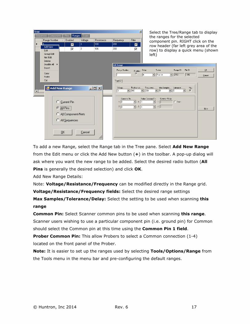
To add a new Range, select the Range tab in the Tree pane. Select Add New Range
from the Edit menu or click the Add New button (+) in the toolbar. A pop-up dialog will
ask where you want the new range to be added. Select the desired radio button (All
Pins is generally the desired selection) and click OK.
Add New Range Details:
Note: Voltage/Resistance/Frequency can be modified directly in the Range grid.
Voltage/Resistance/Frequency fields: Select the desired range settings
Max Samples/Tolerance/Delay: Select the setting to be used when scanning this
range
Common Pin: Select Scanner common pins to be used when scanning this range.
Scanner users wishing to use a particular component pin (i.e. ground pin) for Common
should select the Common pin at this time using the Common Pin 1 field.
Prober Common Pin: This allow Probers to select a Common connection (1-4)
located on the front panel of the Prober.
Note: It is easier to set up the ranges used by selecting Tools/Options/Range from
the Tools menu in the menu bar and pre-configuring the default ranges.
Select the Tree/Range tab to display
the ranges for the selected
component pin. RIGHT click on the
row header (far left grey area of the
row) to display a quick menu (shown left)
© Huntron, Inc 2014 Rev. 6 18
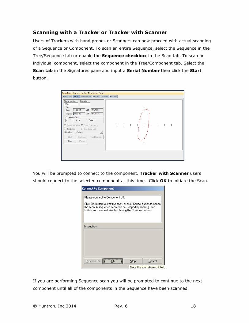
Scanning with a Tracker or Tracker with Scanner
Users of Trackers with hand probes or Scanners can now proceed with actual scanning
of a Sequence or Component. To scan an entire Sequence, select the Sequence in the
Tree/Sequence tab or enable the Sequence checkbox in the Scan tab. To scan an
individual component, select the component in the Tree/Component tab. Select the
Scan tab in the Signatures pane and input a Serial Number then click the Start
button.
You will be prompted to connect to the component. Tracker with Scanner users
should connect to the selected component at this time. Click OK to initiate the Scan.
If you are performing Sequence scan you will be prompted to continue to the next
component until all of the components in the Sequence have been scanned.
© Huntron, Inc 2014 Rev. 6 19
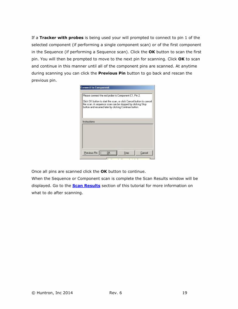
If a Tracker with probes is being used your will prompted to connect to pin 1 of the
selected component (if performing a single component scan) or of the first component
in the Sequence (if performing a Sequence scan). Click the OK button to scan the first
pin. You will then be prompted to move to the next pin for scanning. Click OK to scan
and continue in this manner until all of the component pins are scanned. At anytime
during scanning you can click the Previous Pin button to go back and rescan the
previous pin.
Once all pins are scanned click the OK button to continue.
When the Sequence or Component scan is complete the Scan Results window will be
displayed. Go to the Scan Results section of this tutorial for more information on
what to do after scanning.
© Huntron, Inc 2014 Rev. 6 20
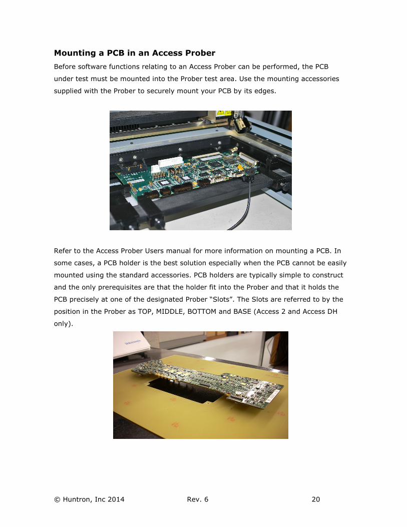
Mounting a PCB in an Access Prober
Before software functions relating to an Access Prober can be performed, the PCB
under test must be mounted into the Prober test area. Use the mounting accessories
supplied with the Prober to securely mount your PCB by its edges.
Refer to the Access Prober Users manual for more information on mounting a PCB. In
some cases, a PCB holder is the best solution especially when the PCB cannot be easily
mounted using the standard accessories. PCB holders are typically simple to construct
and the only prerequisites are that the holder fit into the Prober and that it holds the
PCB precisely at one of the designated Prober “Slots”. The Slots are referred to by the
position in the Prober as TOP, MIDDLE, BOTTOM and BASE (Access 2 and Access DH
only).
© Huntron, Inc 2014 Rev. 6 21
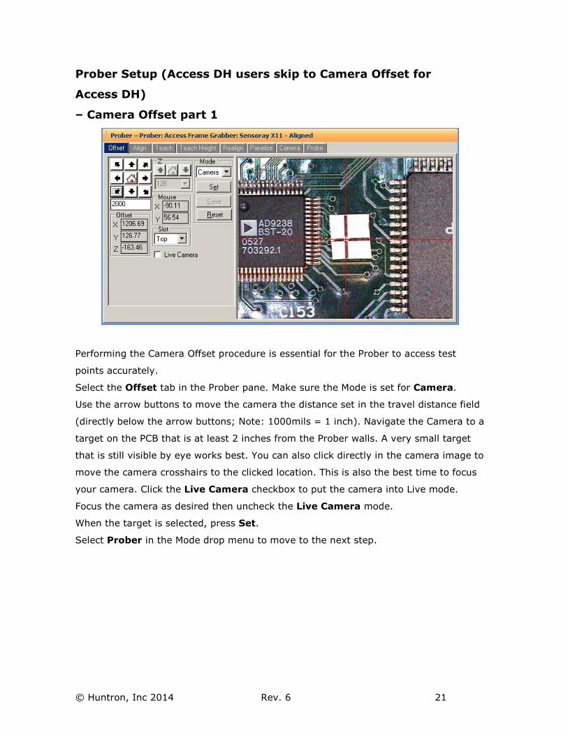
Prober Setup (Access DH users skip to Camera Offset for
Access DH)
– Camera Offset part 1
Performing the Camera Offset procedure is essential for the Prober to access test
points accurately.
Select the Offset tab in the Prober pane. Make sure the Mode is set for Camera.
Use the arrow buttons to move the camera the distance set in the travel distance field
(directly below the arrow buttons; Note: 1000mils = 1 inch). Navigate the Camera to a
target on the PCB that is at least 2 inches from the Prober walls. A very small target
that is still visible by eye works best. You can also click directly in the camera image to
move the camera crosshairs to the clicked location. This is also the best time to focus
your camera. Click the Live Camera checkbox to put the camera into Live mode.
Focus the camera as desired then uncheck the Live Camera mode.
When the target is selected, press Set.
Select Prober in the Mode drop menu to move to the next step.
© Huntron, Inc 2014 Rev. 6 22
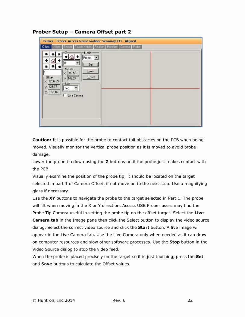
Prober Setup – Camera Offset part 2
Caution: It is possible for the probe to contact tall obstacles on the PCB when being
moved. Visually monitor the vertical probe position as it is moved to avoid probe
damage.
Lower the probe tip down using the Z buttons until the probe just makes contact with
the PCB.
Visually examine the position of the probe tip; it should be located on the target
selected in part 1 of Camera Offset, if not move on to the next step. Use a magnifying
glass if necessary.
Use the XY buttons to navigate the probe to the target selected in Part 1. The probe
will lift when moving in the X or Y direction. Access USB Prober users may find the
Probe Tip Camera useful in setting the probe tip on the offset target. Select the Live
Camera tab in the Image pane then click the Select button to display the video source
dialog. Select the correct video source and click the Start button. A live image will
appear in the Live Camera tab. Use the Live Camera only when needed as it can draw
on computer resources and slow other software processes. Use the Stop button in the
Video Source dialog to stop the video feed.
When the probe is placed precisely on the target so it is just touching, press the Set
and Save buttons to calculate the Offset values.
© Huntron, Inc 2014 Rev. 6 23
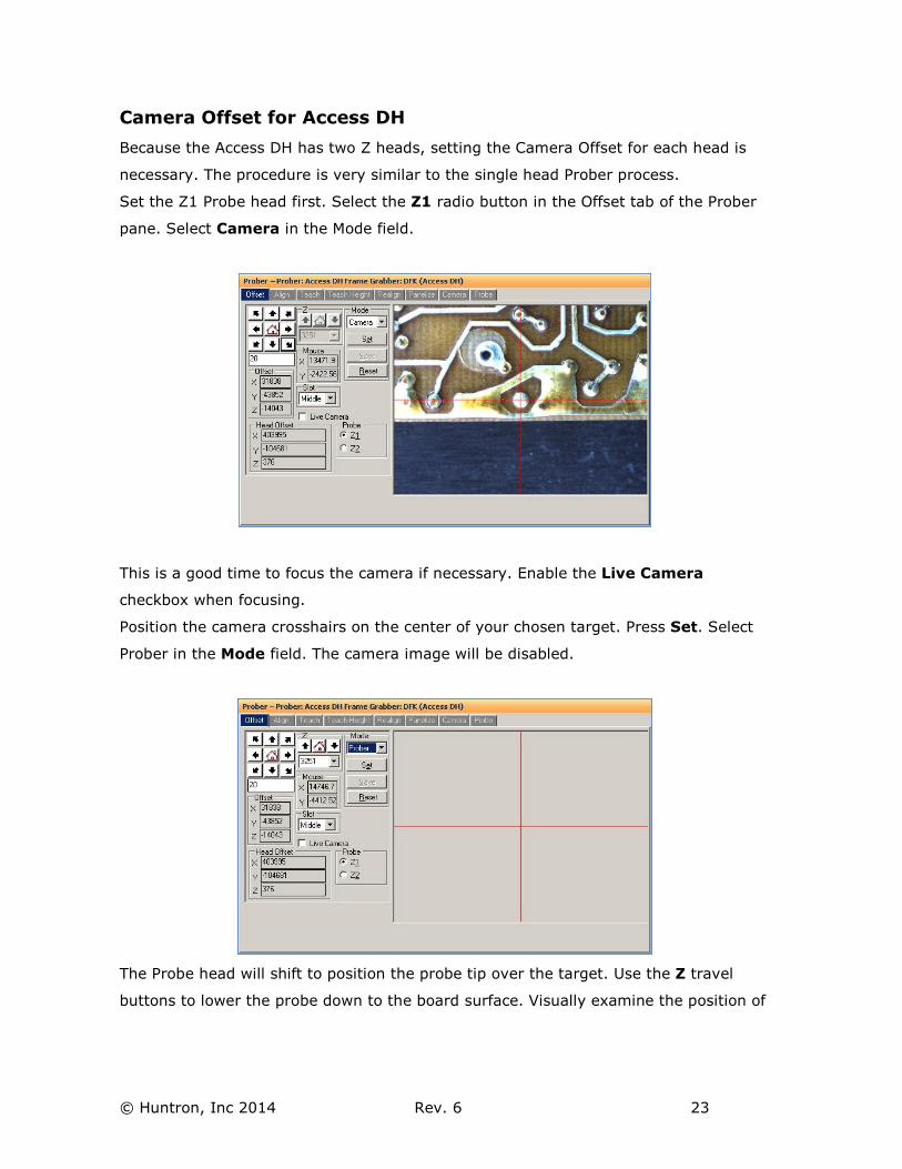
Camera Offset for Access DH
Because the Access DH has two Z heads, setting the Camera Offset for each head is
necessary. The procedure is very similar to the single head Prober process.
Set the Z1 Probe head first. Select the Z1 radio button in the Offset tab of the Prober
pane. Select Camera in the Mode field.
This is a good time to focus the camera if necessary. Enable the Live Camera
checkbox when focusing.
Position the camera crosshairs on the center of your chosen target. Press Set. Select
Prober in the Mode field. The camera image will be disabled.
The Probe head will shift to position the probe tip over the target. Use the Z travel
buttons to lower the probe down to the board surface. Visually examine the position of
© Huntron, Inc 2014 Rev. 6 24
the probe tip; it should be located on the target selected earlier with the Camera, if
not move on to the next step. Use a magnifying glass if necessary.
Use the XY buttons to navigate the probe to the target selected earlier. The probe will
lift when moving in the X or Y direction. When the probe is placed precisely on the
target so it is just touching, press the Set.
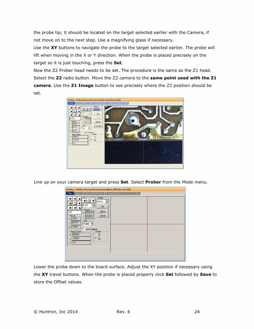
Now the Z2 Prober head needs to be set. The procedure is the same as the Z1 head.
Select the Z2 radio button. Move the Z2 camera to the same point used with the Z1
camera. Use the Z1 Image button to see precisely where the Z2 position should be
set.
Line up on your camera target and press Set. Select Prober from the Mode menu.
Lower the probe down to the board surface. Adjust the XY position if necessary using
the XY travel buttons. When the probe is placed properly click Set followed by Save to
store the Offset values.
© Huntron, Inc 2014 Rev. 6 25
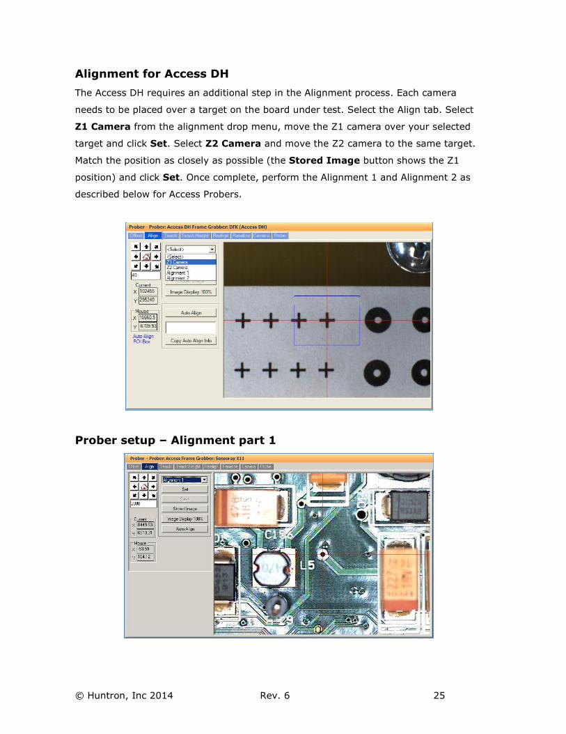
Alignment for Access DH
The Access DH requires an additional step in the Alignment process. Each camera
needs to be placed over a target on the board under test. Select the Align tab. Select
Z1 Camera from the alignment drop menu, move the Z1 camera over your selected
target and click Set. Select Z2 Camera and move the Z2 camera to the same target.
Match the position as closely as possible (the Stored Image button shows the Z1
position) and click Set. Once complete, perform the Alignment 1 and Alignment 2 as
described below for Access Probers.
Prober setup – Alignment part 1
© Huntron, Inc 2014 Rev. 6 26
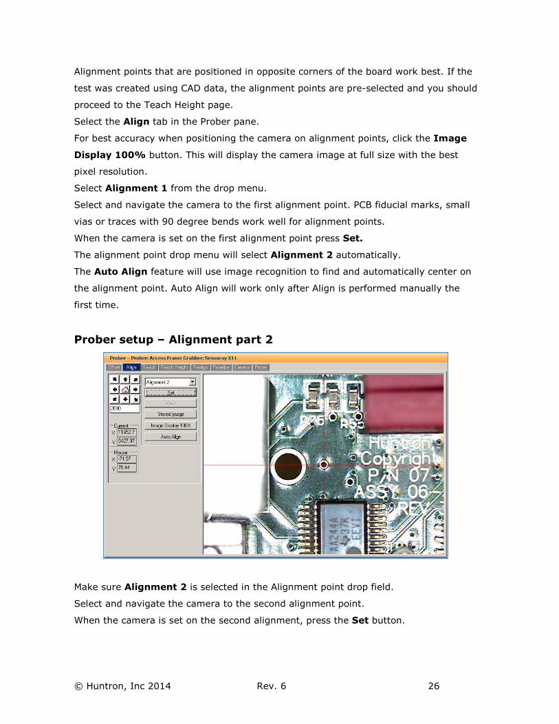
Alignment points that are positioned in opposite corners of the board work best. If the
test was created using CAD data, the alignment points are pre-selected and you should
proceed to the Teach Height page.
Select the Align tab in the Prober pane.
For best accuracy when positioning the camera on alignment points, click the Image
Display 100% button. This will display the camera image at full size with the best
pixel resolution.
Select Alignment 1 from the drop menu.
Select and navigate the camera to the first alignment point. PCB fiducial marks, small
vias or traces with 90 degree bends work well for alignment points.
When the camera is set on the first alignment point press Set.
The alignment point drop menu will select Alignment 2 automatically.
The Auto Align feature will use image recognition to find and automatically center on
the alignment point. Auto Align will work only after Align is performed manually the
first time.
Prober setup – Alignment part 2
Make sure Alignment 2 is selected in the Alignment point drop field.
Select and navigate the camera to the second alignment point.
When the camera is set on the second alignment, press the Set button.
© Huntron, Inc 2014 Rev. 6 27
The Auto Align feature will use image recognition to find and automatically center on
the alignment point. Auto Align will only work after Align is performed manually the
first time.
Press the Save button to store the alignment points and the alignment point images.
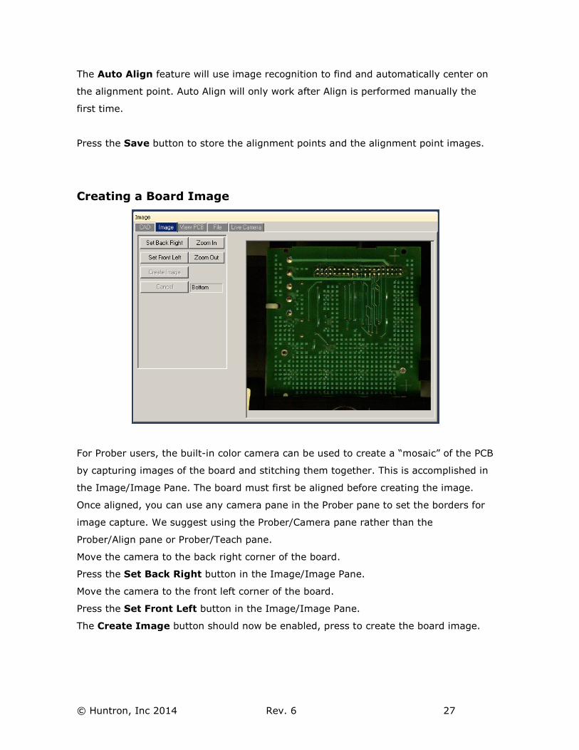
Creating a Board Image
For Prober users, the built-in color camera can be used to create a “mosaic” of the PCB
by capturing images of the board and stitching them together. This is accomplished in
the Image/Image Pane. The board must first be aligned before creating the image.
Once aligned, you can use any camera pane in the Prober pane to set the borders for
image capture. We suggest using the Prober/Camera pane rather than the
Prober/Align pane or Prober/Teach pane.
Move the camera to the back right corner of the board.
Press the Set Back Right button in the Image/Image Pane.
Move the camera to the front left corner of the board.
Press the Set Front Left button in the Image/Image Pane.
The Create Image button should now be enabled, press to create the board image.
© Huntron, Inc 2014 Rev. 6 28
Larger boards will require more time to create the board image. Once the board image
is created, you can click a point on the board image and the Prober will move the
camera to that point. This is especially useful in Teach mode to aide in navigating the
camera to component positions.
Right-click on the image to display a menu to Delete, Copy or Save As the board
image.
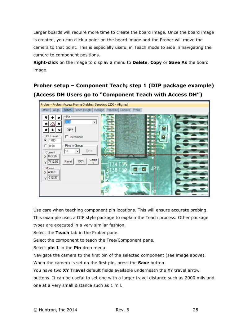
Prober setup – Component Teach; step 1 (DIP package example)
(Access DH Users go to “Component Teach with Access DH”)
Use care when teaching component pin locations. This will ensure accurate probing.
This example uses a DIP style package to explain the Teach process. Other package
types are executed in a very similar fashion.
Select the Teach tab in the Prober pane.
Select the component to teach the Tree/Component pane.
Select pin 1 in the Pin drop menu.
Navigate the camera to the first pin of the selected component (see image above).
When the camera is set on the first pin, press the Save button.
You have two XY Travel default fields available underneath the XY travel arrow
buttons. It can be useful to set one with a larger travel distance such as 2000 mils and
one at a very small distance such as 1 mil.
© Huntron, Inc 2014 Rev. 6 29
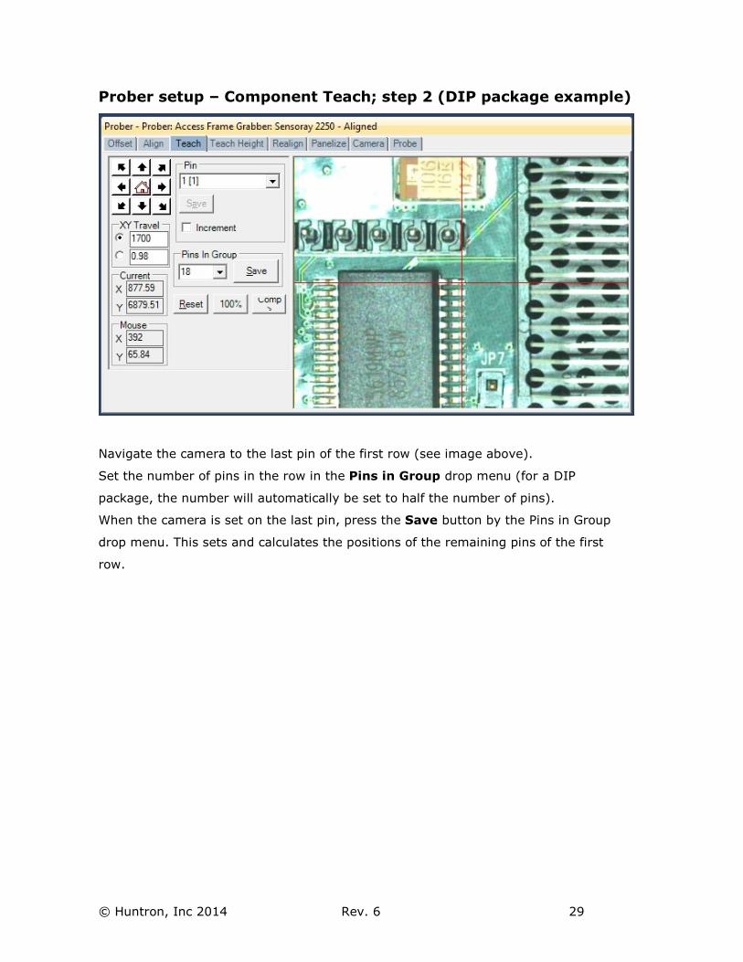
Prober setup – Component Teach; step 2 (DIP package example)
Navigate the camera to the last pin of the first row (see image above).
Set the number of pins in the row in the Pins in Group drop menu (for a DIP
package, the number will automatically be set to half the number of pins).
When the camera is set on the last pin, press the Save button by the Pins in Group
drop menu. This sets and calculates the positions of the remaining pins of the first
row.
© Huntron, Inc 2014 Rev. 6 30
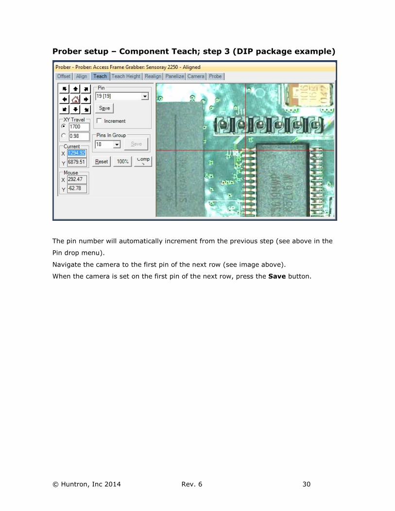
Prober setup – Component Teach; step 3 (DIP package example)
The pin number will automatically increment from the previous step (see above in the
Pin drop menu).
Navigate the camera to the first pin of the next row (see image above).
When the camera is set on the first pin of the next row, press the Save button.
© Huntron, Inc 2014 Rev. 6 31
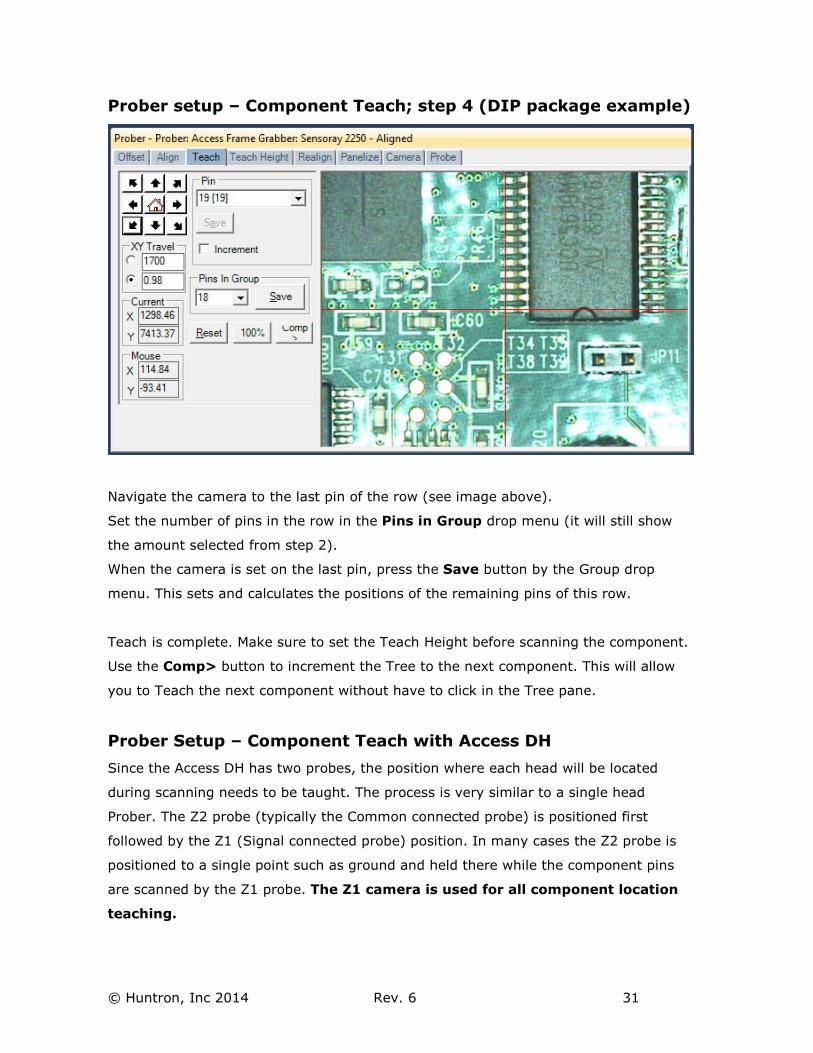
Prober setup – Component Teach; step 4 (DIP package example)
Navigate the camera to the last pin of the row (see image above).
Set the number of pins in the row in the Pins in Group drop menu (it will still show
the amount selected from step 2).
When the camera is set on the last pin, press the Save button by the Group drop
menu. This sets and calculates the positions of the remaining pins of this row.
Teach is complete. Make sure to set the Teach Height before scanning the component.
Use the Comp> button to increment the Tree to the next component. This will allow
you to Teach the next component without have to click in the Tree pane.
Prober Setup – Component Teach with Access DH
Since the Access DH has two probes, the position where each head will be located
during scanning needs to be taught. The process is very similar to a single head
Prober. The Z2 probe (typically the Common connected probe) is positioned first
followed by the Z1 (Signal connected probe) position. In many cases the Z2 probe is
positioned to a single point such as ground and held there while the component pins
are scanned by the Z1 probe. The Z1 camera is used for all component location
teaching.
© Huntron, Inc 2014 Rev. 6 32
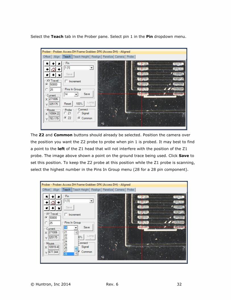
Select the Teach tab in the Prober pane. Select pin 1 in the Pin dropdown menu.
The Z2 and Common buttons should already be selected. Position the camera over
the position you want the Z2 probe to probe when pin 1 is probed. It may best to find
a point to the left of the Z1 head that will not interfere with the position of the Z1
probe. The image above shown a point on the ground trace being used. Click Save to
set this position. To keep the Z2 probe at this position while the Z1 probe is scanning,
select the highest number in the Pins In Group menu (28 for a 28 pin component).
© Huntron, Inc 2014 Rev. 6 33
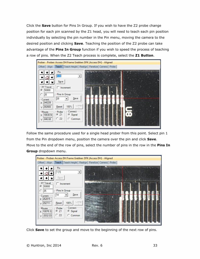
Click the Save button for Pins In Group. If you wish to have the Z2 probe change
position for each pin scanned by the Z1 head, you will need to teach each pin position
individually by selecting the pin number in the Pin menu, moving the camera to the
desired position and clicking Save. Teaching the position of the Z2 probe can take
advantage of the Pins In Group function if you wish to speed the process of teaching
a row of pins. When the Z2 Teach process is complete, select the Z1 Button.
Follow the same procedure used for a single head prober from this point. Select pin 1
from the Pin dropdown menu, position the camera over the pin and click Save.
Move to the end of the row of pins, select the number of pins in the row in the Pins In
Group dropdown menu.
Click Save to set the group and move to the beginning of the next row of pins.
© Huntron, Inc 2014 Rev. 6 34
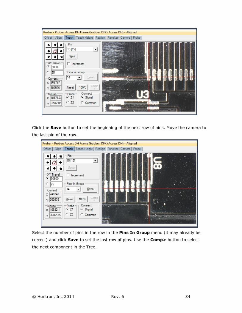
Click the Save button to set the beginning of the next row of pins. Move the camera to
the last pin of the row.
Select the number of pins in the row in the Pins In Group menu (it may already be
correct) and click Save to set the last row of pins. Use the Comp> button to select
the next component in the Tree.
© Huntron, Inc 2014 Rev. 6 35
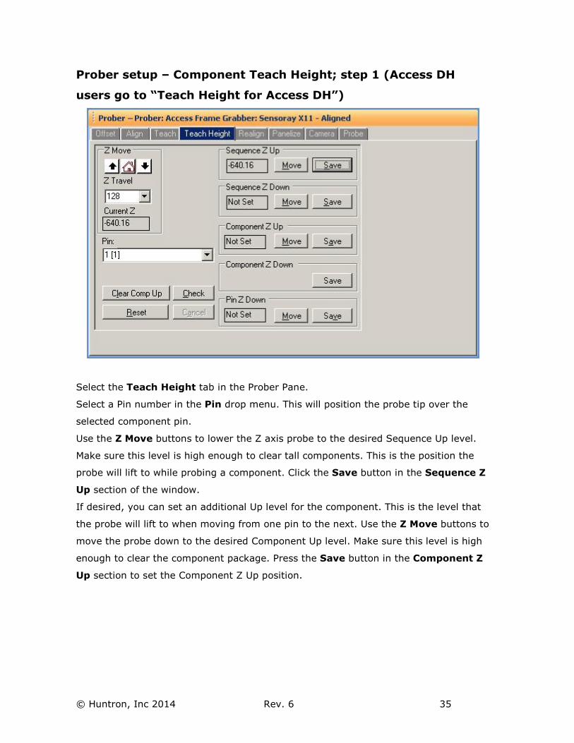
Prober setup – Component Teach Height; step 1 (Access DH
users go to “Teach Height for Access DH”)
Select the Teach Height tab in the Prober Pane.
Select a Pin number in the Pin drop menu. This will position the probe tip over the
selected component pin.
Use the Z Move buttons to lower the Z axis probe to the desired Sequence Up level.
Make sure this level is high enough to clear tall components. This is the position the
probe will lift to while probing a component. Click the Save button in the Sequence Z
Up section of the window.
If desired, you can set an additional Up level for the component. This is the level that
the probe will lift to when moving from one pin to the next. Use the Z Move buttons to
move the probe down to the desired Component Up level. Make sure this level is high
enough to clear the component package. Press the Save button in the Component Z
Up section to set the Component Z Up position.
© Huntron, Inc 2014 Rev. 6 36
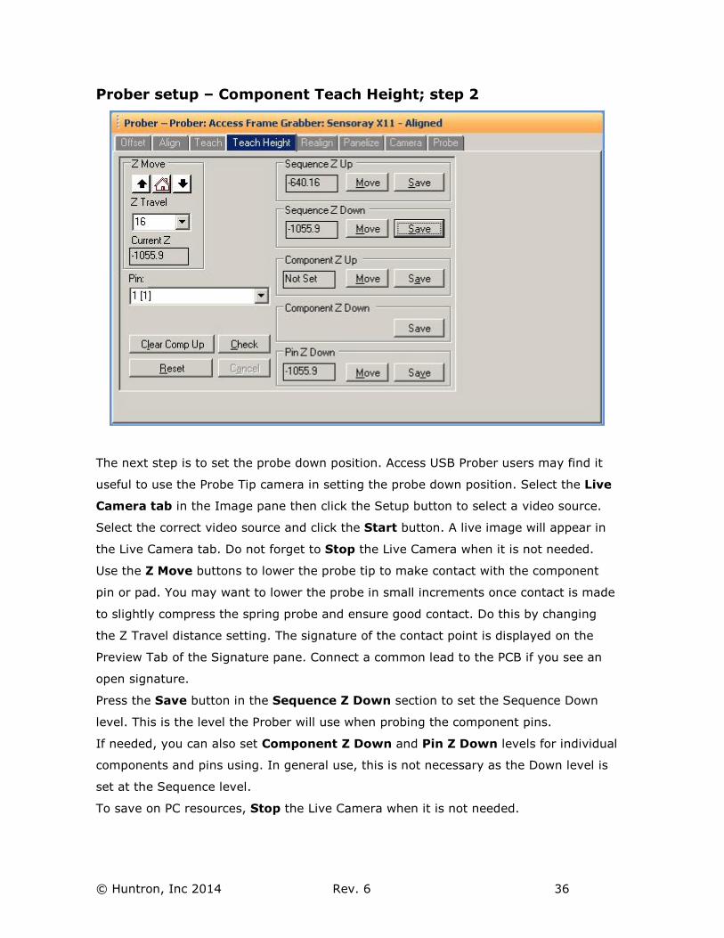
Prober setup – Component Teach Height; step 2
The next step is to set the probe down position. Access USB Prober users may find it
useful to use the Probe Tip camera in setting the probe down position. Select the Live
Camera tab in the Image pane then click the Setup button to select a video source.
Select the correct video source and click the Start button. A live image will appear in
the Live Camera tab. Do not forget to Stop the Live Camera when it is not needed.
Use the Z Move buttons to lower the probe tip to make contact with the component
pin or pad. You may want to lower the probe in small increments once contact is made
to slightly compress the spring probe and ensure good contact. Do this by changing
the Z Travel distance setting. The signature of the contact point is displayed on the
Preview Tab of the Signature pane. Connect a common lead to the PCB if you see an
open signature.
Press the Save button in the Sequence Z Down section to set the Sequence Down
level. This is the level the Prober will use when probing the component pins.
If needed, you can also set Component Z Down and Pin Z Down levels for individual
components and pins using. In general use, this is not necessary as the Down level is
set at the Sequence level.
To save on PC resources, Stop the Live Camera when it is not needed.
© Huntron, Inc 2014 Rev. 6 37
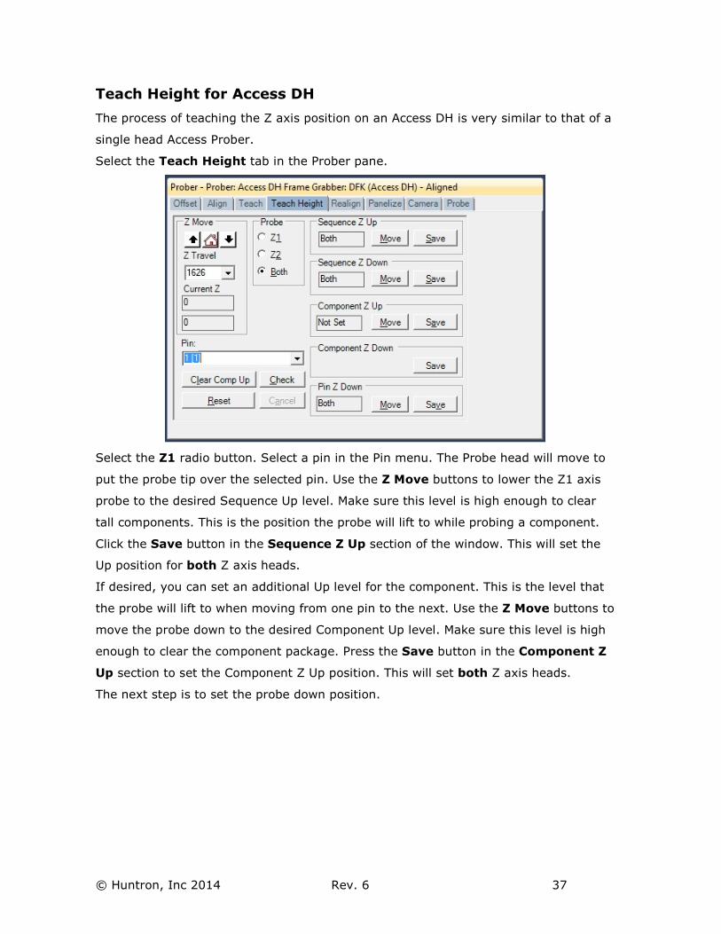
Teach Height for Access DH
The process of teaching the Z axis position on an Access DH is very similar to that of a
single head Access Prober.
Select the Teach Height tab in the Prober pane.
Select the Z1 radio button. Select a pin in the Pin menu. The Probe head will move to
put the probe tip over the selected pin. Use the Z Move buttons to lower the Z1 axis
probe to the desired Sequence Up level. Make sure this level is high enough to clear
tall components. This is the position the probe will lift to while probing a component.
Click the Save button in the Sequence Z Up section of the window. This will set the
Up position for both Z axis heads.
If desired, you can set an additional Up level for the component. This is the level that
the probe will lift to when moving from one pin to the next. Use the Z Move buttons to
move the probe down to the desired Component Up level. Make sure this level is high
enough to clear the component package. Press the Save button in the Component Z
Up section to set the Component Z Up position. This will set both Z axis heads.
The next step is to set the probe down position.
© Huntron, Inc 2014 Rev. 6 38
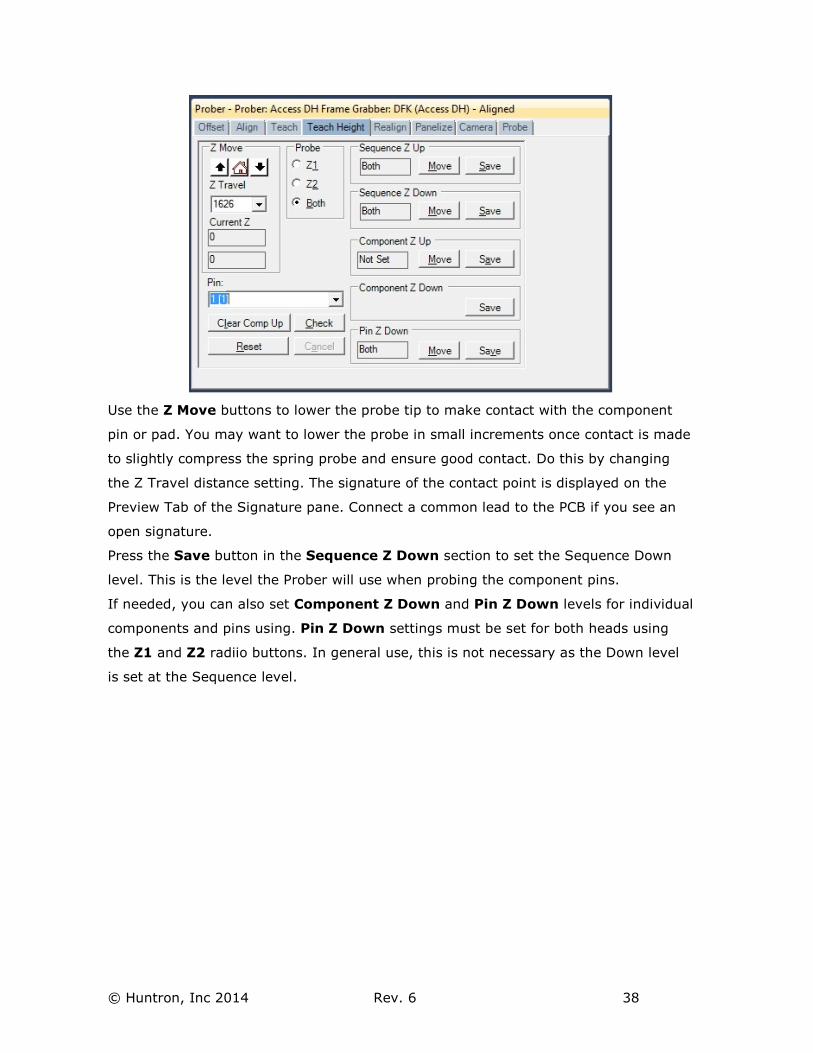
Use the Z Move buttons to lower the probe tip to make contact with the component
pin or pad. You may want to lower the probe in small increments once contact is made
to slightly compress the spring probe and ensure good contact. Do this by changing
the Z Travel distance setting. The signature of the contact point is displayed on the
Preview Tab of the Signature pane. Connect a common lead to the PCB if you see an
open signature.
Press the Save button in the Sequence Z Down section to set the Sequence Down
level. This is the level the Prober will use when probing the component pins.
If needed, you can also set Component Z Down and Pin Z Down levels for individual
components and pins using. Pin Z Down settings must be set for both heads using
the Z1 and Z2 radiio buttons. In general use, this is not necessary as the Down level
is set at the Sequence level.
© Huntron, Inc 2014 Rev. 6 39
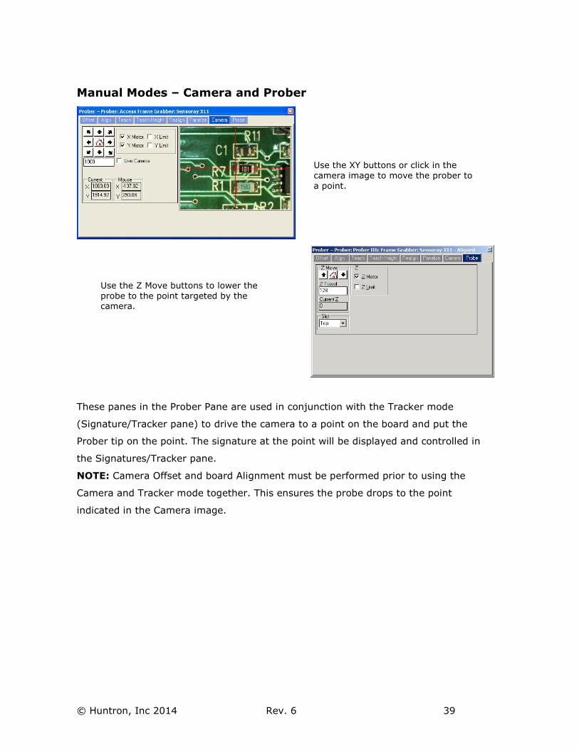
Manual Modes – Camera and Prober
These panes in the Prober Pane are used in conjunction with the Tracker mode
(Signature/Tracker pane) to drive the camera to a point on the board and put the
Prober tip on the point. The signature at the point will be displayed and controlled in
the Signatures/Tracker pane.
NOTE: Camera Offset and board Alignment must be performed prior to using the
Camera and Tracker mode together. This ensures the probe drops to the point
indicated in the Camera image.
Use the XY buttons or click in the
camera image to move the prober to
a point.
Use the Z Move buttons to lower the
probe to the point targeted by the camera.
© Huntron, Inc 2014 Rev. 6 40
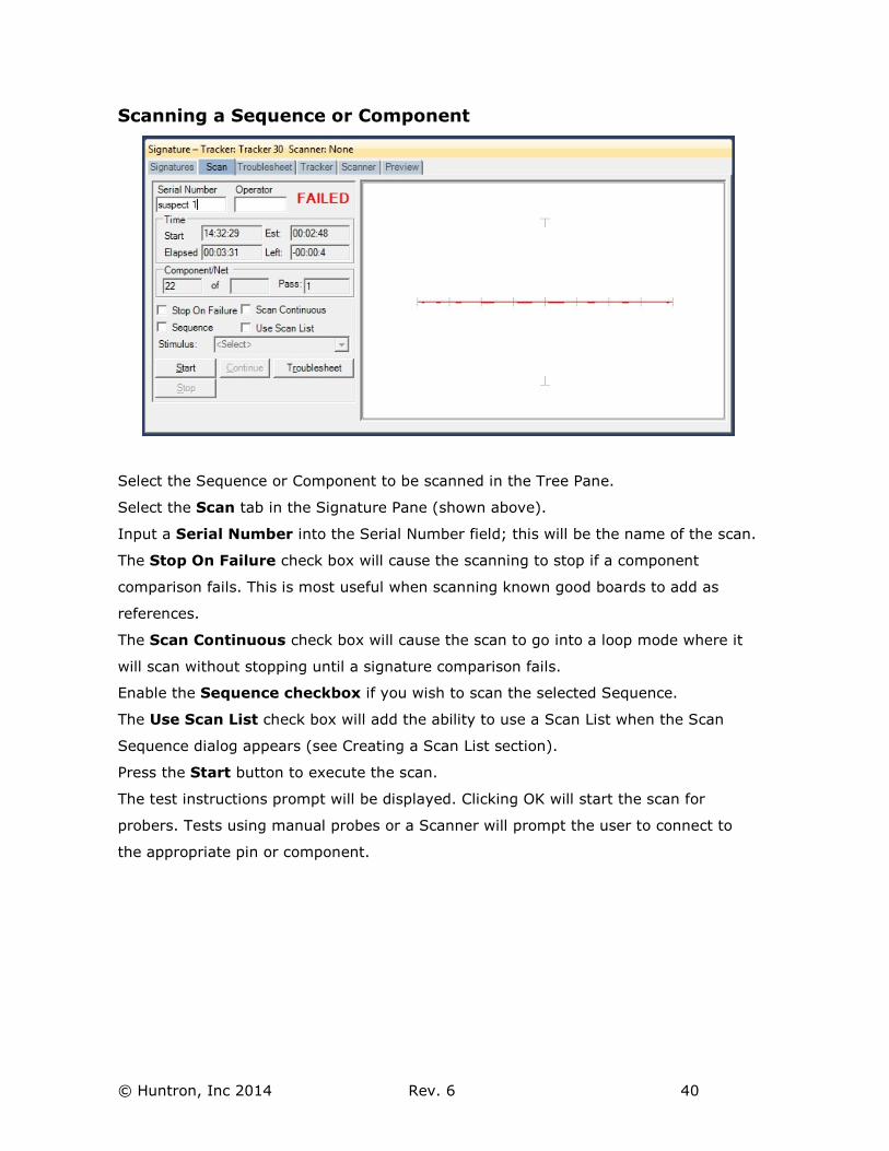
Scanning a Sequence or Component
Select the Sequence or Component to be scanned in the Tree Pane.
Select the Scan tab in the Signature Pane (shown above).
Input a Serial Number into the Serial Number field; this will be the name of the scan.
The Stop On Failure check box will cause the scanning to stop if a component
comparison fails. This is most useful when scanning known good boards to add as
references.
The Scan Continuous check box will cause the scan to go into a loop mode where it
will scan without stopping until a signature comparison fails.
Enable the Sequence checkbox if you wish to scan the selected Sequence.
The Use Scan List check box will add the ability to use a Scan List when the Scan
Sequence dialog appears (see Creating a Scan List section).
Press the Start button to execute the scan.
The test instructions prompt will be displayed. Clicking OK will start the scan for
probers. Tests using manual probes or a Scanner will prompt the user to connect to
the appropriate pin or component.
© Huntron, Inc 2014 Rev. 6 41
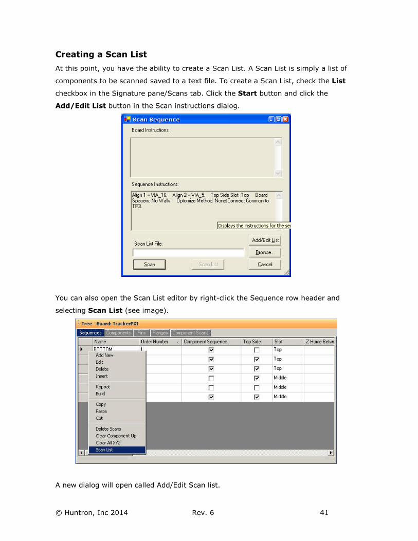
Creating a Scan List
At this point, you have the ability to create a Scan List. A Scan List is simply a list of
components to be scanned saved to a text file. To create a Scan List, check the List
checkbox in the Signature pane/Scans tab. Click the Start button and click the
Add/Edit List button in the Scan instructions dialog.
You can also open the Scan List editor by right-click the Sequence row header and
selecting Scan List (see image).
A new dialog will open called Add/Edit Scan list.
© Huntron, Inc 2014 Rev. 6 42
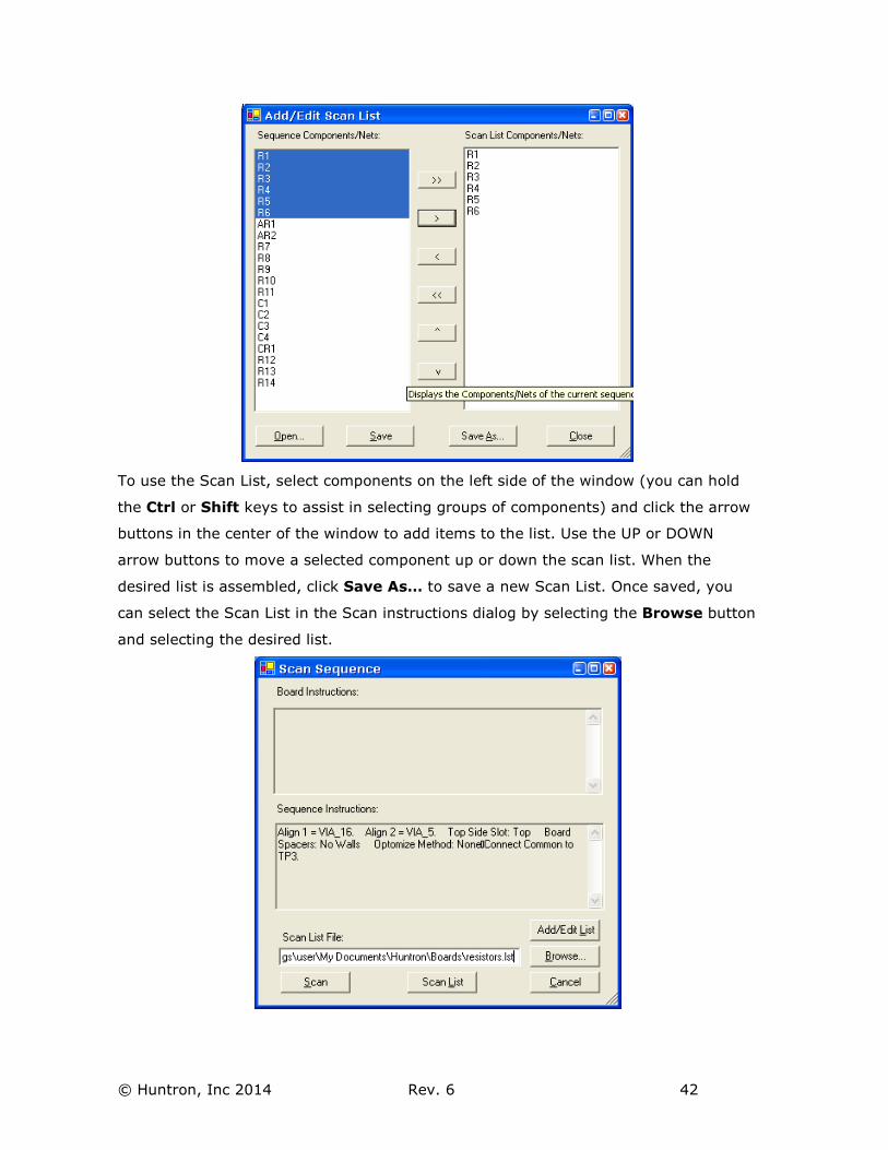
To use the Scan List, select components on the left side of the window (you can hold
the Ctrl or Shift keys to assist in selecting groups of components) and click the arrow
buttons in the center of the window to add items to the list. Use the UP or DOWN
arrow buttons to move a selected component up or down the scan list. When the
desired list is assembled, click Save As… to save a new Scan List. Once saved, you
can select the Scan List in the Scan instructions dialog by selecting the Browse button
and selecting the desired list.
© Huntron, Inc 2014 Rev. 6 43
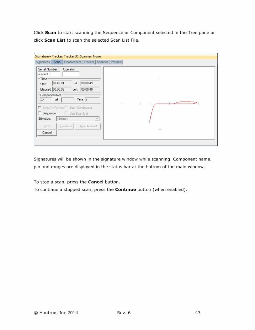
Click Scan to start scanning the Sequence or Component selected in the Tree pane or
click Scan List to scan the selected Scan List File.
Signatures will be shown in the signature window while scanning. Component name,
pin and ranges are displayed in the status bar at the bottom of the main window.
To stop a scan, press the Cancel button.
To continue a stopped scan, press the Continue button (when enabled).
© Huntron, Inc 2014 Rev. 6 44
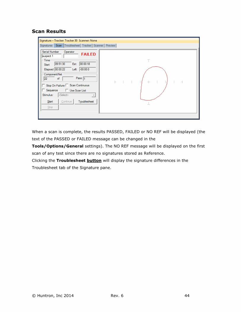
Scan Results
When a scan is complete, the results PASSED, FAILED or NO REF will be displayed (the
text of the PASSED or FAILED message can be changed in the
Tools/Options/General settings). The NO REF message will be displayed on the first
scan of any test since there are no signatures stored as Reference.
Clicking the Troublesheet button will display the signature differences in the
Troublesheet tab of the Signature pane.
© Huntron, Inc 2014 Rev. 6 45
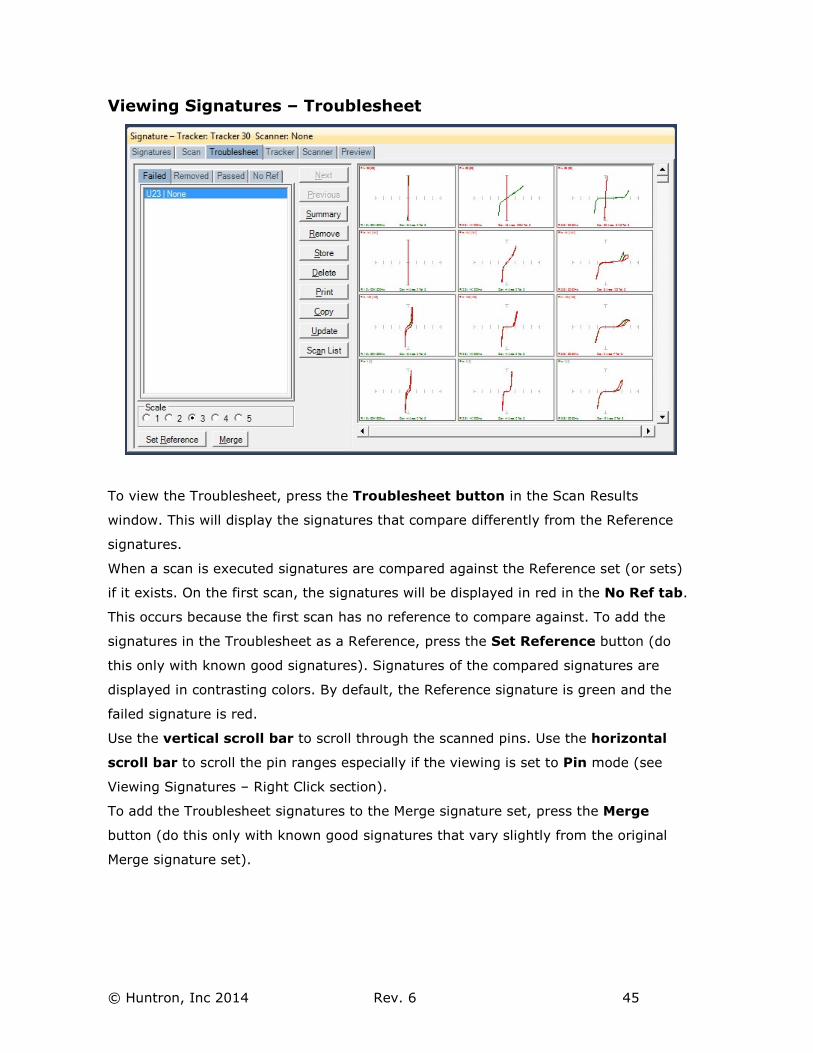
Viewing Signatures – Troublesheet
To view the Troublesheet, press the Troublesheet button in the Scan Results
window. This will display the signatures that compare differently from the Reference
signatures.
When a scan is executed signatures are compared against the Reference set (or sets)
if it exists. On the first scan, the signatures will be displayed in red in the No Ref tab.
This occurs because the first scan has no reference to compare against. To add the
signatures in the Troublesheet as a Reference, press the Set Reference button (do
this only with known good signatures). Signatures of the compared signatures are
displayed in contrasting colors. By default, the Reference signature is green and the
failed signature is red.
Use the vertical scroll bar to scroll through the scanned pins. Use the horizontal
scroll bar to scroll the pin ranges especially if the viewing is set to Pin mode (see
Viewing Signatures – Right Click section).
To add the Troublesheet signatures to the Merge signature set, press the Merge
button (do this only with known good signatures that vary slightly from the original
Merge signature set).

© Huntron, Inc 2014 Rev. 6 46
Viewing Signatures Troublesheet Report
To view and print the Troublesheet report, press the Print button in the Troublesheet
window. You can select from several options including a Sequence or Component Level
report, the level of detail and add problem and solution comments to the report. Click
Preview to view the report on-screen. The report can be printed or exported in
several different formats including HTML and PDF by selecting File/Export Document
in the Preview window.
© Huntron, Inc 2014 Rev. 6 47
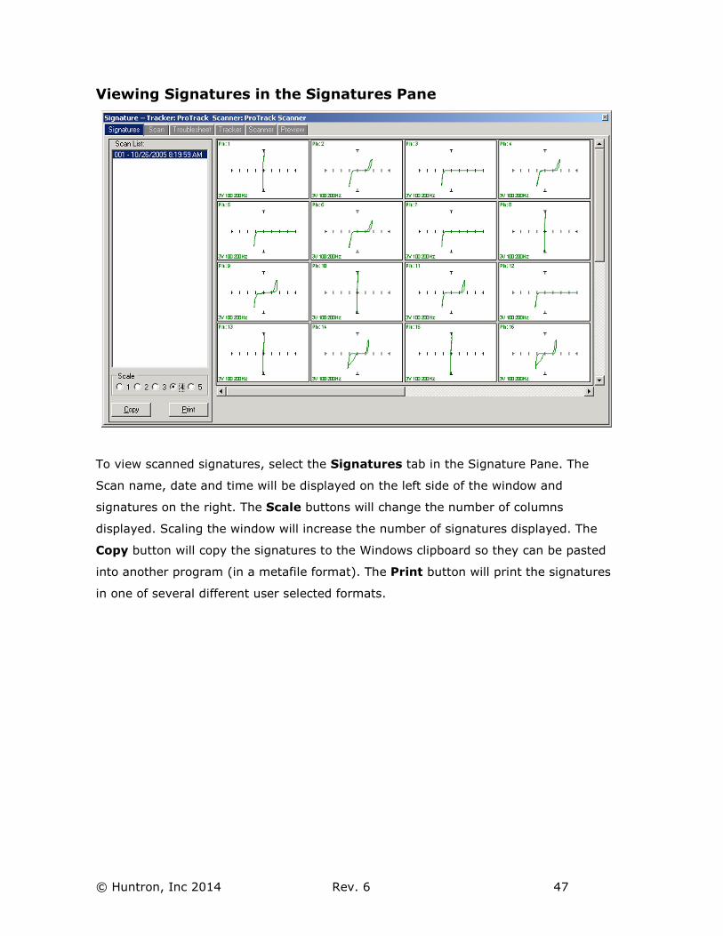
Viewing Signatures in the Signatures Pane
To view scanned signatures, select the Signatures tab in the Signature Pane. The
Scan name, date and time will be displayed on the left side of the window and
signatures on the right. The Scale buttons will change the number of columns
displayed. Scaling the window will increase the number of signatures displayed. The
Copy button will copy the signatures to the Windows clipboard so they can be pasted
into another program (in a metafile format). The Print button will print the signatures
in one of several different user selected formats.
© Huntron, Inc 2014 Rev. 6 48
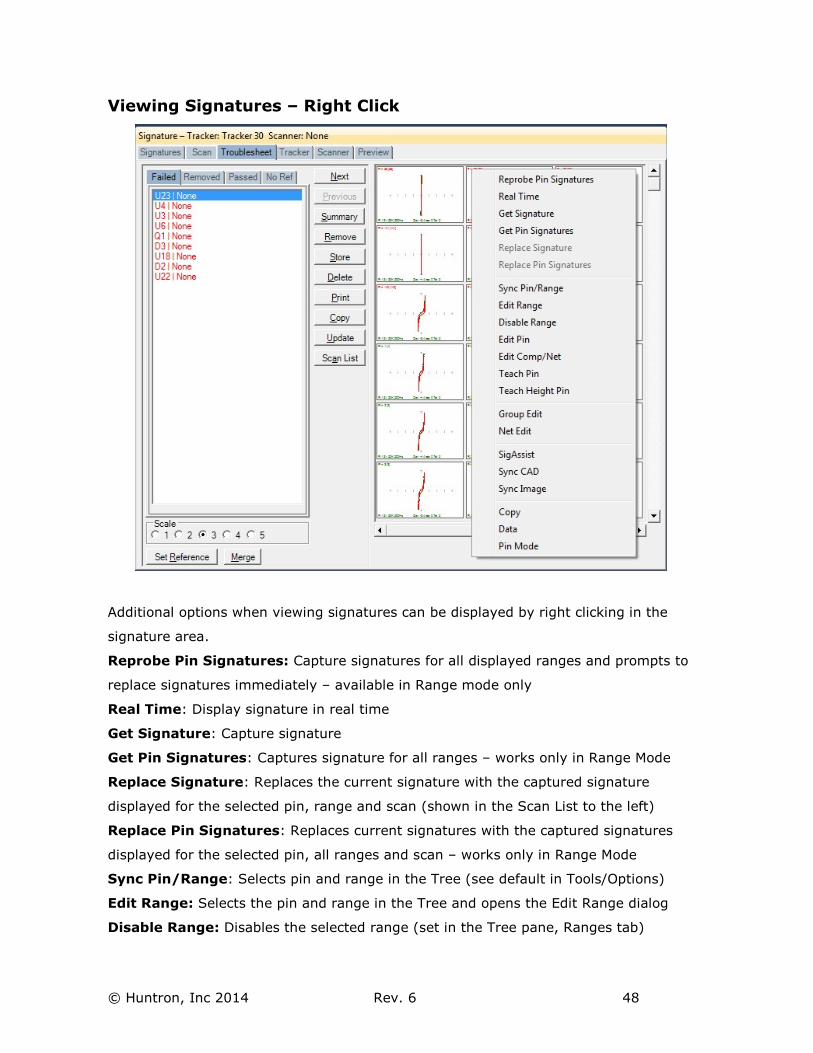
Viewing Signatures – Right Click
Additional options when viewing signatures can be displayed by right clicking in the
signature area.
Reprobe Pin Signatures: Capture signatures for all displayed ranges and prompts to
replace signatures immediately – available in Range mode only
Real Time: Display signature in real time
Get Signature: Capture signature
Get Pin Signatures: Captures signature for all ranges – works only in Range Mode
Replace Signature: Replaces the current signature with the captured signature
displayed for the selected pin, range and scan (shown in the Scan List to the left)
Replace Pin Signatures: Replaces current signatures with the captured signatures
displayed for the selected pin, all ranges and scan – works only in Range Mode
Sync Pin/Range: Selects pin and range in the Tree (see default in Tools/Options)
Edit Range: Selects the pin and range in the Tree and opens the Edit Range dialog
Disable Range: Disables the selected range (set in the Tree pane, Ranges tab)
© Huntron, Inc 2014 Rev. 6 49
Edit Pin: Selects the Pin the in the Tree and opens the Edit Pin dialog
Edit Comp/Net: Shortcut to the selected Component Edit dialog in the Tree pane
Teach Pin: Selects the pin the Prober Teach pane
Teach Height Pin: Selects the pin the Prober Teach Height pane
Group Edit: Opens Group Edit dialog for editing of component pin parameters as a
group
Net Edit: Opens Net Edit dialog for editing of Net pin parameters as a group
SigAssist: Displays the SigAssist window showing calculated approximate values of
resistance, capacitance, breakdown voltage, etc. based on signature information
Sync CAD: Will link the selected signature to the CAD image displayed in the
Image/CAD pane. Sync CAD will be disabled if there is no linked CAD data.
Sync Image: Links current Troublesheet to the image (image created by Access
Prober) in the Image pane/Image tab
Copy: Places the signature image in the clipboard
Data: Displays the signatures numeric data
Range/Pin Mode: Displays signatures with Range priority or Pin priority - see default
in Tools/Options)
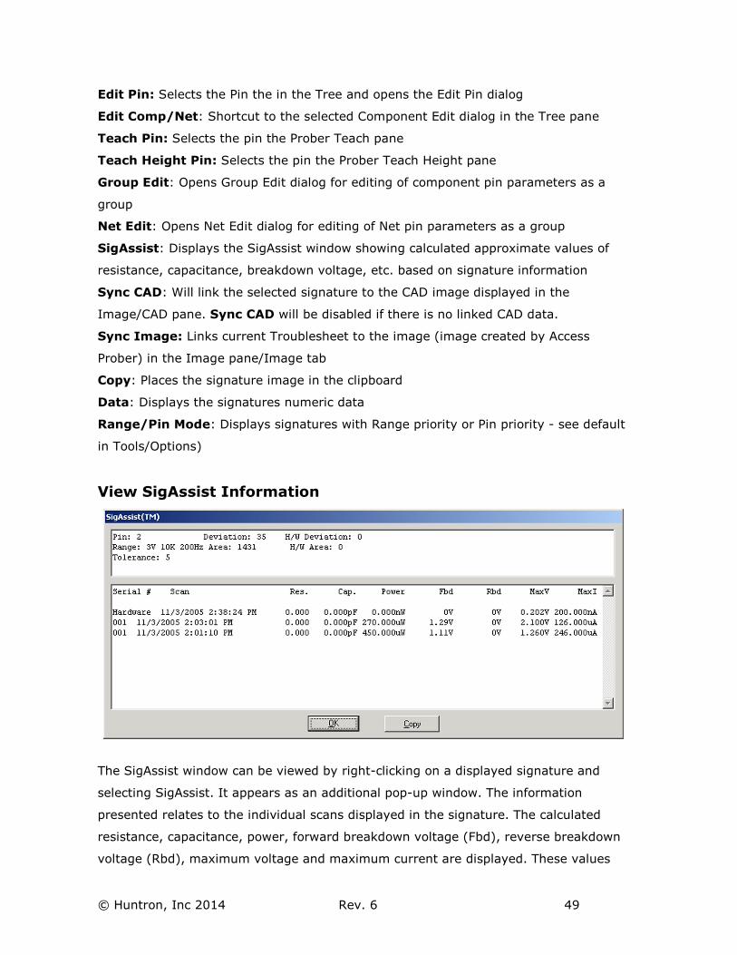
View SigAssist Information
The SigAssist window can be viewed by right-clicking on a displayed signature and
selecting SigAssist. It appears as an additional pop-up window. The information
presented relates to the individual scans displayed in the signature. The calculated
resistance, capacitance, power, forward breakdown voltage (Fbd), reverse breakdown
voltage (Rbd), maximum voltage and maximum current are displayed. These values
© Huntron, Inc 2014 Rev. 6 50
are for troubleshooting purposes only and are not intended to be used as true
measurements. The accuracy of the SigAssist values depends greatly on the scanned
signature information. SigAssist values may not be calculated for signatures that do
not contain enough information for reasonable calculations to take place (i.e. opens,
shorts). The Copy button will put a copy of the window into the clipboard for use in
other programs.
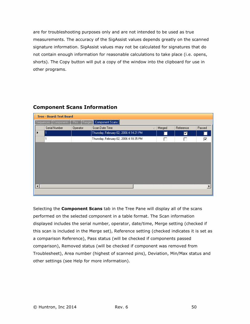
Component Scans Information
Selecting the Component Scans tab in the Tree Pane will display all of the scans
performed on the selected component in a table format. The Scan information
displayed includes the serial number, operator, date/time, Merge setting (checked if
this scan is included in the Merge set), Reference setting (checked indicates it is set as
a comparison Reference), Pass status (will be checked if components passed
comparison), Removed status (will be checked if component was removed from
Troublesheet), Area number (highest of scanned pins), Deviation, Min/Max status and
other settings (see Help for more information).
© Huntron, Inc 2014 Rev. 6 51
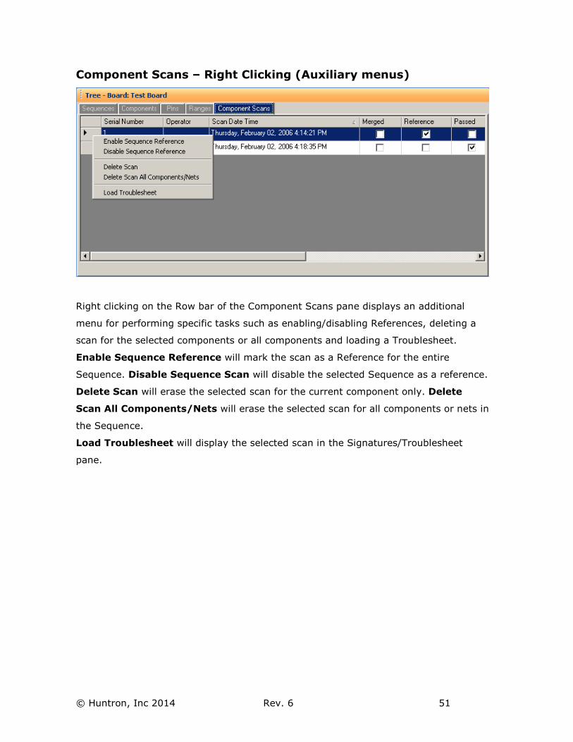
Component Scans – Right Clicking (Auxiliary menus)
Right clicking on the Row bar of the Component Scans pane displays an additional
menu for performing specific tasks such as enabling/disabling References, deleting a
scan for the selected components or all components and loading a Troublesheet.
Enable Sequence Reference will mark the scan as a Reference for the entire
Sequence. Disable Sequence Scan will disable the selected Sequence as a reference.
Delete Scan will erase the selected scan for the current component only. Delete
Scan All Components/Nets will erase the selected scan for all components or nets in
the Sequence.
Load Troublesheet will display the selected scan in the Signatures/Troublesheet
pane.
© Huntron, Inc 2014 Rev. 6 52
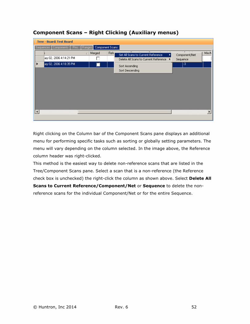
Component Scans – Right Clicking (Auxiliary menus)
Right clicking on the Column bar of the Component Scans pane displays an additional
menu for performing specific tasks such as sorting or globally setting parameters. The
menu will vary depending on the column selected. In the image above, the Reference
column header was right-clicked.
This method is the easiest way to delete non-reference scans that are listed in the
Tree/Component Scans pane. Select a scan that is a non-reference (the Reference
check box is unchecked) the right-click the column as shown above. Select Delete All
Scans to Current Reference/Component/Net or Sequence to delete the non-
reference scans for the individual Component/Net or for the entire Sequence.
© Huntron, Inc 2014 Rev. 6 53
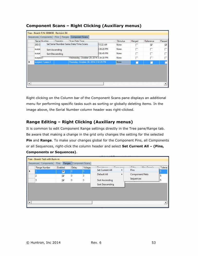
Component Scans – Right Clicking (Auxiliary menus)
Right clicking on the Column bar of the Component Scans pane displays an additional
menu for performing specific tasks such as sorting or globally deleting items. In the
image above, the Serial Number column header was right-clicked.
Range Editing – Right Clicking (Auxiliary menus)
It is common to edit Component Range settings directly in the Tree pane/Range tab.
Be aware that making a change in the grid only changes the setting for the selected
Pin and Range. To make your changes global for the Component Pins, all Components
or all Sequences, right-click the column header and select Set Current All – (Pins,
Components or Sequences).
© Huntron, Inc 2014 Rev. 6 54
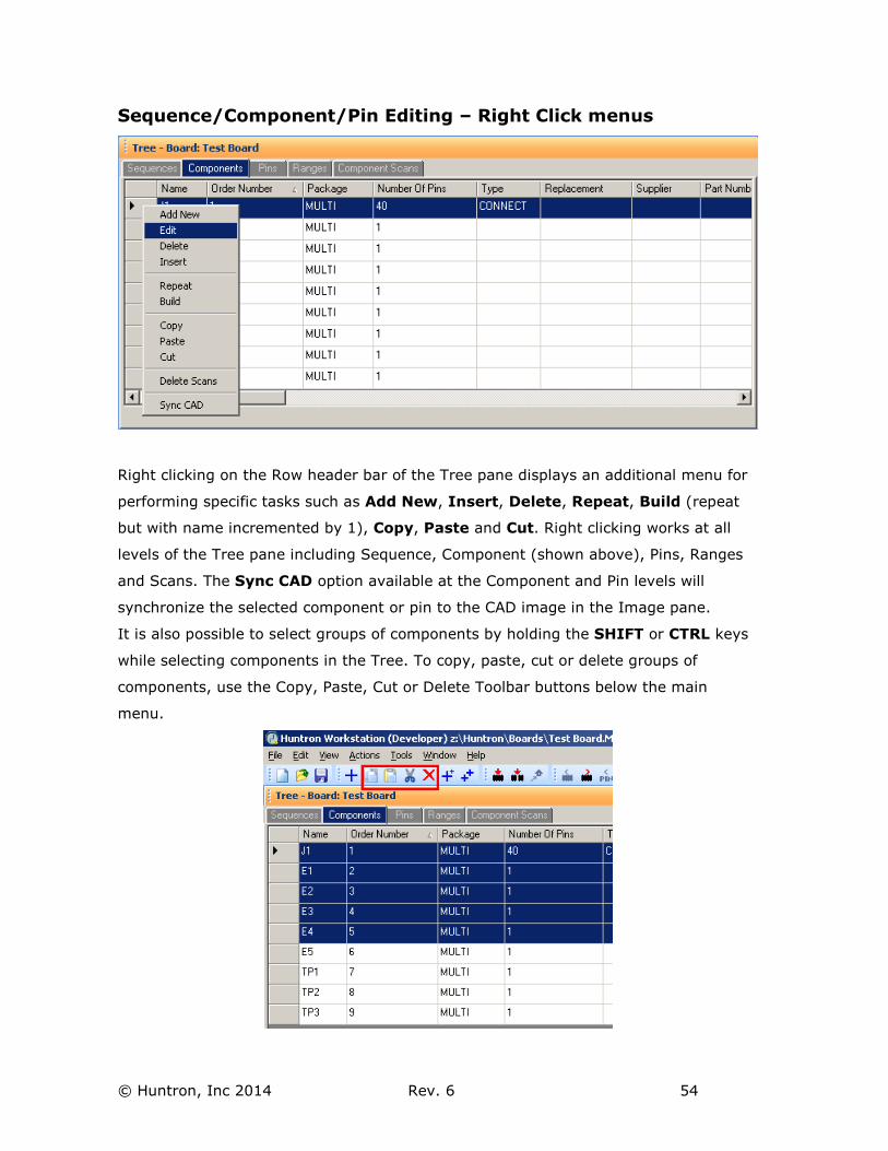
Sequence/Component/Pin Editing – Right Click menus
Right clicking on the Row header bar of the Tree pane displays an additional menu for
performing specific tasks such as Add New, Insert, Delete, Repeat, Build (repeat
but with name incremented by 1), Copy, Paste and Cut. Right clicking works at all
levels of the Tree pane including Sequence, Component (shown above), Pins, Ranges
and Scans. The Sync CAD option available at the Component and Pin levels will
synchronize the selected component or pin to the CAD image in the Image pane.
It is also possible to select groups of components by holding the SHIFT or CTRL keys
while selecting components in the Tree. To copy, paste, cut or delete groups of
components, use the Copy, Paste, Cut or Delete Toolbar buttons below the main
menu.
© Huntron, Inc 2014 Rev. 6 55
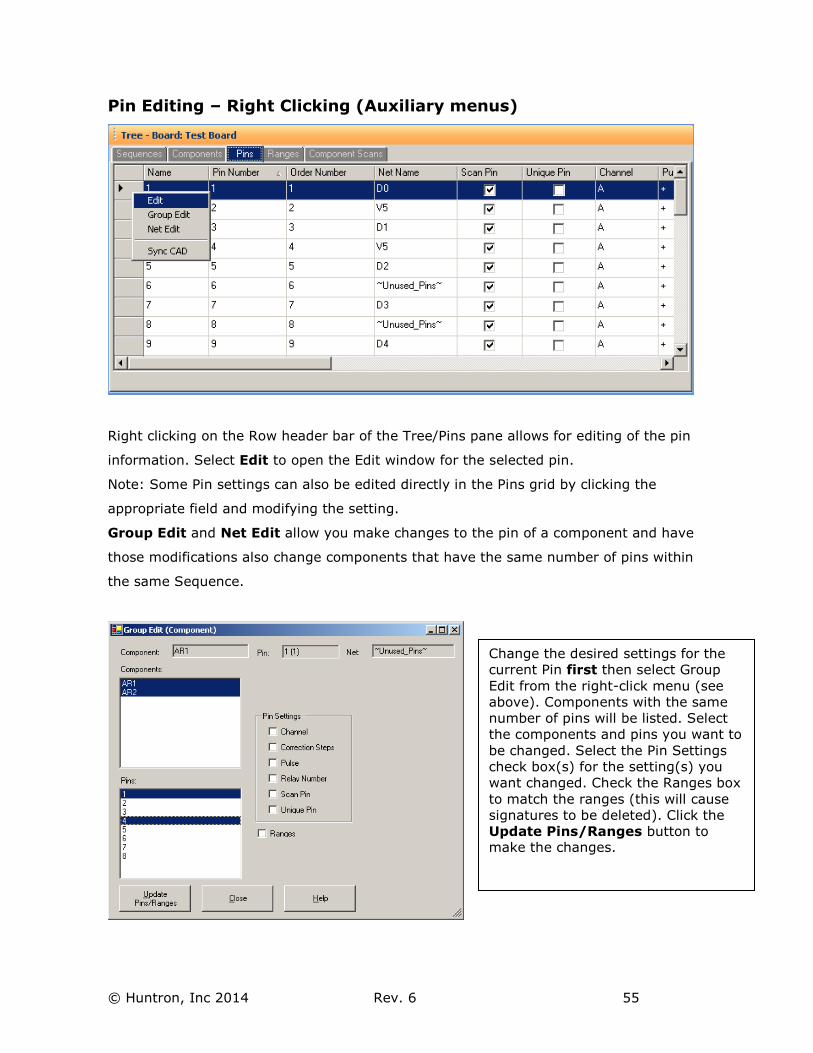
Pin Editing – Right Clicking (Auxiliary menus)
Right clicking on the Row header bar of the Tree/Pins pane allows for editing of the pin
information. Select Edit to open the Edit window for the selected pin.
Note: Some Pin settings can also be edited directly in the Pins grid by clicking the
appropriate field and modifying the setting.
Group Edit and Net Edit allow you make changes to the pin of a component and have
those modifications also change components that have the same number of pins within
the same Sequence.
Change the desired settings for the
current Pin first then select Group
Edit from the right-click menu (see
above). Components with the same
number of pins will be listed. Select
the components and pins you want to
be changed. Select the Pin Settings
check box(s) for the setting(s) you
want changed. Check the Ranges box
to match the ranges (this will cause
signatures to be deleted). Click the
Update Pins/Ranges button to make the changes.
© Huntron, Inc 2014 Rev. 6 56
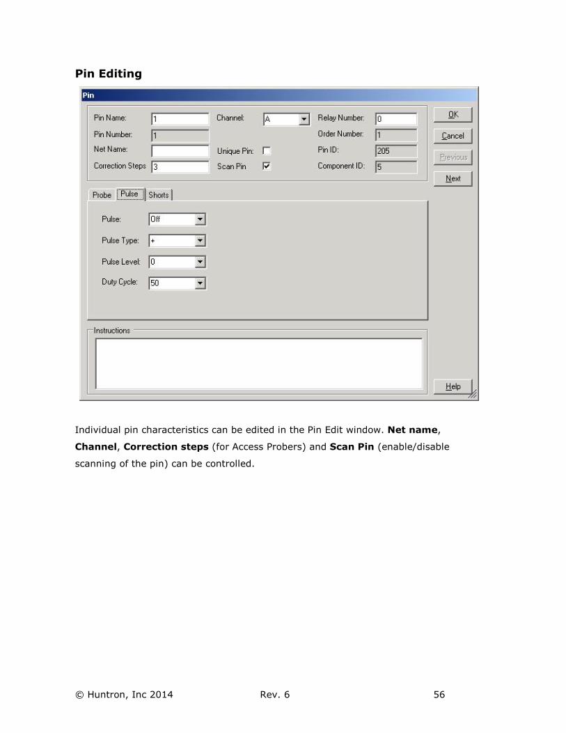
Pin Editing
Individual pin characteristics can be edited in the Pin Edit window. Net name,
Channel, Correction steps (for Access Probers) and Scan Pin (enable/disable
scanning of the pin) can be controlled.

© Huntron, Inc 2014 Rev. 6 57
Adding CAD data in the Image Pane
CAD data can be displayed by selecting the CAD tab in the Image Pane. Before the
board layout can be displayed, a .CC (CAMCAD) file must be loaded. This is
accomplished in the Board Edit window by clicking the “Load CC…” button and
browsing to the associated CADCAM file. Once selected, the board layout will appear in
the Image/CAD Pane.
The Board button sets the zoom level to view the entire board. Window allows you to
use a drag box in the CAD image to zoom in on a selected location. Flip Board
displays the other side of the board. Options displays the Layer selection window.
Clear unselects any highlighted components or nets.
The CAD information is automatically loaded if the test was created using CAD data or
if File/Convert was used to convert a test created in version 3.X that had CAD data
attached.
© Huntron, Inc 2014 Rev. 6 58
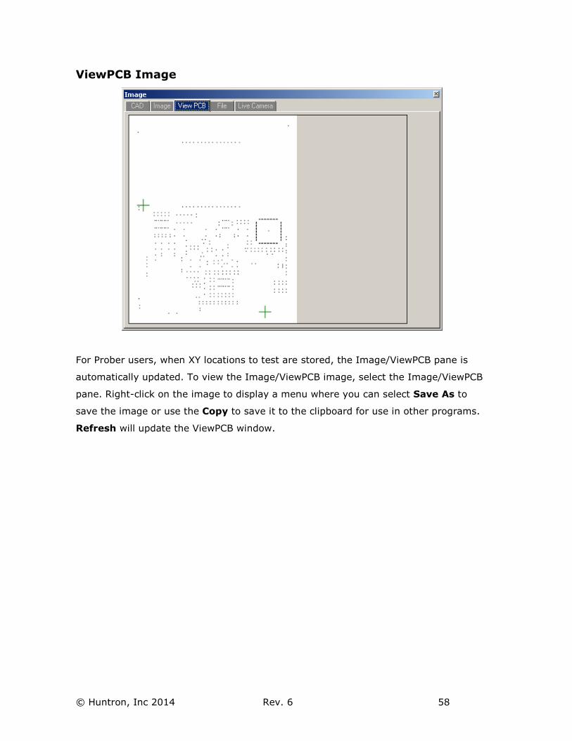
ViewPCB Image
For Prober users, when XY locations to test are stored, the Image/ViewPCB pane is
automatically updated. To view the Image/ViewPCB image, select the Image/ViewPCB
pane. Right-click on the image to display a menu where you can select Save As to
save the image or use the Copy to save it to the clipboard for use in other programs.
Refresh will update the ViewPCB window.
© Huntron, Inc 2014 Rev. 6 59
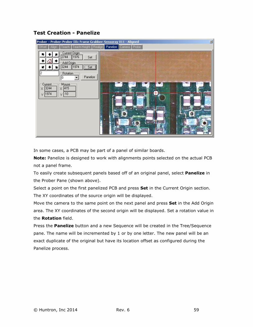
Test Creation - Panelize
In some cases, a PCB may be part of a panel of similar boards.
Note: Panelize is designed to work with alignments points selected on the actual PCB
not a panel frame.
To easily create subsequent panels based off of an original panel, select Panelize in
the Prober Pane (shown above).
Select a point on the first panelized PCB and press Set in the Current Origin section.
The XY coordinates of the source origin will be displayed.
Move the camera to the same point on the next panel and press Set in the Add Origin
area. The XY coordinates of the second origin will be displayed. Set a rotation value in
the Rotation field.
Press the Panelize button and a new Sequence will be created in the Tree/Sequence
pane. The name will be incremented by 1 or by one letter. The new panel will be an
exact duplicate of the original but have its location offset as configured during the
Panelize process.
© Huntron, Inc 2014 Rev. 6 60
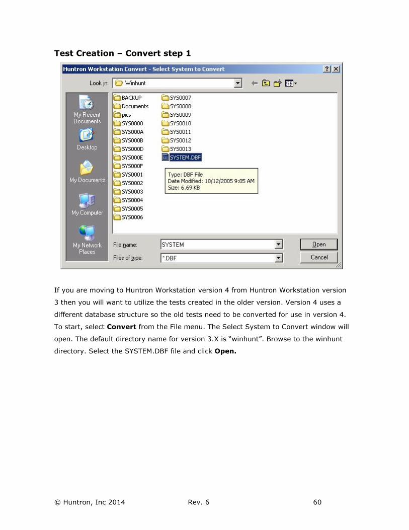
Test Creation – Convert step 1
If you are moving to Huntron Workstation version 4 from Huntron Workstation version
3 then you will want to utilize the tests created in the older version. Version 4 uses a
different database structure so the old tests need to be converted for use in version 4.
To start, select Convert from the File menu. The Select System to Convert window will
open. The default directory name for version 3.X is “winhunt”. Browse to the winhunt
directory. Select the SYSTEM.DBF file and click Open.
© Huntron, Inc 2014 Rev. 6 61
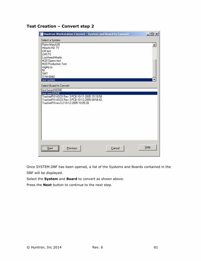
Test Creation – Convert step 2
Once SYSTEM.DBF has been opened, a list of the Systems and Boards contained in the
DBF will be displayed.
Select the System and Board to convert as shown above.
Press the Next button to continue to the next step.
© Huntron, Inc 2014 Rev. 6 62
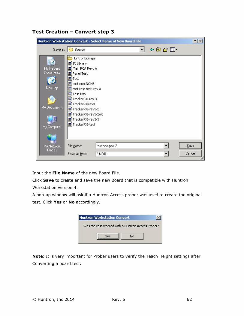
Test Creation – Convert step 3
Input the File Name of the new Board File.
Click Save to create and save the new Board that is compatible with Huntron
Workstation version 4.
A pop-up window will ask if a Huntron Access prober was used to create the original
test. Click Yes or No accordingly.
Note: It is very important for Prober users to verify the Teach Height settings after
Converting a board test.
© Huntron, Inc 2014 Rev. 6 63
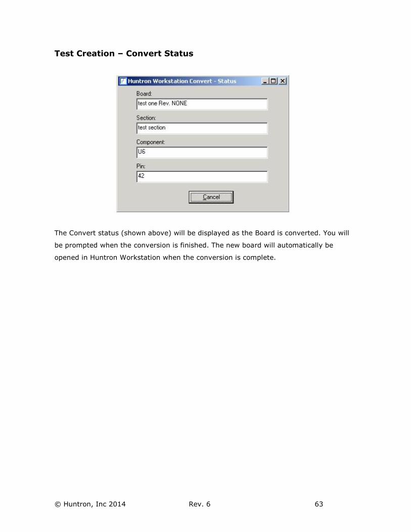
Test Creation – Convert Status
The Convert status (shown above) will be displayed as the Board is converted. You will
be prompted when the conversion is finished. The new board will automatically be
opened in Huntron Workstation when the conversion is complete.
© Huntron, Inc 2014 Rev. 6 64
Huntron Workstation Buttons Feature
Huntron Workstation has a built-in feature that allows any Windows based program to
be started by clicking a button in the Workstation toolbar. It is very easy to use and a
“Button” can be attached to any Board, Sequence or Component/Net. In this example,
a Button will be created for a Sequence but the process is the same for the Board and
Component/Net levels.
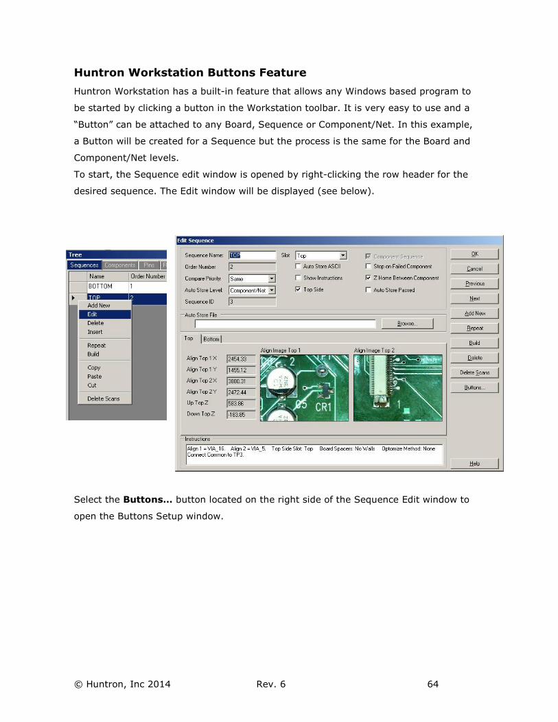
To start, the Sequence edit window is opened by right-clicking the row header for the
desired sequence. The Edit window will be displayed (see below).
Select the Buttons… button located on the right side of the Sequence Edit window to
open the Buttons Setup window.
© Huntron, Inc 2014 Rev. 6 65
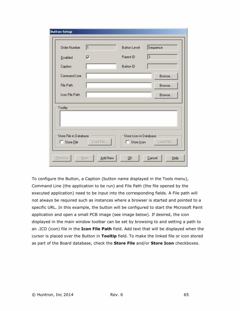
To configure the Button, a Caption (button name displayed in the Tools menu),
Command Line (the application to be run) and File Path (the file opened by the
executed application) need to be input into the corresponding fields. A File path will
not always be required such as instances where a browser is started and pointed to a
specific URL. In this example, the button will be configured to start the Microsoft Paint
application and open a small PCB image (see image below). If desired, the icon
displayed in the main window toolbar can be set by browsing to and setting a path to
an .ICO (icon) file in the Icon File Path field. Add text that will be displayed when the
cursor is placed over the Button in Tooltip field. To make the linked file or icon stored
as part of the Board database, check the Store File and/or Store Icon checkboxes.
© Huntron, Inc 2014 Rev. 6 66
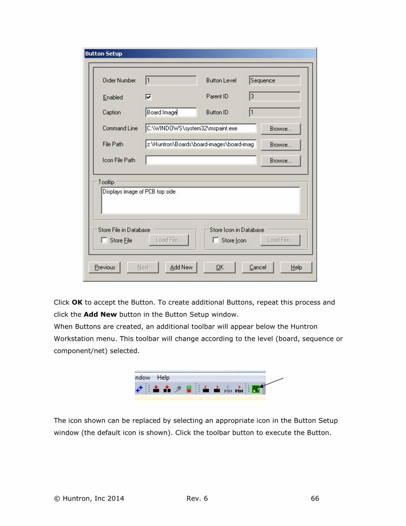
Click OK to accept the Button. To create additional Buttons, repeat this process and
click the Add New button in the Button Setup window.
When Buttons are created, an additional toolbar will appear below the Huntron
Workstation menu. This toolbar will change according to the level (board, sequence or
component/net) selected.
The icon shown can be replaced by selecting an appropriate icon in the Button Setup
window (the default icon is shown). Click the toolbar button to execute the Button.
© Huntron, Inc 2014 Rev. 6 67
Technical Support
For questions or assistance in using Huntron Workstation, contact Huntron at
800-426-9265, 425-743-3171 or email [email protected].
There is online assistance for Huntron Workstation at
www.huntron.com/support/workstation.htm. This page will contains software updates,
a form for reporting software issues and updates to documentation such as this
tutorial.