HUNTER WATER CORPORATION WATER AND SEWER DESIGN MANUAL ... · All Renumbered to be consistent with...
48
HUNTER WATER CORPORATION WATER AND SEWER DESIGN MANUAL SECTION 7 TANK / RESERVOIR STANDARDS
Transcript of HUNTER WATER CORPORATION WATER AND SEWER DESIGN MANUAL ... · All Renumbered to be consistent with...

HUNTER WATER CORPORATION
WATER AND SEWERDESIGN MANUAL
SECTION 7TANK / RESERVOIR STANDARDS
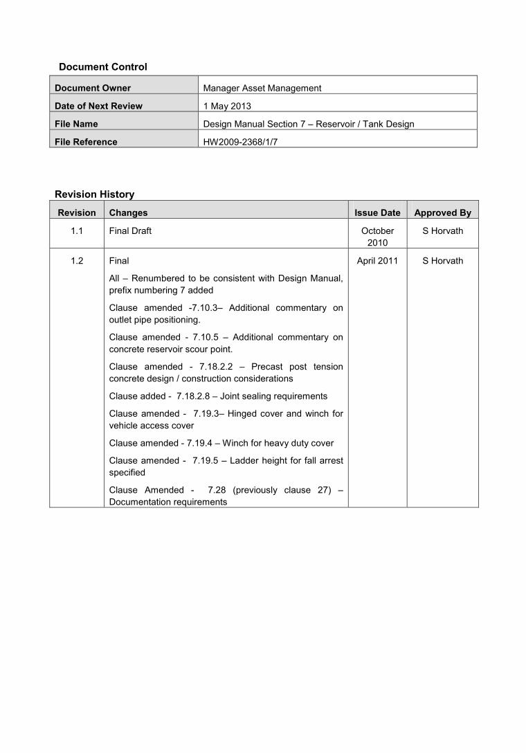
Document Control
Document Owner Manager Asset Management
Date of Next Review 1 May 2013
File Name Design Manual Section 7 – Reservoir / Tank Design
File Reference HW2009-2368/1/7
Revision History
Revision Changes Issue Date Approved By
1.1 Final Draft October2010
S Horvath
1.2 Final
All – Renumbered to be consistent with Design Manual,prefix numbering 7 added
Clause amended -7.10.3– Additional commentary onoutlet pipe positioning.
Clause amended - 7.10.5 – Additional commentary onconcrete reservoir scour point.
Clause amended - 7.18.2.2 – Precast post tensionconcrete design / construction considerations
Clause added - 7.18.2.8 – Joint sealing requirements
Clause amended - 7.19.3– Hinged cover and winch forvehicle access cover
Clause amended - 7.19.4 – Winch for heavy duty cover
Clause amended - 7.19.5 – Ladder height for fall arrestspecified
Clause Amended - 7.28 (previously clause 27) –Documentation requirements
April 2011 S Horvath
SECTION 7 TANK / RESERVOIR STANDARD HUNTER WATER CORPORATIONMay 2011
a
TABLE OF CONTENTS
7.1 Introduction................................................................................................................................ 47.1.1 General ................................................................................................................................ 47.1.2 Design Objectives ................................................................................................................ 4
7.2 Construction Methodology ....................................................................................................... 57.3 Location ...................................................................................................................................... 57.4 Land Selection ........................................................................................................................... 67.5 Location Factors........................................................................................................................ 67.6 Easements .................................................................................................................................. 87.7 Site Survey ................................................................................................................................. 87.8 Geotechnical .............................................................................................................................. 87.9 Road Access .............................................................................................................................. 87.10 Hydraulic Design ....................................................................................................................... 9
7.10.1 Inlet Pipework ...................................................................................................................... 97.10.2 Automatic Inlet Valves (Aiv)................................................................................................. 97.10.3 Outlet Pipework.................................................................................................................... 97.10.4 Overflow............................................................................................................................... 97.10.5 Scour / Washout Bulkhead ................................................................................................ 107.10.6 Washdown Hydrant ........................................................................................................... 107.10.7 Site Discharge Structure.................................................................................................... 10
7.11 Water Quality Aspects............................................................................................................. 107.11.1 Mixing Of Storage .............................................................................................................. 107.11.2 Ventilation / Vermin Proofing Details ................................................................................. 117.11.3 Inlet Nozzles ...................................................................................................................... 117.11.4 Re-Chlorination .................................................................................................................. 117.11.5 Stormwater Management Details ...................................................................................... 11
7.12 Boundary Fencing ................................................................................................................... 127.13 Landscaping............................................................................................................................. 127.14 Design Life................................................................................................................................ 127.15 Whole Of Life Costs................................................................................................................. 137.16 Durability .................................................................................................................................. 13
7.16.1 Thermal Effects.................................................................................................................. 147.16.2 Dissimilar Metals................................................................................................................ 14
7.17 Preferred Equipment List........................................................................................................ 147.18 Structural Design..................................................................................................................... 15
7.18.1 Fabricated Mild Steel ......................................................................................................... 157.18.2 Reinforced Concrete Tanks (Cast In-Situ & Pre-Cast) ...................................................... 15
7.18.2.1 Cast In-Situ............................................................................................................................167.18.2.2 Pre-Cast Post Tensioned ....................................................................................................167.18.2.3 Concrete Mix Design Requirements..................................................................................167.18.2.4 Aggregates ............................................................................................................................177.18.2.5 Addition Of Water .................................................................................................................177.18.2.6 Chemical Admixtures ...........................................................................................................177.18.2.7 Cover Requirements ............................................................................................................177.18.2.8 Joint Sealing..........................................................................................................................187.18.2.9 Concrete Repairs..................................................................................................................187.18.2.10 Watertightness Test .............................................................................................................18
7.18.3 Bolted Steel Tanks............................................................................................................. 187.19 Roof Access ............................................................................................................................. 18

SECTION 7 TANK / RESERVOIR STANDARD HUNTER WATER CORPORATIONMay 2011
b
7.19.1 Roof Access Stairs ............................................................................................................ 187.19.2 Roof Platform ..................................................................................................................... 197.19.3 Maintenance Access Vehicle Hatch .................................................................................. 197.19.4 Roof Access Hatch ............................................................................................................ 197.19.5 Internal Ladder................................................................................................................... 197.19.6 Eyebolts ............................................................................................................................. 207.19.7 Davit And Lifting Gear........................................................................................................ 20
7.20 Wall Strake Access (Fabricated Steel Only) ......................................................................... 207.20.1 Personnel Access Hatches................................................................................................ 207.20.2 Ventilation Hatch................................................................................................................ 20
7.21 Steel Floor Plates..................................................................................................................... 217.22 Columns.................................................................................................................................... 217.23 Sampling Arrangement ........................................................................................................... 217.24 Reservoir Testing .................................................................................................................... 21
7.24.1 General .............................................................................................................................. 217.24.2 Mild Steel Fabricated Tanks .............................................................................................. 21
7.24.2.1 Floor Testing .........................................................................................................................217.24.2.2 Wall Testing...........................................................................................................................22
7.24.3 Foundations ....................................................................................................................... 227.24.4 Hydrostatic Testing ............................................................................................................ 227.24.5 Overflow / Scour ................................................................................................................ 22
7.25 Coating Systems For Fabricated Steel Tanks ...................................................................... 227.25.1 General .............................................................................................................................. 227.25.2 Surface Preparation........................................................................................................... 23
7.25.2.1 Procedure ..............................................................................................................................237.25.2.2 Abrasive Material..................................................................................................................23
7.25.3 Coating Materials ............................................................................................................... 237.25.3.1 Reservoir Internal Surfaces ................................................................................................237.25.3.2 External Surfaces (Coastal Tank <5km To The Coast) ..................................................247.25.3.3 External Surfaces (Inland Tank >5km To Coast) ............................................................24
7.26 Cathodic Protection (Cp) System .......................................................................................... 247.26.1 General .............................................................................................................................. 247.26.2 Location Of Facilities ......................................................................................................... 247.26.3 Anodes............................................................................................................................... 247.26.4 Electrodes .......................................................................................................................... 257.26.5 Test Point........................................................................................................................... 267.26.6 Cabling............................................................................................................................... 26
7.27 Electrical ................................................................................................................................... 267.27.1 Power Supply..................................................................................................................... 267.27.2 Switchboard ....................................................................................................................... 26
7.27.2.1 Metering of Incoming Power Supply..................................................................................277.27.2.2 PLC Telemetry and Instrumentation Cubicle ...................................................................277.27.2.3 Radio Path Survey ...............................................................................................................27
7.27.3 Level Instruments .............................................................................................................. 287.27.4 Security .............................................................................................................................. 287.27.5 Lighting .............................................................................................................................. 287.27.6 Site 230v Gpos .................................................................................................................. 287.27.7 Lightning Protection ........................................................................................................... 28
7.28 Design Documentation And Drawings .................................................................................. 297.28.1 Design Design.................................................................................................................... 297.28.2 Electrical Design ................................................................................................................ 297.28.3 Operating And Maintenance .............................................................................................. 29
SECTION 7 TANK / RESERVOIR STANDARD HUNTER WATER CORPORATIONMay 2011
c
TABLES
Table 1 Planning and Design Factors for Reservoirs.............................................................................. 5Table 2 Location Factors ......................................................................................................................... 7Table 3 Asset Design Life...................................................................................................................... 12Table 4 Coastal Tank Material Requirements (<5km from coast)......................................................... 13Table 5 Inland Tank Material Requirements (>5km from coast) ........................................................... 14Table 6 Concrete Mix Requirements ..................................................................................................... 16Table 7 Minimum Concrete Cover......................................................................................................... 17
APPENDICES
Appendix A - Tank / Reservoir Standard Drawings

7.1 INTRODUCTION
7.1.1 GENERALThe objective of this document is to standardise and reduce the variability in tank / reservoirdesigns undertaken for and behalf of the Corporation.
This document sets out to provide guidance by way of general principles, criteria and goodpractice. This document shall be looked upon as being applicable in the majority ofsituations and should be read in conjunction with Hunter Water Standard TechnicalSpecifications and Drawings.
Also provided are typical layout and arrangement drawings, which detail the minimumdesign, operational and maintenance requirements.
Where the word ‘reservoir’ is used in this document, it should also be read as applicable to‘tank’ for use on other storages such as reclaimed water tanks and clear water tanks etc.
The Corporations reservoirs are normally taken offline as part of a programmed cleaning andmaintenance schedule, therefore reducing the requirement for diver access on a regularbasis.
This document does not relieve the designer’s responsibility for compliance with relevantAustralian and International standards and use sound engineering judgement for all aspectsof the design. The designer must justify in a designers report any variation from theminimum requirements set out in this document.
7.1.2 DESIGN OBJECTIVESIn principle, the reservoir design objectives are to achieve the following criteria: the reservoir is to be functional ensure ease of maintenance ensure reliable operation ensure fitness for purpose ensure water quality is not degraded ensure ease of constructability minimise adverse environmental and community impact comply with environmental requirements comply with OH&S requirements minimise energy consumption by efficient operation achieve extended service life with minimal maintenance and least whole of life cost. provide adequate weather protection and stormwater management provide adequate ventilation to minimise corrosion provide sufficient vehicular and personnel access for maintenance
Installations are to be planned and designed with particular reference to the followingpractice:

SECTION 7 TANK / RESERVOIR STANDARD HUNTER WATER CORPORATIONMay 2011 5
Table 1 Planning and Design Factors for Reservoirs
Factors Requirements
Efficiently receive store and deliver
Maintain water quality
Operation to comply with the requirements outlined in the HWC Waterand Sewer Design Manual
Meet regulatory requirements
Have minimum visual impact on neighbourhood
Incorporate remote monitoring, control and telemetry alarms
Functionality
Provide safe working conditions for operation and maintenancepersonnel
Be designed for minimal operator attendance and low maintenance
Be easily maintained using standard maintenance practices
Incorporate features to allow for flexibility of operation
Maintainability
Utilise standard components that are readily available andinterchangeable
Operate reliably, effectively and automatically (i.e. normallyunattended)
Have redundancy so that failure of any one item shall not cause totalfailure
Reliability
Incorporate adequate security measures
7.2 CONSTRUCTION METHODOLOGYThe following reservoir construction methods are acceptable: Fabricated Mild Steel Cast In-situ Reinforced Concrete Pre-cast Post Tensioned Concrete
Where the reservoir is founded on sound rock all of the above options are acceptable.
For sites where the reservoir is to be founded on residual soils, or is subject to potentialdifferential settlement or is located within a mine subsidence area, provide fabricated mildsteel only. Consideration may be given to acceptability of concrete reservoirs whereappropriate foundation treatment such as piling is adopted.
To reduce the OHS risks of confined space entry via the roof platform, there is a preferencefor fabricated mild steel tanks with side wall hatch access to the reservoir for cleaning andmaintenance activities.
7.3 LOCATIONThe location of a reservoir is strongly influenced by hydraulic considerations so that thenetwork can operate satisfactorily under the design demand conditions.

SECTION 7 TANK / RESERVOIR STANDARD HUNTER WATER CORPORATIONMay 2011 6
The location shall be selected so that water pressure to consumers meets Hunter Water’scriteria.
Given normal latitude, the choice of site is usually determined by land availability andaesthetic conditions, but the location should allow for a suitable layout for the inlet / outlet,scour, overflow pipework and discharge structure.
To ensure that the proposed reservoir location and layout are acceptable, the proposed siteshall be approved in advance by Hunter Water.
7.4 LAND SELECTIONThe order of preference for land choice for a reservoir site shall be: Land provided within the development by the person or business that is developing the
land or their agent. (Hunter Water is to be given title or easement rights) Hunter Water owned land (if Hunter Water is the developer) Council land (Community land/Operational land) Vacant Crown land. Established private property Vacant private property Established Crown land Road reserve
Obtain easement rights or freehold title (vested in Hunter Water) for any reservoir sites,access and services. The reservoir shall be contained within an easement if wholly within apublic reserve or a designated lot if not within a public reserve. The easement or lot is toinclude batters, embankments and retaining walls. Access and services should be containedwithin an easement.
Consideration should also be given to the potential likelihood of future development to enablea future storage of similar size within the site footprint.
7.5 LOCATION FACTORSThe following factors shall be considered during the site selection process:
SECTION 7 TANK / RESERVOIR STANDARD HUNTER WATER CORPORATIONMay 2011 7
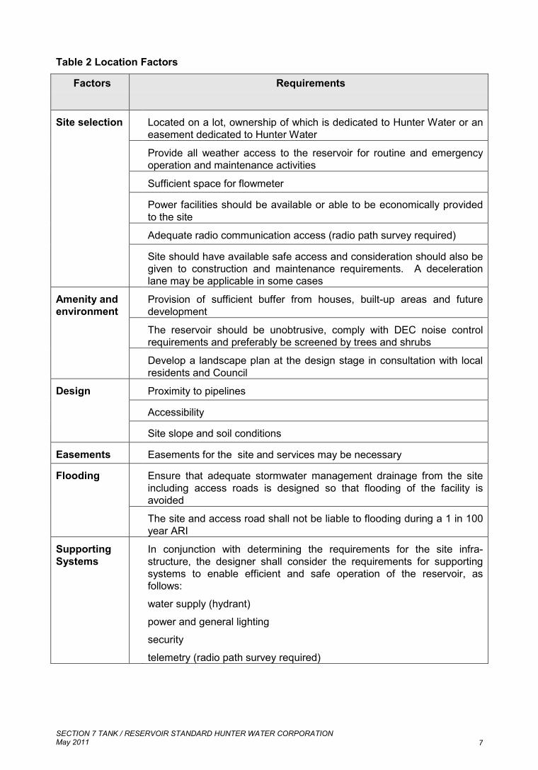
Table 2 Location Factors
Factors Requirements
Located on a lot, ownership of which is dedicated to Hunter Water or aneasement dedicated to Hunter Water
Provide all weather access to the reservoir for routine and emergencyoperation and maintenance activities
Sufficient space for flowmeter
Power facilities should be available or able to be economically providedto the site
Adequate radio communication access (radio path survey required)
Site selection
Site should have available safe access and consideration should also begiven to construction and maintenance requirements. A decelerationlane may be applicable in some cases
Provision of sufficient buffer from houses, built-up areas and futuredevelopment
The reservoir should be unobtrusive, comply with DEC noise controlrequirements and preferably be screened by trees and shrubs
Amenity andenvironment
Develop a landscape plan at the design stage in consultation with localresidents and Council
Proximity to pipelines
Accessibility
Design
Site slope and soil conditions
Easements Easements for the site and services may be necessary
Ensure that adequate stormwater management drainage from the siteincluding access roads is designed so that flooding of the facility isavoided
Flooding
The site and access road shall not be liable to flooding during a 1 in 100year ARI
SupportingSystems
In conjunction with determining the requirements for the site infra-structure, the designer shall consider the requirements for supportingsystems to enable efficient and safe operation of the reservoir, asfollows:
water supply (hydrant)
power and general lighting
security
telemetry (radio path survey required)
SECTION 7 TANK / RESERVOIR STANDARD HUNTER WATER CORPORATIONMay 2011 8
7.6 EASEMENTSAs part of the planning phase, obtain all property easements for the access road, pipework,services, stormwater drainage and power supply. Site layout shall be arranged to minimisethe number of easements. If possible, underground power supply shall not cross otherservices.
7.7 SITE SURVEYThe whole of the reservoir site is to be surveyed by a registered surveyor to identify theboundaries, surface contours and existing services.
This information is to be used by the designer in siting the reservoir, considering theoperating levels for the reservoir, pipework routes (inlet / outlet, scour, overflow, bypass),flowmeter, water service, power supply and drainage as well as the access roadway andturning areas.
The site survey shall also indicate the proximity of adjoining properties, particularly thosewhich may be impacted upon adversely by the construction and operation of the reservoir.
During the testing phase, accurate survey is to be undertaken and compared to baselinesurvey prior to filling.
7.8 GEOTECHNICALA geotechnical investigation is required to determine ground conditions which will imposerequirements on the designer. The designer shall address: Reservoir foundations; Pipework thrust restraint; Access road and hardstand area; Mine Subsidence / Settlement issues
The geotechnical consultant is to prepare both a factual and interpretive report which detailsthe investigation and findings.
7.9 ROAD ACCESSAll weather access is to be provided from the closest public road to the reservoir site. Whereaccess from a public road is not available then a suitable access easement shall be createdin favour of Hunter Water. The design of the access road shall reflect the size and operatingrequirements of Hunter Water maintenance vehicles.
The road shall be an all weather sealed road and have a suitable turning area for a 5 tonnemaintenance truck or as required for a larger vehicle if nominated by Hunter Water. Theminimum road width shall be as stated below with local widening as required at bends.Allowance for the parking of two 5t trucks shall be provided adjacent to the reservoir.
Minimum access road requirements Minimum pavement width3 metres Provide access road around full extent of reservoir Desirable maximum grade – 12.5% Absolute maximum grade – 15% (>15% may be acceptable where concrete pavements
are used) Preferred crossfall – 3% Maximum crossfall – 5%

SECTION 7 TANK / RESERVOIR STANDARD HUNTER WATER CORPORATIONMay 2011 9
The access road shall be designed in one of the following materials: Flexible pavement with asphalt seal Concrete pavement
7.10 HYDRAULIC DESIGN
7.10.1 INLET PIPEWORK
The inlet pipe diameter should be sized for peak instantaneous (all pumps running, nodemand) flows and should be one pipe size larger than in the incoming watermain to allowfor a future increase in capacity.
A bend / nozzle should be provided on the discharge to promote mixing.
Inlet pipework is to typically be DICL however for steel reservoirs the connection through thefloor is to be mild steel welded to the floor plates.
7.10.2 AUTOMATIC INLET VALVES (AIV)Suitable AIV arrangement will be by electrically actuated valve only, located local to the tank.No AIV is required for direct pumped systems.
The Corporation is to advise where use of fail safe condition of electric actuator is required.
7.10.3 OUTLET PIPEWORK
The outlet pipe diameter should be sized for peak instantaneous (no pumps running, peakdemand) flows and should be one pipe size larger than in the discharge watermain to allowfor a future increase in capacity.
The outlet should nominally be located close to the centre of the reservoir. The outlet pipe isto be positioned at a height to minimise the risk of any accumulated sediment within thereservoir being disturbed and being discharged during reservoir operation. This is typicallyachieved by positioning the outlet above the designed grade of the reservoir floor, normallygraded to achieve a minimum 100mm fall.
Outlet pipework is to typically be DICL however for steel reservoirs the connection throughthe floor is to be mild steel welded to the floor plates.
7.10.4 OVERFLOWA vertical pipe located outside the reservoir (where possible) with a suitable inletarrangement set at an appropriate invert level would form the outlet structure.
The overflow pipe diameter should be sized for peak instantaneous (all pumps running, nodemand) flows and sized to prevent excessive velocities. The overflow pipe is normally onesize large than the inlet pipeline.
Provide a bellmouth on the overflow, situated a minimum 200mm above TWL with minimumof 300mm freeboard between top of bellmouth and underside of roof members. Ensure thatthe bellmouth is free of obstruction from roof members.
Undertake a risk based assessment of time for overflow due to response times, telemetrybackup, asset criticality and location. Consideration is also to be given to instrumentationtime delays, accuracy and sensor calibration when selecting operating levels.
To ensure the overflow is always operational there not to be valves on the overflow line.
SECTION 7 TANK / RESERVOIR STANDARD HUNTER WATER CORPORATIONMay 2011 10
Overflow pipework is typically DICL. For fabricated steel reservoirs the connection throughthe wall plates shall be mild steel welded and the overflow pipework components are to beprotected using the internal solventless epoxy coating system.
Attachments and fixings for all internal components of the overflow pipework are to be grade316 stainless steel.
The overflow line shall discharge to an energy dissipation pit or other approved location.
Provide a visual overflow level marker at the roof entry hatch.
7.10.5 SCOUR / WASHOUT BULKHEAD
A washout bulkhead is to be installed in the wall strake of fabricated mild steel reservoirsadjacent to the overflow pipe as per attached drawing RES-108. The scour point in concretetanks is to be located as to optimise scour and cleaning activities.
A suitably sized scour pipe would extend from the external side of the bulkhead or scourpoint to an energy dissipation pit or other approved location.
The scour pipeline is to be as a minimum, the same diameter as the inlet pipe and willgenerally connect through a valved connection to the overflow line.
An external pit shall be provided in the scour line to allow sludge to be trapped and pumpedout.
7.10.6 WASHDOWN HYDRANTA spring hydrant connection for manual washdown is to be located in the access road closeto the main personnel access hatch. The supply for this hydrant shall be a DN100 pipelineconnected to the upstream side of the inlet pipeline valve.
This hydrant will be used for manual washdown.
Allow for installation of the hydrant internally on concrete tanks and externally for mild steelfabricated tanks. Allow for valved connection of a booster for clean out.
7.10.7 SITE DISCHARGE STRUCTURE
An energy dissipation pit is required to reduce the energy of the overflow/scour dischargesdue to the driving head of the reservoir water level.
Other discharge locations may be acceptable subject to approval by HWC, such as localstormwater reticulation, stormwater channel, sewer manhole etc.
Assess the impacts to both upstream and downstream receiving water including flooding andcontamination due to both controlled and uncontrolled discharges for the chosen option.
Ensure retention of sediment and sludge within a pit.
7.11 WATER QUALITY ASPECTS
7.11.1 MIXING OF STORAGEStagnant areas within the reservoir can lead to microbiological growths, which may bedifficult to control. Based on the size of the proposed storage (<10ML), mechanical mixing isnot normally required where provision of separate inlet and outlet pipework / nozzles areused. The arrangement for a circular reservoir will be a tangential inlet and a central outletarranged so that the inlet and exit energy maintains rotation of the water in the reservoir (i.e.

SECTION 7 TANK / RESERVOIR STANDARD HUNTER WATER CORPORATIONMay 2011 11
a dynamic volume is created). Direct inlet nozzle to maximise mixing of the reservoir.Normally the acceptable criteria for reservoir turnover would be at least once per day.
For large reservoirs (>10ML), CFD (Computational Fluid Dynamics) analysis is required todetermine whether adequate mixing / contact time can be achieved without use of asubmersible mechanical mixer.
7.11.2 VENTILATION / VERMIN PROOFING DETAILSThe Australian Drinking Water Guidelines (ADWG) stress the importance of securing thedistribution system and it is recommended that the following measures should beincorporated into the design.
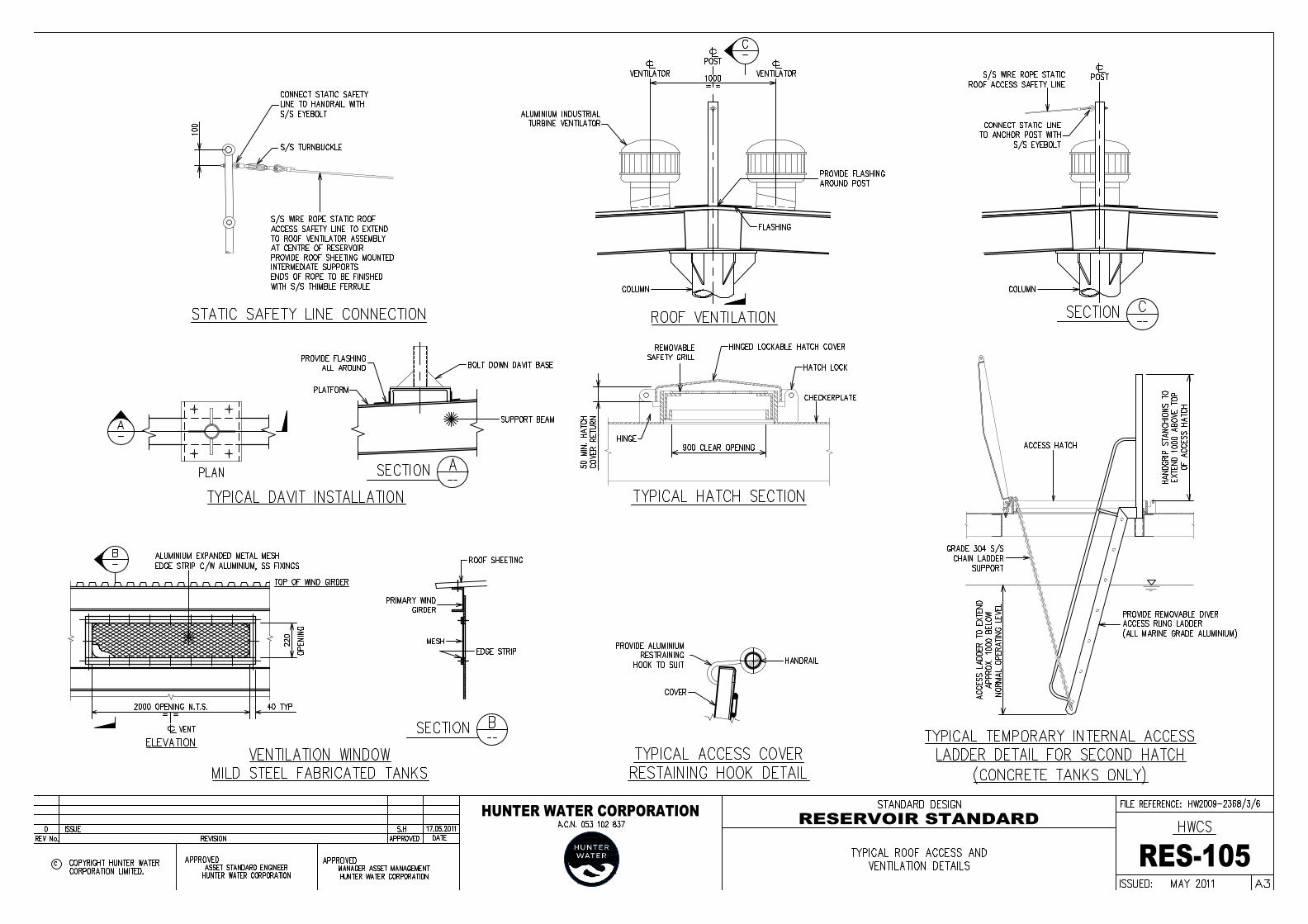
While no ventilation is the ideal for water quality, it is desirable / good design practice toprovide sufficient natural some ventilation to limit corrosion of the roof structure and assist inminimising OHS risks during confined space entry. This can be achieved by a combination ofinlet ventilation openings provided at the top of the wall strake together with ventilatorslocated at the centre of the roof structure.
Ventilators shall be designed to allow for air to be discharged during reservoir filling and for 6air changes per hour based on the air volume above TWL. Normally turbine ventilators areinstalled (refer drawing RES-105), consideration should be given to use of fixed ventilators inhigh wind areas.
To guard against the entry of contaminants, for example birds and small animals, allventilation openings will be covered with a vermin proof mesh consisting of corrosionresistant materials (marine grade aluminium or stainless steel).
Provide a ventilation access hatch in bottom wall strake to enable forced ventilation for futuremaintenance / coating application.
7.11.3 INLET NOZZLESNormally separate inlet / outlet pipework to the reservoir is required. Where the Corporationaccepts a common inlet / outlet pipework arrangement, provide a Hydraulic EnhancementNozzle (HEN) complete with dual flap gate on the inlet pipework to assist with mixing.
The HEN is normally constructed of HDPE and is to incorporate grade 316 stainless steeldiver safety bars.
7.11.4 RE-CHLORINATIONDetermine in conjunction with the Corporation whether a site specific chlorination facility isrequired to boost disinfection levels within the system.
Where required ensure that adequate land area is available for operation and maintenanceof the facility.
7.11.5 STORMWATER MANAGEMENT DETAILSDesign the roof structure to allow the rainwater to flow off the roof to the hardstand areabelow around the reservoir and be managed using a network of site drainage pits and pipes.
Detail site drainage so that it provides adequate protection to the access road, reservoir andsurrounds and also complies with local Council or other authorities requirements.
Ensure all roof water drains off the reservoir, full length sheeting is to be used wherepractical and laps of roof sheeting to be in accordance with the manufacturer’srecommendations. Gutters should not be used as the accumulation of leaves can permit

SECTION 7 TANK / RESERVOIR STANDARD HUNTER WATER CORPORATIONMay 2011 12
entry of contaminants into the reservoir. Ensure hatches are designed to prevent the ingressof water run-off.
7.12 BOUNDARY FENCINGReservoir site boundaries are typically unfenced. Where a site boundary fence is required,provide a lockable 4m wide access gate and an additional personnel access gate. Other sitesecurity may be required for some locations and Hunter Water is to be consulted as to theirrequirements for each site.
Incorporate the HWC standard boundary fencing requirements in the design where required(refer drawing RES-113).
7.13 LANDSCAPINGEnsure that the aesthetics of the area are maintained and prepare a landscape plan thataddresses this issue as part of the design drawings and specification. The landscape planshall be designed to blend into the local area and be determined on lowest cost for ongoingmaintenance.
Choices of flora shall be suitable to the area. Trees and shrubs are to be Australian natives.If the reservoir is within a public reserve or crown land then the local Council shall beconsulted to identify appropriate types of planting and any other specified requirements.
No planting over services or under powerlines is allowed and special attention shall be paidto the type of trees and shrubs planted in the vicinity of pipework. Consideration shall alsobe given to the location of plants.
Hunter Water guidelines for planting can be found in Hunter Water Corporation’s website:
http://www.hunterwater.com.au/docs/reports/TreeRoots.pdf
7.14 DESIGN LIFEDesign service life requirements are shown in the following table:
Table 3 Asset Design Life
Component Minimum Service Lifeassuming maintenance is
carried out
Steel Reservoir 75 years
Concrete Reservoir 75 years
Rafters and Columns 40 years
Purlins 25 years
Roof Sheeting 25 years
Pipework 50 years
Mechanical Equipment 25 years
Electrical Equipment 15 years
Cathodic Protection System 20 years

SECTION 7 TANK / RESERVOIR STANDARD HUNTER WATER CORPORATIONMay 2011 13
7.15 WHOLE OF LIFE COSTSWhere requirements nominated in this document allow a choice in the type of reservoir type,arrangement or materials of construction, the final choice will normally be determined by themost cost-effective method. Cost effectiveness should be determined by a net present valueanalysis.
Factors to be considered are: Cost of reservoir structure. Access and maintenance costs. Life and replacement cost of coatings, roof and including ancillary items such as
switchgear, telemetry, ventilation equipment etc. Discounted energy cost over the life of the reservoir (Only where mixers are required). Net present values (NPV’s) of alternatives.
7.16 DURABILITYAdopt the following material selection criteria to ensure long term integrity, to minimise /eliminate material degradation and the need for ongoing maintenance.
Table 4 Coastal Tank Material Requirements (<5km from coast)
Element Steel Reservoir Concrete Reservoir
Walls 250MPa Mild Steel Plate Concrete 40MPa (min)
Floor 250MPa Mild Steel Plate Concrete 40MPa (min)
Rafters Galvanised Mild Steel Galvanised Mild Steel or ExtrudedMarine Grade Aluminium Alloy (Zbeams)
Purlins Seasoned Hardwood Timberor Roll Formed Marine GradeAluminium (C-Profile)
Seasoned Hardwood Timber orRoll Formed Marine GradeAluminium (C-Profile)
Roof Sheeting Aluminium
Alloy 5251 (Min 0.9mm)
Aluminium
Alloy 5251 (Min 0.9mm)
Roof Access Platform Marine Grade Aluminium Marine Grade Aluminium
Roof Access Covers Marine Grade Aluminium Marine Grade Aluminium
Internal Ladder N/A 316 Stainless Steel / FRP / GRP
External Stairs Marine Grade Aluminium Marine Grade Aluminium
Columns Mild Steel CHS 316 Stainless Steel or ReinforcedConcrete
Handrails Marine Grade Aluminium Marine Grade Aluminium
Pipework DICL / MSCL DICL / MSCL
SECTION 7 TANK / RESERVOIR STANDARD HUNTER WATER CORPORATIONMay 2011 14
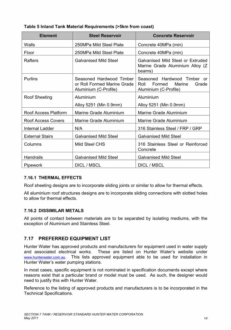
Table 5 Inland Tank Material Requirements (>5km from coast)
Element Steel Reservoir Concrete Reservoir
Walls 250MPa Mild Steel Plate Concrete 40MPa (min)
Floor 250MPa Mild Steel Plate Concrete 40MPa (min)
Rafters Galvanised Mild Steel Galvanised Mild Steel or ExtrudedMarine Grade Aluminium Alloy (Zbeams)
Purlins Seasoned Hardwood Timberor Roll Formed Marine GradeAluminium (C-Profile)
Seasoned Hardwood Timber orRoll Formed Marine GradeAluminium (C-Profile)
Roof Sheeting Aluminium
Alloy 5251 (Min 0.9mm)
Aluminium
Alloy 5251 (Min 0.9mm)
Roof Access Platform Marine Grade Aluminium Marine Grade Aluminium
Roof Access Covers Marine Grade Aluminium Marine Grade Aluminium
Internal Ladder N/A 316 Stainless Steel / FRP / GRP
External Stairs Galvanised Mild Steel Galvanised Mild Steel
Columns Mild Steel CHS 316 Stainless Steel or ReinforcedConcrete
Handrails Galvanised Mild Steel Galvanised Mild Steel
Pipework DICL / MSCL DICL / MSCL
7.16.1 THERMAL EFFECTSRoof sheeting designs are to incorporate sliding joints or similar to allow for thermal effects.
All aluminium roof structures designs are to incorporate sliding connections with slotted holesto allow for thermal effects.
7.16.2 DISSIMILAR METALS
All points of contact between materials are to be separated by isolating mediums, with theexception of Aluminium and Stainless Steel.
7.17 PREFERRED EQUIPMENT LISTHunter Water has approved products and manufacturers for equipment used in water supplyand associated electrical works. These are listed on Hunter Water’s website underwww.hunterwater.com.au. This lists approved equipment able to be used for installation inHunter Water’s water pumping stations.
In most cases, specific equipment is not nominated in specification documents except wherereasons exist that a particular brand or model must be used. As such, the designer wouldneed to justify this with Hunter Water.
Reference to the listing of approved products and manufacturers is to be incorporated in theTechnical Specifications.

SECTION 7 TANK / RESERVOIR STANDARD HUNTER WATER CORPORATIONMay 2011 15
7.18 STRUCTURAL DESIGN
7.18.1 FABRICATED MILD STEELDesign the reservoir to meet the following: AWWA D100-05 Section 14 using API 650 variable point design method; Roof and associated columns and supports to AS4100; Wind load to AS1170.2; Earthquake load design to AS1170.4 and NZS 3106; AS1170.0-2002 Structure design actions; AS1170.1-2002 Structure design actions Part 1 Permanent, imposed & other actions; AS 1657-1992 Fixed platform, walkway and ladder loads AS 5100.5 Non- water retaining concrete elements Mild steel plate for reservoir shell and floor to AS 3678 (Grade 250 only) Mild steel sections for roof structure, supports, and platforms to AS3679 (Grade 300) Mild Steel columns to AS1163 (Grade 350)
In addition, the following parameters shall be incorporated into the wall and floor platedesign: Corrosion allowance of 2mm for all plate Design limiting stress for base bending up to 0.5 x Yield Stress is considered acceptable. The maximum additional horizontal deflection due to filling shall be the lesser of
height/250 and 20mm. Careful handling methodologies / procedures are to be developed and employed on-site
to minimise plate buckling / deformation.
The Design Report should include as a minimum the method of calculation of the steel shell,hoop stress in the walls, bending stress in the floor to wall joint and wall deflections.
7.18.2 REINFORCED CONCRETE TANKS (CAST IN-SITU & PRE-CAST)Design the reservoir to meet the following: AS3735 Concrete Structures for Retaining Liquids; AS3600 Concrete Structures; Other relevant standards include AS1012.3, AS1012.4.1, AS1012.4.2, AS1012.4.3,
AS1012.3 , AS1141.5, AS1141.6.1, AS1141.6.2, AS1302, AS1303, AS1304, AS1478,AS3582, AS3972, AS1379, , AS2758.1 and AS3610;
Roof and associated columns and supports to AS4100; Wind load to AS1170.2; Earthquake load design to AS1170.4 and NZS 3106; AS1170.0-2002 Structure design actions; AS1170.1-2002 Structure design actions Part 1 Permanent, imposed & other actions; AS 1657-1992 Fixed platform, walkway and ladder loads; and AS 5100.5 Non- water retaining concrete elements.
In addition, the following parameters / considerations shall be incorporated into the design: Minimum steel for crack control Concrete mix design Minimise shrinkage effect by pouring the sections of the work between construction joints
in a sequence such that there will be suitable time delays between adjacent pours. Curing methodology

SECTION 7 TANK / RESERVOIR STANDARD HUNTER WATER CORPORATIONMay 2011 16
Single reinforced concrete structural elements are not permitted. Minimum wall thicknessof double reinforced structural elements to be 230mm wide.
Concrete pour heights for vertical elements to be minimised to prevent segregation Jointing and sealing methodology
7.18.2.1 Cast In-Situ
Where approved by the Corporation, use of reinforced cast in-situ concrete constructionmethod is acceptable where whole of life costs are considered.
Additional site surveillance is normally required to ensure quality is maintained in terms ofslump, cover to reinforcement, stability of formwork, testing regime, water seals, placement,monitoring use of admixtures and water cement ratio etc.
7.18.2.2 Pre-Cast Post TensionedWhere approved by the Corporation, use of pre-cast concrete post tensioned constructionmethods is acceptable where whole of life costs are considered.
Additional detail design and construction requirements are normally required to ensurequality is maintained in terms of precast panel design, joint interfaces, tensioning, stitchpanel, etc.
7.18.2.3 Concrete Mix Design RequirementsUse Type SR to AS 3972 and containing 25% fly ash (as cement substitute) to AS 3582 Part1 (fine grade only). Silica Fume may also be used in lieu of fly ash.
Table 6 Concrete Mix Requirements
S40 N25RequirementType 1 Type 2
Cement Type SR GP
Minimum cement kg/m3 380 -
Maximum cement kg/m3 410 -
Fly ash (or silica fume) used as cementsubstitute
25% -
Maximum W/C Ratio 0.45 -
Project specific laboratory trial mix requiredfrom plant where concrete for the structure is tobe supplied from Yes / No
Yes No
Materials and Mix
Supply grading curve for mix design
Yes / No
Yes No
CharacteristicStrength (MPa)
Compressive f'C 28 days 40 25
Nominal slump (mm) 80 -Other
Drying shrinkage (3 weeks) 500 x 10-6 -

SECTION 7 TANK / RESERVOIR STANDARD HUNTER WATER CORPORATIONMay 2011 17
Drying shrinkage (Max. @ 59 days) 700 x 10-6
Total alkali reactive content (Not greater than) 3.0kb Na2O /m3
Air content % - -
Surface finish See Clause ‘ConcreteFinishes’
Pumped concrete accepted Yes/No Yes Yes
Minimum period between adjacent pours (days) 3 -
Type 1: All liquid retaining structures, including any lining used as watertightness barrier.
Type 2: Footpaths, thrust blocks, concrete encasement, plug concrete, blinding concrete andconcrete kerbs.
7.18.2.4 Aggregates
Aggregates used in the manufacture of concrete shall be of clean hard, chemically inert anddurable particles that comply with AS2758.1 for an exposure classification ‘C’ and compriseeither normal weight or heavy weight aggregates.
The water absorption of aggregates shall not be less than 3% when tested in accordancewith AS1141.5, AS1141.6.1, AS1141.6.2.
The alkali reactivity of the aggregate shall be assessed to clause 10 of AS2758.1.
7.18.2.5 Addition Of WaterWater used in the manufacture of concrete shall be of good quality complying with AS1379.
7.18.2.6 Chemical AdmixturesAdmixtures that enhance the workability, reduce water cement ration, control slump,minimise shrinkage and control the setting time of the concrete may be included in the mix ina controlled manner, provided they have been proven to not impair the performance of theconcrete.
Air entraining admixtures may be used provided that the air content, determined inaccordance with AS1012.4.1, AS1012.4.2 or AS1012.4.3 does not exceed 4%.
Admixtures shall comply with AS1478.
7.18.2.7 Cover Requirements
Provide the following minimum concrete cover to reinforcement:
Table 7 Minimum Concrete Cover
Location Concrete Cover
Air face 50
Water face: 65
Ground face:
(a)Against a polyethylene membrane or blinding concrete 50
(b)Directly in contact with the ground 65
SECTION 7 TANK / RESERVOIR STANDARD HUNTER WATER CORPORATIONMay 2011 18
7.18.2.8 Joint SealingProvide PVC waterstops for all cast in-situ joint interfaces. Hydrophilic, mastic type,waterstops shall not be used.
Interfaces between pre-cast sections or between pre-cast and cast in-situ to be detailed onthe design drawings. Refer to drawing RES-115 for floor to wall joint standard arrangement.
Where joint sealing is to include a primary and secondary seal, watertightness test is to becompleted and passed prior installation of secondary seal.
7.18.2.9 Concrete RepairsRepair all air voids, bolt holes and honeycombing using a suitable epoxy mortar appliedstrictly in accordance with manufacturer's instructions.
Repairs by bagging using cement mortar etc will not be permitted. Submit a work methodstatement to the PAP for approval 48 hours prior to undertaking repairs.
Other repair methodologies may be acceptable, subject to approval such as injectionmethods.
7.18.2.10 Watertightness Test
Filling methodology of liquid-retaining structures with first water is not to exceed a uniformrate, generally not greater than 2 m in 24 h to the top of the structure to test forwatertightness.
When first filled, the liquid level is to be maintained by the addition of further liquid for astabilizing period of 7 days while absorption and autogenic healing takes place. After thestabilizing period, the level of the liquid surface shall be recorded at 24 h intervals, for a testperiod of 7 days. During this 7-day test period, the total permissible drop in level, afterallowing for evaporation and rainfall (if the test is made for an uncovered structure) shall notexceed 1/500th of the average water depth of the full tank or 10 mm, whichever is less.
Determine evaporation during testing period by direct measurement of evaporation losses ina manner approved by the National Association of Testing Authorities.
7.18.3 BOLTED STEEL TANKSBolted steel tanks are not acceptable except for shorter design life applications such as 15years.
7.19 ROOF ACCESS
7.19.1 ROOF ACCESS STAIRSRoof access shall be provided for all reservoir types. This shall be done via a free standingfabricated stairs / platform structure in lieu of caged ladder system to reduce OHS risks tooperations and maintenance personnel.
Provide a security enclosure around perimeter of stair access (refer drawing RES-114).Ensure that electrical switchboard is located within the security fenced area.
Vertical ladders are not acceptable to the Corporation.
SECTION 7 TANK / RESERVOIR STANDARD HUNTER WATER CORPORATIONMay 2011 19
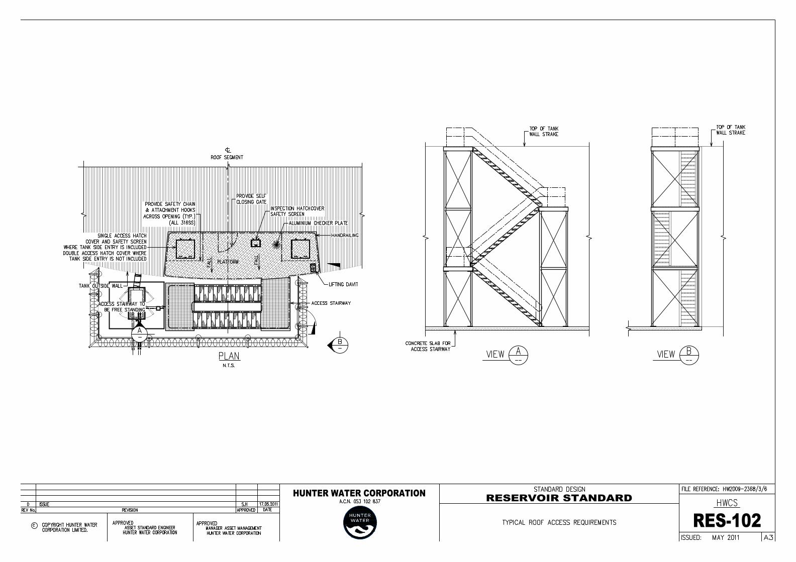
7.19.2 ROOF PLATFORMFor concrete tanks, the reservoir roof platform (at top of the roof for access into the reservoir)shall be located directly over the traffic accessible area in order to enable the maintenanceoperator to use the davit to pick up equipment from a vehicle below (refer drawing RES-109for davit details)
The roof platform is to be constructed of marine grade aluminium.
For concrete tanks, the roof platform shall be large enough to provide for the hatch cover andlifting davit. There shall be sufficient room on the platform when the cover is open foradequate access to the cover and ladder with a minimum unobstructed flat area of 1,500 mmx 3,000 mm,
The roof platform is to have a handrail on its perimeter.
A gate shall be provided in the handrail to give access to the peak of the roof. The gate willbe used for a person to access the roof, walking in a straight line to the peak, where alanyard attachment will be located for the person to latch on to – all the while the person isprotected from falling off the roof by the handrails around the roof platform. (Refer drawingRES-102 and -05).
7.19.3 MAINTENANCE ACCESS VEHICLE HATCH
For tanks greater than 30m diameter provide a vehicle hatch minimum dimension 4000mm x2000mm to be installed on the roof to allow a bobcat or similar to be lowered into the tank.
Hatch cover to be hinged operated and lockable when cover is at an open or closed position.Provide mechanical means of opening, hand operated winch or similar.
7.19.4 ROOF ACCESS HATCH
Provide a lockable hatch cover over the internal ladder (no internal ladder is required for asteel reservoir but the hatch cover position shall be similar to a concrete reservoir).
Hatch cover to be hinged operated and lockable when cover is at an open or closed position.Provide mechanical means of opening, hand operated winch or similar, for heavy hatchescovers or hatches covers positioned with restricted access.
For concrete tanks provide two means of entering the structure by access hatches.
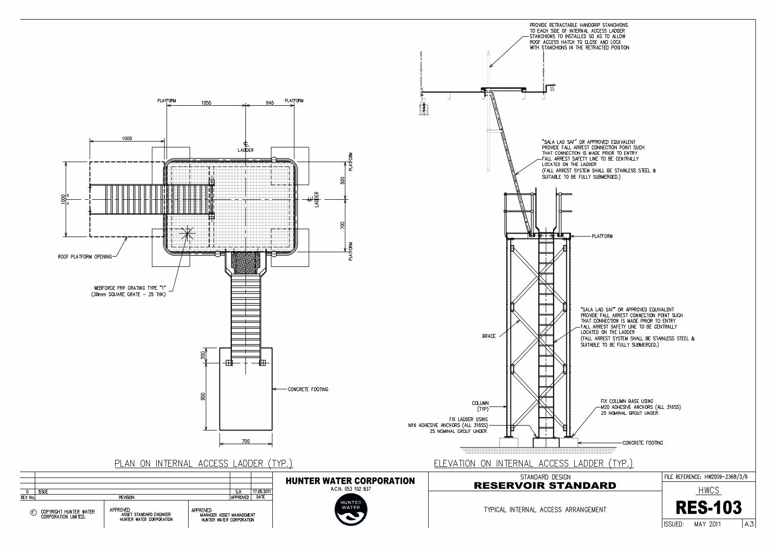
7.19.5 INTERNAL LADDERProvide an internal ladder (for a concrete reservoir only) extending from the Roof Platform tofloor level. Material for the internal ladder shall be either stainless steel Grade 316, FRP orGRP. The ladder shall have either extended handrails or similar system to orientateperson(s) descending or ascending.
Provide a suitable fall arrestor system where the potential fall from height exceeds legislatedlimits or risk assessment justifies provision of such a system. Design the attachment point forthe Lanyard (Life Line) in such a way to allow a person to be attached before entering thehatch area. The ladders and fall arrest systems must be compliant with AS1657 FixedPlatforms, Walkways, Stairways and Ladders and AS/NZS1891 Industrial Fall ArrestSystems and be clearly marked with the safe working load.
Refer drawing RES-103.
SECTION 7 TANK / RESERVOIR STANDARD HUNTER WATER CORPORATIONMay 2011 20
7.19.6 EYEBOLTSWhere required, all load bearing components / attachments to be load tested as per AS1891.
Eyebolts are to be properly secured on a central post to enable maintenance personnel toattach Lanyards (Life Lines) and to work around the reservoir roof and wall (refer drawingRES-102 and -05).
Provide two (2) eyebolts for each opening in the roof. Locate eyebolts approximately 1,600mm from the centre of the opening to suit 1,800 mm long lanyards / life lines and to securethe harness worn by the stand-by personnel.
Provide a minimum 35mm hole for eyebolts to enable attachment of lanyards / life lines.
7.19.7 DAVIT AND LIFTING GEARThe davit and lifting gear is to be made from galvanised steel (refer drawing RES-109).
Provide for a manually operated winch (for a concrete reservoir only) that can be attached tothe davit arm. The davit and lifting gear shall be hand operated and designed to comply withthe following minimum requirements: The centre of the lifting gear shall be above the centre of the opening for the hatch cover, Ground unloading point shall be at least 600 mm away from objects (i.e. handrails, posts,
roof and wall), The davit shall be capable of unloading a person on the Roof Platform (i.e. within the
handrails, not on the roof), Lifting gear shall be sufficient to pick up load from the floor of the reservoir and unload on
the ground outside the reservoir, There shall be a minimum 2.4m clearance above the roof or platform level to the jib, The davit shall have an eyebolt or similar device to enable easy detachment of the lifting
gear, The davit shall have a handle or other device to facilitate slewing by hand, The davit shall have a maximum horizontal force to comply with the standard /
regulations, The davit shall have a minimum safe working load capacity of 1.5 Tonne, The davit shall have a maximum deflection (vertical) 10mm.
The ground landing area shall be an unobstructed flat horizontal area of minimum horizontaldimensions 6000 mm x 2000 mm and shall be so positioned in relation to the reservoir wall inorder to enable unloading at the approximate centre of the area.
7.20 WALL STRAKE ACCESS (FABRICATED STEEL ONLY)
7.20.1 PERSONNEL ACCESS HATCHES
For steel reservoirs a minimum of two wall strake personnel hatches are to be included,located opposite one another. Personnel hatches are to be 1100mm wide by 1800mm high,to allow both personnel access and access for a small excavator “Dingo” or equivalent.(Refer drawing RES-106)
7.20.2 VENTILATION HATCHFor steel reservoirs a 600mm diameter ventilation hatch shall be provided to provide allowforced ventilation to be provided. This is primarily required when painting the internalsurfaces. (Refer drawing RES-107)
SECTION 7 TANK / RESERVOIR STANDARD HUNTER WATER CORPORATIONMay 2011 21
This ventilation hatch ensures that trip hazards are removed from main personnel accesshatch areas.
7.21 STEEL FLOOR PLATESThe floor shall be graded from the centre to the outside of the reservoir at a grade of 1% (i.e.for tanks < 10ML).
Annular plates are to be used for wall / floor connection stresses.
For annular plates and floor plates which are to be in contact with the ground, apply75micons DFT of inorganic zinc up to a minimum of 1000mm from the reservoir perimeter.
7.22 COLUMNSThe number of internal columns should be kept to a minimum. Where possible the roofstructure should be designed with only a central column.
Align plates to ensure columns are located in areas free of joints.
For steel reservoirs roof support columns shall be painted with the same internal coatingsystem as the walls and floor.
For concrete reservoirs roof support columns shall be 316 stainless steel bolted to theconcrete floor slab or be constructed of reinforced concrete.
7.23 SAMPLING ARRANGEMENTIncorporate sampling point arrangement as shown on drawing RES-110
7.24 RESERVOIR TESTING
7.24.1 GENERALThe reservoir shall be tested in accordance with an approved detailed testing procedure.This procedure shall be submitted to HWC for approval prior to testing. The details of thetesting procedure shall be based upon the following considerations: Ensure that testing water can be removed quickly and safely from the reservoir if
required. Ensure that foundation settlement behaviour is within predicted limits. Ensure there is no leakage and that the reservoir is fit for service.
The following requirements shall be incorporated into the detailed testing procedures asappropriate.
7.24.2 MILD STEEL FABRICATED TANKS
7.24.2.1 Floor TestingThe floor of the reservoir shall be tested for leaks either by: Vacuum testing using a vacuum box and a pressure of 650 mbar absolute (i.e. 350 mbar
of vacuum). 100% magnetic particle examination to AS1554.1, with no cracking or porosity permitted.

SECTION 7 TANK / RESERVOIR STANDARD HUNTER WATER CORPORATIONMay 2011 22
7.24.2.2 Wall TestingThe reservoir shall be tested by filling with water to the normal operating top water level.
The rate of filling shall be controlled and managed to minimise loading to the tank.
The full exterior of the reservoir, including all mountings shall be continuously inspectedduring the water testing, for the presence of leakage. If leakage is detected, filling shall ceaseimmediately and an approved method of repair shall be completed prior to recommencementof the testing. The water level shall be lowered to an approved "safe" level prior to carryingout any repair work. This "safe" level shall be at least 600 mm below the area of repair.
The level of the top water surface shall be monitored for the holding period of 48 hours. If thewater level fails during this period, then the water level shall be held for a further 48 hours. Ifa further drop in water level is detected, an approved procedure for leakage detection andrepair shall be immediately instigated.
7.24.3 FOUNDATIONSThe load / settlement behaviour of the foundations shall be carefully monitored during thewater testing phase by accurate survey compared to baseline survey prior to filling.
If the total settlement at any control point exceeds 10 mm or the differential settlementbetween any two adjacent control points on the perimeter exceeds 5 mm, then filling shall beimmediately terminated and the testing procedure shall be modified or abandoned.
All survey work associated with testing shall be carried out by an independent registeredsurveyor, with a report summary of results presented to HWC on completion.
7.24.4 HYDROSTATIC TESTINGPrior to testing, the tank shall be thoroughly cleaned.
At the completion of testing, the test water shall be returned to supply or allowed to drain tothe scour line.
The Corporation shall approve the intended method of water disposal prior to emptying thetank or putting it into service. The Corporation will be responsible for addition of chlorinetablets or similar to ensure effective chlorination of the tank prior to putting into service.
7.24.5 OVERFLOW / SCOUR
The operation at the overflow and scour systems shall be tested using a HWC approvedprocedure. Care shall be taken to ensure that no damage is caused to the reservoir or theenvironment.
7.25 COATING SYSTEMS FOR FABRICATED STEEL TANKS
7.25.1 GENERALProtection of fabricated carbon steel components is required for all reservoirs. All work iscarried out in a competent manner by personnel experienced in application of the paintingsystems.
All coatings are to be applied on-site with provision for full encapsulation.
SECTION 7 TANK / RESERVOIR STANDARD HUNTER WATER CORPORATIONMay 2011 23
7.25.2 SURFACE PREPARATION
7.25.2.1 Procedure
All surfaces to be protective coated using solvent-less high build epoxy shall be blast cleanedto give a Class 3 – “White Metal” standard of surface preparation in accordance withAS1627.4.
The maximum surface profile height shall not exceed one-third of the dry film thickness of thecoating system. The minimum profile height shall be as recommended by the coatingmanufacturer.
All surfaces to be protective coated shall be free from rust, mill scale, oil, grease, dust orother contaminants and shall be thoroughly dry and clean.
All irregularities on the surface, including weld spatter, welding slag etc shall be removed bygrinding flush prior to blasting.
Sharp edges shall be rounded (radius not less than 10 mm) before blasting.
Blast-cleaned surfaces shall be coated as soon as possible and shall be coated before anydiscoloration occurs. At no stage shall a blast-cleaned surface be permitted to standovernight without being coated. If flash corrosion does occur, the surfaces shall be re-blastedto the specified class of surface preparation.
7.25.2.2 Abrasive MaterialThe abrasive medium shall be: Silica-free. Clean and dry. Free from contaminants such as dirt, clay and organic matter. Free of chloride contamination. Free of soluble copper. Free of metallic copper.
The Contractor shall take all necessary precautions to ensure that blast grit is effectivelycontained and removed promptly from site. Implement additional site protection measures asdirected by the Superintendent, to ensure that site blasting operations do not adverselyimpact the surrounding environment and meet environmental requirements.
7.25.3 COATING MATERIALS
All coating material containers shall bear the manufacturer's label, batch number, instructionsfor application and date of expiry where applicable. Keep written records of batch numbersand provide to HWC.
7.25.3.1 Reservoir Internal SurfacesThe coating for all internal surfaces subject to submergence including, walls, floor, pipeworkand access door shall be two (2) coats of a high build solvent-less epoxy, each coatconsisting of a minimum DFT (Dry Film Thickness) of 250 microns. Each coat is to be adifferent colour, the finish coat colour shall be white. Each coat shall be applied to the wholereservoir in one continuous coating before starting the next coat.
If a holder primer is needed, the tank is to be completely washed out prior to application offinish coats.

SECTION 7 TANK / RESERVOIR STANDARD HUNTER WATER CORPORATIONMay 2011 24
7.25.3.2 External Surfaces (Coastal Tank <5km To The Coast)The coating for the reservoir external surfaces is to be a zinc epoxy to manufacturer’srequirements with a solvent borne acrylic as the topcoat also to manufacturer’s requirements.
External colour is normally ‘colorbond’ mist green, final selection to be confirmed by theCorporation.
7.25.3.3 External Surfaces (Inland Tank >5km To Coast)The coating for the reservoir external surfaces is to be two (2) coats of an inorganic zincsilicate to a minimum dry film thickness of 75microns per coat.
While preference is for the inorganic zinc finish, where site aesthetics are required, apply anadditional coating of solvent borne acrylic topcoat to manufactures requirements.
7.26 CATHODIC PROTECTION (CP) SYSTEM
7.26.1 GENERAL
Design of sacrificial anode CP systems is to be done by a specialist to ensure a corrosionprotection system which will provide protection of the fabricated steel reservoirs over anextended period (20+ years).
Normally reservoirs with submersible mixers require design of an impressed current system.
The CP system would normally comprise the following: Magnesium anode strings suspended from the roof using plastic inserts. Permanent copper/copper sulphate reference electrode strings also suspended from the
roof using plastic inserts. CP junction box containing a test panel (test point) external to the reservoir. The desired
position of the test panel on the roof of the reservoir. Conduit and cabling to run from the anode strings and electrode strings on the roof of the
reservoir to the test point and from the reservoir wall to the test point. Ensuring insulation and isolation of all reservoir internal components / equipment.
7.26.2 LOCATION OF FACILITIES
Anode roof holes are normally 80mm holes located one third of the distance from thereservoir wall to the centre, with each hole equidistant from each other around the reservoirroof.
Electrode roof holes normally 40mm diameters are to be located adjacent to the reservoirwalls. One should be located adjacent to the access hatch, and the other located on theopposite wall.
Locate a test point adjacent to the external ladder on an upstand or existing handrail.
7.26.3 ANODES
Provide for magnesium high potential anodes to AS 2239-1993, normally of dimensions50mm x 50mm x 1500mm, supplied with 6mm2 single core copper PVC insulated cable tails.The cable tails shall extend from the anodes to the roof junction box without cable joints.
Anode holes shall be fitted with stainless steel cathodic protection enclosures consisting of a250mm x 200mm x 150mm box with 1 off 100mm diameter hole drilled in side panelsplugged with 2 off 25mm conduit plugs supplied complete with 1 x 100mm PVC cap with a12mm hole drilled in end and complete with lockable handle.

SECTION 7 TANK / RESERVOIR STANDARD HUNTER WATER CORPORATIONMay 2011 25
The anode holes shall be fitted with UPVC inserts. Each UPVC insert shall be made asfollows: Use two sections of UPC; one of 70mm diameter and one of 180mm diameter, 10mm
thick. Fix the two sections together concentrically by gluing. Provide a stainless steel grade 316 support hook in the centre of the insert. A stainless
steel nut and washer on the top surface of the insert shall fix the support hook. Insert two cable glands in the insert. Ensure assembly is sealed to prevent ingress of rain water to the reservoir.
The anodes shall be suspended from the anode hole inverts. In each hole anodes shall belocated equidistant from each other with the lowest anode 0.5 metres from the floor. The topof the highest anode shall be approximately 5 metres from the floor. The anode tails shall befixed together with cable ties.
The anode tails shall be fixed to the support hooks, and the support arrangement shall be sodesigned as to provide support under robust water loading over a period of 20 years withoutdamage to the cable or slippage of the anodes.
The anode cables shall be run through the cable glands that shall be tightened appropriately.
On the top of each UPVC insert the four anodes shall be electrically bonded and connectedto a 6mm2 single core copper PVC insulated cable to the test point. The bonding shall bewith crimp links and housed within a UPVC junction box.
The crevice between the UPVC insert and the top surface of the roof shall be sealed with asilicone sealant.
7.26.4 ELECTRODESCopper/copper sulphate permanent reference electrodes suitable for permanent fresh waterimmersion are required. The electrodes tails shall extend from the electrodes to the roofjunction box without cable joints.
The electrode holes shall be fitted with UPVC inserts. Each UPVC insert shall be made asfollows: Use two sections of UPVC; one of 30mm diameter and one of 130mm diameter, 10mm
thick. Fix the two sections together concentrically by gluing. Provide a stainless steel grade 316 support hook in the centre of the insert. A stainless
steel nut and washer on the top surface of the insert shall fix the support hook. Insert two cable glands in the insert.
The electrodes shall be suspended from the electrode holes and the electrode tails shall befixed together with cable ties.
Alternative means of support will be considered but must be submitted for approval withsufficient written case history from previous applications.
Both electrode strings shall have the bottom electrode located with its bottom 0.5 metre fromthe floor and the other with its bottom 4 metres from the floor. A nylon rope shall be run withthe electrode cables and fixed to them with cable ties. A 1kg zinc weight of dimensions25mm x 25mm x 200mm shall be fixed to the bottom of the rope with its bottom 200mm fromthe floor.
The electrode tails, and support rope on one string, shall be fixed to the support hooks, andthe support arrangement shall be so designed as to provide support under robust waterloading over a period of 20 years without damage to the cable or slippage of the anodes.
The electrode cables shall be run through the cable glands tightened appropriately.
SECTION 7 TANK / RESERVOIR STANDARD HUNTER WATER CORPORATIONMay 2011 26
On the top of each UPVC insert a UPC junction box shall be installed. If any cableconnection is required in the cable run from the electrode to the test point, it shall be made inthe junction box.
The crevice between the UPVC insert and the top surface of the aluminium roof shall besealed with a silicone sealant.
7.26.5 TEST POINTThe test point shall comprise an aluminium or stainless steel grade 316 junction box locatedas per clause ‘Location of Facilities’. Alternative support arrangements may be consideredby the Corporation.
Within the junction shall be an insulated panel containing as a minimum; terminals for the sixanode strings, the reservoir connection and the four reference electrodes. Shunts shall beinstalled in each of the anode string connections. The anode string connections shallterminate on a copper bus to which the reservoir connection is also connected.
All cables shall be labelled with crimp on markers. All terminations and functions on the testpoint panel shall be provided with appropriate labelling, including the rating of the shunts.
7.26.6 CABLINGAll cabling on the roof shall be run in flexible conduit from the UPVC plastic insert junctionboxes to the roof junction box.
One UPVC conduit shall take all cabling from the roof junction box to the test point. Theconduit shall be fixed by a suitable method.
7.27 ELECTRICALThe electrical components of a reservoir installation comprise: Incoming power supply Switchboard containing metering, main distribution section, PLC and telemetry equipment Instruments for reservoir level etc. Area lighting and power Security system Lightning Protection System
7.27.1 POWER SUPPLYAll reservoir sites will be supplied from the local electrical distribution network. Generally asingle phase 230V 50Hz supply will be sufficient except for sites with three phase suppliedvalve actuators.
The Electricity Distributor needs to be consulted at the earliest possible stage in order tomake provision for such a connection.
A generator connection changeover switch facility is not required for typical reservoirswitchboards.
7.27.2 SWITCHBOARD
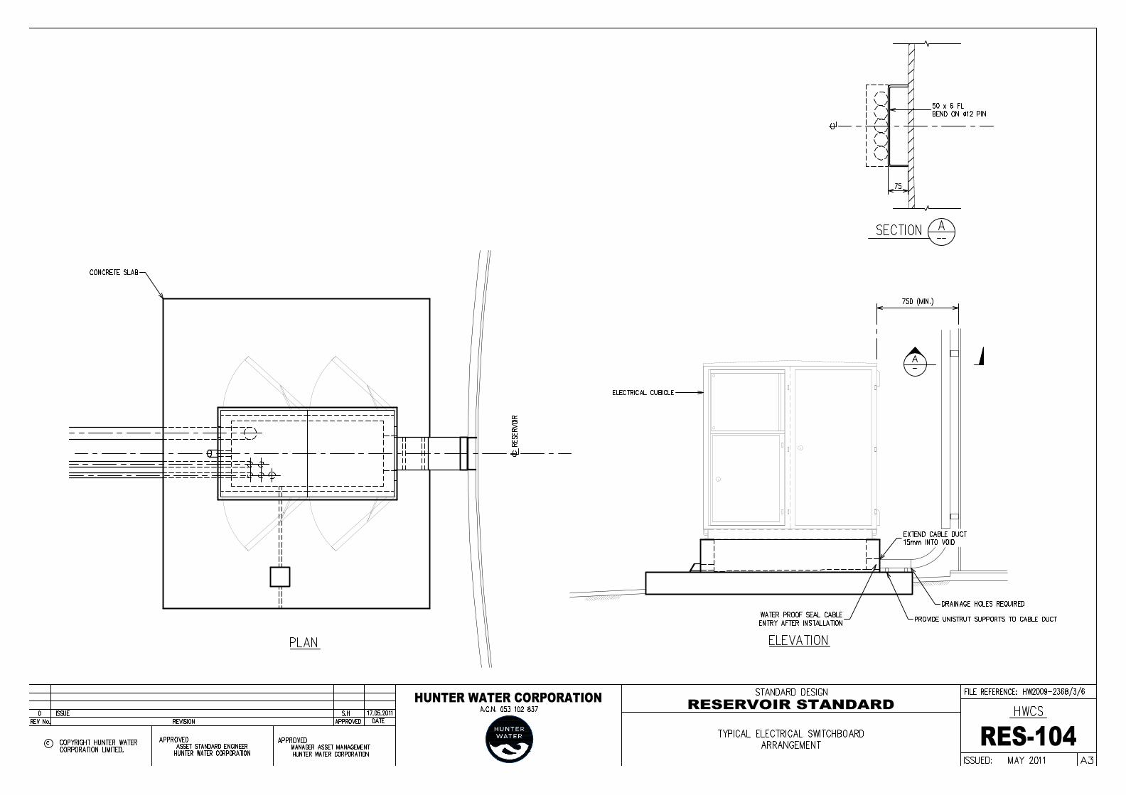
The switchboard is to be located outdoors and constructed in accordance with therequirements for outdoor type switchboards as detailed in HWC Standard ElectricalSpecification STS500.

SECTION 7 TANK / RESERVOIR STANDARD HUNTER WATER CORPORATIONMay 2011 27
The switchboard will comprise various compartments and components to serve manyfunctions. The main compartments are as follows: Metering of incoming power supply Main Distribution section complete with incomer switch, voltmeter/power meter, auxiliary
distribution circuit breakers and GPO Programmable logic controller (PLC), Telemetry and Instrumentation cubicle
All electrical equipment must be secured behind an internal door fitted with a lock that is“81/3” keyed. However, the electricity meters, all instrument displays, station controls and atleast one 230V AC power outlet shall be accessible by opening an external door with pad-lockable handles. All LV equipment requiring operator access such as voltmeter, GPO, lightswitch and circuit breakers shall be mounted internally and accessible via cut outs in theinner door.
Outdoor switchboards are to incorporate a security system comprising sensors fitted to theexternal doors. These sensors are to be connected to the PLC and telemetry to raise analarm as detailed in Hunter Water’s specification STS 105.
7.27.2.1 Metering of Incoming Power SupplyThis compartment houses the electricity meters which record kilowatt hours. A separateexternal door shall be fitted to this compartment to provide access to the Supply AuthorityMeter readers, without providing access to other controls.
Main Incomer Switch and Distribution Section
This provides isolation of the switchboard from the incoming power supply and distributespower to the site auxiliaries such as power points (GPO’s), lighting, security system andcontrols. Single phase switchboards will include a voltmeter and three phase switchboardswill include a power meter.
7.27.2.2 PLC Telemetry and Instrumentation CubicleThis houses the PLC, Telemetry equipment, control power supplies, GPO for technician’suse and field wiring terminals. The power supply for the PLC and telemetry equipment willhave battery backup.
The Telemetry equipment includes remote/radio telemetry unit (RTU) which is connected tothe PLC, a digital radio and an aerial. The RTU forwards and receives radio signals to andfrom a base station (for example, Gan Gan, Sugarloaf, etc.) which is connected to the HunterWater SCADA (supervisory control and data acquisition) system.
This system allows for remote monitoring and control of the reservoir. This is achieved by 2-way communication with the station PLC.
The PLC shall be a Schneider M340 type.
Typical SCADA screen page diagrams will be supplied by Hunter Water and marked up bythe designer as part of the design documentation for the particular installation.
7.27.2.3 Radio Path Survey
On completion of the Concept Design, the designer is to engage and pay for a Hunter Waterapproved supplier to undertake a radio survey and from this to nominate a base station,transmit and receive frequencies and remote terminal unit (RTU) number along with antennadirection/bearing to base, antenna mounting height and antenna size.
The designer must then seek approval from Hunter Water for the above.

SECTION 7 TANK / RESERVOIR STANDARD HUNTER WATER CORPORATIONMay 2011 28
7.27.3 LEVEL INSTRUMENTSEach reservoir will include the following level monitoring equipment: Hydrostatic type analogue level transmitter with a nominal range of 1.0 bar. Abnormal High Level alarm float switch Abnormal low level alarm float switch
The analogue level instrument will include: Level display on the Reservoir roof Level Display on the PLC/Telemetry and Instrumentation Cubicle internal door Surge protection unit at each end of the 4-20mA signal cabling
An outdoor electrical panel will be provided on the reservoir roof to house the Level display and surge protection Field terminals for level instrument and float switches Field terminals for security switches on roof access hatches
7.27.4 SECURITYThe Reservoir site will include a security system area in accordance with Standard TechnicalSpecification STS105. The security system is to comprise: appropriate HWC padlocks on access gates, hatch covers, valve pit covers and external
doors on electrical switchboard cabinets; and a switch-operated alarm system including proximity type switches on hatch covers,
electrical switchboard doors, reservoir roof hatches, reservoir stair access gate, passiveinfrared & voice alarm on reservoir near access stairway landing. All security switchesshall be individually connected to terminals in the main switchboard in accordance withHunter Water’s specification STS105.
7.27.5 LIGHTINGProvide sufficient lighting for after hours maintenance on: Reservoir access stairway and platforms. Reservoir security compound area including main electrical switchboard.
External lighting will be operated by a switch on the Distribution section of the siteswitchboard.
Lighting levels shall be in accordance with the requirements of STS500.
Lighting is not required on the roof of the reservoir.
7.27.6 SITE 230V GPOSThe following 230V general purpose outlets (GPOs) will be provided, with each GPOsupplied from a separate earth leakage circuit breaker:
One on the internal door of the Distribution section of the main switchboard
One inside the PLC/Telemetry/Instrumentation Panel for the technician’s use
7.27.7 LIGHTNING PROTECTIONProvide Lightning Protection in accordance with the requirements of STS500.

SECTION 7 TANK / RESERVOIR STANDARD HUNTER WATER CORPORATIONMay 2011 29
7.28 DESIGN DOCUMENTATION AND DRAWINGS
7.28.1 DESIGN DESIGNThe designer is to prepare a comprehensive designer’s report detailing the logic behind thefinal design. It should cover all requirements included in strategies, preliminary designreports and concept design reports.
The report shall be accompanied with the following:- Detailed drawings, calculations and specifications as required for the various components
of the system. Where applicable, a copy of the radio path survey report Where applicable approvals or letters of agreement from stakeholders/regulatory bodies
(eg Government Agencies, RTA, Mine Subsidence Board, etc) Agreement to easement rights Permit to enter land external to development
Prepare all design drawings in accordance with STS911.
7.28.2 ELECTRICAL DESIGNThe electrical design shall include (but not be limited to) the following drawings: Incoming supply and PLC I/O General arrangement of switchboards Power and Control schematics for all equipment PLC I/O Schematics for all equipment Telemetry Instrument loops Installation wiring diagrams for each item and instrument type Equipment and cabling layouts Light and small power layouts PLC layout
Standard electric drawings may be obtained from Hunter Water in electronic format. Theseshall be used as the basis for the design of the specific reservoir project drawing set.
All electrical design drawings shall comply with the requirements of Hunter Water’sspecification STS904.
7.28.3 OPERATING AND MAINTENANCEPrepare an information package and provide Operation and Maintenance manuals with thedetail design. The information is to be provided to the construction contractor who will thenupdate / complete the required information prior to submitting to the Corporation.
The information package shall be prepared in electronic format and shall include, but is notlimited to, the following items: Functional description of the Asset, including operating philosophy and any restrictions
on use (asset and components) Details (make, model etc) of all maintainable items Listing of applicable spare parts (inc. OEM part numbers) Frequency and maintenance procedures for all maintainable items Durability of non-maintainable items Design life of all major components (for example roof, access ladders)
SECTION 7 TANK / RESERVOIR STANDARD HUNTER WATER CORPORATIONMay 2011 30
APPENDIX A
Tank / Reservoir Standard Drawings