Hunky Dory Repair iPhone 4s Tear Down and Repair Guide
128
IPHONE 4S TEARDOWN AND REPAIR GUIDE HUN KY D ORY REPA IR
-
Upload
marc-mourning -
Category
Devices & Hardware
-
view
228 -
download
1
Transcript of Hunky Dory Repair iPhone 4s Tear Down and Repair Guide

IPHONE 4
S TEARDOW
N
AND REPA
IR G
UIDE
HU
NK
Y D
OR
Y R
EP A
I R

REPLACING LCD/DIGITIZER ASSEMBLY FOR IPHONE 4S MODELS

REMOVE THE BOTTOM BEZEL PENTALOBE SCREWS
Make sure to:• Use the correct pentalobe screw driver, we do not want strip
the bezel screws, sometimes they will strip and we wont be able to put them back into the phone, and we do not let phones leave our business with missing screws!

REMOVE THE BACK COVER
Make sure to:• Grip the back case with both your thumbs in the middle of
the phone, then push upwards and the back cover will slide right off and you can pull it from the phone.

REMOVE THE BATTERY SOCKET SCREWS
Make sure to:• Remember that these two screws are different sized, they
need to be in the correct position when the phone is reinstalled, so make sure to keep them in the right spot when laying out your screws, or organize them ins a screw tray with the label on them point out which screw they are for.

PRY THE BATTERY SOCKET FROM THE BOARD
Make sure to:• Use a plastic pry tool to remove the whole socket assembly
from the

REMOVE THE BOTTOM DOCK FLEX RIBBON
Make sure to:• ALWAYS USE A PLASTIC PRY TOOL• Cleanly pull it from the socket and move it out of the way

REMOVE THE BOTTOM SIGNAL ANTENNA
Make sure to:• Use a plastic pry tool for this as well, we do not want to
damage the shape of the antenna pinion, then it will have a hard time connecting back to the pinion notch.
• This is one of two antenna cables and is imperative to the signal of the phone so be careful and delicate

REMOVE THE EMBEDDED FLASH TAPE
Make sure to:• Cleanly pull this off, there is no real reason for it being here,
it is adhered to the back case and is going to come off when you remove the back cover, but If you leave it on it will cover the flash and incorrect lighting will occur.

REMOVE THE TOP RIBBON BRACKET SCREWS
Make sure to:• Pull these off individually, they are all different sizes.• When you lay the screws out, keep them in their general
direction, no screw fits in another hole correctly.• Make sure not to lose any of these screws

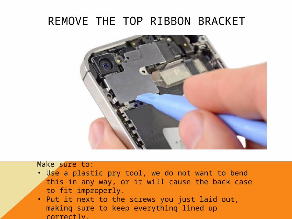
REMOVE THE TOP RIBBON BRACKER
Make sure to:• Use a plastic pry tool, we do not want to bend this in any
way, or it will cause the back case to fit improperly.• Put it next to the screws you just laid out, making sure to
keep everything lined up correctly.

REMOVE THE CAMERA RIBBON AND THE CAMERA
Make sure to:• Use a plastic pry tool, we do not want to damage the rubber
stopper or the ribbon it self.• Pull the camera all the way out using the plastic pry tool and
tweezers at the same time.

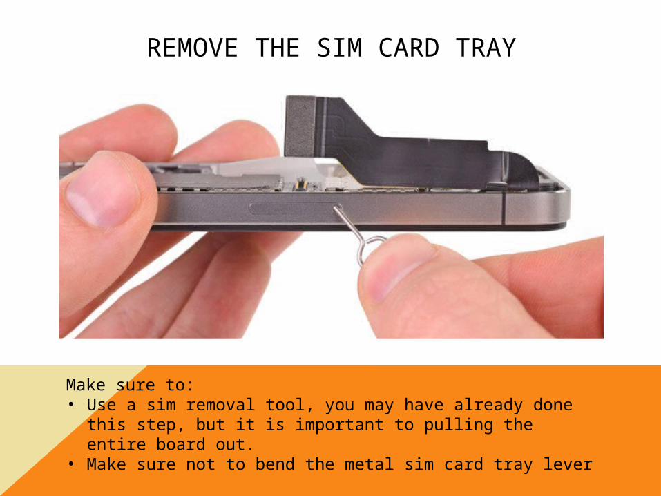
REMOVE THE SIM CARD TRAY
Make sure to:• Use a sim removal tool, you may have already done this
step, but it is important to pulling the entire board out.• Make sure not to bend the metal sim card tray lever

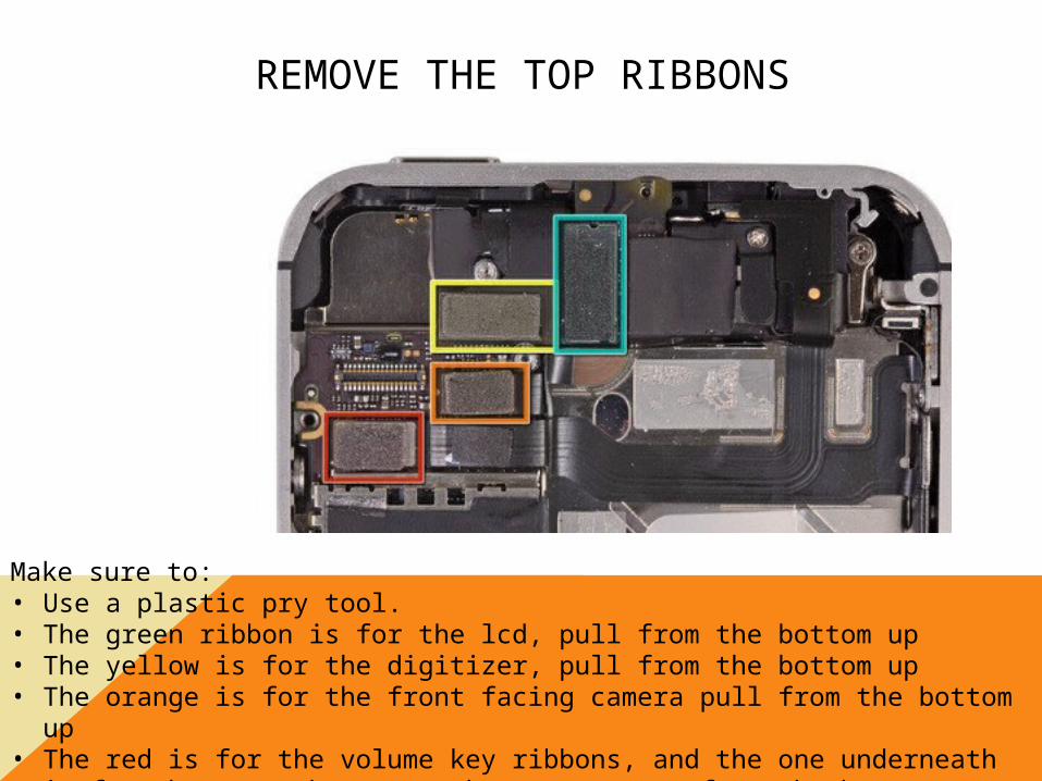
REMOVE THE TOP RIBBONS
Make sure to:• Use a plastic pry tool.• The green ribbon is for the lcd, pull from the bottom up• The yellow is for the digitizer, pull from the bottom up• The orange is for the front facing camera pull from the bottom up• The red is for the volume key ribbons, and the one underneath is for the
power button, make sure to pry from the bottom up.

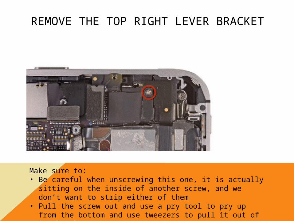
REMOVE THE TOP RIGHT LEVER BRACKET
Make sure to:• Be careful when unscrewing this one, it is actually sitting on
the inside of another screw, and we don’t want to strip either of them
• Pull the screw out and use a pry tool to pry up from the bottom and use tweezers to pull it out of its bracket.

REMOVE THE SCREW UNDERNEATH THE BRACKET LEVER
Make sure to:• Use a flathead for this, its one of the main board screws and
keeps the copper contacts down on the bottom for the earpiece and is very important

REMOVE THE WIFI ANTENNA
Make sure to:• Use a plastic pry tool to pry it up from the board, pull it from
the top and not from the left side, sometimes prying up from the left can pop the pinion rack as well as peel the wifi antenna
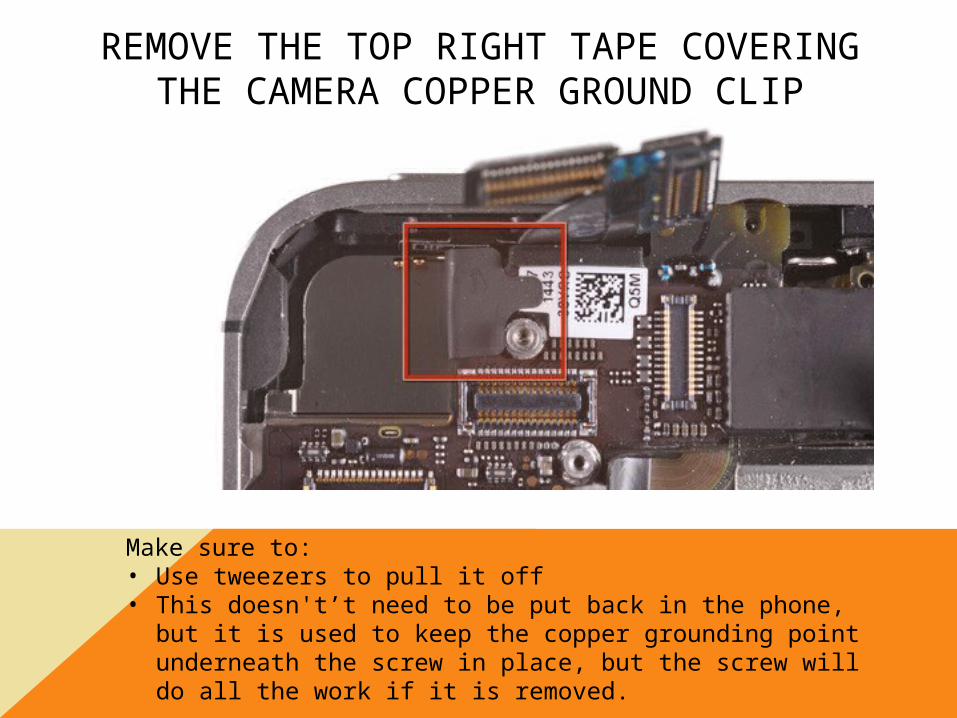
REMOVE THE TOP RIGHT TAPE COVERING THE CAMERA COPPER
GROUND CLIP
Make sure to:• Use tweezers to pull it off• This doesn't’t need to be put back in the phone, but it is
used to keep the copper grounding point underneath the screw in place, but the screw will do all the work if it is removed.

REMOVE THE MIDDLE LEFT BOARD SCREW
Make sure to:• Keep this screw in the correct layout, it is interchangeable
but we want everything to go back into place like it was when we removed it
• It is imperative to keep the contacts down for the vibrate motor, so don’t lose it.

PULL THE BOARD FROM THE MID FRAME
Make sure to:• Push up and then pull it in an angular upwards fashion from
the bottom of the phone near the speaker housing and dock assembly
• Make sure to remove all of the ribbon flex sockers out of the way, we do not want them to snag and then tear.

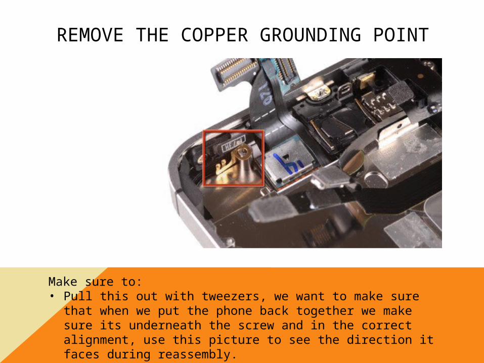
REMOVE THE COPPER GROUNDING POINT
Make sure to:• Pull this out with tweezers, we want to make sure that when
we put the phone back together we make sure its underneath the screw and in the correct alignment, use this picture to see the direction it faces during reassembly.

REMOVE THE VIBRATE MOTOR FROM THE BACK CASE
Make sure to:• Use a plastic pry tool to remove it from the rear case, we
want to make sure not to bend the plate that holds the two copper springs, if they do not sit correctly underneath the board, they will not hit the contacts on the board and the vibrate motor will not work.

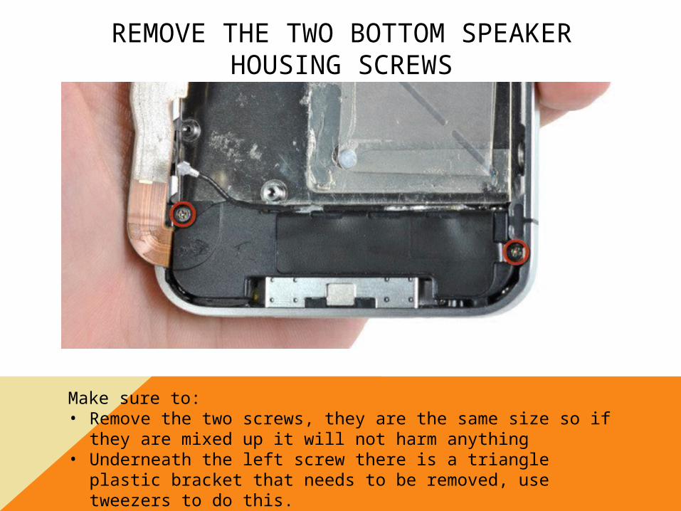
REMOVE THE TWO BOTTOM SPEAKER HOUSING SCREWS
Make sure to:• Remove the two screws, they are the same size so if they are
mixed up it will not harm anything• Underneath the left screw there is a triangle plastic bracket
that needs to be removed, use tweezers to do this.

REMOVE THE LEFT SIDE SPEAKER HOUSING TRIANGLE BRACKET
MAKE SURE TO KEEP THIS WITH THE SPEAKER HOUSING SCREWS!

REMOVE THE TAPE THAT COVERS THE TOP LEFT CORNER DISPLAY ASSEMBLY
SCREW
Make sure to:• Pull this off with tweezers, its not needed for reassembly, but
make sure to take it off before unscrewing, if you don’t it can sometimes cause the screw to strip.

REMOVE THE TOP LEFT DISPLAY ASSEMBLY SCREW
Make sure to:• Remove this screw correctly, don’t let it strip, its one of the
main screws that keeps gaps from occurring when putting the new display assembly on.
• Keep this screw with the other three corner screws, they do not fit any other position inside of the phone

REMOVE THE TOP RIGHT CORNER DISPLAY ASSEMBLY SCREW
Make sure to:• Not strip this screw!• Keep it with the other three corner screws• This screw is will only fit this thread and should not be mixed
up.

REMOVE THE BOTTOM RIGHT DISPLAY ASSEMBLY SCREW
Make sure to:• Not strip this screw!• Keep it with the other three corner
screws• This screw is will only fit this thread
and should not be mixed up.

REMOVE THE BOTTOM LEFT DISPLAY ASSEMBLY SCREW
Make sure to:• Not strip this screw!• Keep it with the other three corner
screws• This screw is will only fit this thread
and should not be mixed up.

LOOSEN THE RIGHT SIDE MID-FRAME SCREWS
Make sure to:• Unscrew these, they do not have to be removed, but if they
are it is sometimes hard to align everything correctly, as there is metal washers underneath it.
• Loosen them until you can see a gap between the washers and the display assembly frame brackets
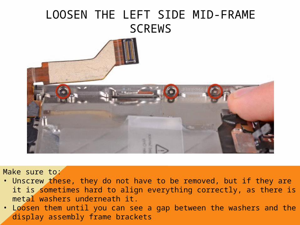
LOOSEN THE LEFT SIDE MID-FRAME SCREWS
Make sure to:• Unscrew these, they do not have to be removed, but if they are it is
sometimes hard to align everything correctly, as there is metal washers underneath it.
• Loosen them until you can see a gap between the washers and the display assembly frame brackets

REMOVE THE WHOLE LCD ASSEMBLY
Make sure to:• Use a plastic pry tool to separate the lcd assembly from the midframe,
sometimes a little heat will make the adhesive come off a little easier• Try the best you can to pull the cables through the whole in the midframe
and make sure that you keep the LCD intact as much as you can, the recycle value of them is imperative to our organization.

PUTTING THE NEW DISPLAY ASSEMBLY ON
• Make sure you pull the static covering that is on the back of the display, if this is not removed it will cause heat damage to the LCD and make it in operable.
• Put the old LCD inside of the bubble wrap that the new one is, REDUCE REUSE RECYCLE
• Make sure to line the brackets up in their correct positions, we don’t want any gaps occurring in between the mid-frame and the LCD
• Align the home button correctly, it will be pulled from the old display, use tweezers to remove the rubber from the old display, it is thin so be careful, we don’t want misaligned falling home buttons
• Pull the LCD and digitizer ribbon all the way through the mid-frame hole, we need no slack when we put the LCD into place
• Start screwing the corner screws in first, then tighten the midframe schools
• Then use the disassembly instructions backwards to correctly re-assemble the phone in the correct order.

REPLACING THE IPHONE 4S BOTTOM DOCK ASSEMBLY

REMOVE THE BOTTOM BEZEL PENTALOBE SCREWS
Make sure to:• Use the correct pentalobe screw driver, we do not want strip
the bezel screws, sometimes they will strip and we wont be able to put them back into the phone, and we do not let phones leave our business with missing screws!

REMOVE THE BACK COVER
Make sure to:• Grip the back case with both your thumbs in the middle of
the phone, then push upwards and the back cover will slide right off and you can pull it from the phone.

REMOVE THE BATTERY SOCKET SCREWS
Make sure to:• Remember that these two screws are different sized, they
need to be in the correct position when the phone is reinstalled, so make sure to keep them in the right spot when laying out your screws, or organize them ins a screw tray with the label on them point out which screw they are for.

PRY THE BATTERY SOCKET FROM THE BOARD
Make sure to:• Use a plastic pry tool to remove the whole socket assembly
from the

REMOVE THE BOTTOM DOCK FLEX RIBBON
Make sure to:• ALWAYS USE A PLASTIC PRY TOOL• Cleanly pull it from the socket and move it out of the way

REMOVE THE BOTTOM SIGNAL ANTENNA
Make sure to:• Use a plastic pry tool for this as well, we do not want to
damage the shape of the antenna pinion, then it will have a hard time connecting back to the pinion notch.
• This is one of two antenna cables and is imperative to the signal of the phone so be careful and delicate

REMOVE THE EMBEDDED FLASH TAPE
Make sure to:• Cleanly pull this off, there is no real reason for it being here,
it is adhered to the back case and is going to come off when you remove the back cover, but If you leave it on it will cover the flash and incorrect lighting will occur.

REMOVE THE TOP RIBBON BRACKET SCREWS
Make sure to:• Pull these off individually, they are all different sizes.• When you lay the screws out, keep them in their general
direction, no screw fits in another hole correctly.• Make sure not to lose any of these screws

REMOVE THE TOP RIBBON BRACKER
Make sure to:• Use a plastic pry tool, we do not want to bend this in any
way, or it will cause the back case to fit improperly.• Put it next to the screws you just laid out, making sure to
keep everything lined up correctly.

REMOVE THE CAMERA RIBBON AND THE CAMERA
Make sure to:• Use a plastic pry tool, we do not want to damage the rubber
stopper or the ribbon it self.• Pull the camera all the way out using the plastic pry tool and
tweezers at the same time.

REMOVE THE SIM CARD TRAY
Make sure to:• Use a sim removal tool, you may have already done this
step, but it is important to pulling the entire board out.• Make sure not to bend the metal sim card tray lever
REMOVE THE TOP RIBBONS
Make sure to:• Use a plastic pry tool.• The green ribbon is for the lcd, pull from the bottom up• The yellow is for the digitizer, pull from the bottom up• The orange is for the front facing camera pull from the bottom up• The red is for the volume key ribbons, and the one underneath is for the
power button, make sure to pry from the bottom up.
REMOVE THE TOP RIGHT LEVER BRACKET
Make sure to:• Be careful when unscrewing this one, it is actually sitting on
the inside of another screw, and we don’t want to strip either of them
• Pull the screw out and use a pry tool to pry up from the bottom and use tweezers to pull it out of its bracket.

REMOVE THE SCREW UNDERNEATH THE BRACKET LEVER
Make sure to:• Use a flathead for this, its one of the main board screws and
keeps the copper contacts down on the bottom for the earpiece and is very important

REMOVE THE WIFI ANTENNA
Make sure to:• Use a plastic pry tool to pry it up from the board, pull it from
the top and not from the left side, sometimes prying up from the left can pop the pinion rack as well as peel the wifi antenna

REMOVE THE TOP RIGHT TAPE COVERING THE CAMERA COPPER
GROUND CLIP
Make sure to:• Use tweezers to pull it off• This doesn't’t need to be put back in the phone, but it is
used to keep the copper grounding point underneath the screw in place, but the screw will do all the work if it is removed.

REMOVE THE MIDDLE LEFT BOARD SCREW
Make sure to:• Keep this screw in the correct layout, it is interchangeable
but we want everything to go back into place like it was when we removed it
• It is imperative to keep the contacts down for the vibrate motor, so don’t lose it.

PULL THE BOARD FROM THE MID FRAME
Make sure to:• Push up and then pull it in an angular upwards fashion from
the bottom of the phone near the speaker housing and dock assembly
• Make sure to remove all of the ribbon flex sockers out of the way, we do not want them to snag and then tear.

REMOVE THE COPPER GROUNDING POINT
Make sure to:• Pull this out with tweezers, we want to make sure that when
we put the phone back together we make sure its underneath the screw and in the correct alignment, use this picture to see the direction it faces during reassembly.

REMOVE THE VIBRATE MOTOR FROM THE BACK CASE
Make sure to:• Use a plastic pry tool to remove it from the rear case, we
want to make sure not to bend the plate that holds the two copper springs, if they do not sit correctly underneath the board, they will not hit the contacts on the board and the vibrate motor will not work.
REMOVE THE TWO BOTTOM SPEAKER HOUSING SCREWS
Make sure to:• Remove the two screws, they are the same size so if they are
mixed up it will not harm anything• Underneath the left screw there is a triangle plastic bracket
that needs to be removed, use tweezers to do this.

REMOVE THE LEFT SIDE SPEAKER HOUSING TRIANGLE BRACKET
MAKE SURE TO KEEP THIS WITH THE SPEAKER HOUSING SCREWS!

REMOVE THE BOTTOM SPEAKER HOUSING
Make sure to;• Use a plastic pry tool, we do not want to bend the metal clips
that are on the top of the housing, they keep the speaker housing pushed in to protect the actual speakers and microphone on the bottom of the dock assembly

REMOVE THE BOTTOM LEFT DOCK ASSEMBLY SCREW TAPE
Make sure to:• Use tweezers to remove this, we don’t want to bend or rip
the old dock assembly, we may be able to recycle it.• Remove it all the way off, if you don’t, it can sometimes
cause the screw to strip

REMOVE THE LOCK ON THE FPC LOCK
Make sure to:• Use a plastic pry tool to pop this up, do not use a flat head!
Using a flathead will sometimes cause the FPC door to unhinge, and then the home button ribbon cannot be used again on this assembly, and since we are recycling it, we want to keep it in the best condition we can.

REMOVE THE HOME BUTTON FLEX RIBBON
Make sure to:• Use a pair of tweezers to pull the ribbon out of the FPC lock,
make sure to be careful we don’t want to damage or rip the ribbon, as we are not replacing it in this process, so the ribbon will be reused.

PULL THE BOTTOM MICROPHONE RUBBER HOUSING
Make sure to:• Use a plastic pry tool to take it out of the metal hole• We do not want to rip, damage or tear this rubber housing, it
is used to amplify the microphone.• We will be taking it off this dock assembly and using it for
the replacement dock assembly.

REMOVE THE LEFT AND RIGHT BOTTOM DOCK ASSEMBLY SCREWS
Make sure to:• Unscrew this dock screws very carefully, we do not want them to be
damaged, as well as we do not want them to lock up and strip, this will cause the dock to be permanently connected to the dock assembly, and then there is nothing that can be done.
• Keep them together in your layout, there are unlike any other screw in the assembly

REMOVE THE ADHESIVE PADS FOR THE DOCK ASSEMBLY
In order to correctly pull the whole assembly off, we have to use plastic pry tools to remove the adhesive pads that are keeping the entire assembly in place, pull it off as gently as you can, we want to be able to recycle these parts in one piece

REMOVE THE ENTIRE DOCK ASSEMBLY FROM THE MID-FRAME
Make sure to:• Use a plastic pry tool to pull the dock assembly from the
phone.• Make sure that the rubber speaker housing cover has been
removed from its metal tube caddy.• Pry up and out and remove the dock assembly

REPLACING THE DOCK ASSEMBLY WITH A NEW DOCK ASSEMBLY
• Now that we have the whole assembly removed from the phone, we can now place the new unit inside of the rear case
• Remove all of the static paper that is covering the adhesive on the new dock assembly
• Take the rubber microphone housing and slide it over the bottom right microphone plate on the new dock assembly
• Fit the new dock assembly into the rear case, making sure the 30 pin connecter is properly aligned, test it by inserting a 30pin cable.
• Now that it is in place, put the home button ribbon into the FPC lock using a pair of tweezers and a plastic pry tool to close the FPC lock.
• Screw the two dock assembly screws into place
• Follow this guide backwards to reassemble the phone in the proper order.

REPLACING THE POWER BUTTON AND SENSOR RIBBON ASSEMBLY

REMOVE THE BOTTOM BEZEL PENTALOBE SCREWS
Make sure to:• Use the correct pentalobe screw driver, we do not want strip
the bezel screws, sometimes they will strip and we wont be able to put them back into the phone, and we do not let phones leave our business with missing screws!

REMOVE THE BACK COVER
Make sure to:• Grip the back case with both your thumbs in the middle of
the phone, then push upwards and the back cover will slide right off and you can pull it from the phone.

REMOVE THE BATTERY SOCKET SCREWS
Make sure to:• Remember that these two screws are different sized, they
need to be in the correct position when the phone is reinstalled, so make sure to keep them in the right spot when laying out your screws, or organize them ins a screw tray with the label on them point out which screw they are for.

PRY THE BATTERY SOCKET FROM THE BOARD
Make sure to:• Use a plastic pry tool to remove the whole socket assembly
from the

REMOVE THE BOTTOM DOCK FLEX RIBBON
Make sure to:• ALWAYS USE A PLASTIC PRY TOOL• Cleanly pull it from the socket and move it out of the way

REMOVE THE BOTTOM SIGNAL ANTENNA
Make sure to:• Use a plastic pry tool for this as well, we do not want to
damage the shape of the antenna pinion, then it will have a hard time connecting back to the pinion notch.
• This is one of two antenna cables and is imperative to the signal of the phone so be careful and delicate

REMOVE THE EMBEDDED FLASH TAPE
Make sure to:• Cleanly pull this off, there is no real reason for it being here,
it is adhered to the back case and is going to come off when you remove the back cover, but If you leave it on it will cover the flash and incorrect lighting will occur.

REMOVE THE TOP RIBBON BRACKET SCREWS
Make sure to:• Pull these off individually, they are all different sizes.• When you lay the screws out, keep them in their general
direction, no screw fits in another hole correctly.• Make sure not to lose any of these screws
REMOVE THE TOP RIBBON BRACKET
Make sure to:• Use a plastic pry tool, we do not want to bend this in any
way, or it will cause the back case to fit improperly.• Put it next to the screws you just laid out, making sure to
keep everything lined up correctly.

REMOVE THE CAMERA RIBBON AND THE CAMERA
Make sure to:• Use a plastic pry tool, we do not want to damage the rubber
stopper or the ribbon it self.• Pull the camera all the way out using the plastic pry tool and
tweezers at the same time.

REMOVE THE SIM CARD TRAY
Make sure to:• Use a sim removal tool, you may have already done this
step, but it is important to pulling the entire board out.• Make sure not to bend the metal sim card tray lever

REMOVE THE TOP RIBBONS
Make sure to:• Use a plastic pry tool.• The green ribbon is for the lcd, pull from the bottom up• The yellow is for the digitizer, pull from the bottom up• The orange is for the front facing camera pull from the bottom up• The red is for the volume key ribbons, and the one underneath is for the
power button, make sure to pry from the bottom up.

REMOVE THE TOP RIGHT LEVER BRACKET
Make sure to:• Be careful when unscrewing this one, it is actually sitting on
the inside of another screw, and we don’t want to strip either of them
• Pull the screw out and use a pry tool to pry up from the bottom and use tweezers to pull it out of its bracket.

REMOVE THE SCREW UNDERNEATH THE BRACKET LEVER
Make sure to:• Use a flathead for this, its one of the main board screws and
keeps the copper contacts down on the bottom for the earpiece and is very important

REMOVE THE WIFI ANTENNA
Make sure to:• Use a plastic pry tool to pry it up from the board, pull it from
the top and not from the left side, sometimes prying up from the left can pop the pinion rack as well as peel the wifi antenna

REMOVE THE TOP RIGHT TAPE COVERING THE CAMERA COPPER
GROUND CLIP
Make sure to:• Use tweezers to pull it off• This doesn't’t need to be put back in the phone, but it is
used to keep the copper grounding point underneath the screw in place, but the screw will do all the work if it is removed.

REMOVE THE MIDDLE LEFT BOARD SCREW
Make sure to:• Keep this screw in the correct layout, it is interchangeable
but we want everything to go back into place like it was when we removed it
• It is imperative to keep the contacts down for the vibrate motor, so don’t lose it.

PULL THE BOARD FROM THE MID FRAME
Make sure to:• Push up and then pull it in an angular upwards fashion from
the bottom of the phone near the speaker housing and dock assembly
• Make sure to remove all of the ribbon flex sockers out of the way, we do not want them to snag and then tear.

REMOVE THE COPPER GROUNDING POINT
Make sure to:• Pull this out with tweezers, we want to make sure that when
we put the phone back together we make sure its underneath the screw and in the correct alignment, use this picture to see the direction it faces during reassembly.

REMOVE THE METAL BRACKET THAT HOLDS THE FRONT FACING CAMERA
Make sure to:• Pry the metal bracket up with a plastic pry tool, we do not
want the holding points to bend, as they keep the front facing camera in place
• Then take a pair of tweezers and pull the metal bracket all the way out

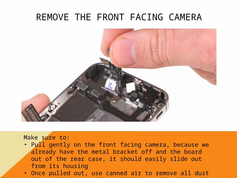
REMOVE THE FRONT FACING CAMERA
Make sure to:• Pull gently on the front facing camera, because we already
have the metal bracket off and the board out of the rear case, it should easily slide out from its housing
• Once pulled out, use canned air to remove all dust from the camera, and put it into a safe place so it does not get damaged.

REMOVE THE POWER BUTTON BRACKET SCREWS
Make sure to:• Be careful when unscrewing these, we do not want them to
strip, then the bracket will not tighten all the way, and it will cause the power button to miss align itself, and it will not work correctly.

PULL THE POWER BUTTON BRACKET OUT OF THE PHONE
Make sure to:• Grab a pair of tweezers and pull the bracket out of its slot,
making sure to pull the power button out as well so it does not get lost.
• Pull from the right side if the power button is facing you, the left side if the screw holes are facing you.

REMOVE THE POWER BUTTON/SENSOR RIBBON FROM THE CASE
Make sure to:• Use a plastic pry tool to pry up underneat the ribbon itself, it
wraps around the metal rectangular earpiece, which will have to be removed in the next couple of steps
• The ribbon should not be pulled all the way off in this step, just getting the adhesive up so for when we do pull the ribbon all the way up.
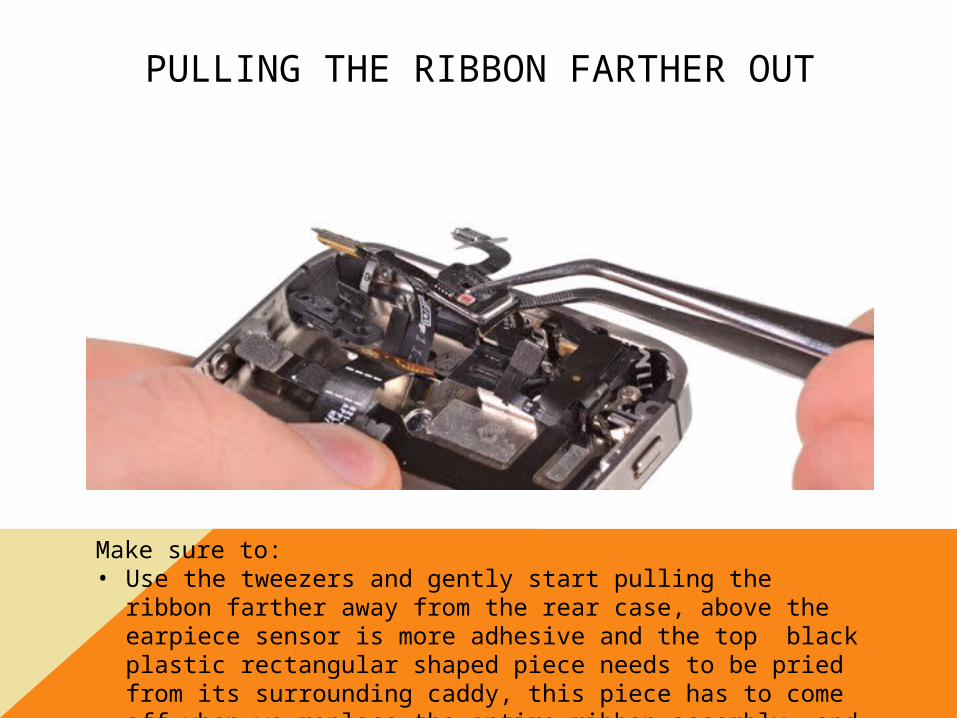
PULLING THE RIBBON FARTHER OUT
Make sure to:• Use the tweezers and gently start pulling the ribbon farther
away from the rear case, above the earpiece sensor is more adhesive and the top black plastic rectangular shaped piece needs to be pried from its surrounding caddy, this piece has to come off when we replace the entire ribbon assembly, and helps wrap the ribbon around the earpiece.

REMOVE THE FULL RIBBON FROM THE CASE
Make sure to:• Check to make sure all of the adhesive points on the ribbon are raised up
from the rear case, even though we are completely removing and replacing the whole ribbon, we want to keep it intact as much as we can for recycling
• Make sure all of the plastic pieces that are snapping the earpiece in place stay together, we will be using part of them for the new ribbon.

PULL THE EARPIECE FROM THE RIBBON
Make sure to:• Be aware of the copper contact points on the earpiece, the
sensor ribbon wraps around and snaps into a small rectangular control board, the top plastic we will need to remove with tweezers and keep for the new ribbon.
• Make sure the copper points are not damage or broken in any manner.

PULL THE POWER BUTTON BRACKET FROM THE RIBBON ASSEMBLY
Make sure to:• Use a plastic pry tool to remove the popcap from the black
plastic cradle that it is adhered to.• We will be using this cradle for the new ribbon, so make sure
to leave it undamaged.

ASSEMBLING THE NEW RIBBON, AND THE ENTIRE PHONE
• Take the earpiece in your hand, making sure the copper points are facing upwards, as if the board is about to be place on top of it, align the earpiece on the new ribbon, the same place it was when you removed it. Then wrap the rest of the ribbon around it, securing it in place with the plastic rectangle.
• Now take the power button cradle and undue the static covering tape that covers the adhesive underneath the pop cap. Take the pop cap and wrap it around the cradle, making sure to correctly align it on the cradle so that the power button will correctly be pressed.
• First, align the new cradle and pop cap into position and screw the cradle back into place. Then remove the static tape covering the adhesive points on the bottom of the ribbon, then align the ribbon and place it inside of the phone, making sure that everything is correctly seated so that the earpiece and new power button are functional once the phone is completely assembled.
• Now that the power button is in place, make sure it works by pressing down on it a few times, we do not want hard presses, it should pop up and down with ease
• Reassemble the phone working backwards from the disassembly guide, making sure that the phone has been tested multiple times once it is turned on

REPLACING THE VOLUME KEY AND MUTE SWITCH RIBBON ASSEMBLY

REMOVE THE BOTTOM BEZEL PENTALOBE SCREWS
Make sure to:• Use the correct pentalobe screw driver, we do not want strip
the bezel screws, sometimes they will strip and we wont be able to put them back into the phone, and we do not let phones leave our business with missing screws!

REMOVE THE BACK COVER
Make sure to:• Grip the back case with both your thumbs in the middle of
the phone, then push upwards and the back cover will slide right off and you can pull it from the phone.

REMOVE THE BATTERY SOCKET SCREWS
Make sure to:• Remember that these two screws are different sized, they
need to be in the correct position when the phone is reinstalled, so make sure to keep them in the right spot when laying out your screws, or organize them ins a screw tray with the label on them point out which screw they are for.

PRY THE BATTERY SOCKET FROM THE BOARD
Make sure to:• Use a plastic pry tool to remove the whole socket assembly
from the

REMOVE THE BOTTOM DOCK FLEX RIBBON
Make sure to:• ALWAYS USE A PLASTIC PRY TOOL• Cleanly pull it from the socket and move it out of the way

REMOVE THE BOTTOM SIGNAL ANTENNA
Make sure to:• Use a plastic pry tool for this as well, we do not want to
damage the shape of the antenna pinion, then it will have a hard time connecting back to the pinion notch.
• This is one of two antenna cables and is imperative to the signal of the phone so be careful and delicate

REMOVE THE EMBEDDED FLASH TAPE
Make sure to:• Cleanly pull this off, there is no real reason for it being here,
it is adhered to the back case and is going to come off when you remove the back cover, but If you leave it on it will cover the flash and incorrect lighting will occur.

REMOVE THE TOP RIBBON BRACKET SCREWS
Make sure to:• Pull these off individually, they are all different sizes.• When you lay the screws out, keep them in their general
direction, no screw fits in another hole correctly.• Make sure not to lose any of these screws

REMOVE THE TOP RIBBON BRACKET
Make sure to:• Use a plastic pry tool, we do not want to bend this in any
way, or it will cause the back case to fit improperly.• Put it next to the screws you just laid out, making sure to
keep everything lined up correctly.

REMOVE THE CAMERA RIBBON AND THE CAMERA
Make sure to:• Use a plastic pry tool, we do not want to damage the rubber
stopper or the ribbon it self.• Pull the camera all the way out using the plastic pry tool and
tweezers at the same time.
REMOVE THE SIM CARD TRAY
Make sure to:• Use a sim removal tool, you may have already done this
step, but it is important to pulling the entire board out.• Make sure not to bend the metal sim card tray lever

REMOVE THE TOP RIBBONS
Make sure to:• Use a plastic pry tool.• The green ribbon is for the lcd, pull from the bottom up• The yellow is for the digitizer, pull from the bottom up• The orange is for the front facing camera pull from the bottom up• The red is for the volume key ribbons, and the one underneath is for the
power button, make sure to pry from the bottom up.

REMOVE THE TOP RIGHT LEVER BRACKET
Make sure to:• Be careful when unscrewing this one, it is actually sitting on
the inside of another screw, and we don’t want to strip either of them
• Pull the screw out and use a pry tool to pry up from the bottom and use tweezers to pull it out of its bracket.

REMOVE THE SCREW UNDERNEATH THE BRACKET LEVER
Make sure to:• Use a flathead for this, its one of the main board screws and
keeps the copper contacts down on the bottom for the earpiece and is very important

REMOVE THE WIFI ANTENNA
Make sure to:• Use a plastic pry tool to pry it up from the board, pull it from
the top and not from the left side, sometimes prying up from the left can pop the pinion rack as well as peel the wifi antenna

REMOVE THE TOP RIGHT TAPE COVERING THE CAMERA COPPER
GROUND CLIP
Make sure to:• Use tweezers to pull it off• This doesn't’t need to be put back in the phone, but it is
used to keep the copper grounding point underneath the screw in place, but the screw will do all the work if it is removed.

REMOVE THE MIDDLE LEFT BOARD SCREW
Make sure to:• Keep this screw in the correct layout, it is interchangeable
but we want everything to go back into place like it was when we removed it
• It is imperative to keep the contacts down for the vibrate motor, so don’t lose it.

PULL THE BOARD FROM THE MID FRAME
Make sure to:• Push up and then pull it in an angular upwards fashion from
the bottom of the phone near the speaker housing and dock assembly
• Make sure to remove all of the ribbon flex sockers out of the way, we do not want them to snag and then tear.
REMOVE THE COPPER GROUNDING POINT
Make sure to:• Pull this out with tweezers, we want to make sure that when
we put the phone back together we make sure its underneath the screw and in the correct alignment, use this picture to see the direction it faces during reassembly.

REMOVE THE METAL BRACKET THAT HOLDS THE FRONT FACING CAMERA
Make sure to:• Pry the metal bracket up with a plastic pry tool, we do not
want the holding points to bend, as they keep the front facing camera in place
• Then take a pair of tweezers and pull the metal bracket all the way out
REMOVE THE FRONT FACING CAMERA
Make sure to:• Pull gently on the front facing camera, because we already
have the metal bracket off and the board out of the rear case, it should easily slide out from its housing
• Once pulled out, use canned air to remove all dust from the camera, and put it into a safe place so it does not get damaged.

REMOVE THE UPPER ANTENNA BRACKET SCREW
Make sure to:• Gently remove this screw, it helps hold one of the upper
antenna ribbons into place, glued to the top of the head phone jacket.
• Lay out the screw so you know the correct position, and always check back at this picture for the alignment of the upper antenna

REMOVE THE UPPER ANTENNA FROM THE TOP OF THE HEADPHONE JACK
Make sure to:• Always use the spudger or plastic pry tool to remove this antenna, it is
connected to the wifi pinion that sets the signal for wifi, never use a metal flathead, we will be reusing this, so we do not want to damage the ribbon.
• Once the adhesive is peeled back, use the tweezers to fully remove it from the phone.

PRY THE HEADPHONE JACK FROM THE REAR CASE
Make sure to:• Use a plastic pry tool, even though this individual piece is
going to be replace, we do not want to use a flathead screw driver and risk any damage done to the phone.
• The headphone jack will not be pulled out all the way, but moved away from the rear case to start disassembling the ribbon from the phone.

• REMOVE THE TOP MICROPHONE FROM THE REAR CASE
Make sure to:• Remember that this one is a little difficult, there is some adhesive that
holds it into the small cradle it sit on, so stick a plastic pry tool in between the metal and the microphone and pry it away from the rear case.
• Clean all of the adhesive from the spot where the microphone was attached, we want it as clear as possible so that the new microphone sits in place correctly.

REMOVE THE SCREW THAT SECURES THE OTHER UPPER ANTENNA TO THE
FRAME
Make sure to:• Remember that this ribbon is built into the midframe, but
this secure the points to the board, and also provides a more secure foundation for the mute switch and volume key frame plates and caddy

REMOVE THE SCREWS FOR THE VOLUME SWITCH AND MUTE SWITCH BRACKETS
Make sure to:• Remember that these 4 screws hold the brackets that keep
the volume keys in the correct position so that they sit in the midframe correctly, and they always help secure the bracket that holds the mute switch into place, this is really important as it holds the mute switch flush with the frame so that the button can actually be used.

PULL THE METAL VIBRATE SWITCH BRACKET FROM THE REAR CASE
Make sure to:• Use a pair of tweezers and not any other kind of tool. We do not want this
bracket to bend in any manner, as it is integral to the foundation of the mute switch
• If you look inside of the bracket, on the bottom right side you should see a small black plastic lever, this lever is what actually makes the vibrate switch work correctly.
• Make sure to note the down position of the lever, it will need to be in the same spot during reassembly.

REMOVE THE ENTIRE RIBBON FROM THE REAR CASE
Make sure to:• Grip the ribbon from the volume key and mute switch brackets, and
carefully peel it from the back case. Sometimes depending on the factory it was made, the ribbon will overlap onto the power button sensor ribbon, and we do not want to rip the sensor ribbon or damage it in any way, so make sure to hit all of the adhesive points on the bottom of the ribbon with the pry tool before completely removing the ribbon itself.

REMOVE THE MUTE SWITCH BRACKET CADDY FROM THE RIBBON
Make sure to:• Remember that this is an important part of the mute switch, and without it
we cannot put the new ribbon in place. Use a plastic pry tool to pry it up from the physical lever/switch that moves the metal mute button up and down
• There is some black rubber edging that sits on the top of the bracket that faces the actual button, make sure this stays intact or it will not sit flush with the physical button.

REMOVING THE VOLUME BUTTON PLATE FROM THE VOLUME POPCAPS
Make sure to:• Start with the ribbon on the back of the plate that faces the board of the
phone, the pop caps wrap around the metal plate frame, and help shape the alignment on the frame.
• Make sure all adhesive and tape is removed from the plate once you peel the pop caps off, we do not want any misalignment or rising to occur with the new ribbon in place.

ASSEMBLING THE NEW RIBBON AND REASSEMBLING THE PHONE
• Now that we have the mute switch bracket and the volume key frame removed from the old ribbon, we will need to put it back into place on the new ribbon. Take all of the antistatic tape that covers the adhesive points on the ribbon off, then align the volume key pop caps and adhesive wrap on the metal frame, noticing the alignment shapes that guide you to which side faces the buttons, and what side faces inside of the phone towards the board. Make sure to press down firmly so that all of the adhesive is firmly in place and keeps the pop caps aligned, we do not want any gaps or wrinkles in between the ribbon and the plate.
• Now take the vibrate switch bracket, use a small dot of glue (the size of a pin head) and dabble it on the vibrate switch lever pad, making sure it does not touch or get anywhere near the actual lever, then press down and pinch the bracket to the vibrate switch ribbon and lever, this will need to be held into place for 30 seconds to make sure that the glue and adhesive set.
• Now take the headphone jack and push it into place inside of the rear case, aligning the screw hold with the screw bracket on the right side of the headphone jack.
• Now slide the top microphone into the recession to the left of the headphone jack above the front facing camera housing. Make sure it is firmly in place and aligned correctly. Then push down on the ribbon so all the adhesive points stick to the rear case to hold the ribbon in place. Test each button making sure they work properly and with ease
• Now re-assemble the phone working backwards from this tear down guide, making sure all of the correct screws are in place, and everything is clean with no gaps or entrances into the rear case