Development of a Dynamic Gait for a Simulated Humanoid Robot

Humanoid Gait Stabilizationbased on Omnidirectional Visual Gyroscope
Matteo Finotto, Emanuele MenegattiDepartment of Information Engineering (DEI), Faculty of Engineering,
University of Padua, Via Gradenigo 6/a, I-35131 Padova, Italy
Abstract— Omnidirectional vision has already been used forattitude and heading estimation, thanks to its wide field ofview. We adapt some existing methods in order to obtain asimple vision system capable to estimate pitch, roll and yawangles for a real time application, using the parallel lines of theenvironment. We test this visual gyroscope and visual compassin some common environments to show that the proposed sensorcontinues to work even if the number of detected lines is small.We mount the catadioptric sensor in place of the head of ahumanoid robot and use the measured angles to stabilize thewalk, allowing the robot to keep a vertical position also if theterrain changes its slope. In this way we also stabilize the robot’sperception, reducing camera oscillations.
I. INTRODUCTION
It is very important for a humanoid robot to have somemethods of control in order to stabilize the gait in case ofloss of balance.
In general, the problem of estimate the camera motionrelative to the environment is fundamental to many vision-based mobile robot applications, such as autonomous nav-igation and localization. Common sensors, like gyroscopesand accelerometers, are extremely sensitive to measurementerrors since the estimate of rotation angles is made throughdouble integration of sensed accelerations. This implies thatpossible small errors integrated over time lead to a largelocalization error over long paths. Standard GPSs have otherlimitations, for example they are not able to work in manyindoor and urban environments. All these devices can beaffected by structural and mechanical fatigue, vibrations,temperature change and electric interferences, that can causeerroneous data readings [18].
In the last few years omnidirectional vision has started tobe used as a tool to support or replace the devices mentionedbefore. Several methods have been proposed. In [9] they usethe image projection of 3D parallel lines to estimate theZ-axis camera rotation angle. It is also possible to extractthe XY-plane translation from the optical flow, working withomnidirectional [8] [15] or panoramic images [16]. In theseand other papers, they assume to work with wheeled robotmoving only along XY-plane and so the principal movementsare rotation and translation. Working with a humanoid robot,we are instead interested in a visual device able to measurepitch and roll inclination, as well as yaw angles.
Most of the works dealing with pitch and roll estimationusing omnidirectional sensors are related to small helicoptersand autonomous planes, belonging to the UAV (UnmannedAerial Vehicle) category. For cost and weight reasons, they
do not mount gyroscopes and accelerometers. The omnidi-rectional sensor is used both to capture environment imagesand to estimate the aircraft position. These vision-basedattitude computation methods generally use the skyline asreference [12] [6]. However, the horizon line becomes aninadequate feature in indoor environment because it doesnot completely appear in the image, due to the presence offurniture and other obstacles in the room.
Our approach, adapted from [5], consists in finding thevanishing points of the lines in the image and then calculatecamera inclination using the technique presented in [4]. Withsuch a visual sensor, we are able to produce a method tostabilize the walk of our robot, a Kondo KHR-1HV [20],without using any other inertial sensor.
Fig. 1. The robot with the catadioptric sensor.
II. EQUIVALENT SPHERE
We use a central catadioptric sensor consisting in a cou-pling between a hyperbolic mirror and a webcam.
Geyer and Daniilidis [7] have demonstrated how theprojection of a real point P on the image plane throughthe omnidirectional mirror is equivalent with a two-stepprojection via a unitary sphere centred on the focus F1 ofthe mirror (the single viewpoint): the 3D point is projectedto the sphere surface and then to the image plane from apoint placed on the optical axis.
Proceedings of the 4th Workshop on Humanoid Soccer RobotsA workshop of the 2009 IEEE-RAS Intl. Conf. On Humanoid Robots (Humanoids 2009),
Paris(France), 2009, December 7-10ISBN 978-88-95872-03-2
pp. 52-59
For a hyperbolic mirror this second projection centre Sis between the north pole and the sphere’s centre (Fig. 2).Its distance from the circle’s centre is d√
d2+4p2, where d is
the distance between the foci and 4p is the latus rectum (thechord through the focus F1 parallel to the directrix d) [2].
Fig. 2. Two equivalent projections for a hyperbolic mirror (Adaptedfrom [7]). A ray of light passing through P and incident with F1 is reflectedby the mirror in R to a ray of light incident with F2. Equivalently, the sameray first intersects the circle in R′, then R′ is projected from S intersecting` in Q. Lines RF2 and QF2 are coincident.
In this way, since the two-step mapping via the sphere isa one-to-one correspondence, we can reproject a 2D pointback to sphere.
There are several methods to calculate this projection. Wechoose to first calibrate the sensor with OcamCalib Toolboxfor Matlab [21] written by Davide Scaramuzza and then touse a function of this tool to calculate the 3D transformationon the sphere. The results are saved in a text file, so we dothe all procedure only once.
A. Vanishing points detection
Vanishing points are the points to which parallel linesconverge. The wide field of view of an omnidirectional imagepermits to observe a high number of lines and the associatedvanishing points lie on the image plane, so they can betracked continuously from frame to frame.
The main idea is to extract three orthogonal bundles ofparallel lines from the environment, so we can build anabsolute reference frame that we will use to calculate pitch,roll and yaw angles.
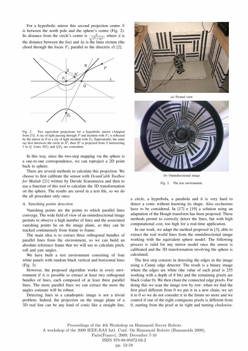
We have built a test environment consisting of fourwhite panels with random black vertical and horizontal lines(Fig. 3).
However, the proposed algorithm works in every envi-ronment if it is possible to extract at least two orthogonalbundles of lines, each composed of at least three parallellines. The more parallel lines we can extract the more theangles estimate will be robust.
Detecting lines in a catadioptric image is not a trivialproblem. Indeed, the projection on the image plane of a3D real line can be any kind of conic like a straight line,
(a) Frontal view
(b) Omnidirectional image
Fig. 3. The test environment.
a circle, a hyperbola, a parabola and it is very hard todetect a conic without knowing its shape. Also occlusionshave to be considered. In [17] e [19] a solution using anadaptation of the Hough transform has been proposed. Thesemethods permit to correctly detect the lines, but with highcomputational cost, too high for a real-time application.
In our work, we adapt the method proposed in [3], able toextract the real world lines from the omnidirectional imageworking with the equivalent sphere model. The followingprocess is valid for any mirror model once the sensor iscalibrated and the 3D transformation involving the sphere iscalculated.
The first step consists in detecting the edges in the imageusing a Canny edge detector. The result is a binary imagewhere the edges are white (the value of each pixel is 255working with a depth of 8 bit) and the remaining pixels areblack (value 0). We then chain the connected edge pixels. Fordoing this we scan the image row by row: when we find thefirst pixel different from 0 we put it in a new chain, we setit to 0 so we do not consider it in the future no more and wecontrol if one of the eight contiguous pixels is different from0, starting from the pixel at its right and turning clockwise.
Proceedings of the 4th Workshop on Humanoid Soccer RobotsA workshop of the 2009 IEEE-RAS Intl. Conf. On Humanoid Robots (Humanoids 2009),
Paris(France), 2009, December 7-10ISBN 978-88-95872-03-2
pp. 52-59

If yes, this new pixel is inserted in the chain and set to0, we control the eight contiguous pixels and so on, untilsome adjacent edgel exists. When the neighbours finish, wecome back to the first pixel of the chain and we repeat thesame operation a second time, so we consider a possiblefork. Further bifurcations will enter in a different chain. SeeFig. 4 for an example.
Fig. 4. An example of the chaining of the connected edgels. The numbersshow the insertion order. Pixels marked with an asterisk are not inserted inthe current chain, even though they are connected to the others.
We delete all the chains with a length shorter thanminPixels. For any valid chain we store the two extremes,that can be the first pixel inserted in the chain (pixel 1in Fig. 4), the last pixel inserted (pixel 13), or the lastpixel inserted before the second propagation (pixel 7). Inthe previous example the extremes are pixel 7 and 13. It hasbeen proved in [7] that the projection of a real world lineonto the sphere is a great circle, has in Fig. 5.
Fig. 5. The projection of a line on the sphere is a great circle (from [11].
Exploiting this property we can infer whether a chaincorresponds to the projection of a world line. We projecteach chain on the sphere using the file that we have savedafter the sensor calibration. Let P1 = (X1, Y1, Z1) and PN =(XN , YN , ZN ) be the two endpoints of a chain composed of
N pixels. These two points define a unique great circle Cthat lie on the plane P passing through the sphere centre O,whose normal is −→n =
−−→OP1 ×
−−−→OPN . For each point Pi of
the circle we calculate its distance from the plane P withthe formula d =
−−→OPi·−→n|−→n | . If the average of the distances of
the chain points from P is smaller than minDist, the wholechain corresponds to the projection of a line in the world andwe identify it with its normal. Otherwise, we split the chaininto two sub-chains at the point of maximum distance fromthe plane and we perform the same control for each of thetwo sub-chains. The splitting step ends when the consideredchain corresponds to a line or the chain length is smaller thanminPixel. In [3], they suggest to use relative high valuesfor both thresholds because the shorter the chain is, the morefragile the estimation of the great circle normal is.
As proved in [7], the great circles corresponding to abundle of parallel lines intersect into two antipodal points onthe sphere. Thus, in order to detect bundles of parallel lineswe use the following algorithm. Let −→n1 and −→n2 the normalsof two great circles on the sphere. Vector −→u passing throughthe intersections I1 and I2 of the two circumferences can becalculated with the cross product −→u = −→n1×−→n2. We computethe same operation for each pair of circle. If at least threelines have the same intersection points, we consider them asa bundle.
It has been proved in [5] that the direction of the vector −→uis the same of that of the bundle of parallel lines associatedto it (Fig. 6). So all the lines in the same bundle arecharacterized to have the same vector −→u .
Fig. 6. The direction of two parallel lines is the same of that of the linepassing through the intersection points of the corresponding circumferences(from [3]).
In our implementation, once we calculate the vanishingpoints of each pair of circumferences, we group them accord-ing to their position using special lists. Every list containsa reference point that is the average point of the elementsinserted in that list. For each vanishing point, we calculatethe distance from the reference point of each list. When wefind a distance lower than a certain threshold, we put it in
Proceedings of the 4th Workshop on Humanoid Soccer RobotsA workshop of the 2009 IEEE-RAS Intl. Conf. On Humanoid Robots (Humanoids 2009),
Paris(France), 2009, December 7-10ISBN 978-88-95872-03-2
pp. 52-59

the corresponding list. If no suitable list exists, we create anew one.
The average point of the list with the greatest number ofelements represents the vector corresponding to the principaldirection. The second direction is determined by the vectororthogonal to it, belonging to the list with the greater numberof elements. For efficiency reasons, the third direction isachieved making the cross product of the other two ones.So, we must detect at least two perpendicular bundles ofparallel lines in the environment. It is possible in this wayto define an orthogonal reference system made up of thesethree axes. An example of the whole procedure is shown inFig. 7.
III. VISUAL GYROSCOPE
The reference frame is not yet completed because we havenot set the axes orientation. To distinguish the vertical axisfrom the horizontal ones, in [5] the authors propose to detectthe sky supposing that it represents the brightest part closeto the omnidirectional image border. We work in an indoorenvironment so we cannot use this approach. We avoid theproblem assuming that the sensor starts to work with therobot in vertical position. Thus, in the first captured framethe software decides that the vertical axis is that, among thethree calculated, at the minimum distance from the verticalvector Z = [0, 0, 1].
To calculate pitch and roll angles it is sufficient to referto this axis (labeled with V ), while the two horizontalaxes will be used in the next paragraph to estimate therotation. Once we fix the initial reference frame, the visualgyroscope starts to calculate the camera slope analyzingeach new captured frame. From every image we extract thethree principal directions. Each new axis will replace thecorresponding one calculated in the previous frame, so wecan track their movements. We do not replace the old axisif the corresponding new one diverge more than a certainangle. We assume that the rotation between two consecutiveframes is always lower than 45◦ for each of the three angles,that is a valid assumption with the high frame rate that weuse.
The angles estimation is not made calculating the axismovement between consecutive frames, because this canlead to a sum of errors, but it is made in an absolute waycomparing the last V vector with the Z axis.
We deduce pitch ψ and roll ρ angles as follows
ψ =yV
|yV |arccos
(|zV |√y2
V + z2V
), (1)
ρ =−xV
|xV |arccos
(|zV |√x2
V + z2V
). (2)
Each new measurement is averaged with the four previousones, so we can obtain more accurate values without highfluctuation from one frame to another.
The angles obtained with the catadioptric sensor have beencompared with those provided by an inertial accelerometer.We can see in the graphic in Fig. 8 that there are no
(a)
(b)
(c)
Fig. 7. Steps for the vanishing points extraction from Fig. 3 (b): (a)detection of the edges and concatenation of the connected pixels, (b)detection of the lines that correspond to straight lines in the real world,(c) computation of the vanishing points corresponding to the three principaldirections of the reference frame.
Proceedings of the 4th Workshop on Humanoid Soccer RobotsA workshop of the 2009 IEEE-RAS Intl. Conf. On Humanoid Robots (Humanoids 2009),
Paris(France), 2009, December 7-10ISBN 978-88-95872-03-2
pp. 52-59

substantial differences between the two measurements. Thisproves the correctness of the designed visual gyroscope.
Fig. 8. Comparison between the pitch angle calculated by an inertialaccelerometer and that calculated by the visual gyroscope.
A. Visual compass
The most used technique to calculate the rotation consistsin tracking some particular points with RANSAC so that wecan estimate the rotation angle between consecutive frames,working with omnidirectional [9] or unwarped images [12][16], or using the optical flow like in [8] and [15].
In our work instead, we try to see if the simple vanishingpoints method is also valid in this scope. To build the visualcompass we use the two horizontal axes of the referenceframe, labeled with R1 e R2. It is not important which ofthese two axes is the first and which is the second, we areonly interested to distinguish them so we can track theirmovements. The robot rotation will be calculated relativelyto their start position. As seen before, we extract the new axesR′1 and R′2 from each frame. They will replace the previousones only if the difference angle is less than a certainquantity. The rotation angle is always estimated between theinitial and the last axis. In this case, the provided informationis duplicated because we only need one horizontal axis tocalculate the yaw angle. Knowing two horizontal axes wecan apply a control method. Indeed what one can expect isthat the angle given by R1 is the same given by R2. So, ifthe difference between the two angles is less than a certainangle we compute their average, otherwise one of the twovanishing points is wrong and we consider only the anglenearer to the corresponding one calculated in the previousframe. The results are good enough if the movements of therobot are on the XY plane.
B. Results in real environments
The proposed algorithm has been tested also in environ-ments different from the test one of Fig. 3. It continues towork if it is possible to extract some parallel lines. As wecan see in the following two examples, we are able to extractall the possible lines from the image. In Fig. 9 we place therobot in a RoboCup environment. All the field lines and thegoalposts have been extracted and they can be used to definea three axes reference frame. In Fig. 10 instead, the robot
is set on a desk in our laboratory. As we can see, this kindof environment contains several objects that define a lot oflines. Unfortunately, most of these lines are too short andrepresent only noise for the visual gyroscope. So we discardall the lines shorter than a certain length and preserve onlythe longest lines. Even if the number of detected lines issmall, it is sufficient to estimate attitude and heading anglescorrectly, but we have to consider that the noise increases ifthe lines extracted are shorter.
The computation time is suitable for a real-time appli-cation since the algorithm in our C++ implementation canprocess about 20 frame per second.
IV. BODY STABILIZATION
We have seen how to extract the vanishing points ofparallel lines from the environment and use them to estimatethe slope and the rotation of the catadioptric sensor. Wemount the sensor in place of the head of our robot. Since thecamera is stuck to the robot, the calculated angles correspondof the slope of the robot trunk. In this way we can use thisinformation to stabilize the robot during the walk withoutusing any inertial sensor. It is interesting to notice that we donot stabilize only the robot’s posture but also the perception.Indeed, since the robot always tries to keep its trunk invertical position, camera oscillations are reduced and thisis a great benefit for all the vision algorithms that we useduring the robot walk, such as tracking and blob recognition.
A. Stabilization of the vertical position
In the first test the robot had to keep the vertical positioncorrecting its pitch and roll angles when standing still. Todo this, we correct the four servomotors of the ankles,compensating them with a quantity equal to the oppositeof the angle measured in the two directions. We performedtwo experiments. In the first one, when the robot is pushedforward or backward, it puts up resistance rising on the tiptoes or on its heels (in Fig. 11 (a) the robot is reactingto a backward push) to maintain its vertical posture. Thesame if the push is lateral. In the second experiment therobot stands on a platform which changes its inclinationand it is able to modify its position in real time keepingit upright. In Fig. 11 (b) the robot is on an inclined plane inthe position corresponding to the upright posture as it wason a horizontal surface. In Fig. 11 (c) instead we can noticehow the compensation applied to the ankles brings the robotback to the vertical position.
B. Walking with stabilization
Many articles show how to stabilize a humanoid robotgait modifying the motor positions in order to maintainthe Zero Moment Point inside the convex hull of the foot-support area [14]. Most of the time, walking gaits are learntin simulation simplifying the robot model as one or twomasses inverted pendulum model [13]. To pass to the realrobot it is necessary an exhaustive study to establish theweight distribution and the movements of each servomotor.The simple model used in simulation must be converted to
Proceedings of the 4th Workshop on Humanoid Soccer RobotsA workshop of the 2009 IEEE-RAS Intl. Conf. On Humanoid Robots (Humanoids 2009),
Paris(France), 2009, December 7-10ISBN 978-88-95872-03-2
pp. 52-59

Fig. 9. Vanishing points detection in a RoboCup environment. Fig. 10. Vanishing points detection in a lab environment.
Proceedings of the 4th Workshop on Humanoid Soccer RobotsA workshop of the 2009 IEEE-RAS Intl. Conf. On Humanoid Robots (Humanoids 2009),
Paris(France), 2009, December 7-10ISBN 978-88-95872-03-2
pp. 52-59

(a) The robot reacts to a back-ward push rising on the tip toes
(b) The robot on the inclinedplane without any correction
(c) The robot on the inclinedplane with ankle correction
Fig. 11. Posture correction using the visual gyroscope.
adapt it to the real robot, considering that complexity growswhen the degrees of freedom increase.
We chose a different approach, as suggested in [1] and[10]. The idea is to create an offline walk pattern, fixminimum and maximum thresholds on the inclination thatthe robot can achieve during the walk and when the visualgyroscope detects an out of range value modify the robotwalking gait to recover balance. One can choose to straightenup the robot, to lower its centre of mass, to slow down itsmovements or to stop them until it recovers its balance, orto put it in a safe position that minimize the damages in caseof fall.
We have designed a static walk pattern made up of fourelementary movements. We have made several experimentsto measure the range of pitch and roll angles for eachmovement, using our visual gyroscope.
It is interesting to note the periodicity of the graphs of thetwo angles measured during the walk (Fig. 12). Analyzingthese graphs, it is possible to realize if there is any phase ofthe walk in which there are anomalous oscillations and inthis way correct the position of the motors.
At the moment we do not consider the roll angle becausemodifying the robot gait with a lateral stabilization requiresmore deep studies. Indeed in this situation we need to modifyall the servos of both legs to ensure the right support in everyphase of the walk. What we do is to use the pitch angle tocontrol frontal inclination.
During the walk, for each of the four elementary move-ments we control if the pitch angle is inside the fixed rangeof values. If not, we change the two ankle motors responsiblefor the frontal slope, compensating them with an angle
(a) Pitch angle
(b) Roll angle
Fig. 12. Pitch and roll angles measured during the walk.
equal to the opposite of the difference between the currentvalue and the nearest threshold. The same compensation isapplied to the other three elementary movements. Applyinga stabilization to a static walk allow to obtain a more fluidand balanced gait. The most evident results can be noticed onan inclined plane, on which the robot walks with a verticalposition and it is able to modify its posture online when theterrain changes its slope (Fig. 13).
Fig. 13. Four steps of the walk. The gait above is without stabilization,while we apply stabilization in the gait below.
Two videos are available at the following links:http://www.youtube.com/watch?v=PfuQ0VHrz1ohttp://www.youtube.com/watch?v=H2YCr9quJuk
Proceedings of the 4th Workshop on Humanoid Soccer RobotsA workshop of the 2009 IEEE-RAS Intl. Conf. On Humanoid Robots (Humanoids 2009),
Paris(France), 2009, December 7-10ISBN 978-88-95872-03-2
pp. 52-59

V. CONCLUSIONS AND FUTURE WORKS
We have presented a simplify method to use the catadiop-tric sensor as a visual gyroscope and a visual compass.
We have performed experiments in three different envi-ronments to show that we can extract a suitable number ofparallel lines to determine the vanishing points of the threeprincipal orthogonal directions.
The designed stabilization system, even though it is verysimple, allows to observe some improvements, consisting ina better balance and in the capacity to maintain the verticalposition independently of the terrain slope.
The next step is to improve the system allowing a morecomplex stabilization to take account of also the lateralinclination.
VI. ACKNOWLEDGMENTS
The authors would like to thank Stefano Ghidoni for hisadvice and his review work.
REFERENCES
[1] J. Baltes, S. McGrath, J. Anderson, Active Balancing Using Gyro-scopes for a Small Humanoid Robot. Second International Conferenceon Autonomous Robots and Agents (ICARA), pag. 470-475, Decem-ber 13-15, 2004, Palmerston North, New Zealand.
[2] J. P. Barreto, H. Araujo, Geometric Properties of Central CatadioptricLine Images and Their Application in Calibration. In “IEEE Trans-actions on Pattern Analysis and Machine Intelligence”, Volume 27,Issue 8, pag. 1327-1333, August 2005.
[3] J. C. Bazin, I. Kweon, C. Demonceaux, P. Vasseur, Rectangle Extrac-tion in Catadioptric Images. IEEE 11th International Conference onComputer Vision, pag. 1-7, 2007.
[4] J. C. Bazin, I. Kweon, C. Demonceaux, P. Vasseur, UAV Attitude Esti-mation by Vanishing Points in Catadioptric Images. IEEE InternationalConference on Robotics and Automation, Pasadena, CA, USA, May19-23, 2008.
[5] C. Demonceaux, P. Vasseur, C. Pegard, UAV Attitude Computationby Omnidirectional Vision in Urban Environment. IEEE InternationalConference on Robotics and Automation, Roma, Italy, 10-14 April2007.
[6] C. Demonceaux, P. Vasseur, C. Pegard, Robust Attitude Estimationwith Catadioptric Vision. Proceedings of the 2006 IEEE/RSJ Interna-tional Conference on Intelligent Robots and Systems, pag. 3448-3453,October 9-15, 2006, Beijing, China.
[7] C. Geyer, K. Daniilidis, Catadioptric Projective Geometry. Interna-tional Journal of Computer Vision, Volume 45, Issue 3, pag. 223-243,2001.
[8] J. Gluckman, S. K. Nayar, Ego-Motion and Omnidirectional Cameras.In Proceedings of the Sixth International Conference on ComputerVision, pag. 999-1005, 1998.
[9] G. L. Mariottini, S. Scheggi, F. Morbidi, D. Prattichizzo, A RobustUncalibrated Visual Compass Algorithm from Paracatadioptric LineImages. In First Workshop on Omnidirectional Robot Vision, LectureNotes in Computer Science, Springer-Verlag, 2009.
[10] S. McGrath, J. Baltes, J. Anderson, Active Balancing Reflexes forSmall Humanoid Robots. In Proceedings of the 17th IFAC WorldCongress, Volume 17, Part 1, July 6-11, 2008, Seoul, Korea.
[11] C. Mei, E. Malis, Fast Central Catadioptric Line Extraction, Estima-tion, Tracking and Structure from Motion. In Proceedings of the 2006IEEE/RSJ International Conference on Intelligent Robots and Systems,pag. 4774-4779, October 9-15, 2006, Beijing, China.
[12] I. F. Mondragon, P. Campoy, C. Martinez, M. Olivares, Omnidirec-tional Vision applied to Unmanned Aerial Vehicles UAVs Attitude andHeading Estimation. Preprint submitted to Robotics and AutonomousSystems, February 27, 2009.
[13] Napoleon, S. Nakaura, M. Sampei, Balance Control Analysis ofHumanoid Robot based on ZMP Feedback Control. In Proceedingsof the 2002 IEEE/RSJ International Conference on Intelligent Robotsand Systems, pag. 2437- 2442, Volume 3, October 2002, Lausanne,Switzerland.
[14] V. Prahlad, G. Dip, C. Meng-Hwee, Disturbance Rejection by OnlineZMP Compensation. In Robotica (2008), Volume 26, pag. 9-17.Cambridge University Press, United Kingdom.
[15] O. Shakernia, R. Vidal, S. Sastry, Omnidirectional Egomotion Estima-tion From Back-projection Flow. In “CVPRW Computer Vision andPattern Recognition Workshop”, volume 7, pag. 82. June 2003.
[16] I. Stratmann, Omnidirectional Optical Flow and Visual Motion De-tection for Autonomous Robot Navigation. PhD Thesis, UniversitatOsnabruck. October 2007.
[17] P. Vasseur, E. M. Mouaddib, Central Catadioptric Line Detection.In Fifteenth British Machine Vision Conference (BMVC), KingstonUniversity, London, September 7-9, 2004.
[18] J. A. Walraven, Failure Mechanisms in MEMS, Internantional TestConference, pag. 828-833, 2003.
[19] X. Ying, Z. Hu, Catadioptric Line Features Detection using HoughTransform. In Proc. of International Conference on Pattern Recognition(ICPR04), Cambridge, United Kingdom, pp. 839-842, 2004.
[20] Kondo Kagaku Co. URL: http://www.kondo-robot.com/[21] oCamCalib, tutorial e download.
http://asl.epfl.ch/∼scaramuz/research/Davide Scaramuzza files/Research/OcamCalib Tutorial.htm
Proceedings of the 4th Workshop on Humanoid Soccer RobotsA workshop of the 2009 IEEE-RAS Intl. Conf. On Humanoid Robots (Humanoids 2009),
Paris(France), 2009, December 7-10ISBN 978-88-95872-03-2
pp. 52-59


![Footstep adaptation strategy for reactive omnidirectional walking in humanoid robots … · 2020. 4. 2. · Footstep adaptation strategy 59 new model first appeared in ref. [12];](https://static.fdocuments.net/doc/165x107/6009e01be72c367ace359d3b/footstep-adaptation-strategy-for-reactive-omnidirectional-walking-in-humanoid-robots.jpg)