
Human-Guided Surgical Robot System for Spinal Fusion ... Surgical Robot System for Spinal ... CoRASS...
7
DO NOT COPY Human-Guided Surgical Robot System for Spinal Fusion Surgery: CoRASS Jongwon Lee, Keehoon Kim, Wan Kyun Chung, Seungmoon Choi and Young Soo Kim Abstract— There are two main limitations in the conventional robot-assisted spinal fusion surgery. Since the end effector in the state of art has a role of guiding the insertion pose of a screw only, i) convenience that can be obtained when the robot intervenes in the surgery more actively could be limited. ii) The insertion pose of a screw provided by the robots could be deteriorated by surgeon’s resisting force since he should insert a screw with his own hand withstanding the large reaction force transmitted through the drilling handle. To overcome those limitations, this paper proposes a novel approach for spinal fusion, wherein the robot performs the spinal fusion using the equipped end effector following surgeon’s guide. We developed a dexterous small-sized the end effector that can perform previous gimleting and screwing tasks into the vertebrae. A five-DOF robot body that has kinematically-closed structure guides the insertion pose of a screw and resists strong reaction force firmly during the screwing process. Based on admittance control framework, the surgeon controls the pose of the end effector precisely to compensate induced static/dynamic errors during the operation. A torque feedback method without torque sensor that suggests the haptic information about the status of drilling is also included. The performance of the CoRASS was verified by experiments. I. INTRODUCTION The herniated disc occurs when the disc is damaged by sudden strain on the back or degeneration from aging. When the disc is damaged, the center of the disc squeezes out through a weak point in the fibrous out-layer. Since this bulge often presses on nerves, the patient feels the back pain or sciatica [1]. The spinal fusion surgery is one of the treatments that requires extreme caution among various treatments of disc illness. However, in many cases, it was demonstrated that convalescence after spinal fusion is most favorable when we compared it with that of other surgical treatments such as endoscope surgery or microscope surgery, once the operation is successfully performed. Fig.1 shows fluoroscopic images of two unstable vertebrae that were successfully “fused” after spinal fusion. Screws are inserted into the vertebrae, and fixed together by connecting rods. It can restrict relative motions between two vertebrae, so, the pain can be cured. The procedures of conventional surgeon-operated spinal fusion follows 1) preoperative plan- ning using MRI and/or CT scan images, 2) skin incision, 3) Jongwon Lee and Wan Kyun Chung are with the Robotics Laboratory at POSTECH, KOREA {samjong2, wkchung}@postech.ac.kr Keehoon Kim is with the Laboratory for Intelligent Mechanical Systems, Northwestern Univ., USA [email protected] Seoungmoon Choi is with the Haptics and Virtual Reality Laboratory at POSTECH, KOREA [email protected] Young Soo Kim is with the Center for Intelligent Surgery Sys- tem, School of Medicine, Hanyang University, KOREA ksy8498 @hanyang.ac.kr dilation of an aperture using K-wire and dilators 4) gimleting the cortical layer (protective outer shell) with a hammer, 5) insertion of screws into the vertebrae, 6) interlocking using connecting rods and 7) suturing the wound. In this procedure, the main difficulty is the surgeon’s lim- ited manipulation capability needed to maintain the accurate insertion pose of screws. Surgeons should insert a screw with the diameter of 3 or 4mm into the pedicle of the vertebra that has the diameter of 6mm. If the surgeon fails to control the insertion direction of a screw by mistake, the screw can touch the spinal cord. It can cause serious injuries to the patient. In the real operation, screw misplacement occurs in the ratio of 10%. And half of them affects as critical injuries to patients [2] [3]. In order to improve the limitations of the present spinal fusion surgery, many robotic surgical systems have been developed. A focus has been on complementing surgeon’s limited capabilities of precisely controlling the insertion pose of a screw with the robot manipulator. Santos-Munn et al. introduced a surgeon helper robot that integrated the C- arm fluoroscope with the industrial PUMA-560 manipulator, wherein the robot guides the insertion pose of a screw during spinal fusion [4]. However, it is somewhat inconvenient to surgeons since determination of insertion angles (transverse angle and sagittal angle) are divided in pre-operative and intra-operative step, individually. Cleary et al. also developed guiding-assist robot based on minimally invasive surgery (MIS) paradigm. They integrated MRI, a 3-D reconstruc- tion algorithm, an optical tracking system and a serial-type manipulator to guide the insertion pose of a screw during screwing [5]. Since they used the mobile CT as an intra- operative imaging device instead of fluoroscope, the intra- operative planning that determines the insertion angles can be done more accurately and conveniently. Shoham et al. devel- Fig. 1. Fluoroscopic images of two vertebrae fused by spinal fusion. 2008 IEEE International Conference on Robotics and Automation Pasadena, CA, USA, May 19-23, 2008 978-1-4244-1647-9/08/$25.00 ©2008 IEEE. 3881 Authorized licensed use limited to: Northwestern University. Downloaded on December 22, 2008 at 22:38 from IEEE Xplore. Restrictions apply.
Transcript of Human-Guided Surgical Robot System for Spinal Fusion ... Surgical Robot System for Spinal ... CoRASS...

DO NOT COPY
Human-Guided Surgical Robot System for Spinal Fusion Surgery:CoRASS
Jongwon Lee, Keehoon Kim, Wan Kyun Chung, Seungmoon Choi and Young Soo Kim
Abstract— There are two main limitations in the conventionalrobot-assisted spinal fusion surgery. Since the end effector inthe state of art has a role of guiding the insertion pose of ascrew only, i) convenience that can be obtained when the robotintervenes in the surgery more actively could be limited. ii)The insertion pose of a screw provided by the robots could bedeteriorated by surgeon’s resisting force since he should inserta screw with his own hand withstanding the large reaction forcetransmitted through the drilling handle. To overcome thoselimitations, this paper proposes a novel approach for spinalfusion, wherein the robot performs the spinal fusion using theequipped end effector following surgeon’s guide. We developeda dexterous small-sized the end effector that can performprevious gimleting and screwing tasks into the vertebrae. Afive-DOF robot body that has kinematically-closed structureguides the insertion pose of a screw and resists strong reactionforce firmly during the screwing process. Based on admittancecontrol framework, the surgeon controls the pose of the endeffector precisely to compensate induced static/dynamic errorsduring the operation. A torque feedback method without torquesensor that suggests the haptic information about the status ofdrilling is also included. The performance of the CoRASS wasverified by experiments.
I. INTRODUCTION
The herniated disc occurs when the disc is damaged bysudden strain on the back or degeneration from aging. Whenthe disc is damaged, the center of the disc squeezes outthrough a weak point in the fibrous out-layer. Since this bulgeoften presses on nerves, the patient feels the back pain orsciatica [1]. The spinal fusion surgery is one of the treatmentsthat requires extreme caution among various treatments ofdisc illness. However, in many cases, it was demonstratedthat convalescence after spinal fusion is most favorable whenwe compared it with that of other surgical treatments such asendoscope surgery or microscope surgery, once the operationis successfully performed.
Fig.1 shows fluoroscopic images of two unstable vertebraethat were successfully “fused” after spinal fusion. Screws areinserted into the vertebrae, and fixed together by connectingrods. It can restrict relative motions between two vertebrae,so, the pain can be cured. The procedures of conventionalsurgeon-operated spinal fusion follows 1) preoperative plan-ning using MRI and/or CT scan images, 2) skin incision, 3)
Jongwon Lee and Wan Kyun Chung are with the Robotics Laboratory atPOSTECH, KOREA {samjong2, wkchung}@postech.ac.kr
Keehoon Kim is with the Laboratory for Intelligent Mechanical Systems,Northwestern Univ., USA [email protected]
Seoungmoon Choi is with the Haptics and Virtual Reality Laboratory atPOSTECH, KOREA [email protected]
Young Soo Kim is with the Center for Intelligent Surgery Sys-tem, School of Medicine, Hanyang University, KOREA [email protected]
dilation of an aperture using K-wire and dilators 4) gimletingthe cortical layer (protective outer shell) with a hammer, 5)insertion of screws into the vertebrae, 6) interlocking usingconnecting rods and 7) suturing the wound.
In this procedure, the main difficulty is the surgeon’s lim-ited manipulation capability needed to maintain the accurateinsertion pose of screws. Surgeons should insert a screw withthe diameter of 3 or 4mm into the pedicle of the vertebrathat has the diameter of 6mm. If the surgeon fails to controlthe insertion direction of a screw by mistake, the screw cantouch the spinal cord. It can cause serious injuries to thepatient. In the real operation, screw misplacement occurs inthe ratio of 10%. And half of them affects as critical injuriesto patients [2] [3].
In order to improve the limitations of the present spinalfusion surgery, many robotic surgical systems have beendeveloped. A focus has been on complementing surgeon’slimited capabilities of precisely controlling the insertion poseof a screw with the robot manipulator. Santos-Munn et al.introduced a surgeon helper robot that integrated the C-arm fluoroscope with the industrial PUMA-560 manipulator,wherein the robot guides the insertion pose of a screw duringspinal fusion [4]. However, it is somewhat inconvenient tosurgeons since determination of insertion angles (transverseangle and sagittal angle) are divided in pre-operative andintra-operative step, individually. Cleary et al. also developedguiding-assist robot based on minimally invasive surgery(MIS) paradigm. They integrated MRI, a 3-D reconstruc-tion algorithm, an optical tracking system and a serial-typemanipulator to guide the insertion pose of a screw duringscrewing [5]. Since they used the mobile CT as an intra-operative imaging device instead of fluoroscope, the intra-operative planning that determines the insertion angles can bedone more accurately and conveniently. Shoham et al. devel-
Fig. 1. Fluoroscopic images of two vertebrae fused by spinal fusion.
2008 IEEE International Conference onRobotics and AutomationPasadena, CA, USA, May 19-23, 2008
978-1-4244-1647-9/08/$25.00 ©2008 IEEE. 3881
Authorized licensed use limited to: Northwestern University. Downloaded on December 22, 2008 at 22:38 from IEEE Xplore. Restrictions apply.

DO NOT COPY
oped a parallel-type miniature bone mounted robot (MARS)to accurately position surgical tools [6] [7]. Since the robotis mounted on the patient’s vertebrae, a tracking system forcompensating patient’s movement (e.g., respiratory motions)is not necessary. However, due to relatively large incision,the patient’s recovery time is longer than that of the MISsystem. Chung et al. also developed a serial-type manipulator(SPINEBOT) for the same purpose [8] [9]. Since it supportsMIS scheme, the trauma and recovery time to the patientcould be reduced. In conclusion, these robotic systems havecommon characteristics that they are surgeon helper robots toprovide the desired insertion pose of a screw to a surgeon, so,they can suggest a solution to rectify the predefined difficultyof the conventional surgeon-operated spinal fusion surgery.
However, there are two main limitations in the conven-tional robot-assisted spinal fusion surgery. 1) Conveniencethat can be obtained when the robot intervenes in the surgerymore actively could be limited since the end effector inthe state of art for spinal fusion has a role of guiding theinsertion pose of a screw only. 2) Since conventional robotsystems provide a fixture only for guiding the desired pose ofa screw, the surgeon himself should insert the screw into thebone with his own hand withstanding the large reaction forcetransmitted through the drilling handle. In this procedure, theinsertion direction of a screw provided by the robot couldbe deteriorated by surgeon’s resisting force during screwing,resulting in small gap between the bone and the insertedscrew. As time goes, this gap extends, so, re-operation isneeded to replace the screw with the larger ones.
These two limitations can be solved when the robotintervenes in the surgery more actively. If screw insertioncan be performed by the end effector of the robot, surgeon’slaborious screwing that leads to inaccurate operation resultsdoes not be required anymore. Moreover, we can alwaysmake the insertion pose of a screw provided by the robotidentical to that of the preplanned path since the surgeondoes not need to apply the resisting force to the robot.
Then, to use the end effector that can perform the spinalfusion surgery, what should be considered? First, the robotshould be able to move the pose of the end effector preciselywithstanding large reaction force/torque occurring in thesurgery. The force and torque needed to complete gimletingand screwing tasks in spinal fusion are about 1200N and3.2Nm, respectively in [10]. Since these values are aboutone hundred times larger than those of cardiac operation,if a surgeon performs the spinal fusion with the robot thathas kinematically-open structure (e.g., da Vinci by InstitutiveSurgical or SPINEBOT by Hanyang Univ.), the systemcannot bear the gimleting force and insertion torque. Second,the mechanisms to compensate induced static/dynamic errorsduring the operation should be considered. If the robotsystem cannot compensate such errors (e.g., the registrationand manufacturing errors and deviations of the actual poseinduced by the strong reaction force between the vertebraeand the tools), the end effector might insert a screw withthe wrong pose. Third, a master/slave drilling system and atorque feedback algorithm for screwing should be incorpo-
Fig. 2. Overall structure of the CoRASS.
rated. Since screw insertion is a very delicate and cautiousprocedure, the screwing task performed by the end effectorshould be progressed under the surgeon’s supervision. Byusing the master/slave drilling system, surgeon’s expertisecan be exploited during screwing. To suggest the status ofa screw to the surgeon, a torque feedback method is alsorequired.
In this paper, to accomplish the goals, we proposed acooperative robot-assisted surgery system (CoRASS) forspinal fusion as shown in Fig.2. As implied in its name, theCoRASS is the surgical robot, featuring with a dexteroussmall-sized end effector that can perform previous gimletingand screwing tasks with greater accuracy, a rigid six-DOFrobot that has kinematically-closed structure specialized tospinal fusion, cooperative manipulation framework that aug-ments surgeon’s judgment and sensory integration into theoperation for compensating the mentioned errors, mechan-ically decoupled master/slave drilling system in the endeffector for improved safety during screwing, and a torquefeedback method for suggesting the status of a screw tothe surgeon. Integrating CoRASS with a surgery navigationsystem is in progress. The characteristics and performanceof the navigation system are described in [11].
This paper is organized as follows. The design andfunctionality of the end-effector is described in details inSection II. Section III presents five-DOF robot body that haskinematically-closed structure, along with the measurementof its dynamic tracking errors. The control schemes forthe cooperative position control and the torque feedbackmethod during the screwing process is elaborated in SectionIV. The performance of the CoRASS is evaluated throughexperiments in Section V, followed by conclusions in SectionVI.
II. END EFFECTOR OF CORASS
Since the capability of the robot depends on the functionof the end effector, the end effector design is one of themost important considerations during the robot system de-velopment. The goal of the design is to make a dexterous endeffector which can perform the conventional gimleting and
3882
Authorized licensed use limited to: Northwestern University. Downloaded on December 22, 2008 at 22:38 from IEEE Xplore. Restrictions apply.
DO NOT COPY(a)
(b)
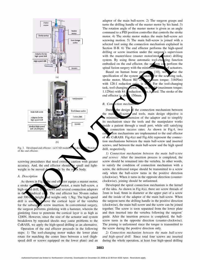
Fig. 3. Developed end effector : (a) CAD model of the design (b) Prototypeof the end effector.
screwing procedures that need extreme caution with greateraccuracy. And, the end effector should be small and light-weight to be moved dexterously by the robot body.
A. Description
As shown in Fig.3, the end effector equips a master motor,a stroke motor, a tool-changing motor, a main ball-screw, ahigh-speed drill, four screws and several connection adaptorsin the cylindrical case. The end effector has 50-mm radiusand 300-mm height, and weighs only 1.5kg. The high-speeddrill is used to remove the cortical layer of the vertebrafor the subsequent screw insertion. In conventional surgery,the surgeon performs gimleting with a hammer, wherein thegimleting force to penetrate the cortical layer is as high as1200N. However, since the size of the actuator and systembreakdown by repeated shocks may cause problems to theCoRASS, we apply the high-speed drilling as an alternative.
Operation of the end effector proceeds in the followingsteps: 1) The tool-changing motor makes the lower platerotate for matching the center lines between a tool (high-speed drill or screws equipped on the lower plate) and an
adaptor of the main ball-screw. 2) The surgeon grasps andturns the drilling handle of the master motor by his hand. 3)The rotation angle of the master motor is given as an anglecommand to a PID position controller that controls the strokemotor. 4) The stroke motor makes the main ball-screw actscrewing motion. 5) The main ball-screw is joined with aselected tool using the connection mechanism explained inSection II-B. 6) The end effector performs the high-speeddrilling or screw insertion under the surgeon’s supervisionwith the master/slave (master motor/stroke motor) drillingsystem. By using those automatic tool-changing functionembodied on the end effector, the surgeon can perform thespinal fusion surgery with the minimum number of actuators.
Based on human bone properties [10], we choose thespecification of the system actuators. For the screwing task,stroke motor, Maxon RE 25 (maximum torque; 3.84Nm)with 128:1 reduction ratio, is used. For the tool-changingtask, tool-changing motor, Maxon EC 16 (maximum torque;1.12Nm) with 84:1 reduction ratio, is used. The stroke of theend effector is about 150mm.
B. Connection mechanisms
During the design of the connection mechanism betweenthe main ball-screw and tools, main design objective isto minimize the dimension of the adaptor and to simplifyits mechanism since the tools and the manipulator worksinside a patient through a small port, while still satisfyinghigh connection success rates. As shown in Fig.4, twoconnection mechanisms are implemented to the end effectorof the CoRASS. Fig.4(a) and Fig.4(b) represent the connec-tion mechanisms between the main ball-screw and insertedscrews, and between the main ball-screw and the high speeddrill, respectively.
1) Connection mechanism between the main ball-screwand screws: After the insertion process is completed, thescrew should be remained into the vertebra. In other words,to satisfy the condition of connection mechanism with ascrew, the delivered torque should be transmitted to a screwonly when the ball-screw turns in the positive direction(clockwise). When it turns in the opposite direction (counter-clockwise), joining should be unfastened.
Developed the spiral connection mechanism is the kernelof the idea. As shown in Fig.4(a), there are screw threads of2mm in lead, 8mm in diameter at the upper part of a screwand the inside of the adaptor of the main ball-screw. Whenthe surgeon turns the drilling handle in the positive direction(clockwise), the main ball-screw and the screw can be joinedtogether. The screw is soon separated from the lower plateand then inserted into the vertebra following the surgeon’guide. After the insertion process is completed, the ball-screw turns in the opposite direction (counter-clockwise).The joining is unfastened since the torque is transmitted tothe screw during the positive direction only.
2) Connection mechanism between the main ball-screwand high-speed drill: Since total four screws are insertedduring the whole operation, at least four high-speed drilling
3883
Authorized licensed use limited to: Northwestern University. Downloaded on December 22, 2008 at 22:38 from IEEE Xplore. Restrictions apply.

DO NOT COPY
(a)
(b)
Fig. 4. Connection mechanisms between the main ball-screw and surgicaltools: (a) Joining between the main ball-screw and a screw (b) Joiningbetween the main ball-screw and a high-speed drill.
processes are needed to complete the spinal fusion. The high-speed drill should be carried back to its original place for thenext use. We apply one-touch joining mechanism utilizingthe elasticity of a metal C-clip. As shown in Fig.4(b), thediameter of the C-clip is slightly lager than the internaldiameter of the adaptor opening of the high-speed drill. Theclip is relaxed at the inside of the adaptor, once the clipis inserted. It induces the joining force as large as 18Nbetween main ball-screw and high speed drill. However, inorder to insert the C-clip into the adaptor, same amountof attraction force is also required during joining process.An electromagnet and shock absorber equipped in the lowerplate generate the attraction force of 45N between the adaptorand the ball-screw. Asymmetric shape of the adapter alsomakes the disparity of the interaction force between theattaching and detaching step. The connection success ratereaches about 98%.
III. ROBOT BODY OF CORASS
In section II, we discussed the design of the dexteroussmall-sized end effector that can perform existing gimletingand screwing tasks. Then, the remained objective of a robotsystem is to align the end effector at a preplanned positionwith specified orientation accurately. However, since the taskis to manage the vertebrae, the strong reaction force as highas 200N imposed to the robot system makes their joints belifted during screw insertion. We thus designed the robotbody to be inherently stiff in kinematically-closed structure.
A. Description
As shown in Fig.5, the CoRASS has kinematically-closedstructure that has six-DOF motion space including the stroke
(a)
(b)
Fig. 5. Robot body of CoRASS: (a) CAD model (b) Prototype.
motion of the end effector. To provide the accurate desiredinsertion pose of a screw, the robot should have at least five-DOFs, i.e., three translation (XYZ) and two rotation axes(Rx, Ry). Ball-screws and linear motion guides are usedto transform the rotational motion into the linear motion.Maxon EC 45 motor (maximum torque; 1.52Nm) with 18:1 reduction ratio is used in each translation part. For therotational motion, Maxon EC 45 (maximum torque; 8.45Nm)and harmonic drive with 100:1 reduction ratio are used. Sinceneeded workspace of the end tip to complete the spinalfusion is about 50×50×50mm3, the CoRASS is designedto provide 100×100×70mm3 workspace considering theinsertion angles of a screw.
B. Performance Test of the CoRASS
Each joint is controlled by a PID position controllerthat has 1kHz update rate. Dynamic tracking errors weremeasured for each joint of the CoRASS. Given sinusoidaltrajectory in the three translation joints is shown in Fig.6(a).Similar data for the two revolute joints is shown in Fig. 6(c).Fig.6(b)6(d) show the tracking errors in the translation andorientation parts, respectively. Tracking errors are boundedbelow 0.1mm and 1.0◦. Static errors of the CoRASS werealso measured to be bounded below 0.5µm for translationand 0.05◦ for rotation.
IV. CONTROL ARCHITECTURE OF CORASS
A. Position Control
To increase the accuracy of the operation, the robot systemshould be able to insert a screw at the preplanned positionand orientation precisely. However, no matter how we reduce
3884
Authorized licensed use limited to: Northwestern University. Downloaded on December 22, 2008 at 22:38 from IEEE Xplore. Restrictions apply.

DO NOT COPY
(a)
(b)
(c)
(d)
Fig. 6. Measure dynamic tracking errors: (a) Desired trajectory intranslation parts (b) Tracking errors in translation X,Y,Z-axes (c) Desiredtrajectory in rotation parts (d) Tracking errors in Rotation X,Y-axes.
the tracking errors using the controller, system errors likeregistration errors and manufacturing errors cause inaccurateoperation results. And, the pose of vertebrae is slightlychanged during screwing since the strong reaction force isimposed the vertebrae. If these deviations can be detectedusing other intra-operative imaging devices like fluoroscope,mentioned problems can be easily solved. However, it is noteasy to estimate such delicate errors quantitatively using the2-D binary images obtained by fluoroscope.
To solve those problems, we apply the cooperative ma-nipulation paradigm in spinal fusion. A practical use of thecooperative manipulation in the surgical robot was firstlyintroduced at the micro-surgical manipulation system for eyesurgery in [12]. Cooperative manipulation means that therobot moves simultaneously with the operator’s hand, whilesensing forces exerted by the operator on the tool. Althoughthe measurement of the delicate errors is difficult to obtain, it
Fig. 7. Enlarged upper part of the end-effector
(a)
(b)
Fig. 8. System diagram for CoRASS: (a) Block diagram for admittancecontrol (b) Block diagram for torque feedback in the CoRASS.
might be easier to make compensate such errors with the helpof surgeon’s abundant experience and intuition. Cooperativemanipulation can increase the flexibility for controlling theprecise surgical manipulation when the desired insertion poseof a screw needs to be slightly changed due to the systemerrors and/or strong reaction force during the operation.
A 6-axis F/T sensor (ATI; Nano-17) was used to augmentsurgeon’s force commands to the pose of the robot in thefive-DOF motion space. As shown in Fig.7, the F/T sensor ismounted on the top of the end effector. Fig.8(a) represents theadmittance control diagram for the cooperative manipulation.The parameters of the virtual mass-damper model weredetermined to satisfy the system stability. In the figure,Fh and Fp represent the surgeon’s force command and theresponse force due to the end-effector dynamics, respectively.pds is the desired pose of the end effector, whereas pe is theactual. Ps is the robot plant, Zh is the impedance of thesurgeon, and Ks is a control gain.
B. Torque feedback method without torque sensor
Since screw insertion is a very delicate and cautiousprocedure, the screwing task performed by the CoRASSshould be progressed under the surgeon’s supervision. Byusing the master/slave drilling system, surgeon’s expertisecan be exploited during screwing. However, in the realoperation, a friction between the vertebra and the screw
3885
Authorized licensed use limited to: Northwestern University. Downloaded on December 22, 2008 at 22:38 from IEEE Xplore. Restrictions apply.

DO NOT COPY
makes a tactile feedback on surgeon’s drilling hand. Thishaptic information suggests the status of a screw to thesurgeon, e.g. insertion depth, the surgeon thus can make moreaccurate decision that is helpful to increase the safety of thepatient.
In our master/slave drilling system, we should generatethe haptic information identical to that of real operation andtransmit it to master motor of the robot. In our previous work,we introduced the current monitoring method to calculatedrilling torque without torque sensor in [10]. The idea is touse the current signal of the amplifier since the monitoringcurrent is proportional to the load at the motor. The currentmonitoring signal is well matched with the real torque inlow frequency region. This method is also incorporated inthe CoRASS. Using an additional torque sensor at the strokemotor is an alternative, but it is costly and gives rise tocomplicated design issues such as cabling around the rotatingmain ball screw. This torque-feedback algorithm is furtherillustrated in Fig. 8(b) where τh represents the surgeon-exerted torque and τadd feedback torque. Fe is externalfriction forces between the bone and the screw. pds and pe
are the desired and actual angles of the stroke motor in theend-effector, respectively. The dynamics of the master andstroke motors in the end-effector are denoted by Pm and Ps,respectively.
V. EXPERIMENT
To perform screw insertion using the end effector, therobot system should satisfy following two requirements: i)Since the pose of the inserted screw is seriously affected bythe initial pose of the hole made by the high-speed drill, therobot should remove the cortical bone at the preplanned po-sition and orientation accurately. ii) The angle of the insertedscrew should be maintained withstanding the large reactionforce until the insertion process is completed. To verify thementioned requirements, following two experiments wereconducted using the CoRASS.
A. Accuracy estimation of high-speed drilling process
The acryl and engineering plastic specimens were usedfor the experiment. Since the mechanical property of theengineering plastic is much stronger than that of the corticalbone, if the accurate high-speed drilling can be operatedon the specimen successfully, we can expect the drillingperformance of the CoRASS in spinal fusion. In the realoperation, the insertion angle of a screw is about 60◦ fromthe horizon. We made a hole at the preplanned position withan angle of 60◦ using the equipped high-speed drill.
Fig.9 shows the results of the experiment. From the figure,we can observe that the high-speed drilling was successfullyoperated with two specimens at the preplanned position andorientation accurately. Inner angle of the orange triangle is60◦. It is well matched with the insertion angle of the high-speed drill.
B. Screw insertion with the pig spine specimen
The objective of the experiment was to insert a screw intopig spine vertebrae at a preplanned position and orientation,
(a) (b)
(c) (d)
Fig. 9. Experimental Result of high-speed drilling with the CoRASS (Leftimages are upper views taken by camera, right images are CT-scan imagesshowing the cross-section) (a) Acryl, hole 1 (b) Acryl, hole 2 (c) Engineeringplastic, hole 1 (d) Engineering plastic, hole 2.
with the accuracy less than 1mm and 0.1◦, respectively,using the CoRASS. The procedure of the experiment was asfollows: 1) Using the 6-axis F/T sensor, the operator controlsthe pose of the end effector to coincide with the desiredones. 2) Using the automatic tool-changing mechanism, themain ball-screw is joined to the high-speed drill. 3) Usingthe master motor, the operator controls the stroke motionof the high speed drill to break the cortical layer. 4) Afterthe high-speed drilling is completed, the high-speed drill iscarried back its original position for the next use. 5) Thetool-changing motor rotates 72◦ and the main ball-screw isjoined to the screw 1. 6) Using the master motor, the operatorcontrols the stroke motor to insert the screw into the pigspine vertebrae while feeling the haptic feedback. 7) Afterthe insertion process is completed, the screw is detached fromthe end effector. 8) The tool changing motor rotates -72◦ andthe main ball-screw is connected to the high-speed drill. 9)Repeat the experiment to insert screw 2.
Fig.10 represents the procedures of the spinal fusionsurgery using the CoRASS and the result of the experi-ment. The high-speed drilling and the screw insertion werecompleted, successfully. As shown in Fig.11, we measuredthe accuracy of the insertion angle quantitatively using theCT scan image. We set the preplanned insertion angle to be70◦. The inner angle of the orange triangle is also 70◦. Weconfirmed that developed CoRASS satisfied the objective ofthe experiment sufficiently.
VI. CONCLUSIONS
This paper addressed six-DOF cooperative robot-assistedsurgery system for spinal fusion, CoRASS. Many robot-assisted surgical methods were developed to guide the de-sired insertion pose of a screw to a surgeon. However, forthe real implementation, there are two main limitations inexisting spinal fusion surgery: limited capabilities providedby the robot and the loosening problem. To overcome thoselimitations, this paper proposes a novel surgical system that
3886
Authorized licensed use limited to: Northwestern University. Downloaded on December 22, 2008 at 22:38 from IEEE Xplore. Restrictions apply.

DO NOT COPY
(a) (b)
(c) (d)
(e) (f)
Fig. 10. Experimental Result of screw insertion into the pig spine vertebrausing the CoRASS: (a) Experimental setup (b) 1st high-speed drilling (c)1st screw insertion (d) 2nd high-speed drilling (e) 2nd screw insertion (f)Final results.
Fig. 11. Experimental Result: CT scan image
performs the spinal fusion surgery using the dexterous endeffector following surgeon’s guide. Since it has six-DOFkinematically-closed structure, it can perform accurate screwinsertion into the spine bone withstanding strong reactionforce. Based on cooperative manipulation framework, we cangive the manipulation power to a surgeon to compensate theproblem when delicate errors and/or deviations of the actualpose from the preplanned path occur. And, in order to exploitthe surgeon’s expertise during screwing, we incorporated themaster/slave drilling system into the end effector. The currentmonitoring method for the torque feedback was also used toincrease the presence of the touch during the operation.
Two experiments were performed to verify the perfor-mance of the CoRASS. It shows that the developed robotsystem enables accurate screw insertion into the vertebrae
with the preplanned position and orientation. We validatedthe performance of the CoRASS using pig spine specimens.
Our future work is to increase the robustness of theCoRASS to perform the spinal fusion surgery with theanimal. The animal surgery includes more dynamic motionscompared with the specimen experiment. We are now inte-grating the robot with the vision tracking system to measurethe respiration movement and/or the deviations of the poseinduced by the reaction force between the screw and thevertebrae.
VII. ACKNOWLEDGMENT
This study was supported by a grant of the Korea Health21 R&D Project, Ministry of Health & Welfare(A020603),by the IT R&D program of MIC/IITA. [2005-S-033-02,Embedded Component Technology and Standardization forURC] and by the Korea Science and Engineering Founda-tion(KOSEF) grant funded by the Korea government(MOST)(No. R0A-2003-000-10308-0), all in Republic of Korea.
REFERENCES
[1] Daniel H. Kim, Jeffrey Henn, Alexander Vaccaro and Curtus Dickman,Surgical Anatomy Techniques to the Spine, Saunders, Philadelphia, PA.
[2] W. H. M Castro, H. Halm, J. Jerosch, J. Malms,J. Steinbeck and S.Blasius, “Accuracy of Pedicle Screw Placement in Lumbar Vertebrae,”Spine, Vol. 21, No. 11, 1996, pp. 1320-4.
[3] C. J. Schulze, E. Munzinger and U. Weber, “Clinical Relevance ofAccuracy of Pedicle Screw Placement: A Computed Tomographic-Supported Analysis,” Spine, Vol. 23, No. 20, 1998, pp. 2215-20.
[4] Julio J. Santos-Munn, Michael A Peshkin, Srdjan Mickovic, S. DavidStulberg and Tomas C. Kienzle III, “A Stereotactic/Robotic System forPedicle Screw Placement,” Proceedings of the Medicine Meets VirtualReality III, San Diego, USA, pp. 326-33.
[5] Kevin Cleary, Mark Clifford, Dan Stoianovici, Matthew Freedman,Seong K. Mun, and Vance Watson, “Technology Improvementsfor Image-Guided and Minimally Invasive Spine Procedures,” IEEETransactions on Information Technology in Biomedicine, vol.6, no.4,December 2002, pp.249-61.
[6] M. Shoham, M. Burman, E. Zehavi, L. Joskowicz, E. Batkilin, and Y.Kunicher, “Bone-Mounted Miniature Robot for Surgical Procedures:Concept and Clinical Applications,” IEEE Transactions on Roboticsand Automation, Vol. 19, No. 5, October 2003, pp. 893-901.
[7] S. A. Wolf and M. Shoham, “Feasibility study of a mini, bone attached,robotic system for spinal operation,” Spine, Vol. 29, No. 2, 2004, pp.220-8.
[8] G. B. Chung, S. G. Lee, S. M. Oh, B. J. Yi, W. K. Kim, Y. S. Kim, J. I.Park, and S. H. Oh, “Development of SPINEBOT for Spine Surgery,”In Proceedings of the IEEE International Conference on IntelligentRobots and Systems, Sendai, Japan, September 2004, pp.3942-47.
[9] Goo Bong Chung, Soo Gang Lee, Sungmin Kim, Byung-Ju Yi, Whee-Kuk Kim, Se Min Oh, Young Soo Kim, Jong Il Park, and SeongHoon Oh, “A Robot-Assisted Surgery System for Spinal Fusion,”In Proceedings of the IEEE International Conference on IntelligentRobots and Systems, Edmonton, Canada, August 2005, pp. 3015-21.
[10] Keehoon Kim, Jongwon Lee, Wan Kyun Chung, Seungmoon Choi,Young Soo Kim and Il Hong Suh, “A Noble Bilateral TeleoperationSystem for Human Guided Spinal Fusion,” In Proceedings of theInternational Conference on Robotics and Automation, Rome, Italy,2007.
[11] Kyungmin Choi, Sun I. Kim, In Young Kim, Young Soo Kim andSungmin Kim, “A Noble Surgical Planning and Navigation System forSpinal Fusion Procedure,” In Proceedings of the World Congress onMedical Physics and Biomedical Engineering, Seoul, Korea, Aug.27-Sep.1, 2006.
[12] Russel Taylor, Pat Jensen, Louis Whitcomb, Aaron Barnes, RajeshKumar, Dan Stoianovici, Puneet Gupta, Zhengxian Wang, EugeneDejuan and Louis Kavoussi, “A Steady-Hand Robotic System forMicrosurgical Augmentation,” In International Journal of RoboticResearch, Vol. 18, No. 12, December 1999, pp.1201-10.
3887
Authorized licensed use limited to: Northwestern University. Downloaded on December 22, 2008 at 22:38 from IEEE Xplore. Restrictions apply.


