HTTR Test Reactor - Atoms for Peace and Development · HTTR Test Reactor Japan Atomic Energy ......
42
HTTR Test Reactor Japan Atomic Energy Agency Training Course on High Temperature Gas-cooled Reactor Technology October 19-23, Serpong, Indonesia
-
Upload
duongxuyen -
Category
Documents
-
view
227 -
download
5
Transcript of HTTR Test Reactor - Atoms for Peace and Development · HTTR Test Reactor Japan Atomic Energy ......

HTTR Test Reactor
Japan Atomic Energy Agency
Training Course on
High Temperature Gas-cooled Reactor Technology
October 19-23, Serpong, Indonesia

p.2
HTTR Outtline
Major specification
Thermal power 30 MW
Fuel Coated fuel particle / Prismatic block type
Core material Graphite
Coolant Helium
Inlet temperature 395C
Outlet temperature 950C
Pressure 4 MPa
Containment vessel
Reactor pressure vessel
Intermediate heat
exchanger (IHX)
Hot- gas duct
HTTR Graphite-moderated and helium-cooled VHTR
Fuel Rods Graphite
Block
First criticality : 1998 Full power operation : 2001 50 days continuous 950oC operation : 2010 Loss of forced cooling test at 9MW : 2010

p.3
HTTR History
Reactor physics
Very High Temperature Reactor Critical Assembly (VHTRC)
Thermo-hydraulics Start Construction
Work
Installation of
Reactor Pressure
Vessel
Conceptual design
System integrity design
Basic design
Detail design
Application and
permission of construction
Construct ion
F i rs t cr i t i ca l i t y
Reactor thermal power(30MW)
Reactor outlet coolant
temperature 850℃
Reactor outlet coolant
temperature 950℃
850℃/30 days operation
950℃/50 days operation
Safety demonstration test
1973
1969 ~
1980
1974
~
1984
1981 ~
1985 ~
1988
1989
1990
1991 ~
1997
1998
2001
2002
2004
2007
2010
Research development and design
~
Construction of Reactor
Establishment of fundamental technology
Start of loss of forced
cooling test
Research and development
Fuel / material
In-pile Gas Loop(OGL-1)
Outside and inside of the HTTR
HTTR is the first HTGR in Japan. Reactor thermal power : 30MW Reactor inlet/outlet coolant temperature:
395/850,950C Primary coolant pressure: 4MPa Reactor core height/diameter: 2.9m/2.3m Average power density: 2.5W/cc Uranium enrichment: 3~10%(average6%)
H T T R
Long term high temperature operation
Construction
2013 New regulation standard issued
Confirmation of conformity of
the standard toward restart

p.4
HTGR Technology Developed in HTTR Project
Japanese HTGR technologies are front runner in the world.
High temperature resistant metal, Hastelloy XR (Mitsubishi material)
Experiences of HTTR design, construction, operation
(MHI, Toshiba/IHI, Hitachi, Fuji Electric, KHI, etc.)
Fuel (Nuclear Fuel Industry)
Graphite, IG-110 (Toyo tanso)
Graphite core component in the HTTR
Intermediate
heat exchanger
(IHX)
World highest quality graphite (isotropic, high density)
Japan can construct HTGR by domestic technology.
Hastelloy XR is applicable at 950C as the nuclear structural material . IHX can deliver hot helium gas at 950C to outside the reactor pressure vessel.
Coated fuel particle
Fuel compact
A lot of technical data of HTTR was accumulated. Optimum design of commercial HTGR can be conducted by only Japanese technology.
Ceramics coating is stable for long-term. (3 times higher burnup than LWR)
Ceramics coating layer retains fission products inside the coated fuel particle at extreme low leak level.
High strength, high thermal conductivity, irradiation resistance p.4

p.5
Bird’s-eye View of HTTR Reactor Building
Control room
Spent fuel storage pool
Reactor pressure vessel
Reactor containment vessel
Intermediate heat
exchanger
Air cooler
Primary pressurized
water cooler
Secondary pressurized
water cooler
Fuel handling machine
Reactor core

p.6
Major Specifications
Thermal power
Average power density
Outlet coolant temperature
Inlet coolant temperature
Primary coolant pressure
Direction of coolant flow (core)
Moderator / Reflector
Core height
Core diameter
Fuel
Uranium enrichment
Fuel element type
Pressure vessel
Containment vessel
30MW
2.5MW/m3
850C/950C
395C
4MPa
Downward
Graphite
2.9m
2.3m
Low enriched UO2
3 10% (Ave. 6%)
Prismatic block
2 1/4Cr-1Mo steel
13m(H)×6m(ID)
Steel containment
30m(H)×18.5m(ID)

System Configuration
p.7
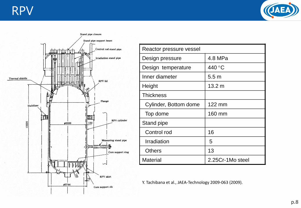
RPV
p.8
Reactor pressure vessel
Design pressure 4.8 MPa
Design temperature 440 C
Inner diameter 5.5 m
Height 13.2 m
Thickness
Cylinder, Bottom dome 122 mm
Top dome 160 mm
Stand pipe
Control rod 16
Irradiation 5
Others 13
Material 2.25Cr-1Mo steel
Y. Tachibana et al., JAEA-Technology 2009-063 (2009).

Primary Pressurized Water Cooler (PPWC)
p.9
Primary pressurized water cooler
type Vertical U-tube
Design pressure 4.8MPa
Design temperature 430 C
Flow rate
Primary coolant Max. 45t/h
Cooling water Max. 640t/h
Temperature
Primary coolant Max. 950 C
Cooling water Inlet 150 C /outlet 190 C
Tube
Number 136
Outer diameter 25.4 mm
Thickness 2.6 mm
Outer diameter of shell 2.1 m
Overall height 7.1 m
Material 2.25Cr-1Mo steel (shell)
Stainless steel (tube)
T. Furusawa et al., Nucl. Eng. Des., 233113-124 (2004).

p.10
Intermediate Heat Exchanger (IHX)
Intermediate heat exchanger
Type Vertical helically-coiled
counter-flow heat
exchanger
Heat transfer rate 10 MW
Design pressure 4.8 MPa (shell)
0.3 MPa (tube)
Design temperature 430 C (shell)
955 C (tube)
Shell
Outer diameter 2 m
Overall height 11.0 m
Tube
Number 96
Outer diameter 31.8 mm
Thickness 3.5 mm
Material 2.25Cr-1Mo steel (shell)
Hastelloy XR (tube)
T. Furusawa et al., Nucl. Eng. Des., 233113-124 (2004).

p.11
Gas Circulator
IHX HGC PPWC HGC
Type Vertical centrifugal/gas bearing type
Number 1 3
Flow mass rate (max.) 15t/h 15t/h
Head (max.) 794kPa 1,080kPa
Allowable working press. 4.8MPaG 4.8MPaG
Allowable working temp. 430C 430C
Filter type Sintering material
Motor type Cage type induction motor
Motor power 190kW 260kW
Number of revolutions 3,000-12,000rpm 3,000-12,000rpm
Frequency converter
type
Thyristor-converter
T. Furusawa et al., Nucl. Eng. Des., 233, 113-124 (2004).

p.12
Containment Vessel
Containment type Steel containment
Maximum service pressure 0.4MPa
Maximum service temperature 150C
Major size
Inner diameter 18.5m
Overall height 30.3m
Body thickness 30mm
Top lid thickness 38mm
Refueling hatch diameter 8.5m
Maintenance hatch diameter 2.4m
Air lock diameter 2.5m
Free volume 2800m3
Material Carbon steel
Leak rate 0.1%/day at R.T.&
0.36MPa
C/V solely stands on the base mat without any support
S. Saito et al., JAERI-1332 (1994).

p.13
Purification System
Type Number Helium flow rate
Pre-charcoal trap Vertical cylinder 1 200kg/h
CuO fixed bed Vertical cylinder 2 200kg/h
Molecular sieve trap Vertical cylinder 2 200kg/h
Cold charcoal trap Vertical cylinder 2 50kg/h
N. Sakaba et al., NED, 233, 147-154 (2004).

p.14
Helium Storage and Supply System
Storage tank Number 6
Tank volume About 18m3/tank
Capacity About 1320kg (total)
Max. pressure 8.6MPa
Supply tank Number 1
Tank volume About 10m3/tank
Capacity About 110kg (total)
Max. pressure 8.6MPa
Y. Tachibana et al., JAEA-Technology 2009-063 (2009).

p.15
Instrumentation and Control
K. Saito et al., Nucl. Eng. Des., 233, 125-133 (2004).

p.16
Nuclear Instrumentation
Y. Tachibana et al., JAEA-Technology 2009-063 (2009).

p.17
Reactor Power Control System
Operation mode selector
Rated power operation
High temperature operation
Safety demonstration test operation
Reactor power control system
Power control
Reactor outlet temperature control
Detector
Neutron flux
Reactor outlet coolant temperature
S. Saito et al., JAERI-1332 (1994).
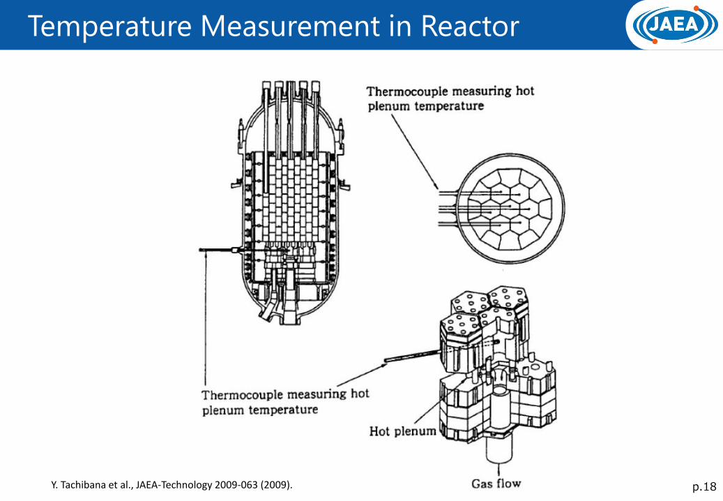
p.18
Temperature Measurement in Reactor
Y. Tachibana et al., JAEA-Technology 2009-063 (2009).
p.19
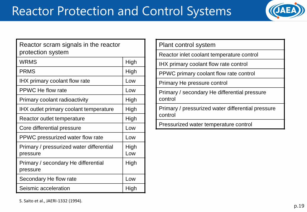
Reactor Protection and Control Systems
Reactor scram signals in the reactor
protection system
WRMS High
PRMS High
IHX primary coolant flow rate Low
PPWC He flow rate Low
Primary coolant radioactivity High
IHX outlet primary coolant temperature High
Reactor outlet temperature High
Core differential pressure Low
PPWC pressurized water flow rate Low
Primary / pressurized water differential
pressure
High
Low
Primary / secondary He differential
pressure
High
Secondary He flow rate Low
Seismic acceleration High
Plant control system
Reactor inlet coolant temperature control
IHX primary coolant flow rate control
PPWC primary coolant flow rate control
Primary He pressure control
Primary / secondary He differential pressure
control
Primary / pressurized water differential pressure
control
Pressurized water temperature control
S. Saito et al., JAERI-1332 (1994).

p.20
Control Rod
Control
rod
Type Double circular cylinders
with lid and vent
Number 16 pairs (32 rods)
Total length 3.1m
Outer dia. 113mm
Inner dia. 65mm
Sleeve material Alloy 800H
Neutron
absorber
Outer dia. 105mm
Inner dia. 75mm
Material Sintered compact of
B4C/C
Excess
reactivity
Temp. loss and FP buildup 0.088k/k
Burnup 0.043 k/k
Reactivity margin 0.018 k/k
Uncertainties 0.016 k/k
Total 0.165 k/k
Shutdown
margin
CR controllable reactivity > 0.18 k/k
CR shutdown margin > 0.01 k/k
S. Saito et al., JAERI-1332 (1994).

p.21
Fuel Failure Detection System
Type Precipitator
Number 2
Sampling nuclide 88Kr, 138Xe
Flowrate 0.5kg/h/channel
Temperature up to 50 C
• Fuel failure detection system detects the
failure of a CFP by detecting short life FPs,
such as Kr-88 asn Xe-138, which are
gathered with precipitating wiring.
• Helium gas of the outlet core from seven
regions are transferred to the line selector.

p.22
Vessel Cooling System
Line 2
Removal
heat
Rated operation <0.6MW / 2 Lines
In accident >0.3MW / 1 Line
Cooling pipe inlet water
temperature
44C
Available working
temperature
90C
Water flow rate 86t/h
• VCS is used as a residual heat removal
system when the forced helium circulation can
not maintained due to failure of concentric hot
gas duct.
• VCS is an engineering safety system so that
two independent complete sets are provided.
Y. Tachibana et al., JAEA-Technology 2009-063 (2009).

p.23
Auxiliary Cooling System
Line 1
Removal heat 3.5MW
Available working
temperature
Cold leg 430C
Hot leg 980C
Primary coolant mass flow rate 3t/h (one GC)
4.3t/h (two GCs)
• Auxiliary cooling system
automatically starts up at reactor
scram.
• ACS is an engineering safety
system so that a pair of GCs and
water pumps are provided.
Y. Tachibana et al., JAEA-Technology 2009-063 (2009).

p.24
Support Structures for RPV, IHX and PPWC
• RPV is supported by skirt, stabilizer at cylinder and vibration control beam at standpipe.
• IHX and PWC is supported by constant hanger and snubber.
Snubbers
Hangers Skirt
Stabilizer
Vibration Control beam
Y. Tachibana et al., JAEA-Technology 2009-063 (2009).

p.25
HTTR Operation Experiences (1/2)
• Unexpected temperature rise was observed in upper shielding.
• The temperature rise is due to bypass flow which flow upwards along standpipe wall
Y. Tachibana et al., JAEA-Technology 2009-063 (2009).
• Unexpected temperature rise was observed in upper shielding.
• The temperature rise is due to bypass flow which flow upwards along standpipe wall
• To reduce the bypass flow, flow resistance in main flow path is reduced by adding holes on the side of guide pipe and top plate of the CR guide tube.
• The gaps for the CR drive mechanism is sealed with synthetic rubber gaskets.

p.26
HTTR Operation Experiences (2/2)
• Unexpected temperature rise was observed in center part of core support plate.
• The temperature rise is due to gap flow from core hot plenum to inside of concentric hot gas duct.
Y. Tachibana et al., JAEA-Technology 2009-063 (2009).
• Detail calculation was conducted considering the gap flow to confirm that the temperature would not exceed the design temperature limit.

p.27
High Temperature Continuous Operation
To establish fundamental technologies of HTGR To demonstrate stable high temperature heat supply to a heat
application system
Purpose
Evaluation of core physics
Evaluation of fuel performance (FP retention)
Evaluation of impurity control technology in helium coolant
Evaluation of IHX performance
Evaluation of structural integrity of components
Accumulation of operation and maintenance technologies

p.28
Operation Record
0
10
20
30
40
1/4 1/11 1/18 1/25 2/1 2/8 2/15 2/22 3/1 3/8 3/15 3/22
Date (month/day)
The
rmal
pow
er (
MW
)
50 days high-temperature operationHigh-temp. operation for 50 days
Control room
Date (month/day/2010)
50-days continuous operation
Rea
cto
r p
ow
er [
MW
t]
Date in 2010
K. Takamatsu et al., JAEA-Research 2010-038 (2010).

p.29
Main Results (1/2)
Long stability of condition
Flow rate and temperature of coolant were kept very stable.
Parameters Fluctuation
Nuclear power ±0.4 %
Coolant temp. About 3 oC
Coolant flow ±0.5 %
High controllability of excess activity
Insert depth of control rod was kept shallow and mostly constant.
Good confinement of FPs
Fractional release of Kr88 from coated fuel was kept very low.

p.30
Main Results (2/2)
Stable shielding
Temperature of shielding concrete around RPV was kept stable.
Low impurity of coolant
Impurity such as water, CO and H2 in the coolant was kept low .
High integrity of IHX
High temperature heat could be stably supplied through IHX.

p.31
Fuel Performance (1/3)
to
auxiliary
cooling
system
Reactor
PPWC
IHX
to SPWC
By-pass line
HGC
HGC
To pressurized water cooling system
(1) ionization chamber of PCR instrumentation
(3) the primary coolant sampling
Precipitators
(2) FFD system
Measurement of the radioactivity in the primary cooling system is performed by
(1) The primary coolant radioactivity (PCR) instrumentation of the safety protection system
(2) The fuel failure detection (FFD) system
(3) The primary coolant sampling system
Y. Tachibana et al., JAEA-Technology 2009-063 (2009).

p.32
Fuel Performance (2/3)
Radioactivity in the primary cooling system was below the lower detection limit of about 14Bq/cm3
Detector: gamma-ray detection
0
25
50
75
100
1e-6
1e-5
1e-4
1e-3
1e-2
1/5 1/15 1/25 2/4 2/14 2/24 3/6 3/1610-6
10-4
10-3
10-2
10-5
104
103
102
10
1
100
75
50
25
0
Reactor power
Lower detection limit
Radioactivity in the primary cooling system
Reacto
r po
wer (%
) R
adio
acti
vity
(B
q/c
m3)
Date in 2010
1/5 1/15 1/25 2/4 2/14 2/24 3/6 3/16
(1) The primary coolant radioactivity (PCR) instrumentation of the safety protection system

p.33
Fuel Performance (1/2)
Precipitator(A)
FFD system
Precipitator(B)
1
7 2
3
4 5
6
(2) The fuel failure detection (FFD) system
No significant differences of counting rate were observed among 7 regions.
Detector: NaI (Tl) scintillation counter 1.05
1.03
1.05
0.97
0.95
1.07
1.04
1.08
0.98
0.96
Rat
io o
f co
un
tin
g ra
te
0.88
0.92
0.96
1.00
1.04
1.08
FFD-1/2 FFD-3/2 FFD-4/2 FFD-6/5 FFD-7/5
K. Takamatsu et al., JAEA-Research 2010-038 (2010).

p.34
Fuel Performance (3/3)
1/4 1/11 1/18 1/25 2/1 2/8 2/15 2/22 3/1 3/8 3/15 3/22
(3) The primary coolant sampling system
Kr concentrations were lower than about 0.1 Bq/cm3
10-4
10-5
10-6
10-7
10-8
10-9
HTTR
50-days continuous operation
1/4 1/18 2/1 3/1 3/15 2/15 3/22
Date in 2010
(R/B
) o
f 8
8K
r
Ref 1: T. Tochio et al., JAEA-Technology 2010-038 (2010). Ref 2: K. Takamatsu et al., JAEA-Research 2010-038 (2010).

p.35
Safety Demonstration Test
Reduction of primary coolant flow rate
Increase of reactivity by withdrawal of the central pair of control rods
Reactor
Primary Pressurized
Water Cooler
Core
Gas Circulators
Control Rods
Fuel Region Reflector Region
Core
Reactivity Insertion Test Coolant Flow Reduction Test
from partial reduction to total loss

p.36
Reactivity insertion test – CR withdrawal test -
Test conditions
Reactor power 30% - 80%
(30%, 50% and 60% tests has been conducted)
Control rods to be withdrawn Central pair
(16 pairs (total))
Withdrawal speed 1 and 5 mm/s
Withdrawal distance 10mm - 40mm
Reactor power control system Disabled
Reactor outlet coolant temperature
Initial Below 850℃
During Test Below 950℃
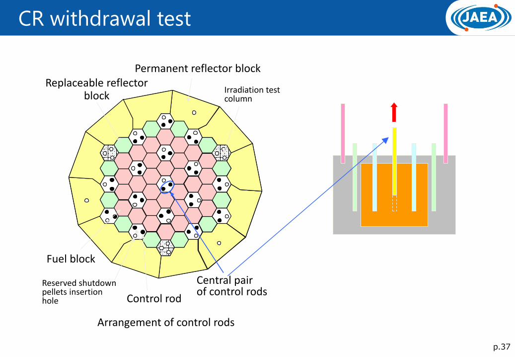
p.37
CR withdrawal test
Arrangement of control rods
Permanent reflector block Replaceable reflector
block
Fuel block
Control rod
Reserved shutdown pellets insertion hole
Central pair of control rods
Irradiation test column

p.38
Coolant flow reduction test
Test conditions
Reactor power 30% - 100%
(30% and 60% tests has been conducted)
Gas circulators to be stopped 1 or 2 (out of 3)
Reactor power control system Disabled
Reactor outlet coolant temperature
Initial Below 850℃
During Test Below 950℃
Scram set point of flow rate
93% → 27%
Reactor
Primary Pressurized Water
Cooler
Core
Gas Circulators

p.39
Loss of Forced Cooling Test
Auxiliary cooling system
Secondary pressurized water cooler (SPWC)
Reactor
Vessel cooling system (2 units)
Loss of forced cooling (LOFC) & Loss of vessel cooling (LOVC) simulation of station blackout
Upper panel
Side panel
Heat removal adjustment
panel
Water cooling tube
Upper radiation shielding
Lower panel
RPV
Radiation shielding
Thermal reflector plate
Vessel cooling system (VCS)
Cooling water
: Stop of circulator and pump
Primary pressurized water cooler (PPWC)
Intermediate heat exchanger (IHX)
Heat
Core is cooled from the outside by radiation and natural convection.

p.40
Loss of Forced Cooling Test
Test conditions
Reactor power 30%, 80%, 100%
Gas Circulators to be Stopped 3 (All the GCs)
Reactor power control system Disabled
Reactor Outlet Coolant Temperature
Initial Below 850℃
During Test Below 950℃
Reactor scram due to decrease of primary coolant flow rate Bypassed during test

p.41
Loss of Forced Cooling Test
Loss of forced cooling test (LOCF test) : Stop of all circulators in primary circuit
Increase of reactor core temperature
Reactor power and fuel temperature
remain in stable condition
Stop of all primary circulators flowrate of primary coolant : 100% → 0%)
Decrease of reactor power due to negative reactivity feedback
( resonance absorption of neutron in U238)
41
Test Condition
• Initial reactor power 30% (9MW) • Without scram (no movement of CR)
Test Results
Elapsed time (hr) 0 1 2 3 4 5 6
Stop of circulator
Core flow rate Test result
Reactor power
Test result
Peak fuel temperature
Analytical result
100
50
0
30
15
0
1600
800
0
Flo
w r
ate
(%)
Pow
er
(%
)
Tem
p.
(oC
)
Dec.21, 2010 Test Date
p.42
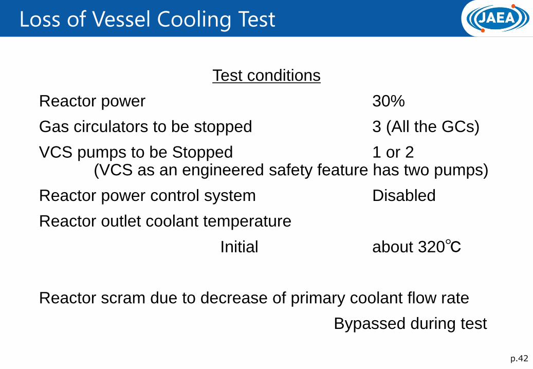
Loss of Vessel Cooling Test
Test conditions
Reactor power 30%
Gas circulators to be stopped 3 (All the GCs)
VCS pumps to be Stopped 1 or 2 (VCS as an engineered safety feature has two pumps)
Reactor power control system Disabled
Reactor outlet coolant temperature
Initial about 320℃
Reactor scram due to decrease of primary coolant flow rate
Bypassed during test