HTS 580 Series Total Station
244
1 1. PREPARATION 1.1 Precautions 1. Never point the instrument at the sun without a filter. 2. Never store the instrument in extreme temperatures and avoid sudden changes of temperature. 3. When not using the instrument, place it in the case to avoid shock, dust, and humidity. 4. If there is a great difference in temperature between the work site and the instrument storage location leave the instrument in the case until it adjusts to the temperature of the surrounding environment. 5. Please remove the battery for separate storage if the instrument is to be in storage for an extended time. The battery should be charged once a month during storage. 6. The instrument should be placed in its carrying case during transportation. It is recommended that the original packing case be used for cushioning during extended transportation. 7. Be sure to secure the instrument with one hand when mounting or removing from the tripod. 8. Clean exposed optical parts with degreased cotton or lens tissue only. 9. Clean the instrument's surface with a woolen cloth when finished with use. Dry it immediately if it gets wet. 10. Check the battery, functions, and indications of the instrument as
Transcript of HTS 580 Series Total Station

1
1. PREPARATION
1.1 Precautions1. Never point the instrument at the sun without a filter.
2. Never store the instrument in extreme temperatures and avoid
sudden changes of temperature.
3. When not using the instrument, place it in the case to avoid shock,
dust, and humidity.
4. If there is a great difference in temperature between the work site
and the instrument storage location leave the instrument in the case until it
adjusts to the temperature of the surrounding environment.
5. Please remove the battery for separate storage if the instrument is to
be in storage for an extended time. The battery should be charged once a
month during storage.
6. The instrument should be placed in its carrying case during
transportation. It is recommended that the original packing case be used for
cushioning during extended transportation.
7. Be sure to secure the instrument with one hand when mounting or
removing from the tripod.
8. Clean exposed optical parts with degreased cotton or lens tissue
only.
9. Clean the instrument's surface with a woolen cloth when finished
with use. Dry it immediately if it gets wet.
10. Check the battery, functions, and indications of the instrument as

2
well as its initial setting and correction parameters before operating.
11. Unless you are a maintenance specialist do not attempt to
disassemble the instrument for any reason. Unauthorized disassembly of
the instrument can result in a void warranty.
12. The total stations emit a laser during operation. DO NOT stare into
the beam or laser source when instrument is operation.
3
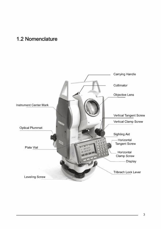
1.2 Nomenclature

4
5
1.3 Unpacking and Storage of the InstrumentUnpacking of the Instrument
Place the case lightly with the cover upward, unlock the case and take
out the instrument.
Storage of the Instrument
Replace the cover on the telescope lens, place the instrument into the
case with the vertical clamp screw and circular vial upward (objective lens
toward the tribrach), tighten the vertical clamp screw, close and lock the
case.
1.4 Instrument Set UpMount the instrument onto the tripod and secure firmly. Level and
center the instrument precisely to ensure the best performance. Use a
rugged tripod with a 5/8” tripod screw. Our Fiberglass SL180FGB tripods
are highly recommended.
Operation Reference: Leveling and Centering the Instrument
1). Setting up the tripod
First extend the extension legs to suitable length and tighten the
screws, firmly plant the tripod in the ground over the point of beginning.
2). Attaching the instrument to the tripod
Secure the instrument carefully on the tripod and slide the instrument
by loosening the tripod mounting screw. If the optical plumb site is
positioned over the center of the point tighten the mounting screw.
6
3). Roughly leveling the instrument by using the circular vial
Turn the leveling screw A and B to move the bubble in the circular vial,
in which case the bubble is located on a line perpendicular to a line running
through the centers of the two leveling screw being adjusted. Turn the
leveling screw C to move the bubble to the center of the circular vial.
Recheck the position of the instrument over the point and adjust if needed.
4). Leveling by using the plate vial
Rotate the instrument horizontally by loosening the Horizontal Clamp
Screw and place the plate vial parallel with the line connecting leveling
screws A and B, then bring the bubble to the center of the plate vial by
turning the leveling screws A and B.
Rotate the instrument 90° (100g) around its vertical axis and turn the
remaining leveling screw or leveling C to center the bubble once more.
Repeat the procedures for each 90° (100g) rotation of the instrument
and check whether the bubble is correctly centered in all directions.
5). Centering by using the optical plummet(or laser plumment)
Adjust the eyepiece of the optical plummet telescope to your eyesight.
Slide the instrument by loosening the tripod screw; place the point on the
center mark of the optical plummet. Sliding the instrument carefully as to not
rotate the axis will allow you to get the least dislocation of the bubble.(Place
star-key after power on, then press F4(LASER)key, press F1(ON)key to turn
on the laser plumment. Slide the instrument by loosening the tripod screw;
Place laser facular on the occupied pointing, Sliding the instrument carefully
as to not rotate the axis will allow you to get the least dislocation of the
bubble. The last, press ESC key, and laser plummet turn off automatically.)

7
6). Complete leveling the instrument
Level the instrument precisely as in Step 4. Rotate the instrument and
check to see that the bubble is in the center of the plate level regardless of
the telescope direction then tighten the tripod screw firmly.
1.5 Battery Removal & Insertion - Information andRecharging
Battery removal & insertion
Insert the battery into the battery slot and push the battery until it clicks.
Press the right and left buttons of the battery compartment to remove
the battery.
Battery information
------------- Indicates that battery is fully charged
------------- Indicates that the battery can only be used for about
1 hour.
Recharge the battery or prepare a recharged
battery for use.
------------- Recharge the battery or prepare a recharged

8
battery for use.
Note: The working time of the battery is determined by environment
conditions, recharging time, and other factors.
Battery Recharging
Battery should be recharged only with the charger supplied with the
instrument.
Remove the on-board battery from instrument as instructed and
connect to the battery charger.
Battery Removal Caution
▲Before you take the battery out of the instrument, make sure that the
power is turned off. Otherwise the instrument can be damaged.
Recharging Caution:
▲The charger has built-in circuitry for protection from overcharging.
However, do not leave the charger plugged into the power outlet after
recharging is completed.
▲Be sure to recharge the battery at a temperature of 0℃~45℃,
recharging may be abnormal beyond the specified temperature range.
▲When the indicator lamp does not light after connecting the battery
and charger the battery or the charger may be damaged.
Storage Caution:
▲The rechargeable battery can be repeatedly recharged 300-500 times.
Complete discharge of the battery may shorten its service life.
▲In order to get the maximum service life be sure to recharge the
battery at least once a month.

9
1.6 Reflector PrismsWhen doing distance measuring in prism mode a reflector prism
needs to be placed as the target. Reflector systems can be single or
multiple prisms which can be mounted with a tripod/tribrach system or
mounted on a prism pole. Unique mini prism systems allow setups at
corners that are hard to reach. Reflectorless targets extend the range of the
instrument when used in reflectorless mode.
Illustrated are some prisms and a reflector compatible with
instruments:
10
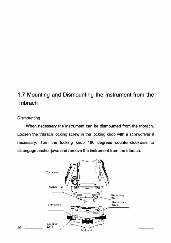
1.7 Mounting and Dismounting the Instrument from theTribrach
Dismounting
When necessary the instrument can be dismounted from the tribrach.
Loosen the tribrach locking screw in the locking knob with a screwdriver if
necessary. Turn the locking knob 180 degrees counter-clockwise to
disengage anchor jaws and remove the instrument from the tribrach.
11
Mounting
Insert three anchor jaws into holes in tribrach and line up the directing
stub on the instrument with the directing slot of the tribrach. Turn the locking
knob 180 degrees clockwise and tighten the locking screw with a
screwdriver.
1.8 Eyepiece Adjustment and Object SightingMethod of Object Sighting (for reference)
Sight the telescope to the sky and rotate the eyepiece tube to make the
reticule clear.
Collimate the target point with top of the triangle mark in the collimator.
(keep a certain distance between eye and the collimator).
Make the target image clear with the telescope focusing screw.
If there is parallax when your eye moves up and down or left and right
this indicates the diopter of the eyepiece lens or focus is not adjusted well
and accuracy will be effected. You should readjust the eyepiece tube
carefully to eliminate the parallax.
1.9 Turning the instrument On and OffPower on
1. Be sure that the instrument is leveled.
2. Press and momentarily hold the power (POWER) key.

12
3. Rotate the EDM head in an upwards direction to initialize.
4. To turn OFF press and hold the power key until instrument powers
down.
Be sure there is sufficient battery power. If 'Battery Empty' is shown on
the display, the battery should be recharged or replaced.
*** DO NOT remove the battery during measuring, otherwise the data will be
lost and the instrument could be harmed!! ***
1.10 How To Enter Alphanumeric Characters*How to select an item
[Example 1] Select INS.HT (instrument height) in the data collection
mode (first press the MENU button then F1:DATA COLLECT and then
select the data file desired. Press F2 to list, the arrow keys to choose and
then F4 to select). Press F1 again for OCC.PT# INPUT.
The arrow (→) indicates an item to enter. Press [▲] [▼] key to move the
arrow line up or down
Press [▼] move->R..HT

13
Press F1 INPUT then 1 to input“1”Press . to input “. ”Press 5 to input “5 ”, press ENTThen R. HT =1.5 m
*How to enter characters[Example 2] Input the code “ABC1”of instrument point in Data CollectionMode.
1.Move the arrow to PCODE using the [▲]or [▼]key
2.Press F1 (input) key
14
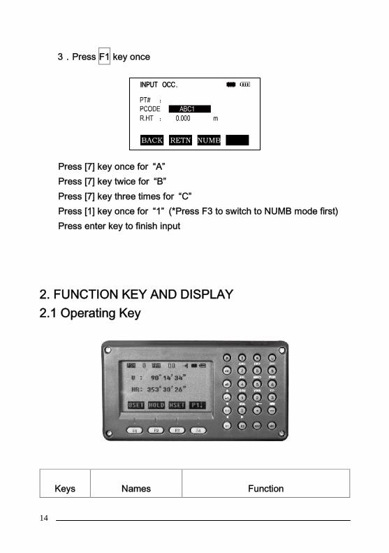
3.Press F1 key once
Press [7] key once for “A”Press [7] key twice for “B”Press [7] key three times for “C”Press [1] key once for “1” (*Press F3 to switch to NUMB mode first)Press enter key to finish input
2. FUNCTION KEY AND DISPLAY2.1 Operating Key
Keys Names Function

15
ANG Angle meas. key Angle measurement mode
Distance meas. key Distance measurement modeCoordinate meas.key
Coordinate measurement mode
( Up)
S.O Layout key Layout measurement mode (
Down)
K1 Quick key1 User-defined quick key 1( Left)
K2 Quick key 2 User-defined quick key 2( Right)
ESC Escape key Return to the measurement mode orprevious layer mode.
ENT Enter key Press after confirmation of inputtingvalues
M Menu key Switches menu mode and normal
mode
T Shift key Shift distance measuring key
Star keyPress once to adjust contrast or twicefor illumination of keypad
Power key On / Off key press and holdF1- F4 Soft key ( Function
key)Responds to the message displayed
0- 9 Number key Input numbers
— Minus key Input minus sign, displays electronicbubble
. Point key On / Off laser pointing function
Display marks:
Display ContentV Vertical angle

16
V% Vertical angle as a percentage (Gradient display)
HR Horizontal angle (right)
HL Horizontal angle (left)
HD Horizontal distanceVD Elevation difference
SD Slope distance
N North coordinate
E East coordinate
Z Z or elevation coordinate
* EDM workingm/ft Switches units between meters and feet
m Meter unit
S/A Sets temperature, air pressure, prism constant
PSM Prism constant (unit:mm)
PPM Atmospheric correction
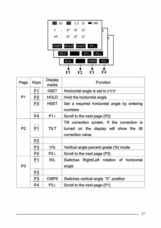
2.2 Function KeyAngle measurement mode (three-page menu)
17
Page Keys Displaymarks Function
P1F1 0SET Horizontal angle is set to 0°0′0″
F2 HOLD Hold the horizontal angleF3 HSET Set a required horizontal angle by entering
numbersF4 P1↓ Scroll to the next page (P2)
P2 F1 TILTTilt correction screen. If the correction isturned on the display will show the tiltcorrection value.
F2F3 V% Vertical angle percent grade (%) modeF4 P2↓ Scroll to the next page (P3)
P3F1 R/L Switches Right/Left rotation of horizontal
angleF2F3 CMPS Switches vertical angle “0” positionF4 P3↓ Scroll to the next page (P1)

18
Distance measurement mode (two-page menu)
Page Keys Display marks Function
P1F1 MEAS Begin measuringF2 MODE Sets measuring mode,
Fine/--/TrackingF3 S/A Sets temperature, air pressure, prism
constantF4 P1↓ Scroll to the next page (P2)
P2F1 OFSET Selects Off-set measurement modeF2 S.O. Selects Stake Out measurement
modeF3 m / ft Switches units between meters and
feetF4 P2↓ Scroll to the next page (P1)

19
Coordinate measurement mode(three-page menu)

20
2.3 star-key modeThe total station(non-reflectorless):
Press the star key , following is displayed:
Page Keys Displaymarks
Function
P1F1 MEAS Start measuringF2 MODE Sets a measuring mode, Fine/TrackingF3 S/A Sets temperature, air pressure, prism
constantF4 P1↓ The function of soft keys is shown on
next page (P2)
P2F1 R.HT Sets prism heightF2 INSHT Sets instrument heightF3 OCC Sets instrument coordinate.F4 P2↓ Shows the function of soft keys on page
3
P3
F1 OFSET Off-set measurement modeF2 BACKSIGHT Setting a direction angle for backsight
orientationF3 m / ft Switches meter and feet unit.F4 P3↓ Shows the function of soft keys on
page1

21
1. Contrat adjustment: After pressing star key, adjust the display
contrast by pressing [▲] or [▼] key.
2. Illumination: After pressing star key, select [Illumination] by pressing
F1(LAMP) key or press star key.
3. Tilt: After pressing star key, select [tilt] by pressing F2 (TILT) key,
and select ON or OFF by pressing F1 or F3 key, press F4 (ENT) key.
4. S/A: After pressing star key, select [S/A] by pressing F3 (S/A) key,
then you can set Prism contrast, air pressure and temperature.
5. Laser plumment: If total station has this function, after pressing star
key, select [laser] by pressing F4 (LASR) key, and select ON or OFF by
pressing F1 or F2 key.
*In some interface, you can turn on or turn off panel backlight by press
star key directly.
The total station(with reflectorless):Press the star key , following is displayed:
1.Mode: Press the F1 (mode) key, the following is displayed :
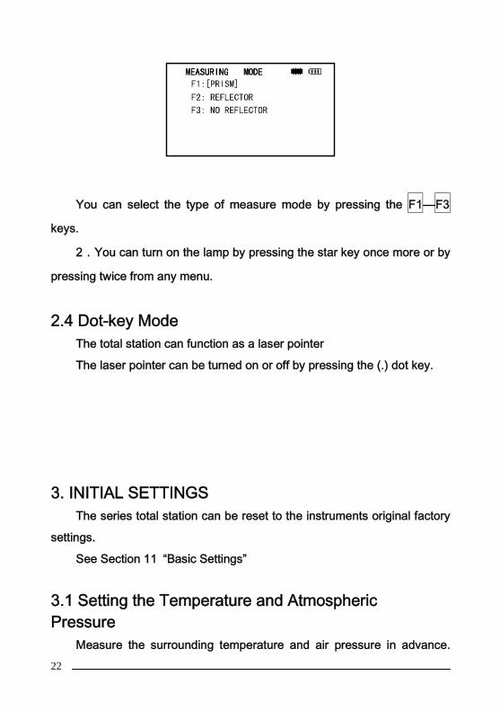
22
You can select the type of measure mode by pressing the F1—F3
keys.
2.You can turn on the lamp by pressing the star key once more or by
pressing twice from any menu.
2.4 Dot-key ModeThe total station can function as a laser pointer
The laser pointer can be turned on or off by pressing the (.) dot key.
3. INITIAL SETTINGSThe series total station can be reset to the instruments original factory
settings.
See Section 11 “Basic Settings”
3.1 Setting the Temperature and AtmosphericPressure
Measure the surrounding temperature and air pressure in advance.
23
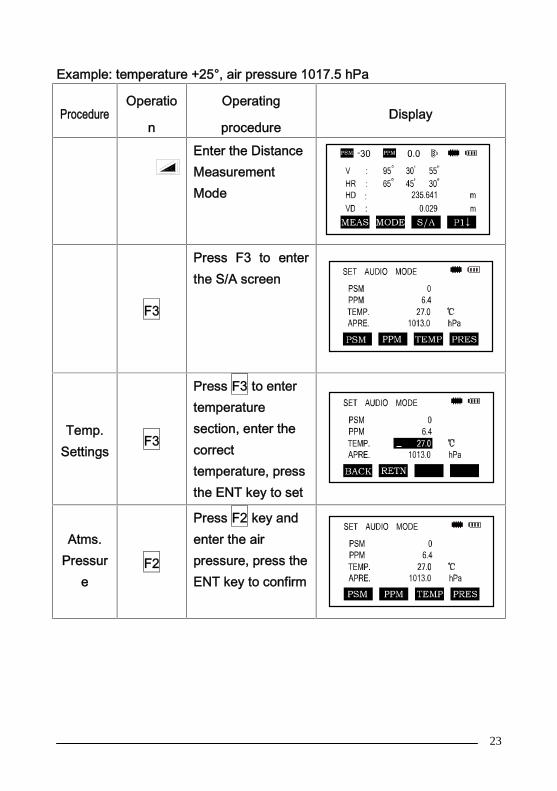
Example: temperature +25°, air pressure 1017.5 hPa
ProcedureOperatio
n
Operating
procedureDisplay
Enter the DistanceMeasurementMode
F3
Press F3 to enterthe S/A screen
Temp.Settings
F3
Press F3 to entertemperaturesection, enter thecorrecttemperature, pressthe ENT key to set
Atms.Pressur
eF2
Press F2 key andenter the airpressure, press theENT key to confirm

24
Remarks
Temperature operating range:-30°~+60℃ or -22~+140℉Air pressure:560~1066 hPa or 420~800 mmHg or 16.5~31.5inHgIf the atmospheric correction value calculated from thetemperature and air pressure exceeds the range of ±999.9PPM,the operation will return to step 4 automatically, andyou should enter the data again.
3.2 Setting of the Atmospheric CorrectionThe infrared emitted by the Total Station varies with the air temperature
and pressure. Once the atmospheric correction value is set the instrument
will correct the distance measuring result automatically.
Air pressure: 1013hPa
Temperature: 20℃
The calculation of atmospheric correction :
ΔS =273.8 – 0.2900 P / ( 1 + 0.00366T )(ppm)
ΔS:Correction Coefficient (Unit ppm)
P: Air Pressure (Unit : hPa If the unit is mmHg , please convert
using
1hPa = 0.75mmHg
T: temperature ( unit℃)
Direct Setting Method of Atmosphere Correction Value
After measuring the temperature and air pressure the atmosphere

25
correction value can be obtained from an atmospheric correction chart or
correction formula (PPM).
3.3 Setting of the Prism Constant
Procedure
Operation
Operation Procedure Display
F3
Press F3 Key indistancemeasurement orcoordinatemeasurement mode
F2Press F2 [ppm] key,which shows thecurrent setting value
Entervalue
Enter atmosphericcorrection and pressENT
*1)See 2.10“How to Enter Alphanumeric Characters”Input range:-999. 9PPM to +999. 9 Step length: 0 .1PPM*2)If Temperature and Atmospheric Pressure are reset, the PPM will berecalculated automatically.

26
In the factory the prism constant for the total station is set at -30mm. If
the constant of the prism used is not -30mm, you must change this setting.
Once the prism constant is set it will become the new default value until
changed.
Procedure Operation Operation
Procedure
Display
F3
Press F3 ( S/A )Key in DistanceMeasurementModeor Coord.MeasurementMode.
② F1② Press F1(PRISM)key
③Enterdata
Press F1 (INPUT)key to enter thePrism Constantcorrection value.*1, press F4 toconfirm and returnto the SettingMode.
Input range:-99. 9mm to +99. 9mm Step length 0. 1mm
*The total station in reflectorless measuring mode sets the prism constant to

27
0 automatically.
3.4 Setting of the Vertical Angle Tilt CorrectionWhen the tilt sensor is activated the instrument automatically corrects
the vertical angle for mislevel. To ensure a precise angle measurement the
tilt sensor must be turned on. The tilt sensor display can also be used to fine
level the instrument. If the (“X TILT OVER”) display appears the instrument
is out of the automatic compensation range and must be leveled manually to
within tolerances.
The instruments compensates the vertical angle reading due to
inclination of the standing axis in the X direction.
When the instrument is on an unstable footing or used during a windy
day the display of vertical angle can be unstable. You can turn off the auto
tilt correction function in this case.
Setting the tilt correction
The instrument memorizes the last setting for this feature. To insure the
compensator is on check this setting before operating the instrument.
For operation procedures refer to 11.2.1.
28
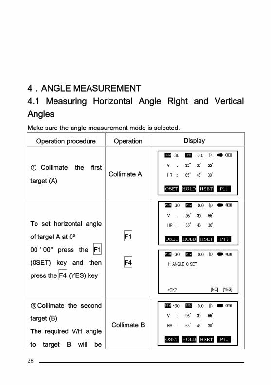
4.ANGLE MEASUREMENT4.1 Measuring Horizontal Angle Right and VerticalAnglesMake sure the angle measurement mode is selected.
Operation procedure Operation Display
① Collimate the first
target (A)Collimate A
To set horizontal angle
of target A at 0º
00 ’ 00" press the F1
(0SET) key and then
press the F4 (YES) key
F1
F4
③Collimate the second
target (B)
The required V/H angle
to target B will be
Collimate B

29
displayed
Note : The horizon angle will be saved when the instrument is powered off
and displayed when powered on.
Reference: How to Collimate
Point the telescope toward a light surface or sky. Turn the diopter ring and
adjust the diopter so that the cross hairs are clearly observed.
Aim the target at the peak of the triangle mark of the sighting collimator.
Allow a certain space between the sighting collimator and yourself for
collimating.
Focus the target with the focusing knob.
If parallax is created between the cross hairs and the target when viewing
vertically or horizontally while looking into the telescope, focusing is
incorrect or diopter adjustment is poor.
This adversely affects precision in measurement please eliminate the
parallax by carefully focusing and using the diopter adjustment.

30
4.2 Switching Horizontal Angle Right/LeftMake sure the angle measurement mode is selected.
Operation procedure Operation Display
Press the F4 Key twice to get
the menu to page 3. (P3)
F4
twice
Press the F1(R/L)key.
The Horizontal Right angle
mode (HR) Switches to
Horizontal Left mode (HL)
F1
Measure as HL mode

31
*Each time the F2 (R/L) key is pressed the HR/HL mode switches
4.3 Setting of the Horizontal Angle4.3.1 Setting by Holding the AngleMake sure the angle measurement mode is selected.
Operation procedure Operation Display
① Set the required
horizontal angle using the
horizontal tangent screw
Display
angle
②Press the F2 (HOLD)keyF2
③Collimate the target Collimate

32
④Press the F4 (YES) key
to finish holding the
horizontal angle, the
display turns back to the
normal
angle measurement mode
F4
*To return to the previous mode, press the ESC key.
4.3.2 Setting the Horizontal Angle from the KeypadMake sure the angle measurement mode is selected.
Operation procedure Operation Display
①Collimate the target Collimate
②Press the F3 (HSET) keyF3
33
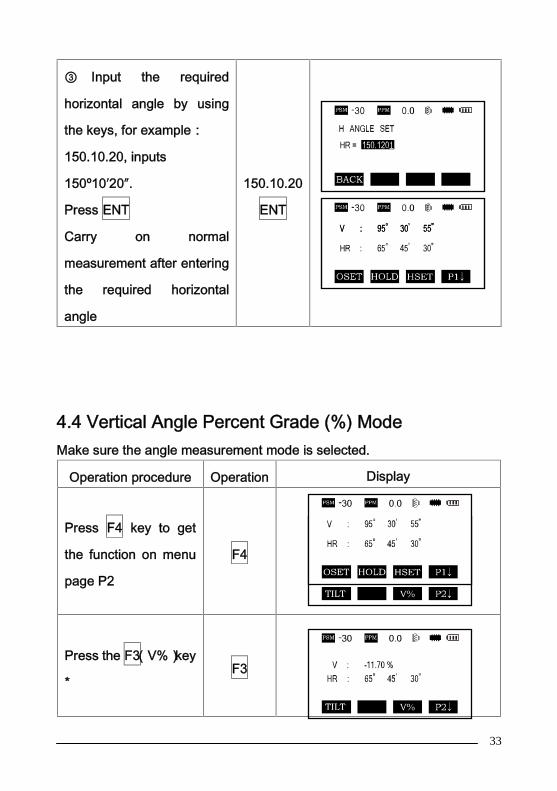
③ Input the required
horizontal angle by using
the keys, for example:
150.10.20, inputs
150º10′20″.
Press ENT
Carry on normal
measurement after entering
the required horizontal
angle
150.10.20
ENT
4.4 Vertical Angle Percent Grade (%) ModeMake sure the angle measurement mode is selected.
Operation procedure Operation Display
Press F4 key to get
the function on menu
page P2
F4
Press the F3(V%)key
*F3

34
*Each time the F3(V%)key is pressed the display mode switches.
When the angle measured is over 45°(100%)from the horizontal
<OVERTOP> is displayed.
4.5 Setting the Initial Zenith AngleVertical angle is displayed as shown below:
Make sure the angle measurement mode is selected.
Operation procedure Operation Display

35
Press F4 key twice to get the
menu on page 3 (P3):
F4
twice
Press the F3(CMPS)key * F3
* Each time the F3 key is pressed the display mode switches.
5. DISTANCE MEASUREMENTWhen setting the atmospheric correction obtain the correction value by
measuring the temperature and pressure.
5.1 Setting of the Atmospheric CorrectionWhen setting the atmospheric correction obtain the correction value by
measuring the temperature and pressure. Refer to Section 3.2 “Setting of
the Atmospheric Correction”.
5.2 Setting of the Correction for Prism ConstantThe instrument is preset for a Prism Constant value of -30mm at the
factory. If the prism is of another constant the instrument needs to be

36
updated with this constant. Refer to Chapter 3.3 “Setting of the Prism
Constant”. The updated value is kept in the instrument memory after the
power is shut off.
5.3 Distance Measurement (Continuous Measurement)Make sure the angle measurement mode is selected.
Operation procedure Operation Display
Collimate the center of
prism *1 Collimate
Press the key,
distance measurement
starts *2 *3;
③The measured distancesare shown (*4,*7) Bypressing the key againthe display changes tohorizontal (HR), vertical (V)angle, vertical distance (VD)and slope distance (SD)

37
*1 ) The total station prism mode collimate center of prism whenmeasuring;*2)When EDM is working, the “*” mark appears in the display. The totalstations will display “weak signal” when measuring if the signal is weak.*3)To change the mode from Fine to Tracking, refer to section 5.4 “Finemode / Tracking Mode”. To set the distance measurement on when theinstrument is powered up, refer to Chapter 11 “Basic Settings”.*4)The distance unit indicator "m" (for meter) or “ft” (for feet) appearsand disappears alternatively with a buzzer sounding at every renewal ofdistance data.*5) Measurement may repeat automatically in the instrument if the resultis affected by external factors*.*6 ) To return to the angle measuring angle mode from thedistance-measuring mode, press the ANG key.*7)It is possible to choose the display order (HR,HD,VD) or (V, HR,SD) forinitial measuring mode. Refer to Chapter 11 "Basic Settings".
5.4 Changing the Distance Measurement Mode(Repeat Measurement / Single Measurement/Track Measurement)Make sure the angle measurement mode is selected.
Operation procedure Operation
Display

38
Collimate the center of the
prism
Collimat
e
Press the key ,ContinuousMeasurement begins *1;
Press the F2 (MODE) key to
switch between Repeat
Measurement, Single
Measurement and Tracking
Measurement. [N], [1], [T]
F2
F1
*1 It is possible to set the measurement mode for N-times measuring
mode or continuous measurement mode when the power is turned on.
Refer to Chapter 11 “Basic Settings”.
5.5 Stake Out (S.O.)

39
The difference between the measured distance and the input stake out
distance is displayed.
Measured distance - Stake out distance = Displayed value
In a stake out operation you can select either horizontal distance (HD),
relative elevation (VD), and slope distance (SD.)
Operation procedure Operation Display
Press the F4( ↓ ) key in the
distance measuring mode to
menu P2
F4
Press the F2 (S.O) key
The data previously set is
shown
F2
Select the measuring mode by
pressing the F2 to F4 keys.
F2:HD, F3:VD,
F4:SD
F1

40
Enter the distance 350 , press
F4
Enter 350
F4
Collimate the target (Prism),measurement starts. Thedifferencebetween the measured distanceand thestake out distance is displayed.
Collimate
Pris
m
Move the target until the
difference becomes 0.
To return to normal distance measurement mode, stake out distance to “0”
or switch to other measurement mode.
5.6 Offset MeasurementThere are four offset measurement modes:
1. Angle offset
41
2. Distance offset
3. Plane offset
4. Column offset
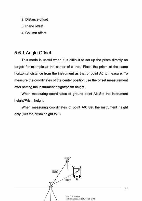
5.6.1 Angle OffsetThis mode is useful when it is difficult to set up the prism directly on
target; for example at the center of a tree. Place the prism at the same
horizontal distance from the instrument as that of point A0 to measure. To
measure the coordinates of the center position use the offset measurement
after setting the instrument height/prism height.
When measuring coordinates of ground point AI: Set the instrument
height/Prism height
When measuring coordinates of point A0: Set the instrument height
only (Set the prism height to 0)
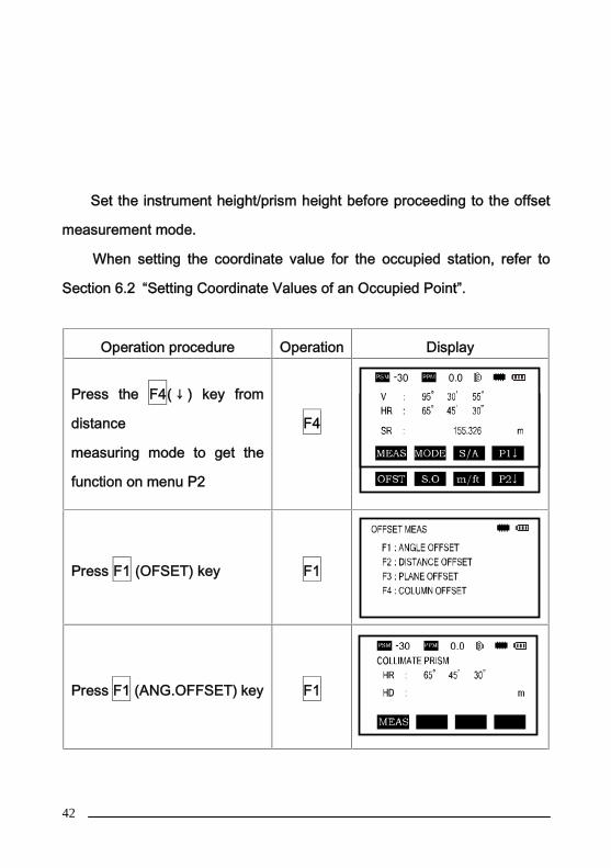
42
Set the instrument height/prism height before proceeding to the offset
measurement mode.
When setting the coordinate value for the occupied station, refer to
Section 6.2 “Setting Coordinate Values of an Occupied Point”.
Operation procedure Operation Display
Press the F4( ↓ ) key from
distance
measuring mode to get the
function on menu P2
F4
Press F1 (OFSET) key F1
Press F1 (ANG.OFFSET) key F1

43
Collimate prism P, and pressthe F1(MEAS) key.The horizontal distance fromthe instrument to the prismwill be measured.
Collimate
[P]
F1
Collimate point AO using thehorizontal motion clampand horizontal tangent screw.
Collimate
AO
Show the north coordinate,east coordinate and zcoordinate of waitedmeasuring point by pressing
key.
To return to procedure 3, press F4 (NEXT) key
To return to the previous mode, press ESC key
5.6.2 Distance Offset MeasurementMeasuring the distance and coordinate of a pond or a tree of which the
radius is known. Measuring the distance or coordinate to P0 point, input
oHD value as an offset value and measure P1 point as shown in the

44
drawing. The display shows distance or coordinate value to P0 point.
When setting the coordinate value for the occupied station, refer to Section
6.2 ‘Setting Coordinate of Occupied Point’
Operation procedure Operation Display
①Press the F4 (↓) key from
distance measuring mode to
get the function on menu P2
F4
②Press F1 (OFSET) key. F1
③ Press F2 (DIST OFSET)
key, enter the measurement
of DIST.OFFSET
F2
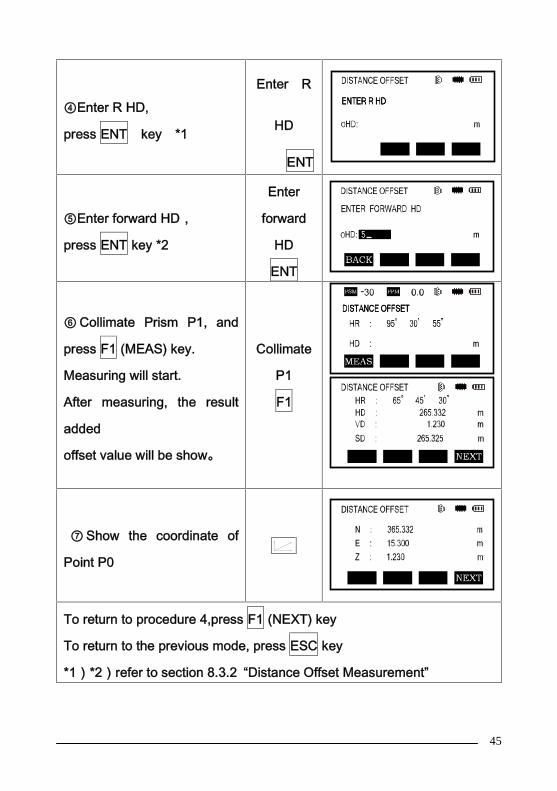
45
④Enter R HD,
press ENT key *1
Enter R
HD
ENT
⑤Enter forward HD,
press ENT key *2
Enter
forward
HD
ENT
⑥ Collimate Prism P1, and
press F1 (MEAS) key.
Measuring will start.
After measuring, the result
added
offset value will be show。
Collimate
P1
F1
⑦ Show the coordinate of
Point P0
To return to procedure 4,press F1 (NEXT) key
To return to the previous mode, press ESC key
*1)*2)refer to section 8.3.2 “Distance Offset Measurement”

46
5.6.3 Plane Offset MeasurementUsed to facilitate distance or coordinate measuring for a given plane.
Three random prism points (P1, P2, P3) on a plane will be measured at first
in the plane-offset measurement to determine the measured plane.
Collimate the measuring target point (P0) then the instrument will calculate
and display coordinate and distance values of the cross point between
collimation axis and the plane.
When setting the coordinate value for the occupied station, refer to Section
7.2 ‘Setting Coordinate Value of Occupied Point’.
Operation procedure Operation Display
①Press the F4 (↓) key from
distance
measuring mode to get the
function on page 2.
F4
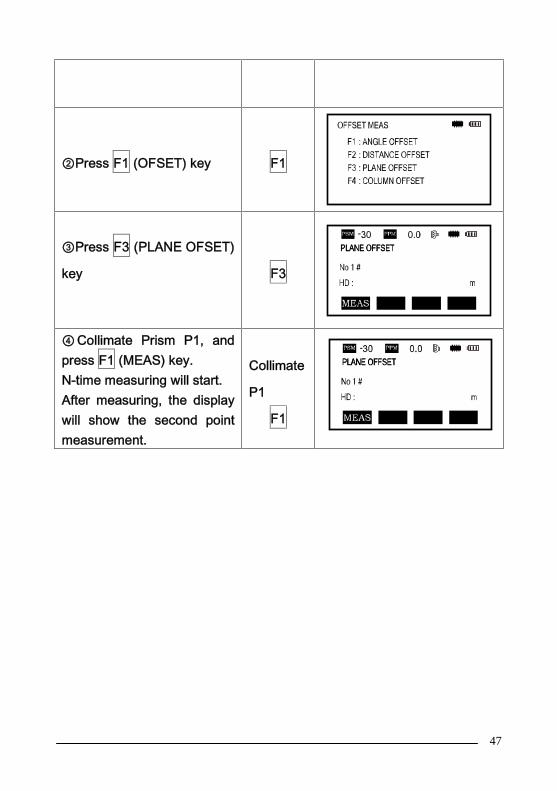
47
②Press F1 (OFSET) key F1
③Press F3 (PLANE OFSET)
key F3
④ Collimate Prism P1, andpress F1 (MEAS) key.N-time measuring will start.After measuring, the displaywill show the second pointmeasurement.
Collimate
P1
F1

48
⑤Measure the second and
third points in the same way.
The instrument calculates
and displays coordinate and
distance values of the cross
point between the collimation
axis and of the plane *1*2
Collimate
P2
F1
Collimate
P3
F1
⑥Collimate the edge (P0) of
the plane *3*4
Collimate
P0
⑦ By pressing keyeach time , horizontaldistance, relative elevationand slope distance areshown in sequence.To show the coordinate ofthe point (P0), presskey.

49
*1 ) In case the calculation of plane was not successful by the measured
three points, error displays. Start measuring over again from the first point.
*2 ) Data display is the mode beforehand of offset measurement mode.
*3 ) Error will be displayed when collimated to the direction which does not
cross with determined plane.
*4 ) The reflector height of the target point P0 is set to zero automatically.
5.6.4 Column Offset MeasurementIf it is possible to measure circumscription point (P 1) of Column
directly the distance to the center of the column (P0), coordinate and
direction angle can be calculated by measured circumscription points (P2)
and (P3).
The direction angle of the center of the column is 1/2 of total direction
angle of circumscription points (P2) and (P3).

50
When setting the coordinate value for the occupied station, refer to
Section 6.2 ‘Setting Coordinate Values of Occupied Point’.
Operation procedure Operation Display
Press the F4 (↓) keyfrom distancemeasuring mode to getthe function on menu P2
F4
Press F1 (OFSET) key F1
Press F4 (COLUMN
OFFSET)keyF4
Collimate the center ofthe column(P1) and press F1(MEAS) keyN-time measuring willstart.After the measurement,angle-measuring displayof the left side (P2) willbe shown.
Collimate
P1
F1

51
Collimate the left side of
column(P2) and press
F4 (SET) key.
After measurement,
angle measuring
display of the right side
(P3) will be shown.
Collimate
P2
F4
⑥Collimate the right sideof the column (P3) andpress F4 (SET) key.After measurement, thedistance between theinstrument and thecenter of column (P0) willbe calculated.
Collimate
P3
F4
To show the coordinate
of point P0,press
key. *1*2
*1)To return to procedure 5, press F4 (NEXT) key
*2)To escape the measuring,press ESC key,the display returns to the
previous mode.

52
6. COORDINATE MEASUREMENT
6.1 Execution of Coordinate MeasurementMeasure the coordinates by entering the instrument height and prism
height, coordinates of unknown Point will be measured directly.
* When setting coordinate values of occupied point, see Section 6.2
“Setting Coordinate Values of Occupied Station Point”.
* When setting the instrument height and prism height, see Section 6.3
“Setting Height of the Instrument” and 6.4 “Setting Height of Target (prism
Height)”.
* To set backsight, determine the backsight azimuth or check the
known azimuth, coordinate and distance.
The coordinates of the unknown point are calculated as shown below and
displayed:
Coordinates of occupied point:(N0,E0,Z0)
Instrument height :INS.HT
Prism height: R.HT
Vertical distance (Relative elevation):Z(VD)
Coordinates of the center of the prism, originated from the center point
of the instrument:(n,e,z)
Coordinates of unknown point:(N1,E1,Z1)
N1=N0+n
E1=E0+e
Z1=Z0+INS.HT+Z-R.HT
Center point of the instrument (N0, E0, Z0+INS.HT)
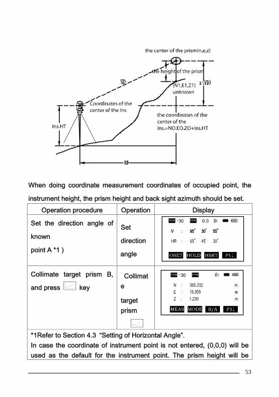
53
When doing coordinate measurement coordinates of occupied point, the
instrument height, the prism height and back sight azimuth should be set.Operation procedure Operation Display
Set the direction angle of
known
point A *1 )
Set
direction
angle
Collimate target prism B,
and press keyCollimat
e
targetprism
*1Refer to Section 4.3 “Setting of Horizontal Angle”.In case the coordinate of instrument point is not entered, (0,0,0) will beused as the default for the instrument point. The prism height will be

54
calculated as 0 when the prism height is not set.
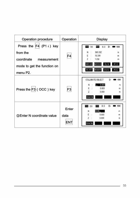
6.2 Setting Coordinate Values of Occupied PointSet the coordinates of the instrument (occupied point) according to
known values and the instrument automatically converts and displays the
unknown point (prism point) coordinates following the observation.
The instrument retains the coordinates of the occupied point after
turning the power off.
55
Operation procedure Operation Display
Press the F4 (P1↓) key
from the
coordinate measurement
mode to get the function on
menu P2.
F4
Press the F3(OCC)key F3
③Enter N coordinate value
Enter
data
ENT
56
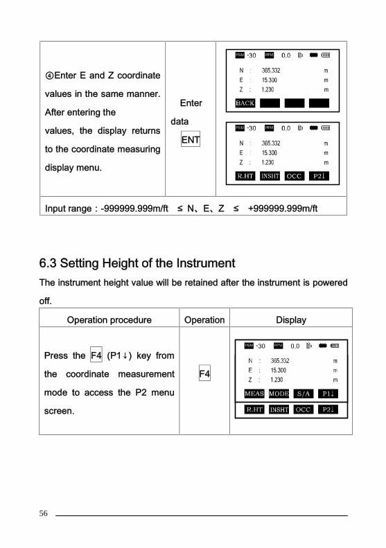
④Enter E and Z coordinate
values in the same manner.
After entering the
values, the display returns
to the coordinate measuring
display menu.
Enter
data
ENT
Input range:-999999.999m/ft ≤ N、E、Z ≤ +999999.999m/ft
6.3 Setting Height of the InstrumentThe instrument height value will be retained after the instrument is powered
off.
Operation procedure Operation Display
Press the F4 (P1↓) key from
the coordinate measurement
mode to access the P2 menu
screen.
F4
57
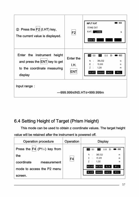
② Press the F2 (I.HT) key,
The current value is displayed.F2
Enter the instrument height
and press the ENT key to get
to the coordinate measuring
display
Enter the
I.H.
ENT
Input range:
—999.999≤INS.HT≤+999.999m
6.4 Setting Height of Target (Prism Height)This mode can be used to obtain z coordinate values. The target height
value will be retained after the instrument is powered off.
Operation procedure Operation Display
Press the F4 (P1↓) key from
the
coordinate measurement
mode to access the P2 menu
screen.
F4
58
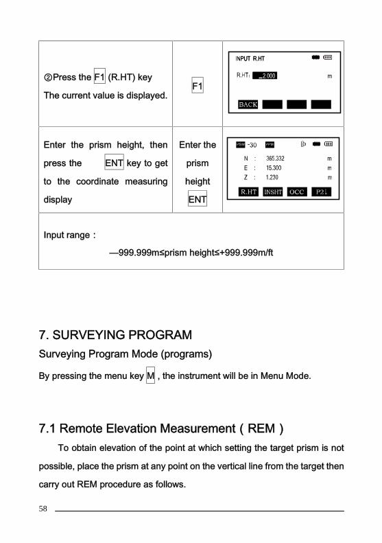
②Press the F1 (R.HT) key
The current value is displayed.F1
Enter the prism height, then
press the ENT key to get
to the coordinate measuring
display
Enter the
prism
height
ENT
Input range:
—999.999m≤prism height≤+999.999m/ft
7. SURVEYING PROGRAMSurveying Program Mode (programs)
By pressing the menu key M , the instrument will be in Menu Mode.
7.1 Remote Elevation Measurement(REM)To obtain elevation of the point at which setting the target prism is not
possible, place the prism at any point on the vertical line from the target then
carry out REM procedure as follows.

59
1)With prism height (h) input
Operation procedure Operation Display
Press the M Key M

60
Press the F2 key , enter
MEAS PROGRAM. menuF2
③Press the F1(REM)key F1
④Press the F1 key F1
⑤Enter prism height (1.3 is
an example in meters)
F1Enterprismheight
1.3F4
⑥Collimate prismCollimate
Prism
⑦ Press the F1 (MEAS)
key, measurement starts.F1

61
Horizontal distance (HD)
between the instrument and
prism will be shown.
⑧Press the F4 (SET)
The prism position will be
decided.
F4
⑨ Collimate target K.
Vertical distance
(VD) will be shown.
Collimate
K
To return to procedure 5,press F2 (R.HT) key.
To return to procedure 6,press F3 (HD) key.
To return to PROGRAMS Menu, press the ESC key.
2)Without prism height input
Operation procedure Operation Display

62
Press the M menu key M
Press the F2 key,enter the
measure programs menu.F2
③Press the F1 (REM) Key. F1
④ Press the F2 key to
select the mode without
prism height.
F2
Collimate prism, press theF1 (MEAS) key. Measuringstarts. Horizontal distance(HD) between theinstrument and target will beshown..
Collimate
target

63
⑥Press the F4 (SET)
The target position will be
decided.
F4
Collimate ground point G ,
press the F4 (SET) key.
The position of
point G will be decided
F4
Collimate target K
Vertical distance (VD) will
be shown
Collimate
K
To return to procedure 5, press the F3 (HD) key.
To return to procedure 6, press the F2 (V) key.
To return to PROGRAMS Menu, press the ESC key.
7.2 Missing Line Measurement (MLM)Measurement for horizontal distance (dHD) , slope distance
(dVD),elevation (dVR) and horizontal bearing (HR) between two target
prisms.
It is possible to enter the coordinate value directly or calculate from
coordinate data file.
MLM Mode has two modes:

64
1. MLM-1 (A-B, A-C): Measurement A-B, A-C, A-D
2. MLM-2 (A-B, B-C): Measurement A-B, B-C, C-D
It is necessary to set the direction angle of the instrument.
[Example] MLM-1 (A-B, A-C)
Procedure of MLM-2(A-B,B-C)mode is completely the same as that
of MLM-1 mode.
Operation procedure Operation Display
①Press the M menu keyM

65
②Press the F2 key, enter
MEAS PROGRAMSF2
③Press the F2 (MLM) key F2
④Enter file nameEnter file
name
⑤Press ENT key. ENT
⑥Press the F1 key F1

66
⑦ Collimate prism A, and
press the F1 (MEAS) key.
Horizontal distance (HD)
between the instrument and
target A will be shown.
Collimate
A
F1
⑧Press the F4 (SET) key
The position of the target is
confirmed.
F4
⑨ Collimate prism B and
press the F1 (MEAS) key.
Horizontal distance (HD)
between the instrument and
target B will be shown..
Collimate
B
F1
⑩Press the F4 (SET) key
The horizontal
distance(dHD) and relative
elevation (dVD) between
target A and B.
F4
⑾To measure the distance
between points
A and C, press the F4
(NEXT) key*1)
F4

67
⑿ Collimate point C (target
C) and press the F1
(MEAS) key.
Horizontal distance (HD)
between the instrument and
target C will be shown.
Collimate
C
F1
⒀Press the F4 (SET) key.
The horizontal distance
(dHD) and relative elevation
(dvD) between taget A and
C will be shown
F4
⒁To measure the distance
between points
A and D, repeat procedure
12 to 14 *
*To return to Previous mode , press the ESC key.
68
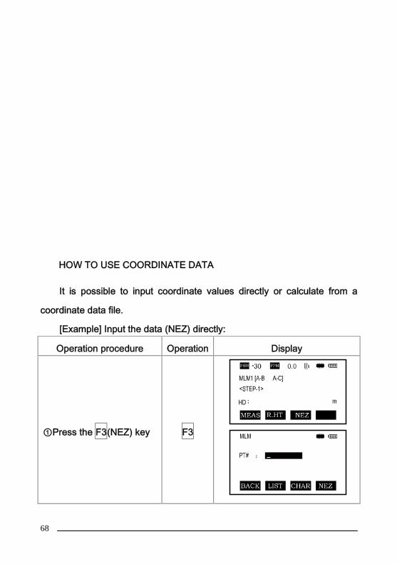
HOW TO USE COORDINATE DATA
It is possible to input coordinate values directly or calculate from a
coordinate data file.
[Example] Input the data (NEZ) directly:
Operation procedure Operation Display
①Press the F3(NEZ) key F3
69
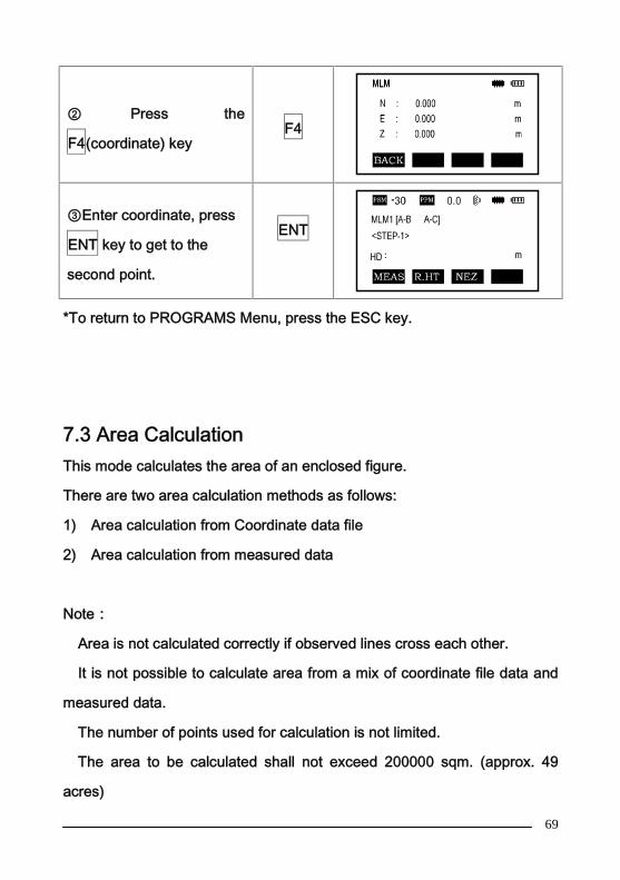
② Press the
F4(coordinate) keyF4
③Enter coordinate, press
ENT key to get to the
second point.
ENT
*To return to PROGRAMS Menu, press the ESC key.
7.3 Area CalculationThis mode calculates the area of an enclosed figure.
There are two area calculation methods as follows:
1) Area calculation from Coordinate data file
2) Area calculation from measured data
Note:
Area is not calculated correctly if observed lines cross each other.
It is not possible to calculate area from a mix of coordinate file data and
measured data.
The number of points used for calculation is not limited.
The area to be calculated shall not exceed 200000 sqm. (approx. 49
acres)

70
1) Area calculation from Coordinate data file
Operation procedure Operation Display
①Press M menu key M
②Press the F2 key, enter
the Measurement Program.F2
③Press F3 (AREA) key F3
Press F1 (FILE DATA) key F1
Enter file name or press F2for LIST. Press ENT key,Initial display will beshown .
Enter
File name
ENT

71
⑥Press F4 (NEXT) keyThe top of the file data(DATA-01) will be set andthe second point numberwill be shown.
F4
Repeat pressing F4(NEXT) key to set requirednumber of the points.When 3 points are set, thearea surrounded by thepoints is calculated and theresult will be shown.
F4
* To set the required point number, press F1 (PT#) key.
* To show the list of the coordinate data in the file, press F2 (LIST) key.
2) Area calculation from measured dataOperation procedure Operation Display
①Press M menu key M
②Press the F2 key, enter
the Measurement Program.F2
72
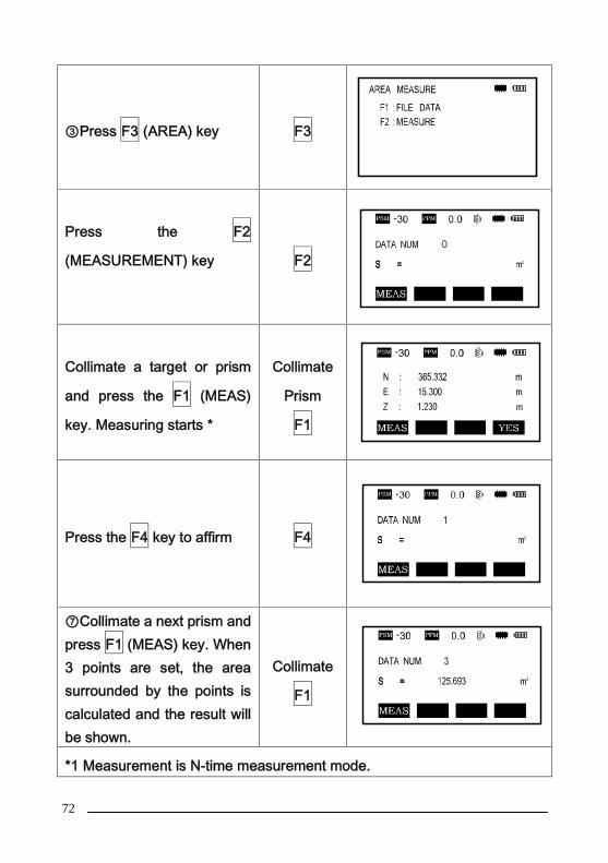
③Press F3 (AREA) key F3
Press the F2
(MEASUREMENT) key F2
Collimate a target or prism
and press the F1 (MEAS)
key. Measuring starts *
Collimate
Prism
F1
Press the F4 key to affirm F4
⑦Collimate a next prism andpress F1 (MEAS) key. When3 points are set, the areasurrounded by the points iscalculated and the result willbe shown.
Collimate
F1
*1 Measurement is N-time measurement mode.

73
7.4 Setting Z Coordinate of Occupied PointOccupied point coordinate data and known point actual measuring data
can be utilized, zcoordinate of occupied point is calculated and reset.
Known point data from a coordinate file can used.
1 ) Setting z coordinate of occupied point
[Example setting] Using coordinate data file
Operation procedure Operation Display

74
①Press the M menu key M
②Press the F2 key ,enter
PROGRAMSF2
③ Press the F4 (Z
COORDINATE keyF4
④ Enter the File Name
then press ENT to affirm.
Input
File Name
ENT
Press the F2 (REF.
MEAS) key and enter the
point number (press F2
for LIST)
F2

75
After input the PT#, press
the ENT key, the
coordinate of this point is
shown.
ENT
⑦Press the F4 (YES) key
to confirm instrument
height setting display will
be shown.
F4
Enter the instrument
height, press ENT key.
Press F1 (MEAS) for
observation results
Enter
INS.HT
ENT
For more information about data file, see chapter 10 “ Memory
Management Mode”.
2)Z coordinate calculation from known point measuring data
[Example setting] Using coordinate data file.
Operation procedure Operation Display
Press the M menu key M

76
Press the F2 key, enter
MEAS PROGRAMS.F2
Press the F4 (Z
COORDINATE) keyF4
Enter the File Name then
press ENT to affirm.
INPUT
File Name
ENT
⑤Press the F2 key F2
⑥Enter the point number
in coordinate data file,
press ENT to affirm.
Enter PT#
ENT
⑦Press the F4 (YES) key
to affirm F4

77
⑧ Enter the height then
press the ENT to affirm.
Enter
R.HT
ENT
⑨Collimate a prism on the
point and press the F1
(MEAS)key.
Measuring starts *1
Collimate
P
F1
⑩Press the F4 (CAL) key
*2
Z: Z coordinate F4
⑾Press the F4 (SET) key
*3
Z coordinate of the
occupied point will be set.
Backsight point masuring
screen will be shown.
F4
⑿Press the F4 (YES) key.Horizontal angle will beset.
F4

78
The display returns toMeasurement Programsmenu.
*1 Measurement is Fine Single measurement mode.
*2 To measure other points, press the F1 (NEXT) key.
*3 Pressing the F1 or F3 key, the display will be changed alternately.
7.5 Point to Line MeasurementThis mode is used to obtain the coordinate data of an unknown
occupied point from a known point and a known line. An observation will
need to be taken at the known point A and along the line N designated for
the example as B. After measuring the 2 points the coordinate and the
direction angle of the instrument will be calculated and recorded.

79
Operation procedure Operation Display
①Press the M menu key M
②Press the F2 key for the
Measure Program menuF2
③Press the ▼key ▼
④ Press F1 (POINT TO
LINE) keyF1

80
⑤Enter instrument height.
Press ENT
Enter
INS.HT
ENT
⑥Enter reflector (PI) height
at point A. Press ENT
Enter
R.HT
ENT
⑦ Collimate prism A
(Origin) and press F1
(MEAS) key.
Measuring starts.* 1
Press F4
Input height of target B
height
will be shown.
Collimate
P1
F1
F4
⑧Enter reflector height of
point B. Press ENT
Enter
INS.HT
ENT
81
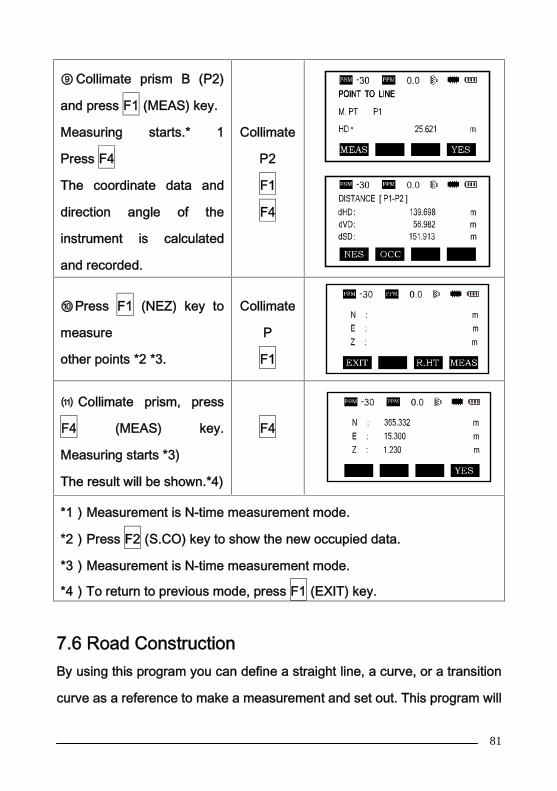
⑨ Collimate prism B (P2)
and press F1 (MEAS) key.
Measuring starts.* 1
Press F4
The coordinate data and
direction angle of the
instrument is calculated
and recorded.
Collimate
P2
F1
F4
⑩Press F1 (NEZ) key to
measure
other points *2 *3.
Collimate
P
F1
⑾ Collimate prism, press
F4 (MEAS) key.
Measuring starts *3)
The result will be shown.*4)
F4
*1)Measurement is N-time measurement mode.
*2)Press F2 (S.CO) key to show the new occupied data.
*3)Measurement is N-time measurement mode.
*4)To return to previous mode, press F1 (EXIT) key.
7.6 Road ConstructionBy using this program you can define a straight line, a curve, or a transition
curve as a reference to make a measurement and set out. This program will
82
do the computation of coordinates and setting out of the design point
according to the stake number and deviation which are defined by the roads
design.
In order to use this program the observation station coordinates and
backsight azimuth angle need to be set.
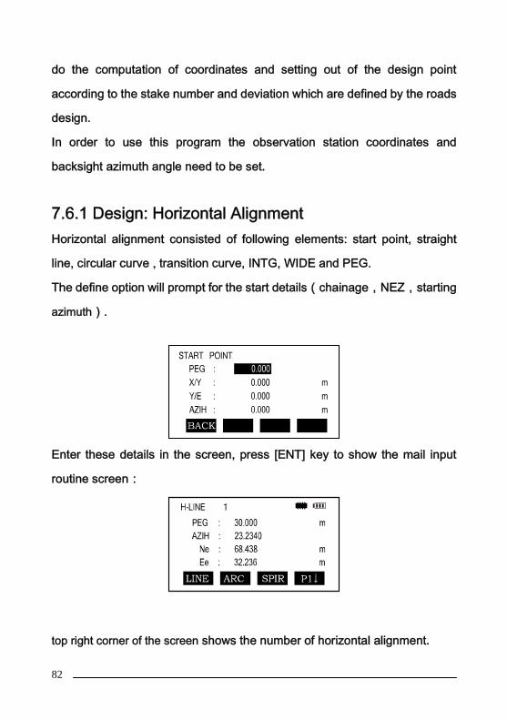
7.6.1 Design: Horizontal AlignmentHorizontal alignment consisted of following elements: start point, straight
line, circular curve , transition curve, INTG, WIDE and PEG.
The define option will prompt for the start details(chainage,NEZ,starting
azimuth).
Enter these details in the screen, press [ENT] key to show the mail input
routine screen:
top right corner of the screen shows the number of horizontal alignment.

83
The main line input screen displays current chainage and the bearing angle
(the tangent line from the chainage) and the function key (For creating new
line). System provides three functions: defining straight line, circular curve,
transition curve. Select a function key, enter the detailed information of the
chainage, the alignment elements will be created. Press ENT key, the new
chainage and bearing angle will be calculated automatically and the main
alignment screen will be restored. Now other line style can be defined, the
new elements can be added only in the end of the original alignment file.
Operation procedure is as follows:
Operation procedure Operatio
n
Display
In main menu, press F2 key
to get MEAS PROGRAM
menu, press F4 key to get
second page of MEAS
PROGRAM menu.
F2
F4
Press F2(ROAD MEASURE)
keyF2
Enter file name, then press
ENT key.F2

84
Press F1(ROAD DESIGN)
key. F1
Press F1(DESIGN H-LINE)
key for the H-line menu.F1
Input starting chainage,northing coordinate, eastingcoordinate and startingazimuth. Press ENT key toshow the main input routinescreen.
Input
starting
data
ENT
In main input routine screen we can add straight line, circular curve and
transition curve to the end of current curve. Select the desired option by
pressing F1-F3 keys.
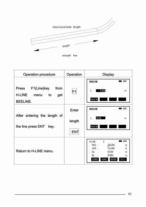
Straight line
When the start point or other line style is well defined it allows you to easily
define a straight line. A straight line length value cannot be negative.
85
Operation procedure Operation Display
Press F1(Line)key from
H-LINE menu to get
BEELINE.
F1
After entering the length of
the line press ENT key.
Enter
length
ENT
Return to H-LINE menu.

86
Circular Curve
Press F2 key (ARC) in the “H-LINE Screen”, the circular curve can be
defined. Circular curves consists of Arc length and the Radius. The radius
value rule: Looking along the forward direction of the curve, when the curve
rotates to right, the radius value is positive. When the curve rotates to left,
the radius value is negative. The arc length cannot be negative.

87
Operation procedure Operation Display
Press F2(ARC) key from
H-LINE menu to get ARC.
F2
Input the radius of the ARC(R) and press the ENT key.Input the length of the ARC(L) and press the ENT key.
Input RENT
INPUT LENT
Return to H-LINE menu
with calculated values.
88
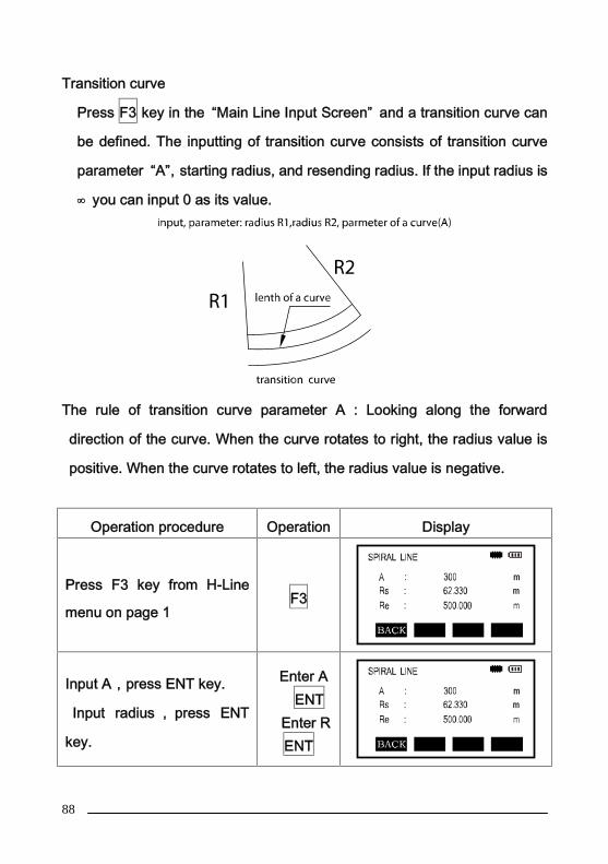
Transition curve
Press F3 key in the “Main Line Input Screen” and a transition curve can
be defined. The inputting of transition curve consists of transition curve
parameter “A”,starting radius, and resending radius. If the input radius is
∞ you can input 0 as its value.
The rule of transition curve parameter A : Looking along the forward
direction of the curve. When the curve rotates to right, the radius value is
positive. When the curve rotates to left, the radius value is negative.
Operation procedure Operation Display
Press F3 key from H-Line
menu on page 1F3
Input A,press ENT key.
Input radius , press ENT
key.
Enter AENT
Enter RENT

89
Instrument returns to
previous mode with solution.
Stake Spacing(INTG)Press F1 (INTG) on the second page of the main alignment screen then
enter into the setting interface of stake spacing interval which needs to be
greater than 0.
Operation procedure Operation Display
Press F4 on the main
alignment screen (1/2) to
enter into the main
alignment screen (2/2)
F4
Press F1 to enter into the
input interface of stakes
space
Enter
space
ENT
Return to the main
alignment screen.
Remarks: the stake spacing can be input only once but can be modified
during editing of the horizontal alignment.

90
Road Widening Stake Number(WIDE)On the second page of the main alignment screen, press F2 (WIDE) to
enter into the road widening stake data input interface, and then input the
stake number of widening point, left road width and right road width.
Operation procedure Operatio
n
Display
Press F4 on the main
alignment screen (1/2) to
enter into the P2 alignment
screen (2/2).
F4
Press F2 (WIDE) to enter
into the input interface of
road widening stake
number.
F2
Input the stake number, left
road width and right road
width, and press ENT to
confirm.
Enter
data
ENT
Remarks: The data of each road widening point will determine the roadwidth between this stake number and next widening point stake number.

91
Additional stake number(PEG)On the second page of the main alignment screen, press F3 (PEG) to enterinto the input interface of addition stake data, and then input the stakenumber of the additional staking point, left road width and right road width.
Operation procedure Operation Display
Press F4 on the main
alignment screen (1/2) to
enter into the main
alignment screen (2/2).
F4
Press F3 (PEG) to enter
into the input interface of
additional stake number.
F3
Input the stake number,
left road width and right
road width, and press
ENT to confirm.
Enter data
ENT
Remarks: Two or more additional stake points can be input.

92
7.6.2 Editing horizontal alignment dataYou can edit the horizontal alignment after input.
From the Road Design Menu select F2: EDIT H-LINE
The function of the soft keys are as follows:
[FST]:Press this key to go to the start of the file,and show the first
alignment data;
[LST]:Press this key to go to the end of the file,and show the last alignment
data;
[EDIT]:To edit the current alignment data;
[SRCH]:Search the alignment data by inputting chainage;
It is possible to edit data by using the above function keys. After entering the
data to be modified press [ENT] key to record the modified data.

93
Operation procedure Operatio
n
Display
Press F2 (Edit horizontal
alignment) on the road design
menu to enter into the
horizontal alignment editing
interface.
F2

94
Through pressing [▲] or [▼],select the alignment data whichis required to be modified, andpress F1 (edit) to edit it, andfinally press ENT (ENTER) toconfirm. *1)
[▲]or[▼]
F1
Enter
data
ENT
Return to the alignmentinterface, the modifiedalignment data will bedisplayed, and then continue tomodify the other alignmentdata as needed
*1 Or press F4 (search), then input the stake number of the alignment
data (chainage) which is required to be modified.
7.6.3 Receiving horizontal alignment

95
You upload a prepared file of horizontal alignment data from a
computer for the alignment work before setting out.
There are two methods to upload data to the instrument.
1. Directly upload the alignment data to the current operating internal
memory from a computer through a data cable (RS-232).
Refer to 10.8 for the operation method
2. Store the alignment data on an SD card, insert the SD card into the
instrument and then copy data from SD card to the memory.
Refer to 10.9 for the operation procedures.
The horizontal alignment data format is in the following format:
Number Data Format Meaning of Parameters
1 start Z,X,Y,aInitial Point: Stake number of initial point Z,
coordinate X, coordinate Y, initial azimuth a
2 Line Lz Straight line data: the length of straight line Lz
3 spiral A,Rs,ReTransition curve data: transition curve parameter A,
radius of initial point Rs, radius of end point Re.
4 arc R,LyCircular curve data: radius of circular curve R, curve
length Ly.
5wide
Zi,wLi,wRi
Widening point data: initiation stake number Zi, width
of left road wLi, width of right road wRi.
6 integer L0 Stake Space: the length of stake space is LO
7 peg Zj,wLj,wRjAdditional stake point data: additional stake number
Zj, left road width wLj, right road width wRj

96
Explanation:
1. The data in the first row is the initial point data, and only one point can be
entered.
2. The data in the second, third, fourth rows is element data, any
combination can be input according to the requirements.
3. The data in the fifth, sixth, and seventh rows is auxiliary calculation data,
choosing whether to enter or not according to the requirements as an option,
the default step length is 20m. Only one staking space is available.
4. The transition curve parameter A and circular curve radius R as needed
(sign as per the direction of route, curve to left is negative, and curve to right
is positive), all other parameters are positive.
5. When the radius of circular curve is ∞, the input radius is 0.
Convert the designed alignment data into *.HAL file using transmission
software, then copy the data to SD card or the memory.
For example:
start 0,2541930.604,502841.293,191.5644
line 452.484
arc 1200,165.885
spiral -90,1e20,130
arc -130,214.928
spiral 110,1e20,280
arc 280,77.151
spiral 110,280,1e20

97
line 100.978
integer 20
wide 0,0,6.5
wide 130.945,1.8,6.5
wide 400,4.5,4.5
wide 1040,0,6.5
peg 130.945,1.8,6.5
peg 220,1.8,0
peg 240,2.338,0
peg 260,2.878,0
peg 1000,4.5,5.28
peg 1020,4.5,6.038
peg 1033.721,4.5,6.48

98
7.6.4 Deleting horizontal alignment dataThe horizontal alignment data in the internal memory can be deleted with
the procedure as follows:
Operation procedure Operation Display
Press F2 (road
measurement) in the menu of
Measurement Program and
choose a file.
F2
Select a
file
ENT
Press F3 (DEL H-LINE
DATA)F3
99
Press F4 (Yes), the current
selected horizontal alignment
data will be deleted.
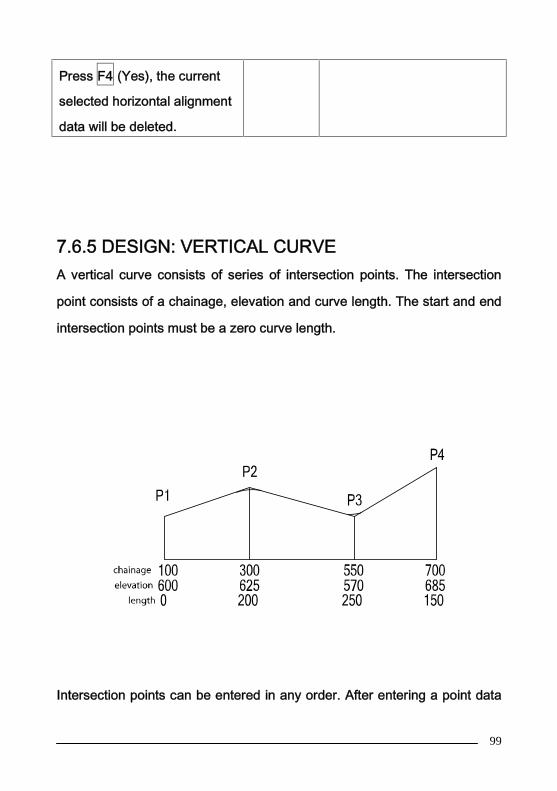
7.6.5 DESIGN: VERTICAL CURVEA vertical curve consists of series of intersection points. The intersection
point consists of a chainage, elevation and curve length. The start and end
intersection points must be a zero curve length.
Intersection points can be entered in any order. After entering a point data

100
press ENT to save it and advance to enter the next point. Press ESC to exit
without saving.
Operation procedure Operation Display
Press F2 key from the menu
to get MEAS PROGRAM.
Press [] for page 2/2
F2
Press F2 ( ROAD
MEASURE)keyF2
Input file name, then press
ENT keyENT
Press F1(ROAD DESIGN)
key F1
Press F3(DESIGN V-LINE)
keyF3
101
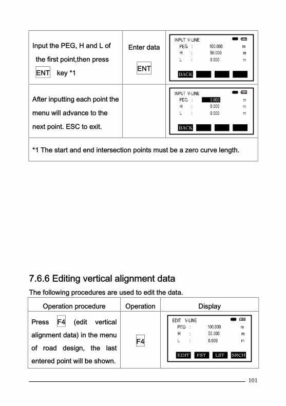
Input the PEG, H and L of
the first point,then press
ENT key *1
Enter data
ENT
After inputting each point the
menu will advance to the
next point. ESC to exit.
*1 The start and end intersection points must be a zero curve length.
7.6.6 Editing vertical alignment dataThe following procedures are used to edit the data.
Operation procedure Operation Display
Press F4 (edit vertical
alignment data) in the menu
of road design, the last
entered point will be shown.
F4

102
Press [▲] or [▼] to select the
alignment data to be
modified. Press F1 (edit) to
edit, and press ENT
(ENTER). *1
[▲]or[▼]
F1
Enter data
ENT
The modified alignment
data will be displayed.
Continue to select data to
modify by using the [▲] or
[▼] keys. ESC to end.
*1Or press F4 (search), then input the stake number of the alignment data
(chainage) which is required to be modified.
7.6.7 Receiving vertical alignment dataThe vertical curve data can be prepared in the office and uploaded to
the instrument to increase efficiency.
There are two methods to upload data to the instrument.
1. Directly upload the alignment data to the current operating internal
memory from a computer through a data cable (RS-232).
Refer to 10.8 for the operation method
103
2. Store the alignment data on an SD card, insert the SD card into the
instrument and then copy the data to memory.
Refer to 10.9 for the operation procedures.
The vertical alignment data format is as follows:
Stake number, elevation, length
Note: The length of the initial point and end point must be 0.
For example:
1015.600,30.000,0.000
1325.000,60.000,200.000
1632.000,27.000,315.000
1900.000,33.000,0.000
Convert the designed alignment data into *.VCL file using transmission
softwave. Then copy the data to SD card or the memory.
Note: keep the text file and work file names consistant.
7.6.8 Deleting vertical alignment dataThe vertical alignment data in the internal memory can be deleted as
follows:
Operation procedure Operatio
n
Display

104
On measurement
procedure menu, press F2
(road measurement) and
choose a file.
F2
Select a
file
ENT
Press F4 (DEL V-LINE
DATA)F4
Press F4 (YES), the
selected vertical alignment
data will be deleted.
7.6.9 Generating a road coordinate fileAfter finishing the operation of vertical and horizontal alignment you
can output a coordinate file *.PTS to memory.

105
The operation procedure is as follows:
Operation procedure Operation Display
In the ROAD DESIGN
menu press [▼] for menu
P2.
[▼]
Press F1 (CAL AND
SAVE COORDINATE TO
FILE), the coordinate file
*.PTS will be created.
F1
7.6.10 Road setting out procedures
For the road setting out program the line of the road must be defined.
Horizontal and vertical alignment can be done according to the procedures
in the previous sections. If vertical data is not required it can be ignored.
106
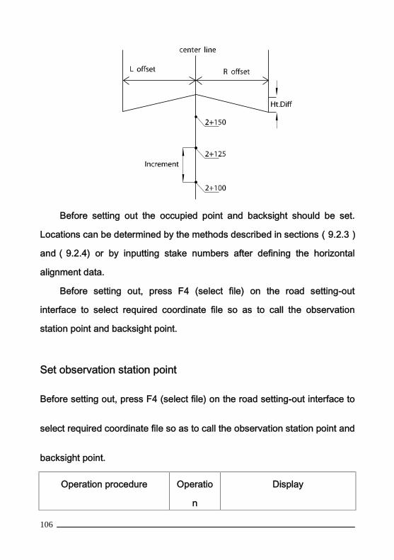
Before setting out the occupied point and backsight should be set.
Locations can be determined by the methods described in sections(9.2.3)
and(9.2.4) or by inputting stake numbers after defining the horizontal
alignment data.
Before setting out, press F4 (select file) on the road setting-out
interface to select required coordinate file so as to call the observation
station point and backsight point.
Set observation station point
Before setting out, press F4 (select file) on the road setting-out interface to
select required coordinate file so as to call the observation station point and
backsight point.
Operation procedure Operatio
n
Display
107
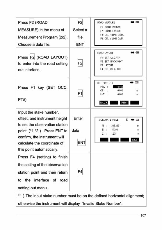
Press F2 (ROAD
MEASURE) in the menu of
Measurement Program (2/2).
Choose a data file.
F2
Select a
file
ENT
Press F2 (ROAD LAYOUT)to enter into the road settingout interface.
F2
Press F1 key (SET OCC.
PT#)F1
Input the stake number,offset, and instrument heightto set the observation stationpoint. (*1,*2). Press ENT toconfirm, the instrument willcalculate the coordinate ofthis point automatically.
Enter
data
ENT
Press F4 (setting) to finish
the setting of the observation
station point and then return
to the interface of road
setting out menu.
F4
*1)The input stake number must be on the defined horizontal alignment;
otherwise the instrument will display “Invalid Stake Number”.

108
*2)Pressing F3 (PT#), you can set the station point from an existing point
or by manually entering coordinate values (9.2.3).
Set backsight point
Operation procedure Operatio
n
Display
Press F2 (ROAD LAYOUT)
in menu 2/2 of ROAD
MEASURE.
F2
Select a
file
ENT
Press F2 (ROAD LAYOUT)
keyF2
Press the F2 ( SET
BACKSIGHT) keyF2
Input the stake number and
deviation (offset) to set the
backsight point. (*1,*2,*3).
Press ENT to confirm and
the instrument will calculate
Enter
data
ENT

109
the coordinate of this point
automatically.
Press F4 (setting) to finish
the setting of the backsight
point and the instrument will
calculate the backsight
azimuth angle automatically.
F4
Sighting the backsight point,
press F4 (YES) to finish the
backsight point setting, and
then the instrument will
configure horizontal circle
automatically according to
azimuth angle.
F4
*1)The input stake number must be on the defined horizontal alignment;
otherwise, it will display “Invalid Stake Number”.
*2)Pressing F3 (PT#), you can set the station point from an existing point
or by manually entering coordinate values (9.2.3).
*3)The deviation is defined as the distance from offset point to center line.
Road setting outNote:
Offset left: the horizontal distance from the left stake point to the center
line.
Offset right: the horizontal distance from the right stake point to the center
110
line.
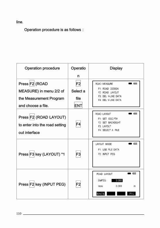
Operation procedure is as follows:
Operation procedure Operatio
n
Display
Press F2 (ROAD
MEASURE) in menu 2/2 of
the Measurement Program
and choose a file.
F2
Select a
file
ENT
Press F2 (ROAD LAYOUT)
to enter into the road setting
out interface
F4
Press F3 key (LAYOUT) *1 F3
Press F2 key (INPUT PEG) F2
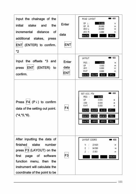
111
Input the chainage of the
initial stake and the
incremental distance of
additional stakes, press
ENT (ENTER) to confirm.
*2
Enter
data
ENT
Input the offsets *3 and
press ENT (ENTER) to
confirm.
EnterdataENT
Press F4 (P↓) to confirm
data of the setting out point.
(*4,*5,*6).
F4
After inputting the data offinished stake numberpress F3 (LAYOUT) on thefirst page of softwarefunction menu, then theinstrument will calculate thecoordinate of the point to be
F3
112
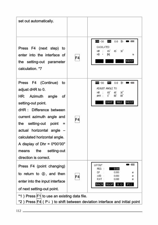
set out automatically.
Press F4 (next step) to
enter into the interface of
the setting-out parameter
calculation. *7
F4
Press F4 (Continue) to
adjust dHR to 0.
HR: Azimuth angle of
setting-out point.
dHR: Difference between
current azimuth angle and
the setting-out point =
actual horizontal angle –
calculated horizontal angle.
A display of Dhr = 0º00’00"
means the setting-out
direction is correct.
F4
Press F4 (point changing)
to return to ④, and then
enter into the input interface
of next setting-out point.
F4
*1)Press F1 to use an existing data file.*2)Press F4(P↓)to shift between deviation interface and initial point
113
input interface.*3) The deviation value of left stake is negative, and the deviation valueof right stake is positive.*4)On the second page, press F2 (Left) F3 (Right) to switch over amongleft stake, center line stake and right stake.*5)On the second page, press F2 (Increase), F3 (Decrease) to switchover between different stake numbers.*6)By pressing [▲]or[▼], you can input the deviation, height difference,and elevation of the same stake number manually.*7)Press F1 (Record) to keep the coordinate of setting-out point.
7.6.11 Slope setting-out
Slope setting-out can be performed as part of the Alignment setout option.
After defining the vertical curve and horizontal alignment in the “Define
Roads Menu” it is possible to perform slope setting-out. Press the F2
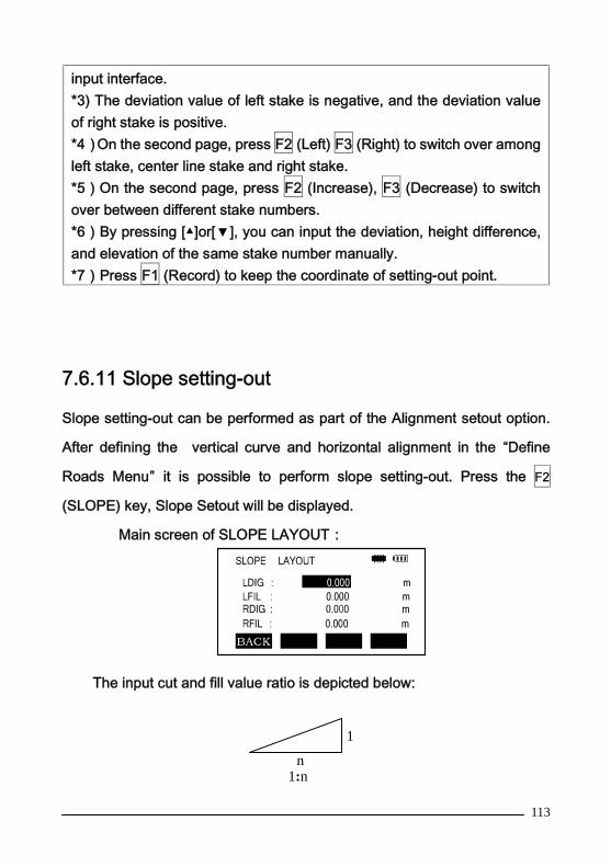
(SLOPE) key, Slope Setout will be displayed.
Main screen of SLOPE LAYOUT:
The input cut and fill value ratio is depicted below:
1
n1:n
114
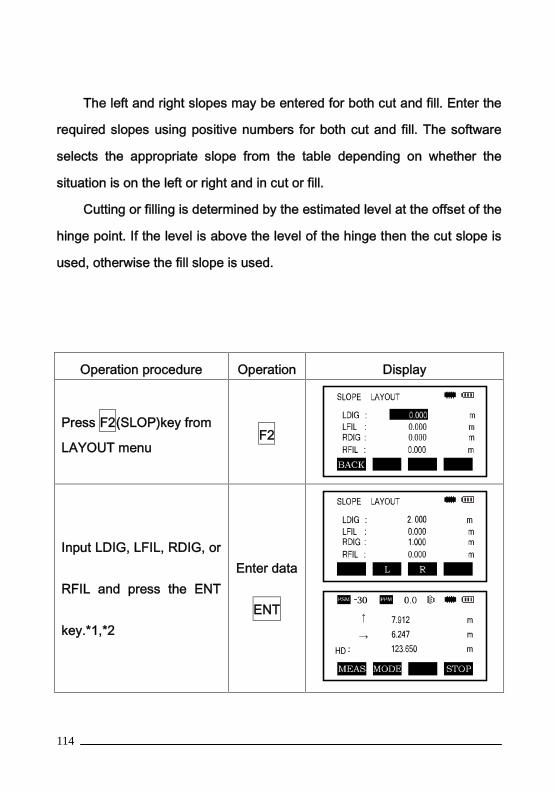
The left and right slopes may be entered for both cut and fill. Enter the
required slopes using positive numbers for both cut and fill. The software
selects the appropriate slope from the table depending on whether the
situation is on the left or right and in cut or fill.
Cutting or filling is determined by the estimated level at the offset of the
hinge point. If the level is above the level of the hinge then the cut slope is
used, otherwise the fill slope is used.
Operation procedure Operation Display
Press F2(SLOP)key from
LAYOUT menuF2
Input LDIG, LFIL, RDIG, or
RFIL and press the ENT
key.*1,*2
Enter data
ENT

115
Turn the instrument andmeasure. When the datadisplayed in [→] and [↑] is0, the setting out point iscorrect.
F1
To return to the previous
mode press the ESC keyESC
Note:*1) An intersection can not be computed if the ground surfacepasses through the hinge point.
*2)The cut is not displayed because the cut at the computed point is zero.
7.7 Stake Out
Please refer to Chapter 9 (LAYOUT) for specific operation procedures.
7.8 Resection
Resection will determine an unknown instrument position using a
maximum of 7 known coordinates and measurement data.
Specific operation procedures are in section 9.4.2 (Resection)

116
8. DATA COLLECTIONData collect menu operation:

117
The total station stores measured data in internal memory or SDcard.
The internal memory is shared by the measured data and thecoordinate data files.
Measured data:
The collected data is organized into files and you can save measured
original data and coordinate data together.
1)When turning the instrument off always have the instrument display on
the main menu or angle measurement screen. This ensures completion of
the memory access process and avoids possible damage to the stored
data.
2)It is recommended to use fully charged batteries to facilitate data
collection whenever possible.
118
8.1 Operation procedure
1. Select a Data Collection File to save data to.
* You should first go to menu 2/2 of the GATHER DATA menu, select F2
(CONFIG) and select “YES” or “NO” in “AUTO SAVE COORD.”
2. Select a Coordinate Data file .
3. Set occupied Point including Instrument Height, Point Number and
Coordinate.
4. Set Backsight Point, Direction and Azimuth.
5. Set PT#, PCODE and R.HT ,start collecting and saving data.
8.2 Preparation
8.2.1 Selecting a File for Data CollectionThe file used by data collection mode must be selected first.
And a selection from data collection menu is possible in the mode.
Operation procedure Operation Display

119
①Press the M key M
② Press F1 (GATHER
DATA) keyF1
③Press F2 (LIST) key to
display the list of files *1F2
④ Scroll the file list by
pressing [▲]or [▼] key,
and select a file. (*2,*3)
[▲]or[▼]
Press the (ENT) key.
The file will be set and
the GATHER DATA 1/2
menu will be shown.
F4

120
*1)If you want to make a new file or input a file name directly enter a file
name and press ENT.
*2)When a file has been already selected, a “*” mark is indicated on left
of the current file name
*3)To seach data use the [▲]or [▼] keys to select a file and press the F1
(SRCH) key.
8.2.2 Selecting a Coordinate File for Data Collection
Operation procedure Operation Display
①Press the F4 (SELECT A
FILE) key from the
GATHER DATA menu 1/2.
F4
② Press the F2 (COORD
DATA) keyF2
③Press the F2(LIST)key F2

121
④Pressing [▲]or [▼] key to
select a file press ENT to
return to GATHER DATA
menu 1/2.
ENT
8.2.3 Occupied Point and Backsight Point
The occupied point coordinates and the direction angle in the data
collect mode are linked with the occupied point. It is possible to set or
change the occupied point and direction angle from the data collect mode.
Occupied points can be set by two methods:
1) Setting from a known point stored in the internal memory
2) Direct key input
The following three setting methods for backsight point can be
selected:
1)Setting from a known point stored in the internal memory
2)Direct key input of coordinate data
3)Direct key input of setting angle
** The setting of the direction angle can be confirmed by measurement.
Example of establishing the occupied point from known data:
Operation procedure Operatio
n
Display
122
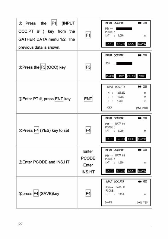
① Press the F1 (INPUT
OCC.PT # ) key from the
GATHER DATA menu 1/2. The
previous data is shown.
F1
②Press the F3 (OCC) key F3
③Enter PT #, press ENT key ENT
④Press F4 (YES) key to set F4
⑤Enter PCODE and INS.HT
EnterPCODE
EnterINS.HT
⑥press F4 (SAVE)key F4
123
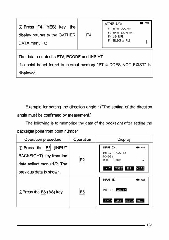
⑦ Press F4 (YES) key, the
display returns to the GATHER
DATA menu 1/2
F4
The data recorded is PT#, PCODE and INS.HT
If a point is not found in internal memory “PT # DOES NOT EXIST” is
displayed.
Example for setting the direction angle:(*The setting of the direction
angle must be confirmed by measement.)
The following is to memorize the data of the backsight after setting the
backsight point from point number
Operation procedure Operation Display
① Press the F2 (INPUT
BACKSIGHT) key from the
data collect menu 1/2. The
previous data is shown.
F2
②Press the F3 (BS) key F3

124
③ Enter backsight point
name *1 , press ENT key ENT
④Press the F4 (YES) key,
collimate the instrument
and press F4 (YES),
INPUT BS will be
displayed.
F4
⑤ Enter PCODE, R.HT as
above . *2
Enter PT #
F4
Press the F4 (MEAS) key F4

125
Collimate back sight point.
Select one of the
measuring modes and
press the soft key.
Example:
F2 (SD) key - measuring
starts. The horizontal circle
is set to calculate direction
angle. The measuring
result is memorized and
the display returns to the
GATHER DATA menu 1/2.
Collimate
F2
*1)Refer to Chapter 1.10 “How to Enter Alphanumeric characters”.
*2)PCODE can be input by inputting a register number linked with the
PCODE library. To show the list in the PCODE library press the F2
(SRCH) key.
If the point is not found in internal memory "PT # DOES NOT EXIST” is
displayed.

126
8.2.4 Measuring and Storing the Data
Operation procedure Operatio
n
Display
①Press the F3 (MEAS) key
from the GATHER DATA
menu 1/2 to measure an
unknown point.
F3
②Press the F1 (INPUT) key
and enter the PT # *1
Press the ENT key
F1
Enter PT
#
ENT
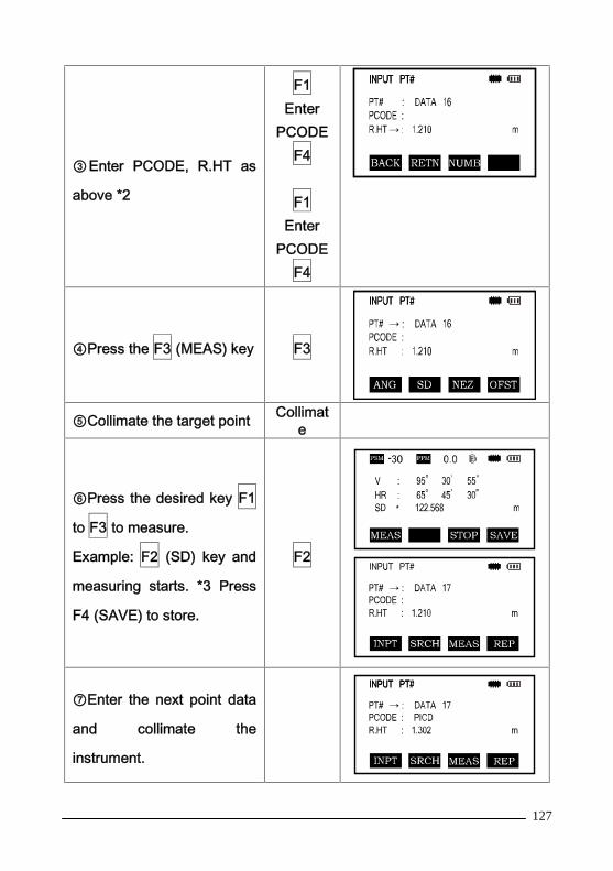
127
③Enter PCODE, R.HT as
above *2
F1Enter
PCODEF4
F1Enter
PCODEF4
④Press the F3 (MEAS) key F3
⑤Collimate the target point Collimate
⑥Press the desired key F1
to F3 to measure.
Example: F2 (SD) key and
measuring starts. *3 Press
F4 (SAVE) to store.
F2
⑦Enter the next point data
and collimate the
instrument.

128
⑧Press F4 (REP) keyMeasuring starts in thesame measuring mode ofthe previous point.Data is recordedContinue the measuring inthe same way. Press ESCto finish GATHER DATAmode.
Collimat
e
F4
*1)Refer to Chapter 1.10 “How to Enter Alphanumeric characters”.*2)PCODE can be input by inputting a register number linked withPCODE library To show the list in the PCODE library, press the F2(SRCH) key.*3)The measurement data will be automatically saved to internalmemory when measure mode ONE FINE is selected.
Searching the recorded data
While executing the GATHER DATA mode you can search the
recorded data.
Operation procedure Operatio
n
Display
① While executing the
GATHER DATA mode, press
F2 (SRCH) key.*1
The file name in use will
F2

129
appear on the top of the right
side of the display.
②Select one of three search
methods by pressing F1 to F3
key *2
F1—F3
*1)It is possible to see the PCODE list when the arrow is located beside
PCODE or ID.
*2 ) The operation is same as the “ SEARCH ” in the MEMORY
MANAGEMENT MODE For more information, refer to Section 10.3
“Searching Data”.
Entering PCODE directly
While executing the Data Collect mode, you can enter PCODE/ID from
PCODE Library.
Operation procedure Operation Display

130
① Move the arrow to
PCODE in the GATHER
DATA mode, press the F1
(INPUT) key
F1
Enter
PCODE
ENT
Entering PCODE from the list of PCODE’s
You also can enter PCODE from the list of PCODE’s.
Operation procedure Operation Display
① Move the arrow to thePCODE in the GATHERDATA mode, press the F2(SRCH) key.
F2
By pressing the followingkeys, the register numberwill increase or decrease.[ ▲ ] or [▼]: Increasing orDecreasing one by one.
[▲]or[▼]

131
Press the F4 (ENT) key F4
*1)To edit the PCODE library, Press the F1 (EDIT) key.
To delete the selected PCODE registered press the F3 (DEL) key,
PCODE can be edited in GATHER DATA menu 2/2 or MEMORY
MANAGEMENT menu 2/3.
8.3 Data Collect Offset Measurement Mode
This mode is useful when it is difficult to set up the prism directly for
example at the center of a tree.
Data Collect Offset Measurement has four measuring methods:
1. Angle Offset Measurement
2. Distance Offset Measurement
3. Plane Offset Measurement
4. Column Offset Measurement
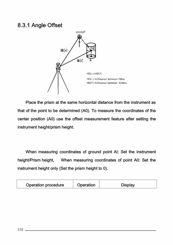
132
8.3.1 Angle Offset
Place the prism at the same horizontal distance from the instrument as
that of the point to be determined (A0). To measure the coordinates of the
center position (A0) use the offset measurement feature after setting the
instrument height/prism height.
When measuring coordinates of ground point AI: Set the instrument
height/Prism height, When measuring coordinates of point A0: Set the
instrument height only (Set the prism height to 0).
Operation procedure Operation Display

133
① Press F3 (MEAS) key
from the GATHER DATA
mode.
F3
②Press F4 (OFST) offset
key.F4
③ Press F1 (ANGLE
OFFSET) key.F1
④ Collimate the prism Collimate P
⑤Press F1 (MEAS) key.
Continuous measuring
starts, display HR, HD, VD
and SD of aim point.
F1
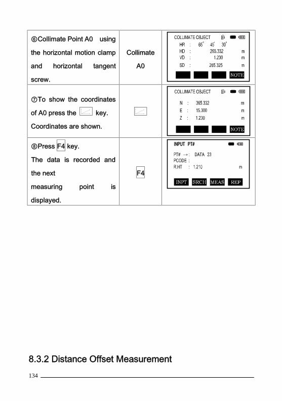
134
⑥Collimate Point A0 using
the horizontal motion clamp
and horizontal tangent
screw.
Collimate
A0
⑦To show the coordinates
of A0 press the key.
Coordinates are shown.
⑧Press F4 key.
The data is recorded and
the next
measuring point is
displayed.
F4
8.3.2 Distance Offset Measurement

135
Obtaining coordinates of a point using a distance offset can be
achieved as follows:
Operation procedure Operatio
n
Display
① Press F3 (MEAS) key
from the GATHER DATA
mode.
F3
②Press F4 (OFST) key. F4

136
③ Press F2 (DISTANCE
OFFSET) keyF2
④ Enter Right and Left
direction offset value (offset
left is negative)
Press ENTkey.
Enter HD
ENT
⑤ Enter Forward direction
offset value. (offset towards
the front is negative). Press
ENT key.
EnterForwarddirection
offsetvalueENT
⑥Collimate the Prism P and
press F1, display HR, HD,
VD and SD of aim point and
add offset correction.
F1
Enter HD
F4
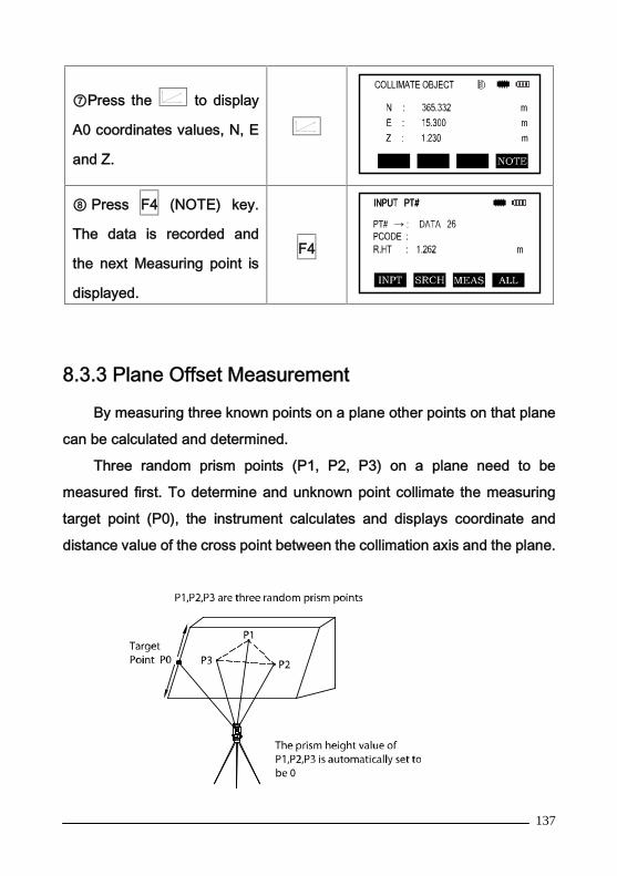
137
⑦Press the to display
A0 coordinates values, N, E
and Z.
⑧ Press F4 (NOTE) key.
The data is recorded and
the next Measuring point is
displayed.
F4
8.3.3 Plane Offset Measurement
By measuring three known points on a plane other points on that plane
can be calculated and determined.
Three random prism points (P1, P2, P3) on a plane need to be
measured first. To determine and unknown point collimate the measuring
target point (P0), the instrument calculates and displays coordinate and
distance value of the cross point between the collimation axis and the plane.

138
When setting the coordinate value for the occupied station, refer to
Section 6.2 “Setting Coordinate Values of Occupied Point”
Operation procedure Operation Display
①Press F3 (MEAS) key
from GATHER DATA
mode.
F3
②Press F4 (0FST) key. F4
③ Press F3 (PLANE
OFFSET) keyF3
④Collimate P1, press F1
(MEAS) key.
Collimat
e P1

139
Measuring will start.
After measuring, the
display will show the
second point
measurement.
F1
⑤ Measure the second
and third points.
The display change to
PT# in the plane offset
measurement screen.
Collimate
P2
F1
Collimate
P3
F1
⑥Collimate the edge (P0)
of the plane *1,*2
Instrument displays V,
HR, HD, VD and SD
Collimate
P0
⑦Press the key to
display P0 coordinates in
N, E and Z.
⑧Press F4 and the data
is recorded. The next
offset point number will be
displayed.
F4

140
*1) If the calculation of the plane was not successful an error will display.
Begin measuring again from the first point.
*2) An error will be displayed when an observation is taken that does not
cross the observed plane.
8.3.4 Column Offset Measurement
If it is possible to measure the circumscription point (P1) of a column,
the distance to the center of the column (P0), coordinate and direction angle
can be calculated by observing circumscription points (P2) and (P3).
The direction angle of the center of the column is the average of the
observed angles of circumscription points (P2) and (P3).
When setting the coordinate value for the occupied station refer to

141
Section 6.2 “Setting
Coordinate Values of Occupied Point”
Operation procedure Operation Display
①Press F3 (MEAS) key
from data collect mode.F3
②Press F4 (0FSET) key. F4
③ Press F4 (COLUMN
OFFSET) keyF4

142
④Collimate the center of
the column (P1) and press
F1 (MEAS) key.
Measuring starts.
After the measurement
the instrument will display
“LEFT” (P2).
F1
⑤Collimate the left side ofthe column (P2) and pressF4 (SET) key. After themeasurement theinstrument will display“RIGHT” (P3).
Collimate
P2
F4
⑥Collimate the right side
of the
column (P3) and press the
F4 key, the display shows
P0, HR, HD, VD and SD.
Collimate
P3
F4
⑦ To show the
coordinates of P0, press
the key.
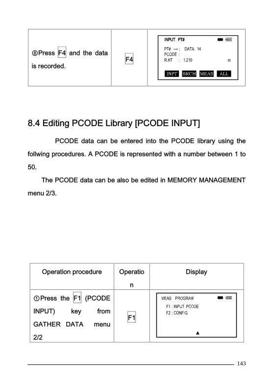
143
⑧Press F4 and the data
is recorded.F4
8.4 Editing PCODE Library [PCODE INPUT]
PCODE data can be entered into the PCODE library using the
follwing procedures. A PCODE is represented with a number between 1 to
50.
The PCODE data can be also be edited in MEMORY MANAGEMENT
menu 2/3.
Operation procedure Operatio
n
Display
①Press the F1 (PCODE
INPUT) key from
GATHER DATA menu
2/2
F1
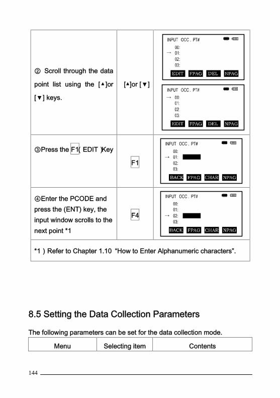
144
② Scroll through the data
point list using the [▲]or
[▼] keys.
[▲]or [▼]
③Press the F1(EDIT)Key
F1
④Enter the PCODE andpress the (ENT) key, theinput window scrolls to thenext point *1
F4
*1)Refer to Chapter 1.10 “How to Enter Alphanumeric characters”.
8.5 Setting the Data Collection Parameters
The following parameters can be set for the data collection mode.
Menu Selecting item Contents
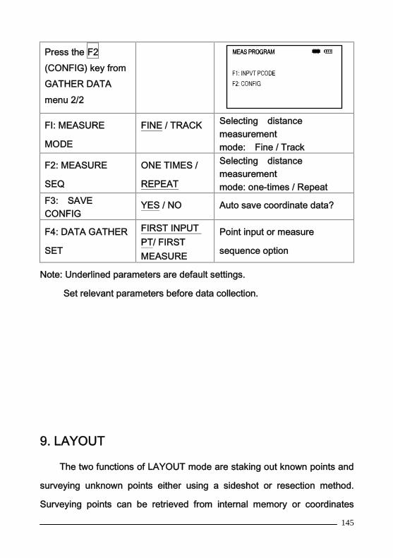
145
Press the F2(CONFIG) key fromGATHER DATAmenu 2/2
FI: MEASURE
MODE
FINE / TRACK Selecting distancemeasurementmode: Fine / Track
F2: MEASURE
SEQ
ONE TIMES /
REPEAT
Selecting distancemeasurementmode: one-times / Repeat
F3: SAVECONFIG
YES / NO Auto save coordinate data?
F4: DATA GATHER
SET
FIRST INPUTPT/ FIRSTMEASURE
Point input or measure
sequence option
Note: Underlined parameters are default settings.
Set relevant parameters before data collection.
9. LAYOUT
The two functions of LAYOUT mode are staking out known points and
surveying unknown points either using a sideshot or resection method.
Surveying points can be retrieved from internal memory or coordinates

146
manually entered into the instrument.. The coordinate data is loaded from a
computer to the internal memory via RS-232C, USB, or SD card.
The coordinate data is stored in a COORD. DATA file.
For the internal memory refer to Chapter 10 "MEMORY
MANAGEMENT MODE"1 ) When turning off the power always have the instrument display on
the main menu screen or main angle measurement mode screen. Failureto have the instrument in these screens could corrupt the stored data if theinstrument is powered off.2 ) It is recommended for safety to fully charge the batteries beforeoperation. Always have a fully charged battery on hand for convenience.3 ) When recording new data always consider the amount of internalmemory available. The SD card port will provide nearly unlimited availablestorage.
9.1 Setting the Parameters of Data Collection
To use the layout procedure mode use the following steps:
1. Select the data file to record the data collected.

147
2. Set the occupied point.
3. Set the backsight point or azimuth angle.
4. Input layout point coordinates and follow menu prompts.
9.2 Preparation
9.2.1 Setting the GRID FACTOR
The Grid Factor can be set in the Parameter Set menu of the CONFIG
options.
9.2.2 Selecting Coordinate Data File
You can execute a Layout from a selected coordinate data file or you
can record new measured data into a selected coordinate data file.
When in LAYOUT MODE the instrument will prompt for a file name.
Operation procedure Operation Display

148
①Press the F1 (SELECT A
FILE) key from the layout
menu 2/2.
F1
②Press the F2 (LIST) key
to display the
list of coordinate data
files.*1
F2
③ Scroll the file list bypressing the [▲]or[▼] keyand select a file to use*2,*3, then press ENT keyto return to LAYOUT(2/2)
[▲]or[▼]
*1)If you want to input file name directly, press the F1 (INPUT)key and
enter a file name.
*2)A file will be highlighted by a indicated on left of the file name.
Press ENT to select.
*3)For the file discrimination mark (*, &,), refer to Section 10.4 “FILE
MAINTENANCE”
9.2.3 Setting Occupied PointOccupied points can be set by two setting methods:
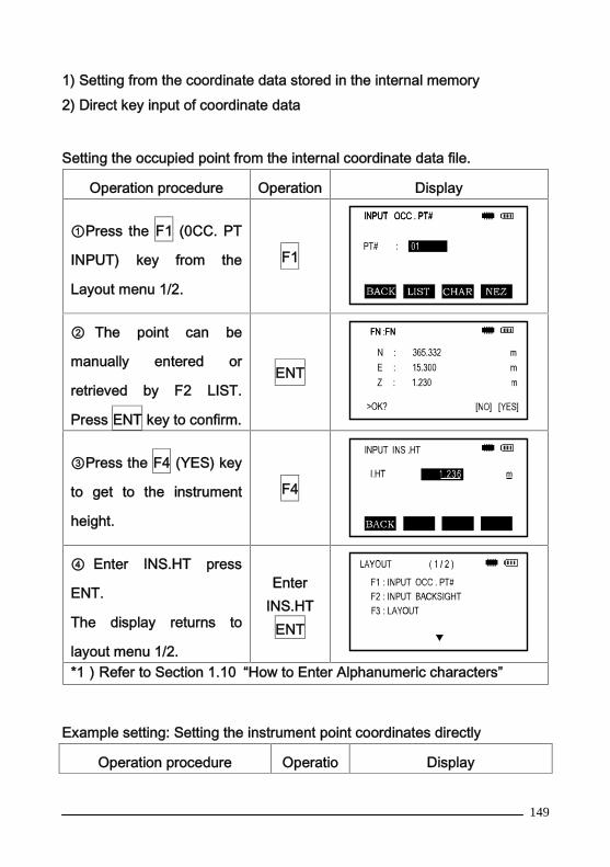
149
1) Setting from the coordinate data stored in the internal memory2) Direct key input of coordinate data
Setting the occupied point from the internal coordinate data file.
Operation procedure Operation Display
①Press the F1 (0CC. PT
INPUT) key from the
Layout menu 1/2.
F1
② The point can be
manually entered or
retrieved by F2 LIST.
Press ENT key to confirm.
ENT
③Press the F4 (YES) key
to get to the instrument
height.
F4
④ Enter INS.HT press
ENT.
The display returns to
layout menu 1/2.
EnterINS.HT
ENT
*1)Refer to Section 1.10 “How to Enter Alphanumeric characters”
Example setting: Setting the instrument point coordinates directly
Operation procedure Operatio Display
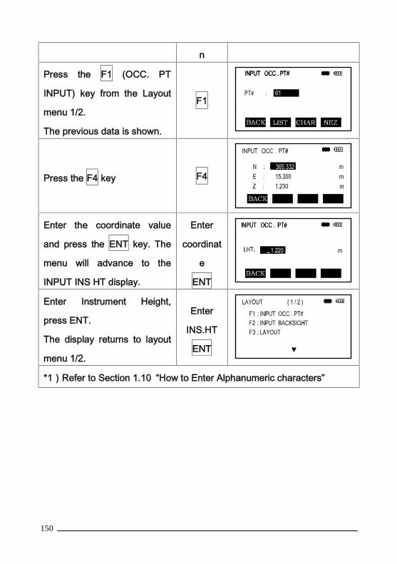
150
n
Press the F1 (OCC. PT
INPUT) key from the Layout
menu 1/2.
The previous data is shown.
F1
Press the F4 key F4
Enter the coordinate value
and press the ENT key. The
menu will advance to the
INPUT INS HT display.
Enter
coordinat
e
ENT
Enter Instrument Height,
press ENT.
The display returns to layout
menu 1/2.
Enter
INS.HT
ENT
*1)Refer to Section 1.10 “How to Enter Alphanumeric characters”

151
9.2.4 Setting Backsight Point
The following three methods for the Backsight point can be used:
1)Setting from the coordinate data file stored in the internal memory.
2)Direct key input of coordinate data.
3)Direct key input of azimuth.
Every press of the F4 key will switch the inputting backsight orientation
angle and inputting coordinate data of backsight point directly.

152
Example setting: Setting the backsight point from the internal coordinate
data file
Operation procedure Operatio
n
Display

153
Press the F2 (BACKSIGHTINPUT) key from the Layoutmenu. F2
Enter PT# or F2 LIST and
select a point *1, press the ENT
key.
Enter
PT#
ENT
Press the F4 (YES) key ,
instrument will calculate
automatically and show the
backsight set display.
F4
Sight the backsight point and
press the
F4 (YES) key. The display
returns to the
layout menu 1/2
Sight BS
F4
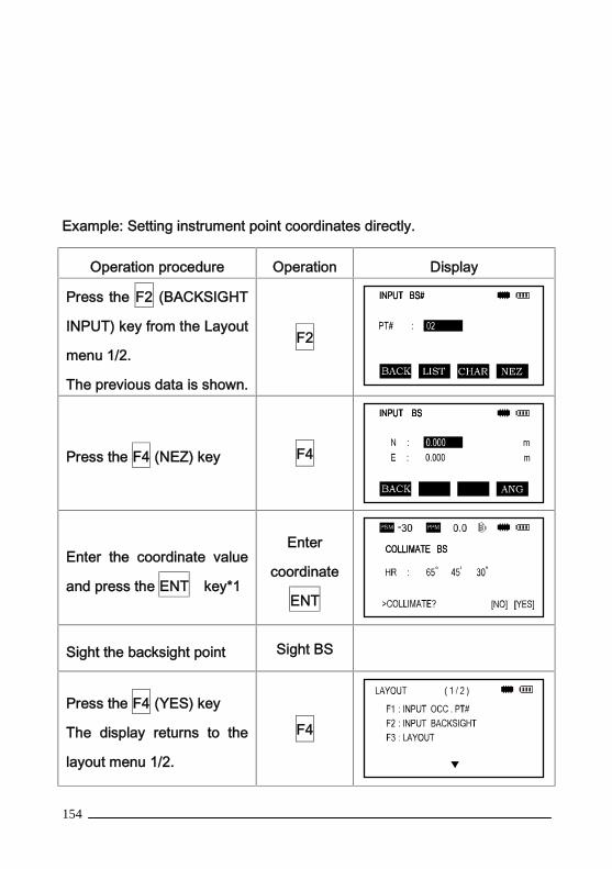
154
Example: Setting instrument point coordinates directly.
Operation procedure Operation Display
Press the F2 (BACKSIGHT
INPUT) key from the Layout
menu 1/2.
The previous data is shown.
F2
Press the F4 (NEZ) key F4
Enter the coordinate value
and press the ENT key*1
Enter
coordinate
ENT
Sight the backsight point Sight BS
Press the F4 (YES) key
The display returns to the
layout menu 1/2.
F4
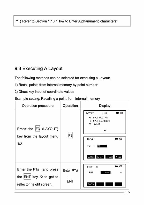
155
*1)Refer to Section 1.10 “How to Enter Alphanumeric characters”
9.3 Executing A Layout
The following methods can be selected for executing a Layout:
1) Recall points from internal memory by point number
2) Direct key input of coordinate values
Example setting: Recalling a point from internal memory
Operation procedure Operation Display
Press the F3 (LAYOUT)
key from the layout menu
1/2.
F3
Enter the PT# and press
the ENT key *2 to get to
reflector height screen.
Enter PT#
ENT

156
Enter the reflector height
and press ENT.
After inputting values the
instrument will calculate
the layout point position.
HR:Calculated horizontal
angle of the layout point
HD:Calculated horizontal
distance from the
instrument to the layout
point.
Enter
R.HT
F4
Press the F4 (NEXT) key .HR : Measured (actual)horizontal angledHR: difference incalculated angle in relationto actual observed angle.Collimate the instrument todHR=0º00’00"
Collimate
Press the F2 (DIST) keyHD : Measuring (actual)horizontal distancedH : Horizontal distanceremaining to the layoutpoint.dZ: Vertical distanceremaining to the layoutpoint.
F2

157
Press the F1(MEAS)key.
The fine mode measuring
starts.
F1
⑦When the display value
dHR, Dhd and DZ
are equal to 0 the layout
point is established *3
Press the F3 (NEZ) key.
The measured coordinate
data is shown to confirm
the value of the layout
point.
F3
Press the F4 (NEXT) key
to set next layout point.F4
*1)Refer to Section 1.10 “How to Enter Alphanumeric characters”
*2)A point number can not be entered when data to comply with thecoordinate value does not exist in the file.*3)Pressing the or ANG keys can switch between the layout angleand distance.

158
9.4 Setting A New Point
New points can be established by the instrument either using a
sideshot or resection method.
9.4.1 Side Shot MethodSet up the instrument at a known point and measure the coordinate of
the new points by the side shot method.
Operation procedure Operation Display
Press the [▼] key from the
layout menu 1/2 to get the
layout menu 2/2.
F4
Press the F2 (NEW POINT)
keyF2
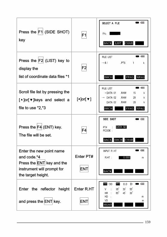
159
Press the F1 (SIDE SHOT)
keyF1
Press the F2 (LIST) key to
display the
list of coordinate data files *1
F2
Scroll file list by pressing the
[ ▲ ]or[▼]keys and select a
file to use *2,*3
[▲]or[▼]
Press the F4 (ENT) key.
The file will be set.F4
Enter the new point nameand code.*4Press the ENT key and theinstrument will prompt forthe target height.
Enter PT#
ENT
Enter the reflector height
and press the ENT key.
Enter R.HT
ENT
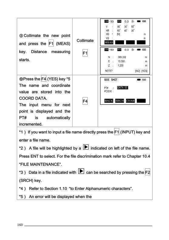
160
⑨ Collimate the new point
and press the F1 (MEAS)
key. Distance measuring
starts.
Collimate
F1
⑩Press the F4 (YES) key *5The name and coordinatevalue are stored into theCOORD DATA.The input menu for nextpoint is displayed and thePT# is automaticallyincremented.
F4
*1) If you want to input a file name directly press the F1 (INPUT) key and
enter a file name.
*2) A file will be highlighted by a indicated on left of the file name.
Press ENT to select. For the file discrimination mark refer to Chapter 10.4
“FILE MAINTENANCE”.
*3) Data in a file indicated with can be searched by pressing the F2
(SRCH) key.
*4) Refer to Section 1.10 “to Enter Alphanumeric characters”.
*5) An error will be displayed when the
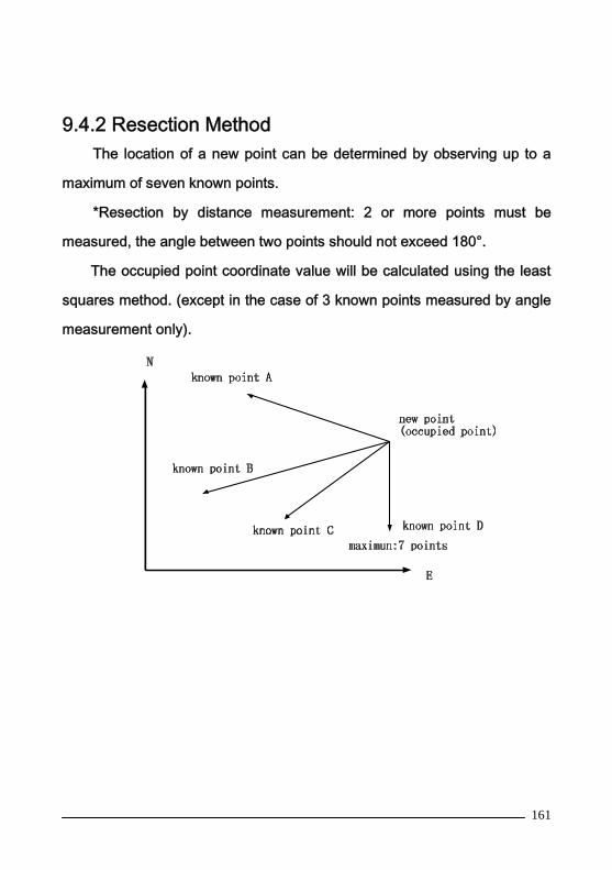
161
9.4.2 Resection MethodThe location of a new point can be determined by observing up to a
maximum of seven known points.
*Resection by distance measurement: 2 or more points must be
measured, the angle between two points should not exceed 180°.
The occupied point coordinate value will be calculated using the least
squares method. (except in the case of 3 known points measured by angle
measurement only).
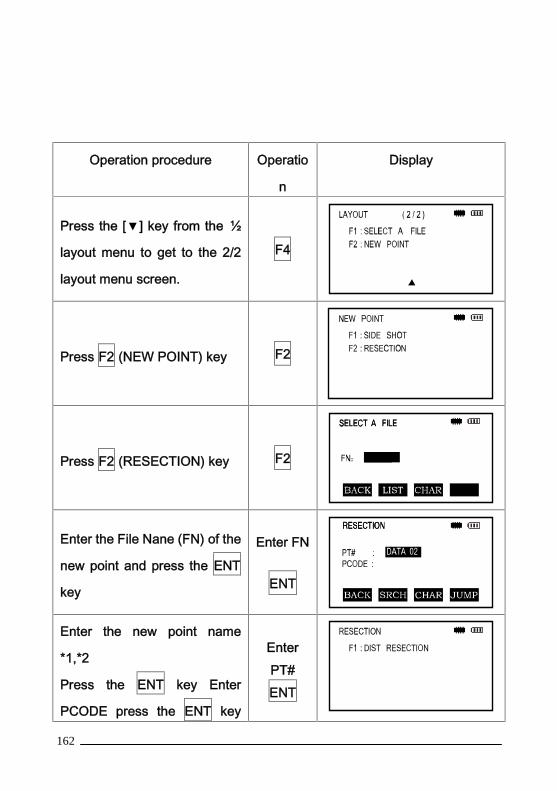
162
Operation procedure Operatio
n
Display
Press the [▼] key from the ½
layout menu to get to the 2/2
layout menu screen.
F4
Press F2 (NEW POINT) key F2
Press F2 (RESECTION) key F2
Enter the File Nane (FN) of the
new point and press the ENT
key
Enter FN
ENT
Enter the new point name
*1,*2
Press the ENT key Enter
PCODE press the ENT key
EnterPT#ENT
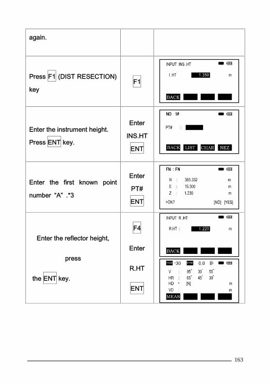
163
again.
Press F1 (DIST RESECTION)
keyF1
Enter the instrument height.
Press ENT key.
Enter
INS.HT
ENT
Enter the first known point
number “A” .*3
Enter
PT#
ENT
Enter the reflector height,
press
the ENT key.
F4
Enter
R.HT
ENT
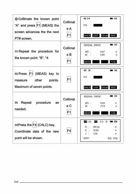
164
⑩Collimate the known point
“A” and press F1 (MEAS) the
screen advances the the next
PT# screen.
Collimat
e A
F1
⑾ Repeat the procedure for
the known point “B”. *4
Collimat
e B
F1
⑿ Press F1 (MEAS) key to
measure other points.
Maximum of seven points.
F1
⒀ Repeat procedure as
needed.
Collimat
e C
F1
⒁Press the F4 (CALC) key.
Coordinate data of the new
point will be shown.
F4

165
⒂Press F4 (YES) key *5
The new point data will be
stored into the coordinate data
file and the value of occupied
coordinate data will change to
that of the calculated new
point.
F4
*1)See Section 1.10 “How to Enter Alphanumeric characters”*2)When there is no need to store the new point data press F3 (SKP) key.*3)To enter the known point coordinate data by directly press F3 (NEZ)key.*4)RESIDUAL ERRORdHD (Horizontal distance between two known points )= Measured Value -Calculated ValuedZ (Z coordinate of the new point calculated from known point A) - (Zcoordinate of the newpoint calculated from Point B )*5)If the F3 (NO) key is pressed the new point data is not stored to thecoordinate data file, only the value of the occupied coordinate datachanges to that of the calculated new point.
View Coordinate Data
You can audit the PT# list and enter data from the list you can also see
the coordinate data of a point.
Operation procedure Operation Display
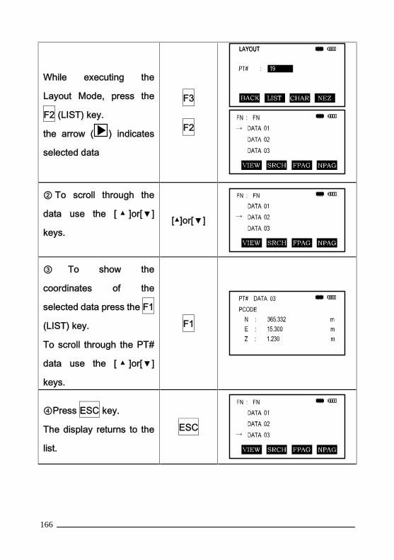
166
While executing the
Layout Mode, press the
F2 (LIST) key.
the arrow ( ) indicates
selected data
F3
F2
② To scroll through the
data use the [ ▲ ]or[▼]
keys.[▲]or[▼]
③ To show the
coordinates of the
selected data press the F1
(LIST) key.
To scroll through the PT#
data use the [ ▲ ]or[▼]
keys.
F1
④Press ESC key.
The display returns to the
list.
ESC

167
⑤Press ENT the key.
The selected point number
is set as the PT# to layout
ENT
F4
10. MEMORY MANAGEMENT MODE
The following internal memory settings are available in this mode:

168
1) MEMORY MEDIUM: Choose the current data storage medium (flash / SD
card)
2) FILE STATE: Checking the number of stored data / Remaining internal
memory capacity.
3) DATA SEARCH: Search the recorded data
4) FILE MAINTAIN: Deleting files / Editing file name
5) INPUT COORDINATE: Inputting coordinate data into coordinate data file
6) DEL COORDINATE: Deleting coordinates from a coordinate data file
7) PCODE INPUT: Inputting PCODE DATA into the PCODE library
8) DATA TRANSFER: Sending measured data or coordinate data or
PCODE Library data / Uploading coordinate data or PCODE library
data/setting
9) FILE OPERATION: Exchange the files of the FLASH memory and SD
CARD with each other.
10) INITIALIZE: Initializing internal memory
Memory manager menu operation:
By pressing the M menu key the instrument will be in MENU 1/2 mode.
Press the F3 (MEMORY MGR) key, the menu of MEMORY MGR 1/3 will be
shown.
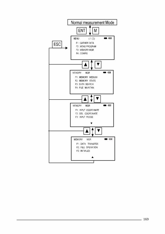
169
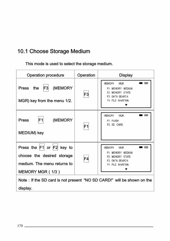
170
10.1 Choose Storage Medium
This mode is used to select the storage medium.
Operation procedure Operation Display
Press the F3 (MEMORY
MGR) key from the menu 1/2.F3
Press F1 (MEMORY
MEDIUM) keyF1
Press the F1 or F2 key to
choose the desired storage
medium. The menu returns to
MEMORY MGR(1/3)
F4
Note:If the SD card is not present “NO SD CARD!” will be shown on the
display.

171
10.2 Display Internal Memory Status
This mode is used to check the internal memory status.
Operation procedure Operation Display
Press the F3 (MEMORY
MGR) key from the menu
1/2.
F3
Press the F2 (MEMORY
STATE) key
The total capacity, capacity
used by the stored data,
and free memory is
displayed.
F2
Note: To return to MEMORY MGR menu press the ESC key.
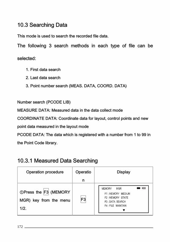
172
10.3 Searching Data
This mode is used to search the recorded file data.
The following 3 search methods in each type of file can be
selected:
1. First data search
2. Last data search
3. Point number search (MEAS. DATA, COORD. DATA)
Number search (PCODE LIB)
MEASURE DATA: Measured data in the data collect mode
COORDINATE DATA: Coordinate data for layout, control points and new
point data measured in the layout mode
PCODE DATA: The data which is registered with a number from 1 to 99 in
the Point Code library.
10.3.1 Measured Data Searching
Operation procedure Operatio
n
Display
①Press the F3 (MEMORY
MGR) key from the menu
1/2.
F3

173
② Press the F3 (DATA
SEARCH) keyF3
③Press the F1 (MEASURE
DATA) keyF1
④Enter the file name and
press the ENT key *1,*2
Enter FN
ENT
⑤Press the F3 key to enter
PT#, then press the ENT
key.
F3
Enter
PT#
ENT

174
Press the F4(P↓)key to
scroll the data for the
selected point. F4
*1)Refer to Section 1.10 “How to Enter Alphanumeric characters”.
*2)To show the file list, press the F2 (LIST) key.
Press the [▲]or[▼] key to scroll to next or previous point.
Edit measured data in search mode
In this mode PT#, ID, Pcode, Instrument Height and Prism Height can
be changed but
the measured data can not be modified.
Operation procedure Operatio
n
Display

175
①Press F1 (EDIT) key in data
display 1/3.F1
② Press[ ▲ ]or[▼]key to select
the data item to be modified.[▲][▼]
③Enter data.
Press ENT key
Enter
data
ENT
④ Press the F4 (SAVE) key
and the corrected data is
stored.
F4
*1)Refer to Section 1.10 “How to Enter Alphanumeric characters”.
10.3.2 Coordinate Data Searching
Example searching: Point number searching
Operation procedure Operation Display
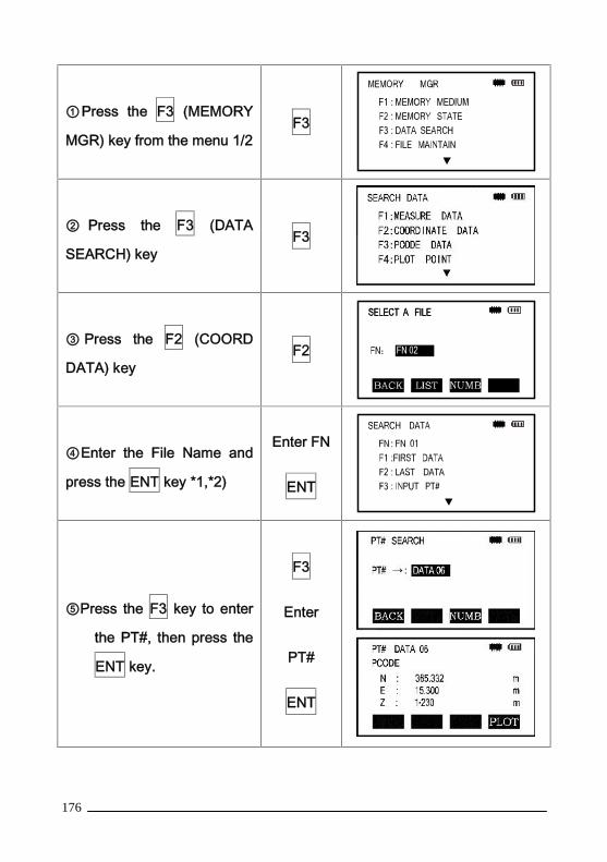
176
①Press the F3 (MEMORY
MGR) key from the menu 1/2F3
② Press the F3 (DATA
SEARCH) keyF3
③ Press the F2 (COORD
DATA) keyF2
④Enter the File Name and
press the ENT key *1,*2)
Enter FN
ENT
⑤Press the F3 key to enter
the PT#, then press the
ENT key.
F3
Enter
PT#
ENT

177
*1)Refer to Section 1.10 “How to Enter Alphanumeric characters”.
Press the [▲]or[▼] key to scroll to next or previous point.
10.3.3 PCODE LIBRARY Searching
Example searching: Register number searching
Operation procedure Operation Display
① Press the F3 (MEMORY
MGR) key from the menu 1/2.F3
② Press the F3 (DATA
SEARCH) keyF3
③ Press the F3 (PCODE
DATA) keyF3
④ Press the F3 (NO.
SEARCH) keyF3
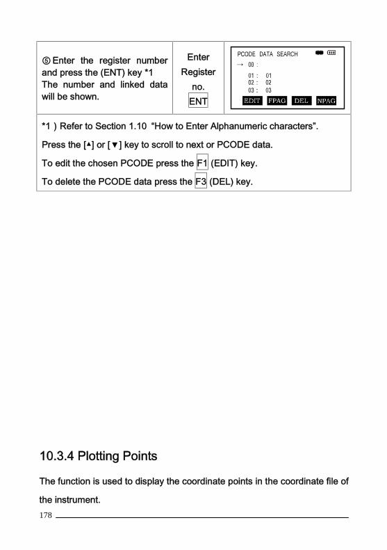
178
⑤ Enter the register numberand press the (ENT) key *1The number and linked datawill be shown.
EnterRegister
no.ENT
*1)Refer to Section 1.10 “How to Enter Alphanumeric characters”.
Press the [▲] or [▼] key to scroll to next or PCODE data.
To edit the chosen PCODE press the F1 (EDIT) key.
To delete the PCODE data press the F3 (DEL) key.
10.3.4 Plotting Points
The function is used to display the coordinate points in the coordinate file of
the instrument.

179
Operation procedure Operation Display
①Press F3 (MEMORY MGR)
key from the menu (1/3)F3
②Press F4 key to select a
plotting coordinate fileF4
③Select the starting points ofplotting. Just like the operationof data research after definethe plotting starting points,press F4 key
F4
④Now the coordinate pointsare displayed on the screen.The black block is the startingpoints.Press F1 or F2 to find the lastpoint or the next point, pressF3 or F4 key to reduce ormagnify the picture, press
、S.O、K1、K2 key to movethe picture.
10.4 File Maintenance

180
In this mode the following options are available:
Renaming file names
Searching data in a file
Deleting files
Pressing F4 (FILE MAINTAIN) key from MEMORY MANAGER menu 1/3
and the file listing will be shown.
FILE MAINTAN menu
File discrimination marks(*, &)are placed before the file name indicating the
file status.
“*”: current measure file
“&”: current coordinate file
Data discrimination character(M/ C)
“. RAW” Measured data file
“.PTS” Coordinate data file
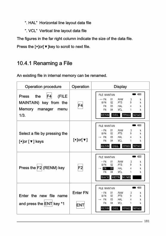
181
“. HAL” Horizontal line layout data file
“. VCL” Vertical line layout data file
The figures in the far right column indicate the size of the data file.
Press the [▲]or[▼]key to scroll to next file.
10.4.1 Renaming a File
An existing file in internal memory can be renamed.
Operation procedure Operation Display
Press the F4 (FILEMAINTAIN) key from theMemory manager menu1/3.
F4
Select a file by pressing the
[▲]or [▼] keys [▲]or[▼]
Press the F2 (RENM) key F2
Enter the new file name
and press the ENT key *1
Enter FN
ENT

182
*1)Refer to Section 1.10 “How to Enter Alphanumeric characters”.A file cannot be renamed to that of an existing file, an error message willbe displayed.To return to the FILE MAINTAN Menu, press the ESC key.
10.4.2 Deleting a File
This mode erases a file from internal memory - only one file can be erased
at a time.
Operation procedure Operation Display
① Press the F4 (FILE
MAINTAIN) key from the
Memory Manager menu
1/3.
F4
②Select a file to delete by
pressing the [▲]or [▼] key.[▲]or[▼]
③Press the F2 (DEL) key
F2
④Confirm the deleting by
pressing the F4 (YES) key. F4

183
To return to the FILE MAINTAIN Menu, press the ESC key.
10.5 Coordinate Data Direct Key Input
Coordinate data for the layout point or control point can be input
directly from the keyboard. The data can be stored into a file in the internal
memory.
Operation procedure Operation Display
①Press the F3 (MEMORY
MGR) key from the menu
1/2.
F3
②Press the ▼key for menu
MEMORY MGR 2/3▼
③ Press the F1 (INPUT
COORDINATE) keyF1
④Enter the File Name you
want to input. Press the ENT
key *1
Enter PN
ENT
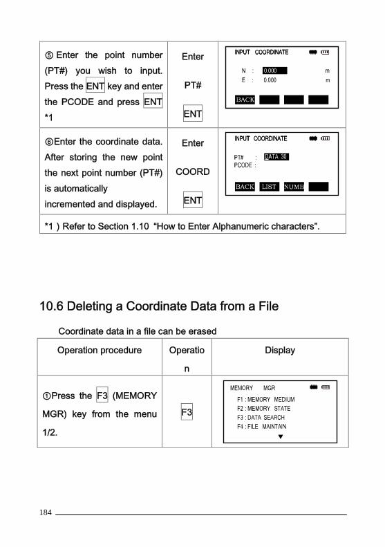
184
⑤ Enter the point number(PT#) you wish to input.Press the ENT key and enterthe PCODE and press ENT*1
Enter
PT#
ENT
⑥Enter the coordinate data.After storing the new pointthe next point number (PT#)is automaticallyincremented and displayed.
Enter
COORD
ENT
*1)Refer to Section 1.10 “How to Enter Alphanumeric characters”.
10.6 Deleting a Coordinate Data from a File
Coordinate data in a file can be erased
Operation procedure Operatio
n
Display
①Press the F3 (MEMORY
MGR) key from the menu
1/2.
F3
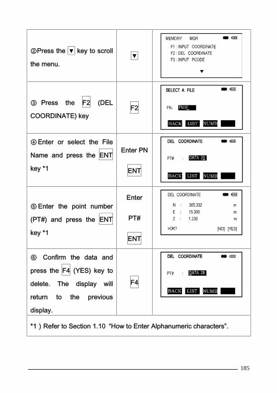
185
②Press the ▼ key to scroll
the menu.▼
③ Press the F2 (DEL
COORDINATE) keyF2
④Enter or select the File
Name and press the ENT
key *1
Enter PN
ENT
⑤ Enter the point number
(PT#) and press the ENT
key *1
Enter
PT#
ENT
⑥ Confirm the data and
press the F4 (YES) key to
delete. The display will
return to the previous
display.
F4
*1)Refer to Section 1.10 “How to Enter Alphanumeric characters”.
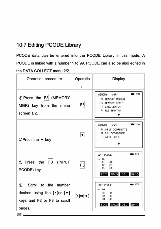
186
10.7 Editing PCODE Library
PCODE data can be entered into the PCODE Library in this mode. A
PCODE is linked with a number 1 to 99. PCODE can also be also edited in
the DATA COLLECT menu 2/2.
Operation procedure Operatio
n
Display
① Press the F3 (MEMORY
MGR) key from the menu
screen 1/2.
F3
②Press the ▼ key▼
③ Press the F3 (INPUT
PCODE) key.F3
④ Scroll to the number
desired using the [▲]or [▼]
keys and F2 or F3 to scroll
pages.
[▲]or[▼]
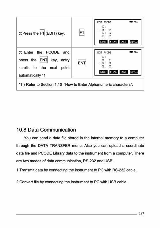
187
⑤Press the F1 (EDIT) key. F1
⑥ Enter the PCODE and
press the ENT key, entry
scrolls to the next point
automatically *1
ENT
*1)Refer to Section 1.10 “How to Enter Alphanumeric characters”.
10.8 Data CommunicationYou can send a data file stored in the internal memory to a computer
through the DATA TRANSFER menu. Also you can upload a coordinate
data file and PCODE Library data to the instrument from a computer. There
are two modes of data communication, RS-232 and USB.
1.Transmit data by connecting the instrument to PC with RS-232 cable.
2.Convert file by connecting the instrument to PC with USB cable.

188
10.8.1 Data Communication with RS-232
RS-232 Data Communication Menu:
F1: SEND DATA - send data from the instrument to the computer
F2: LOAD DATA - load data from the computer to the instrument
F3: COMM. PARAMETERS - set the communication parameters
Note: When transferring data check that the cables are connected
securely and that the parameter settings on the computer and Total Station
are consistent.
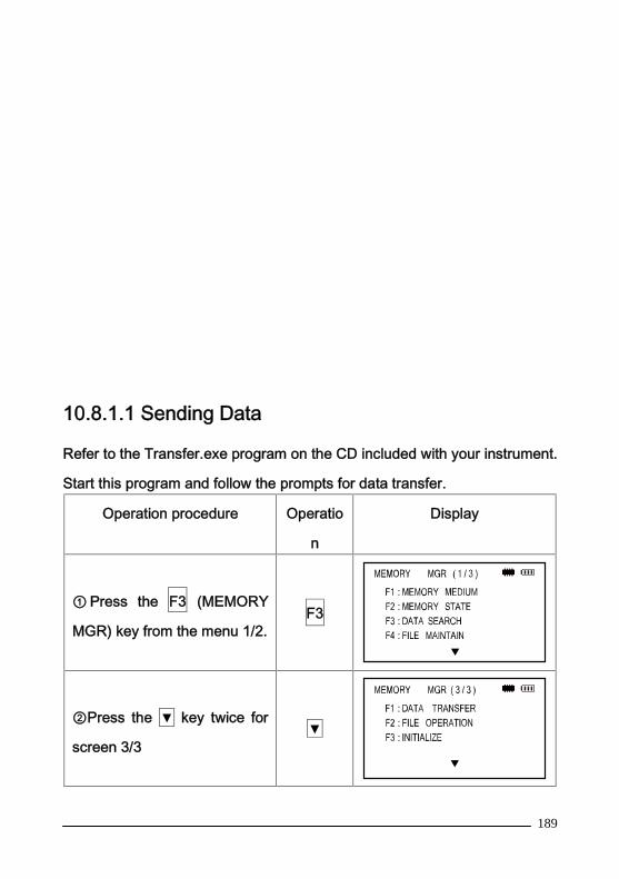
189
10.8.1.1 Sending Data
Refer to the Transfer.exe program on the CD included with your instrument.
Start this program and follow the prompts for data transfer.
Operation procedure Operatio
n
Display
① Press the F3 (MEMORY
MGR) key from the menu 1/2.F3
②Press the ▼ key twice for
screen 3/3▼

190
③ Press the F1 ( DATA
TRANSFER)keyF1
④ Press the F1 ( SEND
DATA)keyF1
⑤Select the type of data to
send by pressing the F1 –
F2 key.
Example: F1 (MEASURE
DATA)
F1
⑥Enter the File Name youwant to send and press theENT key *1,*2
Enter FN
ENT
⑦Press the F4 (YES)key *3The data transfer begins. Thedisplay will return to theSEND DATA menu after thetransfer is finished.
F4
*1)Refer to Section 1.10 “How to Enter Alphanumeric characters”.
*2)To scroll the data press the [▲]or [▼] key. To show the file list press
the F2 (LIST) key.
*3)To cancel transfer press the F4 (STOP) key.

191
10.8.1.2 Loading Data
Coordinate data files and PCODE Library data can be loaded from a PC.
Refer to the Transfer.exe program on the CD included with your instrument.
Start this program and follow the prompts for data transfer.
Example: Loading a coordinate data file.
Operation procedure Operatio
n
Display
①Press the F3 (MEMORY
MGR) key from the menu
1/2.
F3
②Press the ▼ key twice for
screen 3/3▼
③ Press the F1 (DATA
TRANSFER) key
F1
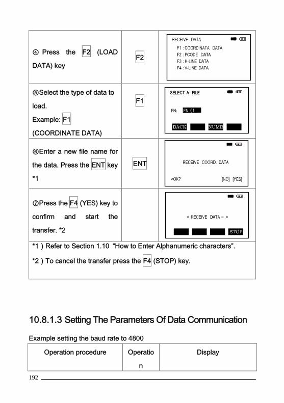
192
④ Press the F2 (LOAD
DATA) keyF2
⑤Select the type of data to
load.
Example: F1
(COORDINATE DATA)
F1
⑥Enter a new file name for
the data. Press the ENT key
*1
ENT
⑦Press the F4 (YES) key to
confirm and start the
transfer. *2
*1)Refer to Section 1.10 “How to Enter Alphanumeric characters”.
*2)To cancel the transfer press the F4 (STOP) key.
10.8.1.3 Setting The Parameters Of Data Communication
Example setting the baud rate to 4800
Operation procedure Operatio
n
Display

193
①Press the F3 (MEMORY
MGR) key from the menu
1/2.
F3
②Press the ▼ key twice ▼
③ Press the F1 ( DATA
TRANSFER)keyF1
④Press the F3 (COMM
PARAMETERS)key F3

194
⑤Press the F1, F2 and F3
keys one by one to select
BAUD RATE, CHAR
CHECKOUT and
PROTOCOL.
The parameters need to be
consistent between the
instrument and the
Transfer.exe program.
F1
F2
F3
⑥ After selecting each
parameter press the ENT
key *1
ENT
*1)BAUD RATE can be set to: 1200, 2400, 4800, 9600, 19200, 38400,
57600, or 115200 b/s. Select by pressing the F3 (DECE) or F4 (ADD) key.
*2)To cancel the setting press the ESC key.
These settings will be saved as the default values after powering off.

195
10.8.2 Data Conversion by USB
Start up the instrument, connect the instrument to PC with USB cable,
the menu is displayed on the screen as below.
USB Working……
Please
disconnection
Press <ESC> to
exit!
This reprensents the connection is normal, then you can operate the
data file stored in the instrument by data transmission software, It is also
possible to copy the file on PC into the instrument.
10.8.2.1 Data Export
Data type in the memory of total station
1. *. RAW—Measurement file
2. *. PTS—Coordinate file
3. *. HAL—Horizontal line location file
4. *. VCL—Verical line location file
5. *. PCOPE. LIB—Pcode file
In order to export the relevant data fromcertain file, you can just open
the corresponding file by data transmissing software.
For example: Open TS. RAW file
196
Start transmission software, select“open EMS file” in the meau“ USB
operation”, then select “open*. RAW(measurement data file)” and choose
“TS. RAW” file of the memory to realize opening the TS. RAW file, the
measurement data will be displayed in the transmission software and can
be stored in PC.
10.8.2.2 Data Inport
For example: Inporting POCDE data
Start the data transmission software, import the coding which is
needing to be imported in the text box or open the PCODE file of text style
which has been edited already.
The encoding format is as below
1. CODE
2. HOUSE
3. TREE
Up to 500 codes can be input, after inputing the codes, select“convert
EMS memory file”in the menu“USB operation”,choose “*.txt PCODE.
LIB” to realize the conversion, store the data in the memory of the
instrument.
Note: Only one encoding file is allowed to exist, and the file name can’t be
modified, the file can only be covered, In addition, the file can only be stored
in the memory, not in the SD card.

197
10.9 File Operation
This function is used to realize the mutual copy between the memory
and SD card.
10.9.1 Copy File From SD Card To Memory Of The
Instrument
Operation procedure Operation Display
① Press F2 key from
MEMORY MGR.(3/3) menu
to get FILE OPERATION
F2
② Press F1 key to enter
import interface, the file
names existing in SD card
are displayed.
F1

198
③Select a file name , press
ENT key.ENT
④Input a file name for the
inported, then press ENT
key to finish the operation.
ENT
10.9.2 Copy The File From Memory To SD Card.
This operation procedure is similar to the section 10.9.1 just introduced
above, the only difference is to press F2 key instead of F1 key in the
second step of the section 10.9.1
Operation procedure Operation Display
①Press the F2 key from
MEMORY MGR.(3/3)
menu to get FILE
OPERATION
F2

199
② Press the F2 key:
WORK EMS→SD CARD. F2
③Press the F1 or F2 key
to choose an export file
type.
F1 F2
④Choose a file to export
and press the ENT key.ENT
⑤Press the F1 or F2 key
to choose an export file
data type.
F1 F2
⑥Enter a new file name
and press the ENT key to
convert and store.
ENT
200
10.10 InitializationThis mode is used to initialize the internal memory. Following data can be
initialized:
FILE DATA: All measuring data and coordinate data. (data in the files)
PCODE DATA: PCODE list.
ALL FILE: All files will be deleted. (except PCODE).
For example: Initialize all files.
Operation procedure Operatio
n
Display

201
① Press the F3 (MEMORY
MGR) key from the menu 1/2.F3
②Press the ▼ key twice ▼
③Press the F3 (INITIALIZE)
keyF3
④Select the data to initialize
by pressing the F1 to F3
keys.
Example:F2 (ALL FILE)
F3
⑤ To confirm the erase
function press the F4 (YES)
key. Initializing will begin.
F4
Note: The following data will not be initialized during this process:
Instrument Coordinates
Instrument Height
Target Height.

202
11. BASIC SETTINGSThe instruments basic function settings should be monitored and set for
each job.
Operation procedure is as follows:
Operation procedure Operation Display

203
Press the M key to get the
main MENU 1/2.M
Press the F4 (CONFIG) from
the main MENU(1/2) to get
CONFIG menu.
F4
11.1 Unit Settings
Setting the instrument units as needed.
Operation procedure Operation Display
In CONFIG (1/2), press the
F1 key to get to the UNIT
SET menu.
F1
Press the F1 to F4 keys toset the angle, temperature,air pressure and distancevariables.
Select unit and parameter
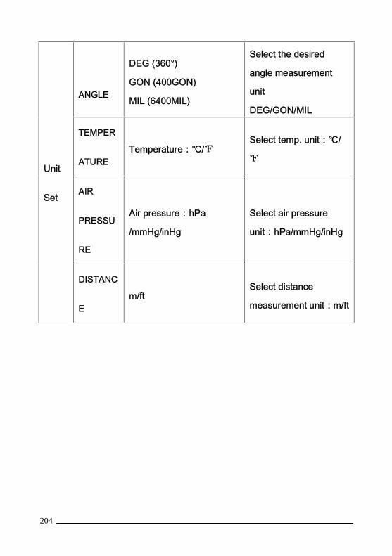
204
Unit
Set
ANGLE
DEG (360°)
GON (400GON)
MIL (6400MIL)
Select the desired
angle measurement
unit
DEG/GON/MIL
TEMPER
ATURETemperature:℃/℉
Select temp. unit:℃/
℉
AIR
PRESSU
RE
Air pressure:hPa
/mmHg/inHg
Select air pressure
unit:hPa/mmHg/inHg
DISTANC
Em/ft
Select distance
measurement unit:m/ft
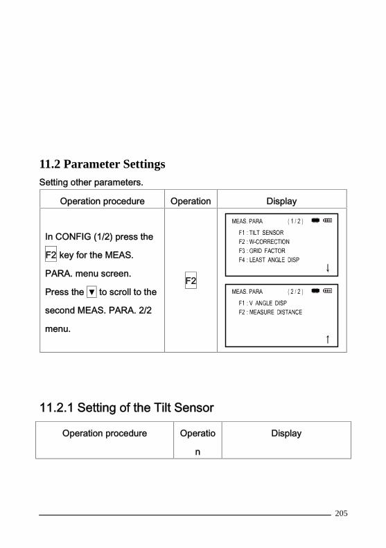
205
11.2 Parameter SettingsSetting other parameters.
Operation procedure Operation Display
In CONFIG (1/2) press the
F2 key for the MEAS.
PARA. menu screen.
Press the ▼ to scroll to the
second MEAS. PARA. 2/2
menu.
F2
11.2.1 Setting of the Tilt Sensor
Operation procedure Operatio
n
Display

206
Press the F1 key from the
MEAS. PARA. menu to get to
the TILT SENSOR display.
F1
Press F3 key turn on,press F4
key turn off.
F3
F4
If the instrument is with dual axis compensator.
The operation is as below.
①Press the F1 key from the
MEAS. PARA. Seting menu to
get to the TILT SENSOR
display.
F1
②Press F3 or F4 key to turn
on or off X axis or Y axis
compensator.
F3
F4
11.2.2 Setting of the W-Correction
The instrument will automatically correct the influence of atmosphere
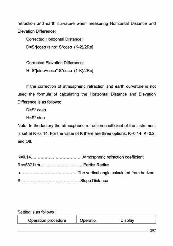
207
refraction and earth curvature when measuring Horizontal Distance and
Elevation Difference:
Corrected Horizontal Distance:
D=S*[cosα+sinα* S*cosα (K-2)/2Re]
Corrected Elevation Difference:
H=S*[sinα+cosα* S*cosα (1-K)/2Re]
If the correction of atmospheric refraction and earth curvature is not
used the formula of calculating the Horizontal Distance and Elevation
Difference is as follows:
D=S* cosα
H=S* sinα
Note: In the factory the atmospheric refraction coefficient of the instrument
is set at K=0. 14. For the value of K there are three options, K=0.14, K=0.2,
and Off.
K=0.14……………………………… Atmospheric refraction coefficient
Re=6371km………………………… Earths Radius
α……………………………………The vertical angle calculated from horizon
S ……………………………………Slope Distance
Setting is as follows:
Operation procedure Operatio Display

208
n
Press the F2 key from the
MEAS. PARA. Menu to get to
the W-CORRECTION screen.
F2
Press F1 to F3 key to select
the atmospheric refraction
coefficient of the
W-CORRECTION.
F1-F3
11.2.3 Setting the GRID FACTOR
Calculation Formula
1)Elevation factor
Elevation factor =R/(R+ELEV)
R:the average radius of the earth
ELEV:the elevation above mean sea level
2)Scale factor
Scale factor at the surveying station
3)Grid factor
Grid factor = Elevation factor×Scale factor
Distance calculation
1)Grid distance

209
HDg=HD×Grid factor
HDg:Grid distance
HD:Ground distance
2)Ground distance
HD= HDg/Grid factor
Setting is as follows:
Operation procedure Operation Display
Press F3 key from MEAS.
PARA. menu to get to the
GRID FACTOR screen.
F3
Press the F1 (ON) key to
turn on the GRID FACTOR.F1
Press the F4 (MODY) key to
modify.F4
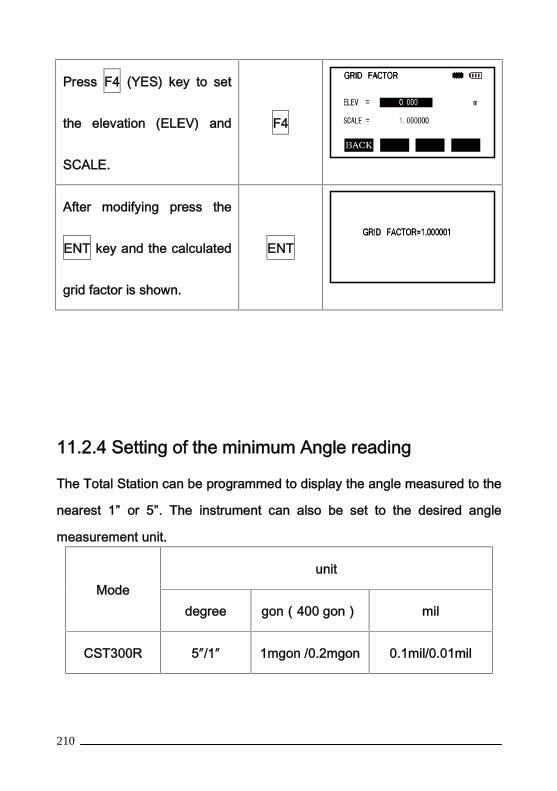
210
Press F4 (YES) key to set
the elevation (ELEV) and
SCALE.
F4
After modifying press the
ENT key and the calculated
grid factor is shown.
ENT
11.2.4 Setting of the minimum Angle reading
The Total Station can be programmed to display the angle measured to the
nearest 1” or 5”. The instrument can also be set to the desired angle
measurement unit.
Modeunit
degree gon(400 gon) mil
CST300R 5″/1″ 1mgon /0.2mgon 0.1mil/0.01mil

211
Minimum angle display reading.
Operation procedure Operatio
n
Display
Press the F4 key from the
MEAS. PARA. menu to get to
the LEAST ANGLE DISP
screen.
F4
Press F2 to choose 5” or F1
to choose the 1 ” display
mode, then press the ENT
key to confirm. This setting
does not effect the accuracy
of the instrument.
F2
11.2.5 Setting the vertical angle display
The vertical angle display can be measured from Zenith or the horizontal
plane. The Z0 (zenith) method is the most often used for surveying
purposes, the “0” value will be directly overhead.
Operation procedure Operation Display

212
Press F1 key from MEAS
PARA. menu 2/2 for the V
ANGLE Z0/H0 screen
F1
Press the F2 (H0) key then
press the ENT key to
return to MEAS PARA
menu.
F2
11.2.6 Setting Of Plotting Points Number
Setting of the maxmum points number displayed on the screen.
Operation procedure Operation Display
Press F2 in the menu
measured parameter (2/2)
setting interface to enter
setting of plotting points
number interface.
F2
Input the points number
needing to be displayed and

213
then press ENT key.
11.2.7 Setting the Distance Range Mode
The Total Station has the option of defining the normal distance measured
during operation to increase measuring efficency:
0-2KM (0-1.2 miles): Selecting this option gives the quickest measurement
times.
0-5KM (0-3 miles): Use this mode when measuring longer distances.
Operation procedure Operation Display
Press the F2 key from
MEAS PARA. menu 2/2 to
get to the MEASURE
DISTANCE screen.
F2
Press the F2 (0-5KM) or F1
(0-2KM) key and then the
ENT key to select and return
to the MEAS PARA. menu.
F2 or F1
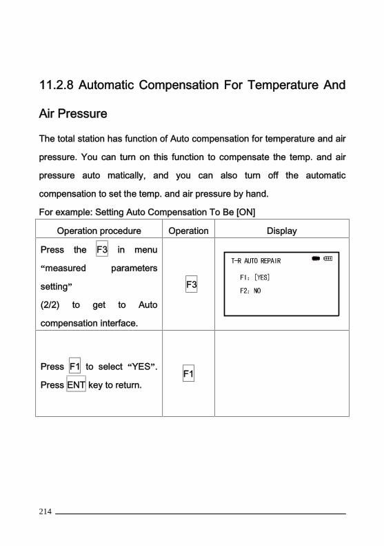
214
11.2.8 Automatic Compensation For Temperature And
Air Pressure
The total station has function of Auto compensation for temperature and air
pressure. You can turn on this function to compensate the temp. and air
pressure auto matically, and you can also turn off the automatic
compensation to set the temp. and air pressure by hand.
For example: Setting Auto Compensation To Be [ON]
Operation procedure Operation Display
Press the F3 in menu
“measured parameters
setting”
(2/2) to get to Auto
compensation interface.
F3
Press F1 to select “YES”.
Press ENT key to return.F1

215
11.3 Setting the measure mode display
The default display in the measure modes can be set by pressing [F3]
POWER ON DISPLAY on menu 1/2 in the CONFIG screen:
Shown
F1: MEASURE
MODE
Angle or
distance
Choose the angle or distance
measuring mode.
F2: HD&VD /SDHD&VD
/SD
Choose the distance mode -
Horizontal &Vertical Distance
or Slope Distance
F3: COORD.
FORMATENZ/NEZ
Select the coordinate display
order ENZ or NEZ
11.4 Setting the Shortcut KeysThe CST300R has two shortcut keys that can be configured by the user.
Shortcut key Operation Function
K1Press the K1 key for 1second 1、 REM
2、 MLM3、 AREAPress F4 key from CONFIG menu

216
K2
Press the K2 key for 1second. 4、 Z COORD.5、 POINT TO LINE6、 ROAD7、 RESECTION8、 NONE
Press the F4 key from theCONFIG menu
11.5 Other Settings
The instrument can be set to auto matically power off, change the battery
type, reset configuations and select the operating language.
Operation procedure Operatio
n
Display
Press F1 (OTHERS SET)
from the CONFIG menu 2/2.F2
11.5.1 Auto Power Off
If there is no key operation or ongoing measurement in 60 minutes the
instrument will power off automatically.
Operation procedure Operatio
n
Display
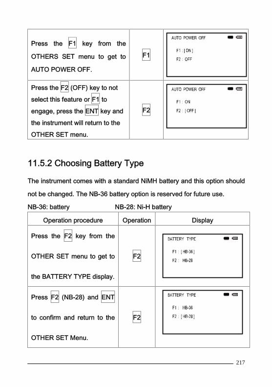
217
Press the F1 key from the
OTHERS SET menu to get to
AUTO POWER OFF.
F1
Press the F2 (OFF) key to not
select this feature or F1 to
engage, press the ENT key and
the instrument will return to the
OTHER SET menu.
F2
11.5.2 Choosing Battery Type
The instrument comes with a standard NiMH battery and this option should
not be changed. The NB-36 battery option is reserved for future use.
NB-36: battery NB-28: Ni-H battery
Operation procedure Operation Display
Press the F2 key from the
OTHER SET menu to get to
the BATTERY TYPE display.
F2
Press F2 (NB-28) and ENT
to confirm and return to the
OTHER SET Menu.
F2
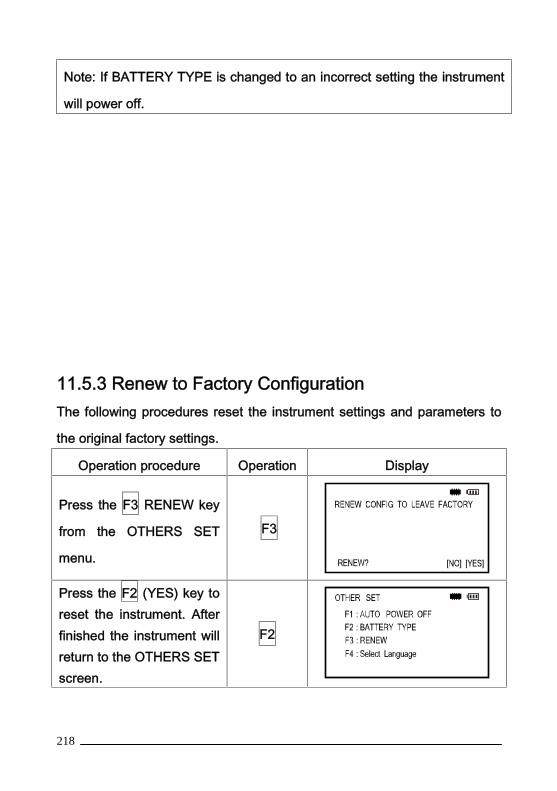
218
Note: If BATTERY TYPE is changed to an incorrect setting the instrument
will power off.
11.5.3 Renew to Factory ConfigurationThe following procedures reset the instrument settings and parameters to
the original factory settings.
Operation procedure Operation Display
Press the F3 RENEW key
from the OTHERS SET
menu.
F3
Press the F2 (YES) key toreset the instrument. Afterfinished the instrument willreturn to the OTHERS SETscreen.
F2

219
11.5.4 Selecting a Language
The instrument can be set to an alternative language using the flowing
procedures.
Operation procedure Operation Display
Press the F4
SelectLanguage key from
the OTHERS SET menu.
F3
Press the F1 or F2 key to
select the desired language,
press ENT and the
instrument will return to the
OTHERS SET screen.
F2
11.6 Date and Time
The date and time can be set using the following procedures:
Operation procedure Operatio
n
Display
Press the F1(EMENDATION) key fromthe main menu page 2/2
F1

220
Press the F3 (TIME ANDDATE) key to set time anddate.
F3
Press the F1 or F2 key toset date and time. Afterentry press the ESC key toreturn to ADJUSTMENTMODE.
F1 F2
11.7 Adjusting the Contrast of the LCD
The contrast of the LCD can be adjusted using the following procedures:
Operation procedure Operatio
n
Display
Press the F1(EMENDATION) key from themain menu page 2/2.
F1

221
Press the F4 (LCDCONTRAST) key to get tothe CONTRAST screen.
F4
Press F2 and F3 keys to setthe contrast, after finishedpress the ESC key to returnto ADJUSTMENT MODE.
F2 F3
12. CHECK AND ADJUSTMENTThe instrument has been checked and adjusted thoroughly at the
factory to insure the instrument meets our quality requirements. But long
distance transportation and the change of the environment could cause the
instrument to go out of adjustment. It is recommended before using the
instrument it should be checked and adjusted according to the procedures
outlined below.

222
12.1 Plate Vial
Inspection
Refer to Section 1.4 Instrument Set Up and “Leveling by using the
plate vial”
Adjustment
1. Place instrument on the tripod.
2. Face the instrument with two of the three leveling screws in front of
you.
3. Rotate the right level screw to center the plate vial bubble.
4. Move instrument CCW and rotate the next right level screw to center
the plate vial bubble again.
5. Move instrument CCW and rotate the next right level screw to center
the plate vial bubble again.
6. Now, move CCW to the next position and check to see if the bubble is
centered.
7. If the plate vial bubble is not centered, remove 1/2 of the error with
right level screw and 1/2 of the error with the plate vial adjusting screw.
8. Repeat steps 4, 5, and 6.

223
9. If there is still an offset error with the plate vial bubble repeat
procedure until bubble is centered.
12.2 Circular VialInspection
No adjustment is necessary if the bubble of the circular vial is in the
center aftcr inspection and adjustment of the plate vial.
Adjustment
If the bubble of the circular vial is not in the center bring the bubble to
the center by using the adjusting pin or hexagon wrench to adjust the
bubble adjusting screw. First loosen the screw opposite to the offset side
and then tighten the other adjusting screw on the offset side, bringing the
bubble to the center. After the bubble stays in the center each of the three
adjustment screws should be tightened in a uniform manner.
12.3 Inclination of ReticleInspection
1. Sight object A through the telescope and lock the horizontal and
vertical clamp screws.
2. Move object A to the edge of the field of view with the vertical tangent

224
screw (point A' )
3. No adjustment is necessary if object A moves along the vertical line
of the reticle and point A' is still in the vertical line.
As illustrated A ' offsets from the center and the cross hair tilts, then the
reticle needs adjustment.
Adjustment
1. If the object A does not move along the vertical line, first remove the
eyepiece cover to expose the four reticle adjusting screws.
2. Loosen the four reticle adjusting screws uniformly with an adjusting
pin. Rotate the reticle around the sight line and align the vertical line of the
reticle with point A '
3. Tighten the reticle adjusting screws uniformly, pepeat the inspection
and adjustment to see if the adjustment is correct.
4. Replace the eyepiece cover.

225
12.4 Perpendicularity of line of sight to Horizontal Axis(2c)
Inspection
1. Set an object A at a far distance the same height as the instrument,
then level and center the instrument and turn on the power.
2. Sight object A in the left position and read the horizontal angle value
( horizontal angle L=10°13 '10″ ).
3. Loosen the vertical and horizontal clamp screws and rotate the
telescope. Sight object
A in right position and read the horizontal angle value.(horizontal angle R
= 190°13′40″).
4.2C=L-(R±180°)=-30″≥±20″,adjustment is necessary.

226
Adjustment
1. Use the tangent screw to adjust the horizontal angle reading,
2. Take off the cover of the reticle between the eyepiece and focusing
screw. Adjust the two adjusting screws by loosening one and tightening the
other. Move the reticle to sight object A exactly.
3. Repeat inspection and adjustment until|2C|<20″.
4. Replace the cover of the reticle.
12.5 Vertical Index Difference CompensationInspection
1. Mount and level the instrument and make the telescope parallel with
the line connecting the center of the instrument to any one of the screws.
Lock the horizontal clamp screw.
2. After turning on the power, zero the vertical index. Lock the vertical
clamp screw and the instrument should display the vertical angle value.
3. Rotate the vertical clamp screw slowly in either direction about
10mm in circumference, and the error message "b" will appear. The vertical
axis has increased to more than 3" at this time and exceeds the designated
compensation range.
Rotate the above screw to its original position, and the instrument
display screen will show the vertical angle again, meaning that the vertical
index difference compensation function is working.
Adjustment
If the compensation function is not working, send the instrument back

227
to the factory for repair.
12.6 Adjustment of Vertical Index Difference ( i angle)and Vertical Angle 0 Datum
Inspect the item after finishing the inspection and adjustment of item
13.3 and 13.4.
Inspection
1. Power on after leveling the instrument. Sight object A in left position
and read the
Verticail angle value L.
2. Rotate the telescope. Sight object B in right position and read the
Verticail angle value R.
3.If the vertical angle is0°in zenith,,i=(L+R-360°)/2
If the vertical angle is0°in horizoni=(L+R-180°)/2 or (L+R
-540°)/2。
4. If |i| ≥10″ set the Vertical Angle 0 Datum again.
Adjustment
1. After leveling the instrument, go to the main menu screen 2/2 and
press the F1 key:

228
2. In left position rotate the telescope. Precisely sight any target A at the
same height as the instrument, the vertical angle is displayed. Press the F4
key:
3. Rotate the telescope and precisely sight the same target. Press the
F4 key. The setting is finished and the instrument returns to the previous
Angle Measurement Mode:
F1: V ANGLE 0 POINTADJUSTMENT MODE
F2: INST. CONSTANTF3: TIME AND DATA
F4: LCD CONTRAST
V ANGLE 0 ADJUST
ENT
<STEP-1> FRONTV : 95° 30’ 5 5’ ’
V ANGLE 0 POINT
<STOP-2> REVERSE
V : 2 64 ° 2 9 ’ 0 0 ’ ’
ENT
229
4. Repeat the inspection steps to measure the Index difference ( I
angle). If the Index
Difference does not meet requirements redo the steps above. Carefull
sighting must be done to insure the proper result..
5. If Index Difference does not meet the requirements after the
repeated operation the instrument should be returned to factory for
inspection and repair.
Method: in step three, press the F1 (SET) key after collimating the
target A.
The vertical angles shown in the Vertical Angle 0 Datum are only for
reference.
12.7 Optical PlummetInspection
1. Set the instrument on the tripod and place a piece of white paper with
two perpendicular lines under the instrument.
2. Adjust the focus of the optical plummet and move the paper so that
the intersection point of the lines on the paper comes to the center of the
field of view.
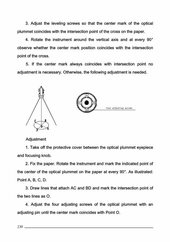
230
3. Adjust the leveling screws so that the center mark of the optical
plummet coincides with the intersection point of the cross on the paper.
4. Rotate the instrument around the vertical axis and at every 90°
observe whether the center mark position coincides with the intersection
point of the cross.
5. If the center mark always coincides with intersection point no
adjustment is necessary. Otherwise, the following adjustment is needed.
Adjustment
1. Take off the protective cover between the optical plummet eyepiece
and focusing knob.
2. Fix the paper. Rotate the instrument and mark the indicated point of
the center of the optical plummet on the paper at every 90°. As illustrated:
Point A, B, C, D.
3. Draw lines that attach AC and BD and mark the intersection point of
the two lines as O.
4. Adjust the four adjusting screws of the optical plummet with an
adjusting pin until the center mark coincides with Point O.

231
5. Repeat the inspection and adjusting steps to be sure the adjustment
is correct.
6. Replace the protective cover.
12.8 Laser PlummetA laser plummet tribrach may be ourchased separately for the
instruments.
12.9 Instrument Constant (K)The instrument constant has been checked and adjusted in the factor,
K=0. It changes seldom and it is suggested to check one or two times every
year. The inspection should be made on a base line but also can be made
according to the following method.
Inspection
1. Mount and level the instrument on Point A in a flat area. Use the
vertical hair to mark Point B and Point C on the same line with the distance
of 50m between each point. Set the reflector accurately on each point when
measuring.
2. After setting temperature and air pressure in the instrument measure
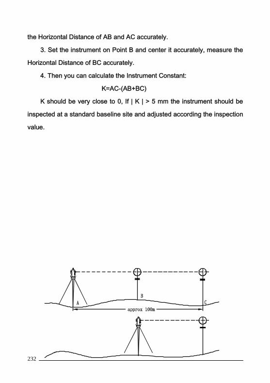
232
the Horizontal Distance of AB and AC accurately.
3. Set the instrument on Point B and center it accurately, measure the
Horizontal Distance of BC accurately.
4. Then you can calculate the Instrument Constant:
K=AC-(AB+BC)
K should be very close to 0, If | K | > 5 mm the instrument should be
inspected at a standard baseline site and adjusted according the inspection
value.
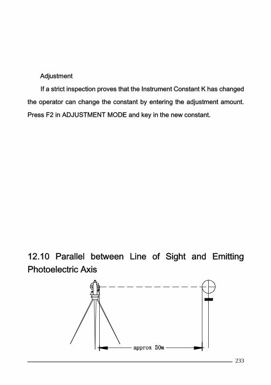
233
Adjustment
If a strict inspection proves that the Instrument Constant K has changed
the operator can change the constant by entering the adjustment amount.
Press F2 in ADJUSTMENT MODE and key in the new constant.
12.10 Parallel between Line of Sight and EmittingPhotoelectric Axis

234
Inspection1. Set the reflector 50m from the instrument.2. Sight the center of the reflector prism with reticle.3. Power on and enter Distance Measurement Mode. Press MEAS to
measure.Rotate the Horzontal Tangent Screw and Vertical Tangent Screw, to do
electric collimation and make the light route of EDM unblocked. In the bightzone find the center of emiting photoelectric axis.
4. Check whether the center of reticle coincides with the center ofemiting photoelectric axis. If so, the instrument is up to grade.
AdjustmentIf there is great difference between the center of reticle and the center
of emiting photoelectric axis the instrument needs repair.
12.11 Tribrach Leveling ScrewIf the leveling screw becomes loose adjust the two adjusting screws in
the leveling screw to tighten appropriately.

235
13 Specifications
HTS-580AGX HTS-580A
Model Reflectorless Standard
Laser Class Class 3R Laser product NA
Conformity IEC 60852-1:2001 EN 60825-1:1994+A11:1996
Telescope Fully Transiting, Coaxial Sighting & Distance Measuring
Optics
Lmage Erect
Magnification 3OX
Objective Aperture 45mm; EDM,50mm
Resolving Power 3″
Field of view 1℃30′
Minimum Focus 1m
Angle Measurement Absolute encode
Display Resolution 1″/5″Selectable
Angle Accuracy(DIN
18723)
2″ 5″ 2″ 5″
Measuring Mode H:Clockwise/Couterclockwise Selectable,0 set,Angle
Input,Availability.&
V:Zenith 0/Horizontal 0,selectable
Measuring time 0.8S 1.8S
Distance
Measurement
Modulated laser type:0.670μm
Basic Frequency:60MHZ,Coaxial
Infra-Red
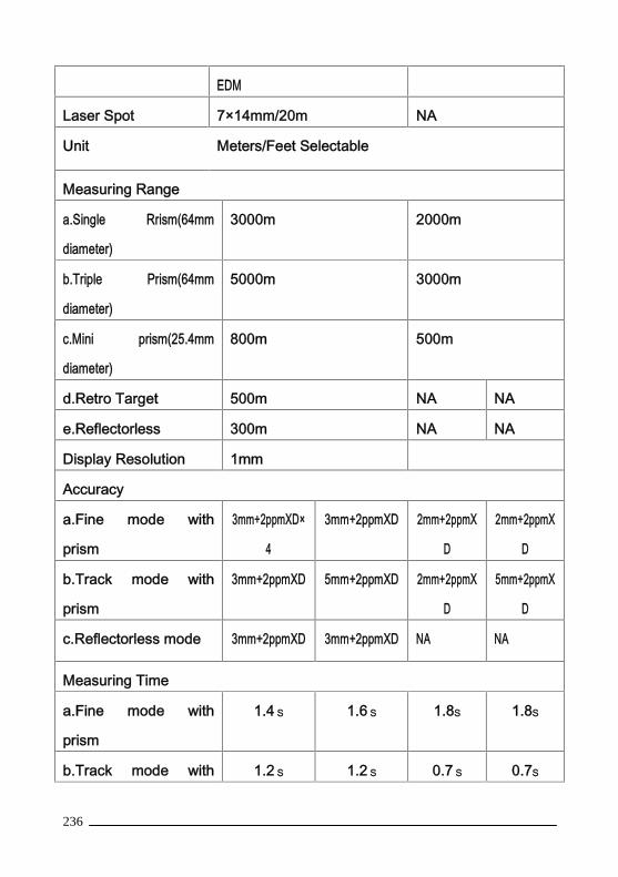
236
EDM
Laser Spot 7×14mm/20m NA
Unit Meters/Feet Selectable
Measuring Range
a.Single Rrism(64mm
diameter)
3000m 2000m
b.Triple Prism(64mm
diameter)
5000m 3000m
c.Mini prism(25.4mm
diameter)
800m 500m
d.Retro Target 500m NA NA
e.Reflectorless 300m NA NA
Display Resolution 1mm
Accuracy
a.Fine mode with
prism
3mm+2ppmXD×
4
3mm+2ppmXD 2mm+2ppmX
D
2mm+2ppmX
D
b.Track mode with
prism
3mm+2ppmXD 5mm+2ppmXD 2mm+2ppmX
D
5mm+2ppmX
D
c.Reflectorless mode 3mm+2ppmXD 3mm+2ppmXD NA NA
Measuring Time
a.Fine mode with
prism
1.4 S 1.6 S 1.8S 1.8S
b.Track mode with 1.2 S 1.2 S 0.7 S 0.7S
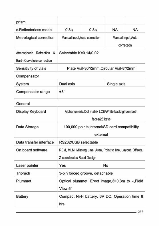
237
prism
c.Reflectorless mode 0.8 S 0.8 S NA NA
Metrological correction Manual input,Auto correction Manual Input,Auto
correction
Atmospheric Refraction &
Earth Curvature correction
Selectable K=0.14/0.02
Sensitivity of vials Plate Vial-30″/2mm,Circular Vial-8″/2mm
Compensator
System Dual axis Single axis
Compensator range ±3′
General
Display Keyboard Alphanumeric/Dot matrix LCE/White backlight/on both
faces/28 keys
Data Storage 100,000 points internal/SD card compatibility
external
Data transfer interface RS232/USB selectable
On board software REM, MLM, Missing Line, Area, Point to line, Layout, Offsets.
Z-coordinates Road Design
Laser pointer Yes No
Tribrach 3-pin forced groove, detachable
Plummet Optical plummet: Erect image,3×0.3m to ∞,Field
View 5°
Battery Compact Ni-H battery, 6V DC, Operation time 8
hrs

238
Charger Quick battery charger with separate power cord
Operating temperature -20℃ to +50℃
Size and Weight 200×180×350mm, 5.8kg
*1 under good conditions: No haze, Visibility
about 40km(25 miles), Overcast, No Scinyillation
*2 With HORIZON retro target/white side of a
KODAK Grey Card Reflective(A4 × 18% × gray
0.18°)
*3 At dawn & dusk or when the target is shadowed
*4 (D=Measuring distance, unit:mm)
Waterproof IP54 Standard
14. ERROR DISPLAYS
Error code Description CountermeasuresCALC ERROR Calculation is impossible
because of error in datainput.
Enter correct data.
FILE EXISTS The same file nameexists.
Use another file name.
FULL FILES The maximum of 48 filesare already created.
If necessary transmit ordelete files.
OVERTOP The measurement iscarried out over 45 °
Measure a new point.
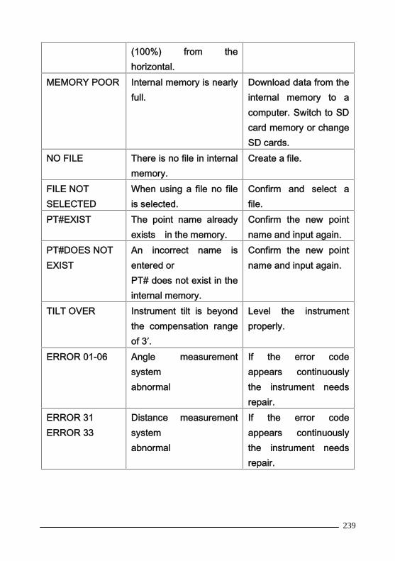
239
(100%) from thehorizontal.
MEMORY POOR Internal memory is nearlyfull.
Download data from theinternal memory to acomputer. Switch to SDcard memory or changeSD cards.
NO FILE There is no file in internalmemory.
Create a file.
FILE NOTSELECTED
When using a file no fileis selected.
Confirm and select afile.
PT#EXIST The point name alreadyexists in the memory.
Confirm the new pointname and input again.
PT#DOES NOTEXIST
An incorrect name isentered orPT# does not exist in theinternal memory.
Confirm the new pointname and input again.
TILT OVER Instrument tilt is beyondthe compensation rangeof 3′.
Level the instrumentproperly.
ERROR 01-06 Angle measurementsystemabnormal
If the error codeappears continuouslythe instrument needsrepair.
ERROR 31ERROR 33
Distance measurementsystemabnormal
If the error codeappears continuouslythe instrument needsrepair.

240
15. SAFETY INSTRUCTIONS15.1 Integrated EDM(Visible Laser)Warning:
Total station with EDM of laser class 3R resp.a-identifiable by:
Warning decal is above the vertical braking screw in Face 1: “Class III
Laser Product”.
The product is a class 3R laser product in accordance with:
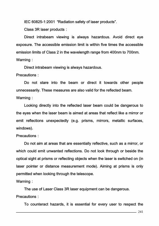
241
IEC 60825-1:2001 “Radiation safety of laser products”.
Class 3R laser products:
Direct intrabeam viewing is always hazardous. Avoid direct eye
exposure. The accessible emission limit is within five times the accessible
emission limits of Class 2 in the wavelength range from 400nm to 700nm.
Warning:
Direct intrabeam viewing is always hazardous.
Precautions:
Do not stare into the beam or direct it towards other people
unnecessarily. These measures are also valid for the reflected beam.
Warning:
Looking directly into the reflected laser beam could be dangerous to
the eyes when the laser beam is aimed at areas that reflect like a mirror or
emit reflections unexpectedly (e.g. prisms, mirrors, metallic surfaces,
windows).
Precautions:
Do not aim at areas that are essentially reflective, such as a mirror, or
which could emit unwanted reflections. Do not look through or beside the
optical sight at prisms or reflecting objects when the laser is switched on (in
laser pointer or distance measurement mode). Aiming at prisms is only
permitted when looking through the telescope.
Warning:
The use of Laser Class 3R laser equipment can be dangerous.
Precautions:
To counteract hazards, it is essential for every user to respect the

242
safety precautions and control measures specified in standard
IEC60825-1:2001 within the hazardous distance range.
Below is an interpretation of the main points in the relevant section of
the standard quoted.
Class 3R laser products used on construction sites and outdoors (surveying,
alignment, leveling):
a) Only qualified and trained persons should be assigned to install,
adjust and operate the laser equipment.
b) Areas in which these lasers are used should be posted with an
appropriate laser warning sign.
c) Precautions should be taken to ensure that persons do not look
directly, with or without an optical instrument, into the beam.
d) The laser beam should be terminated at the end of its useful beam
path and should in all cases be terminated if the hazardous beam path
extends beyond the limit (hazard distance *)) of the area in which the
presence and activities of personnel are monitored for reasons of protection
from laser radiation.
e) The laser beam path should be located well above or below eye
level wherever practicable.
f) When not in use the laser product should be stored in a cool and dry
location.
g) Precautions should be taken to ensure that the laser beam is not
unintentionally directed at mirror-like (mirrored) surfaces (e.g. mirrors, metal
surfaces, windows) and more importantly, at flat or concave mirror-like

243
surfaces.
*) The hazard distance is the distance from the laser at which beam
irradiance or radiant exposure equals the maximum permissible value to
which personnel may be exposed without being exposed to a health risk.
Products with an integrated EDM of laser class 3R resp. IIIa has a
hazard distance of 1000m (3300ft). After this distance, the laser beam rates
as Class 1 (= direct intrabeam viewing is not hazardous).
15.2 Laser PlummetA laser plummet tribrach is available for this instrument. Please contact
your local representative for information.
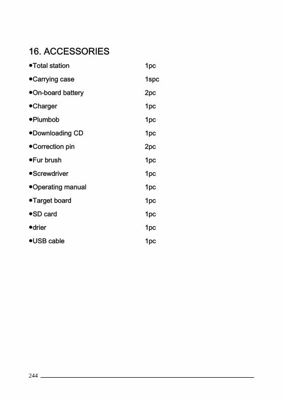
244
16. ACCESSORIES●Total station 1pc
●Carrying case 1spc
●On-board battery 2pc
●Charger 1pc
●Plumbob 1pc
●Downloading CD 1pc
●Correction pin 2pc
●Fur brush 1pc
●Screwdriver 1pc
●Operating manual 1pc
●Target board 1pc
●SD card 1pc
●drier 1pc
●USB cable 1pc