HTP BAY & HTP STANDARD PELLET STOVE OWNER’S MANUAL · HTP BAY & HTP STANDARD PELLET STOVE ....
24
HTP BAY & HTP STANDARD PELLET STOVE OWNER’S MANUAL Installation, Operating and Maintenance Instructions for Pellet Stoves
Transcript of HTP BAY & HTP STANDARD PELLET STOVE OWNER’S MANUAL · HTP BAY & HTP STANDARD PELLET STOVE ....

HTP BAY & HTP STANDARD PELLET STOVE
OWNER’S MANUAL
Installation, Operating and Maintenance Instructions for
Pellet Stoves
Congratulations on your purchase of a HEAT-TECH pellet stove. We at HEAT-TECH take great pride in the quality of our products. We assure you that with proper management, your HEAT-TECH stove will provide you with many years of comfort and enjoyment. Please read this owner’s manual and follow the guidelines thoroughly.
WARNING! READ MANUAL FULLY BEFORE INSTALLATION AND OPERATION.
Page 1
FOR SERVICE AND REPAIR
DEALER:
ADDRESS:
PHONE: ( )

Table of Contents INTRODUCTION .............................................................................................. 3 SPECIFICATIONS/FEATURES ............................................................................ 3
SAFETY FEATURES ...................................................................................................... 3 GOVERNMENT LISTINGS ............................................................................................. 3
INSTALLATION ................................................................................................ 4 WARNINGS AND PRECAUTIONS ................................................................................. 4 CLEARANCES .............................................................................................................. 5 EXHAUST HORIZONTALLY THROUGH A WALL ............................................................. 6 EXHAUST VERTICALLY THROUGH A CEILING ............................................................... 6 INSERT INSTALLATION ................................................................................................ 7 MOBILE HOME INSTALLATION.................................................................................... 8 ELECTRICAL INSTALLATION ......................................................................................... 9 THERMOSTAT INSTALLATION ..................................................................................... 9
OPERATION .................................................................................................. 11 OPERATION WARNINGS AND PRECAUTIONS ............................................................ 11 BASIC OPERATION .................................................................................................... 12 SHUT DOWN PROCEDURES ...................................................................................... 13
MAINTENANCE ............................................................................................. 14 ASH REMOVAL .......................................................................................................... 14 CLEANING AND SERVICING ....................................................................................... 14
TROUBLE SHOOTING .................................................................................... 16 Stove shuts off and the #2 light flashes .................................................................... 16 Stove shuts off and the #3 light flashes .................................................................... 17 Pellets do not ignite ................................................................................................. 17 Home smells of smoke ............................................................................................. 18 Convection blower shuts off and on ......................................................................... 18 Feed light on but pellets not feeding ........................................................................ 18 Glass soots up quickly, flame is lazy/dark/has black tips, burnpot overfills .............. 19 High limit switch keeps tripping ............................................................................... 19 Smoke smell or soot buildup .................................................................................... 20
DIAGRAMS ................................................................................................... 21 WARRANTY................................................................................................... 23
Page 2

INTRODUCTION
This stove has been independently tested and approved in accordance with the specifications and procedures outlined by Underwriters Laboratories, Inc. standards for safety UL 1482, UL 907 solid fuels type room heater, April 1987, and HUD requirements for installation as a stove heater and insert for masonry or metal fireplaces, plus Oregon’s rules for mobile homes (814-23- 900 through 814-23-9090).
This appliance is designed specifically for use only with pelletized wood. It is approved for residential installation according to current national and local building codes when installed on a hearth of masonry or metal fireplace. It is also approved as a mobile home heater and is designed for connection with an outside air source.
This stove will NOT operate using a natural draft, or without an electrical power source for the blower and fuel system.
SPECIFICATIONS/FEATURES
SAFETY FEATURES
If there is a power outage longer than a few seconds, the auger will no longer operate once the power is restored. This prevents pellets from being fed to a non-burning burnpot. Pressing the start button will reactivate the auger feed mode. The blowers will come on when the power is restored to evacuate the combustion chamber gases.
GOVERNMENT LISTINGS
Tested and listed with Myren Consulting INC. of Colville, WA. EPA approved and listed with the Underwriters Laboratory standards.
Page 3

INSTALLATION
WARNINGS AND PRECAUTIONS:
Installation should be done by your qualified dealer or approved stove installer in order to meet all federal, state, and local codes for pellet burning appliances. Improper installation or operation may result in a house fire. Care must be taken not to interfere with the structural integrity of the building.
All local building and fire codes MUST be strictly adhered to. A permit must be obtained by the home owner, at the home owner’s expense, prior to installation.
Check all equipment for damage, possibly caused by shipping. The stove should be burn-tested in a well-ventilated area for at least one hour according to operation instructions. This will cure the paint and season the stove’s metal. (Your stove dealer may have already done this). NOTE: Minor smoking and steaming is normal during the curing process.
Use only listed and approved stovepipe designed for use with pellet stove. Follow pipe manufacturer’s installation instructions. Do not use single wall pipe to vent exhaust from the stove. Approved metal tube is required between the air intake tube and the outside fitting on fresh air intakes.
Care must be taken to maintain minimum clearances to combustibles as per local building codes, fire codes and the safety listing tag on the back of the stove. Use non-combustible 3/8” minimum hearth pads.
The Heat Tech HTP 26 pellet insert has been tested and listed for installation into masonry fireplaces and factory-built “zero clearance” fireplaces.
The purchaser must return the warranty card to validate the warranty.
When the stove is not used for long periods, for example summer months, the stove should be cleaned and free of ash.
Page 4

CLEARANCES Your Heat Tech freestanding stove has 3” clearances to combustibles on back and sides.
The hearth pad must extend out a minimum of 3” from the stove on each side and a minimum of 6” in front of the door.
Page 5

EXHAUST HORIZONTALLY THROUGH A WALL
Position the stove, adhering to clearances. • Locate position of hole in wall, directly behind stove’s exhaust vent. • Cut an opening in the wall: 9 5/8” round for 3” vent or 10 5/8” for 4”
vent. This provides space for the wall thimble. • After exiting exhaust pipe through the wall, you should install 3’
vertical rise to evacuate exhaust gases in case of power outage. Attach end cap and seal outside wall thimble with non-hardening
water proof mastic.
EXHAUST VERTICALLY THROUGH A CEILING
• Locate exhaust pipe location at the rear of the stove. Drop a plumb- bob to the center of the exhaust pipe at the rear of the stove with clean-out “T” installed. Mark center point on the ceiling. Cut a square hole in ceiling, to accommodate fire-stop support assembly: 9 5/8” square hole for 3” or 10 5/8” square hole for 4”.
Connect chimney section from stove upwards. When the pipe passes through the fire-stop at the ceiling, tighten bolts
and clamp around pipe. • Always maintain 3” clearances from combustible materials, when
passing though additional floors or ceilings. Always install fire-stop spacers.
• After lining up the hole in the roof, always 3” larger than the pipe all the way around, install upper edge and sides of flashing under roof materials. Nail to roof on top edge under roof material. DO NOT NAIL ON LOWER EDGE.
Seal nail heads with sealant or mastic. Apply a non-hardening, waterproof mastic where the storm collar will
meet the vent pipe. Slide storm collar down until it sits on flashing. Put on a cap and twist to lock.
Page 6
INSERT INSTALLATION
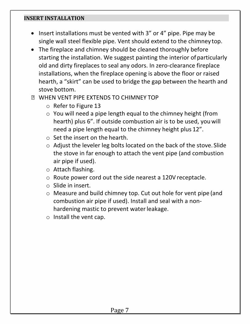
• Insert installations must be vented with 3” or 4” pipe. Pipe may be single wall steel flexible pipe. Vent should extend to the chimney top.
• The fireplace and chimney should be cleaned thoroughly before starting the installation. We suggest painting the interior of particularly old and dirty fireplaces to seal any odors. In zero-clearance fireplace installations, when the fireplace opening is above the floor or raised hearth, a “skirt” can be used to bridge the gap between the hearth and stove bottom.
WHEN VENT PIPE EXTENDS TO CHIMNEY TOP o Refer to Figure 13 o You will need a pipe length equal to the chimney height (from
hearth) plus 6”. If outside combustion air is to be used, you will need a pipe length equal to the chimney height plus 12”.
o Set the insert on the hearth. o Adjust the leveler leg bolts located on the back of the stove. Slide
the stove in far enough to attach the vent pipe (and combustion air pipe if used).
o Attach flashing. o Route power cord out the side nearest a 120V receptacle. o Slide in insert. o Measure and build chimney top. Cut out hole for vent pipe (and
combustion air pipe if used). Install and seal with a non- hardening mastic to prevent water leakage.
o Install the vent cap.
Page 7

MOBILE HOME INSTALLATION SPECIAL MOBILE HOME REQUIREMENTS:
Mobile home installations made prior to the sale of the mobile home are governed by U.S. Department of Housing and Urban Development (HUD) standards. They include the following:
Do not install in a sleeping room Stove should be grounded with a #8 copper wire and terminated with a N.E.C.
approved grounding device Stove should be attached to mobile home during shipment
The combustion air supply for mobile home installations must be connected to an outside source of combustion air. A 1 ¾” inside diameter metallic pipe, either flexible or rigid, must be used when outside air is to be connected. It attaches to the combustion air outlet at the rear of the stove and is terminated outside to wind hood or turned down at 90 degrees to prevent back draft. Outside air can also be channeled through the floor under the stove and through the pedestal and into the firebox. SOURCES OF OUTSIDE AIR FOR FIREPLACES:
Ash clean out through floor of fireplace to outside ash clean out door. Always plug excess opening in ash doors with fiberglass insulation or sheet metal to reduce draft to inside of fireplace that will chill air for convection air supply
Hole can be drilled out through rear of fireplace wall, when fireplace is located on an outside wall.
• Top of chimney along side of exhaust. Remember that the length of the intake tube should remain as short as possible of size up the air intake pipe to 2” or 2½” pipe.
SOURCES OF OUTSIDE AIR FOR FREE STANDING STOVE: Hole in floor at rear of stove to accommodate outside air pipe. Hole in wall at rear of stove to accommodate air pipe. Hole in floor under the pedestal (see figure).
Page 8
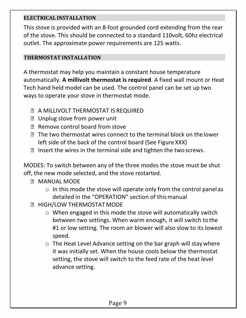
ELECTRICAL INSTALLATION
This stove is provided with an 8-foot grounded cord extending from the rear of the stove. This should be connected to a standard 110volt, 60hz electrical outlet. The approximate power requirements are 125 watts.
THERMOSTAT INSTALLATION A thermostat may help you maintain a constant house temperature automatically. A millivolt thermostat is required. A fixed wall mount or Heat Tech hand held model can be used. The control panel can be set up two ways to operate your stove in thermostat mode.
A MILLIVOLT THERMOSTAT IS REQUIRED Unplug stove from power unit Remove control board from stove The two thermostat wires connect to the terminal block on the lower
left side of the back of the control board (See Figure XXX) Insert the wires in the terminal side and tighten the two screws.
MODES: To switch between any of the three modes the stove must be shut off, the new mode selected, and the stove restarted.
MANUAL MODE o In this mode the stove will operate only from the control panel as
detailed in the “OPERATION” section of this manual HIGH/LOW THERMOSTAT MODE
o When engaged in this mode the stove will automatically switch between two settings. When warm enough, it will switch to the #1 or low setting. The room air blower will also slow to its lowest speed.
o The Heat Level Advance setting on the bar graph will stay where it was initially set. When the house cools below the thermostat setting, the stove will switch to the feed rate of the heat level advance setting.
Page 9

ON/OFF THERMOSTAT MODE o In this mode when the home is warm enough the stove will shut
off. The fans will continue to run until the stove cools. o When the home cools below the thermostat setting, the stove
will automatically restart and run at the last feed rate setting. NOTE: When in “high/low” or “on/off” thermostat mode, do not operate the stove higher than the #3 setting.
Page 10
OPERATION
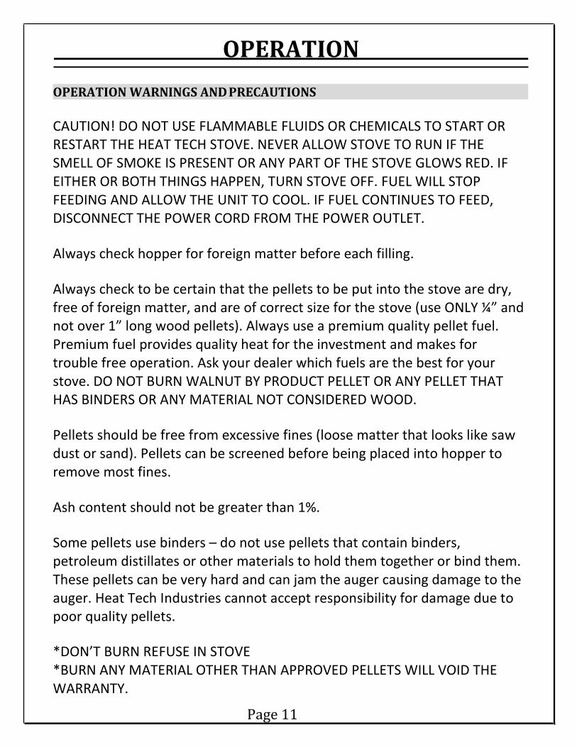
OPERATION WARNINGS AND PRECAUTIONS CAUTION! DO NOT USE FLAMMABLE FLUIDS OR CHEMICALS TO START OR RESTART THE HEAT TECH STOVE. NEVER ALLOW STOVE TO RUN IF THE SMELL OF SMOKE IS PRESENT OR ANY PART OF THE STOVE GLOWS RED. IF EITHER OR BOTH THINGS HAPPEN, TURN STOVE OFF. FUEL WILL STOP FEEDING AND ALLOW THE UNIT TO COOL. IF FUEL CONTINUES TO FEED, DISCONNECT THE POWER CORD FROM THE POWER OUTLET.
Always check hopper for foreign matter before each filling.
Always check to be certain that the pellets to be put into the stove are dry, free of foreign matter, and are of correct size for the stove (use ONLY ¼” and not over 1” long wood pellets). Always use a premium quality pellet fuel. Premium fuel provides quality heat for the investment and makes for trouble free operation. Ask your dealer which fuels are the best for your stove. DO NOT BURN WALNUT BY PRODUCT PELLET OR ANY PELLET THAT HAS BINDERS OR ANY MATERIAL NOT CONSIDERED WOOD.
Pellets should be free from excessive fines (loose matter that looks like saw dust or sand). Pellets can be screened before being placed into hopper to remove most fines.
Ash content should not be greater than 1%.
Some pellets use binders – do not use pellets that contain binders, petroleum distillates or other materials to hold them together or bind them. These pellets can be very hard and can jam the auger causing damage to the auger. Heat Tech Industries cannot accept responsibility for damage due to poor quality pellets.
*DON’T BURN REFUSE IN STOVE *BURN ANY MATERIAL OTHER THAN APPROVED PELLETS WILL VOID THE WARRANTY.
Page 11

Gasket materials should be checked for normal wear or damage annually. Replace gasket material if damaged or worn. Contact your local dealer or Heat Tech for proper size and instructions.
Maintain proper ventilation. It is important that adequate oxygen be supplied to the fire for the combustion process. Modern houses are often so well insulated, it may be necessary to open a window or install an outside air vent to provide a sufficient combustion process.
Since heating with a solid fuel fire is potentially hazardous, even in a well made and thoroughly tested stove, it would be wise to install strategically placed smoke detectors and have a fire extinguisher in a convenient location.
Do not permit operation by young children or those unfamiliar with the stove’s operation.
Do not add more fuel to the burn pot than the automatic fuel system provides, as this could cause an over-firing condition.
Do not service this appliance without disconnecting power cord.
If during start-up or operation you notice a smoldering firepot and heavy smoke build up in the firebox with no visible fire or hot embers, turn off the unit and do not tamper with controls. Wait 15 minutes or until firebox clears, then open the door to clear the burn pot. Turn on stove and restart.
BASIC OPERATION
Before filling the hopper, check for foreign objects. Fill only with ¼” and not over 1” wood pellets. Close hopper lid.
Your Heat Tech pellet stove comes equipped with an automatic igniter, simply turn on the power switch. Your stove will immediately begin feeding pellets, and will light in 5-10 minutes. NOTE: For your automatic igniter to work properly, you must keep the burn pot clear of ash and the burn pot must be pushed tight against the back wall.
Page 12

SHUT DOWN PROCEDURES Turning the Heat Tech pellet stove off is simply a matter of turning the control panel switch to OFF. The blowers will continue to operate until the internal firebox temperatures have fallen to a preset level.
Page 13
MAINTENANCE
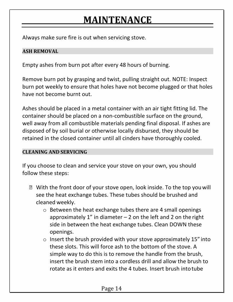
Always make sure fire is out when servicing stove.
ASH REMOVAL
Empty ashes from burn pot after every 48 hours of burning.
Remove burn pot by grasping and twist, pulling straight out. NOTE: Inspect burn pot weekly to ensure that holes have not become plugged or that holes have not become burnt out.
Ashes should be placed in a metal container with an air tight fitting lid. The container should be placed on a non-combustible surface on the ground, well away from all combustible materials pending final disposal. If ashes are disposed of by soil burial or otherwise locally disbursed, they should be retained in the closed container until all cinders have thoroughly cooled.
CLEANING AND SERVICING
If you choose to clean and service your stove on your own, you should follow these steps:
With the front door of your stove open, look inside. To the top you will
see the heat exchange tubes. These tubes should be brushed and cleaned weekly. o Between the heat exchange tubes there are 4 small openings
approximately 1” in diameter – 2 on the left and 2 on the right side in between the heat exchange tubes. Clean DOWN these openings.
o Insert the brush provided with your stove approximately 15” into these slots. This will force ash to the bottom of the stove. A simple way to do this is to remove the handle from the brush, insert the brush stem into a cordless drill and allow the brush to rotate as it enters and exits the 4 tubes. Insert brush into tube
Page 14

and run drill in forward position until drill contacts tube. Note: Only run drill in forward position. DO NOT reverse drill to pull brush out of tubes.
• Next, close the front door of the stove. Notice under the door there is a plate the full width of the stove held on by 2 or 3 screws. Remove the plate and clear any ash behind it. This can be done by inserting a small vacuum hose into the slots. Use a flashlight to make sure bottom is completely vacuumed out.
• At the end of each burn season, the stove should be completely and cleaned and serviced. This is done by removing the back of the stove and oiling the motors that need servicing. At this time, the internal components should be thoroughly cleaned to prevent corrosion caused by moisture.
• SERVICING TIPS: o Always contact your dealer for information on the stove
operation. o A clean stove and exhaust will always give more efficient and
trouble-free operation. o Always unplug the stove before working on the electrical system
and servicing the stove.
Page 15

Stove shuts off and the #2 light flashes
TROUBLE SHOOTING
When your stove is not functioning properly, use this guide to identify and correct common simple problems. Most problems can be solved by following the instructions indicated. If problems continue, or for problems not addressed in this guide, contact your dealer for assistance.
WARNING: UNPLUG STOVE FIRST WHEN POSSIBLE!
COMMON CAUSES INSTRUCTIONS TO CORRECT PROBLEM
Airflow switch hose or stove attachment pipes for hose is/are blocked
Unhook hose from the airflow switch and blow through it. If air flows freely, the hose and tube are fine. If air will not flow through the hose, use a wire coat hanger to clear the blockage.
Components are blocked with ash or foreign material
Follow cleaning instructions in the “Maintenance” section for cleaning air inlet, burnpot, blower, interior air chambers and exhaust pipe.
Firebox is not sealed properly
Check that the door is closed completely. Check that the door gasket is intact and installed properly. If your stove has an ash drawer, ensure that it is properly closed and that the gasket is intact. If you stove has a small hole under the burnpot for ashes, check that the slider plate is in place to seal off the firebox floor.
Ventilation pipe is not installed properly Check that the vent pipe is installed according to the instructions in the “Installation” section.
Bad wire connections to the airflow switch Check that the connections of the grey wires to the airflow switch are intact and properly wired.
Bad wire connections at the Molex connector (on wiring harness)
Check that the connections of the grey wires to the Molex connector are intact and properly wired.
Combustion blower not functioning
If the combustion blower does not function when the stove is on, check for power to the combustion blower. If power is running to the combustion blower, the blower is malfunctioning. If power is not running to the combustion blower, see “combustion blower not receiving power” below.
Combustion blower not receiving power Check that all wire connections are intact and properly wired. If they are, the control board is malfunctioning.
Air switch not receiving power
After the stove has been running for at least 30 seconds, check that a current is running to the air switch (approximately 5 volts). If current is running to the air switch, it may be malfunctioning – see “air switch not functioning” below.
Air switch not functioning (rare)
Follow these steps to test the air switch: 1) First check that airflow switch hose is not
blocked (see “airflow switch hose or stove attachment pipes for hose is/are blocked” above)
2) Disconnect the air hose from the body of the stove
3) With the other end still attached to the air switch, very gently suck on the loose end of the hose – Caution: too much suction can damage the air switch!
If no click is heard, the air switch is malfunctioning.
Page 16

Stove shuts off and the #3 light flashes COMMON CAUSES INSTRUCTIONS TO CORRECT PROBLEM
The hopper is empty
Refill the hopper with approved pellet fuel See “Maintenance” section for specifications of approved pellet fuel
The burnpot is not pushed completely to the rear of the firebox
Make sure that the air intake collar on the burnpot is touching the rear wall of the firebox.
The burnpot holes are blocked Remove the burnpot and thoroughly clean it. The air inlet, the interior chambers, or exhaust system has a partial blockage
Follow all cleaning procedures in the maintenance section of this manual.
The auger shaft is jammed
Empty the hopper and remove the auger pin to remove the auger motor. After removing the auger shaft inspection plate, you will be able to see the auger shaft. Lift the shaft straight up carefully to remove it from the bottom auger bushing. Remove the two nuts holding the top auger biscuit in then lift the shaft out of the stove by rotating the bottom end towards you while lifting the shaft. Inspect the auger shaft and auger tube for damage or burrs and remove any foreign material.
The auger motor has failed
Empty the hopper and remove the auger pin to remove the auger motor. Run the unit. If the motor turns, then the shaft is jammed. If the motor does not turn, then the motor is bad.
The Proof of Fire thermodisk has malfunctioned
Unplug the stove. Temporarily bypass the Proof of Fire thermodisk by disconnecting the two brown wires and connecting them with a short piece of wire. Plug the stove back in. If the stove works, the Proof of Fire thermodisk is bad and must be replaced. WARNING: DO NOT LEAVE THE PROOF OF FIRE THERMODISK BYPASSED! If it remains bypassed, the blowers will never shut off and the auger will continue to feed pellets until the hopper is empty even if the fire goes out.
The high limit thermodisk has tripped or is defective
Wait for the stove to cool for about 30 – 45 minutes. It should now function normally. If not use the owner’s manual to locate the high limit thermodisk. To test if the thermodisk is bad, you can bypass it as described previously for the POF thermodisk.
The fuse on the control board has blown
Remove the control board. On the back there is one fuse. If it appears to be bad, replace it with a 5 amp 250 Volt fuse. Plug the stove back in and try to run the unit.
The control board is not sending power to the Proof of Fire thermodisk or other auger system components
There should be a 5-Volt (approximately) current going to the POF thermodisk after the stove has been on for 10 minutes.
COMMON CAUSES INSTRUCTIONS TO CORRECT PROBLEM
Blockage in igniter tube or inlet for igniter tube
Find the igniter housing on the backside of the firewall. The air intake hole is a small hole located on bottom side of the housing. Make sure it is clear. Also look from the front of the stove to make sure there is not any debris around the igniter element inside of the igniter housing.
The burnpot is not pushed completely to the rear of the firebox.
Make sure that the air intake collar on the burnpot is touching the rear wall of the firebox.
Bad igniter element Put power directly to the igniter element. Watch the tip
Page 17
Pellets do not ignite

Home smells of smoke
Convection blower shuts off and on
Feed light on but pellets not feeding
of the igniter from the front of the stove. After about 2 minutes the tip should glow. If it does not, the element is bad.
The control board is not sending power to the igniter
Check the voltage going to the igniter during startup. It should be a full current. If the voltage is lower than full current, check the wiring. If the wiring checks out good, the board is bad.
COMMON CAUSES INSTRUCTIONS TO CORRECT PROBLEM
There is a leak in the vent pipe system
Inspect all vent pipe connections. Make sure they are sealed with RTV silicone that has a temperature rating of 500 degrees F or higher. Also, seal joints with UL-181-AP foil tape. Also, make sure the square to round adapter piece on the combustion blower has been properly sealed with the same RTV.
The gasket on the combustion blower has gone bad Inspect both gaskets on the combustion blower to make sure they are in good shape.
COMMON CAUSES INSTRUCTIONS TO CORRECT PROBLEM The convection blower is overheating and tripping the internal temperature shutoff.
Clean any dust off of the windings and fan blades. If cleaning the blower does not help, it may be bad.
Circuit board malfunction
Test the current going to the convection blower. If there is power being sent to the blower when it is shut off, then the control board is fine. If there is NOT power being sent to the blower when it shuts off during operation, then you have a bad control board.
COMMON CAUSES INSTRUCTIONS TO CORRECT PROBLEM
Fuse on control board blew Remove the control board. On the back there is one fuse. If it appears to be bad, replace it with a 5 amp 250 Volt fuse. Plug the stove back in and try to run the unit.
High limit switch has tripped or is defective
Wait for the stove to cool for about 30 – 45 minutes. It should now function normally. If not, use the owner’s manual to locate the high limit thermodisk. To test if the thermodisk is bad, you can bypass it as described previously for the POF thermodisk.
Bad auger motor
Remove the auger motor from the auger shaft and try to run the unit. If the motor will turn, the shaft is jammed on something. If the motor will not turn, the motor is bad.
Auger jam
Always unplug stove first. Clean all of the pellets out of the hopper. Then vacuum remaining pellets out of the auger at the bottom of the auger. With a pair of pliers, reach down and grab the auger blade and first see if you can wiggle it back and forth to unjam the auger. If auger is still jammed, from the back of the stove, remove the 1/4“ bolts from each side of the auger housing located just above the auger motor. You can then remove the auger assembly by gently tapping and
Page 18

Glass soots up quickly, flame is lazy/dark/has black tips, burnpot overfills
High limit switch keeps tripping
twisting downward on the auger motor. This will empty the auger housing, thus unjamming the auger. After you have removed the shaft, inspect it for bent flights, burrs, or broken welds. Remove any foreign material that might have caused the jam. Also, check the auger tube for signs of damage such as burrs, rough spots, or grooves cut into the metal that could have caused a jam. Reverse steps to reinstall auger assembly.
Loose wire or connector Check all wires and connectors that connector to the auger motor, high limit switch, and the Molex connector.
Bad control board
If the fuse is good, the wires and connectors check out good, and the high limit switch did not trip, test for power going to the auger motor. If there is not a full current going to the auger motor when the fuel feed light is on, you have a bad control board.
COMMON CAUSES INSTRUCTIONS TO CORRECT PROBLEM Stove or vent pipe is dirty, which restricts airflow through the burnpot
Follow all cleaning procedure in the maintenance section of the owner’s manual.
Vent pipe installed improperly Check to make sure the vent pipe has been installed according to the criteria in the owner’s manual.
Burnpot holes are blocked Remove the burnpot and thoroughly clean it.
Circuit board malfunction
Time the fuel feed light at each setting (after the stove has completed the startup cycle). Make sure the times match the auger timing chart. If the auger motor runs constantly, the board is bad.
Combustion blower is not spinning fast enough Test the RPM on the blower after the blades have been cleaned. The RPM should be approximately 3000 RPM.
Bad pellets (applies to “GLASS SOOTS UP QUICKLY” only)
The brand of pellets or the batch of pellets that are being used may be of poor quality. If possible, try a different brand of pellets. You might also want to try a brand that is made from a different type of wood (softwood vs hardwood). Different woods have different characteristics when being burned.
The trim setting on the low feed rate is too low (applies to “GLASS SOOTS UP QUICKLY” only)
Use the “Reset Trim” button to increase the low feed rate setting. If the 1 & 3 lights are on, the stove is currently on the lowest setting. If only the 1 light is on, the stove is in the default (medium) setting. If the 1 & 4 lights are on, the stove is in the high trim setting for the low feed rate. If the stove is being burned on one of the two lower settings, advance to the next trim setting and try burning the stove.
COMMON CAUSES INSTRUCTIONS TO CORRECT PROBLEM The convection blower is overheating and tripping the internal temperature shutoff
Clean any dust off of the windings and fan blades. If cleaning the blower does not help, it may be bad.
The stove is being left on the highest setting for extended periods of time
The highest heat level setting is designed for use over short periods of time. Burning the stove on the highest setting for longer than 1 -2 hours could lead to potential overheating situations.
Fuel other than wood pellets is being burned in the stove Heat Tech pellet stoves are designed and tested to use wood pellets. While it is possible to burn a corn mixture
Page 19

(corn mixed in with wood pellets) in the stove, it is not recommended to burn above the number 3 heat level. Check for signs of fuel other than wood pellets. If there are signs of corn being used, find out what mix was being used and what setting. No other types of fuel have been approved for Heat Tech pellet stoves. If there are signs of other types of fuel being used, advise the consumer to stop using them immediately.
Power surge or brown out situation
A power surge, spike, or voltage drop could cause the high limit switch to trip. Check to see if a surge protector is being used on the stove. If not, recommend one to the consumer.
High limit switch is malfunctioning If the other items check out ok, replace the high limit switch.
Smoke smell or soot buildup Because it is a wood burning device, your Heat Tech stove may emit a faint wood burning odor. If this increases beyond normal, or if you notice an unusual soot build-up on walls or furniture, check your exhaust system carefully for leaks. All joints should be properly sealed. Also clean your stove, following instructions in “MAINTENANCE”. If problem persists, contact your dealer
Page 20

DIAGRAMS
Page 21

Page 22
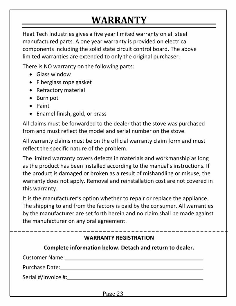
WARRANTY Heat Tech Industries gives a five year limited warranty on all steel manufactured parts. A one year warranty is provided on electrical components including the solid state circuit control board. The above limited warranties are extended to only the original purchaser.
There is NO warranty on the following parts: • Glass window • Fiberglass rope gasket • Refractory material • Burn pot • Paint • Enamel finish, gold, or brass
All claims must be forwarded to the dealer that the stove was purchased from and must reflect the model and serial number on the stove.
All warranty claims must be on the official warranty claim form and must reflect the specific nature of the problem.
The limited warranty covers defects in materials and workmanship as long as the product has been installed according to the manual’s instructions. If the product is damaged or broken as a result of mishandling or misuse, the warranty does not apply. Removal and reinstallation cost are not covered in this warranty.
It is the manufacturer’s option whether to repair or replace the appliance. The shipping to and from the factory is paid by the consumer. All warranties by the manufacturer are set forth herein and no claim shall be made against the manufacturer on any oral agreement.
WARRANTY REGISTRATION
Complete information below. Detach and return to dealer.
Customer Name:
Purchase Date:
Serial #/Invoice #:
Page 23