
HT 800 WP - Guhring, Inc. · HT 800 WP The interchangeable insert drilling system For extreme...
32
HT 800 WP The interchangeable insert drilling system For extreme process reliability From hole diameter 11 to 40.0 mm (0.433 - 1.575 in.) For drilling depths 1.5xD, 3xD, 5xD, 7xD and 10xD With interchangeable inserts for steel, stainless steel, cast iron and Al Holders/interchangeable inserts for pilot drilling/countersinking NEW Larger Diameter Range
-
Upload
truongdung -
Category
Documents
-
view
220 -
download
0
Transcript of HT 800 WP - Guhring, Inc. · HT 800 WP The interchangeable insert drilling system For extreme...

HT 800 WP The interchangeable insert drilling system
For extreme process reliability
From hole diameter 11 to 40.0 mm (0.433 - 1.575 in.)
For drilling depths 1.5xD, 3xD, 5xD, 7xD and 10xD
With interchangeable inserts for steel, stainless steel, cast iron and Al
Holders/interchangeable inserts for pilot drilling/countersinking
NEW Larger Diameter Range

2 HT 800 WP
HT 800 WP and power engineering
The ideal drilling system for the production of large, highly accurate holes in a variety of materials for wind and water power stations, engine plants or gas/steam turbines

6668
77
14
323436384042
HT 800 WP - Overview
INSERTS
INSERT HOLDERS
ACCESSORIES
TROUBLESHOOTING
TECHNICAL
27
21

4 HT 800 WP
A D
C
B
HT 800 WP - Technology and Advantages
With the new HT 800 WP interchangeable drilling system Guhring provides high-performance and cost-efficient holders for holes in diameters 11.00 to 40.0 mm (0.433 - 1.575 in.) These drills excel thanks to the following advantages:
Extended tool life
Optimized chip flow
Perfect cooling lubrication
Highly accurate and rigid insert seat
Rigid holders
A
B
C
D

HT 800 WPHTHTHTHTHTHTHTTTTTTTTTTTTTTHHTHTHTHTHTTTTTTHTHTHHTHTTTTH 8888888888888888880000000000000000000000000000000 WWWWWWWWWWWWWWWWWWWWWWWPPPPPPPPPP
HT 800 WP - Application Tips
Diameter range (mm) 11.0 - 12.99 13.0 - 13.99 14.0 - 15.99 16.0 - 17.99 18.0 - 19.99 20.0 - 21.99 22.0 - 25.99 30.0 - 40.00
Thread M3 M4 M6
Torx size
Tightening torque [Nm] 0.80 1.00 1.70 2.70 4.00 6.0 8.00 14.0
Examples of the HT800 WP extended tool life
Guhring no.
Diameter
Coating ® ® ® ® ®
Material group
Material description
Drill. depth [mm] 70
Hole type
Cooling
Coolant
Machine type
vc [m/min] 100 130 80 160
fz [mm]
Tool life [m] 50 30 35 250 120

6 HT 800 WP
4112 4115 4113 4114 4111
7645 7632 7635
® ®
140° 140° 140° 140°
steel stainl. steel cast iron aluminium pilot drilling
P
M
K
N
S
H
HT 800 WP Interchangeable Inserts
Complete compatibility
Technical features and application recommendations
steel cast iron aluminium
P
M
K
N
S
H

7HT 800 WP
14
45º pilot drilling/countersinking
4105 4106 4107 4108 4109 4110
HT 800 WP Interchangeable Insert Holders
Special tools

8 HT 800 WP
HT 800 WP Interchangeable Inserts For Machining Steel
Series 4115 nano-A
Series 4114 bright
Series 4113 FIREX®
Series 4112 nano-FIREX® Drill
Holder SizePilot Drill
Holder SizeDia Dia h b l4
fract. mm mm mm mm EDP No. EDP No. EDP No. EDP No.
11.007.5 4.5 2.1
9041150110000 9041140110000 9041130110000 9041120110000110 110
11.20 9041150112000 9041140112000 9041130112000 904112011200011.50
7.5 4.5
2.1 9041150115000 9041140115000 9041130115000 9041120115000
115 11029/64 11.51 2.1 9041150115100 9041140115100 9041130115100 9041120115100
11.70 2.1 9041150117000 9041140117000 9041130117000 904112011700011.80 2.1 9041150118000 9041140118000 9041130118000 9041120118000
15/32 11.91 2.2 9041150119100 9041140119100 9041130119100 904112011910012.00
7.7 5.0
2.2 9041150120000 9041140120000 9041130120000 9041120120000
120 12012.10 2.2 9041150121000 9041140121000 9041130121000 904112012100012.20 2.2 9041150122000 9041140122000 9041130122000 9041120122000
31/64 12.30 2.2 9041150123000 9041140123000 9041130123000 904112012300012.50
7.7 5.0
2.3 9041150125000 9041140125000 9041130125000 9041120125000
125 12012.60 2.3 9041150126000 9041140126000 9041130126000 9041120126000
1/2 12.70 2.3 9041150127000 9041140127000 9041130127000 904112012700012.80 2.3 9041150128000 9041140128000 9041130128000 904112012800012.90 2.3 9041150129000 9041140129000 9041130129000 904112012900013.00
8.5 5.52.4 9041150130000 9041140130000 9041130130000 9041120130000
130 13033/64 13.10 2.4 9041150131000 9041140131000 9041130131000 904112013100017/32 13.49 2.4 9041150134900 9041140134900 9041130134900 9041120134900
13.50
8.5 5.5
2.4 9041150135000 9041140135000 9041130135000 9041120135000
135 13013.60 2.4 9041150136000 9041140136000 9041130136000 904112013600013.70 2.4 9041150137000 9041140137000 9041130137000 904112013700013.80 2.5 9041150138000 9041140138000 9041130138000 9041120138000
35/64 13.89 2.5 9041150138900 9041140138900 9041130138900 904112013890014.00
9.6 6.0
2.5 9041150140000 9041140140000 9041130140000 9041120140000
140 14014.10 2.5 9041150141000 9041140141000 9041130141000 9041120141000
9/16 14.29 2.6 9041150142900 9041140142900 9041130142900 904112014290014.40 2.6 9041150144000 9041140144000 9041130144000 904112014400014.50
9.6 6.0
2.6 9041150145000 9041140145000 9041130145000 9041120145000
145 14014.60 2.7 9041150146000 9041140146000 9041130146000 9041120146000
37/64 14.68 2.7 9041150146800 9041140146800 9041130146800 904112014680014.70 2.7 9041150147000 9041140147000 9041130147000 904112014700014.80 2.7 9041150148000 9041140148000 9041130148000 904112014800015.00
9.8 6.0
2.7 9041150150000 9041140150000 9041130150000 9041120150000
150 140
19/32 15.08 2.7 9041150150800 9041140150800 9041130150800 904112015080015.10 2.7 9041150151000 9041140151000 9041130151000 904112015100015.20 2.8 9041150152000 9041140152000 9041130152000 904112015200015.30 2.8 9041150153000 9041140153000 9041130153000 9041120153000
39/64 15.48 2.8 9041150154800 9041140154800 9041130154800 904112015480015.50
9.8 6.0
2.8 9041150155000 9041140155000 9041130155000 9041120155000
155 14015.60 2.9 9041150156000 9041140156000 9041130156000 904112015600015.70 2.9 9041150157000 9041140157000 9041130157000 904112015700015.80 2.9 9041150158000 9041140158000 9041130158000 9041120158000
5/8 15.87 2.9 9041150158700 9041140158700 9041130158700 904112015870016.00
11.0 7.02.9 9041150160000 9041140160000 9041130160000 9041120160000
160 16041/64 16.27 3.0 9041150162700 9041140162700 9041130162700 9041120162700
}Carbide inserts with material-specific attributes
Four distinct geometries are available with the HT 800 WP drilling system, and they are completely interchangeable with any style drill body. The unique locating post and set screw design assures quick and accurate tool changes. The high performance insert designs allow for maximum penetration rates that far exceed conventional spade drills or dual insert drill designs.
HT 800 WP
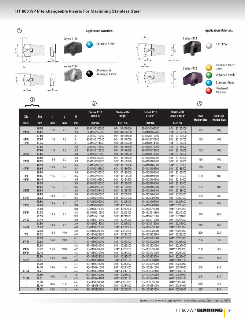
HT 800 WP Interchangeable Inserts For Machining Stainless Steel
Series 4115 nano-A
Series 4114 bright
Series 4113 FIREX®
Series 4112 nano-FIREX® Drill
Holder SizePilot Drill
Holder SizeDia Dia h b l4
fract. mm mm mm mm EDP No. EDP No. EDP No. EDP No.
16.5011.0 7.0
3.0 9041150165000 9041140165000 9041130165000 9041120165000165 160
21/32 16.67 3.0 9041150166700 9041140166700 9041130166700 904112016670017.00
11.0 7.03.1 9041150170000 9041140170000 9041130170000 9041120170000
170 16043/64 17.07 3.1 9041150170700 9041140170700 9041130170700 904112017070011/16 17.46 3.1 9041150174600 9041140174600 9041130174600 9041120174600
17.5011.0 7.0
3.2 9041150175000 9041140175000 9041130175000 9041120175000175 16017.60 3.2 9041150176000 9041140176000 9041130176000 9041120176000
45/64 17.86 3.3 9041150178600 9041140178600 9041130178600 904112017860018.00
12.6 8.03.3 9041150180000 9041140180000 9041130180000 9041120180000
180 18023/32 18.26 3.3 9041150182600 9041140182600 9041130182600 904112018260018.50
12.6 8.03.4 9041150185000 9041140185000 9041130185000 9041120185000
185 18047/64 18.65 3.4 9041150186500 9041140186500 9041130186500 904112018650019.00
12.6 8.03.5 9041150190000 9041140190000 9041130190000 9041120190000
190 1803/4 19.05 3.5 9041150190500 9041140190500 9041130190500 904112019050049/64 19.45 3.5 9041150194500 9041140194500 9041130194500 9041120194500
19.5012.6 8.0
3.5 9041150195000 9041140195000 9041130195000 9041120195000195 18019.60 3.6 9041150196000 9041140196000 9041130196000 9041120196000
25/32 19.84 3.6 9041150198400 9041140198400 9041130198400 904112019840020.00
13.9 9.03.6 9041150200000 9041140200000 9041130200000 9041120200000
200 20051/64 20.24 3.6 9041150202400 9041140202400 9041130202400 904112020240020.50
13.9 9.03.7 9041150205000 9041140205000 9041130205000 9041120205000
205 20013/16 20.64 3.8 9041150206400 9041140206400 9041130206400 904112020640021.00
13.9 9.0
3.8 9041150210000 9041140210000 9041130210000 9041120210000
210 20053/64 21.03 3.8 9041150210300 9041140210300 9041130210300 9041120210300
21.10 3.9 9041150211000 9041140211000 9041130211000 904112021100027/32 21.43 3.9 9041150214300 9041140214300 9041130214300 9041120214300
21.5013.9 9.0
3.9 9041150215000 9041140215000 9041130215000 9041120215000215 20055/64 21.83 4.0 9041150218300 9041140218300 9041130218300 9041120218300
22.0015.3 10.0
4.0 9041150220000 9041140220000 9041130220000 9041120220000220 2207/8 22.22 4.0 9041150222200 9041140222200 9041130222200 9041120222200
22.5015.3 10.0
4.1 9041150225000 9041140225000 9041130225000 9041120225000225 22057/64 22.62 4.1 9041150226200 9041140226200 9041130226200 9041120226200
23.0015.3 10.0
4.2 9041150230000 9041140230000 9041130230000 9041120230000230 22029/32 23.02 4.2 9041150230200 9041140230200 9041130230200 9041120230200
59/64 23.42 4.3 9041150234200 9041140234200 9041130234200 904112023420023.50
15.3 10.04.3 9041150235000 9041140235000 9041130235000 9041120235000
235 22015/16 23.81 4.3 9041150238100 9041140238100 9041130238100 904112023810024.00
15.8 11.04.4 9041150240000 9041140240000 9041130240000 9041120240000
240 24024.10 4.4 9041150241000 9041140241000 9041130241000 904112024100061/64 24.21 4.4 9041150242100 9041140242100 9041130242100 9041120242100
24.5015.8 11.0
4.5 9041150245000 9041140245000 9041130245000 9041120245000245 24031/32 24.61 4.5 9041150246100 9041140246100 9041130246100 9041120246100
25.0015.8 11.0
4.5 9041150250000 9041140250000 9041130250000 9041120250000250 2401 25.40 4.6 9041150254000 9041140254000 9041130254000 9041120254000
25.50 15.8 11.0 4.6 9041150255000 9041140255000 9041130255000 9041120255000 255 240
}Application Materials:
l 4
h
d1
h7
b
Series 4115Stainless Steels
l4
h
d1
h7
b
Series 4114 Aluminum & Aluminum Alloys
Application Materials:
l4
h
d1
m7
bR
Series 4113
Cast Iron
l4
h
d1
h7
b
Series 4112
General Steels/Brass
Universal Steels
Stainless Steels
Hardened Materials

10 HT 800 WP
Series 4115 nano-A
Series 4114 bright
Series 4113 FIREX®
Series 4112 nano-FIREX® Drill
Holder SizePilot Drill
Holder SizeDia Dia h b l4
fract. mm mm mm mm EDP No. EDP No. EDP No. EDP No.
26.00 20.00 12.00 4.80 9041150260000 9041140260000 9041130260000 9041120260000 260 2601 1/32 26.19 20.00 12.00 4.80 9041150261900 9041140261900 9041130261900 9041120261900
26.50 20.00 12.00 4.90 9041150265000 9041140265000 9041130265000 9041120265000 265 2601 3/64 26.59 20.00 12.00 4.90 9041150265900 9041140265900 9041130265900 904112026590027.00 20.00 12.00 5.00 9041150270000 9041140270000 9041130270000 9041120270000 270 26027.50 20.00 12.00 5.10 9041150275000 9041140275000 9041130275000 9041120275000
275 26027.70 20.00 12.00 5.10 9041150277000 9041140277000 9041130277000 90411202770001 3/32 27.78 20.00 12.00 5.10 9041150277800 9041140277800 9041130277800 9041120277800
28.00 20.70 13.00 5.10 9041150280000 9041140280000 9041130280000 9041120280000 280 2801 7/64 28.18 20.70 13.00 5.20 9041150281800 9041140281800 9041130281800 904112028180028.50 20.70 13.00 5.20 9041150285000 9041140285000 9041130285000 9041120285000 285 2801 1/8 28.58 20.70 13.00 5.30 9041150285800 9041140285800 9041130285800 904112028580029.00 20.70 13.00 5.30 9041150290000 9041140290000 9041130290000 9041120290000 290 2801 5/32 29.37 20.70 13.00 5.40 9041150293700 9041140293700 9041130293700 904112029370029.50 20.70 13.00 5.40 9041150295000 9041140295000 9041130295000 9041120295000
295 28029.60 20.70 13.00 5.50 9041150296000 90411202960001 11/64 29.77 20.70 13.00 5.50 9041150297700 9041140297700 9041130297700 9041120297700
30.00 22.30 14.00 5.50 9041150300000 9041140300000 9041130300000 9041120300000 300 3001 3/16 30.16 22.30 14.00 5.60 9041150301600 9041140301600 9041130301600 904112030160030.50 22.30 14.00 5.70 9041150305000 9041140305000 9041130305000 9041120305000 305 3001 7/32 30.96 22.30 14.00 5.70 9041150309600 9041140309600 9041130309600 904112030960031.00 22.30 14.00 5.80 9041150310000 9041140310000 9041130310000 9041120310000 310 30031.50 22.30 14.00 5.80 9041150315000 9041140315000 9041130315000 9041120315000 315 3001 1/4 31.75 22.30 14.00 5.90 9041150317500 9041140317500 9041130317500 904112031750032.00 23.10 15.00 6.00 9041150320000 9041140320000 9041130320000 9041120320000
320 32032.50 23.10 15.00 6.00 9041150325000 9041140325000 9041130325000 9041120325000
1 9/32 32.54 23.10 15.00 6.00 9041150325400 9041140325400 9041130325400 90411203254001 19/64 32.94 23.10 15.00 6.10 9041150329400 9041140329400 9041130329400 9041120329400
33.00 23.10 15.00 6.10 9041150330000 9041140330000 9041130330000 90411203300001 5/16 33.34 23.10 15.00 6.10 9041150333400 9041140333400 9041130333400 9041120333400 330 320
33.50 23.10 15.00 6.20 9041150335000 9041140335000 9041130335000 904112033500034.00 23.10 15.00 6.30 9041150340000 9041140340000 9041130340000 9041120340000
340 3201 11/32 34.13 23.10 15.00 6.30 9041150341300 9041140341300 9041130341300 9041120341300
34.50 23.10 15.00 6.40 9041150345000 9041140345000 9041130345000 90411203450001 3/8 34.93 23.10 15.00 6.40 9041150349300 9041140349300 9041130349300 9041120349300
35.00 23.10 15.00 6.50 9041150350000 9041140350000 9041130350000 904112035000035.50 23.10 15.00 6.60 9041150355000 9041140355000 9041130355000 9041120355000 350 320
1 13/32 35.72 23.10 15.00 6.60 9041150357200 9041140357200 9041130357200 904112035720036.00 23.90 16.00 6.70 9041150360000 9041140360000 9041130360000 904112036000036.50 23.90 16.00 6.70 9041150365000 9041140365000 9041130365000 9041120365000 360 360
1 7/16 36.51 23.90 16.00 6.80 9041150365100 9041140365100 9041130365100 904112036510037.00 23.90 16.00 6.80 9041150370000 9041140370000 9041130370000 9041120370000
1 15/32 37.31 23.90 16.00 6.90 9041150373100 9041140373100 9041130373100 9041120373100 370 36037.50 23.90 16.00 7.00 9041150375000 9041140375000 9041130375000 904112037500038.00 23.90 16.00 7.00 9041150380000 9041140380000 9041130380000 9041120380000
1 1/2 38.10 23.90 16.00 7.00 9041150381000 9041140381000 9041130381000 9041120381000 380 3601 33/64 38.50 23.90 16.00 7.10 9041150385000 9041140385000 9041130385000 9041120385000
39.00 23.90 16.00 7.10 9041150390000 9041140390000 9041130390000 9041120390000390 36039.50 23.90 16.00 7.20 9041150395000 9041140395000 9041130395000 9041120395000
40.00 23.90 16.00 7.30 9041150400000 9041140400000 9041130400000 9041120400000
Carbide inserts with material-specific attributes}

11HT 800 WP
Drill inserts for pilot drilling - Series 4111Carbide, nano-ATM coated
145º point angle, m7 tolerance on diameter
HT 800 WP Interchangeable Insert Drills
The Series 4105 is a pilot and chamfering tool specifically designed for pilot drilling 7xD and especially 10xD deep hole applications. The Series 4111 insert has a 145º point angle which is required for proper application of a pre-drill pilot operation. This pilot drilling insert is also interchangeable with all other HT 800 WP body series.
l 4
h
d1 m
7
bSeries 4111
Series 4111 nano-A insert Drill
Holder Size
Pilot DrillHolder
Size
Dia Dia h b l4
fract. mm mm mm mm EDP No.
11.00 6.9 4.5 1.5 9041110110000110 110
11.20 6.9 4.5 1.5 904111011200011.50 6.9 4.5 1.5 9041110115000
115 11029/64 11.51 6.9 4.5 1.5 9041110115100
11.70 6.9 4.5 1.6 904111011700011.80 6.9 4.5 1.6 9041110118000
15/32 11.91 6.9 4.5 1.6 904111011910012.00 7.1 5.0 1.6 9041110120000
120 12012.10 7.1 5.0 1.6 904111012100012.20 7.1 5.0 1.6 9041110122000
31/64 12.30 7.1 5.0 1.6 904111012300012.50 7.1 5.0 1.7 9041110125000
125 12012.60 7.1 5.0 1.7 9041110126000
1/2 12.70 7.1 5.0 1.7 904111012700012.80 7.1 5.0 1.7 904111012800012.90 7.1 5.0 1.7 904111012900013.00 7.9 5.5 1.7 9041110130000
130 13033/64 13.10 7.9 5.5 1.7 904111013100017/32 13.49 7.9 5.5 1.8 9041110134900
13.50 7.9 5.5 1.8 9041110135000
135 13013.60 7.9 5.5 1.8 904111013600013.70 7.9 5.5 1.8 904111013700013.80 7.9 5.5 1.9 9041110138000
35/64 13.89 7.9 5.5 1.9 904111013890014.00 9.1 6.0 1.9 9041110140000
140 14014.10 9.1 6.0 1.9 9041110141000
9/16 14.29 9.1 6.0 1.9 904111014290014.40 9.1 6.0 1.9 904111014400014.50 9.1 6.0 1.9 9041110145000
145 14014.60 9.1 6.0 2.0 9041110146000
37/64 14.68 9.1 6.0 2.0 904111014680014.70 9.1 6.0 2.0 904111014700014.80 9.1 6.0 2.0 904111014800015.00 9.1 6.0 2.0 9041110150000
150 140
19/32 15.08 9.1 6.0 2.0 904111015080015.10 9.1 6.0 2.0 904111015100015.20 9.1 6.0 2.0 904111015200015.30 9.1 6.0 2.1 9041110153000
39/64 15.48 9.1 6.0 2.1 904111015480015.50 9.1 6.0 2.1 9041110155000
155 14015.60 9.1 6.0 2.1 904111015600015.70 9.1 6.0 2.1 904111015700015.80 9.1 6.0 2.1 9041110158000
5/8 15.87 9.1 6.0 2.1 904111015870016.00 10.2 7.0 2.1 9041110160000
160 16041/64 16.27 10.2 7.0 2.2 904111016270016.50 10.2 7.0 2.2 9041110165000
165 16021/32 16.67 10.2 7.0 2.2 9041110166700
}
Series 4111 nano-A insert Drill
Holder Size
Pilot DrillHolder
Size
Dia Dia h b l4
fract. mm mm mm mm EDP No.
17.00 10.2 7.0 2.3 9041110170000170 16043/64 17.07 10.2 7.0 2.3 9041110170700
11/16 17.46 10.2 7.0 2.3 904111017460017.50 10.2 7.0 2.3 9041110175000
175 16017.60 10.2 7.0 2.3 904111017600045/64 17.86 10.2 7.0 2.4 9041110178600
18.00 11.7 8.0 2.4 9041110180000180 18023/32 18.26 11.7 8.0 2.4 9041110182600
18.50 11.7 8.0 2.5 9041110185000185 18047/64 18.65 11.7 8.0 2.5 9041110186500
19.00 11.7 8.0 2.5 9041110190000190 1803/4 19.05 11.7 8.0 2.5 9041110190500
49/64 19.45 11.7 8.0 2.6 904111019450019.50 11.7 8.0 2.6 9041110195000
195 18019.60 11.7 8.0 2.6 904111019600025/32 19.84 11.7 8.0 2.7 9041110198400
20.00 12.9 9.0 2.7 9041110200000200 20051/64 20.24 12.9 9.0 2.7 9041110202400
20.50 12.9 9.0 2.7 9041110205000205 20013/16 20.64 12.9 9.0 2.8 9041110206400
21.00 12.9 9.0 2.8 9041110210000
210 20053/64 21.03 12.9 9.0 2.8 9041110210300
21.10 12.9 9.0 2.8 904111021100027/32 21.43 12.9 9.0 2.9 9041110214300
21.50 13.9 9.0 3.9 9041110215000215 20055/64 21.83 13.9 9.0 4.0 9041110218300
22.00 14.3 10.0 3.0 9041110220000220 2207/8 22.22 14.3 10.0 3.0 9041110222200
22.50 14.3 10.0 3.0 9041110225000225 22057/64 22.62 14.3 10.0 3.0 9041110226200
23.00 14.3 10.0 3.1 9041110230000230 22029/32 23.02 14.3 10.0 3.1 9041110230200
59/64 23.42 14.3 10.0 3.1 904111023420023.50 14.3 10.0 3.1 9041110235000
235 22015/16 23.81 14.3 10.0 3.2 904111023810024.00 14.7 11.0 3.2 9041110240000
240 24024.10 14.7 11.0 3.2 904111024100061/64 24.21 14.7 11.0 3.2 9041110242100
24.50 14.7 11.0 3.3 9041110245000245 24031/32 24.61 14.7 11.0 3.3 9041110246100
25.00 14.7 11.0 3.4 9041110250000250 2401 25.40 14.7 11.0 3.4 9041110254000
25.50 14.7 11.0 3.4 9041110255000 255 24026.00 19.40 12.00 4.10 9041110260000
260 2601 1/32 26.19 19.40 12.00 4.10 904111026190026.50 19.40 12.00 4.10 9041110265000
265 2601 3/64 26.59 19.40 12.00 4.20 904111026590027.00 19.40 12.00 4.20 9041110270000 270 260

12 HT 800 WP
HT 800 WP Interchangeable Insert Drills
l 4
h
d1 m
7
bSeries 4111
Series 4111 nano-A insert Drill
Holder Size
Pilot DrillHolder
Size
Dia Dia h b l4
fract. mm mm mm mm EDP No.
27.50 19.40 12.00 4.30 9041110275000275 26027.70 19.40 12.00 4.30 9041110277000
1 3/32 27.78 19.40 12.00 4.30 904111027780028.00 20.10 13.00 4.40 9041110280000
280 28028.18 20.10 13.00 4.40 904111028180028.50 20.10 13.00 4.50 9041110285000
285 28028.58 20.10 13.00 4.50 904111028580029.00 20.10 13.00 4.60 9041110290000
290 2801 5/32 29.37 20.10 13.00 4.60 904111029370029.50 20.10 13.00 4.60 9041110295000 295 28030.00 21.70 14.00 4.70 9041110300000
300 3001 3/16 30.16 21.70 14.00 4.70 904111030160030.50 21.70 14.00 4.80 9041110305000
305 30030.96 21.70 14.00 4.80 904111030960031.00 21.70 14.00 4.90 9041110310000 310 30031.50 21.70 14.00 4.90 9041110315000
315 3001 1/4 31.75 21.70 14.00 4.90 904111031750032.00 22.40 15.00 5.00 9041110320000
320 32032.50 22.40 15.00 5.10 90411103250001 9/32 32.54 22.40 15.00 5.10 9041110325400
33.00 22.40 15.00 5.20 9041110330000330 3201 5/16 33.34 22.40 15.00 5.20 9041110333400
33.50 22.40 15.00 5.30 904111033500034.00 22.40 15.00 5.40 9041110340000
340 3201 11/32 34.13 22.40 15.00 5.40 9041110341300
34.50 22.40 15.00 5.40 904111034500034.93 22.40 15.00 5.40 904111034930035.00 22.40 15.00 5.50 9041110350000
350 32035.50 22.40 15.00 5.60 904111035500035.72 22.40 15.00 5.60 904111035720036.00 23.20 16.00 5.70 9041110360000
360 36036.50 23.20 16.00 5.70 904111036500036.51 23.20 16.00 5.70 904111036510037.00 23.20 16.00 5.80 9041110370000
370 3601 15/32 37.31 23.20 16.00 5.80 904111037310037.50 23.20 16.00 5.90 904111037500038.00 23.20 16.00 6.00 9041110380000
380 3601 1/2 38.10 23.20 16.00 6.00 90411103810001 33/64 38.50 23.20 16.00 6.10 9041110385000
39.00 23.20 16.00 6.20 9041110390000390 36039.50 23.20 16.00 6.20 9041110395000
40.00 23.20 16.00 6.20 9041110400000

13HT 800 WP
Series 7645 TiN coated
Series 7632 TiAlN coated
Series 7635 Bright finish
Drill
d s R l Holder Size
Type mm mm mm mm EDP No. EDP No. EDP No.
CPGT050204R 5.56 2.38 0.4 5.64 9076450520400 9076350520400 110-140CPGT060204R 6.35 2.38 0.4 6.45 9076450620400 9076350620400 160-240CPGT09T308R 9.53 3.97 0.8 9.67 9076450930800 9076350930800 300-360CPGW050204 5.56 2.38 0.4 5.60 9076320520400 110-140CPGW060204 6.35 2.38 0.4 6.40 9076320620400 160-240CPGT09T308 9.53 3.97 0.8 9.67 9076320930800 300-360
l
R
d
s80 o
11o
Series 7645 for steels
Series 7632 for cast iron
Series 7635 for aluminum
Countersink inserts for pilot and countersink holes
HT 800 WPwww.GUHRING.com
Guhring Navigator is a step by step program
that allows you to find the perfect Guhring
tool for your machining task.
Guhring Navigator allows you to specify the
material you are cutting and tool features you
desire. The ending search result displays the
ideal tool(s), speeds and feeds as well as
other key information.
Stop flipping through a catalog to find the
right tool and let Guhring Navigator do the
work for you!
g
ing
y the
es you
ys the
as
he
the
Guhring Navigator:

14 HT 800 WP
1 x D for Pilot Drilling and Countersinking
d1Series 4105 Holder (1xD w/countersink)
Holder EDP No. Insert Range d2 d2 d3 l1 l2 l3
Size mm mm in mm mm mm mm
1109041050110000 11.00-11.99 12.00 17.00
81.00 14.80 45.009041050110050 11.00-11.99 12.70 1/2 17.00
1209041050120000 12.00-12.99 12.00 18.00
84.00 15.80 45.009041050120050 12.00-12.99 12.70 1/2 18.00
1309041050130000 13.00-13.99 14.00 18.00
86.00 16.30 45.009041050130050 13.00-13.99 15.875 5/8 18.00
1409041050140000 14.00-15.99 16.00 18.00
93.00 17.40 48.009041050140050 14.00-15.99 15.875 5/8 18.00
1609041050160000 16.00-17.99 18.00 20.00
99.00 19.40 48.009041050160050 16.00-17.99 19.05 3/4 20.00
1809041050180000 18.00-19.99 20.00 22.00
106.00 21.40 50.009041050180050 18.00-19.99 19.05 3/4 22.00
2009041050200000 20.00-21.99 25.00 24.00
117.00 23.40 56.009041050200050 20.00-21.99 25.40 1 24.00
2209041050220000 22.00-23.99 25.00 26.00
122.00 25.40 56.009041050220050 22.00-23.99 25.40 1 26.00
2409041050240000 24.00-25.99 25.00 28.00
128.00 27.40 56.009041050240050 24.00-25.99 25.40 1 28.00
2609041050260000 26.00 - 27.99 32.00 32.00
142.00 28.00 60.009041050260050 26.00 - 27.99 31.75 1 1/4 32.00
2809041050280000 28.00 - 29.99 32.00 34.00
147.00 30.00 60.009041050280050 28.00 - 29.99 31.75 1 1/4 34.00
3009041050300000 30.00 - 31.99 32.00 38.00
152.00 32.00 60.009041050300050 30.00 - 31.99 31.75 1 1/4 38.00
3209041050320000 32.00 - 35.99 32.00 42.00
163.00 36.00 60.009041050320050 32.00 - 35.99 31.75 1 1/4 42.00
3609041050360000 36.00 - 40.00 32.00 46.00
173.00 40.00 60.009041050360050 36.00 - 40.00 31.75 1 1/4 46.00
l2
l1
d2
h6
45o
l4
h
d3
l 3d
1
HT-PlatteArt.-Nr. 4111insert HTno. 4111
2 xinterchangeable insert
Holders for pilot drilling - Series 4105Tool steel, coolant fed, nickel treated
145°
140°
~0,01
# 4111Tol. m7
# 4112/13/14/15
Pilot drilling example
HT 800 WP
HT 800 WP Interchangeable Insert Drills
h
d1
d3
d2 h
6
Shank DIN 6535-HE
l 2
l 4
l 3
l 1
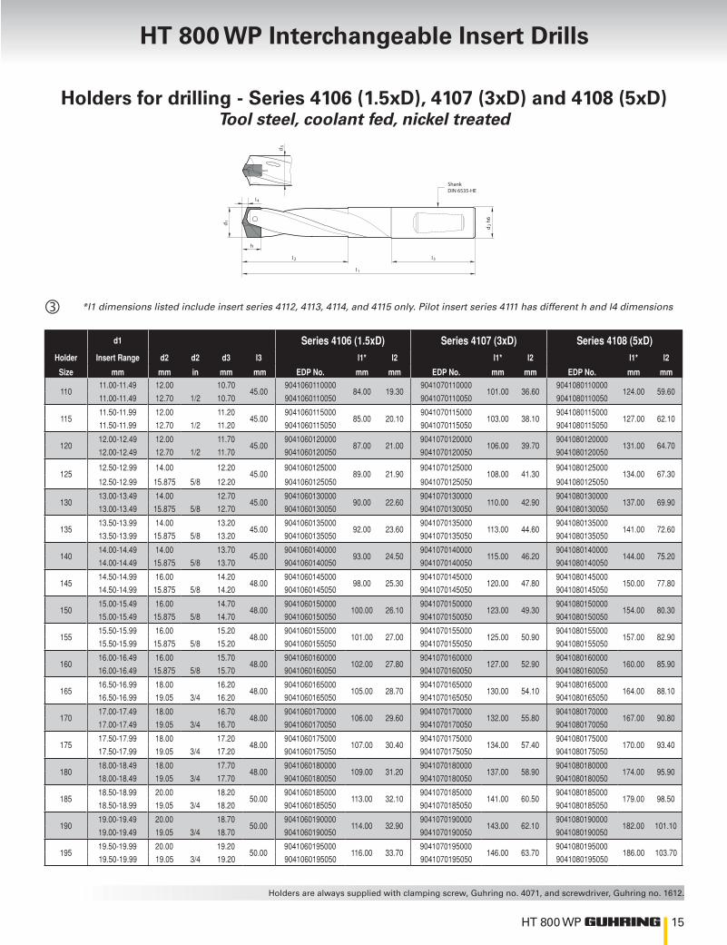
Holders for drilling - Series 4106 (1.5xD), 4107 (3xD) and 4108 (5xD)Tool steel, coolant fed, nickel treated
*l1 dimensions listed include insert series 4112, 4113, 4114, and 4115 only. Pilot insert series 4111 has different h and l4 dimensions
d1 Series 4106 (1.5xD) Series 4107 (3xD) Series 4108 (5xD)Holder Insert Range d2 d2 d3 l3 l1* l2 l1* l2 l1* l2
Size mm mm in mm mm EDP No. mm mm EDP No. mm mm EDP No. mm mm
11011.00-11.49 12.00 10.70
45.009041060110000
84.00 19.309041070110000
101.00 36.609041080110000
124.00 59.6011.00-11.49 12.70 1/2 10.70 9041060110050 9041070110050 9041080110050
11511.50-11.99 12.00 11.20
45.009041060115000
85.00 20.109041070115000
103.00 38.109041080115000
127.00 62.1011.50-11.99 12.70 1/2 11.20 9041060115050 9041070115050 9041080115050
12012.00-12.49 12.00 11.70
45.009041060120000
87.00 21.009041070120000
106.00 39.709041080120000
131.00 64.7012.00-12.49 12.70 1/2 11.70 9041060120050 9041070120050 9041080120050
12512.50-12.99 14.00 12.20
45.009041060125000
89.00 21.909041070125000
108.00 41.309041080125000
134.00 67.3012.50-12.99 15.875 5/8 12.20 9041060125050 9041070125050 9041080125050
13013.00-13.49 14.00 12.70
45.009041060130000
90.00 22.609041070130000
110.00 42.909041080130000
137.00 69.9013.00-13.49 15.875 5/8 12.70 9041060130050 9041070130050 9041080130050
13513.50-13.99 14.00 13.20
45.009041060135000
92.00 23.609041070135000
113.00 44.609041080135000
141.00 72.6013.50-13.99 15.875 5/8 13.20 9041060135050 9041070135050 9041080135050
14014.00-14.49 14.00 13.70
45.009041060140000
93.00 24.509041070140000
115.00 46.209041080140000
144.00 75.2014.00-14.49 15.875 5/8 13.70 9041060140050 9041070140050 9041080140050
14514.50-14.99 16.00 14.20
48.009041060145000
98.00 25.309041070145000
120.00 47.809041080145000
150.00 77.8014.50-14.99 15.875 5/8 14.20 9041060145050 9041070145050 9041080145050
15015.00-15.49 16.00 14.70
48.009041060150000
100.00 26.109041070150000
123.00 49.309041080150000
154.00 80.3015.00-15.49 15.875 5/8 14.70 9041060150050 9041070150050 9041080150050
15515.50-15.99 16.00 15.20
48.009041060155000
101.00 27.009041070155000
125.00 50.909041080155000
157.00 82.9015.50-15.99 15.875 5/8 15.20 9041060155050 9041070155050 9041080155050
16016.00-16.49 16.00 15.70
48.009041060160000
102.00 27.809041070160000
127.00 52.909041080160000
160.00 85.9016.00-16.49 15.875 5/8 15.70 9041060160050 9041070160050 9041080160050
16516.50-16.99 18.00 16.20
48.009041060165000
105.00 28.709041070165000
130.00 54.109041080165000
164.00 88.1016.50-16.99 19.05 3/4 16.20 9041060165050 9041070165050 9041080165050
17017.00-17.49 18.00 16.70
48.009041060170000
106.00 29.609041070170000
132.00 55.809041080170000
167.00 90.8017.00-17.49 19.05 3/4 16.70 9041060170050 9041070170050 9041080170050
17517.50-17.99 18.00 17.20
48.009041060175000
107.00 30.409041070175000
134.00 57.409041080175000
170.00 93.4017.50-17.99 19.05 3/4 17.20 9041060175050 9041070175050 9041080175050
18018.00-18.49 18.00 17.70
48.009041060180000
109.00 31.209041070180000
137.00 58.909041080180000
174.00 95.9018.00-18.49 19.05 3/4 17.70 9041060180050 9041070180050 9041080180050
18518.50-18.99 20.00 18.20
50.009041060185000
113.00 32.109041070185000
141.00 60.509041080185000
179.00 98.5018.50-18.99 19.05 3/4 18.20 9041060185050 9041070185050 9041080185050
19019.00-19.49 20.00 18.70
50.009041060190000
114.00 32.909041070190000
143.00 62.109041080190000
182.00 101.1019.00-19.49 19.05 3/4 18.70 9041060190050 9041070190050 9041080190050
19519.50-19.99 20.00 19.20
50.009041060195000
116.00 33.709041070195000
146.00 63.709041080195000
186.00 103.7019.50-19.99 19.05 3/4 19.20 9041060195050 9041070195050 9041080195050

16 HT 800 WP
Holders
Continued from previous page
d1 Series 4106 (1.5xD) Series 4107 (3xD) Series 4108 (5xD)Holder Insert Range d2 d2 d3 l3 l1* l2 l1* l2 l1* l2
Size mm mm in mm mm EDP No. mm mm EDP No. mm mm EDP No. mm mm
20020.00-20.49 20.00 19.70
50.009041060200000
117.00 34.609041070200000
148.00 65.309041080200000
189.00 106.3020.00-20.49 19.05 3/4 19.70 9041060200050 9041070200050 9041080200050
20520.50-20.99 25.00 20.20
56.009041060205000
128.00 35.509041070205000
159.00 67.009041080205000
201.00 109.0020.50-20.99 25.40 1 20.20 9041060205050 9041070205050 9041080205050
21021.00-21.49 25.00 20.70
56.009041060210000
129.00 36.409041070210000
161.00 68.609041080210000
204.00 111.6021.00-21.49 25.40 1 20.70 9041060210050 9041070210050 9041080210050
21521.50-21.99 25.00 21.20
56.009041060215000
130.00 37.209041070215000
163.00 70.109041080215000
207.00 114.1021.50-21.99 25.40 1 21.20 9041060215050 9041070215050 9041080215050
22022.00-22.49 25.00 21.70
56.009041060220000
131.00 38.009041070220000
165.00 71.709041080220000
210.00 116.7022.00-22.49 25.40 1 21.70 9041060220050 9041070220050 9041080220050
22522.50-22.99 25.00 22.20
56.009041060225000
134.00 38.909041070225000
168.00 73.309041080225000
214.00 119.3022.50-22.99 25.40 1 22.20 9041060225050 9041070225050 9041080225050
23023.00-23.49 25.00 22.70
56.009041060230000
135.00 39.809041070230000
170.00 74.909041080230000
217.00 121.9023.00-23.49 25.40 1 22.70 9041060230050 9041070230050 9041080230050
23523.50-23.99 25.00 23.20
56.009041060235000
137.00 40.609041070235000
173.00 76.509041080235000
221.00 124.5023.50-23.99 25.40 1 23.20 9041060235050 9041070235050 9041080235050
24024.00-24.49 25.00 23.70
56.009041060240000
138.00 41.509041070240000
175.00 78.109041080240000
224.00 127.1024.00-24.49 25.40 1 23.70 9041060240050 9041070240050 9041080240050
24524.50-24.99 25.00 24.20
56.009041060245000
140.00 42.309041070245000
177.00 79.709041080245000
227.00 129.7024.50-24.99 25.40 1 24.20 9041060245050 9041070245050 9041080245050
25025.00-25.49 25.00 24.70
56.009041060250000
142.00 43.209041070250000
180.00 81.309041080250000
231.00 132.3025.00-25.49 25.40 1 24.70 9041060250050 9041070250050 9041080250050
25525.50-25.99 32.00 25.20
60.009041060255000
148.00 44.009041070255000
187.00 82.909041080255000
239.00 134.9025.50-25.99 31.75 1 1/4 25.20 9041060255050 9041070255050 9041080255050
26026.00-26.49 32.00 25.70
60.009041060260000
151.00 44.309041070260000
191.00 84.009041080260000
244.00 137.0026.00-26.49 31.75 1 1/4 25.70 9041060260050 9041070260050 9041080260050
26526.50-26.99 32.00 26.20
60.009041060265000
153.00 45.109041070265000
193.00 86.109041080265000
247.00 140.0026.50-26.99 31.75 1 1/4 26.20 9041060265050 9041070265050 9041080265050
27027.00-27.49 32.00 26.70
60.009041060270000
155.00 46.009041070270000
196.00 87.209041080270000
251.00 142.0027.00-27.49 31.75 1 1/4 26.70 9041060270050 9041070270050 9041080270050
27527.50-27.99 32.00 27.20
60.009041060275000
156.00 46.809041070275000
198.00 88.909041080275000
254.00 144.8027.50-27.99 31.75 1 1/4 27.20 9041060275050 9041070275050 9041080275050
28028.00-28.49 32.00 27.70
60.009041060280000
157.00 47.709041070280000
200.00 90.509041080280000
257.00 147.4028.00-28.49 31.75 1 1/4 27.70 9041060280050 9041070280050 9041080280050
28528.50-28.99 32.00 28.20
60.009041060285000
159.00 48.509041070285000
202.00 92.509041080285000
260.00 150.4028.50-28.99 31.75 1 1/4 28.20 9041060285050 9041070285050 9041080285050

17HT 800 WP
HT 800 WP Interchangeable Insert Drills
h
d1
d3
d2 h
6
Shank DIN 6535-HE
l 2
l 4
l 3
l 1
Continued from previous page
d1 Series 4106 (1.5xD) Series 4107 (3xD) Series 4108 (5xD)Holder Insert Range d2 d2 d3 l3 l1* l2 l1* l2 l1* l2
Size mm mm in mm mm EDP No. mm mm EDP No. mm mm EDP No. mm mm
29029.00-29.49 32.00 28.70
60.009041060290000
161.00 49.409041070290000
205.00 94.609041080290000
264.00 153.5029.00-29.49 31.75 1 1/4 28.70 9041060290050 9041070290050 9041080290050
29529.50-29.99 32.00 29.20
60.009041060295000
162.00 50.209041070295000
207.00 95.109041080295000
267.00 155.1029.50-29.99 31.75 1 1/4 29.20 9041060295050 9041070295050 9041080295050
30030.00-30.49 32.00 29.70
60.009041060300000
164.00 50.909041070300000
210.00 96.709041080300000
271.00 157.6030.00-30.49 31.75 1 1/4 29.70 9041060300050 9041070300050 9041080300050
30530.50-30.99 32.00 30.20
60.009041060305000
166.00 51.709041070305000
212.00 98.309041080305000
274.00 160.2030.50-30.99 31.75 1 1/4 30.20 9041060305050 9041070305050 9041080305050
31031.00-31.49 32.00 30.70
60.009041060310000
167.00 52.609041070310000
214.00 99.809041080310000
277.00 162.8031.00-31.49 31.75 1 1/4 30.70 9041060310050 9041070310050 9041080310050
31531.50-31.99 32.00 31.20
60.009041060315000
168.00 53.409041070315000
216.00 101.409041080315000
280.00 165.4031.50-31.99 31.75 1 1/4 31.20 9041060315050 9041070315050 9041080315050
32032.00-32.99 32.00 31.70
60.009041060320000
172.00 55.109041070320000
221.00 104.609041080320000
287.00 170.6032.00-32.99 31.75 1 1/4 31.70 9041060320050 9041070320050 9041080320050
33033.00-33.99 32.00 32.70
60.009041060330000
175.00 56.809041070330000
226.00 107.809041080330000
294.00 175.8033.00-39.99 31.75 1 1/4 32.70 9041060330050 9041070330050 9041080330050
34034.00-34.99 32.00 33.70
60.009041060340050
178.00 58.509041070340050
230.00 111.009041080340050
300.00 181.0034.00-34.99 31.75 1 1/4 33.70 9041060340050 9041070340050 9041080340050
35035.00-35.99 32.00 34.70
60.009041060350000
181.00 60.209041070350000
235.00 114.209041080350000
307.00 186.2035.00-35.99 31.75 1 1/4 34.70 9041060350050 9041070350050 9041080350050
36036.00-3.99 32.00 35.70
60.009041060360000
184.00 61.809041070360000
240.009041080360000
314.00 191.3036.00-36.99 31.75 1 1/4 35.70 9041060360050 9041070360050 117.30 9041080360050
37037.00-37.99 32.00 36.70
60.009041060370000
188.00 63.509041070370000
245.00 120.509041080370000
321.00 196.5037.00-37.99 31.75 1 1/4 36.70 9041060370050 9041070370050 9041080370050
38038.00-38.99 32.00 37.70
60.009041060380000
191.00 65.209041070380000
249.00 123.709041080380000
327.00 201.7038.00-38.99 31.75 1 1/4 37.70 9041060380050 9041070380050 9041080380050
39039.00-40.00 32.00 38.70
60.009041060390000
194.00 66.909041070390000
254.00 126.909041080390000
334.00 206.9039.00-40.00 31.75 1 1/4 38.70 9041060390050 9041070390050 9041080390050

18 HT 800 WP
d1 Series 4109 (7xD) Series 4110 (10xD)Holder Insert Range d2 d2 d3 l3 l1* l2 l1* l2
Size mm mm in mm mm EDP No. mm mm EDP No. mm mm
11011.00-11.49 12.00 10.70
45.009041090110000
147.00 82.609041100110000
182.00 117.1011.00-11.49 12.70 1/2 10.70 9041090110050 9041100110050
11511.50-11.99 12.00 11.20
45.009041090115000
151.00 86.109041100115000
187.00 122.1011.50-11.99 12.70 1/2 11.20 9041090115050 9041100115050
12012.00-12.49 12.00 11.70
45.009041090120000
156.00 89.709041100120000
194.00 127.2012.00-12.49 12.70 1/2 11.70 9041090120050 9041100120050
12512.50-12.99 14.00 12.20
45.009041090125000
160.00 93.309041100125000
199.00 132.3012.50-12.99 15.875 5/8 12.20 9041090125050 9041100125050
13013.00-13.49 14.00 12.70
45.009041090130000
164.00 96.909041100130000
205.00 137.5013.00-13.49 15.875 5/8 12.70 9041090130050 9041100130050
13513.50-13.99 14.00 13.20
45.009041090135000
169.00 100.609041100135000
211.00 142.5013.50-13.99 15.875 5/8 13.20 9041090135050 9041100135050
14014.00-14.49 14.00 13.70
45.009041090140000
173.00 104.209041100140000
217.00 147.7014.00-14.49 15.875 5/8 13.70 9041090140050 9041100140050
14514.50-14.99 16.00 14.20
48.009041090145000
180.00 107.809041100145000
225.00 152.8014.50-14.99 15.875 5/8 14.20 9041090145050 9041100145050
15015.00-15.49 16.00 14.70
48.009041090150000
185.00 111.309041100150000
232.00 157.8015.00-15.49 15.875 5/8 14.70 9041090150050 9041100150050
15515.50-15.99 16.00 15.20
48.009041090155000
189.00 114.909041100155000
237.00 162.9015.50-15.99 15.875 5/8 15.20 9041090155050 9041100155050
16016.00-16.49 16.00 15.70
48.009041090160000
193.00 118.909041100160000
243.00 168.0016.00-16.49 15.875 5/8 15.70 9041090160050 9041100160050
16516.50-16.99 18.00 16.20
48.009041090165000
198.00 122.109041100165000
249.00 173.1016.50-16.99 19.05 3/4 16.20 9041090165050 9041100165050
17017.00-17.49 18.00 16.70
48.009041090170000
202.00 125.809041100170000
255.00 178.3017.00-17.49 19.05 3/4 16.70 9041090170050 9041100170050
17517.50-17.99 18.00 17.20
48.009041090175000
206.00 129.409041100175000
260.00 183.5017.50-17.99 19.05 3/4 17.20 9041090175050 9041100175050
18018.00-18.49 18.00 17.70
48.009041090180000
211.00 132.909041100180000
267.00 188.4018.00-18.49 19.05 3/4 17.70 9041090180050 9041100180050
h
d1
d3
d2 h
6
Shank DIN 6535-HE
l 2
l 4
l 3
l 1
Extra length holders for drilling - Series 4109 (7xD) and 4110 (10xD)Tool steel, coolant fed, nickel treated
*l1 dimensions listed include insert series 4112, 4113, 4114, and 4115 only. Pilot insert series 4111 has different h and l4 dimensions
HT 800 WP Interchangeable Insert Drills

HT 800 WP
d1 Series 4109 (7xD) Series 4110 (10xD)Holder Insert Range d2 d2 d3 l3 l1* l2 l1* l2
Size mm mm in mm mm EDP No. mm mm EDP No. mm mm
18518.50-18.99 20.00 18.20
50.009041090185000
217.00 136.509041100185000
274.00 193.5018.50-18.99 19.05 3/4 18.20 9041090185050 9041100185050
19019.00-19.49 20.00 18.70
50.009041090190000
221.00 140.109041100190000
280.00 198.7019.00-19.49 19.05 3/4 18.70 9041090190050 9041100190050
19519.50-19.99 20.00 19.20
50.009041090195000
226.00 143.709041100195000
286.00 203.7019.50-19.99 19.05 3/4 19.20 9041090195050 9041100195050
20020.00-20.49 20.00 19.70
50.009041090200000
230.00 147.309041100200000
292.00 208.9020.00-20.49 19.05 3/4 19.70 9041090200050 9041100200050
20520.50-20.99 25.00 20.20
56.009041090205000
243.00 151.009041100205000
306.00 214.0020.50-20.99 25.40 1 20.20 9041090205050 9041100205050
21021.00-21.49 25.00 20.70
56.009041090210000
247.00 154.609041100210000
312.00 219.1021.00-21.49 25.40 1 20.70 9041090210050 9041100210050
21521.50-21.99 25.00 21.20
56.009041090215000
251.00 158.109041100215000
317.00 224.2021.50-21.99 25.40 1 21.20 9041090215050 9041100215050
22022.00-22.49 25.00 21.70
56.009041090220000
255.00 161.709041100220000
323.00 229.3022.00-22.49 25.40 1 21.70 9041090220050 9041100220050
22522.50-22.99 25.00 22.20
56.009041090225000
260.00 165.309041100225000
329.00 234.4022.50-22.99 25.40 1 22.20 9041090225050 9041100225050
23023.00-23.49 25.00 22.70
56.009041090230000
264.00 168.909041100230000
335.00 239.5023.00-23.49 25.40 1 22.70 9041090230050 9041100230050
23523.50-23.99 25.00 23.20
56.009041090235000
269.00 172.509041100235000
341.00 244.6023.50-23.99 25.40 1 23.20 9041090235050 9041100235050
24024.00-24.49 25.00 23.70
56.009041090240000
273.00 176.109041100240000
347.00 249.7024.00-24.49 25.40 1 23.70 9041090240050 9041100240050
24524.50-24.99 25.00 24.20
56.009041090245000
277.00 179.709041100245000
352.00 254.8024.50-24.99 25.40 1 24.20 9041090245050 9041100245050
25025.00-25.49 25.00 24.70
56.009041090250000
282.00 183.309041100250000
359.00 259.9025.00-25.49 25.40 1 24.70 9041090250050 9041100250050
25525.50-25.99 32.00 25.20
60.009041090255000
291.00 186.909041100255000
369.00 265.0025.50-25.99 31.75 1 1/4 25.20 9041090255050 9041100255050
145°
140°
~0,01
# 4111Tol. m7
# 4112/13/14/15
2/3 xd1
Spot drill for 7xD drilling depths
Pilot drill for 10xD drilling depths (see page 10-11)
Holders

20 HT 800 WP
d1 Series 4109 (7xD) Series 4110 (10xD)Holder Insert Range d2 d2 d3 l3 l1* l2 l1* l2
Size mm mm in mm mm EDP No. mm mm EDP No. mm mm
26026.00 - 26.49 32.00 25.70
60.009041090260000
297.00 190.009041100260000
377.00 270.0026.00 - 26.49 31.75 1 1/4 25.70 9041090260050 9041100260050
26526.50 - 26.99 32.00 26.20
60.009041090265000
301.00 194.009041100265000
382.00 275.0026.50 - 26.99 31.75 1 1/4 26.20 9041090265050 9041100265050
27027.00 - 27.49 32.00 26.70
60.009041090270000
306.00 197.209041100270000
388.00 280.1027.00 - 27.49 31.75 1 1/4 26.70 9041090270050 9041100270050
27527.50 - 27.99 32.00 27.20
60.009041090275000
310.00 200.809041100275000
394.00 285.2027.50 - 27.99 31.75 1 1/4 27.20 9041090275050 9041100275050
28028.00 - 28.49 32.00 27.70
60.009041090280000
314.00 204.409041100280000
400.00 290.3028.00 - 28.49 31.75 1 1/4 27.70 9041090280050 9041100280050
28528.50 - 28.99 32.00 28.20
60.009041090285000
318.00 208.409041100285000
405.00 295.4028.50 - 28.99 31.75 1 1/4 28.20 9041090285050 9041100285050
29029.00 - 29.49 32.00 28.70
60.009041090290000
323.00 212.509041100290000
412.00 300.5029.00 - 29.49 31.75 1 1/4 28.70 9041090290050 9041100290050
29529.50 - 29.99 32.00 29.20
60.009041090295000
327.00 215.109041100295000
418.00 305.6029.50 - 29.99 31.75 1 1/4 29.20 9041090295050 9041100295050
30030.00 - 30.49 32.00 29.70
60.009041090300000
332.00 218.609041100300000
424.00 310.6030.00 - 30.49 31.75 1 1/4 29.70 9041090300050 9041100300050
30530.50 - 30.99 32.00 30.20
60.009041090305000
336.00 222.209041100305000
429.00 315.7030.50 - 30.99 31.75 1 1/4 30.20 9041090305050 9041100305050
31031.00 - 31.49 32.00 30.70
60.009041090310000
340.00 225.809041100310000
435.00 320.8031.00 - 31.49 31.75 1 1/4 30.70 9041090310050 9041100310050
31531.50 - 31.99 32.00 31.20
60.009041090315000
344.00 229.409041100315000
441.00 325.9031.50 - 31.99 31.75 1 1/4 31.20 9041090315050 9041100315050
h
d1
d3
d2 h
6
Shank DIN 6535-HE
l 2
l 4
l 3
l 1
Extra length holders for drilling - Series 4109 (7xD) and 4110 (10xD)Tool steel, coolant fed, nickel treated
HT 800 WP Interchangeable Insert Drills
Continued from previous page

21HT 800 WP
Clamping screws for HT 800 inserts
Torx
l1
G
Series 4071
For holder size Size OAL with Torx EDP No.
110/115 M2.2 9.50 T7 9040710022000120/125 M2.2 10.50 T7 9040710022010130/135 M2.5 11.40 T8 9040710025000140/145 M3 12.10 T9 9040710030000150/155 M3 13.10 T9 9040710030010
160 - 175 M3.5 14.25 T10 9040710035000180 - 195 M4 16.00 T15 9040710040000200 - 215 M4.5 18.00 T15 9040710045000220 - 235 M5 19.75 T20 9040710050000240 - 255 M5 21.75 T20 9040710050010260 - 295 M5 23.40 T20 9040710050030300 - 315 M6 27.00 T25 9040710060000320 - 350 M6 28.50 T25 9040710060010360 - 390 M6 32.50 T25 9040710060020
Clamping screws for chamfering inserts
60o
Torx
G
Series 6128
For holder size Size OAL with Torx EDP No.
110 - 140 M2.0 5.5 T6 9061280020000160 - 240 M2.5 5.3 T7 9061280025000300 - 360 M4.0 9.5 T15 9061280040000
Screw driver
Series 1612
For holder size for Torx EDP No.
Pilot holder 110 - 140 T6 9016120060000Pilot holder 160 - 280 T7 9016120070000
110 - 125 T7 9016120070010130/135 T8 9016120080010
140 - 155 T9 9016120090010160 - 175 T10 9016120100010
Pilot holder 300 - 360 T15 9016120150000180 - 215 T15 9016120150010220-295 T20 9016120200010300 - 390 T25 9016120250000
Torx driver
Series 4915
Type Drive l1 mmTightening
torque (Ncm)EDP No.
A 1/4” 160.00 0.8 - 2 9049150020000A 1/4” 160.00 2 - 8 9049150080000A 1/4” 200.00 5 - 14 9049150140000
Torx Bits
Series 4917
for Torx Drive l1 mm EDP No.
T7 1/4” 25 9049170070000T8 1/4” 25 9049170080000T9 1/4” 25 9049170090000
T10 1/4” 25 9049170100000T15 1/4” 25 9049170150000T20 1/4” 25 9049170200000T25 1/4” 25 9049170250000
HT 800 WP - Spare Parts / Accessories
Torque values for clamping screws
Diameter range 11.0 - 12.99 13.0 - 13.99 14.0 - 15.99 16.0 - 17.99 18.0 - 19.99 20.0 - 21.99 22.0 - 25.99
Thread M2.2 M2.5 M3 M3.5 M4 M4.5 M5
Torx size T7 T8 T9 T10 T15 T15 T20
Tightening torque (Ncm)
80 100 170 270 400 580 810
22 HT 800 WP
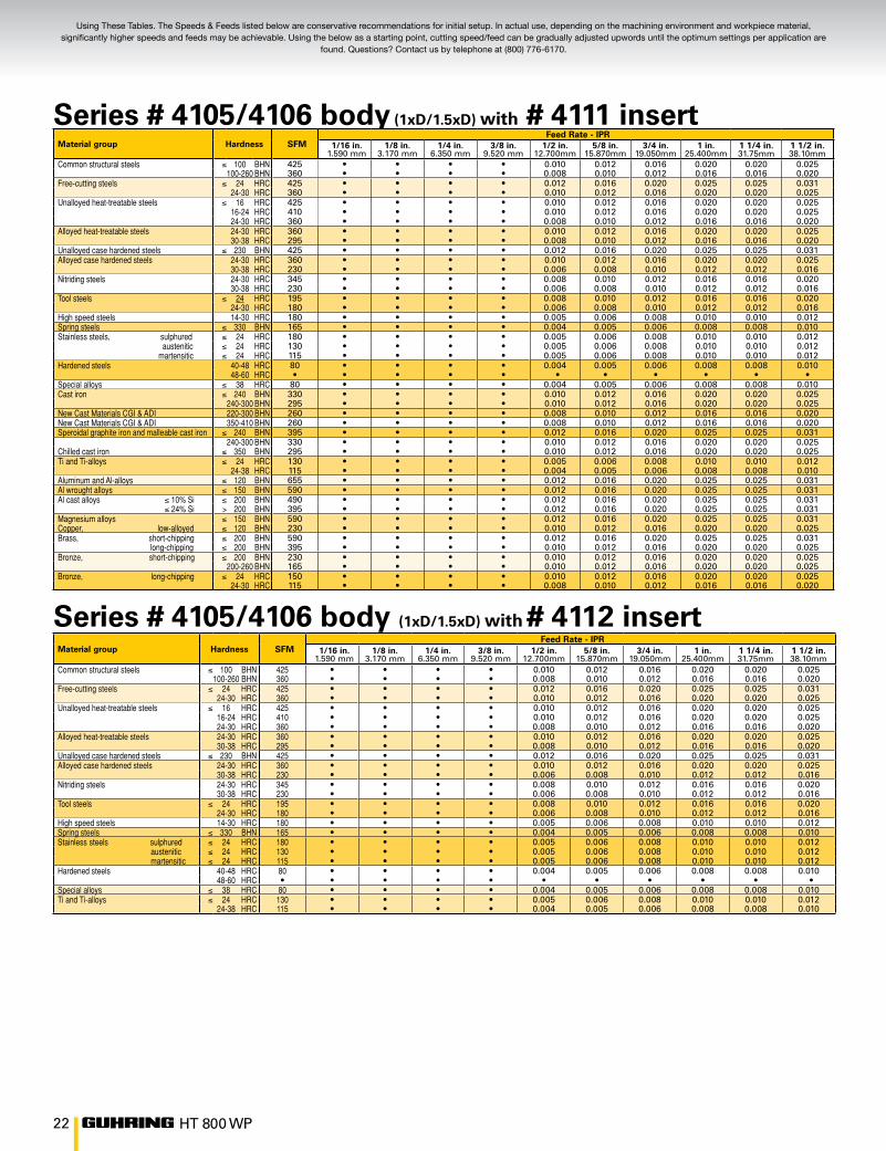
Series # 4105/4106 body (1xD/1.5xD) with # 4112 insert
Series # 4105/4106 body (1xD/1.5xD) with # 4111 insert
Material group Hardness SFMFeed Rate - IPR
1/16 in.1.590 mm
1/8 in.3.170 mm
1/4 in.6.350 mm
3/8 in.9.520 mm
1/2 in.12.700mm
5/8 in.15.870mm
3/4 in.19.050mm
1 in.25.400mm
1 1/4 in. 31.75mm
1 1/2 in. 38.10mm
Common structural steels ≤ 100 BHN 425 • • • • 0.010 0.012 0.016 0.020 0.020 0.025100-260 BHN 360 • • • • 0.008 0.010 0.012 0.016 0.016 0.020
Free-cutting steels ≤ 24 HRC 425 • • • • 0.012 0.016 0.020 0.025 0.025 0.03124-30 HRC 360 • • • • 0.010 0.012 0.016 0.020 0.020 0.025
Unalloyed heat-treatable steels ≤ 16 HRC 425 • • • • 0.010 0.012 0.016 0.020 0.020 0.02516-24 HRC 410 • • • • 0.010 0.012 0.016 0.020 0.020 0.02524-30 HRC 360 • • • • 0.008 0.010 0.012 0.016 0.016 0.020
Alloyed heat-treatable steels 24-30 HRC 360 • • • • 0.010 0.012 0.016 0.020 0.020 0.02530-38 HRC 295 • • • • 0.008 0.010 0.012 0.016 0.016 0.020
Unalloyed case hardened steels ≤ 230 BHN 425 • • • • 0.012 0.016 0.020 0.025 0.025 0.031Alloyed case hardened steels 24-30 HRC 360 • • • • 0.010 0.012 0.016 0.020 0.020 0.025
30-38 HRC 230 • • • • 0.006 0.008 0.010 0.012 0.012 0.016Nitriding steels 24-30 HRC 345 • • • • 0.008 0.010 0.012 0.016 0.016 0.020
30-38 HRC 230 • • • • 0.006 0.008 0.010 0.012 0.012 0.016Tool steels ≤ 24 HRC 195 • • • • 0.008 0.010 0.012 0.016 0.016 0.020
24-30 HRC 180 • • • • 0.006 0.008 0.010 0.012 0.012 0.016High speed steels 14-30 HRC 180 • • • • 0.005 0.006 0.008 0.010 0.010 0.012Spring steels ≤ 330 BHN 165 • • • • 0.004 0.005 0.006 0.008 0.008 0.010Stainless steels sulphured ≤ 24 HRC 180 • • • • 0.005 0.006 0.008 0.010 0.010 0.012 austenitic ≤ 24 HRC 130 • • • • 0.005 0.006 0.008 0.010 0.010 0.012 martensitic ≤ 24 HRC 115 • • • • 0.005 0.006 0.008 0.010 0.010 0.012Hardened steels 40-48 HRC 80 • • • • 0.004 0.005 0.006 0.008 0.008 0.010
48-60 HRC • • • • • • • • • • ● •Special alloys ≤ 38 HRC 80 • • • • 0.004 0.005 0.006 0.008 0.008 0.010Ti and Ti-alloys ≤ 24 HRC 130 • • • • 0.005 0.006 0.008 0.010 0.010 0.012
24-38 HRC 115 • • • • 0.004 0.005 0.006 0.008 0.008 0.010
Material group Hardness SFMFeed Rate - IPR
1/16 in.1.590 mm
1/8 in.3.170 mm
1/4 in.6.350 mm
3/8 in.9.520 mm
1/2 in.12.700mm
5/8 in.15.870mm
3/4 in.19.050mm
1 in.25.400mm
1 1/4 in. 31.75mm
1 1/2 in. 38.10mm
Common structural steels ≤ 100 BHN 425 • • • • 0.010 0.012 0.016 0.020 0.020 0.025100-260 BHN 360 • • • • 0.008 0.010 0.012 0.016 0.016 0.020
Free-cutting steels ≤ 24 HRC 425 • • • • 0.012 0.016 0.020 0.025 0.025 0.03124-30 HRC 360 • • • • 0.010 0.012 0.016 0.020 0.020 0.025
Unalloyed heat-treatable steels ≤ 16 HRC 425 • • • • 0.010 0.012 0.016 0.020 0.020 0.02516-24 HRC 410 • • • • 0.010 0.012 0.016 0.020 0.020 0.02524-30 HRC 360 • • • • 0.008 0.010 0.012 0.016 0.016 0.020
Alloyed heat-treatable steels 24-30 HRC 360 • • • • 0.010 0.012 0.016 0.020 0.020 0.02530-38 HRC 295 • • • • 0.008 0.010 0.012 0.016 0.016 0.020
Unalloyed case hardened steels ≤ 230 BHN 425 • • • • 0.012 0.016 0.020 0.025 0.025 0.031Alloyed case hardened steels 24-30 HRC 360 • • • • 0.010 0.012 0.016 0.020 0.020 0.025
30-38 HRC 230 • • • • 0.006 0.008 0.010 0.012 0.012 0.016Nitriding steels 24-30 HRC 345 • • • • 0.008 0.010 0.012 0.016 0.016 0.020
30-38 HRC 230 • • • • 0.006 0.008 0.010 0.012 0.012 0.016Tool steels ≤ 24 HRC 195 • • • • 0.008 0.010 0.012 0.016 0.016 0.020
24-30 HRC 180 • • • • 0.006 0.008 0.010 0.012 0.012 0.016High speed steels 14-30 HRC 180 • • • • 0.005 0.006 0.008 0.010 0.010 0.012Spring steels ≤ 330 BHN 165 • • • • 0.004 0.005 0.006 0.008 0.008 0.010Stainless steels, sulphured ≤ 24 HRC 180 • • • • 0.005 0.006 0.008 0.010 0.010 0.012 austenitic ≤ 24 HRC 130 • • • • 0.005 0.006 0.008 0.010 0.010 0.012 martensitic ≤ 24 HRC 115 • • • • 0.005 0.006 0.008 0.010 0.010 0.012Hardened steels 40-48 HRC 80 • • • • 0.004 0.005 0.006 0.008 0.008 0.010
48-60 HRC • • • • • ● • • • • • •Special alloys ≤ 38 HRC 80 • • • • 0.004 0.005 0.006 0.008 0.008 0.010Cast iron ≤ 240 BHN 330 • • • • 0.010 0.012 0.016 0.020 0.020 0.025
240-300 BHN 295 • • • • 0.010 0.012 0.016 0.020 0.020 0.025New Cast Materials CGI & ADI 220-300 BHN 260 • • • • 0.008 0.010 0.012 0.016 0.016 0.020New Cast Materials CGI & ADI 350-410 BHN 260 • • • • 0.008 0.010 0.012 0.016 0.016 0.020Speroidal graphite iron and malleable cast iron ≤ 240 BHN 395 • • • • 0.012 0.016 0.020 0.025 0.025 0.031
240-300 BHN 330 • • • • 0.010 0.012 0.016 0.020 0.020 0.025Chilled cast iron ≤ 350 BHN 295 • • • • 0.010 0.012 0.016 0.020 0.020 0.025Ti and Ti-alloys ≤ 24 HRC 130 • • • • 0.005 0.006 0.008 0.010 0.010 0.012
24-38 HRC 115 • • • • 0.004 0.005 0.006 0.008 0.008 0.010Aluminum and Al-alloys ≤ 120 BHN 655 • • • • 0.012 0.016 0.020 0.025 0.025 0.031Al wrought alloys ≤ 150 BHN 590 • • • • 0.012 0.016 0.020 0.025 0.025 0.031Al cast alloys ≤ 10% Si ≤ 200 BHN 490 • • • • 0.012 0.016 0.020 0.025 0.025 0.031 ≤ 24% Si > 200 BHN 395 • • • • 0.012 0.016 0.020 0.025 0.025 0.031Magnesium alloys ≤ 150 BHN 590 • • • • 0.012 0.016 0.020 0.025 0.025 0.031Copper, low-alloyed ≤ 120 BHN 230 • • • • 0.010 0.012 0.016 0.020 0.020 0.025Brass, short-chipping ≤ 200 BHN 590 • • • • 0.012 0.016 0.020 0.025 0.025 0.031 long-chipping ≤ 200 BHN 395 • • • • 0.010 0.012 0.016 0.020 0.020 0.025Bronze, short-chipping ≤ 200 BHN 230 • • • • 0.010 0.012 0.016 0.020 0.020 0.025
200-260 BHN 165 • • • • 0.010 0.012 0.016 0.020 0.020 0.025Bronze, long-chipping ≤ 24 HRC 150 • • • • 0.010 0.012 0.016 0.020 0.020 0.025
24-30 HRC 115 • • • • 0.008 0.010 0.012 0.016 0.016 0.020
Using These Tables. The Speeds & Feeds listed below are conservative recommendations for initial setup. In actual use, depending on the machining environment and workpiece material, significantly higher speeds and feeds may be achievable. Using the below as a starting point, cutting speed/feed can be gradually adjusted upwords until the optimum settings per application are
found. Questions? Contact us by telephone at (800) 776-6170.

23HT 800 WP
Using These Tables. The Speeds & Feeds listed below are conservative recommendations for initial setup. In actual use, depending on the machining environment and workpiece material, significantly higher speeds and feeds may be achievable. Using the below as a starting point, cutting speed/feed can be gradually adjusted upwords until the optimum settings per application are
found. Questions? Contact us by telephone at (800) 776-6170.
Series # 4105/4106 body (1xD/1.5xD) with # 4115 insert
Series # 4105/4106 body (1xD/1.5xD) with # 4113 insert
Series # 4105/4106 body (1xD/1.5xD) with #4114 insert
Material group Hardness SFMFeed Rate - IPR
1/16 in. 1/8 in. 1/4 in. 3/8 in. 1/2 in. 5/8 in. 3/4 in. 1 in. 1 1/4 in. 1 1/2 in.
Cast iron <240 Bhn 330240-300 Bhn
New Cast Materials CGI & ADI 220-300 Bhn 260New Cast Materials CGI & ADI 350-410 Bhn 260Speroidal graphite iron and malleable cast iron <240 Bhn
240-300 Bhn 330
Material group Hardness SFMFeed Rate - IPR
1/16 in. 1/8 in. 1/4 in. 3/8 in. 1/2 in. 5/8 in. 3/4 in. 1 in. 1 1/4 in. 1 1/2 in.
Aluminium and Al-alloys <120 BhnAl wrought alloys <150 Bhn 590Al cast alloys < 10% Si <200 Bhn 490 < 24% Si <200 Bhn 395Magnesium alloys <150 Bhn 590Copper, low-alloyed <120 Bhn 230Brass, short-chipping <200 Bhn 590 long-chipping 200-260 Bhn 395Bronze, long-chipping <24 Bhn 230
24-30 Bhn 165
Material group Hardness SFMFeed Rate - IPR
1/16 in. 1/8 in. 1/4 in. 3/8 in. 1/2 in. 5/8 in. 3/4 in. 1 in. 1 1/4 in. 1 1/2 in.
Stainless steels, sulphured <24 Rc 180 austenitic <24 Rc 130 martensitic <24 Rc 115Hardened steels 40-48 80
48-60Special alloys 38 80Chilled cast iron <350 Bhn 295Ti and Ti-alloys <24 Rc 130
>24-38 Rc 115
24 HT 800 WP
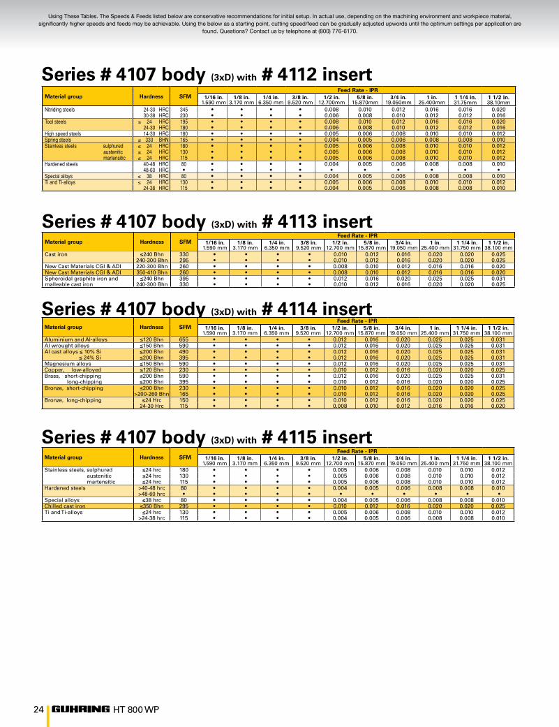
Using These Tables. The Speeds & Feeds listed below are conservative recommendations for initial setup. In actual use, depending on the machining environment and workpiece material, significantly higher speeds and feeds may be achievable. Using the below as a starting point, cutting speed/feed can be gradually adjusted upwords until the optimum settings per application are
found. Questions? Contact us by telephone at (800) 776-6170.
Series # 4107 body (3xD) with # 4112 insert
Series # 4107 body (3xD) with # 4113 insert Material group Hardness SFM
Feed Rate - IPR1/16 in.
1.590 mm1/8 in.
3.170 mm1/4 in.
6.350 mm3/8 in.
9.520 mm1/2 in.
12.700 mm5/8 in.
15.870 mm3/4 in.
19.050 mm1 in.
25.400 mm1 1/4 in.
31.750 mm1 1/2 in.
38.100 mmCast iron ≤240 Bhn 330 • • • • 0.010 0.012 0.016 0.020 0.020 0.025
240-300 Bhn 295 • • • • 0.010 0.012 0.016 0.020 0.020 0.025New Cast Materials CGI & ADI 220-300 Bhn 260 • • • • 0.008 0.010 0.012 0.016 0.016 0.020New Cast Materials CGI & ADI 350-410 Bhn 260 • • • • 0.008 0.010 0.012 0.016 0.016 0.020Spheroidal graphite iron and ≤240 Bhn 395 • • • • 0.012 0.016 0.020 0.025 0.025 0.031malleable cast iron 240-300 Bhn 330 • • • • 0.010 0.012 0.016 0.020 0.020 0.025
Series # 4107 body (3xD) with # 4114 insert
Series # 4107 body (3xD) with # 4115 insert
Material group Hardness SFMFeed Rate - IPR
1/16 in.1.590 mm
1/8 in.3.170 mm
1/4 in.6.350 mm
3/8 in.9.520 mm
1/2 in.12.700 mm
5/8 in.15.870 mm
3/4 in.19.050 mm
1 in.25.400 mm
1 1/4 in.31.750 mm
1 1/2 in.38.100 mm
Aluminium and Al-alloys ≤120 Bhn 655 • • • • 0.012 0.016 0.020 0.025 0.025 0.031Al wrought alloys ≤150 Bhn 590 • • • • 0.012 0.016 0.020 0.025 0.025 0.031Al cast alloys ≤ 10% Si ≤200 Bhn 490 • • • • 0.012 0.016 0.020 0.025 0.025 0.031 ≤ 24% Si ≤200 Bhn 395 • • • • 0.012 0.016 0.020 0.025 0.025 0.031Magnesium alloys ≤150 Bhn 590 • • • • 0.012 0.016 0.020 0.025 0.025 0.031Copper, low-alloyed ≤120 Bhn 230 • • • • 0.010 0.012 0.016 0.020 0.020 0.025Brass, short-chipping ≤200 Bhn 590 • • • • 0.012 0.016 0.020 0.025 0.025 0.031 long-chipping ≤200 Bhn 395 • • • • 0.010 0.012 0.016 0.020 0.020 0.025Bronze, short-chipping ≤200 Bhn 230 • • • • 0.010 0.012 0.016 0.020 0.020 0.025
>200-260 Bhn 165 • • • • 0.010 0.012 0.016 0.020 0.020 0.025Bronze, long-chipping ≤24 Hrc 150 • • • • 0.010 0.012 0.016 0.020 0.020 0.025
24-30 Hrc 115 • • • • 0.008 0.010 0.012 0.016 0.016 0.020
Material group Hardness SFMFeed Rate - IPR
1/16 in.1.590 mm
1/8 in.3.170 mm
1/4 in.6.350 mm
3/8 in.9.520 mm
1/2 in.12.700 mm
5/8 in.15.870 mm
3/4 in.19.050 mm
1 in.25.400 mm
1 1/4 in.31.750 mm
1 1/2 in.38.100 mm
Stainless steels, sulphured ≤24 hrc 180 • • • • 0.005 0.006 0.008 0.010 0.010 0.012 austenitic ≤24 hrc 130 • • • • 0.005 0.006 0.008 0.010 0.010 0.012 martensitic ≤24 hrc 115 • • • • 0.005 0.006 0.008 0.010 0.010 0.012Hardened steels >40-48 hrc 80 • • • • 0.004 0.005 0.006 0.008 0.008 0.010
>48-60 hrc • • • • • • • • • • •Special alloys ≤38 hrc 80 • • • • 0.004 0.005 0.006 0.008 0.008 0.010Chilled cast iron ≤350 Bhn 295 • • • • 0.010 0.012 0.016 0.020 0.020 0.025Ti and Ti-alloys ≤24 hrc 130 • • • • 0.005 0.006 0.008 0.010 0.010 0.012
>24-38 hrc 115 • • • • 0.004 0.005 0.006 0.008 0.008 0.010
Material group Hardness SFMFeed Rate - IPR
1/16 in.1.590 mm
1/8 in.3.170 mm
1/4 in.6.350 mm
3/8 in.9.520 mm
1/2 in.12.700mm
5/8 in.15.870mm
3/4 in.19.050mm
1 in.25.400mm
1 1/4 in. 31.75mm
1 1/2 in. 38.10mm
Nitriding steels 24-30 HRC 345 • • • • 0.008 0.010 0.012 0.016 0.016 0.02030-38 HRC 230 • • • • 0.006 0.008 0.010 0.012 0.012 0.016
Tool steels ≤ 24 HRC 195 • • • • 0.008 0.010 0.012 0.016 0.016 0.02024-30 HRC 180 • • • • 0.006 0.008 0.010 0.012 0.012 0.016
High speed steels 14-30 HRC 180 • • • • 0.005 0.006 0.008 0.010 0.010 0.012Spring steels ≤ 330 BHN 165 • • • • 0.004 0.005 0.006 0.008 0.008 0.010Stainless steels sulphured ≤ 24 HRC 180 • • • • 0.005 0.006 0.008 0.010 0.010 0.012 austenitic ≤ 24 HRC 130 • • • • 0.005 0.006 0.008 0.010 0.010 0.012 martensitic ≤ 24 HRC 115 • • • • 0.005 0.006 0.008 0.010 0.010 0.012Hardened steels 40-48 HRC 80 • • • • 0.004 0.005 0.006 0.008 0.008 0.010
48-60 HRC • • • • • • • • • • •Special alloys ≤ 38 HRC 80 • • • • 0.004 0.005 0.006 0.008 0.008 0.010Ti and Ti-alloys ≤ 24 HRC 130 • • • • 0.005 0.006 0.008 0.010 0.010 0.012
24-38 HRC 115 • • • • 0.004 0.005 0.006 0.008 0.008 0.010

25HT 800 WP
m/min. = SFM ÷ 3.28 Bar = PSI ÷ 14.50mm/rev. = IPR x 25.40 Liter = Gal. ÷ 3.79
RPM = SFM x 3.82 IPM = IPR x RPM DIAM. in.
HOLE DEPTH in. x 60 = Cut Time mm = in. x 25.40 IPM
Series # 4108 body (5xD) with # 4112 insert
Material group Hardness SFMFeed Rate - IPR
1/16 in.1.590 mm
1/8 in.3.170 mm
1/4 in.6.350 mm
3/8 in.9.520 mm
1/2 in.12.700 mm
5/8 in.15.870 mm
3/4 in.19.050 mm
1 in.25.400 mm
1 1/4 in.31.750 mm
1 1/2 in.38.100 mm
Stainless steels, sulphured ≤24 Rc 180 • • • • 0.005 0.006 0.008 0.010 0.010 0.012 austenitic ≤24 Rc 130 • • • • 0.005 0.006 0.008 0.010 0.010 0.012 martensitic ≤24 Rc 115 • • • • 0.005 0.006 0.008 0.010 0.010 0.012Hardened steels 40-48 Rc 80 • • • • 0.004 0.005 0.006 0.008 0.008 0.010
48-60 Rc •● • • • • • • • • • •Special alloys ≤38 Rc 80 • • • • 0.004 0.005 0.006 0.008 0.008 0.010Chilled cast iron ≤350 Bhn 295 • • • • 0.010 0.012 0.016 0.020 0.020 0.025Ti and Ti-alloys ≤24 Rc 130 • • • • 0.005 0.006 0.008 0.010 0.010 0.012
>24-38 Rc 115 • • • • 0.004 0.005 0.006 0.008 0.008 0.010
Series # 4108 body (5xD) with # 4113 insertMaterial group Hardness SFM
Feed Rate - IPR1/16 in.
1.590 mm1/8 in.
3.170 mm1/4 in.
6.350 mm3/8 in.
9.520 mm1/2 in.
12.700 mm5/8 in.
15.870 mm3/4 in.
19.050 mm1 in.
25.400 mm1 1/4 in.
31.750 mm1 1/2 in.
38.100 mmCast iron ≤240 Bhn 330 • • • • 0.010 0.012 0.016 0.020 0.020 0.025
240-300 Bhn 295 • • • • 0.010 0.012 0.016 0.020 0.020 0.025New Cast Materials CGI & ADI 220-300 Bhn 260 • • • • 0.008 0.010 0.012 0.016 0.016 0.020New Cast Materials CGI & ADI 350-410 Bhn 260 • • • • 0.008 0.010 0.012 0.016 0.016 0.020Spheroidal graphite iron and ≤240 Bhn 395 • • • • 0.012 0.016 0.020 0.025 0.025 0.031malleable cast iron 240-300 Bhn 330 • • • • 0.010 0.012 0.016 0.020 0.020 0.025
Series # 4108 body (5xD) with # 4114 insert
Series # 4108 body (5xD) with # 4115 insert
Material group Hardness SFMFeed Rate - IPR
1/16 in.1.590 mm
1/8 in.3.170 mm
1/4 in.6.350 mm
3/8 in.9.520 mm
1/2 in.12.700 mm
5/8 in.15.870 mm
3/4 in.19.050 mm
1 in.25.400 mm
1 1/4 in.31.750 mm
1 1/2 in.38.100 mm
Aluminium and Al-alloys ≤120 Bhn 655 • • • • 0.012 0.016 0.020 0.025 0.025 0.031Al wrought alloys ≤150 Bhn 590 • • • • 0.012 0.016 0.020 0.025 0.025 0.031Al cast alloys ≤ 10% Si ≤200 Bhn 490 • • • • 0.012 0.016 0.020 0.025 0.025 0.031 ≤ 24% Si ≤200 Bhn 395 • • • • 0.012 0.016 0.020 0.025 0.025 0.031Magnesium alloys ≤150 Bhn 590 • • • • 0.012 0.016 0.020 0.025 0.025 0.031Copper, low-alloyed ≤120 Bhn 230 • • • • 0.010 0.012 0.016 0.020 0.020 0.025Brass, short-chipping ≤200 Bhn 590 • • • • 0.012 0.016 0.020 0.025 0.025 0.031 long-chipping ≤200 Bhn 395 • • • • 0.010 0.012 0.016 0.020 0.020 0.025Bronze, short-chipping ≤200 Bhn 230 • • • • 0.010 0.012 0.016 0.020 0.020 0.025
>200-260 Bhn 165 • • • • 0.010 0.012 0.016 0.020 0.020 0.025Bronze, long-chipping ≤24 Rc 150 • • • • 0.010 0.012 0.016 0.020 0.020 0.025
24-30 Rc 115 • • • • 0.008 0.010 0.012 0.016 0.016 0.020
Material group Hardness SFMFeed Rate - IPR
1/16 in.1.590 mm
1/8 in.3.170 mm
1/4 in.6.350 mm
3/8 in.9.520 mm
1/2 in.12.700mm
5/8 in.15.870mm
3/4 in.19.050mm
1 in.25.400mm
1 1/4 in. 31.75mm
1 1/2 in. 38.10mm
Common structural steels ≤ 100 BHN 425 • • • • 0.010 0.012 0.016 0.020 0.020 0.025100-260 BHN 360 • • • • 0.008 0.010 0.012 0.016 0.016 0.020
Free-cutting steels ≤ 24 HRC 425 • • • • 0.012 0.016 0.020 0.025 0.025 0.03124-30 HRC 360 • • • • 0.010 0.012 0.016 0.020 0.020 0.025
Unalloyed heat-treatable steels ≤ 16 HRC 425 • • • • 0.010 0.012 0.016 0.020 0.020 0.02516-24 HRC 410 • • • • 0.010 0.012 0.016 0.020 0.020 0.02524-30 HRC 360 • • • • 0.008 0.010 0.012 0.016 0.016 0.020
Alloyed heat-treatable steels 24-30 HRC 360 • • • • 0.010 0.012 0.016 0.020 0.020 0.02530-38 HRC 295 • • • • 0.008 0.010 0.012 0.016 0.016 0.020
Unalloyed case hardened steels ≤ 230 BHN 425 • • • • 0.012 0.016 0.020 0.025 0.025 0.031Alloyed case hardened steels 24-30 HRC 360 • • • • 0.010 0.012 0.016 0.020 0.020 0.025
30-38 HRC 230 • • • • 0.006 0.008 0.010 0.012 0.012 0.016Nitriding steels 24-30 HRC 345 • • • • 0.008 0.010 0.012 0.016 0.016 0.020
30-38 HRC 230 • • • • 0.006 0.008 0.010 0.012 0.012 0.016Tool steels ≤ 24 HRC 195 • • • • 0.008 0.010 0.012 0.016 0.016 0.020
24-30 HRC 180 • • • • 0.006 0.008 0.010 0.012 0.012 0.016High speed steels 14-30 HRC 180 • • • • 0.005 0.006 0.008 0.010 0.010 0.012Spring steels ≤ 330 BHN 165 • • • • 0.004 0.005 0.006 0.008 0.008 0.010Stainless steels sulphured ≤ 24 HRC 180 • • • • 0.005 0.006 0.008 0.010 0.010 0.012 austenitic ≤ 24 HRC 130 • • • • 0.005 0.006 0.008 0.010 0.010 0.012 martensitic ≤ 24 HRC 115 • • • • 0.005 0.006 0.008 0.010 0.010 0.012Hardened steels 40-48 HRC 80 • • • • 0.004 0.005 0.006 0.008 0.008 0.010
48-60 HRC • • • • • • • • • • •Special alloys ≤ 38 HRC 80 • • • • 0.004 0.005 0.006 0.008 0.008 0.010Ti and Ti-alloys ≤ 24 HRC 130 • • • • 0.005 0.006 0.008 0.010 0.010 0.012
24-38 HRC 115 • • • • 0.004 0.005 0.006 0.008 0.008 0.010

26 HT 800 WP
Using These Tables. The Speeds & Feeds listed below are conservative recommendations for initial setup. In actual use, depending on the machining environment and workpiece material, significantly higher speeds and feeds may be achievable. Using the below as a starting point, cutting speed/feed can be gradually adjusted upwords until the optimum settings per application are
found. Questions? Contact us by telephone at (800) 776-6170.
Series # 4109 body (7xD) with # 4112 insert
Series # 4109 body (7xD) with # 4113 insert
Series # 4109 body (7xD) with # 4114 insert
Series # 4109 body (7xD) with # 4115 insert
Material group Hardness SFMFeed Rate - IPR
1/16 in.1.590 mm
1/8 in.3.170 mm
1/4 in.6.350 mm
3/8 in.9.520 mm
1/2 in.12.700 mm
5/8 in.15.870 mm
3/4 in.19.050 mm
1 in.25.400 mm
1 1/4 in.31.750 mm
1 1/2 in.38.100 mm
Cast iron ≤240 Bhn 330 • • • • 0.010 0.012 0.016 0.020 0.020 0.025240-300 Bhn 295 • • • • 0.010 0.012 0.016 0.020 0.020 0.025
New Cast Materials CGI & ADI 240-300 Bhn 260 • • • • 0.008 0.010 0.012 0.016 0.016 0.020New Cast Materials CGI & ADI 350-410 Bhn 260 • • • • 0.008 0.010 0.012 0.016 0.016 0.020Spheroidal graphite iron and ≤240 Bhn 395 • • • • 0.012 0.016 0.020 0.025 0.025 0.031malleable cast iron 240-300 Bhn 330 • • • • 0.010 0.012 0.016 0.020 0.020 0.025
Material group Hardness SFMFeed Rate - IPR
1/16 in.1.590 mm
1/8 in.3.170 mm
1/4 in.6.350 mm
3/8 in.9.520 mm
1/2 in.12.700 mm
5/8 in.15.870 mm
3/4 in.19.050 mm
1 in.25.400 mm
1 1/4 in.31.750 mm
1 1/2 in.38.100 mm
Stainless steels, sulphured ≤24 Hrc 180 • • • • 0.004 0.005 0.006 0.008 0.008 0.010 austenitic ≤24 Hrc 130 • • • • 0.004 0.005 0.006 0.008 0.008 0.010 martensitic ≤24 Hrc 115 • • • • 0.004 0.005 0.006 0.008 0.008 0.010Hardened steels 40-48 Hrc 80 • • • • 0.003 0.004 0.005 0.006 0.006 0.008
48-60 Hrc • • • • • • • • • • ● ● •Special alloys ≤38 Hrc 80 • • • • 0.003 0.004 0.005 0.006 0.006 0.008Chilled cast iron ≤350 Bhn 295 • • • • 0.010 0.012 0.016 0.020 0.020 0.025Ti and Ti-alloys ≤24 Hrc 130 • • • • 0.004 0.005 0.006 0.008 0.008 0.010
24-38 Hrc 115 • • • • 0.003 0.004 0.005 0.006 0.006 0.008
Material group Hardness SFMFeed Rate - IPR
1/16 in.1.590 mm
1/8 in.3.170 mm
1/4 in.6.350 mm
3/8 in.9.520 mm
1/2 in.12.700 mm
5/8 in.15.870 mm
3/4 in.19.050 mm
1 in.25.400 mm
1 1/4 in.31.750 mm
1 1/2 in.38.100 mm
Aluminium and Al-alloys ≤120 Bhn 655 • • • • 0.010 0.012 0.016 0.020 0.020 0.025Al wrought alloys ≤150 Bhn 590 • • • • 0.010 0.012 0.016 0.020 0.020 0.025Al cast alloys ≤ 10% Si ≤200 Bhn 490 • • • • 0.010 0.012 0.016 0.020 0.020 0.025 ≤ 24% Si ≤200 Bhn 395 • • • • 0.010 0.012 0.016 0.020 0.020 0.025Magnesium alloys ≤150 Bhn 590 • • • • 0.010 0.012 0.016 0.020 0.020 0.025Copper, low-alloyed ≤120 Bhn 230 • • • • 0.008 0.010 0.012 0.016 0.016 0.020Brass, short-chipping ≤200 Bhn 590 • • • • 0.010 0.012 0.016 0.020 0.020 0.025 long-chipping ≤200 Bhn 395 • • • • 0.008 0.010 0.012 0.016 0.016 0.020Bronze, short-chipping ≤200 Bhn 230 • • • • 0.008 0.010 0.012 0.016 0.016 0.020
200-260 Bhn 165 • • • • 0.008 0.010 0.012 0.016 0.016 0.020Bronze, long-chipping 24 Hrc 150 • • • • 0.008 0.010 0.012 0.016 0.016 0.020
24-30 Hrc 115 • • • • 0.006 0.008 0.010 0.012 0.012 0.016
Material group Hardness SFMFeed Rate - IPR
1/16 in.1.590 mm
1/8 in.3.170 mm
1/4 in.6.350 mm
3/8 in.9.520 mm
1/2 in.12.700mm
5/8 in.15.870mm
3/4 in.19.050mm
1 in.25.400mm
1 1/4 in. 31.75mm
1 1/2 in. 38.10mm
Nitriding steels 24-30 HRC 345 • • • • 0.160 0.200 0.250 0.315 0.315 0.40030-38 HRC 230 • • • • 0.125 0.160 0.200 0.250 0.250 0.315
Tool steels ≤ 24 HRC 195 • • • • 0.160 0.200 0.250 0.315 0.315 0.40024-30 HRC 180 • • • • 0.125 0.160 0.200 0.250 0.250 0.315
High speed steels 14-30 HRC 180 • • • • 0.100 0.125 0.160 0.200 0.200 0.250Spring steels ≤ 330 BHN 165 • • • • 0.100 0.125 0.160 0.200 0.200 0.250Stainless steels sulphured ≤ 24 HRC 180 • • • • 0.100 0.125 0.160 0.200 0.200 0.250 austenitic ≤ 24 HRC 130 • • • • 0.100 0.125 0.160 0.200 0.200 0.250 martensitic ≤ 24 HRC 115 • • • • 0.100 0.125 0.160 0.200 0.200 0.250Hardened steels 40-48 HRC 80 • • • • 0.080 0.100 0.125 0.160 0.160 0.200
48-60 HRC • • • • • • • • • • •Special alloys ≤ 38 HRC 80 • • • • 0.080 0.100 0.125 0.160 0.160 0.200Ti and Ti-alloys ≤ 24 HRC 130 • • • • 0.100 0.125 0.160 0.200 0.200 0.250
24-38 HRC 115 • • • • 0.080 0.100 0.125 0.160 0.160 0.200

27HT 800 WP
m/min. = SFM ÷ 3.28 Bar = PSI ÷ 14.50mm/rev. = IPR x 25.40 Liter = Gal. ÷ 3.79
RPM = SFM x 3.82 IPM = IPR x RPM DIAM. in.
HOLE DEPTH in. x 60 = Cut Time mm = in. x 25.40 IPM
Series # 4110 body (10xD) with # 4112 insert
Material group Hardness SFMFeed Rate - IPR
1/16 in.1.590 mm
1/8 in.3.170 mm
1/4 in.6.350 mm
3/8 in.9.520 mm
1/2 in.12.700 mm
5/8 in.15.870 mm
3/4 in.19.050 mm
1 in.25.400 mm
1 1/4 in.31.750 mm
1 1/2 in.38.100 mm
Stainless steels, sulphured ≤24 Hrc 180 • • • • 0.004 0.005 0.006 0.008 0.008 0.010 austenitic ≤24 Hrc 130 • • • • 0.004 0.005 0.006 0.008 0.008 0.010 martensitic ≤24 Hrc 115 • • • • 0.004 0.005 0.006 0.008 0.008 0.010Hardened steels 40-48 Hrc 80 • • • • 0.003 0.004 0.005 0.006 0.006 0.008
48-60 Hrc • • • • • • ● • ● • ● • ● • ● • ●Special alloys ≤38 Hrc 80 • • • • 0.003 0.004 0.005 0.006 0.006 0.008Chilled cast iron ≤350 Bhn 295 • • • • 0.010 0.012 0.016 0.020 0.020 0.025Ti and Ti-alloys ≤24 Rc 130 • • • • 0.004 0.005 0.006 0.008 0.008 0.010
24-38 Rc 115 • • • • 0.003 0.004 0.005 0.006 0.006 0.008
Series # 4110 body (10xD) with # 4113 insertMaterial group Hardness SFM
Feed Rate - IPR1/16 in.
1.590 mm1/8 in.
3.170 mm1/4 in.
6.350 mm3/8 in.
9.520 mm1/2 in.
12.700 mm5/8 in.
15.870 mm3/4 in.
19.050 mm1 in.
25.400 mm1 1/4 in.
31.750 mm1 1/2 in.
38.100 mmCast iron ≤240 Bhn 330 • • • • 0.010 0.012 0.016 0.020 0.020 0.025
240-300 Bhn 295 • • • • 0.010 0.012 0.016 0.020 0.020 0.025New Cast Materials CGI & ADI 220-300 Bhn 260 • • • • 0.008 0.010 0.012 0.016 0.016 0.020New Cast Materials CGI & ADI 350-410 Bhn 260 • • • • 0.008 0.010 0.012 0.016 0.016 0.020Spheroidal graphite iron and ≤240 Bhn 395 • • • • 0.012 0.016 0.020 0.025 0.025 0.031malleable cast iron 240-300 Bhn 330 • • • • 0.010 0.012 0.016 0.020 0.020 0.025
Series # 4110 body (10xD) with # 4114 insert
Series # 4110 body (10xD) with # 4115 insert
Material group Hardness SFMFeed Rate - IPR
1/16 in.1.590 mm
1/8 in.3.170 mm
1/4 in.6.350 mm
3/8 in.9.520 mm
1/2 in.12.700 mm
5/8 in.15.870 mm
3/4 in.19.050 mm
1 in.25.400 mm
1 1/4 in.31.750 mm
1 1/2 in.38.100 mm
Aluminium and Al-alloys ≤120 Bhn 655 • • • • 0.010 0.012 0.016 0.020 0.020 0.025Al wrought alloys ≤150 Bhn 590 • • • • 0.010 0.012 0.016 0.020 0.020 0.025Al cast alloys ≤ 10% Si ≤200 Bhn 490 • • • • 0.010 0.012 0.016 0.020 0.020 0.025 ≤ 24% Si >200 Bhn 395 • • • • 0.010 0.012 0.016 0.020 0.020 0.025Magnesium alloys ≤150 Bhn 590 • • • • 0.010 0.012 0.016 0.020 0.020 0.025Copper, low-alloyed ≤120 Bhn 230 • • • • 0.008 0.010 0.012 0.016 0.016 0.020Brass, short-chipping ≤200 Bhn 590 • • • • 0.010 0.012 0.016 0.020 0.020 0.025 long-chipping ≤200 Bhn 395 • • • • 0.008 0.010 0.012 0.016 0.016 0.020Bronze, short-chipping ≤200 Bhn 230 • • • • 0.008 0.010 0.012 0.016 0.016 0.020
200-260 Bhn 165 • • • • 0.008 0.010 0.012 0.016 0.016 0.020Bronze, long-chipping ≤24 Hrc 150 • • • • 0.008 0.010 0.012 0.016 0.016 0.020
24-30 Hrc 115 • • • • 0.006 0.008 0.010 0.012 0.012 0.016
Material group Hardness SFMFeed Rate - IPR
1/16 in.1.590 mm
1/8 in.3.170 mm
1/4 in.6.350 mm
3/8 in.9.520 mm
1/2 in.12.700mm
5/8 in.15.870mm
3/4 in.19.050mm
1 in.25.400mm
1 1/4 in. 31.75mm
1 1/2 in. 38.10mm
Common structural steels ≤ 100 BHN 425 • • • • 0.200 0.250 0.315 0.400 0.400 0.500100-260 BHN 360 • • • • 0.160 0.200 0.250 0.315 0.315 0.400
Free-cutting steels ≤ 24 HRC 425 • • • • 0.250 0.315 0.400 0.500 0.500 0.63024-30 HRC 360 • • • • 0.200 0.250 0.315 0.400 0.400 0.500
Unalloyed heat-treatable steels ≤ 16 HRC 425 • • • • 0.200 0.250 0.315 0.400 0.400 0.50016-24 HRC 410 • • • • 0.200 0.250 0.315 0.400 0.400 0.50024-30 HRC 360 • • • • 0.160 0.200 0.250 0.315 0.315 0.400
Alloyed heat-treatable steels 24-30 HRC 360 • • • • 0.200 0.250 0.315 0.400 0.400 0.50030-38 HRC 295 • • • • 0.160 0.200 0.250 0.315 0.315 0.400
Unalloyed case hardened steels ≤ 230 BHN 425 • • • • 0.250 0.315 0.400 0.500 0.500 0.630Alloyed case hardened steels 24-30 HRC 360 • • • • 0.200 0.250 0.315 0.400 0.400 0.500
30-38 HRC 230 • • • • 0.160 0.200 0.250 0.315 0.315 0.400Nitriding steels 24-30 HRC 345 • • • • 0.160 0.200 0.250 0.315 0.315 0.400
30-38 HRC 230 • • • • 0.125 0.160 0.200 0.250 0.250 0.315Tool steels ≤ 24 HRC 195 • • • • 0.160 0.200 0.250 0.315 0.315 0.400
24-30 HRC 180 • • • • 0.125 0.160 0.200 0.250 0.250 0.315High speed steels 14-30 HRC 180 • • • • 0.100 0.125 0.160 0.200 0.200 0.250Spring steels ≤ 330 BHN 165 • • • • 0.100 0.125 0.160 0.200 0.200 0.250Stainless steels sulphured ≤ 24 HRC 180 • • • • 0.100 0.125 0.160 0.200 0.200 0.250 austenitic ≤ 24 HRC 130 • • • • 0.100 0.125 0.160 0.200 0.200 0.250 martensitic ≤ 24 HRC 115 • • • • 0.100 0.125 0.160 0.200 0.200 0.250Hardened steels 40-48 HRC 80 • • • • 0.080 0.100 0.125 0.160 0.160 0.200
48-60 HRC • • • • • • • • • • •Special alloys ≤ 38 HRC 80 • • • • 0.080 0.100 0.125 0.160 0.160 0.200Ti and Ti-alloys ≤ 24 HRC 130 • • • • 0.100 0.125 0.160 0.200 0.200 0.250
24-38 HRC 115 • • • • 0.080 0.100 0.125 0.160 0.160 0.200

Surface Refining Processes, Coatings For HT 800 WP Interchangeable Inserts
TiAlN
TiAlN SuperA/nanoA
bright
TiCNFIREX®/nanoFIREX®
TiN

HT 800 WP Special Solutions
stepped holdersspecial clamping chucks inserts with special coatings and geometries, e.g. radius inserts or inserts with point angles 90° to 180°

30 HT 800 WP
Troubleshooting
12 tips to help diagnose problems
Cutting edge build up
Crumbling of outer corners
Heavy wear at flank
Crumbling on cutting lips
Land wear
Scoring on tool body
Problem Cause Remedy
31HT 800 WP
Ra
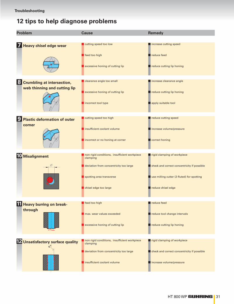
Troubleshooting
12 tips to help diagnose problems
Heavy chisel edge wear
Crumbling at intersection,web thinning and cutting lip
Plastic deformation of outer corner
Misalignment
Heavy burring on break-through
Unsatisfactory surface quality
Problem Cause Remedy

Item
# 4
0000
1028
1
1/14
Guhring, Inc. Main OfficeP.O. Box 643, Brookfield, WI 53008-0643
Shipping Address1445 Commerce AvenueBrookfield, WI 53045Tel (262) 784-6730 (800) 776-6170Fax (262) 784-9096
West Coast Distribution Center and Reconditioning Facility15581 Computer Ln Huntington Beach, CA 92649
Reconditioning Facility121 W Dudley Town Rd.Bloomfield, CT 06002
Manufacturing and Reconditioning Facility29550 W.K. Smith Rd. Suite BNew Hudson, MI 48165
Guhring Corporation20 Steckle Place, Unit #14Kitchener, ON N2E 2C3Tel (519) 748-9664 (800) 463-5555Fax (519) 748-2954
SPECIAL TOOLINGSOLUTIONS
MODULAR TOOLING SYSTEMS
COUNTERSINKING/DE-BURRING
DRILLING MILLING
TOOL RECONDITIONING SERVICE
REAMING PCD/PCBNTAPPING/THREADMILLING/FLUTELESS TAPPING