HSM1 ASM1 IPM1 - brusa.biz · and photos used are copyrighted and failure to respect this ... ASM...
85
BRUSA Elektronik AG Neudorf 14 CH-9466 Sennwald +41 81 758 19 00 [email protected] www.brusa.biz HSM1 ASM1 IPM1 TECHNICAL DATA AND START-UP Translation of the original German operating instructions
Transcript of HSM1 ASM1 IPM1 - brusa.biz · and photos used are copyrighted and failure to respect this ... ASM...

BRUSA Elektronik AG Neudorf 14 CH-9466 Sennwald +41 81 758 19 00
www.brusa.biz
HSM1
ASM1
IPM1
TECHNICAL DATA
AND START-UP
Translation of the original German operating instructions

Technical data
and Start-up
HSM1 / ASM1 / IPM1
2
LEGAL NOTICE
Publisher BRUSA Elektronik AG
Neudorf 14 CH-9466 Sennwald T +41 81 758 19–00 F +41 81 758 19–99 www.brusa.biz [email protected]
Date of issue 14. January 2014
Copyright © 2011
The content of this document may not be passed on to third parties without the written authorisation of the company BRUSA Elektronik AG - not even in extracts. Any technical information, drawings and photos used are copyrighted and failure to respect this constitutes a punishable offence!
Updates In light of the further technical development of our products, we reserve the right for structural changes. Any changes will be disclosed in the relevant manuals through the replacement of the relevant pages and/or a revision of the electronic data storage device.
Writer / Author M. Tschumper
REVISIONS
REVISION DATE NAME CHANGE
rev01 24.01.12 H. Schmidt 4.3 Delivery contents updated, 6.3.3 new, 7 profiles added to, content revised
rev02 18.01.2013 H.Schmidt 6.1 und 6.2 TD aktualisiert
rev03 18.06.2013 M.Tschumper 6.11.3 Spline data rotorshaft added, little corrections
rev04 23.07.2013 M.Tschumper 6.1 and 6.2 TD
rev05 30.09.2013 M.Tschumper 6.6 Grafik Safety measures
rev06 16.10.2013 M.Tschumper 7.1-7.3 motor characteristics / language EN
rev07 12.11.2013 M.Tschumper Merging HSM/IPM/ASM
rev08 14.01.2014 M.Tschumper Add HSM1-10.18.04
rev09 18.03.2014 M.Tschumper Add HSM1-10.18.04 efficiency table Chap: 7.4.2
rev10 04.06.2015 F. Müller chap. 8.1 add information about cable and terminal insert
rev11 13.05.2016 M. Voppichler Updated delivery contents
Added some warning instructions
Added Chap. 10 Flooding in the device
rev12 17.05.2016 M. Voppichler HSM1-10.18.22 added
rev13 22.09.2016 M. Voppichler Chap. 6.14 updated
rev14 28.11.2016 A. Girod Chap. 13 updated; Chap. 14 new
rev15 16.08.2017 R. Roth Corrections
rev16 18.10.2017 M. Cvorak Chap. 6.14 corrections

3
Technical data
and Start-up
HSM1 / ASM1 / IPM1
VALIDITY
This manual is valid only for the following motors:
MOTORTYP
HSM1-6.17.12
HSM1-10.18.13
HSM1-10.18.13-Co
ASM1-6.17.12
HSM1-6.17.12-GX
HSM1-10.18.13-GX
HSM1-10.18.04
IPM1-6.17.04
HSM1-10.18.22
Decoding of the motor designation is as follows:

Technical data
and Start-up
HSM1 / ASM1 / IPM1
4
TABLE OF CONTENTS
1 Foreword .............................................................................................................................. 8
2 List of abbreviations ........................................................................................................... 8
3 Safety and warning instructions ........................................................................................ 9
3.1 Symbols and their meaning ........................................................................................................ 9
3.2 Safety instructions and danger levels ....................................................................................... 10
3.3 Generally applicable safety measures ...................................................................................... 11
3.4 Safety installations / power limitations ...................................................................................... 14
3.4.1 Derating ............................................................................................................................ 14
3.4.2 Overload protection ........................................................................................................... 14
3.5 Requirements of the start-up personnel .................................................................................... 14
4 General ............................................................................................................................... 15
4.1 Content and scope of this manual ............................................................................................ 15
4.2 Scope of the entire documentation ........................................................................................... 15
4.3 Delivery contents ...................................................................................................................... 16
4.4 Optional delivery contents ........................................................................................................ 17
4.5 Conformity ................................................................................................................................ 18
4.6 EU Guidelines .......................................................................................................................... 18
4.7 Contact information of the manufacturer ................................................................................... 18
5 Use and limits of the product ........................................................................................... 19
5.1 Proper use of HSM1 and ASM1 ............................................................................................... 19
5.2 Proper use of IPM1 .................................................................................................................. 19
5.3 Improper use / limits of the product .......................................................................................... 20
6 About this device............................................................................................................... 21
6.1 Warnings on the motor ............................................................................................................. 21
6.2 Motor type plate ....................................................................................................................... 22
6.3 Basic principle for vehicle installation ....................................................................................... 23
6.4 Safety measures for vehicle installation .................................................................................... 24
6.4.1 Principle of operation Interlock .......................................................................................... 24
6.5 Overview of the main structural components ............................................................................ 25
6.6 Position sensor ......................................................................................................................... 25
6.7 Rotor offset............................................................................................................................... 26

5
Technical data
and Start-up
HSM1 / ASM1 / IPM1
6.8 Regulation and control system ................................................................................................. 26
6.9 Stator and temperature measurement ...................................................................................... 27
6.10 HSM1 ....................................................................................................................................... 28
6.10.1 Basic function of the HSM1 hybrid synchronous motor ...................................................... 28
6.10.2 Dimensions HSM1-xx.xx.12 / HSM1-xx.xx.13 .................................................................. 29
6.10.3 Dimensions HSM1-xx.xx.04 .............................................................................................. 29
6.10.4 Technical properties HSM1 ............................................................................................... 30
6.10.5 Technical data HSM1 ........................................................................................................ 31
6.11 ASM1 ....................................................................................................................................... 33
6.11.1 Basic function of the ASM1 asynchronous motor .............................................................. 33
6.11.2 Dimensions ASM1-xx.xx.12 ............................................................................................... 34
6.11.3 Technical properties ASM1 ............................................................................................... 34
6.11.4 Technical data ASM1 ........................................................................................................ 35
6.12 IPM1......................................................................................................................................... 37
6.12.1 Basic function of the IPM1 internal permanently excited synchronous motor ..................... 37
6.12.2 Dimensions IPM1-xx.xx.04 ................................................................................................ 38
6.12.3 Technical properties IPM1 ................................................................................................. 38
6.12.4 Technical data IPM1 .......................................................................................................... 39
6.13 Mechanical connections ........................................................................................................... 41
6.13.1 Fixing points HSM1 / ASM1 / IPM1 ................................................................................... 41
6.13.2 Cooling system .................................................................................................................. 43
6.13.3 Cooling water connections ................................................................................................ 43
6.13.4 Spline data rotorshaft ........................................................................................................ 44
6.14 Connections electrical .............................................................................................................. 45
6.14.1 Grounding screw ............................................................................................................... 45
6.14.2 Motor sensor connection PIN assignment (motor side) ..................................................... 46
7 Profiles and diagrams ....................................................................................................... 47
7.1 HSM1–6.17.12 ......................................................................................................................... 47
7.1.1 Power / torque depending on speed .................................................................................. 47
7.1.2 Level of motor efficiency .................................................................................................... 48
7.1.3 Level of generator efficiency (recuperation) ....................................................................... 49
7.1.4 S1 torque .......................................................................................................................... 50
7.1.5 Thermal behaviour / derating ............................................................................................. 51

Technical data
and Start-up
HSM1 / ASM1 / IPM1
6
7.1.6 Induced motor voltage ....................................................................................................... 54
7.1.7 Short circuit torque ............................................................................................................ 54
7.2 HSM1-10.18.13 ........................................................................................................................ 55
7.2.1 Power / torque depending on speed .................................................................................. 55
7.2.2 Level of motor efficiency .................................................................................................... 56
7.2.3 Induced motor voltage ....................................................................................................... 56
7.2.4 Short circuit torque ............................................................................................................ 57
7.3 HSM1–10.18.04 ....................................................................................................................... 58
7.3.1 Power / torque depending on speed .................................................................................. 58
7.3.2 Level of motor efficiency .................................................................................................... 59
7.3.3 Induced motor voltage ....................................................................................................... 60
7.4 HSM1-10.18.22 ........................................................................................................................ 61
7.4.1 Power / torque depending on speed .................................................................................. 61
7.4.2 Level of motor efficiency .................................................................................................... 62
7.4.3 Induced motor voltage ....................................................................................................... 63
7.5 ASM1–6.17.12 ......................................................................................................................... 64
7.5.1 Power / torque depending on speed .................................................................................. 64
7.6 IPM1–6.17.04 ........................................................................................................................... 65
7.6.1 Power / torque depending on speed .................................................................................. 65
7.6.2 Level of motor efficiency .................................................................................................... 66
7.6.3 Level of generator efficiency (recuperation) ....................................................................... 66
8 Installation / start-up ......................................................................................................... 67
8.1 Connecting the HV supply ........................................................................................................ 70
8.2 Ventilating the cooling system .................................................................................................. 73
8.3 Carrying out the HV test ........................................................................................................... 74
9 Error correction ................................................................................................................. 76
10 Flooding in the device ................................................................................................... 77
11 Maintenance ................................................................................................................... 78
11.1 Changing the O-ring of the connection box............................................................................... 79
11.2 Changing the terminal board .................................................................................................... 80
12 Spare parts ..................................................................................................................... 82
13 Warranty and guarantee ................................................................................................ 83
14 Instructions regarding disposal .................................................................................... 83

7
Technical data
and Start-up
HSM1 / ASM1 / IPM1
15 Index ................................................................................................................................ 84

Technical data
and Start-up
HSM1 / ASM1 / IPM1
8
1 Foreword
Dear customer!
With the BRUSA HSM1 hybrid synchronous motor, ASM1 asynchronous motor and IPM1 internal permanently
excited synchronous motor you have obtained a very capable and versatile product. As this is a component of high
performance electronics, we require specialist knowledge in the dealing with as well as the operation of the
product!
Read this manual - particularly the chapter Safety and Warning Instructions - carefully before you install the motor
or carry out any other work on it!
2 List of abbreviations
Throughout this manual, some specific technical abbreviations are used. You will find an overview as well as their
meaning in the following table:
ABBR. MEANING ABBR. NAME
ASM Asynchronous motor NTC Resistor with negative temperature coefficient
HSM Hybrid synchronous motor PDU Power Distribution Unit (HV distribution box)
GND Minus wiring System, vehicle earth Terminal 31
PTC Resistor with positive temperature coefficient
HV High Voltage, DC Link Voltage
PWM Pulse Width Modulation
LV Low voltage

9
Technical data
and Start-up
HSM1 / ASM1 / IPM1
3 Safety and warning instructions
In this chapter you will find safety instructions which apply to this device. These refer to assembly, start-up and
running operation in the vehicle. Always read and observe these instructions in order to protect people's safety and
lives and to avoid damage to the device!
3.1 Symbols and their meaning
Throughout this manual, some specific technical symbols are used. You will find an overview as well as their
meaning in the following table:
PROHIBITION SYMBOLS
SYMBOL MEANING SYMBOL MEANING
General prohibition
Warning high voltage
Touching forbidden
Switching on forbidden
WARNING SYMBOLS
SYMBOL MEANING SYMBOL MEANING
General hazard warning
Electromagnetic field warning
Potentially explosive warning
Battery hazard warning
Hot surface warning
High electrical voltage warning
High pressure warning / fluid spurting out
Fire hazard warning
MANDATORY SIGNS
SYMBOL MEANING SYMBOL MEANING
Disconnect device from voltage
Disconnect device from mains
INFORMATION SIGNS
SYMBOL MEANING SYMBOL MEANING
Important information on avoiding possible damage to property
Important information
Technical data
and Start-up
HSM1 / ASM1 / IPM1
10
3.2 Safety instructions and danger levels
DANGER
This instruction warns against serious, irreversible risks of injury and in some cases death!
Avoid these dangers by observing these instructions!
WARNING
This instruction warns against serious, irreversible risks of injury!
Avoid these dangers by observing these instructions!
CAUTION
This instruction warns against serious, irreversible risks of injury!
Avoid these dangers by observing these instructions!
INSTRUCTION
This instruction warns against possible damages to property if the following instructions and work procedures are not observed.
INFORMATION
This type of instruction discloses important information for the reader.

11
Technical data
and Start-up
HSM1 / ASM1 / IPM1
3.3 Generally applicable safety measures
The following safety measures have been developed based on the knowledge of the manufacturer. They are not
complete, they can be supplemented by local and/or country-specific safety instructions and guidelines for accident
prevention!
The system integrator and/or distributor of the device must therefore supplement the present general safety
instructions by country-specific and local guidelines.
3.3.1 Safety instructions for cooling water systems
WARNING
Spurting cooling fluid!
Skin burning hazard!
Check the tightness of the cooling water system, particularly the pipes, screw joints and pressure tanks.
Resolve recognisable leakages immediately!
3.3.2 Safety instructions for mechanical systems
DANGER
Potential explosion area!
Danger to life!
Do not store any highly flammable materials or combustible fluids in the direct surroundings of the device!
Sparks at the device connections can set these on fire and lead to explosions!
CAUTION
Hot surfaces!
Burn hazard!
The device produces high temperatures when in operation!
So always handle the device with care and caution!
Technical data
and Start-up
HSM1 / ASM1 / IPM1
12
3.3.3 Safety Instructions for handling and operation
INSTRUCTION
A high cooling water temperature reduces the life span! So take ongoing care to ensure sufficient cooling of the device!
Under no circumstances should you use cleaning agents containing solvents to clean the motor! These can damage the seals and lead to leaks in the motor!
Do not place the device in direct sunlight and in close proximity to heat sources!
Although if the device has high IP protection, you should avoid placing it in direct contact with water (rain, spurting water) if possible!
Under no circumstances should you put a low-resistance connection between the HV contacts, the housing contacts and the LV contacts! This will lead to malfunctions and furthermore to the destruction of the device!
Prevent any penetration of fluids into the device (e.g. during assembly work)! The penetration of fluids will lead to a short circuit and subsequent damage to the device!
Under no circumstances should you operate the device if liquid is leaking in anywhere. Refer immediately to the company BRUSA Elektronik AG!
During installation and the laying of cables, observe the maximum bending radii given by the manufacturer! Avoid laying the cables alongside sharp edges and mechanical components!
13
Technical data
and Start-up
HSM1 / ASM1 / IPM1
3.3.4 Safety instructions for electrical systems
DANGER
High voltage!
Danger to life!
Under no circumstances should you touch the HV wires or HV connections without ensuring that there is no voltage beforehand!
The device may only be connected by a qualified electrician!
Under no circumstances should you bypass or avoid security installations! Any malfunctions resulting from this could have life threatening consequences!
Always use an insulation monitoring unit for ongoing monitoring of the galvanic isolation between HV and LV circuits!
Before starting work with the device, the shut-down of the coupled motors must be ensured! Even when the HV supply is switched off, a turning motor can still produce voltage!
INSTRUCTION
Under no circumstances should the device be opened without authorisation! The opening of the device (housing sealed-up) leads directly to the forfeit of any guarantee and warranty rights!
INFORMATION
Adhere strictly to the following 5 safety rules when working on an HV grid:
Disconnect system from power. Switch off the ignition. Remove service / maintenance plug and/or turn off main battery switch. Remove fuse.
Ensure that the system does not reconnect. Keep ignition key safe to prevent unauthorised access. Keep service / maintenance plug safe to prevent unauthorised access and/or use lockable cover cap to ensure that the main battery switch does not reconnect.
Check that it is not live with a suitable voltage tester (note voltage range!).
Ground and short-circuit the system.
Cover or seal off adjacent live parts.
Technical data
and Start-up
HSM1 / ASM1 / IPM1
14
3.4 Safety installations / power limitations
3.4.1 Derating
This security installation is the motor's self-protection. If the motor reaches a defined temperature, this means a
decrease in power (derating) to protect the motor from damage through overheating. The power will subsequently
be reduced until the temperature falls back to the target range.
The temperature measurement takes place through an NTC in the stator winding head. Derating becomes active at
around 100°C through the variable resistance value. The inverter processes the signal from the motor and begins
to gradually reduce the phase current from this motor temperature onwards:
at temperature </= 100°C I_max
at temperature = 160°C I = 0 A
For this see chapt. 7.1.5 Thermal behaviour / derating.
3.4.2 Overload protection
If the motor reaches the defined maximum temperature of 170°C despite derating, an emergency shut-down
(overload protection) takes place to protect the motor from damage.
The temperature measurement takes place through 3 PTCs in the stator winding head (1 unit per phase). If one of
the PTCs reaches the defined maximum value, the linked up inverter recognises this and using the CAN sends the
error message E_TempMot. In this case the inverter disconnects the phase current immediately.
To resume operation, the fault in the linked inverter must be acknowledged.
3.5 Requirements of the start-up personnel
All courses of action described in this manual may only be carried out by a qualified electrician! Specialist staff are
defined as electricians who dispose of
professional training,
knowledge and experience in the field of electronics / electric mobility,
as well as knowledge of relevant requirements and dangers
which they can display in practice. Furthermore, they must be able to assess the work assigned to them
independently, detect possible dangers and establish necessary protection measures.

15
Technical data
and Start-up
HSM1 / ASM1 / IPM1
4 General
4.1 Content and scope of this manual
The present documentation gives the reader an overview of all required working steps in the installation and
operation of the device and the safety measures necessary for these.
Furthermore, you can find technical information, usage information along with a basic description of the motors and
their specific components.
The operational and safety instructions given must be adhered to in order to ensure the ongoing optimum
functioning of the motor and to meet the warranty requirements of the company BRUSA Elektronik AG.
All work sequences and illustrations are based on the HSM1–6.17.12 model and are applicable to all motors
mentioned in this handbook. In the case of model-specific deviations, corresponding instructions are available.
4.2 Scope of the entire documentation
INFORMATION
To set the motor up successfully, besides this manual you will need the appropriate motor table for this motor! The motor table is usually included in the delivery content and must be loaded onto the linked up inverter (see the technical information for the inverter).

Technical data
and Start-up
HSM1 / ASM1 / IPM1
16
4.3 Delivery contents
INFORMATION
The components stated below are contained in the delivery and are necessary for the start-up! In the case of possible missing parts, please refer to the manufacturing address given in chapter 4.7.
INFORMATION
For 70mm2 cables you can use 50mm
2 cable lugs too. The diameter of 70mm
2 cables fits without
problems into 50mm2 cable lugs and is qualified by BRUSA Elektronik AG.
NAME PIECES ILLUSTRATION
1. HSM1 hybrid synchronous motor
or
ASM1 asynchronous motor
1
2. Cable lugs for HV-cables (depending on the motor):
25mm2 M6 cable lug without insulation for HSM1-10.18.04
35mm2 M6 cable lug without insulation for HSM1-06.17.12
35mm2 M6 cable lug without insulation for ASM1-06.17.12
50mm2 M6 cable lug without insulation for HSM1-10.18.13
3
3. Cable lug for grounding (depending on the motor):
25mm2 M8 cable lug without insulation for HSM1-10.18.04
25mm2 M8 cable lug without insulation for IPM1-06.17.04
35mm2 M8 cable lug without insulation for HSM1-06.17.12
35mm2 M8 cable lug without insulation for ASM1-06.17.12
50mm2 M8 cable lug without insulation for HSM1-10.18.13
1
4. M8x10 hexagonal screw
(Ground GND)
1
5. M8 washer for grounding screw 1
6. Cable length of sensor cable: 1m
(Connection Motor / Inverter)
1
7. Quick connection cooling water connection pieces 90° Norma PS3
Cooling Water Pressure Drop around 150 mbars
2

17
Technical data
and Start-up
HSM1 / ASM1 / IPM1
4.4 Optional delivery contents
INFORMATION
These accessories can be obtained optionally from BRUSA Elektronik AG.
MEANING TYPE ILLUSTRATION
1. Special key for HV cable fitting RAAA041 ---
2. Quick connection cooling water connection pieces 0° Norma PS3
Cooling Water Pressure Drop around 140 mbars
For dimensions see chapt. 6.13.3 Cooling water connections
MHAA775
3. M18 x1.5 Cooling Water Connection Pieces
Cooling Water Pressure Drop around 105 mbars
For dimensions see chapt. 6.13.3 Cooling water connections
MAAA366
4. 14 pole Lemo connecting cable (inverter - motor) 1 m 11139
5. 14 pole Lemo connecting cable (inverter - motor) 2 m 11140
6. 14 pole Lemo connecting cable (inverter - motor) 4 m 11141
* only available for the HSM1-6.17.12
** Gear Box Delivery Contents Component

Technical data
and Start-up
HSM1 / ASM1 / IPM1
18
4.5 Conformity
4.6 EU Guidelines
This manual has been produced under application and consideration of the hybrid synchronous motor HSM1 EC
guidelines, national laws and harmonised standards (EN) valid at the time of production relevant to the product.
4.7 Contact information of the manufacturer
BRUSA Elektronik AG
Neudorf 14
9466 Sennwald
Switzerland
Phone: +41 81 758 09 - 00
Fax: +41 81 758 09 - 99
Internet: www.brusa.biz
E-mail: [email protected]

19
Technical data
and Start-up
HSM1 / ASM1 / IPM1
5 Use and limits of the product
5.1 Proper use of HSM1 and ASM1
The BRUSA HSM1 hybrid synchronous motor and the ASM1 asynchronous motor has been designed for the
following uses. In the case of planned operations in other areas, please contact the company BRUSA Elektronik
AG beforehand at the manufacturer address as given in chapt. 4.7.
Installation in a drive train for hybrid vehicles
Full drive for electric vehicles / Linking up with several hybrid synchronous motors possible
Installation in a drive train for fuel cell vehicles
Use as a high performance drive (racing sports)
Full drive for electric motorbikes
Full drive for utility vehicles (electric and hybrid)
Full drive for electric boats
Test stand applications
INFORMATION
This equipment is a custom built evaluation kit destined for professionals to be used solely at research and development facilities for such purposes.
5.2 Proper use of IPM1
The BRUSA internal permanently excited synchronous motor IPM1 has been designed for the applications listed
below. In the case of planned operations in other areas, please contact the company BRUSA Elektronik AG
beforehand at the manufacturer address as given in chapt. 4.7.
Primarily designed and optimized as a generator for 1 - or 2 - cylinder range extender combustion
engines
Raising and shifting the load point for combustion engines
Full drive for electric motorcycles or light vehicles
Test bench applications
INFORMATION
This equipment is a custom built evaluation kit destined for professionals to be used solely at research and development facilities for such purposes.

Technical data
and Start-up
HSM1 / ASM1 / IPM1
20
5.3 Improper use / limits of the product
The carrying out of applications which do not conform to the conditions and requirements stated in the technical
documents and datasheets of the manufacturer is viewed as improper use.
The following limit values are set for the operation of the HSM1 hybrid synchronous motor, IPM1 internal
permanently excited synchronous motor and the ASM1 asynchronous motor. Operation out of specification can
also lead to life-threatening situations!
Max HV input voltage (inverter): 450 V
Max. permitted phase voltage: 690 VACeff
Min. ambient temperature: – 40°C
Max. ambient temperature: + 85°C
Min. coolant temperature at inlet: – 40°C
Max. coolant temperature at inlet: + 65°C
Maximum cooling circuit pressure: 1.0 bar

21
Technical data
and Start-up
HSM1 / ASM1 / IPM1
6 About this device
6.1 Warnings on the motor
Warning signs are attached to the motor to warn the operator of possible dangers. Should one of these warning
signs fail or become illegible due to wear and tear, it must be immediately renewed! To get an original label, please
contact BRUSA support at the manufacturer address given in chapt. 4.7.
Technical data
and Start-up
HSM1 / ASM1 / IPM1
22
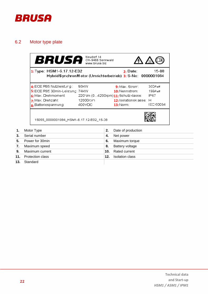
6.2 Motor type plate
1. Motor Type 2. Date of production
3. Serial number 4. Net power
5. Power for 30min 6. Maximum torque
7. Maximum speed 8. Battery voltage
9. Maximum current 10. Rated current
11. Protection class 12. Isolation class
13. Standard
1: 3:
8:
11: 10:
13: 12:
9:
7:
5:
6:
4:
2:

23
Technical data
and Start-up
HSM1 / ASM1 / IPM1
6.3 Basic principle for vehicle installation

Technical data
and Start-up
HSM1 / ASM1 / IPM1
24
6.4 Safety measures for vehicle installation
INFORMATION
This safety measure is a recommendation by the company BRUSA Elektronik AG and is understood as a basic requirement for the safe operation of electric vehicles!
6.4.1 Principle of operation Interlock
The interlock switch (1) is closed if the corresponding interlock condition of each devices is met (closed service
cover, plugged HV connections ...). The interlock evaluation of the PDU switches the 12V supply voltage (2) of the
HV contactors (4) in the battery if the interlock circuit is closed. The emergency stop switch (3) also interrupts the
12V supply voltage of the HV contactors (4). The second interlock (5) of the line insulation guard interrupts the
interlock circuit, if a fault in the HV- insulation is detected.
INSTRUCTION
The interlock function is currently not implemented in BRUSA motors. Therefore the interlock function
of the motors has to be guaranteed by the vehicle manufacturer.

25
Technical data
and Start-up
HSM1 / ASM1 / IPM1
6.5 Overview of the main structural components
1. Terminal Board 2. Cooling Jacket
3. Posterior End-Shield 4. End-Shield Cover
5. Connection Box Phases U, V, W (R, S, T) 6. Cooling Water Connections
7. Connection Box Cover 8. Anterior End-Shield
9. Type Plate
6.6 Position sensor
The position sensor is located between the posterior end-shield and the end-shield cover. The position sensor
transmits the position and speed information of the rotor via the motor sensor connection on the inverter. The NTC
and PTC resistors are connected to the inverter over the motor sensor connection as well.
1
2
4
3
5
6
7
8
9

Technical data
and Start-up
HSM1 / ASM1 / IPM1
26
6.7 Rotor offset
The rotor offset is determined during assembly and is noted on a sticker on the motor housing (usually near the
type plate). Parameters for the rotor offset must be set during the start-up of the inverter. You can find further
information on the process in the technical information for the inverter.
If the sticker on the housing is illegible or missing, please contact BRUSA support at the manufacturer address
given in chapt. 4.7.
6.8 Regulation and control system
AC_CurrAct Phase current generated by inverter
(U, V, W)
TempMot Current motor temperature
PosAct Current motor position E_TempMot Excessive temperature (phase current cut-off)
SpdAct Current speed

27
Technical data
and Start-up
HSM1 / ASM1 / IPM1
6.9 Stator and temperature measurement

Technical data
and Start-up
HSM1 / ASM1 / IPM1
28
6.10 HSM1
6.10.1 Basic function of the HSM1 hybrid synchronous motor
The HSM1 hybrid synchronous motor is a water-cooled 3-phase AC motor. The motor is based on the combination
of a permanent synchronous motor and a reluctance motor whereby the advantages of both versions have been
coordinated and combined with one another. The HSM works with internal magnets which have an optimum flow
direction at low magnetic resistance due to a self-developed alignment to one another.
Through this a remarkably high and consistent power delivery can be achieved while using less energy. The power
delivery takes place over a large speed range. In addition, the HSM1 is extremely efficient and is best suitable for
use as a traction drive with constant transmission ratio. With these properties, the HSM1 is a very good choice for
drive systems which require constant and high power over a large speed range.
To achieve optimum results with this motor, it is paramount that the connected inverter is exactly adjusted to the
motor is use. Inverters of the company Brusa Elektronik AG are already specially optimised for use in these motors.

29
Technical data
and Start-up
HSM1 / ASM1 / IPM1
6.10.2 Dimensions HSM1-xx.xx.12 / HSM1-xx.xx.13
6.10.3 Dimensions HSM1-xx.xx.04

Technical data
and Start-up
HSM1 / ASM1 / IPM1
30
6.10.4 Technical properties HSM1
Very high power / weight ratio at 3.5 kW / kg
High torque density up to 9 Nm / kg
High power density 13.5 kW / litre
Extremely compact design
Highly efficient with a wide speed and torque curve
Minimal torque fluctuations
Constant power over a very high speed range
Intrinsically safe (induced voltage at max. speed and passive inverter < 520 V)
Dynamic torque control through high PWM frequency
Suitable for high speed uses of up to 12’000 rpm
Torque, speed and power control
CAN-BUS driving
Minimal drag losses
Low short circuit torque

31
Technical data
and Start-up
HSM1 / ASM1 / IPM1
6.10.5 Technical data HSM1
BASIC MOTOR DATA HSM1–
6.17.12
HSM1–
10.18.13
HSM1–
10.18.04
HSM1–
10.18.22
UNIT
360 V 400 V 360 V 400 V 360 V 400 V 400 V
Nominal speed S1 / 25°C* 4‘700 5‘200 4‘900 5‘400 4’900 5’400 4’140 4’600 rpm
Continuous torque / S1-Torque at 25°C* 130 130 165 165 52 52 270 270 Nm
Max. torque at max. inverter current 220 220 305 305 98 98 460 460 Nm
Inverter current 300 300 450 450 150 150 600 600 Aeff
Continuous power / S1 power 64 70 83 93 27 29 130 145 kW
Maximum power 87 96 140 156 45 50 199 222 kW
Maximum speed 12‘000 12‘000 13‘000 13‘000 13’000 13’000 12’000 12’000 rpm
*coolant temperature
BASIC ELECTRICAL DATA HSM1–
6.17.12
HSM1–
10.18.13
HSM1–
10.18.04
HSM1–
10.18.22
UNIT
Compatible inverter DMC524 DMC534 DMC514 DMC544 ––
Recommended input voltage of device (min / max) 360 - 450 360 - 450 360 - 450 360 - 450 V
Level of efficiency 95 95 95 95 %
Number of pole pairs 3 5 5 5 ––
Number of turns 7 9 27 6 ––
Insulation class H H H H ––
Circuitry Star (Y) Star (Y) Star (Y) Star (Y) ––
Nominal frequency (400 V) 210 410 410 367 Hz
Maximum frequency 600 1‘083 1‘083 1’000 Hz
Cos(φ) at max. S1 power 0.94 0.94 0.91 0.94 ––
Constant power range (400 VDC, 80% Pmax) 3‘000 – 12‘000 4‘000 – 13‘000 4’00 – 13’000 3’000 – 12’000 rpm
Max. motor flux 0.725 0.042 0.0406 0.076 Vs
Stator leakage inductance 47 22 72 21 µH
Stator resistor (25°C) 20 12 66 3.5 mOhm
CONNECTIONS HSM1–
6.17.12
HSM1–
10.18.13
HSM1–
10.18.04
HSM1–
10.18.22
UNIT
Phases U, V, W: 3 M6 cable lugs, recommended cable diameter
35 50 25 70 mm2
Ground GND M8 cable lug, recommended cable diameter
35 50 25 70 mm2
Motor sensor switch pin number 14 14 14 14 ––

Technical data
and Start-up
HSM1 / ASM1 / IPM1
32
BASIC MECHANICAL DATA HSM1–
6.17.12
HSM1–
10.18.13
HSM1–
10.18.04
HSM1–
10.18.22
EINHEIT
Cooling jacket diameter 270 270 270 270 mm
Total length 245 245 163 344 mm
Stator diameter 240 240 240 240 mm
Rotor diameter 165 175 165 175 mm
Active length 123 130 43.2 216 mm
Active mass 36.4 33.9 13.7 43.9 kg
Weight without gear box 51.5 52.0 25 76 kg
Rotor inertia torque 0.06 0.065 0.025 0.11 kg/m²
IP protection IP67 IP67 IP67 IP67 –––
Magnet material NeFeB NeFeB NeFeB NeFeB –––
Magnet temperature coefficient -0.095 -0.095 -0.095 -0.095 %/°C
THERMAL / COOLING SYSTEM HSM1–
6.17.12
HSM1–
10.18.13
HSM1–
10.18.04
HSM1–
10.18.22
EINHEIT
Coolant mixture ratio (water / glycol) 50 / 50 50 / 50 50 / 50 50 / 50 –––
Derating temperature range 132 - 160 117 - 160 117 - 160 117 - 160 °C
Maximum operational temperature (activation of overload protection)
170 170 170 170 °C
Amount of coolant in device 0.6 0.6 0.4 0.9 l
Minimum coolant temperature at inlet - 40 - 40 - 40 - 40 °C
Maximum coolant temperature at inlet 65 65 65 65 °C
Flow rate 6 - 8 6 - 8 6 - 8 6 – 8 l/min
Pressure drop @ 6l / min Tcoolant = 25°C
(at standard Norma PS3 90° quick connector)
ca. 150 ca. 150 ca. 120 ca. 180 mbar
Ambient temperature range for storage - 40...+85 - 40...+85 - 40...+85 - 40...+85 °C
Ambient temperature range in operation - 40...+85 - 40...+85 - 40...+85 - 40...+85 °C

33
Technical data
and Start-up
HSM1 / ASM1 / IPM1
6.11 ASM1
6.11.1 Basic function of the ASM1 asynchronous motor
The ASM1 asynchronous motor is a water-cooled 3-phase AC motor just like the HSM1. The ASM1 is based on an
exceptionally large copper pressure-cast rotor which helps the motor to achieve an extremely high level of
efficiency at minimal slip. The design of the ASM1 has been optimised in such a way that power drops in the field
weakening range (speed range > 4500 rpm) are minimised. The ASM1 is therefore predestined for use in vehicles
which require high power even in the lower speed range (urban operation) and then go on to reach higher final
speeds.
Both BRUSA motors (HSM1 and ASM1) conform to the space in which they will be installed and can therefore be
combined with existing gearing solutions. This makes it possible for every customer to effortlessly change motor
types within a project (reprogramming of the inverter). All other system components are 100% compatible.
The asynchronous motor offers additional advantages from a general viewpoint:
No magnets required (transparent costs)
Low manufacturing costs due to simple construction
Very little drag loss
Can be used as a motor or a generator
Intrinsically safe in the event of faults
No short circuit torque if an inverter fault occurs
No voltage generation during forced drive (e.g. towing)
Very long lifespan
To achieve optimum results with this motor, it is paramount that the connected inverter is exactly adjusted to the
motor. Inverters of the company BRUSA Elektronik AG are already specially optimised for use in this motor.
Technical data
and Start-up
HSM1 / ASM1 / IPM1
34
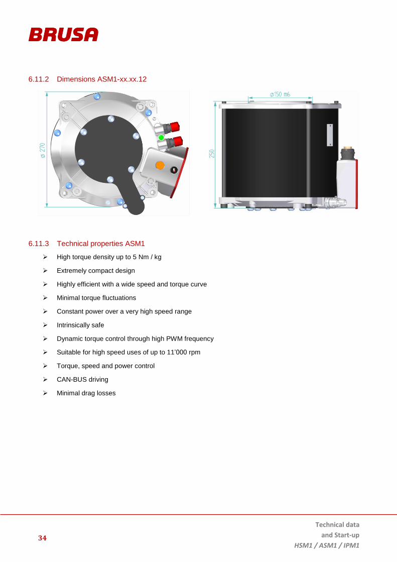
6.11.2 Dimensions ASM1-xx.xx.12
6.11.3 Technical properties ASM1
High torque density up to 5 Nm / kg
Extremely compact design
Highly efficient with a wide speed and torque curve
Minimal torque fluctuations
Constant power over a very high speed range
Intrinsically safe
Dynamic torque control through high PWM frequency
Suitable for high speed uses of up to 11’000 rpm
Torque, speed and power control
CAN-BUS driving
Minimal drag losses
35
Technical data
and Start-up
HSM1 / ASM1 / IPM1
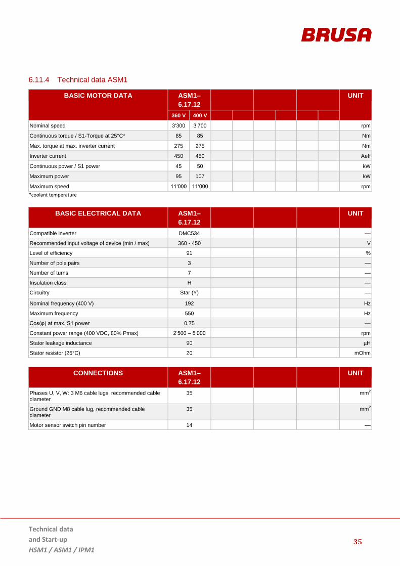
6.11.4 Technical data ASM1
BASIC MOTOR DATA ASM1–
6.17.12
UNIT
360 V 400 V
Nominal speed 3‘300 3‘700 rpm
Continuous torque / S1-Torque at 25°C* 85 85 Nm
Max. torque at max. inverter current 275 275 Nm
Inverter current 450 450 Aeff
Continuous power / S1 power 45 50 kW
Maximum power 95 107 kW
Maximum speed 11‘000 11‘000 rpm
*coolant temperature
BASIC ELECTRICAL DATA ASM1–
6.17.12
UNIT
Compatible inverter DMC534 ––
Recommended input voltage of device (min / max) 360 - 450 V
Level of efficiency 91 %
Number of pole pairs 3 ––
Number of turns 7 ––
Insulation class H ––
Circuitry Star (Y) ––
Nominal frequency (400 V) 192 Hz
Maximum frequency 550 Hz
Cos(φ) at max. S1 power 0.75 ––
Constant power range (400 VDC, 80% Pmax) 2‘500 – 5‘000 rpm
Stator leakage inductance 90 µH
Stator resistor (25°C) 20 mOhm
CONNECTIONS ASM1–
6.17.12
UNIT
Phases U, V, W: 3 M6 cable lugs, recommended cable diameter
35 mm2
Ground GND M8 cable lug, recommended cable diameter
35 mm2
Motor sensor switch pin number 14 ––

Technical data
and Start-up
HSM1 / ASM1 / IPM1
36
BASIC MECHANICAL DATA ASM1–
6.17.12
EINHEIT
Cooling jacket diameter 270 mm
Total length 245 mm
Stator diameter 240 mm
Rotor diameter 165 mm
Active length 123 mm
Active mass 36.9 Kg
Weight without gear box 55.9 Kg
Rotor inertia torque 0.075 Kg/m²
IP protection IP67 –––
THERMAL / COOLING SYSTEM ASM1–
6.17.12
EINHEIT
Coolant mixture ratio (water / glycol) 50 / 50 –––
Derating temperature range 117 - 160 °C
Maximum operational temperature (activation of overload protection)
170 °C
Amount of coolant in device 0.6 l
Minimum coolant temperature at inlet - 40 °C
Maximum coolant temperature at inlet 65 °C
Flow rate 6 - 8 l/min
Pressure drop @ 6l / min Tcoolant = 25°C
(at standard Norma PS3 90° quick connector)
ca. 150 mbar
Ambient temperature range for storage - 40…+ 85 °C
Ambient temperature range in operation - 40...+ 85 °C

37
Technical data
and Start-up
HSM1 / ASM1 / IPM1
6.12 IPM1
6.12.1 Basic function of the IPM1 internal permanently excited synchronous motor
The IPM1 is a water-cooled 3-phase AC motor like the HSM1. The base of the IPM1 forms a rotor with internal
permanent magnets which helps the engine to an extremely high level of efficiency, with minimal rotor temperature.
The IPM1 has been designed and optimized for a maximum of continuous power at a high efficiency. The IPM1
reaches a constant torque for speeds up to 7000 rpm. For implementation as a generator, the IMP1 is suitable for 1
- or 2 - cylinder range extender combustion engines or as traction drive for motorcycle or light vehicle applications.
The IPM1 motor offers additional advantages from a general viewpoint:
Low manufacturing costs due to uncomplex construction
Very little drag loss
Can be used as a motor or a generator
Intrinsically safe in case of faulty events
No voltage generation during forced drive (e.g. towing)
Consistently high torque
Very long lifespan
To achieve optimum results with this motor, it is paramount that the connected inverter is exactly adjusted to the
motor. Inverters of the company BRUSA Elektronik AG are already specially optimised for use with the IPM1.
Technical data
and Start-up
HSM1 / ASM1 / IPM1
38
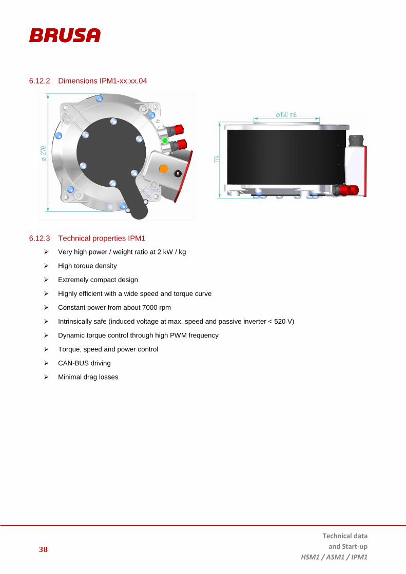
6.12.2 Dimensions IPM1-xx.xx.04
6.12.3 Technical properties IPM1
Very high power / weight ratio at 2 kW / kg
High torque density
Extremely compact design
Highly efficient with a wide speed and torque curve
Constant power from about 7000 rpm
Intrinsically safe (induced voltage at max. speed and passive inverter < 520 V)
Dynamic torque control through high PWM frequency
Torque, speed and power control
CAN-BUS driving
Minimal drag losses

39
Technical data
and Start-up
HSM1 / ASM1 / IPM1
6.12.4 Technical data IPM1
BASIC MOTOR DATA IPM1–
6.17.04
UNIT
360 V 400 V
Corner speed max. Torque / max. Power 6‘700 7‘500 rpm
Nominal speed S1 / 25°C* 7‘200 8‘000 rpm
Continuous torque / S1-Torque at 25°C* 40 40 Nm
Max. torque at max. inverter current 72 72 Nm
Continuous power / S1 power 30 33 kW
Maximum power 50 56 kW
Maximum speed 10‘000 10‘000 rpm
*coolant temperature
BASIC ELECTRICAL DATA IPM1–
6.17.04
UNIT
Compatible inverter DMC514 ––
Recommended input voltage of device (min / max) 360 - 450 V
Level of efficiency 95 %
Number of pole pairs 3 ––
Number of turns 14 ––
Insulation class H ––
Circuitry Star (Y) ––
Nominal frequency (400 V) 375 Hz
Maximum frequency 500 Hz
Cos(φ) at max. S1 power 0.96 ––
Constant power range (400 VDC, 80% Pmax) 7‘000 – 10‘000 rpm
Max. motor flux 0.0781 Vs
Stator leakage inductance 43 µH
Stator resistor (25°C) 59 mOhm
CONNECTIONS IPM1–
6.17.04
UNIT
Phases U, V, W: 3 M6 cable lugs, recommended cable diameter
25 mm2
Ground GND M8 cable lug, recommended cable diameter
25 mm2
Motor sensor switch pin number 14 ––

Technical data
and Start-up
HSM1 / ASM1 / IPM1
40
BASIC MECHANICAL DATA IPM1–
6.17.04
EINHEIT
Cooling jacket diameter 270 mm
Total length 168 mm
Stator diameter 240 mm
Rotor diameter 165 mm
Active length 41 mm
Active mass 12.5 Kg
Weight without gear box 29 Kg
Rotor inertia torque 0.023 Kg/m²
IP protection IP67 –––
Magnet material NeFeB –––
THERMAL / COOLING SYSTEM IPM1–
6.17.04
EINHEIT
Coolant mixture ratio (water / glycol) 50 / 50 –––
Derating temperature range 132 - 160 °C
Maximum operational temperature (activation of overload protection)
170 °C
Amount of coolant in device 0.4 l
Minimum coolant temperature at inlet - 40 °C
Maximum coolant temperature at inlet + 65 °C
Flow rate 6-8 l/min
Pressure drop @ 6l / min Tcoolant = 25°C
(at standard Norma PS3 90° quick connector)
ca. 120 mbar
Ambient temperature range for storage - 40...+85 °C
Ambient temperature range in operation - 40...+85 °C

41
Technical data
and Start-up
HSM1 / ASM1 / IPM1
6.13 Mechanical connections
6.13.1 Fixing points HSM1 / ASM1 / IPM1
DETAIL FIXING POINTS
1
Fixing points on the end shield without Helicoil insert with M10 standard thread
ISO 4017-M10x35-8.8-A2K
typical tightening torque: 38 ±6 Nm
2
Fixing points M12 without Helicoil:
hexagon head screw with fine threads
ISO 8676-M12x1.5x35-8.8-A2K
typical tightening torque: 70 ± 10 Nm
Fixing points M10 with Helicoil
hexagon head screw standard thread
ISO 4017-M10x35-8.8-A2K
typical tightening torque: 41 ± 6 Nm

Technical data
and Start-up
HSM1 / ASM1 / IPM1
42
DETAIL BEFESTIGUNGSPUNKTE
3
The use of adapter sleeves (outer–Ø 13 mm) is possible at this positions (illustration)
Fixing points M12 without Helicoil:
hexagon head screw with fine thread
ISO 8676-M12x1.5x35-8.8-A2K
typical tightening torque: 70 ± 10 Nm
Fixing points M10 with Helicoil
hexagon head screw standard thread
ISO 4017-M10x35-8.8-A2K
typical tightening torque: 41 ± 6 Nm
INSTRUCTION
Assembly instructions fixing point 1:
A minimum thread oft he screws ≥ 15mm is recommended (note devices drawing).
Assembly instructions fixing point 2 and 3:
BRUSA recommends using a Helicoil insert, type: HELICOIL ® M12x1.5 x 10mm.
A minimum thread oft he screws ≥ 10mm is recommended (note devices drawing).

43
Technical data
and Start-up
HSM1 / ASM1 / IPM1
6.13.2 Cooling system
INSTRUCTION
Observe the cooling liquid mixture ratio (water / glycol) which is adapted to the outside temperature! You can find information on the mixture ratio in the manufacturer's technical data.
1. Cooling water outlet connection 2. Cooling water inlet connection
3. Cooling system ventilation screw
6.13.3 Cooling water connections
Quick connector for cooling water connection pieces
90° Norma PS3 (MHAA776)
Quick connector for cooling water connection pieces
0° Norma PS3 (MHAA775)
Quick connector for cooling water connection pieces
M18 x 1.5 (MAAA366)
2 1
3
Technical data
and Start-up
HSM1 / ASM1 / IPM1
44
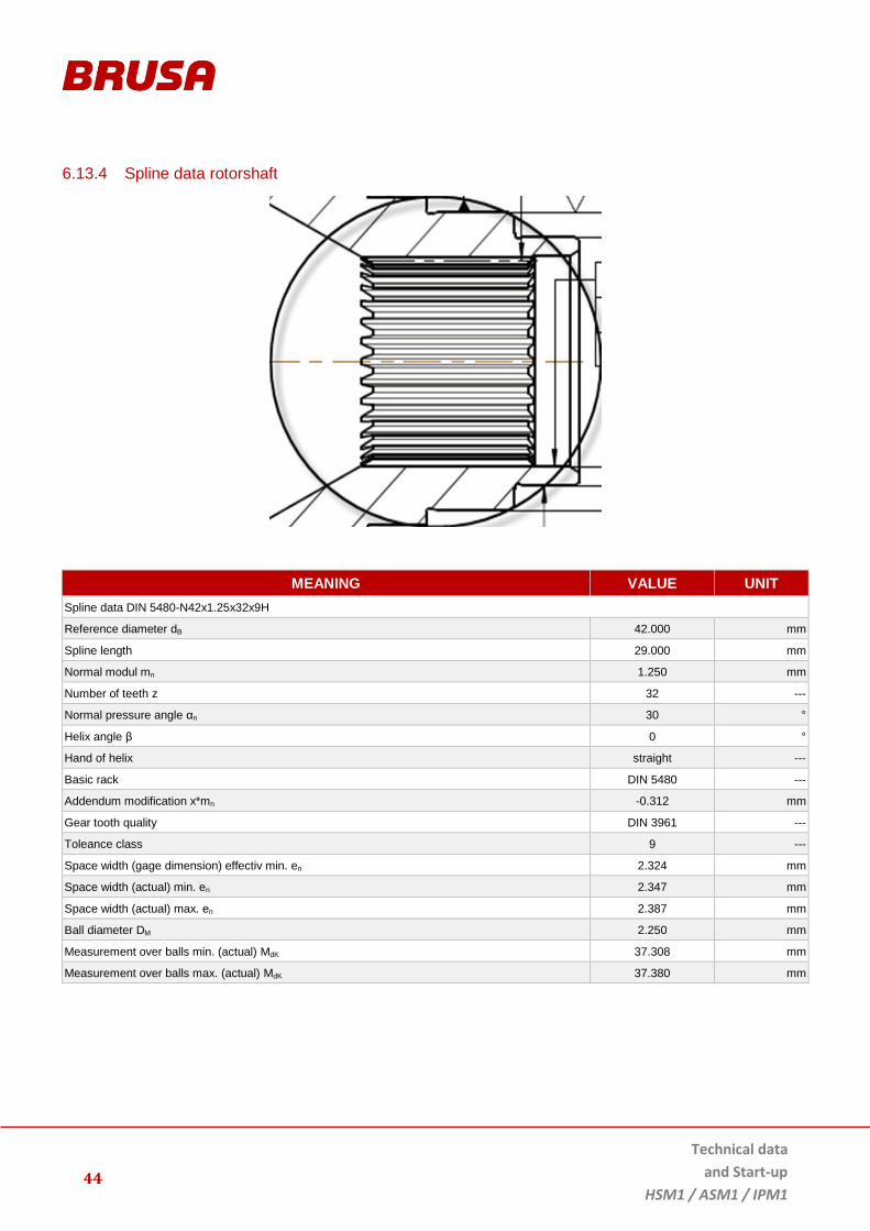
6.13.4 Spline data rotorshaft
MEANING VALUE UNIT
Spline data DIN 5480-N42x1.25x32x9H
Reference diameter dB 42.000 mm
Spline length 29.000 mm
Normal modul mn 1.250 mm
Number of teeth z 32 ---
Normal pressure angle αn 30 °
Helix angle β 0 °
Hand of helix straight ---
Basic rack DIN 5480 ---
Addendum modification x*mn -0.312 mm
Gear tooth quality DIN 3961 ---
Toleance class 9 ---
Space width (gage dimension) effectiv min. en 2.324 mm
Space width (actual) min. en 2.347 mm
Space width (actual) max. en 2.387 mm
Ball diameter DM 2.250 mm
Measurement over balls min. (actual) MdK 37.308 mm
Measurement over balls max. (actual) MdK 37.380 mm
45
Technical data
and Start-up
HSM1 / ASM1 / IPM1
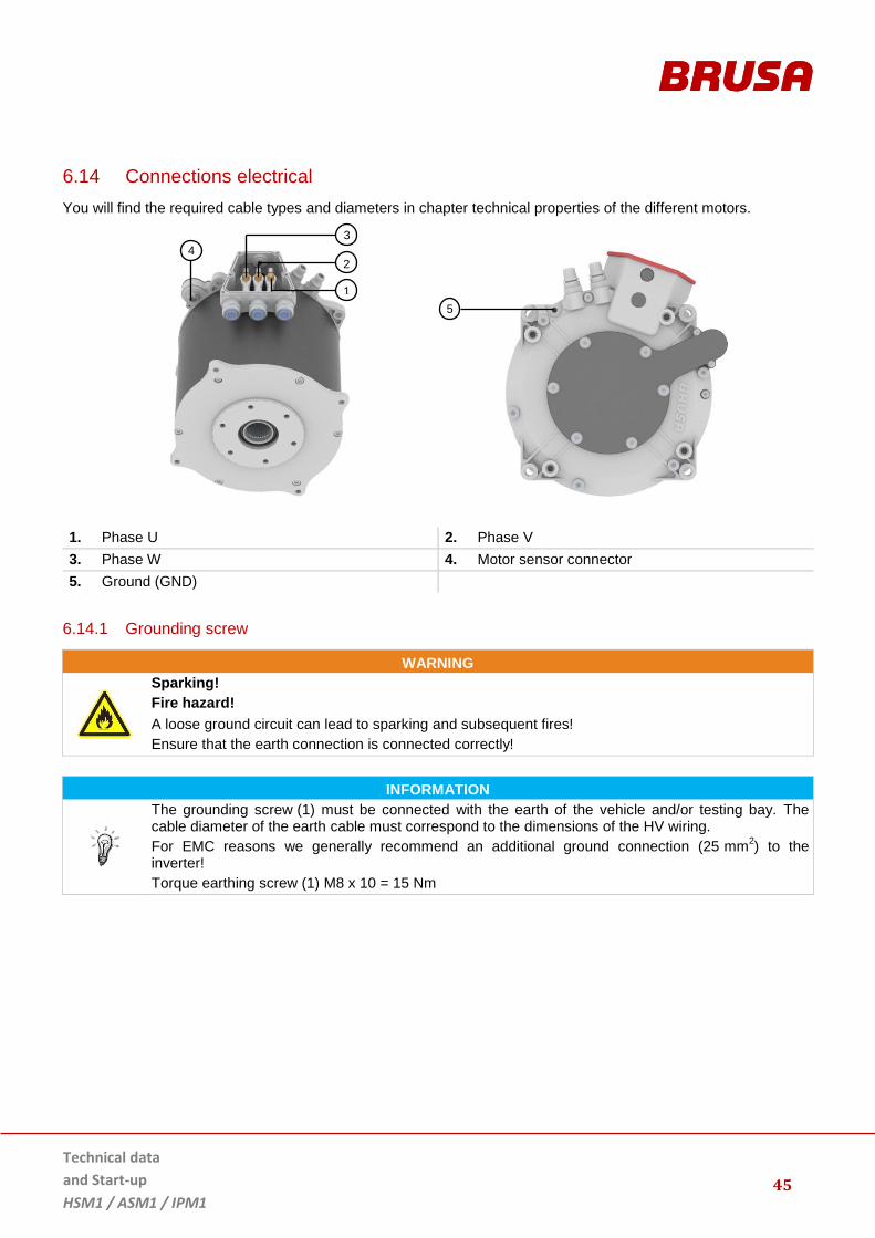
6.14 Connections electrical
You will find the required cable types and diameters in chapter technical properties of the different motors.
1. Phase U 2. Phase V
3. Phase W 4. Motor sensor connector
5. Ground (GND)
6.14.1 Grounding screw
WARNING
Sparking!
Fire hazard!
A loose ground circuit can lead to sparking and subsequent fires!
Ensure that the earth connection is connected correctly!
INFORMATION
The grounding screw (1) must be connected with the earth of the vehicle and/or testing bay. The cable diameter of the earth cable must correspond to the dimensions of the HV wiring.
For EMC reasons we generally recommend an additional ground connection (25 mm2) to the
inverter!
Torque earthing screw (1) M8 x 10 = 15 Nm
1
2
3
4
5

Technical data
and Start-up
HSM1 / ASM1 / IPM1
46
6.14.2 Motor sensor connection PIN assignment (motor side)
INFORMATION
The pin assignment of the motor sensor connection is BRUSA specific and deviates from the standard pin assignment of the cable manufacturer!
1. POS3 6 bit absolute position bit 3 2. POS4 6 bit absolute position bit 4
3. POS5 6 bit absolute position bit 6 4. GND-NTC Earth NTC / PTC
5. NTC Motor temperature sensor 6. PTC Motor overheat switch-off
7. VCC-
GEB
Motor sensor – supply voltage 6 VDC 8. POS0 6 bit absolute position bit 0
9. POS1 6 bit absolute position bit 1 10. POS2 6 bit absolute position bit 2
11. GND Earth 12. MOTB Motor B (incremental)
13. MOTA Motor A (incremental) 14. UPD Position update data
15. --- Centering groove

47
Technical data
and Start-up
HSM1 / ASM1 / IPM1
7 Profiles and diagrams
7.1 HSM1–6.17.12
7.1.1 Power / torque depending on speed
400 V / 300 A HSM1-6.17.12
400 V / 450 A HSM1-6.17.12
0
20
40
60
80
100
120
0
40
80
120
160
200
240
0 2000 4000 6000 8000 10000 12000M
ech
. p
ow
er
[kW
]
To
rqu
e [
Nm
]
Speed [rpm]
cont. torque [Nm]
max. torque [Nm]
cont. power [kW]
max. power [kW]
0
20
40
60
80
100
120
140
0
50
100
150
200
250
300
350
0 2000 4000 6000 8000 10000 12000
Me
ch
. p
ow
er
[kW
]
To
rqu
e [
Nm
]
Speed [rpm]
cont. torque [Nm]
max. torque [Nm]
cont. power [kW]
max. power [kW]
Technical data
and Start-up
HSM1 / ASM1 / IPM1
48
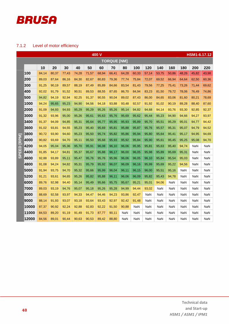
7.1.2 Level of motor efficiency
400 V HSM1-6.17.12
TORQUE [NM]
10 20 30 40 50 60 70 80 100 120 140 160 180 200 220
SP
EE
D [
RP
M]
100 84,14 80,37 77,43 74,28 71,57 68,94 66,41 64,28 60,33 57,14 53,75 50,86 48,26 45,82 43,98
200 89,03 87,64 86,16 84,30 82,67 80,83 79,36 77,74 75,84 72,07 69,52 66,94 64,64 62,50 60,36
300 91,25 90,19 89,57 88,19 87,49 85,89 84,66 83,54 81,43 79,56 77,25 75,41 73,26 71,44 69,62
400 92,02 91,79 91,52 90,51 89,53 88,55 87,65 86,70 84,94 83,23 81,50 79,72 78,06 76,49 74,86
500 94,82 94,19 92,94 92,25 91,37 90,55 90,04 89,02 87,43 86,00 84,65 83,06 81,60 80,21 78,69
1000 94,24 95,65 95,23 94,90 94,56 94,18 93,88 93,48 92,57 91,92 91,02 90,19 89,28 88,40 87,60
2000 91,09 94,93 94,93 95,29 95,29 95,26 95,26 95,14 94,82 94,68 94,14 93,76 93,30 92,85 92,37
3000 91,32 93,96 95,00 95,26 95,61 95,63 95,76 95,69 95,62 95,44 95,23 94,90 94,66 94,27 93,97
3400 91,37 94,09 94,85 95,31 95,64 95,77 95,95 95,93 95,89 95,70 95,51 95,29 95,01 94,77 94,42
3600 91,02 93,81 94,55 95,23 95,40 95,69 95,81 95,88 95,87 95,76 95,57 95,31 95,07 94,79 94,52
3800 90,72 93,90 94,60 95,23 95,50 95,74 95,82 95,86 95,94 95,80 95,64 95,41 95,17 94,95 94,69
4000 90,82 93,69 94,70 95,11 95,50 95,68 95,93 95,92 95,84 95,90 95,61 95,45 95,25 95,08 94,70
4200 94,05 95,04 95,36 95,70 95,91 96,08 96,10 96,06 95,95 95,81 95,63 95,40 94,74 NaN NaN
4400 91,85 94,17 94,81 95,37 95,67 95,88 96,17 96,00 96,05 95,98 95,89 95,69 95,31 NaN NaN
4600 92,88 93,89 95,11 95,47 95,76 95,76 95,96 96,06 96,05 96,10 95,84 95,54 95,03 NaN NaN
4800 91,08 94,24 94,82 95,31 95,79 95,92 96,07 96,09 96,16 95,99 95,69 95,22 94,56 NaN NaN
5000 91,94 93,75 94,70 95,32 95,66 95,99 96,04 96,11 96,15 96,00 95,51 95,16 NaN NaN NaN
5200 91,21 93,61 94,65 95,26 95,82 95,88 96,11 96,06 96,09 95,82 95,43 94,78 NaN NaN NaN
6000 89,76 92,98 94,40 95,14 95,49 95,66 95,75 95,67 95,21 95,01 94,06 NaN NaN NaN NaN
7000 89,03 93,19 94,76 95,07 95,18 95,26 95,28 94,99 94,44 93,02 NaN NaN NaN NaN NaN
8000 88,69 92,58 93,97 94,33 94,47 94,46 94,23 93,86 92,47 NaN NaN NaN NaN NaN NaN
9000 88,14 91,93 93,07 93,18 93,64 93,43 92,97 92,42 91,48 NaN NaN NaN NaN NaN NaN
10000 87,37 90,92 92,24 92,88 92,83 92,22 91,50 90,88 NaN NaN NaN NaN NaN NaN NaN
11000 84,53 89,20 91,19 91,49 91,73 87,77 90,11 NaN NaN NaN NaN NaN NaN NaN NaN
12000 84,56 89,01 90,44 90,63 90,53 89,42 88,80 NaN NaN NaN NaN NaN NaN NaN NaN

49
Technical data
and Start-up
HSM1 / ASM1 / IPM1
7.1.3 Level of generator efficiency (recuperation)
400 V HSM1-6.17.12
SP
EE
D [
RP
M]
TORQUE [NM]
-10 -20 -30 -40 -50 -60 -70 -80 -100 -120 -140 -160 -180 -200 -220
100 80,65 75,34 70,07 64,47 58,79 53,41 47,78 42,27 41,36 40,44 39,52 38,61 37,69 36,78 35,86
200 87,55 86,18 83,82 81,12 78,81 76,06 73,31 70,55 65,43 60,28 54,99 49,34 43,68 38,40 36,63
300 88,87 89,38 88,42 87,06 85,29 83,81 82,21 80,51 77,31 73,93 70,54 66,91 63,33 60,24 55,18
400 89,18 91,08 89,98 89,06 88,08 86,89 85,86 84,69 82,30 79,95 77,44 74,73 71,94 69,53 66,65
500 93,95 93,19 92,57 91,68 90,66 89,70 88,79 87,77 85,85 83,84 81,89 79,67 77,43 75,27 73,04
1000 95,63 95,09 94,77 94,41 94,17 93,71 93,42 92,92 92,06 91,13 90,07 89,10 87,99 86,90 85,83
2000 91,68 94,05 94,46 94,96 95,06 95,01 95,05 94,88 94,62 94,28 93,83 93,26 92,80 92,27 91,68
3000 89,95 93,29 94,95 95,02 95,27 95,33 95,48 95,43 95,37 95,23 94,97 94,68 94,35 94,00 93,57
3400 90,28 93,53 94,25 94,90 95,43 95,50 95,62 95,61 95,61 95,43 95,19 94,96 94,61 94,42 94,04
3600 89,69 93,08 94,30 94,95 95,28 95,41 95,59 95,54 95,63 95,49 95,32 95,02 94,78 94,49 94,18
3800 89,83 93,41 94,38 94,98 95,26 95,51 95,66 95,71 95,72 95,60 95,47 95,27 94,97 94,72 94,39
4000 89,90 93,42 94,13 94,76 95,27 95,48 95,61 95,69 95,69 95,63 95,50 95,25 95,03 94,76 94,53
4200 89,82 93,44 94,61 95,14 95,37 95,50 95,72 95,78 95,81 95,77 95,58 95,34 95,21 94,97 94,69
4400 90,86 93,44 94,54 95,21 95,53 95,67 95,82 95,89 95,78 95,69 95,45 95,24 94,93 94,66 94,40
4600 90,64 93,41 94,45 95,25 95,47 95,63 95,73 95,85 95,96 95,84 95,67 95,57 95,40 95,14 94,85
4800 90,29 93,45 94,39 95,13 95,45 95,62 95,87 95,89 96,05 95,88 95,74 95,61 95,38 95,16 NaN
5000 90,15 93,39 94,37 95,09 95,43 95,64 95,68 95,83 96,03 95,94 95,85 95,62 95,39 95,04 NaN
5200 89,16 93,25 94,51 94,97 95,42 95,72 95,74 95,96 96,13 96,08 95,74 95,62 95,28 NaN NaN
6000 89,00 92,85 94,21 94,70 95,32 95,54 95,73 95,77 95,72 95,53 95,23 94,71 NaN NaN NaN
7000 89,15 92,52 94,14 94,93 95,10 95,34 95,41 95,31 95,16 94,64 NaN NaN NaN NaN NaN
8000 89,19 92,69 93,99 94,51 94,94 94,82 94,78 94,63 94,28 NaN NaN NaN NaN NaN NaN
9000 86,96 91,64 93,24 93,56 94,16 93,95 93,80 93,37 92,22 NaN NaN NaN NaN NaN NaN
10000 86,60 91,46 92,50 92,95 93,17 93,15 92,72 92,10 90,29 NaN NaN NaN NaN NaN NaN
11000 85,75 90,88 91,34 92,08 91,88 91,96 91,52 90,30 NaN NaN NaN NaN NaN NaN NaN
12000 81,48 85,79 85,69 91,61 90,97 NaN NaN NaN NaN NaN NaN NaN NaN NaN NaN

Technical data
and Start-up
HSM1 / ASM1 / IPM1
50
7.1.4 S1 torque
S1 TORQUE AT 25°C / 5200 RPM HSM1-6.17.12
S1 TORQUE AT 65°C / 5600 RPM HSM1-6.17.12
0
20
40
60
80
100
120
140
160
0:0
0
0:0
5
0:1
0
0:1
5
0:2
0
0:2
5
0:3
0
0:3
5
0:4
0
0:4
5
0:5
0
0:5
5
1:0
0
1:0
5
1:1
0
1:1
5
1:2
0
1:2
5
1:3
0
1:3
5
1:4
0
1:4
5
1:5
0
1:5
5
2:0
0
Sh
aft
To
rqu
e [
Nm
] T
em
pera
ture
[°
C]
Me
ch
an
ica
l P
ow
er
[KW
]
Time [hh:mm ] Shaft torque
DMC motor temperature
Mechanical power
Power losses
0
20
40
60
80
100
120
140
160
0:0
0
0:0
7
0:1
4
0:2
1
0:2
8
0:3
6
0:4
3
0:5
0
0:5
7
1:0
4
1:1
2
1:1
9
1:2
6
1:3
3
1:4
0
1:4
8
Sh
aft
To
rqu
e [
Nm
] T
em
pera
ture
[°
C]
Me
ch
an
ica
l P
ow
er
[KW
]
Time [hh:mm] Shaft torque
DMC motor temperature
Mechanical power
Power losses

51
Technical data
and Start-up
HSM1 / ASM1 / IPM1
7.1.5 Thermal behaviour / derating
AT 25°C HSM1-6.17.12
Test period 30 min
Voltage 400 V
Speed (number of revolutions) 5200 rpm
Maximum power 74,2 kW
Cooling water temperature 25 °C
AT 65°C HSM1-6.17.12
Test period 30 min
Voltage 400 V
Speed (number of revolutions) 5600 rpm
Maximum power 63,4 kW
Cooling water temperature 65 °C
0
50
100
150
200
00:00 05:00 10:00 15:00 20:00 25:00 30:00
Time [min]
Mech. Power [kW]
Shaft Torque [Nm]
Stator Winding Temp. [˚C]
0
50
100
150
200
00:00 05:00 10:00 15:00 20:00 25:00 30:00
Time [min]
Mech. Power [kW]
Shaft Torque [Nm]
Stator Winding Temp. [˚C]

Technical data
and Start-up
HSM1 / ASM1 / IPM1
52
AT 25°C HSM1-6.17.12
Test period 5 min
Voltage 400 V
Speed (number of revolutions) 4000 rpm
Maximum power 77.7 kW
Cooling water temperature 25 °C
AT 25°C HSM1-6.17.12
Test period 5 min
Voltage 400 V
Speed (number of revolutions) 5400 rpm
Maximum power 85.1 kW
Cooling water temperature 25 °C
0
50
100
150
200
250
00:00 00:30 01:00 01:30 02:00 02:30 03:00 03:30 04:00 04:30 05:00
time [min]
Mech. Power [kW]
Shaft Torque [Nm]
Stator Winding Temp. [˚C]
0
50
100
150
200
250
00:00 00:30 01:00 01:30 02:00 02:30 03:00 03:30 04:00 04:30 05:00
time [min]
Mech. Power [kW]
Shaft Torque [Nm]
Stator Winding Temp. [˚C]

53
Technical data
and Start-up
HSM1 / ASM1 / IPM1
AT 65°C HSM1-6.17.12
Test period 5 min
Voltage 400 V
Speed (number of revolutions) 4000 rpm
Maximum power 62 kW
Cooling water temperature 65 °C
AT 65°C HSM1-6.17.12
Test period 5 min
Voltage 400 V
Speed (number of revolutions) 5400 rpm
Maximum power 72.3 kW
Cooling water temperature 65 °C
0
50
100
150
200
250
00:00 00:30 01:00 01:30 02:00 02:30 03:00 03:30 04:00 04:30 05:00
time [min]
Mech. Power [kW]
Shaft Torque [Nm]
Stator Winding Temp. [˚C]
0
50
100
150
200
250
00:00 00:30 01:00 01:30 02:00 02:30 03:00 03:30 04:00 04:30 05:00
time [min]
Mech. Power [kW]
Shaft Torque [Nm]
Stator Winding Temp. [˚C]

Technical data
and Start-up
HSM1 / ASM1 / IPM1
54
7.1.6 Induced motor voltage
HSM1-6.17.12
7.1.7 Short circuit torque
SHORT CIRCUIT MEASUREMENT 3PH. AT 25°C HSM1-6.17.12
0
50
100
150
200
250
300
350
400
450
500
0 2000 4000 6000 8000 10000 12000
Vo
ltag
e [
V]
Speed [rpm]
Phase voltage RMS
Rectified induced motorvoltage
0
60
120
180
240
-80
-70
-60
-50
-40
-30
-20
-10
0
0 2'000 4'000 6'000 8'000 10'000 12'000
Ph
as
e C
urr
en
t [A
rms
]
To
rqu
e [
Nm
]
Speed [rpm] Shaft torque
Phase current

55
Technical data
and Start-up
HSM1 / ASM1 / IPM1
7.2 HSM1-10.18.13
7.2.1 Power / torque depending on speed
400 V HSM1-10.18.13
0
40
80
120
160
0
40
80
120
160
200
240
280
320
0 2000 4000 6000 8000 10000 12000 14000
Me
ch
. p
ow
er
[kW
]
To
rqu
e [
Nm
]
Speed [rpm]
cont. torque [Nm]
max. torque [Nm]
cont. power [kW]
max. power [kW]

Technical data
and Start-up
HSM1 / ASM1 / IPM1
56
7.2.2 Level of motor efficiency
HSM1-10.18.13
TORQUE [NM]
SP
EE
D [
RP
M]
10 20 30 40 50 60 70 80 100 120 140 160 180 200 220 240 260 280 300
4000 89,19 93,17 94,36 94,89 95,38 95,76 95,88 96,10 96,12 96,09 96,06 95,88 95,68 95,45 95,17 94,86 94,51 94,15 93,94
4500 89,17 93,17 94,41 95,02 95,55 95,80 95,93 96,04 96,22 96,22 96,06 96,01 95,71 95,52 95,25 94,94 94,65 94,29 93,92
4800 89,69 90,46 92,48 93,62 94,31 94,77 95,12 95,29 95,56 95,67 95,67 95,59 95,49 95,31 95,03 94,80 94,45 93,95 NaN
5000 89,66 93,37 94,51 95,01 95,58 95,87 96,05 96,14 96,29 96,26 96,16 96,07 95,87 95,68 95,41 95,07 94,55 NaN NaN
5500 89,21 93,17 94,45 95,06 95,49 95,74 95,89 96,09 96,19 96,21 96,18 96,00 95,77 95,40 94,89 94,23 93,51 NaN NaN
6000 89,39 92,97 94,23 94,97 95,33 95,72 95,84 96,01 96,18 96,16 96,01 95,71 95,29 94,76 93,97 92,97 NaN NaN NaN
6500 88,82 92,75 94,04 94,68 95,13 95,57 95,83 95,95 96,05 95,95 95,66 95,28 94,69 93,76 92,47 NaN NaN NaN NaN
7000 86,30 91,41 93,08 93,92 94,83 95,21 95,47 95,67 95,63 95,52 95,12 94,57 93,61 92,06 NaN NaN NaN NaN NaN
7500 84,80 90,72 92,70 93,07 94,70 94,96 95,24 95,31 95,27 95,12 94,57 93,65 92,11 NaN NaN NaN NaN NaN NaN
8000 84,19 90,19 94,13 94,15 94,56 94,90 95,07 95,09 94,94 94,64 93,92 92,08 NaN NaN NaN NaN NaN NaN NaN
9000 83,39 90,36 92,93 93,68 94,19 94,41 94,49 94,42 94,29 93,52 91,35 NaN NaN NaN NaN NaN NaN NaN NaN
10000 83,13 90,39 92,38 93,26 93,63 93,74 93,82 93,70 93,17 NaN NaN NaN NaN NaN NaN NaN NaN NaN NaN
11000 82,56 89,44 91,80 92,28 92,91 93,03 93,12 92,83 NaN NaN NaN NaN NaN NaN NaN NaN NaN NaN NaN
12000 81,16 88,10 90,70 91,62 92,48 91,84 91,83 91,36 NaN NaN NaN NaN NaN NaN NaN NaN NaN NaN NaN
7.2.3 Induced motor voltage
HSM1-10.18.13
0
100
200
300
400
500
600
0 2000 4000 6000 8000 10000 12000 14000
Vo
ltag
e [
V]
Speed [rpm]
Phase Voltage RMS
Rectified inducedmotor Voltage

57
Technical data
and Start-up
HSM1 / ASM1 / IPM1
7.2.4 Short circuit torque
SHORT CIRCUIT MEASUREMENT 3PH. AT 25°C HSM1-10.18.13
0
50
100
150
200
250
300
-100
-90
-80
-70
-60
-50
-40
-30
-20
-10
0
0 2'000 4'000 6'000 8'000 10'000 12'000
Cu
rre
nt
[Arm
s]
Sh
aft
_T
orq
ue
[N
m]
Rotational_speed [rpm] Shaft_Torque
Current_RMS

Technical data
and Start-up
HSM1 / ASM1 / IPM1
58
7.3 HSM1–10.18.04
7.3.1 Power / torque depending on speed
400 V HSM1-10.18.04
0
10
20
30
40
50
60
0
20
40
60
80
100
120
0 2000 4000 6000 8000 10000 12000 14000M
ech
. p
ow
er
[kW
]
To
rqu
e [
Nm
]
Speed [rpm]
cont. torque [Nm]
max. torque [Nm]
cont. power [kW]
max. power [kW]

59
Technical data
and Start-up
HSM1 / ASM1 / IPM1
7.3.2 Level of motor efficiency
HSM1-10.18.04
TORQUE [NM]
SPEE
D [
RP
M]
0 10 20 30 40 50 60 70 80 90 100
1000 87.81 89.92 90.00 89.21 88.11 86.79 85.37 83.81 81.87 80.01
2000 89.93 92.54 93.26 92.96 92.63 91.99 90.81 89.65 88.16 86.71
3000 92.06 93.39 94.68 94.56 94.35 93.55 92.98 92.50 91.60 90.80
4000 94.15 95.22 94.92 94.79 94.65 93.94 93.38 93.02 91.86 91.14
5000 92.69 94.29 94.70 94.50 94.49 94.05 93.35 92.21 91.11 90.30
6000 90.81 93.29 94.05 94.19 93.88 92.98 90.79 90.59 90.37
7000 90.05 92.66 93.67 93.64 92.78 90.50 90.20
8000 87.24 91.70 92.54 91.95 89.89 88.95
9000 87.66 91.35 91.61 89.87 89.47
10000 87.39 90.51 90.49 88.33
11000 86.22 89.90 89.03 88.20
12000 85.10 87.46 88.46

Technical data
and Start-up
HSM1 / ASM1 / IPM1
60
7.3.3 Induced motor voltage
HSM1-10.18.04
0
50
100
150
200
250
300
350
400
450
500
0 2000 4000 6000 8000 10000 12000
Vo
lta
ge
[V
]
Speed [rpm]
Phase voltage RMS
Rectified induced motorvoltage

61
Technical data
and Start-up
HSM1 / ASM1 / IPM1
7.4 HSM1-10.18.22
7.4.1 Power / torque depending on speed
400 V HSM1-10.18.22

Technical data
and Start-up
HSM1 / ASM1 / IPM1
62
7.4.2 Level of motor efficiency
HSM1-10.18.22

63
Technical data
and Start-up
HSM1 / ASM1 / IPM1
7.4.3 Induced motor voltage
HSM1-10.18.22
0
100
200
300
400
500
600
0 2000 4000 6000 8000 10000 12000
Vo
ltag
e [
V]
Speed [rpm]
Phase Voltage RMS
Rectified induced motorVoltage

Technical data
and Start-up
HSM1 / ASM1 / IPM1
64
7.5 ASM1–6.17.12
7.5.1 Power / torque depending on speed
400 V ASM1–6.17.12
0
20
40
60
80
100
120
0
50
100
150
200
250
300
0 2000 4000 6000 8000 10000 12000
Me
ch
. p
ow
er
[kW
]
To
rqu
e [
Nm
]
Speed [rpm]
cont. torque [Nm]
max. torque [Nm]
cont. power [kW]
max. power [kW]

65
Technical data
and Start-up
HSM1 / ASM1 / IPM1
7.6 IPM1–6.17.04
7.6.1 Power / torque depending on speed
400 V IPM1-6.17.04
0
25
50
75
100
0
20
40
60
80
0 2000 4000 6000 8000 10000
me
ch
. P
ow
er
[kW
]
To
rqu
e [
Nm
]
Speed [rpm]
cont. torque [Nm]
max. torque [Nm]
cont. power [kW]
max. power [kW]

Technical data
and Start-up
HSM1 / ASM1 / IPM1
66
7.6.2 Level of motor efficiency
400 V IPM1-6.17.04
Torque [Nm]
Speed
[rpm
]
10 20 30 40 50 60 70
1000 93.00 91.70 88.78 86.23 83.11 79.72 76.54
2000 94.87 94.30 93.05 91.33 89.46 87.17 84.67
3000 95.80 95.15 94.30 93.27 92.18 90.24 88.06
4000 95.82 95.56 95.03 93.99 93.24 91.86 90.55
5000 93.80 95.00 95.25 94.39 93.95 92.56 91.33
6000 92.08 94.48 94.86 94.45 94.07 93.33 92.26
7000 90.53 94.01 94.58 94.45 94.25 93.34 91.74
8000 89.42 93.75 94.20 94.31 93.70 92.42 90.85
9000 87.41 93.59 94.36 93.89 93.01 90.85 90.85
10000 86.89 92.84 93.48 93.14 91.63 90.50 90.46
7.6.3 Level of generator efficiency (recuperation)
400 V IPM1-6.17.04
Torque [Nm]
Speed
[rpm
]
-10 -20 -30 -40 -50 -60 -70
1000 93.79 90.79 87.00 83.56 81.72 74.07 70.16
2000 95.15 94.46 92.32 91.07 88.57 85.58 81.96
3000 94.92 95.28 93.92 92.93 91.32 89.46 86.79
4000 95.63 95.36 94.72 93.75 92.49 91.08 89.45
5000 93.29 95.21 95.30 94.58 93.50 92.21 90.72
6000 91.33 94.84 94.92 94.55 93.90 92.90 91.46
7000 89.33 94.39 94.57 94.44 94.04 93.42 91.95
8000 88.44 93.56 93.97 94.43 93.93 93.56 91.80
9000 87.56 93.82 94.64 94.46 93.82 92.59 90.83
10000 86.11 93.62 93.90 93.85 92.95 91.55 90.77
67
Technical data
and Start-up
HSM1 / ASM1 / IPM1
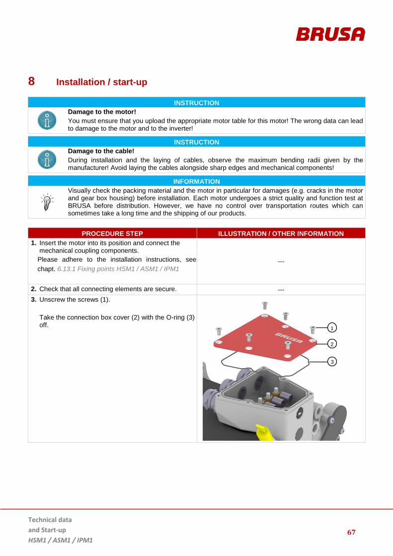
8 Installation / start-up
INSTRUCTION
Damage to the motor!
You must ensure that you upload the appropriate motor table for this motor! The wrong data can lead to damage to the motor and to the inverter!
INSTRUCTION
Damage to the cable!
During installation and the laying of cables, observe the maximum bending radii given by the manufacturer! Avoid laying the cables alongside sharp edges and mechanical components!
INFORMATION
Visually check the packing material and the motor in particular for damages (e.g. cracks in the motor and gear box housing) before installation. Each motor undergoes a strict quality and function test at BRUSA before distribution. However, we have no control over transportation routes which can sometimes take a long time and the shipping of our products.
PROCEDURE STEP ILLUSTRATION / OTHER INFORMATION
1. Insert the motor into its position and connect the mechanical coupling components.
Please adhere to the installation instructions, see
chapt. 6.13.1 Fixing points HSM1 / ASM1 / IPM1
---
2. Check that all connecting elements are secure. ---
3. Unscrew the screws (1).
Take the connection box cover (2) with the O-ring (3) off.
1
2
3

Technical data
and Start-up
HSM1 / ASM1 / IPM1
68
PROCEDURE STEP ILLUSTRATION / OTHER INFORMATION
4. Unscrew the screws (1).
Remove the washers (2).
5. Connect the HV supply and the ground wiring.
See chapt. 8.1 Connecting the HV supply
---
6. Connect the ground wire (1) with the car body and the screw (2).
For EMC reasons we generally recommend an additional ground connection (25 mm
2) to
the inverter!
Torque = 15 Nm
NOTE
Ensure that you connect the phases correctly! Mixing up the phases will lead to a change in the rotating direction of the motor or to malfunctions in the motor depending on the connection version.
7. Connect the HV supply.
Phase U (1)
Phase V (2)
Phase W (3)
Ensure that the cable fittings are positioned correctly and that they are secure.
Torque of screws M6 = 3 Nm
Torque of M25 screw-in plug on connection box = 15 Nm
2
1
3 2 1

69
Technical data
and Start-up
HSM1 / ASM1 / IPM1
INFORMATION
The motor is now ready for operation. During the initial start-up, start the motor with care and caution!
PROCEDURE STEP ILLUSTRATION / OTHER INFORMATION
8. Put the O ring (1) in the guide slot (2).
Screw down the connection box cover (3).
Torque = 5 Nm
---
9. Connect the motor sensor cable (1) with the motor sensor switch (2).
10. Connect the cooling water pumps (1) and (2).
Pay attention while doing so to the cooling water inlet (1) and the cooling water outlet (2).
11. Ventilate the cooling system.
See chapt. 8.2 Ventilating the cooling system
---

Technical data
and Start-up
HSM1 / ASM1 / IPM1
70
8.1 Connecting the HV supply
The building of the HV wiring must be carried out in accordance with the following instructions. Here it is important
that no strands are damaged and that none stick out at the sides on the assembled cable. So check that the screw
connections are correct for each completed cable and that the cable lug is fixed properly (pull test).
For the HV connections we recommend:
A shielded, insulated automotive cable (e.g. Huber & Suhner).
To assemble the cable lugs, using the appropriate crimping tool is absolutely necessary!
INSTRUCTION
Make absolutely sure that the individual strands of the shielding braid (1) do not jut out over the
sealing ring (3) under any circumstances! Once in the integrated state, this will lead to leakages and
subsequently to the leaking of water into the housing!
PROCEDURE STEP ILLUSTRATION / OTHER INFORMATION
1. Insulate 35 mm of the HV cable (1).
Ensure that you do not damage the shielding braid underneath it!
The lengths of the phase cables in the connection box are different, so this will have to be adjusted accordingly for U V W.
2. Shorten the shielding braid (1) by 20 mm.
The cable-side shielding braid (2) must be a length of around 15 mm.

71
Technical data
and Start-up
HSM1 / ASM1 / IPM1
PROCEDURE STEP ILLUSTRATION / OTHER INFORMATION
3. Lead the HV cable (1) through the union nut (2).
Lead the HV cable (1) through the terminal insert (3).
4. Place the terminal insert (1) with the front edge flush with the cable insulation (2).
5. Put the shielding braid (1) over the terminal insert (2).
During this, the shielding braid (1) may overlap the O-Ring (3) by a maximum of 2 mm. Fix the terminal insert (2) in position on the HV cable, eg with electrical tape (4).

Technical data
and Start-up
HSM1 / ASM1 / IPM1
72
PROCEDURE STEP ILLUSTRATION / OTHER INFORMATION
6. Insulate 16 mm of the HV cable (1).
The lengths of the phase cables in the connection box are different, so this will have to be adjusted accordingly for U V W.
7. Assemble the cable lug (1) at the end of the cable.
No strands should stick out at the sides!
The crimping must be hexagonal. Ensure that the crimping has no deformations at the sides because this will make later installations in the housing difficult!
8. Check the secure positioning of the cable lug manually.
---
9. Assemble a shrinkage tube (1) on the cable lug (2).
The assembly of a shrinkage tube (1) is absolutely necessary because otherwise contacting can result in the housing!
INSTRUCTION
During the layout of the cable take care that the first part of the cable is at least 5cm straight before it will be bend to a radius.
WARNING
If you have to reassembly the cable you have to use a new terminal insert. Otherwise it can cause a leakage.
The terminal inserts can be ordered from BRUSA Elektronik AG or directly from hummel.com.
5cm

73
Technical data
and Start-up
HSM1 / ASM1 / IPM1
8.2 Ventilating the cooling system
INSTRUCTION
Air pockets in the cooling passage along with generally insufficient cooling of the motor lead to increased wear!
Ensure that the cooling circuit is fault-free.
PROCEDURE STEP ILLUSTRATION / OTHER INFORMATION
1. Switch on the cooling circuit. ---
2. Place a suitable collection container under the ventilation hole.
---
3. Open the ventilation screw (1).
4. Leave the cooling circuit on until no more air bubbles come out of the ventilation hole.
---
5. Tighten the ventilation screw.
Torque = 7 Nm
---
6. Check the cooling water level. ---
1

Technical data
and Start-up
HSM1 / ASM1 / IPM1
74
8.3 Carrying out the HV test
DANGER
High voltage!
Danger to life!
The motor housing can be live with high voltage during the HV test! Under no circumstances should you touch the motor housing!
Only carry out the test in a secure environment (no access by outside persons possible)!
INSTRUCTION
Destruction of the stator windings!
You must adhere to the given test voltage and testing time!
Exceeding this test voltage and testing time can lead to damage to the motor!
INFORMATION
The HV test ensures that there are no ground short circuits present within the windings and from the windings and temperature sensors to the housing.
The HV test must only be carried out after working on the HV supply (e.g. after the changing of the terminal board).

75
Technical data
and Start-up
HSM1 / ASM1 / IPM1
PROCEDURE STEP ILLUSTRATION / OTHER INFORMATION
1. Connect the HV measuring device as is demonstrated in the diagram:
HV- to the ground connection of the motor. HV+ to the phases U, V, W.
---
2. Set the test voltage on the HV measuring device to 2000 VAC (2800 VDC) .
The test duration after reaching the test voltage (2000 VAC or 2800 VDC) is 5 seconds.
Rampe Trise / Tfall = 2 seconds.
---
3. Switch the HV measuring device on and carry out the test.
Note the test result.
Max. Leakage current = 10 mA!
---
4. Switch off the HV measuring device.
Disconnect the HV measuring device from the motor.
In the event of a negative test result, the phase cables and the phase connections to the terminal block must be
checked for damage. If no damage or short-circuit is apparent, the motor must be examined by the company
BRUSA. For this please refer to the manufacturer address given in chapt. 4.7.

Technical data
and Start-up
HSM1 / ASM1 / IPM1
76
9 Error correction
As the motor does not have its own control architecture, control faults are always set by the connected inverter.
Use the technical information of the inverter as an aid in the event of any faults occurring. If you cannot find an
appropriate solution there, please contact BRUSA support at the manufacturer address given in chapt. 4.7.
Likewise, if mechanical problems or direct damage to the motor should occur in spite of our high quality standards,
we would ask you to refer directly to our support team.
77
Technical data
and Start-up
HSM1 / ASM1 / IPM1
10 Flooding in the device
DANGER
If there is water in your device, take the device out of operation immediately!
Disconnect the supply voltage and all other connections!
Check the housing on damage and also the insulation of the HV-cables!
Please refer to BRUSA support at the manufacturing address given in chapter 4.7

Technical data
and Start-up
HSM1 / ASM1 / IPM1
78
11 Maintenance
DANGER
High voltage!
Danger to life!
Even when the HV supply is switched off, a turning motor can still produce voltage!
Under no circumstances should you touch the HV connections without ensuring that there is no voltage beforehand!

79
Technical data
and Start-up
HSM1 / ASM1 / IPM1
11.1 Changing the O-ring of the connection box
PROCEDURE STEP ILLUSTRATION / OTHER INFORMATION
1. Disconnect the HV supply. Ensure that there is no high voltage present.
2. Unscrew the screws (1).
Take the connection box cover (2) with the O-ring (3) off.
3. Clean the sealing surface (1) and the nut (2) with a suitable tool and cleaning agent.
There should be no dirt particles in the nut (2).
4. Put the new O-ring in the cleaned nut. ---
5. Position the connection box cover carefully.
Tighten the screws.
Torque = 5 Nm
---
1
2
3
1
2

Technical data
and Start-up
HSM1 / ASM1 / IPM1
80
11.2 Changing the terminal board
PROCEDURE STEP ILLUSTRATION / OTHER INFORMATION
1. Disconnect the HV supply. Ensure that there is no high voltage present.
2. Unscrew the screws (1).
Take the connection box cover (2) with the O-ring (3) off.
3. Loosen the screws (1).
Take the screws (1) with washers (2) out.
Remove the cable lugs (3).
4. Loosen the screws (1).
Take the screws (1) with washers (2) out.
Remove the cable lugs (3).
1
2
3
1
2
3
1
2
3

81
Technical data
and Start-up
HSM1 / ASM1 / IPM1
PROCEDURE STEP ILLUSTRATION / OTHER INFORMATION
5. Remove the washers (1).
6. Loosen the screws (1).
Remove the terminal board (2).
INSTRUCTION
Ensure that you connect the phases correctly! Mixing up the phases will lead to a change in the rotating direction of the motor or to malfunctions in the motor depending on the connection version.
7. Insert the new terminal board (1). The assembly takes place logically in reverse order.
You must adhere to the installation sequence depicted (1) - (9).
M6 Screw torque = 3 Nm
M5 Screw torque = 3 Nm
---
8. Carrying out the HV Test
See chapt. 8.3 Carrying out the HV test
---
1
1
2

Technical data
and Start-up
HSM1 / ASM1 / IPM1
82
12 Spare parts
For more spare parts see chapt. 4.4 Optional delivery contents.
NAME PIECES PROD. NO. ILLUSTRATION
1. Terminal board 1 RAAA093
2. M6 hexagonal nut
(Fixing of the cable lugs to the motor phases)
1 RAAA094
3. M6 washer without DIN125A chamfer 1 RAAA095
4. M6 cable lug without insulation
(Compression cable lugs for motor phases connection)
Direct purchase: Vogt AG - http://www.vogt.ch
Product no: 3582A
5. M8 cable lug without insulation
(Compression Cable Lug for Connecting Ground)
Direct purchase: Vogt AG - http://www.vogt.ch
Product no: 3584A
6. O-ring connection box 1 MAAA354
7. Bleeder screw (M6 x 10) 1 MAAA377
8. USIT sealing ring for M6 bleeder screw 1 CJAA055
9. M8 x 10 hexagonal screw
(Ground GND)
1 RAAA079
10. Connection box cover 1 MAAA289
11. Quick connection cooling water connection pieces 90° Norma PS3
1 MHAA776
12. Quick connection cooling water connection pieces 0° Norma PS3 1 MHAA775
13. M18 x 1.5 cooling water connection pieces for quick coupling 1 MHAA777
14. Cable glands for 13 mm - 18 mm cable diameter 1 RAAA040

83
Technical data
and Start-up
HSM1 / ASM1 / IPM1
13 Warranty and guarantee
The warranty corresponds to the regulations in our currently valid general terms and conditions see under
www.brusa.biz/en/support/terms-conditions.html.
14 Instructions regarding disposal
A basic requirement for the re-use and recycling of used electronic devices is the correct disposal.
With the implementation of the electric and electronic device regulation (ElektroG), since 24 March 2006, electronic
devices may no longer be disposed of along with ordinary household waste but must be separately collected and
recorded by a specialist services.
Disposal through a specialist service significantly helps to avoid dangers to people and nature. Therefore, in the
case of disposal, we recommend contacting a recognised specialist disposal service.

Technical data
and Start-up
HSM1 / ASM1 / IPM1
84
15 Index
A
ASM1-6.17.12
Power .................................................................................... 65
Torque................................................................................... 65
B
Block Diagram
Controller Structure .............................................................. 26
Installation into the Vehicle .................................................. 23
Temperature Measurement ................................................. 27
C
Cable connections
Instructions and Cross-sections ................................ 31, 35, 39
Connection box .......................................................................... 80
Cooling system
connections........................................................................... 43
Cooling System
Specification.............................................................. 32, 36, 40
Cooling Water Connection
Fall in Pressure ...................................................................... 17
G
Guarantee
Instruction ............................................................................. 13
H
High voltage
The 5 Safety Rules ................................................................. 13
HSM1-10.18.04
Induced Motor Voltage ......................................................... 60
Power .................................................................................... 58
Torque................................................................................... 58
HSM1-10.18.13
Induced Motor Voltage ......................................................... 56
Level of Efficiency ................................................................. 56
Power .................................................................................... 55
Short Circuit Torque .............................................................. 57
Torque................................................................................... 55
HSM1-6.17.12
Induced Motor Voltage ......................................................... 54
Level of Efficiency ........................................................... 48, 49
Power .................................................................................... 47
S1 Torque .............................................................................. 50
Short Circuit Torque .............................................................. 54
Thermal Behaviour 25° ......................................................... 52
Thermal Behaviour 65°.................................................... 51, 53
Torque ................................................................................... 47
HV supply ................................................................................... 71
HV Test ....................................................................................... 75
I
Installation / start-up ................................................................. 68
Interlock
Principle of operation............................................................ 24
IPM1-6.17.04
Level of Efficiency .................................................................. 67
Power .................................................................................... 66
Torque ................................................................................... 66
M
Maintenance .............................................................................. 79
Motor
Connection ............................................................................ 45
Emergency Shut Down .......................................................... 14
Limit Values ........................................................................... 20
Product-Lifespan Guidelines ................................................. 12
Specification .............................................................. 31, 35, 39
Motor Table ............................................................................... 15
P
Pictograms ............................................................................. 9, 21
Position sensor ........................................................................... 25
R
Rotor Offset
Instructions ........................................................................... 26
Labelling ................................................................................ 26
Rotorshaft
Spline data ............................................................................ 44
S
Safety
Important Instructions .......................................................... 11
Warning Signs ....................................................................... 21
Spare parts ................................................................................. 83
T
Temperature Measurement ...................................................... 14
Terminal board........................................................................... 81
Type plate .................................................................................. 22

85
Technical data
and Start-up
HSM1 / ASM1 / IPM1
V
Ventilating cooling system ......................................................... 74
W
Warranty and guarantee ............................................................ 84


![1131 COUV B Mazda CX5 IPM1 C1-bis CZ-CS-CMYK-PRIMERATE · SPOJTE SE V modelu Mazda CX-5 se vám dostane to nejlepší r cgf]clanalq& CgehYlaZadf egZadf rY r r]f n e \gc ] rhjgkl r]\cgnYl](https://static.fdocuments.net/doc/165x107/5c04b62e09d3f2183a8c24ca/1131-couv-b-mazda-cx5-ipm1-c1-bis-cz-cs-cmyk-primerate-spojte-se-v-modelu-mazda.jpg)