
HR Data Sheet - docs-emea.rs-online.com · BCD.00185 Rev AE2 10-Oct-2014 Page 2 of 23 MELCHER The...
23
BCD.00185 Rev AE2 10-Oct-2014 Page 1 of 23 MELCHER The Power Partners. HR Series Data Sheet 144 /288 Watt DC-DC Converters, 10:1 Input Range Table of Contents Page Page Description The HR Series of DC-DC converters represents versatile power supplies ideally suitable for use in transportation and other advanced electronic systems. Features include a very broad input voltage range, very high efficiency, high reliability, low output voltage noise, and excellent dynamic response to load/line changes. They can be connected to all conventional railway batteries. The converter inputs are protected against surges and transients. An input over- and undervoltage lockout circuitry disables the outputs if the input voltage is outside of the specified range. To avoid high input current at operation with high-voltage batteries, the inhibit input allows for adjusting of the undervoltage lockout to a suitable level, thus allowing the use of an appropriate input fuse. The converters exhibit an inrush current limiter, preventing circuit breakers and fuses from tripping at switch-on. The outputs are open- and short-circuit proof. Full input-to-output, input-to-case, output-to-case, and output Features • Extremely wide input voltage range from 12 to 168 VDC in the same converter • RoHS-compliant • Class I equipment • Compliant with EN 50155, EN 50121-3-2, EN 45545. • Input over- and programmable undervoltage lockout • Shutdown function • Inrush current limitation • Interruption time 10 ms • Adjustable output voltages • 2 independent, isolated outputs: no load, overload, and short-circuit proof • Rectangular current limiting characteristic • Parallel operation with active current sharing • Very high efficiency up to 94% • Immunity according to IEC 61000-4-2, -3, -4, -5, -6 • ALL PCB boards protected by lacquer • Very high reliability Safety-approved according to IEC/EN 60950-1, UL/CSA 60950-1 2 nd Ed. to output isolation is provided. The converters are particularly suitable for railway applications and can be supplied by all common railway batteries of 24 V, 36 V, 48 V, 72 V, 96 V,110 V, and 120 V nominal voltage. All boards are coated with a protective lacquer. The case design allows operation at nominal load up to 71 °C with natural cooling. If forced cooling is provided, the ambient temperature may exceed 71 °C, but the case temperature must remain below 95 °C. A temperature sensor generates an inhibit signal, which disables the outputs when the case temperature T C exceeds the limit. The outputs are automatically re-enabled when the temperature drops below the limit. LED indicators display the status of the converter and allow for visual monitoring of the system at any time. The converters may either be plugged into a 19 " rack system according to IEC 60297-3, or be chassis mounted. Two heat sinks of different size and cooling plates for chassis mounting (option B, B1) are available. Description ......................................................................... 1 Model Selection .................................................................. 2 Functional Description ....................................................... 4 Electrical Input Data ........................................................... 5 Electrical Output Data ......................................................... 7 Auxiliary Functions ............................................................ 12 Electromagnetic Compatibility (EMC) .............................. 14 Immunity to Environmental Conditions ............................ 16 Mechanical Data ............................................................... 17 Safety and Installation Instructions .................................. 20 Description of Options ..................................................... 21 Accessories ...................................................................... 22 168 6.6" 80 3.2" 16 TE 111 4.4" 3 U 168 6.6" 60 2.4" 12 TE 111 4.4" 3 U
Transcript of HR Data Sheet - docs-emea.rs-online.com · BCD.00185 Rev AE2 10-Oct-2014 Page 2 of 23 MELCHER The...

BCD.00185 Rev AE2 10-Oct-2014 Page 1 of 23MELCHERThe Power Partners.
HR Series Data Sheet144/288 Watt DC-DC Converters, 10:1 Input Range
Table of Contents Page Page
DescriptionThe HR Series of DC-DC converters represents versatilepower supplies ideally suitable for use in transportation andother advanced electronic systems. Features include a verybroad input voltage range, very high efficiency, high reliability,low output voltage noise, and excellent dynamic response toload/line changes. They can be connected to all conventionalrailway batteries.
The converter inputs are protected against surges andtransients. An input over- and undervoltage lockout circuitrydisables the outputs if the input voltage is outside of thespecified range. To avoid high input current at operation withhigh-voltage batteries, the inhibit input allows for adjusting ofthe undervoltage lockout to a suitable level, thus allowing theuse of an appropriate input fuse.
The converters exhibit an inrush current limiter, preventingcircuit breakers and fuses from tripping at switch-on.
The outputs are open- and short-circuit proof.
Full input-to-output, input-to-case, output-to-case, and output
Features• Extremely wide input voltage range from 12 to 168
VDC in the same converter• RoHS-compliant• Class I equipment• Compliant with EN 50155, EN 50121-3-2, EN 45545.• Input over- and programmable undervoltage lockout• Shutdown function• Inrush current limitation• Interruption time 10 ms• Adjustable output voltages• 2 independent, isolated outputs: no load, overload,
and short-circuit proof• Rectangular current limiting characteristic• Parallel operation with active current sharing• Very high efficiency up to 94%• Immunity according to IEC 61000-4-2, -3, -4, -5, -6• ALL PCB boards protected by lacquer• Very high reliability
Safety-approved according to IEC/EN 60950-1, UL/CSA60950-1 2nd Ed.
to output isolation is provided. The converters are particularlysuitable for railway applications and can be supplied by allcommon railway batteries of 24 V, 36 V, 48 V, 72 V, 96 V,110 V,and 120 V nominal voltage. All boards are coated with aprotective lacquer.
The case design allows operation at nominal load up to 71 °Cwith natural cooling. If forced cooling is provided, the ambienttemperature may exceed 71 °C, but the case temperaturemust remain below 95 °C.
A temperature sensor generates an inhibit signal, whichdisables the outputs when the case temperature TC exceedsthe limit. The outputs are automatically re-enabled when thetemperature drops below the limit.
LED indicators display the status of the converter and allowfor visual monitoring of the system at any time.
The converters may either be plugged into a 19 " rack systemaccording to IEC 60297-3, or be chassis mounted. Two heatsinks of different size and cooling plates for chassismounting (option B, B1) are available.
Description ......................................................................... 1Model Selection .................................................................. 2Functional Description ....................................................... 4Electrical Input Data ........................................................... 5Electrical Output Data ......................................................... 7Auxiliary Functions ............................................................ 12
Electromagnetic Compatibility (EMC) .............................. 14Immunity to Environmental Conditions ............................ 16Mechanical Data ............................................................... 17Safety and Installation Instructions .................................. 20Description of Options ..................................................... 21Accessories ...................................................................... 22
1686.6"
803.2"16 TE
1114.4"3 U
1686.6"
602.4"12 TE
1114.4"3 U
BCD.00185 Rev AE2 10-Oct-2014 Page 2 of 23MELCHERThe Power Partners.
HR Series Data Sheet144/288 Watt DC-DC Converters, 10:1 Input Range
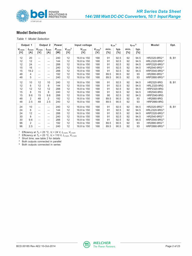
Model SelectionTable 1: Model Selection
Output 1 Output 2 Power Input voltage ηηηηη 24 1 ηηηηη110 2 Model Opt.Vo nom Io nom Vo nom Io nom Po nom Vi min 3 Vi cont Vi max3 min. typ. min. typ.
[V] [A] [V] [A] [W] [V] [V] [V] [%] [%] [%] [%]
12 20 -- -- 240 12 16.8 to 150 168 91 92.5 92 94.5 HR2320-9RG 4 B, B112 12 -- -- 144 12 16.8 to 150 168 91 92.5 92 94.5 HRL2320-9RG 4
12 24 -- -- 288 12 16.8 to 150 168 91 92.5 92 94.5 HRP2320-9RG 4
15 16 -- -- 240 12 16.8 to 150 168 91 92.5 92 94.5 HR2540-9RG 4
15 19.2 -- -- 288 12 16.8 to 150 168 91 92.5 92 94.5 HRP2540-9RG 4
48 4 -- -- 192 12 16.8 to 150 168 89.5 90.5 92 93 HR2880-9RG 4
48 5 -- -- 240 12 16.8 to 150 168 89.5 90.5 92 93 HRP2880-9RG 4
12 10 12 10 240 12 16.8 to 150 168 91 92.5 92 94.5 HR2320-9RG B, B112 6 12 6 144 12 16.8 to 150 168 91 92.5 92 94.5 HRL2320-9RG12 12 12 12 288 12 16.8 to 150 168 91 92.5 92 94.5 HRP2320-9RG15 8 15 8 240 12 16.8 to 150 168 91 92.5 92 94.5 HR2540-9RG15 9.6 15 9.6 288 12 16.8 to 150 168 90 92.5 92 94.5 HRP2540-9RG48 2 48 2 192 12 16.8 to 150 168 89.5 90.5 92 93 HR2880-9RG48 2.5 48 2.5 240 12 16.8 to 150 168 89.5 90.5 92 93 HRP2880-9RG
24 10 -- -- 240 12 16.8 to 150 168 91 92.5 92 94.5 HR2320-9RG 5 B, B124 6 -- -- 144 12 16.8 to 150 168 91 92.5 92 94.5 HRL2320-9RG 5
24 12 -- -- 288 12 16.8 to 150 168 91 92.5 92 94.5 HRP2320-9RG 5
30 8 -- -- 240 12 16.8 to 150 168 91 92.5 92 94.5 HR2540-9RG 5
30 9.6 -- -- 288 12 16.8 to 150 168 91 92.5 92 94.5 HRP2540-9RG 5
96 2 -- -- 192 12 16.8 to 150 168 89.5 90.5 92 93 HR2880-9RG 5
96 2.5 -- -- 240 12 16.8 to 150 168 89.5 90.5 92 93 HRP2880-9RG 5
1 Efficiency at TA = 25 °C, Vi = 24 V, Io nom, Vo nom2 Efficiency at TA = 25 °C, Vi = 110 V, Io nom, Vo nom3 Short time; see table 2 for details4 Both outputs connected in parallel5 Both outputs connected in series

BCD.00185 Rev AE2 10-Oct-2014 Page 3 of 23MELCHERThe Power Partners.
HR Series Data Sheet144/288 Watt DC-DC Converters, 10:1 Input Range
Product MarkingBasic type designation: applicable approval marks, CE mark,warnings, pin designation, patents and company logo,identification of LEDs.
Specific type designation: input voltage range, nominal outputvoltages and currents, degree of protection, batch no., serialno., and data code including production site, modificationstatus, and date of production.
Example: HR2540-9RB1G: DC-DC converter, operating input voltage range 16.8 – 150 VDC, 2 isolated outputs, eachproviding 15 V, 8 A, control input R to adjust the output voltages, cooling plate B1, and RoHS-compliant for all sixsubstances.
Part Number Description
Operating input voltage Vi cont (continuously):16.8 – 150 VDC ..................................... HR, HRL, HRP
Number of outputs ........................................................ 2, 72
Nominal voltage of main output Vo1 nom
12 V ............................................................................ 315 V ............................................................................ 524 V ............................................................................ 636 V ............................................................................ 748 V ............................................................................ 8Other voltages 1 ........................................................... 9
Nominal voltage of tracking output Vo2 3
12 V ............................................................................ 2015 V ............................................................................ 4024 V ............................................................................ 6036 V ............................................................................ 7048 V ............................................................................ 80Other specifications or additional features 1 ..... 21 – 99
Operational temperature range: TA:TA = –40 to 71 °C, TC ≤ 95 °C .................................... -9Other 1 ............................................................... -0, -5, -6
Auxiliary functions and options:Output voltage control input .........................................RCooling plate standard case ................................B, B1Cooling plate for long case 220 mm 2 .................... B2 2
RoHS-compliant for all 6 substances ...................... G 4
1 Customer-specific models. No safety-relevant changes compared to the respective basic model, e.g. different mechanicaldetails, special markings, mounted front plates, reduced output voltage, etc.
2 Converters with 220 mm case (customer-specific models). Add 5000 to the model number!3 The nominal voltages of both outputs are always equal.4 G is always placed at the end of the part number.Note: The sequence of options must follow the order above.
HR 2 5 40 -9 R B1 G
BCD.00185 Rev AE2 10-Oct-2014 Page 4 of 23MELCHERThe Power Partners.
HR Series Data Sheet144/288 Watt DC-DC Converters, 10:1 Input Range
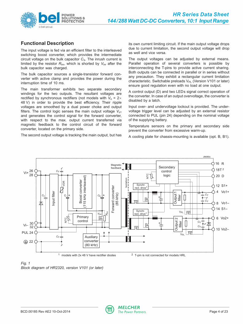
Functional DescriptionThe input voltage is fed via an efficient filter to the interleavedswitching boost converter, which provides the intermediatecircuit voltage on the bulk capacitor Cb. The inrush current islimited by the resistor Rinr, which is shorted by Vinr after thebulk capacitor was charged.
The bulk capacitor sources a single-transistor forward con-verter with active clamp and provides the power during theinterruption time of 10 ms.
The main transformer exhibits two separate secondarywindings for the two outputs. The resultant voltages arerectified by synchronous rectifiers (not models with Vo = 2×48 V) in order to provide the best efficiency. Their ripplevoltages are smoothed by a dual power choke and outputfilters. The control logic senses the main output voltage Vo1and generates the control signal for the forward converter,with respect to the max. output current transferred viamagnetic feedback to the control circuit of the forwardconverter, located on the primary side.
The second output voltage is tracking the main output, but has
Fig. 1Block diagram of HR2320, version V101 (or later)
its own current limiting circuit. If the main output voltage dropsdue to current limitation, the second output voltage will dropas well and vice versa.
The output voltages can be adjusted by external means.Parallel operation of several converters is possible byinterconnecting the T-pins to provide active current sharing.Both outputs can be connected in parallel or in series withoutany precaution. They exhibit a rectangular current limitationcharacteristic. Switchable preloads VPL (Version V101 or later)ensure good regulation even with no load at one output.
A control output (D) and two LEDs signal correct operation ofthe converter. In case of an output overvoltage, the converter isdisabled by a latch.
Input over- and undervoltage lockout is provided. The under-voltage trigger level can be adjusted by an external resistorconnected to PUL (pin 24) depending on the nominal voltageof the supplying battery.
Temperature sensors on the primary and secondary sideprevent the converter from excessive warm-up.
A cooling plate for chassis-mounting is available (opt. B, B1).
26
28
3032
JM080c
R
T 2
D
Vo1+
Vo1–
Vo2+
Vo2–
CY
Inp
ut
filte
r
CY
Bo
ost
co
nve
rte
r
(11
5 k
Hz in
terle
ave
d)
+Cb
Vi+
Vi–
22
PUL 24
+Ci
Auxiliary
converter
(80 kHz)
Fo
rwa
rd c
on
ve
rte
r
(85
kH
z)
Iso
lati
on
Synchr.rect. drive1
Magneticfeedback
16
18
20
Secondary
control
logicO
utp
ut 1
filte
r
S1+
S1–
CY
CY
CY+
+
4
6
8
10
12
14
Primary
control
NT
C
NT
C
Cx
VD
R
Rin
r
Vinr
Ou
tpu
t 2
filte
r
CY
Synchr.rect. drive1
1 models with 2x 48 V have rectifier diodes 2 T-pin is not connected for models HRL
VPL
VPL

BCD.00185 Rev AE2 10-Oct-2014 Page 5 of 23MELCHERThe Power Partners.
HR Series Data Sheet144/288 Watt DC-DC Converters, 10:1 Input Range
Electrical Input DataGeneral Conditions:
– TA = 25 °C, unless TC is specified.– Pin 24 (PUL) left open-circuit– Pin 16 (R) and 18 (D) left open-circuit.
Table 2: Input data
Model HR HRL HRP Unit
Characteristics Conditions min typ max min typ max min typ max
V i Operating input voltage Io = 0 – Io max 16.8 150 16.8 150 16.8 150 V
for ≤2 s, without shutdown TC min – TC max 12.0 168 12.0 168 12.0 168
V i nom Nom. input voltage range 24 (110) 120 24 (110) 120 24 (110) 120
V i abs Input voltage limits 3 s, without damage 0 176 0 176 0 176
Ii Input current: HR2320 Vi max .. (110 V) .. Vi min, Io nom 1.76 (2.36) 15.65 1.03 (1.38) 9.31 2.1 (2.83) 21.4 AHR2540 1.76 (2.36) 15.65 2.1 (2.83) 21.4HR2880 1.37 (1.86) 12.82 1.71 (2.33) 16.05
P i 0 No-load input power Vi min – Vi max, Io = 0 11 11 11 W
P i inh Idle input power Vi min – Vi max, VPUL = 0 V 2.5 2.5 2.5
Cx Input capacitance 1 8.6 8.6 8.6 µF
R i Input resistance 10 10 10 mΩ
I inr p Peak inrush current 2 Vi = 150 V, Io nom 30 30 30 A
t inr r Time constant of I inr 10 10 10 ms
td on Start-up time 0 →Vi min, Io nom 400 400 400
tr Rise time after shutdown Vi ≥16.8 V, Io nom, VPUL = 0 → 5 V 40 40 40
1 At start-up (not smoothed by the inrush current limiter)2 According to ETS 300132-2
PUL Function and FuseThis converter is designed for an extremly wide input voltagerange, allowing for connection to all common railwaybatteries. However, the programmable input undervoltagelockout (PUL, pin 24) should be adjusted adequately in orderto limit the high input current at start-up; see fig 2.
Table 3 specifies the values of the resistor R PUL, connectedbetween PUL and Vi–, versus the resultant minimum inputvoltage and the recommended fuse.
Fig. 3 shows more values of R PUL versus start-up voltage. Forstationary batteries, a higher start-up voltage might beadvatageous.
Note: If PUL (pin 24) is connected to Vi– (pin 30/32), the converteris disabled; see Shutdown Function.
No fuse is incorporated in the converter. Consequently, anexternal fuse or a circuit breaker must be installed at systemlevel to protect against severe defects.
Reverse polarity protection is provided by an antiparalleldiode across the input, causing the external input fuse orcircuit breaker to trip.
Fig. 2Typ. input current versus input voltage at nominal load(HR2320)
25
20
15
10
020 40 100 120
5
60 80 140 160
Ii [A]
0
JM087
Vi [V]

BCD.00185 Rev AE2 10-Oct-2014 Page 6 of 23MELCHERThe Power Partners.
HR Series Data Sheet144/288 Watt DC-DC Converters, 10:1 Input Range
Fig. 4Equivalent input ciruit
Fig. 5Inrush current at Vi = 150 V, Io nom (HR2320)
0.1 100 200 300 400 ms
30
Iinr [A]
0
JM08650
40
10
20
Input Transient ProtectionThe double stage symmetrical input filter together with a VDR(voltage depending resistor) form an effective protectionagainst high input transient voltages which typically occur inbattery-driven mobile applications.
At very high input voltage, the overvoltage lockout disables theconverter such protecting it from damage.
Inrush Current LimitationThe converters exhibit an electronic inrush current limitingcircuit. This circuit is also functional, when the input voltage isremoved and immediately reapplied.
However, several capacitors are directly connected to theinput pins. Consequently, a peak curent is still present whenapplying the input voltage.
The inrush current peak value can be determined by followingcalculation; see also fig. 4:
Vi sourceIinr p = ––––––––– (R ext + Ri )
Fig. 3RPUL versus switch-on voltage
Table 3: PUL Specification (typ.) and recommended externalfuse for all models. Smaller fuses are possible for HRL models.
Battery RPUL Vi min (on / off) Fuse rating
24 V ∞ 15 V 12 V 3 25 A, fast, Littlefuse 314 1
36 V 16.9 kΩ 20 V 18 V 16 A, fast, Schurter /SP 248 V 13.7 kΩ 26 V 20 V 12.5 A, fast, Schurter /SP 272 V 9.5 kΩ 38 V 32 V 8 A, fast, Schurter /SP 2110 V 5.2 kΩ 62 V 57 V 6.3 A, slow, BEL fuse MRT 2120 V 2.9 kΩ 90 V 84 V 5 A, slow, BEL fuse MRT 2
all < 100 Ω Converter disabled1 fuse size 6.3 × 32 mm 2 fuse size 5 × 20 mm 3 for ≤ 2 s
Fig. 6Efficiency versus Vi and Io (HR2320, both outputs connectedin series)
60
70
80
90
0.4 0.8 Io / Io nom0
JM100100
η [%]
0.60.2
Vi = 15.4 V
Vi = 150 V
Vi = 110 V
Efficiency
80
60
40
02 4 10 12
20
6 8 14
Vi min [V]
RPUL
JM101a
16 kΩ
CX
Rext RiIinr p
Vi source
+
JM085a
+
Vo+
Vo–
Load
Vi+
Vi–

BCD.00185 Rev AE2 10-Oct-2014 Page 7 of 23MELCHERThe Power Partners.
HR Series Data Sheet144/288 Watt DC-DC Converters, 10:1 Input Range
Electrical Output DataGeneral Conditions: – TA = 25 °C, unless TC is specified; Pin 24 (PUL) ≥ 5 V
Table 4a: Output data of HR2320 and HRL2320
Model HR2320 HRL2320 UnitNom. output voltage 2 ××××× 12 V 2 ××××× 12 V
Output 1 Output 2 Output 1 Output 2
Characteristics Conditions min typ max min typ max min typ max min typ max
Vo Output voltage Vi nom, 0.5 I o nom 11.93 12.0 12.07 12.0 1.93 12.0 12.07 12.0 V
Vo BR Output protection Output 2 -- 14.4 15.9 -- 14.4 15.9(suppressor diode)
Io nom Output current nom. Vi min – Vi max 10 10 6.0 6.0 A
Io1L, Io2L Output current limit1 TC min – TC max 10.5 10.5 6.5 6.5
Io12L Output current limit1 2 212 -- 13 --
vo Output noise incl. Vi nom, I o nom 60 60 60 60 mVppspikes BW = 20 MHz
Vo adj Adjustment by R-input 4 Vi min – Vi max 4.8 13.8 1 3 4.8 13.8 1 3 V
∆Vo u Static line/load regulation (0.1 – 1) Io nom ±120 3 ±120 3 mV(total deviation of Vo)
vo d Dynamic Voltage Vi nom, 0.5 I o2 nom ±200 ±200 ±150 ±150load deviation 5 Io1 nom ↔ 0.5 Io1 nom
to d regulat. Recovery time 5 and after turn on 1 3 1 3 ms
αvo Temperature coefficient TC min – TC max +0.01 +0.02 -- +0.01 +0.02 -- %/Kof output voltage Io nom
Table 4b: Output data of HRP2320 models
Model HRP2320 UnitNom. output voltage 2 ××××× 12 V
Output 1 Output 2
Characteristics Conditions min typ max min typ max
Vo Output voltage Vi nom, 0.5 I o nom 11.93 12.0 12.07 12.0 V
Vo BR Output protection Output 2 -- 14.4 15.9(suppressor diode)
Io nom Output current nom. Vi min – Vi max 12 12 A
Io1L, Io2L Output current limit1 TC min – TC max 12.3 12.3
Io12L Output current limit1 2 24.6 2 --
vo Output noise incl. Vi nom, I o nom 60 60 mVpp spikes BW = 20 MHz
Vo adj Adjustment by R-input 4 Vi min – Vi max 4.8 13.8 1 3 V
∆Vo u Static line/load regulation (0.1 – 1) Io nom ±120 3 mV(total deviation of Vo)
vo d Dynamic Voltage Vi nom, 0.5 I o2 nom ±250 ±250load deviation 5 Io1 nom ↔ 0.5 Io1 nom
to d regulat. Recovery time 5 and after turn on 1 3 ms
αvo Temperature coefficient TC min – TC max +0.01 +0.02 -- %/Kof output voltage Io nom
1 If Vo is increased above Vo nom through R-, sense, or T-input, the output currents should be reduced so that Po nom is not exceeded.2 Both outputs connected in parallel3 See Output voltage regulation4 For battery charger application, a defined negative temp. coefficient can be provided by using a temp. sensor (see Accessories)5 See Dynamic load regulation6 Measured with a ceramic cap of 1 µF across each output.

BCD.00185 Rev AE2 10-Oct-2014 Page 8 of 23MELCHERThe Power Partners.
HR Series Data Sheet144/288 Watt DC-DC Converters, 10:1 Input Range
Table 4c: Output data of HR2540 and HRP2540. General conditions as per table 6a
Model HR2540 HRP2540 UnitNom. output voltage 2 ××××× 15 V 2 ××××× 15 V
Output 1 Output 2 Output 1 Output 2
Characteristics Conditions min typ max min typ max min typ max min typ max
Vo Output voltage Vi nom, 0.5 I o nom 14.91 15.0 15.09 15.0 14.91 15.0 15.09 15.0 V
Vo BR Output protection Output 2 -- 20.9 23.1 -- 20.9 23.1(suppressor diode)
Io nom Output current nom. Vi min – Vi max 8 8 9.6 9.6 A
Io1L, Io2L Output current limit1 TC min – TC max 8.4 8.4 10.1 10.1
Io12L Output current limit1 2 16.8 2 -- 19.7 2 --
vo Output noise incl. Vi nom, Io nom 75 75 75 75 mVppspikes BW = 20 MHz
Vo adj Adjustment by R-input 4 Vi min – Vi max 6.0 17.25 1 3 6.0 17.25 1 3 V
∆Vo u Static line/load regulation (0.1 – 1) Io nom ±150 3 ±150 3 mV(total deviation of Vo)
vo d Dynamic Voltage Vi nom, 0.5 Io2 nom ±250 ±250 ±300 ±300load deviation 5 Io1 nom ↔ 0.5 Io1 nom
to d regulat. Recovery time 5 and after turn on 1 3 1 3 ms
αvo Temperature coefficient TC min – TC max +0.01 +0.02 -- +0.01 +0.02 -- %/Kof output voltage Io nom
1 If the output voltages are increased above Vo nom through R-input control, remote sensing, or option T, the output currents should bereduced accordingly so that Po nom is not exceeded.
2 Both outputs connected in parallel3 See Output voltage regulation4 For battery charger applications, a defined negative temperature coefficient can be provided by using a temperature sensor (see
Accessories)5 See Dynamic load regulation6 Measured with a ceramic cap of 1 µF across each output.
BCD.00185 Rev AE2 10-Oct-2014 Page 9 of 23MELCHERThe Power Partners.
HR Series Data Sheet144/288 Watt DC-DC Converters, 10:1 Input Range
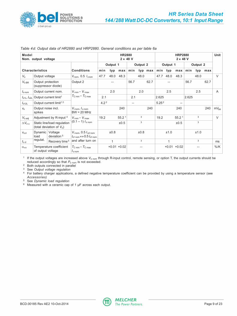
Table 4d: Output data of HR2880 and HRP2880. General conditions as per table 6a
Model HR2880 HRP2880 UnitNom. output voltage 2 ××××× 48 V 2 ××××× 48 V
Output 1 Output 2 Output 1 Output 2
Characteristics Conditions min typ max min typ max min typ max min typ max
Vo Output voltage Vi nom, 0.5 I o nom 47.7 48.0 48.3 48.0 47.7 48.0 48.3 48.0 V
Vo BR Output protection Output 2 -- 56.7 62.7 -- 56.7 62.7(suppressor diode)
Io nom Output current nom. Vi min – Vi max 2.0 2.0 2.5 2.5 A
Io1L, Io2L Output current limit1 TC min – TC max 2.1 2.1 2.625 2.625
Io12L Output current limit1 2 4.2 2 -- 5.25 2 --
vo Output noise incl. Vi nom, Io nom 240 240 240 240 mVppspikes BW = 20 MHz
Vo adj Adjustment by R-input 4 Vi min – Vi max 19.2 55.2 1 3 19.2 55.2 1 3 V
∆Vo u Static line/load regulation (0.1 – 1) Io nom ±0.5 3 ±0.5 3
(total deviation of Vo)
vo d Dynamic Voltage Vi nom, 0.5 I o2 nom ±0.8 ±0.8 ±1.0 ±1.0load deviation 5 Io1 nom ↔ 0.5 Io1 nom
to dregulat. Recovery time 5 and after turn on 1 3 1 3 ms
αvo Temperature coefficient TC min – TC max +0.01 +0.02 -- +0.01 +0.02 -- %/Kof output voltage Io nom
1 If the output voltages are increased above Vo nom through R-input control, remote sensing, or option T, the output currents should bereduced accordingly so that Po nom is not exceeded.
2 Both outputs connected in parallel3 See Output voltage regulation4 For battery charger applications, a defined negative temperature coefficient can be provided by using a temperature sensor (see
Accessories)5 See Dynamic load regulation6 Measured with a ceramic cap of 1 µF across each output.
BCD.00185 Rev AE2 10-Oct-2014 Page 10 of 23MELCHERThe Power Partners.
HR Series Data Sheet144/288 Watt DC-DC Converters, 10:1 Input Range
Thermal ConsiderationsIf a converter is located in free, quasi-stationary air (con-vection cooling) at the indicated maximum ambienttemperature TA max (see table Temperature specifications) andis operated within the specified input voltage range andnominal load, the temperature measured at the Measuringpoint of case temperature TC (see Mechanical Data) willapproach the indicated value TC max after the warm-up phase.However, the relationship between TA and TC depends heavilyupon the conditions of operation and integration into asystem. The thermal conditions are influenced by inputvoltage, output current, airflow, and temperature ofsurrounding components and surfaces. TA max is therefore,contrary to TC max, an indicative value only.
Caution: The installer must ensure that under all operatingconditions TC remains within the limits stated in the tableTemperature specifications.
Notes: Sufficient forced cooling or enhanced cooling with thehelp of cooling plates (options B, B1) allows for TA to be higherthan 71 °C (e.g. 85 °C), as long as TC max is not exceeded.
Thermal ProtectionTwo temperature sensors generate an internal inhibit signal,which disables the converter in the case of overtemperature.The outputs automatically recover when the temperaturedrops below the limit.
Interruption TimeThe integrated storage capacitor (Cb) is loaded to the boostvoltage and ensures full output voltage with nominal loadduring an interruption time (or ride-through time) of at least 10ms, provided that Vi was ≥ 20 V before the interruption. Thiscomplies with EN 50155 class S2.
Output ProtectionThe 2nd output of xx2320 models is protected by a suppressordiode against overvoltage, which could occur due to a failureof the internal control circuit. This suppressor diode was notdesigned to withstand externally applied overvoltages.Overload at any of the outputs will cause both outputs to shut-down.
Note: Vo BR of the suppressor diode is specified in ElectricalOutput Data. If this voltage is exceeded, the suppressor diodegenerates losses and may become a short circuit.
Note: The output voltage of the first output is monitored. If itexceeds typ. 140% of Vo nom for 10 ms, the converter is in-hibited. To reactivate, Vi must be removed or a shutdown signalapplied to PUL (pin 24).
Each output has its own current limiting circuit, providing arectangular output characterisitc and protecting against shortcircuit. There is no limitation for the capacitive load, andbattery charging is possible as well.
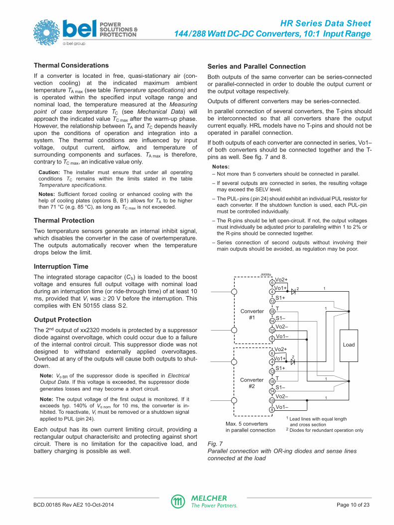
Series and Parallel ConnectionBoth outputs of the same converter can be series-connectedor parallel-connected in order to double the output current orthe output voltage respectively.
Outputs of different converters may be series-connected.
In parallel connection of several converters, the T-pins shouldbe interconnected so that all converters share the outputcurrent equally. HRL models have no T-pins and should not beoperated in parallel connection.
If both outputs of each converter are connected in series, Vo1–of both converters should be connected together and the T-pins as well. See fig. 7 and 8.
Notes:– Not more than 5 converters should be connected in parallel.
– If several outputs are connected in series, the resulting voltagemay exceed the SELV level.
– The PUL- pins (pin 24) should exhibit an individual PUL resistor foreach converter. If the shutdown function is used, each PUL-pinmust be controlled induvidually.
– The R-pins should be left open-circuit. If not, the output voltagesmust individually be adjusted prior to paralleling within 1 to 2% orthe R-pins should be connected together.
– Series connection of second outputs without involving theirmain outputs should be avoided, as regulation may be poor.
Fig. 7Parallel connection with OR-ing diodes and sense linesconnected at the load
Load
1
1
1
2
2
S1+
Vo1+
Vo2–
S1–
T
S1+
Vo2+
Vo2–
S1–
T
1
Max. 5 converters
in parallel connection
JM088a
Converter
#1
Converter
#2
Vo1–
Vo2+
Vo1+
Vo1–
1 Lead lines with equal length
and cross section2 Diodes for redundant operation only
6
4
12
18
14
10
8
6
8
10
14
18
12
4
BCD.00185 Rev AE2 10-Oct-2014 Page 11 of 23MELCHERThe Power Partners.
HR Series Data Sheet144/288 Watt DC-DC Converters, 10:1 Input Range
Vo/Vo nom
0.98
0.5
00.5 1.0
Io1
IoL
Io/Io nom
05098a
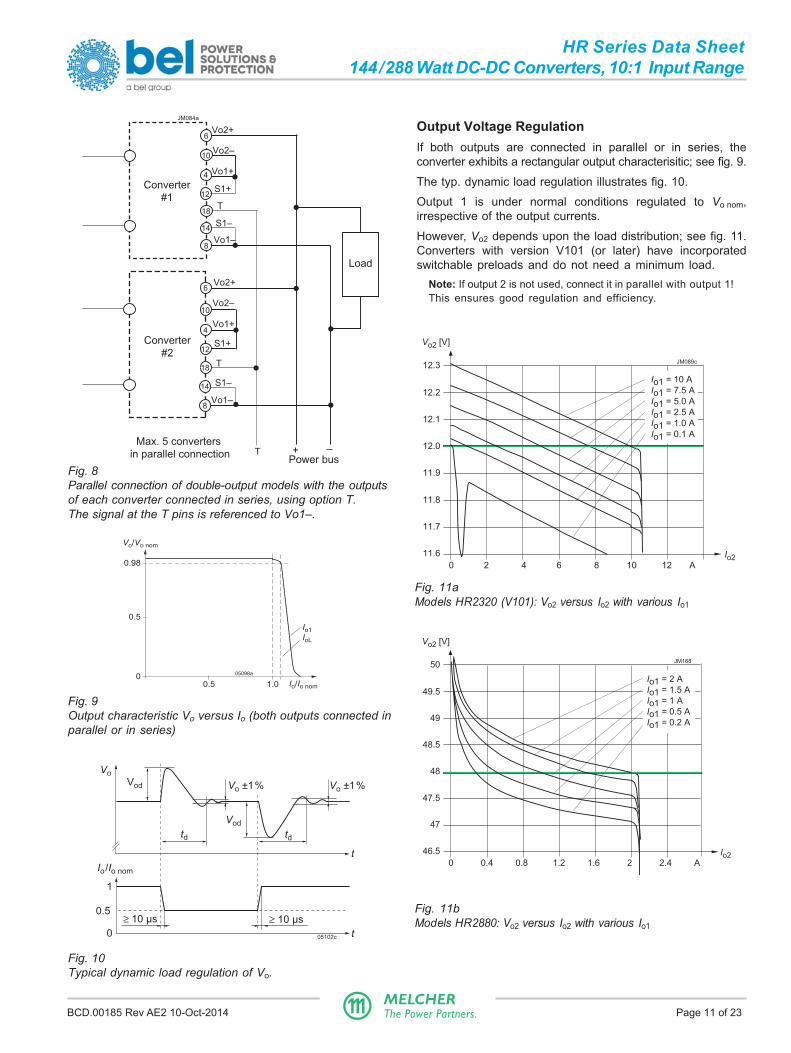
Fig. 11aModels HR2320 (V101): Vo2 versus Io2 with various Io1
Fig. 8Parallel connection of double-output models with the outputsof each converter connected in series, using option T.The signal at the T pins is referenced to Vo1–.
Fig. 9Output characteristic Vo versus Io (both outputs connected inparallel or in series)
Fig. 10Typical dynamic load regulation of Vo.
Vod
Vod
td td
Vo ±1% Vo ±1%
t
t
≥ 10 µs ≥ 10 µs
Vo
0
0.5
1
Io/Io nom
05102c
Load
Max. 5 converters
in parallel connection + –Power bus
Converter
#1
Vo2–
Vo2+
Vo1–
Vo1+
T
Converter
#2
Vo2–
Vo2+
Vo1–
Vo1+
T
JM084a
8
18
18
4
6
10
10
6
S1+
4
12
S1–14
12S1+
S1–14
8
T
Output Voltage RegulationIf both outputs are connected in parallel or in series, theconverter exhibits a rectangular output characterisitic; see fig. 9.
The typ. dynamic load regulation illustrates fig. 10.
Output 1 is under normal conditions regulated to Vo nom,irrespective of the output currents.
However, Vo2 depends upon the load distribution; see fig. 11.Converters with version V101 (or later) have incorporatedswitchable preloads and do not need a minimum load.
Note: If output 2 is not used, connect it in parallel with output 1!This ensures good regulation and efficiency.
0 2 4 6 8 10 12 A
Io211.6
11.7
11.8
11.9
12.0
12.1
12.2
12.3
Vo2 [V]
JM089c
Io1 = 10 A
Io1 = 7.5 A
Io1 = 5.0 A
Io1 = 2.5 A
Io1 = 1.0 A
Io1 = 0.1 A
Fig. 11bModels HR2880: Vo2 versus Io2 with various Io1
0 0.4 0.8 1.2 1.6 2 2.4 A
Io246.5
47
47.5
48
48.5
49
49.5
50
Vo2 [V]
JM168
Io1 = 2 A
Io1 = 1.5 A
Io1 = 1 A
Io1 = 0.5 A
Io1 = 0.2 A

BCD.00185 Rev AE2 10-Oct-2014 Page 12 of 23MELCHERThe Power Partners.
HR Series Data Sheet144/288 Watt DC-DC Converters, 10:1 Input Range
Auxiliary FunctionsShutdown FunctionThe PUL input (pin 24) can also be used as shutdown (for thePUL function see table 3). The response time tr is specified intable 2.
Fig. 12Typical output response to the PUL-signal (shutdown)
The current coming out from pin 24 (PUL) is typ. 1.5 mA (<2mA). If pin 24 is left open-circuit, the voltage is typ. 5 V. Theconverter is disabled when VPUL is ≤ 500 mV.
Table 5: Maximum voltage compensation allowed usingsense lines
Output Total voltage difference Voltage difference voltage between sense lines and between
their respective outputs Vo1– and S1–
12 V <1.0 V <0.5 V
15 V <1.25 V <0.6 V
48 V <2.0 V <1.0 V
Current Share FunctionIf the pins 18 (T) of parallel-connected converters are linkedtogether, the converters share the output current evenly. Referto section Parallel and Series Connection. Not for HRLmodels.
Sense LinesThis feature allows for compensation of voltage drops acrossthe connector contacts and if necessary, across the load lines.We recommend connecting the sense lines directly at thefemale connector.
To ensure correct operation, both sense lines (S1+, S1–)should be connected to their respective power outputs (Vo1+and Vo1–), and the voltage difference between any sense lineand its respective power output (as measured on theconnector) should not exceed the values specified in table 7.
Important: Sense lines should be connected! Incorrectly con-nected sense lines may activate the overvoltage protectionresulting in a permanent short-circuit of the output. Open sense
Fig. 13Circuit for the shutdown function
lines are allowed, but result in inaccurate output voltages.
Output Voltage AdjustAs a standard feature, the converters offer an adjustableoutput voltage. The control input R (pin 16) accepts either acontrol voltage Vext or a resistor Rext to adjust the outputvoltage. When input R is not connected, the output voltage isset to Vo nom.
a) Adjustment by means of an external control voltage Vextbetween pin 16 (R) and pin 14 (S1–):
The control voltage range is 1.0 – 2.875 V and allows for anadjustment in the range of approx. 40 – 115% of Vo nom.
Vo • 2.5 VVext ≈ –––––––– Vo nom
Caution: Applying an external control voltage >2.875 V maydamage the converter.
b) Adjustment by means of an external resistor:Depending on the value of the required output voltage, theresistor shall be connected
either: between pin 16 (R) and pin 14 (S1–) to adjust theoutput voltage in the range of approx. 40 – 100% of Vo nom.
VoRext1 ≈ 4 kΩ • ––––––––– Vo nom – Vo
or: between pin 16 (R) and pin 12 (S1+) to adjust the outputvoltage in the range of 100 – 115% of Vo nom.
(Vo – 2.5 V)Rext2 ≈ 4 kΩ • –––––––––––––––––– 2.5 V • (Vo/Vo nom – 1)
0 t
t0
PUL
1
0.1
1
Vo/Vo nom
tr tf
JM139
PUL
Vi–
Vi+
IPUL
28
24
22
JM127
Outp
ut
VP
UL
32
PE
30
RP
UL
Fig. 14Output voltage adjustment
R
S1+
S1–
+
Vext
–
4 kΩVref = 2.5 V
Control
logic Rext1
Rext2
JM091a
Vi–
Vi+
+
12
16
14

BCD.00185 Rev AE2 10-Oct-2014 Page 13 of 23MELCHERThe Power Partners.
HR Series Data Sheet144/288 Watt DC-DC Converters, 10:1 Input Range
2.10
2.15
2.20
2.25
2.30
2.35
2.40
2.45Cell voltage [V]
–20 –10 0 10 20 30 40 50 °C
06139b
VC = 2.27 V, –3 mV/K VC = 2.27 V, –3.5 mV/KVC = 2.23 V, –3 mV/K VC = 2.23 V, –3.5 mV/K
Vo safe
Fig. 17Trickle charge voltage versus temperature for definedtemperature coefficient. Vo nom is the output voltage with openR-input.
Fig. 16Connection of a temperature sensor
Power
supplyLoad
–+
Input Vo–
R
Temperature sensor
ϑ
03099d
Battery
Vo+
+
Caution: To prevent the converter from damage, the value of R 'extshall never be less than the value for increasing Vo1 to 115% !
Notes:– If the output voltages are increased above Vo nom via R-input
control, sense lines, or option T, the output currents should bereduced, so that Po nom is not exceeded.
– The second output of double-output models follows the voltageof the controlled main output.
Output Voltage MonitorThe output voltage monitor generates a logic "low" signal(NPN open-collector output) at the D-output (pin 20), when Vo1≥ 0.96 Vo nom. For converters with version V101 (or later), thevoltage at S1+ (corresponding to Vo1) must be ≥ 0.96 Vo nomand ≤ 1.04 Vo nom (typ. values). Then, a green LED (Out OK) atthe frontplate is illuminated. If the output voltage is adjusted bythe R-input, the trigger levels are corrected accordingly.
At low D-output, the current is limited by a 10 Ω protectiveresistor; for converters with Version V102 (or later) ID shouldbe ≤ 100 mA. If the D-output is high (open collector), VD should
Fig. 15Output voltage monitor
S1+
S1–
DID
Rp
Input
JM090
NPN open
collector 20
14
10 Ω
12
VD
be ≤ 75 V. For previous converters: ≤ 50 mA and 50 V.Note: Output overvoltage activates a latch; see Output Protection.
IndicatorsTwo green indicators are visible at the front plate:
- Out OK; see Output Voltage Monitor- In OK. This signal is activated when Vi is below 158 V and
greater than Vi min, whereas Vi min is defined by the adjustresistor connected to the PUL input (pin 24).
Battery Charging /Temperature SensorAll converters with an R-input are suitable for battery chargerapplication. For optimal battery charging and life expectancyof the battery an external temperature sensor can be con-nected to the R-input. The sensor is mounted as close aspossible to the battery and adjusts the output voltage accoringto the battery temperature.
Depending upon cell voltage and the temperature coefficientof the battery, different sensor types are available, seeAccessories.

BCD.00185 Rev AE2 10-Oct-2014 Page 14 of 23MELCHERThe Power Partners.
HR Series Data Sheet144/288 Watt DC-DC Converters, 10:1 Input Range
Electromagnetic Compatibility (EMC)A metal oxide VDR together and an efficient input filter form aneffective protection against high input transient voltages,
which typically occur in most installations. The convertershave been successfully tested to the following specifications:
Table 6: Electromagnetic immunity (type tests)
Phenomenon Standard Level Coupling Value Waveform Source Test In Perf.mode 1 applied imped. procedure oper. crit.2
Electrostatic IEC/EN 4 5 contact discharge 8000 Vp 1/50 ns 330 Ω 10 positive and yes Adischarge 61000-4-2 air discharge 15000 Vp
10 negative(to case) discharges
Electromagnetic IEC/EN x 6 antenna 20 V/m AM 80% /1 kHz n.a. 80 – 1000 MHz yes Afield 61000-4-3 7 antenna 20 V/m AM 80% /1 kHz n.a. 800 – 1000 MHz yes A
10 V/m 1400 – 2100 MHz
5 V/m 2100 – 2500 MHz
3 antenna 10 V/m 50% duty cycle, n.a. 900 ±5 MHz yes A200 Hz rep. rate
Electrical fast IEC/EN 3 8 capacitive, o/c ±2000 Vp bursts of 5/50 ns 50 Ω 60 s positive yes Atransients/burst 61000-4-4 4 i/c, +i/–i ±4000 Vp
2.5/5 kHz over 60 s negative
direct 15 ms; burst transients perperiod: 300 ms coupling mode
Surges IEC/EN 3 9 i/c ±2000 Vp 1.2/50 µs 12 Ω 5 pos. and 5 neg. yes A61000-4-5 +i/–i ±1000 Vp 2 Ω surges per
coupling mode
Conducted IEC/EN 310 i, o, signal wires 10 VAC AM 80% 150 Ω 0.15 – 80 MHz yes Adisturbances 61000-4-6 (140 dBµV) 1 kHz
Power frequency IEC/EN 311 -- 300 A/m 60 s in all 3 axis yes Amagnetic field 61000-4-8
Pulse IEC/EN - -- ±300 A/m 5 pulses per axis yes Amagnetic field 61000-4-9 repetit. rate 10 s
1 i = input, o = output, c = case2 A = normal operation, no deviation from specs.; B = normal operation, temporary loss of function or deviation from specs possible5 Exceeds EN 50121-3-2:2006 table 9.3 and EN 50121-4:2006 table 1.4.6 Corresponds to EN 50121-3-2:2006 table 9.1 and exceeds EN 50121-4:2006 table 1.1.7 Corresponds to EN 50121-3-2:2006 table 9.2 and EN 50121-4:2006 table 1.2 (compliance with digital mobile phones).8 Corresponds to EN 50121-3-2:2006 table 7.2 and EN 50121-4:2006 table 2.2.9 Covers or exceeds EN 50121-3-2:2006 table 7.3 and EN 50121-4:2006 table 2.3.10 Corresponds to EN 50121-3-2:2006 table 7.1 and EN 50121-4:2006 table 3.1 (radio frequency common mode).11 Corresponds to EN 50121-4:2006 table 1.3.
Electromagnetic Immunity
BCD.00185 Rev AE2 10-Oct-2014 Page 15 of 23MELCHERThe Power Partners.
HR Series Data Sheet144/288 Watt DC-DC Converters, 10:1 Input Range
0
dBµV
20
40
60
80
0.2 0.5 1 2 5 10 20 MHz
JM107
VUS EMC Labatory, Vin = 110 VDC, Iout = 2x 10 A, C115. Testdistance 10 m, Class A, HR2320-9RG, B01932739, U00004, 26.07.2012
EN 55011 A qp
EN 55011 A av
0
dBµV
20
40
60
80
0.2 0.5 1 2 5 10 20 MHz
JM106
VUS EMC Labatory, Vin = 24 VDC, Iout = 2x 10 A, C115. Testdistance 10 m, Class A, HR2320-9RG, B01932739, U00004, 26.07.2012
EN 55011 A qp
EN 55011 A av
30 50 100 200 500 1000 MHz
dBµV/m
10
20
30
40
0
60
EN 55011 A
VUS EMC Labatory, Vin=24VDC, Iout=2x10A, C115. Testdistance 10 m, Class A, HR2320-9RG, B01932739, U00004, 26.07.2012
JM108
50 EN 55011 A
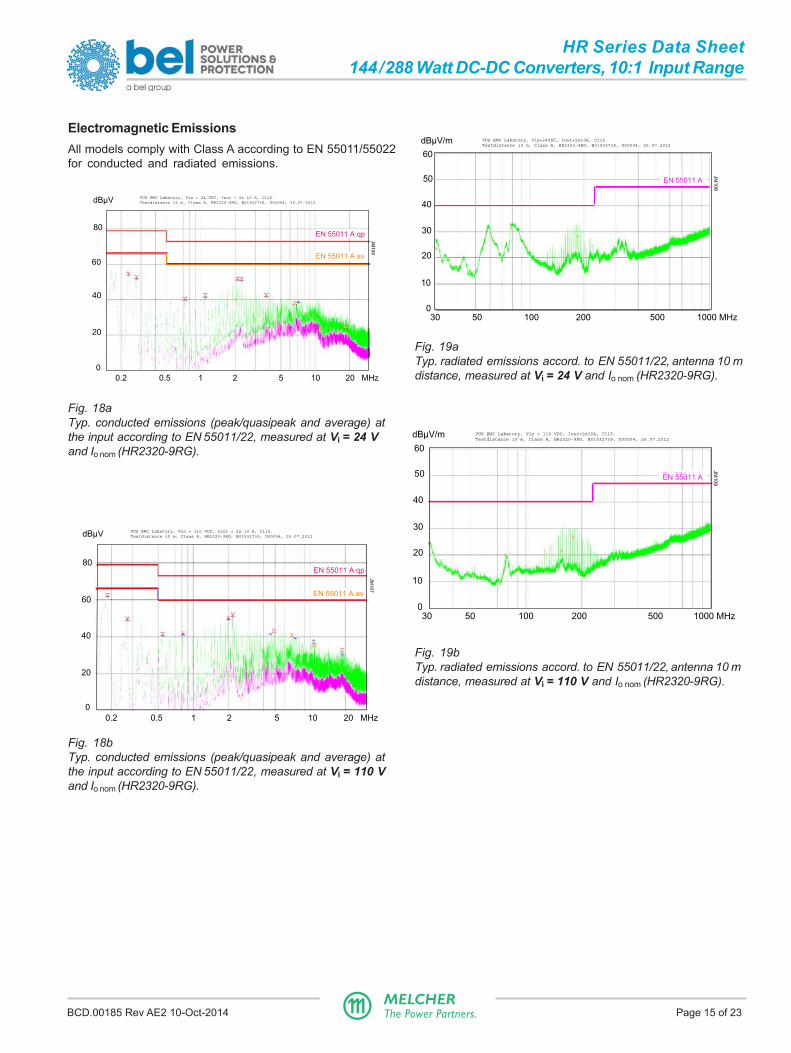
Fig. 18aTyp. conducted emissions (peak/quasipeak and average) atthe input according to EN 55011/22, measured at Vi = 24 Vand Io nom (HR2320-9RG).
Fig. 19aTyp. radiated emissions accord. to EN 55011/22, antenna 10 mdistance, measured at Vi = 24 V and Io nom (HR2320-9RG).
Fig. 19bTyp. radiated emissions accord. to EN 55011/22, antenna 10 mdistance, measured at Vi = 110 V and Io nom (HR2320-9RG).
30 50 100 200 500 1000 MHz
dBµV/m
10
20
30
40
0
60
EN 55011 A
VUS EMC Labatory, Vin = 110 VDC, Iout=2x10A, C115. Testdistance 10 m, Class A, HR2320-9RG, B01932739, U00004, 26.07.2012
JM109
50 EN 55011 AEN 55011 A
Fig. 18bTyp. conducted emissions (peak/quasipeak and average) atthe input according to EN 55011/22, measured at Vi = 110 Vand Io nom (HR2320-9RG).
Electromagnetic EmissionsAll models comply with Class A according to EN 55011/55022for conducted and radiated emissions.

BCD.00185 Rev AE2 10-Oct-2014 Page 16 of 23MELCHERThe Power Partners.
HR Series Data Sheet144/288 Watt DC-DC Converters, 10:1 Input Range
Immunity to Environmental ConditionsTable 7: Mechanical and climatic stress (type tests)
Test method Standard Test conditions Status
Cb Humidity IEC/EN 60068-2-56 Temperature: 25 °C ConverterRelative humidity: 95 % operatingDuration: 8 h
Cab Damp heat IEC/EN 60068-2-78 Temperature: 40 ±2 °C Convertersteady state MIL-STD-810D section 507.2 Relative humidity: 93 +2/-3 % not
Duration: 56 days operating
Db Damp heat test, EN 50155:2007, clause 12.2.5 Temperature: 55 °C and 25 °C Convertercyclic IEC/EN 60068-2-30 Cycles (respiration effect): 2 not
Duration: 2× 24 h operating
Bd Dry heat test EN 50155:2007, clause 12.2.4 Temperature: 70 °C Convertersteady state IEC/EN 60068-2-2 Duration: 6 h operating
Ad Cooling test EN 50155:2007, clause 12.2.3 Temperature, duration –40 °C, 2 h Conv. notsteady state IEC/EN 60068-2-1 Performance test +25 °C operating
-- Salt mist test EN 50155:2007, clause 12.2.10 Temperature: 35±2 °C Convertersodium chloride class ST3 Duration: 48 h not(NaCl) solution operating
Fc Vibration IEC/EN 60068-2-6 Acceleration amplitude: 0.35 mm (10 – 60 Hz) Converter(sinusoidal) MIL-STD-810D section 514.3 5 gn = 49 m/s2 (60 - 2000 Hz) operating
Frequency (1 Oct/min): 10 – 2000 HzTest duration: 7.5 h (2.5 h in each axis)
Fh Random vibration IEC/EN 60068-2-64 Acceleration spectral density: 0.05 gn2/Hz Converterbroad band Frequency band: 8 – 500 Hz operating(digital control) and Acceleration magnitude: 4.9 gn rmsguidance Test duration: 1.5 h (0.5 h in each axis)
Eb Bump IEC/EN 60068-2-29 Acceleration amplitude: 25 gn = 245 m/s2 Converter(half-sinusoidal) MIL-STD-810D section 516.3 Bump duration: 6 ms operating
Number of bumps: 6000 (1000 in each direction)
Ea Shock IEC/EN 60068-2-27 Acceleration amplitude: 50 gn = 490 m/s2 Converter(half-sinusoidal) MIL-STD-810D section 516.3 Bump duration: 11 ms operating
Number of bumps: 18 (3 in each direction)
-- Shock EN 50155:2007 clause 12.2.11, Acceleration amplitude: 5.1 gn ConverterEN 61373 sect. 10, Bump duration: 30 ms operatingclass B, body mounted 1 Number of bumps: 18 (3 in each direction)
-- Simulated long life EN 50155:2007 clause 12.2.11, Acceleration spectral density: 0.02 gn2 / Hz Convertertesting at EN 61373 sect. 8 and 9, Frequency band: 5 – 150 Hz operatingincreased random class B, body mounted 1 Acceleration magnitude: 0.8 gn rmsvibration levels Test duration: 15 h (5 h in each axis)
1 Body mounted = chassis of a railway coach
Temperatures
Table 8: Temperature specifications, valid for an air pressure of 800 - 1200 hPa (800 - 1200 mbar)
Temperature -9 UnitCharacteristics Conditions min typ maxTA Ambient temperature Converter operating –40 711 °CTC Case temperature –40 951 2
TS Storage temperature Non operational –55 1001 See Thermal Considerations.2 Overtemperature lockout at TC >95 °C (An NTC resistor on primary and secondary heatsink).

BCD.00185 Rev AE2 10-Oct-2014 Page 17 of 23MELCHERThe Power Partners.
HR Series Data Sheet144/288 Watt DC-DC Converters, 10:1 Input Range
111 (
3U
)
168.5
60
51
.5
26
.4
3.27
7 TE 5 TE
Out OK
25.9
Front plate Main face Back plate
(171.0 to 171.9)
50
11.8
152
100
M4
55
81528
Measuring point ofcase temperature TC
d
Screw holes of the
frontplate
∅5 x 90°
∅2.8 0.2
In OK
11
.3
30.3
552
27.38
JM092
Notes:
– d ≥ 15 mm, recommended minimum distance tonext part in order to ensure proper air circulationat full output power.
– free air location: the converter should be mountedwith fins in a vertical position to achieve maximumairflow through the heat sink.
Fig. 20Aluminum case of HR models with heat sink;black finish (EP powder coated);weight approx. 1.5 kg
EuropeanProjection
Mechanical DataDimensions in mm. The converters are designed to be insertedinto a 19" rack, 160 mm long, according to IEC 60297-3.
Reliability
Table 9: MTBF and device hours
Ratings at specified Model Ground Ground fixed Ground Life Device Unitcase temperature benign mobile test 1 hours 2
40 °C 40 °C 70 °C 50 °C 25 °C
Bellcore HR2320 352 000 176 000 49 000 38 000 500 000 h
1 Life test with 32 converters during 26 days, cycling at 60 °C; confidience level 60%.2 Statistical values, based on an average of 4300 working hours per year and in general field use over 5 years; upgrades and
customer-induced errors are excluded.
BCD.00185 Rev AE2 10-Oct-2014 Page 18 of 23MELCHERThe Power Partners.
HR Series Data Sheet144/288 Watt DC-DC Converters, 10:1 Input Range
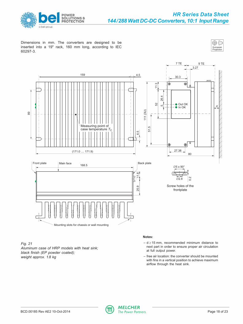
Notes:
– d ≥ 15 mm, recommended minimum distance tonext part in order to ensure proper air circulationat full output power.
– free air location: the converter should be mountedwith fins in a vertical position to achieve maximumairflow through the heat sink.
Fig. 21Aluminum case of HRP models with heat sink;black finish (EP powder coated);weight approx. 1.8 kg
EuropeanProjection
Dimensions in mm. The converters are designed to beinserted into a 19" rack, 160 mm long, according to IEC60297-3.
159 4.5
89
11
1 (
3U
)
168.5
d
80
6.5 5
1.5
3.27
7 TE 9 TE
25
.91
1.8
Front plate Main face Back plate
(171.0 .... 171.9)
JM093
Mounting slots for chassis or wall mounting
Screw holes of the
frontplate
∅5 x 90°
∅2.8 0.2
27.38
Out OKIn OK
26
.4
11
.3
552
30.3
Measuring point ofcase temperature TC
BCD.00185 Rev AE2 10-Oct-2014 Page 19 of 23MELCHERThe Power Partners.
HR Series Data Sheet144/288 Watt DC-DC Converters, 10:1 Input Range
6.5
11
.21
3
14
0
17.3 133.4 ±0.230
168
5 47.2
38.5
12
76
.5
11.8
11027
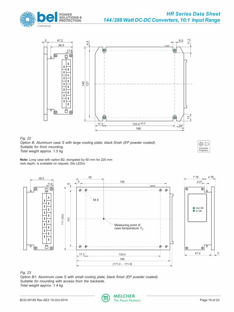
Fig. 22Option B: Aluminum case S with large cooling plate; black finish (EP powder coated).Suitable for front mounting.Total weight approx. 1.5 kg
Note: Long case with option B2, elongated by 60 mm for 220 mmrack depth, is available on request. (No LEDs)
EuropeanProjection
Fig. 23Option B1: Aluminum case S with small cooling plate; black finish (EP powder coated).Suitable for mounting with access from the backside.Total weight approx. 1.4 kg.
11
1 (
3U
)
17.3 133.4
168
10
1
547.2
1585
M 4
5
Measuring point ofcase temperature TC
50
(171.0 ... 171.9)
3.27
7 TE 4 TE
JM094
38.5
11.8
Out OK
In OK

BCD.00185 Rev AE2 10-Oct-2014 Page 20 of 23MELCHERThe Power Partners.
HR Series Data Sheet144/288 Watt DC-DC Converters, 10:1 Input Range
Fig. 24View of module's male connectors
Safety and Installation Instructions
Connector Pin AllocationThe connector pin allocation table defines the electricalpotentials and the physical pin positions on the H15connector. The protective earth is connected by a leading pin(no. 24), ensuring that it makes contact with the femaleconnector first.
Installation InstructionsThe converters are components, intended exclusively forinclusion within other equipment by an industrial assemblyoperation or by professional installers. Installation muststrictly follow the national safety regulations in compliancewith the enclosure, mounting, creepage, clearance, casualty,markings, and segregation requirements of the end-useapplication.
Connection to the system shall be made via the femaleconnector H15; see Accessories. Other installation methodsmay not meet the safety requirements.
S10002b
32 28 24 20 16 12 8 4
30 26 22 18 14 10 6
Fixtures for retention clips
Table 10: Pin allocation
Pin no. Name Function
4 Vo1+ Pos. output 1
6 Vo2+ Pos. output 2
8 Vo1– Neg. output 1
10 Vo2– Neg. output 2
12 S1+ Pos. sense line
14 S1– Neg. sense line
16 R Output voltage adjust
18 2 T Current share
20 D Out OK
22 1 PE Protection earth
24 PUL Programmable undervoltage lockout
26 + 28 Vi+ Pos. input
30 + 32 Vi– Neg. input
1 Leading pin (pre-connecting)2 Not connected for HRL models
Pin no. 22 ( ) is connected with the case. For safety reasonsit is essential to connect this pin reliably to protective earth.
Notes:– The PUL function (pin 24) must be programmed to enable the
outputs. PUL should be connected to Vi– (pins 30 + 32) by aresistor to adjust the start-up voltage; see table 3. Otherwise,the input current may become too high at low input voltage.
– Do not open the converter0, or warranty will be invalidated.
– If the second output of double-output models is not used,connect it parallel with the main output.
Make sure that there is sufficient airflow available forconvection cooling and verifiy it by measuring the casetemperature TC, when the converter is installed and operatedin the end-use application; see Thermal Considerations.
Ensure that a converter failure (e.g. an internal short-circuit)does not result in a hazardous condition.
Standards and ApprovalsThe converters are safety-approved to UL/CSA 60950-1 2nd
Ed. and IEC/EN 60950-1 2 nd Ed.
The converters correspond to Class I equipment (with caseconnected to ground). They have been evaluated for:
• Building-in
• Basic insulation between input and case based on 250 VA.Double or reinforced insulation between input and outputs
• Functional insulation between outputs
• Overvoltage category II
• Pollution degree 2 environment
• Max. altitude: 2000 m
• The converters fulfill the requirements of a fire enclosure.
The output voltage is considered as SELV, except HR/HRP2880 with both outputs in series connection.
The converters are subject to manufacturing surveillancein accordance with the above mentioned standards and ISO9001:2008. CB-scheme is available on request.
Cleaning LiquidsIn order to avoid possible damage, any penetration ofcleaning fluids has to be prevented, since the power suppliesare not hermetically sealed.
Protection DegreeThe protection degree is IP 40, provided that the femaleconnector is fitted to the converter.
Railway Application and Fire ProtectionThe converters have been designed by observing the railwaystandards EN 50155, EN 50121-3-2, and EN 50121-4. Allboards are coated with a protective lacquer.
The converters comply with NF-F16 (I2/F1). They also complywith EN 45545-1, EN 45545-2 (2013), if installed in a technicalcompartment or cabinet.

BCD.00185 Rev AE2 10-Oct-2014 Page 21 of 23MELCHERThe Power Partners.
HR Series Data Sheet144/288 Watt DC-DC Converters, 10:1 Input Range
Isolation and Protective EarthThe electric strength test is performed in the factory as routinetest according to EN 50116 and IEC/EN 60950 and should notbe repeated in the field. Power-One will not honor anywarranty claims resulting from electric strength field tests.The resistance case to the earth pin (<0.1 Ω) is tested as well.
Table 11: Isolation
Characteristic Input to case Output(s) to Output 1 to Unitand output(s) case output 2
Electric Factory test >1 s 2.8 1 1.4 0.3 kVDCstrength AC test voltage equivalent 2.0 1.0 0.21 kVACtest to factory test
Insulation resistance at 500 VDC >300 >300 >100 2 MΩ
Creepage distances ≥ 3.5 3 ≥ 2.5 -- mm
1 According to EN 50116 and IEC/EN 60950, subassemblies connecting input to output are pre-tested with 5.6 kVDC or 4 kVAC.2 Tested at 150 VDC3 Input to outputs: 6.4 mm
Description of Options
B, B1 Cooling PlatesWhere a cooling surface is available, we recommend the useof a cooling plate instead of the standard heat sink. Themounting system should ensure that the maximum casetemperature TC max is not exceeded. The cooling capacity iscalculated by (η see Model Selection):
(100% – η)PLoss = –––––––––– • Vo • Ioη
For the dimensions of the cooling plates; see MechanicalData.

BCD.00185 Rev AE2 10-Oct-2014 Page 22 of 23MELCHERThe Power Partners.
HR Series Data Sheet144/288 Watt DC-DC Converters, 10:1 Input Range
AccessoriesA variety of electrical and mechanical accessories areavailable including:
– Front panels for 19" DIN-rack: Schroff or Intermas, 12or 16TE /3U; see fig. 25.
– Mating H15 connectors with screw, solder, faston, orpress-fit terminals.
– Coding clips for connector coding HZZ00202
– Pair of connector retention clips HZZ01209-G
– Connector retention brackets HZZ01216-G (CRB-HKMS)
– Cable hood for H15 connectors:- HZZ00141-G, screw version- HZZ00142-G, use with retention brackets HZZ01218-G- HZZ00143-G, metallic version providing fire protection
– Cage clamp adapter HZZ00144-G; see fig. 28.
– DIN-rail mounting assembly HZZ0615-G (DMB-K/S)
– Wall-mounting plate K02 (HZZ01213-G) for models withoption B1
– Additional external input and output filters
– Different battery sensors S-KSMH... for using theconverter as a battery charger. Different cellcharacteristics can be selected; see fig. 32, table 12, andBattery Charging/Temperature Sensors.
For additional accessory product information, see theaccessory data sheets listed with each product series orindividual model at our web site:
www.belpowersolutions.com/power
Fig. 26Connector retention brackets HZZ01216-G (CRB-HKMS)
20 to 30 Ncm
Fig. 27Connector retention clips to fasten the H15 connector tothe rear plate; see fig. 24. HZZ01209-G consists of 2 clips.
Fig. 28Cage clamp adapter HZZ00144-G
Fig. 25Different front panels
BCD.00185 Rev AE2 10-Oct-2014 Page 23 of 23MELCHERThe Power Partners.
HR Series Data Sheet144/288 Watt DC-DC Converters, 10:1 Input Range
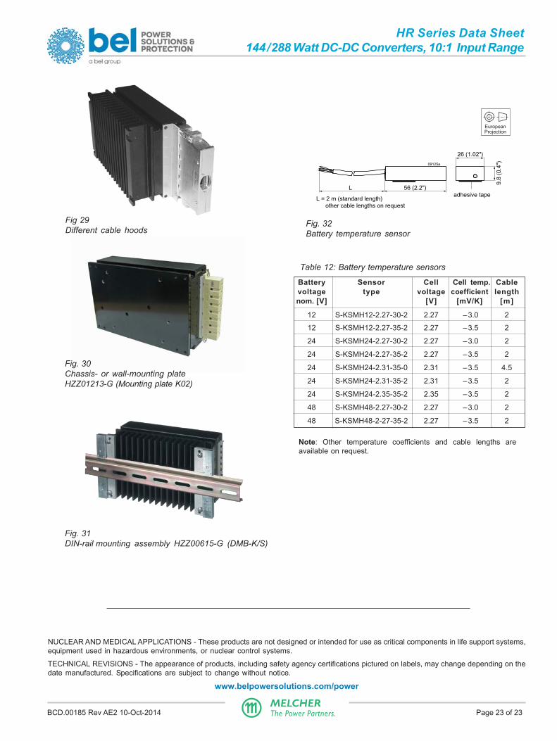
Fig. 30Chassis- or wall-mounting plateHZZ01213-G (Mounting plate K02)
56 (2.2")L
L = 2 m (standard length) other cable lengths on request
adhesive tape
26 (1.02")
9.8
(0.4
")09125a
Fig. 31DIN-rail mounting assembly HZZ00615-G (DMB-K/S)
Fig 29Different cable hoods
EuropeanProjection
Table 12: Battery temperature sensors
Battery Sensor Cell Cell temp. Cablevoltage type voltage coefficient lengthnom. [V] [V] [mV/K] [m]
12 S-KSMH12-2.27-30-2 2.27 –3.0 2
12 S-KSMH12-2.27-35-2 2.27 –3.5 2
24 S-KSMH24-2.27-30-2 2.27 –3.0 2
24 S-KSMH24-2.27-35-2 2.27 –3.5 2
24 S-KSMH24-2.31-35-0 2.31 –3.5 4.5
24 S-KSMH24-2.31-35-2 2.31 –3.5 2
24 S-KSMH24-2.35-35-2 2.35 –3.5 2
48 S-KSMH48-2.27-30-2 2.27 –3.0 2
48 S-KSMH48-2-27-35-2 2.27 –3.5 2
Fig. 32Battery temperature sensor
Note: Other temperature coefficients and cable lengths areavailable on request.
NUCLEAR AND MEDICAL APPLICATIONS - These products are not designed or intended for use as critical components in life support systems,equipment used in hazardous environments, or nuclear control systems.
TECHNICAL REVISIONS - The appearance of products, including safety agency certifications pictured on labels, may change depending on thedate manufactured. Specifications are subject to change without notice.
www.belpowersolutions.com/power