HQ Studio Frame for HQ18 Avanté - vw-handiquilter.storage ... · HQ Studio Frame for HQ18 Avanté...
24
HQ Studio Frame Assembly 1 Visit http://www.TheQuiltersAcademy.com FRONT BACK Handi Quilter, Inc. 445 N 700 W North Salt Lake, Utah 84054 © Handi Quilter 2011 Updated 08/09/11 Designed by a Quilter, for Quilters. ® HQ Studio Frame for HQ 18 Avanté Assembly Instructions Table of Contents Parts List page 2 Hardware List page 3 HQ Studio Frame Box Contents page 4 Step 1- Frame Side Assembly page 5 Step 2- Table Assembly page 6 Step 3- Middle Leg Assembly page 7 Step 4- End Leg Assembly page 8 Step 5- Precision-Glide Track Assembly page 11 Step 6- Ratchet Stop Assembly page 14 Step 7- Pole Bracket Assembly page 16 Step 8- Pole Coupler Assembly page 17 Step 9- Pole End Assembly (including Ratchet Wheel, Hand Wheel) page 18 Step 10- Pole to Frame Assembly page 21 Step 11- Rubber End Cap Assembly page 21 Step 12- Hook and Loop Strips Attachment page 22 Step 13- Bungee Clamp Assembly page 22 Step 14- Hook and Loop Strips on Poles Assembly page 23 Step 15- Attach Leaders page 23 Step 16- Adjusting HQ Studio Frame Height page 24 What’s Included Your HQ Studio Frame should have been delivered in four separate boxes. Upon opening, please check immediately to see if you have received the items listed in the Parts and Hardware lists found on pages 2, 3 and 4. In addition, the following items will be found in: Box 1. HQ Studio Frame Assembly Instructions Manual Box 4. (3) Leaders (3) Hook and loop strips to attach leaders to poles If you find you are missing any items, please contact Handi Quilter immediately at 1-877-697-8458 or 1-801-292-7988 or by emailing [email protected].
Transcript of HQ Studio Frame for HQ18 Avanté - vw-handiquilter.storage ... · HQ Studio Frame for HQ18 Avanté...

HQ Studio Frame Assembly 1Visit http://www.TheQuiltersAcademy.com
FRONTBACK
Handi Quilter, Inc.445 N 700 WNorth Salt Lake, Utah 84054
© Handi Quilter 2011
Updated 08/09/11
Designed by a Quilter, for Quilters.®
HQ Studio Frame for HQ18 AvantéAssembly InstructionsTable of Contents
FIG. 3-1
FIG. 4-1
MAIN PAGEFIG. 11-1FIG, 12-1FIG. 13-1
Parts List page 2Hardware List page 3HQ Studio Frame Box Contents page 4Step 1- Frame Side Assembly page 5Step 2- Table Assembly page 6Step 3- Middle Leg Assembly page 7Step 4- End Leg Assembly page 8Step 5- Precision-Glide Track Assembly page 11Step 6- Ratchet Stop Assembly page 14Step 7- Pole Bracket Assembly page 16Step 8- Pole Coupler Assembly page 17Step 9- Pole End Assembly (including Ratchet Wheel, Hand Wheel) page 18Step 10- Pole to Frame Assembly page 21Step 11- Rubber End Cap Assembly page 21Step 12- Hook and Loop Strips Attachment page 22Step 13- Bungee Clamp Assembly page 22Step 14- Hook and Loop Strips on Poles Assembly page 23Step 15- Attach Leaders page 23Step 16- Adjusting HQ Studio Frame Height page 24
What’s IncludedYour HQ Studio Frame should have been delivered in four separate boxes. Upon opening, please check immediately to see if you have received the items listed in the Parts and Hardware lists found on pages 2, 3 and 4. In addition, the following items will be found in:
Box 1. HQ Studio Frame Assembly Instructions ManualBox 4. (3) Leaders (3) Hook and loop strips to attach leaders to poles If you find you are missing any items, please contact Handi Quilter immediately at 1-877-697-8458 or 1-801-292-7988 or by emailing [email protected].

2 HQ Studio Frame Assembly Visit http://www.HandiQuilter.com
Fig. 6-1FIG. 6-2
TRACK SUPPORT
12FT BLACK PLASTIC TRACK
COUPLER
HQ Studio Frame Parts List
QF09318-512LEFT FRAME SIDE, BACK
QF09318-511
LEFT SIDE FRAME, FRONT
QF09318-412
RIGHT FRAME SIDE, BACK
QF09318-411RIGHT SIDE FRAME, FRONT
QF09318-700
POLE ASSYPOLE ASSY
QF09318-730QF09318-740
POLE ASSY
QF09318-512LEFT FRAME SIDE, BACK
QF09318-511
LEFT SIDE FRAME, FRONT
QF09318-412
RIGHT FRAME SIDE, BACK
QF09318-411RIGHT SIDE FRAME, FRONT
QF09318-700
POLE ASSYPOLE ASSY
QF09318-730QF09318-740
POLE ASSY
Table Splice Brace (4)
Box 3
Fig. 5-5Bottom minus screws
TABLE SECTION
RIGHT POLE BRACKET
MIDDLE LEG STAND
QF09318-500END LEG STAND, LEFT QF09318-400
END LEG STAND, RIGHT
BATTING BAR BRACKETQF09318-510
QF09318-410BATTING BAR BRACKET
QF09318-05TABLE SPLICE BRACE COUPLER
QF09318-01
Right Frame
Side Front (1)Box 3
Right Frame
Side Back (1)Box 3
Left Frame Side Front (1)
Box 3
Left Frame Side Back (1)
Box 3
Table Section (3)
2 in Box 1 and 1 in Box 4
Right Side Leg (1)Box 3
Frame Side Coupler (2)
Box 3
Fig. 5-5Bottom minus screws
Left Side Leg (1)Box 3
Fig. 6-1FIG. 6-2
TRACK SUPPORT
12FT BLACK PLASTIC TRACK
COUPLER
Track Support Section (6)
With table section: Four in Box 1 and two in Box 4
12ft Plastic Track (4) (Black)
Box 3
TABLE SECTION
RIGHT POLE BRACKET
MIDDLE LEG STAND
QF09318-500END LEG STAND, LEFT QF09318-400
END LEG STAND, RIGHT
BATTING BAR BRACKETQF09318-510
QF09318-410BATTING BAR BRACKET
QF09318-05TABLE SPLICE BRACE COUPLER
QF09318-01
Track SupportCoupler (4)
Box 3
Bungee Clamp (4)Box 3
Hook and Loop Strip (2)
4’ Pole Section
Ten in Box 2 and five in Box 4
(Note: 10’ frame has ten 4’ poles
in Box 2 and five 2’ in Box 4)
Fig. 9-1Fig. 9-2
Fig. 8-1
Fig. 9-4
Fig. 9-3
Fig. 6-1FIG. 6-2
TRACK SUPPORT
12FT BLACK PLASTIC TRACK
COUPLER
Fig. 9-1Fig. 9-2
Fig. 8-1
Fig. 9-4
Fig. 9-3
2’ Coupler (10)Box 2
TABLE SECTION
RIGHT POLE BRACKET
MIDDLE LEG STAND
QF09318-500END LEG STAND, LEFTQF09318-400
END LEG STAND, RIGHT
BATTING BAR BRACKETQF09318-510
QF09318-410BATTING BAR BRACKET
QF09318-05TABLE SPLICE BRACECOUPLER
QF09318-01
Middle Leg (2)Box 3
Plugged-Hole Pole Bracket (1)
Box 1
Open-Hole Pole Bracket (1)
Box 1

HQ Studio Frame Assembly 3Visit http://www.TheQuiltersAcademy.com
HQ Studio Frame Hardware List
M8 x 25mm Socket Button
Head Cap Screw (SBHCS)
(4)
M8 Lock Nut(4)
M8 Flat Washer(4)
17/13/16mmWrench
(1)
5mm Allen Wrench
(1)
Short Bolt Ratchet Wheel Assembly
(2)Long Bolt Ratchet Wheel Assembly
(1)
Leveling Foot(8)
Rubber End Cap(10)
4mm Allen Wrench
(1)
M8 x 16mm Socket Button Head Cap Screw (SBHCS)
(64 total)
M5 x 8mm Socket Button
Head Cap Screw (SBHCS)(24 total)
M6 x 12mm Connector Screw
(12 total)(8 in Box 1)(4 in Box 3)
Hand Wheel Assembly
(1)
HAND WHEEL ASSY
QF09318-720SHORT BOLT RATCHET WHEEL
QF09318-730 QF09318-730LONG BOLT RATCHET WHEEL
HAND WHEEL ASSY
QF09318-720SHORT BOLT RATCHET WHEEL
QF09318-730 QF09318-730LONG BOLT RATCHET WHEEL
HAND WHEEL ASSY
QF09318-720SHORT BOLT RATCHET WHEEL
QF09318-730 QF09318-730LONG BOLT RATCHET WHEEL
M6 x 45mmConnector
Screw(3)
Ratchet Stop(3)
Ratchet-StopBushing
(3)
Pole End Assembly
(7)
HAND WHEEL ASSY
QF09318-720SHORT BOLT RATCHET WHEEL
QF09318-730 QF09318-730LONG BOLT RATCHET WHEEL
HAND WHEEL ASSY
QF09318-720SHORT BOLT RATCHET WHEEL
QF09318-730 QF09318-730LONG BOLT RATCHET WHEEL
HAND WHEEL ASSY
QF09318-720SHORT BOLT RATCHET WHEEL
QF09318-730 QF09318-730LONG BOLT RATCHET WHEEL
3mm Allen Wrench
(1)
These parts found in Box #3
QF09318-103BUNGEE HOLDER
BUNGEE HOLDER COVER
QF09318-104
BUNGEE HOLDER SPACER
QF09318-103
RATCHET STOP
QF09318-203
RATCHET STOP HOLDER
QF09318-205
RATCHET STOP BUSHING
QF09318-201
CONNECTOR BOLT
QF09318-204QF09318-202
RATCHET STOP MOUNTRAIL BEARING SNAP
QF09318-105RAIL BEARING SNAP COVER
QF09318-106
Fig. 10-2
QF09318-105
QF09318-703OUTSIDE POLE END V-GROOVE BEARING
QF09318-705QF09318-713
HAND WHEEL COLLARQF09318-714
STEEL SNAPPING BUTTON/LOCKING CLIPLEVELING FOOT
QF09318-103BUNGEE HOLDER BUNGEE HOLDER COVER
QF09318-104
BUNGEE HOLDER SPACER
QF09318-103
RATCHET STOP
QF09318-203
RATCHET STOP HOLDER
QF09318-205
RATCHET STOP BUSHING
QF09318-201
CONNECTOR BOLT
QF09318-204QF09318-202
RATCHET STOP MOUNTRAIL BEARING SNAP
QF09318-105RAIL BEARING SNAP COVER
QF09318-106
Fig. 10-2
QF09318-105
QF09318-703OUTSIDE POLE END V-GROOVE BEARING
QF09318-705QF09318-713
HAND WHEEL COLLARQF09318-714
STEEL SNAPPING BUTTON/LOCKING CLIPLEVELING FOOT
Ratchet-StopMount
(3)
QF09318-103BUNGEE HOLDER BUNGEE HOLDER COVER
QF09318-104
BUNGEE HOLDER SPACER
QF09318-103
RATCHET STOP
QF09318-203
RATCHET STOP HOLDER
QF09318-205
RATCHET STOP BUSHING
QF09318-201
CONNECTOR BOLT
QF09318-204QF09318-202
RATCHET STOP MOUNTRAIL BEARING SNAP
QF09318-105RAIL BEARING SNAP COVER
QF09318-106
Fig. 10-2
QF09318-105
QF09318-703OUTSIDE POLE END V-GROOVE BEARING
QF09318-705QF09318-713
HAND WHEEL COLLARQF09318-714
STEEL SNAPPING BUTTON/LOCKING CLIPLEVELING FOOT
Ratchet-StopHolder
(3)
Hand Wheel Insert (1)May be preassembled
with Hand Wheel.
QF09318-103BUNGEE HOLDER BUNGEE HOLDER COVER
QF09318-104
BUNGEE HOLDER SPACER
QF09318-103
RATCHET STOP
QF09318-203
RATCHET STOP HOLDER
QF09318-205
RATCHET STOP BUSHING
QF09318-201
CONNECTOR BOLT
QF09318-204QF09318-202
RATCHET STOP MOUNTRAIL BEARING SNAP
QF09318-105RAIL BEARING SNAP COVER
QF09318-106
Fig. 10-2
QF09318-105
QF09318-703OUTSIDE POLE END V-GROOVE BEARING
QF09318-705QF09318-713
HAND WHEEL COLLARQF09318-714
STEEL SNAPPING BUTTON/LOCKING CLIPLEVELING FOOT
Fig. 9-1
Fig. 9-2
Fig. 8-1
Fig. 9-4
Fig. 9-3

4 HQ Studio Frame Assembly Visit http://www.HandiQuilter.com
BoxNo. Parts
1 Two 4-foot table sections with track supports (4) , M6 X 12mm Connector screw (8) and left and right pole brackets
2 10 poles, 10 couplers
3 All other parts (including plastic tracks)
4 One 4-foot table section w/track supports (2), M6 X 12mm Connector screw (4), five 4-foot poles
BoxNo. Parts
4 One 2-foot table section with track supports (2), M6 X 12mm Connector screw (4), five 2-foot poles
12' frame
10' frame (Boxes 1, 2 & 3 same as 12-foot)
HQ Studio Frame Box Contents

HQ Studio Frame Assembly 5Visit http://www.TheQuiltersAcademy.com
Step 1: Frame Side Assembly
Parts needed1-Right Side Leg1-Left Side Leg1-Right Frame Side Front1-Left Frame Side Front1-Right Frame Side Back1-Left Frame Side Back4-Leveling Feet16-M8 x 16mm SBHCS
Tools Required5mm Allen Wrench (Provided)
1-1: Screw two (2) leveling feet about half way into the bottom of the left side leg, as shown in Fig. 1-1.
1-2: Attach the left frame side back onto the side leg using two M8 x 16mm SBHCS into the back of the back leg. Next install two more M8 x 16mm SBHCS into the side of the back leg. Finger-tighten the screws only for now. You will tighten the screws with an Allen wrench later in Step 4.8.
1-3: Attach the left frame side front onto the side leg using two M8 x 16mm SBHCS into the front of the front leg. Next install two more M8 x
Note: Make sure both height- adjustable legs are at their shortest setting before proceeding.
Remember that the batting bar bracket needs to be on the outside of the leg. (Fig. 1-1)
16mm SBHCS into the side of the front leg. Finger-tighten the screws only for now. You will tighten the screws with an Allen wrench later in Step 4.8.
1-4: Using remaining parts, repeat Steps 1-1 through 1-3 to complete the right side leg.
Step 1Frame Side Assembly
Note: Assembly is easiest if all connections are finger-tightened first as instructed, while assembling the frame. Tighten with the wrench when instructed.
Why is this important? If you tighten as you go, you may have trouble getting all the parts to align properly.
Fig. 10-1
Fig. 9-6
Fig. 2-1
Fig. 1-1Fig. 1-1
Left Side Leg
Left Frame Side Front
Back Leg Front Leg
Batting Bar Bracket
Left Frame Side Back
QF09318-103BUNGEE HOLDER
BUNGEE HOLDER COVER
QF09318-104
BUNGEE HOLDER SPACER
QF09318-103
RATCHET STOP
QF09318-203
RATCHET STOP HOLDER
QF09318-205
RATCHET STOP BUSHING
QF09318-201
CONNECTOR BOLT
QF09318-204QF09318-202
RATCHET STOP MOUNTRAIL BEARING SNAP
QF09318-105RAIL BEARING SNAP COVER
QF09318-106
Fig. 10-2
QF09318-105
QF09318-703OUTSIDE POLE END V-GROOVE BEARING
QF09318-705QF09318-713
HAND WHEEL COLLARQF09318-714
STEEL SNAPPING BUTTON/LOCKING CLIPLEVELING FOOT
M8 X 16 SBHCS X 4
M8 X 16 SBHCS X 4
Leveling Feet

6 HQ Studio Frame Assembly Visit http://www.HandiQuilter.com
Fig. 10-1
Fig. 9-6
Fig. 2-1
Fig. 1-1
Fig. 2-1
Step 2: Table Assembly
Parts needed3- Table Sections 12’: Three 4’ sections 10’: Two 4’ sections One 2’ section4- Table Splice Brace24- M8 x 16mm SBHCS
Tools Required5mm Allen Wrench (Provided)
2-1: Prepare the three table sections by removing the two track supports screws from each track support. Set the track supports aside. These will be reinstalled in Step 5 see Fig. 5-5.These were assembled on the table temporaily to protect them during shipping.
2-2: 12 foot: Start with Two 4-foot table sections upside-down on the floor end to end. 10 foot: start with one 2-foot and one 4-foot table sections upside-down on the floor end to end (as shown in Fig. 2-1). Join the sections together by placing a table splice brace onto the sections, lining up the holes in the brace with those in the sections. Make sure the flange portion of the brace is on top (as shown).
2-3: Place four (4) M8 x 16mm SBHCS through the side of each table splice brace and finger-tighten them into the table sections.
2-4: Finger-tighten two (2) SBHCS through the top of each table splice brace (as shown). (Fig. 2-1)
2-5: Repeat Steps 2-1 through 2-3 to add remaining 4-foot section. On the 10’ frame the 2’ section goes in the center.
Step 2 Table Assembly
NOTE: For this step, a carpeted surface is recommended for the protection of your floor and frame.
If you are working on a hard surface (such as tile, hardwoods or concrete), cover the surface with a blanket or rug.
NOTE: Remember to finger- tighten all screws first. Once all are in place, then tighten using the 5mm Allen wrench (provided) as instructed.
Note: Skip Steps 2 and 3 if you are only setting the frame up at four feet (4’). The 12’ frame uses a 4’ center/middle table section. The 10’ frame uses a 2’ center/middle table section.
Table Splice Brace
2-6: Pull the two table sections as close together as possible to remove gap. (This will facilitate assembly of the middle legs in Step 3.)
2-7 : Using the 5mm Allen wrench, tighten the four side screws on each table splice brace, until the brace touches the side of the table frames, and then loosen the screws ½ turn.
2-8: Tighten fully the two (2) top screws on each table splice brace, using the 5mm Allen wrench. Now fully tighten the 4 screws on the side of each table splice brace. All 24 screws should now be tightened.
M8 x 16mm SBHCS
M8 x 16mm SBHCS
Fig. 10-1
Fig. 9-6
Fig. 2-1
Fig. 1-1

HQ Studio Frame Assembly 7Visit http://www.TheQuiltersAcademy.com
Step 3: Middle Leg Assembly
Parts needed1- Table Assembly2- Middle Legs4- Leveling Feet8- M8 x 16mm SBHCS
Tools Required5mm Allen Wrench (Provided)
3-1: Install two (2) leveling feet about half way into one middle leg.
3-2: Place the middle leg assembly over two joined table sections. Attach the middle leg assembly using four (4) M8 x 16mm SBHCS.
3-3: While pushing down on the leg, fully tighten the four (4) screws.
Step 3Middle Leg Assembly
Note: If instructions were carefully followed in Section 2, there should be minimal gap between the table sections where the sections meet. The middle leg/legs should slide over the two table section end tubes easily. Check to ensure that all table splice brace screws are tightened before tightening the four middle leg screws.
3-4: Repeat Steps 3-1 through 3-3 to attach remaining middle leg. Be sure middle leg assemblies are set at the lowest settings and that the height adjustment levers are facing in the same direction, towards the back of the table as shown in Fig. 3-1.
Table Assembly
Middle Leg
Height Adjustment Lever
Front
FIG. 3-1
FIG. 4-1
Back
Fig. 3-1
Note: The direction the height adjustment levers face determine the back of the frame in this step.

8 HQ Studio Frame Assembly Visit http://www.HandiQuilter.com
Left Leg Assembly
Height Adjustable Lever
Table Assembly
FIG. 3-1
FIG. 4-1Fig. 4-1
Step 4End Leg Assembly
Note: Finger-tighten screws only until all screws are in place, they will be tightened after the table is up- righted once again. See Step 4-8.
Step 4: End Leg Assembly
Parts needed1- Table Assembly1- Right Leg Assembly1- Left Leg Assembly2 - Frame Side Coupler16- M8 x 16mm SBHCS
Tools Required5mm Allen Wrench (Provided)Spirit Level (Not Provided) 4-1: In preparation for attaching the left and right leg assemblies to the frame, turn the frame on its side so the height adjustable levers are towards the ground, as shown in Fig. 4-1.
4-2: Slide the left leg assembly under the table assembly.
Right Leg Assembly

HQ Studio Frame Assembly 9Visit http://www.TheQuiltersAcademy.com
Step 4: End Leg Assembly (continued)
4-3: Starting at the top left corner, screw two (2) M8 X 16mm SBHCS down through the top corner Left Frame Side Front piece into the table frame Fig. 4-2, finger-tighten only.(Fully tighten in Step 4-8)
4-4: Align the Frame Side Coupler to the holes in the Left Frame Side Front and the Left Frame Side Back and screw four (4) screws thru the Coupler, the Frame Side and into the Table Section Fig. 4-2.
4-5: Repeat Steps 4-2 through 4-4 for the Right Leg Assembly.
4-6: With the help of a second person, rotate the frame so it is standing in the upright position.
4-7: Attach two (2) M8 x 16mm SBHCS each through the back side of the left and right leg assemblies, and finger-tighten only.
Step 4End Leg Assembly (continued)
Note: Make sure all height-adjustable legs are at their shortest setting before proceeding with Step 4-6.
Fig. 4-2
Use M8 x 16mm SBHCS here and
in all shown holes
Top Left Corner

10 HQ Studio Frame Assembly Visit http://www.HandiQuilter.com
4-8: Next, ensure that the table assembly is down on top of the left and right leg assemblies, at all four corners, by applying the appropriate pressure or support, (there should be little to no gap between the bottom of the table assembly and the top of each leg) see Fig. 4-3. Now using the 5mm Allen Wrench, tighten the 4 screws at each corner to the table assembly (8 screws per end). Also tighten the 4 screws at each frame side to each leg at this time (8 more screws per end). If necessary have a second person help check and hold this while tightening the screws.
4-9: At this point, all screws should be tightened on the table. Double-check all M8X 16mm screws to make sure they are tightened, using the 5mm Allen tool.
4-10: Using a spirit level, check andadjust the frame top to be level in theplace where it will be used, both frontto back and side to side, by adjustingthe leveling feet. Double-check that the table-top frame to ensure that it isflat at each table splice brace and notsagging or high at the joints (Fig. 4-4).If no spirit level is available, check thetable with the machine on the carriageand the Precision-Glide tracks afterthey are installed in Step 5 and adjustappropriately. When the table is level,the machine should stay where youput it and not roll forward, back or sideto side.
QF09318Fig. 5-5
Fig. 4-4
Step 4End Leg Assembly (continued)
Little to no gap here on all four corners
Fig. 4-3

HQ Studio Frame Assembly 11Visit http://www.TheQuiltersAcademy.com
Step 5 Precision-Glide Track Assembly
end of each section to serve as a stop screw (Fig. 5-1, Fig. 5-2). Fully tighten screw. This will help align the coupler properly into the two track support sections when joined.
5-4: Insert a coupler into one prepared end of one track support section up to the stop screw. Thread an M5 X 8 mm SBHCS into the first hole and lightly tighten as shown in Fig. 5-2. Insert the other end of the coupler into second prepared track support section. Hold the two adjoining track support sections tightly together and thread an M5 X 8mm SBHCS into the first hole of the second track support and lightly tighten (shown in Fig. 5-2). You may need to gently rock the track support to seat the coupler. Finally, insert a second screw into the track supports, align and tighten.
5-5: Repeat steps 5-3 and 5-4 to join remaining track support section to center track support section to assembly one (1) track support. Once alignment is assured, tighten all screws firmly.
Note: The aluminum track support sections are cut from single sections of extruded aluminum and should align when placed end to end. However, if all directions in Step 5-4 are followed and track supports still do not align properly, try swapping track support sections, so that different ends are joining.
Step 5: Precision-Glide Track Assembly
Parts needed1- Table6- 4-foot Track Support4- Track Support Couplers24- M5 X 8mm SBHCS12- M6 x 12mm Connector Screw4- 12’ Plastic Tracks (Black)
Tools Required3mm Allen Wrench (Provided)4mm Allen Wrench (Provided)
5-1: Check inside the ends of the track supports for burrs or debris and remove all foreign matter from the inside.
5-2: Lay three track-support sections on the table upside down, with the wider lip of the sections facing toward the outside of the table (Fig. 5-1).
5-3: To prepare for joining one end and the center support sections together, screw one M5X 8mm SBHCS into the third hole from each splice
Fig. 5-1QF09318-02
Fig. 5-2QF09318-02
Fig. 5-3QF09318-02
Fig. 5-4QF09318-02
M5 x 8mm SBHCS
Track Support
Track Support shown upside down.
Second Hole
Place the track support upside down with the lip toward the outside of the table.
First Hole
Third Hole for stop screws
Fig. 5-1Fig. 5-1
QF09318-02
Fig. 5-2QF09318-02
Fig. 5-3QF09318-02
Fig. 5-4QF09318-02
Stop Screws M5 x 8mm SBHCS
Coupler Fig. 5-2
Center Section
End Section

12 HQ Studio Frame Assembly Visit http://www.HandiQuilter.com
QF09318Fig. 5-5
Fig. 5-5Bottom minus screws
5-6: Insert a plastic track completely into one side of the aluminum track supports. The plastic track should slide into the track support easily. If a plastic track binds slightly, try backing the track out a little, then try pushing it further. If the plastic binds badly, check the track supports for debris, burrs, misalignment or damage. (Fig. 5-3)In same manner, insert plastic track in otherside of the track support.
5-7: Repeat Steps 5-1 through 5-6 to make second track.
5-8: Attach Tracks. Secure one assembled track to the back of the quilting frame. Line up the track support by holding it tightly against the plastic tabletop as you secure it to the frame, using six (6) M6 x 12mm connector screws, as shown in Fig. 5-4. Do not tighten screws at
M6 x 12mm
Connector Bolt
NOTE: The extrusions have a wider shoulder on one edge of the track. This shoulder is to be placed toward the inside of the table over the edge of the black plastic tabletop. (Fig. 5.5)
Fig. 5-5
Wider shoulders to inside
Fig. 5-4
Track Support
M6 x 12mm Connector Bolt
Back of Table
Front of Table
NOTE: The track support surfaces must be perfectly aligned. Otherwise, the quilter will feel a bump and quilt stitches will be adversely affected.
Fig. 5-3Plastic Track
Track Support

HQ Studio Frame Assembly 13Visit http://www.TheQuiltersAcademy.com
this time. They need to be loose to accommodate adjustments in Step 5-9. In same manner, attach the remaining track support to the front of the frame using six (6) M6 x 12mm connector bolts.
5-9: Align Tracks. Place the carriageon the tracks at one end of the table.Roll back and forth along the lengthof the table, establishing the distancebetween the two tracks, taking careto check that the wheels are engagingthe track on both the front and theback of the carriage. Move both tracksin tandem to the back of table asfar as possible. (Slots in the tablesallow this movement.) Double-checkthat the back track is straight along theback edge of the table. Fully tightenthe screws in the BACK track only fornow.
5-10: Place the machine onto the carriage and again, roll it the entire length of the frame, working the tracks into the wheels as you go. Lightly tighten the front track support screws as you move down the table. Check the carriage to verify that it rolls smoothly and that both ends of the carriage are engaging the tracks. If you find a section of track where the carriage rocks back and forth when moved all the way forward or back, loosen the front track support screws, and adjust the front track until the carriage rolls smoothly and does not rock, then re-tighten the front track screws.
Step 5 Precision-Glide Track Assembly
5-11: Finally, fully tighten the front track to the table.

14 HQ Studio Frame Assembly Visit http://www.HandiQuilter.com
Fig. 6-1
Ratchet Stop Holder
Ratchet Stop Mount
Ratchet Stop Bushing
Ratchet Stop
M6 x 45mm Connector Screw
Step 6Ratchet Stop Assembly
6-2: Identify the open-hole pole bracket and the plugged-hole pole bracket. The plugged hole pole bracket can be used “as-is” on either the left or right side, depending on the decision made about which side the hand wheel will be on. Set the plugged hole pole bracket aside at this time.
The ratchet stops and ratchet-stop holder will be assembled into the open-hole pole bracket, but the orientation of the stops and holders will vary, depending upon whether the pole bracket is used on the right or the left side of the table. The instructions that follow assume that the open pole bracket (and hand wheel) will be used on the right side of the table.
6-3: Place one ratchet-stop holder between the two metal pieces at the back of the open-hole pole bracket, with the stop nub facing inside, as
Step 6: Ratchet Stop Assembly
Parts needed1- Open-hole Pole Bracket3- M6 x 45mm Connector Screw3- Ratchet-Stop3- Ratchet-Stop Bushing3- Ratchet-Stop Mount3- Ratchet-Stop Holder
Tools Required4mm Allen Wrench (Provided)
6-1: Decide whether you want the ratchets and hand wheel to be on the left or the right side of the frame. The following instructions show how to assemble the frame with the hand wheel on the right side of the frame, which is the most common setup. If you prefer the hand wheel to be on the left side of the frame, see “Left Side Option” on page 15.
Fig. 6-2Outside
Inside
Nub
Ratchet Stop
Ratchet Stop Holder
Pole Bearing
Loosen if necessary

HQ Studio Frame Assembly 15Visit http://www.TheQuiltersAcademy.com
shown in Fig. 6-1. If the ratchetstop holder will not fit, loosen thetwo pole-bearing screws nearestthe square hole. Slide in the ratchetstop holder and re-tighten when finished.
6-4: Following the parts order in the circled detail in Fig. 6.1, thread one M6 x 45mm connector screw through a ratchet stop, ratchet stop bushing, pole bracket (with ratchet stop holder inserted) and finally into the ratchet-stop mount. Pay close attention to the orientation of the ratchet stop. Tighten with the 4mm Allen tool until the rachet stop holder nub holds the rachet stop, see Fig 6-2 circle detail.
6-5: In same manner, attach the remaining ratchet stops and ratchet stop holders to the front of the pole bracket, paying attention to the orientation of the ratchet stops (Figs. 6-1 and 6-2) to create the right pole bracket.
Left Side OptionIf assembling with the hand wheel and ratchets on the left side, remember that the ratchet stops and the ratchet stop holder nubs go to the inside of the pole bracket when it is attached to the table. Keeping this in mind, follow Steps 6-2 through 6-5 to assemble the left pole bracket, reversing the direction of the ratchet stop, ratchet stop bushing, ratchet stop holder and ratchet-stop mount shown in Fig. 6-2.

16 HQ Studio Frame Assembly Visit http://www.HandiQuilter.com
7-2: Visually level the pole bracketassembly and fully tighten the twoscrews with 13/17 mm wrench &5mm Allen wrench provided.
7-3: Repeat Step 7-1 & Step 7-2 to attach the open-hole pole bracket w/ratchet stops assembly, making sure the ratchet stops are on the inside of the frame.
Step 7: Pole Bracket Assembly
Parts needed1- Table1- Open-hole Pole Bracket w/Ratchet Stops Assembly1- Plugged-hole Pole Bracket4- M8 x 25mm SBHCS4- M8 Flat Washer4- M8 Lock Nut
Tools Required13/17 mm Wrench (Provided)5mm Allen Wrench (Provided)
7-1: Slide the plugged-hole pole bracket down over the metal frame mount on the left frame side front. The pole bracket should straddle the frame mount. Attach the plugged-hole pole bracket to the frame using two (2) M8 x 25mm SBHCS. Thread the screws through the second hole from the bottom of the pole bracket from the outside to the inside of the frame. On the end of each screw, slide a flat washer followed by a lock nut, as shown in Fig. 7-1.
Fig. 7-1
Table Assembly
Left Pole BracketM8 Lock Nut
M8 x 25mm SBHCS
M8 Flat Washer
QF09318Fig. 5-5
QF09318Fig. 7-1
Step 7 Pole Bracket Assembly
QF09318Fig. 5-5
QF09318Fig. 7-1
Frame Mount
NOTE: If setting frame up with hand wheel on the left side of frame, reverse postition (switch sides) of pole brackets.
Use second set of holes up for pole
bracket

HQ Studio Frame Assembly 17Visit http://www.TheQuiltersAcademy.com
NOTE: Your frame comes with 15 pole sections, which enable you to create 5 completed pole assemblies (the 4-foot size uses five pole sections, 8-foot uses 10 pole sections and 5 couplers, and the 12-foot uses all 15 pole sections and all 10 couplers).
Step 8: Pole Coupler Assembly
Parts needed15 Pole sections10 Pole couplers
Note: Instructions below are for assembling 12’ pole assemblies using three 4-foot pole sections for each of five poles. See alternate instructions for different size frames below:
4-foot frame: Skip Step 8 and proceed to Step 9.8-foot frame: Use two 4-foot pole sections for each of five poles.10-foot frame: Use two 4-foot and one 2-foot pole section for each of five poles. Place the 2-foot pole section in the center of the final pole assembly.
8-1: Join two 4-foot pole sectionstogether by inserting a pole couplerinto the end of one pole section (as shown in Fig. 8-1), depressing the spring button as it slides in. Continue sliding until the spring button pops out of the hole in the pole section. Repeat to add second 4-foot pole section to the first.
8-2: In same manner, add final 4-foot pole section to section completed in Step 8-1 to complete one 12-foot pole assembly.
8-3: Using remaining couplers and pole sections, repeat steps 8-1 and 8-2 to complete four more 12-foot pole assemblies for a total of 5 pole assemblies.
Step 8 Pole Assembly
Fig. 9-1 Fig. 9-2
Fig. 8-1
Fig. 9-4
Fig. 9-3
Fig. 8-1
NOTE: If you are assembling a four foot (4’) frame, you may skip Step 8 and proceed to Step 9.
NOTE: 10- foot frame uses 10 four-foot poles and 5 two-foot poles. The two foot sections go in the center.
IMPORTANT: Be careful when assembling poles to not pinch your hands between pole parts while sliding them together.
Pole Coupler
Pole Section

18 HQ Studio Frame Assembly Visit http://www.HandiQuilter.com
Step 9: Pole End Assembly
Parts needed5- Pole Assemblies7- Pole Ends2- Short-Bolt Ratchet Wheel Assemblies1- Long-Bolt Ratchet Wheel Assembly1- Hand Wheel
Tools Required13/17 mm Wrench (Provided)
Pole End Assembly 9-1: Check one pole end to ensure that it matches Figs. 9-1 and 9-3.
9-2: Loosen the nut on the pole end until it nearly reaches the end of the bolt.
9-3: Holding onto the outside pole end, push the nut end of the bolt towards the opposite end of the assembly, until the inside pole end short bolt wedge slides out (Fig. 9-2). This makes the outside diameter of the pole end narrower and ready to be inserted into the end of the pole assembly.
9-4: Repeat Steps 9-1 through 9-3 to prepare the remaining 6 pole ends for insertion.
Step 9 Adding the Pole Ends
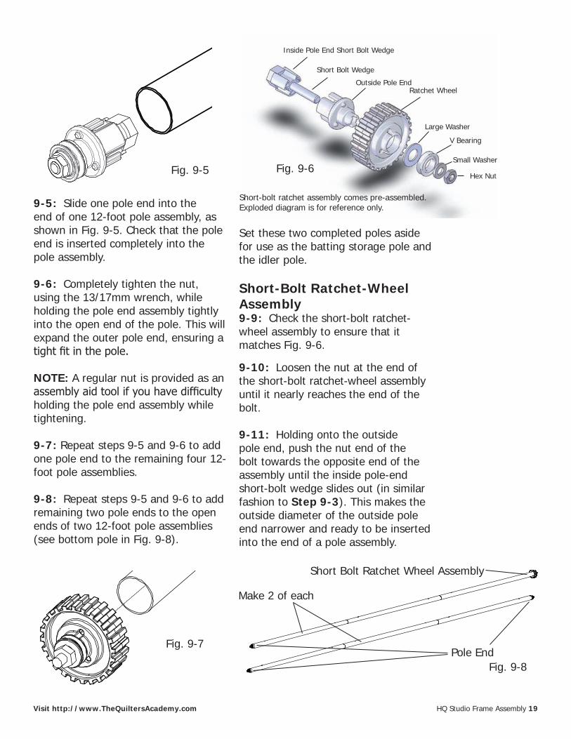
Inside Pole End Short Bolt Wedge
Outside Pole End
Large Washer
V Bearing
Small Washer
Lock Nut
Fig. 9-3
Pole End
Pole End assembly comes pre-assembled. Exploded diagram is for reference only.
Fig. 9-1 Fig. 9-2
Fig. 8-1
Fig. 9-4
Fig. 9-3
Pole End Fig. 9-1
Fig. 9-2
Loosen nut then push
Fig. 9-1 Fig. 9-2
Fig. 8-1
Fig. 9-4
Fig. 9-3
Wedge Slides Out
HQ Studio Frame Assembly 19Visit http://www.TheQuiltersAcademy.com
Fig. 9-7
9-5: Slide one pole end into the end of one 12-foot pole assembly, as shown in Fig. 9-5. Check that the pole end is inserted completely into the pole assembly.
9-6: Completely tighten the nut, using the 13/17mm wrench, while holding the pole end assembly tightly into the open end of the pole. This will expand the outer pole end, ensuring a tight fit in the pole.
NOTE: A regular nut is provided as an assembly aid tool if you have difficulty holding the pole end assembly while tightening.
9-7: Repeat steps 9-5 and 9-6 to add one pole end to the remaining four 12-foot pole assemblies.
9-8: Repeat steps 9-5 and 9-6 to add remaining two pole ends to the open ends of two 12-foot pole assemblies (see bottom pole in Fig. 9-8).
Set these two completed poles aside for use as the batting storage pole and the idler pole.
Short-Bolt Ratchet-Wheel Assembly9-9: Check the short-bolt ratchet-wheel assembly to ensure that it matches Fig. 9-6.
9-10: Loosen the nut at the end of the short-bolt ratchet-wheel assembly until it nearly reaches the end of the bolt.
9-11: Holding onto the outside pole end, push the nut end of the bolt towards the opposite end of the assembly until the inside pole-end short-bolt wedge slides out (in similar fashion to Step 9-3). This makes the outside diameter of the outside pole end narrower and ready to be inserted into the end of a pole assembly.
Fig. 9-5
Fig. 9-1 Fig. 9-2
Fig. 8-1
Fig. 9-4
Fig. 9-3
Fig. 9-1
Fig. 9-2
Fig. 8-1
Fig. 9-4
Fig. 9-3
Outside Pole End
Inside Pole End Short Bolt Wedge
Short Bolt Wedge
Ratchet Wheel
Large Washer
V Bearing
Small Washer
Hex NutFig. 9-6
Short-bolt ratchet assembly comes pre-assembled. Exploded diagram is for reference only.
Fig. 10-1
Fig. 9-6
Fig. 2-1
Fig. 1-1
Fig. 9-8
Make 2 of each
Short Bolt Ratchet Wheel Assembly
Pole End

20 HQ Studio Frame Assembly Visit http://www.HandiQuilter.com
Fig. 9-9
Long Bolt Ratchet Wheel and Hand Wheel Assembly
Ratchet Wheel
Hand Wheel
Small Washer
Lock NutLarge Washer
V Bearing
Outside Pole End
Inside Pole End Long Bolt Wedge
Fig. 9-10
Make one.
Long Bolt Ratchet Wheel and Hand Wheel
Pole End
Hand WheelInsert
Hand Wheel Assembly9-12: Check the long-bolt ratchet-wheel assembly to ensure that it matches Fig. 9-9.
9-13: Add the hand wheel assembly to the long-bolt ratchet-wheel assembly as shown in Fig. 9-9, aligning the three tabs on the hand-wheel insert with the three notches on the outside pole end. If the three tabs are not properly aligned, the hand wheel will spin freely, independent of the pole. The goal is to have the three tabs engaged, so turning the hand wheel will turn the pole.
9-14: Repeat step 9-11 to prepare the long-bolt ratchet wheel and hand wheel assembly for insertion.
Ratchet Wheel and Hand Wheel Insertion9-15: Insert one short-bolt ratchet wheel assembly into the open end of a pole assembly as shown in Fig. 9-7 on page 19. Check that the pole end is inserted completely into the pole assembly.
9-16: Completely tighten the nut, using the 13/17 mm wrench, while holding the short-bolt ratchet-wheel assembly tightly into the open end of
the pole. This will expand the outer pole end, ensuring a tight fit in the pole. Make sure the 3 tabs on the outside pole end, align with the 3 holes in the ratchet wheel, see Fig 9-9. This completes the backing pole.
9-17: Repeat steps 9-15 and 9-16 to complete the quilt-top pole. Set both poles aside.
9-18: In same manner, slide the long-bolt ratchet wheel and hand wheel assembly into the open end of the remaining pole assembly and while holding the complete assembly tightly into the open end of the pole tighten the nut, using the 13/17 mm wrench. Check to be sure the hand wheel engages the ratchet wheel assembly
Long bolt ratchet wheel comes pre-assembled. Exploded diagram is included for reference.
TabHole
and does not spin loosely and that the 3 tabs of the outside pole end align with the 3 holes in the ratchet wheel. This completes the take-up pole.

HQ Studio Frame Assembly 21Visit http://www.TheQuiltersAcademy.com
Step 10: Pole to Frame Assembly
Parts needed1- Frame Assembly1- Batting Storage Pole1- Idler Pole1- Quilt Top Pole1- Backing Pole1- Take-up Pole
10-1: Place the poles on the frame, as shown in Fig. 10-1.
Step 11: Rubber End Cap Assembly
Parts needed1- Frame Assembly10- Rubber End Caps
11-1: Slide one (1) rubber end cap onto the end of each bolt sticking out of the pole ends, as shown in Fig. 11-1. If the poles are assembled properly there should be approximately 3/8”-1/2” of metal threads showing beyond the ends of each pole.
Fig. 11-1
Steps 10 & 11 Pole to Frame Assembly
Rubber End Cap Assembly
Quilt Top Pole
Take-up Pole
Fig. 10-1
Rubber End Cap
Plastic Fingers Fig. 10-2
QF09318-103BUNGEE HOLDER
BUNGEE HOLDER COVER
QF09318-104
BUNGEE HOLDER SPACER
QF09318-103
RATCHET STOP
QF09318-203
RATCHET STOP HOLDER
QF09318-205
RATCHET STOP BUSHING
QF09318-201
CONNECTOR BOLT
QF09318-204QF09318-202
RATCHET STOP MOUNTRAIL BEARING SNAP
QF09318-105RAIL BEARING SNAP COVER
QF09318-106
Fig. 10-2
QF09318-105
QF09318-703OUTSIDE POLE END V-GROOVE BEARING
QF09318-705QF09318-713
HAND WHEEL COLLARQF09318-714
STEEL SNAPPING BUTTON/LOCKING CLIPLEVELING FOOT
Idler Pole
Batting Storage Pole
Backing Pole
Note: The poles will snap past the plastic fingers, which are shown in Fig. 10-2.

22 HQ Studio Frame Assembly Visit http://www.HandiQuilter.com
Step 12: Optional Hook and Loop Attachment Assembly
Parts needed1- Frame Assembly2- Hook and loop Strip
12-1: Start from one side of the hook and loop strip and remove about 1/2 of the protective paper and then place the sticky side right below the bungee clamps and press the hook and loop strip firmly to the frame. Remove the remainder of the protective paper and press the hook and loop strip down. (Fig. 12-1)
12-2: Follow Step 12-1 for the other remaining strip.
Note: Handi Quilter has provided the hook and loop strips for use with clamps that have hook and loop-style straps such as those provided with the HQ Pro-Frame. Only Bungee-style clamps have been provided with the HQ Studio Frame, but these strips have been provided for use with other types of clamps.
Fig. 12-1
Step 13: Bungee Clamp Assembly
Parts needed1- Frame Assembly4- Bungee Clamps
13-1: Thread the bungee cord from the inside of the frame through the bungee slot and then pull the cord in a downward movement to lock the bungee clamp in place. (Fig. 13-1)
13-2: Follow Step 13-1 for the other three bungee clamps.
Steps 12 & 13 Optional Hook and Loop AttachmentBungee Clamp Assembly
Fig. 13-1
FIG. 3-1
FIG. 4-1
MAIN PAGEFIG. 11-1FIG, 12-1FIG. 13-1
FIG. 3-1
FIG. 4-1
MAIN PAGEFIG. 11-1FIG, 12-1FIG. 13-1

HQ Studio Frame Assembly 23Visit http://www.TheQuiltersAcademy.com
Step 14: Hook and Loop on Pole Assemblies
Parts needed1- Quilt Top Pole1- Backing Pole1- Take-up Pole3- 11.5 foot Hook and Loop Strips
Tools RequiredMeasuring tape or Ruler (Not Provided)Scissors (Not Provided)
14-1: Prepare to attach the hook and loop strip to the quilt top pole, backing pole, and take-up pole (see Fig. 10-1), by measuring in 3” from each end of the pole. Peel the backing off the strip as you go and apply to all three poles, starting at the 3” mark and ending at the opposite 3” mark.
Take care to stick the hook and loop on straight. This step will determine how well your quilts load in the future. Use the Spring Coupler Snap Buttons as a guide when aligning the hook and loop strip for best results. (Note: Attach the strip next to the snap button, not between.)
Once the hook and loop strip has been adhered from one end of the poles to the other, it can be clipped where the poles meet at each pole coupler.
Step 15: Attach Leaders
Parts needed1- Frame Assembly with Hook and Loop strip applied to Poles3 - HQ Leaders
NOTE: The leaders provided with the HQ Studio Frame are sized for the 12’ frame. If you are setting the frame up permanently at the 8’ or 4’ length, you may cut the leaders to fit.
15-1: Mark the center of the leaders on both the hook and loop strip and the hemmed edge. Mark the center of the quilt top pole, backing pole and take-up pole with a permanent marker.
15-2: Beginning in the center, align the marks and attach the leaders to the hook and loop strip on backing pole and the quilt top pole so the marked sides of the leaders hang to the center between the poles.
Beginning in the center, align the marks and attach the remaining leader so it falls to the back of the take-up pole.
Steps 14 & 15 Hook and Loop on Pole Assemblies
Attach Leaders

24 HQ Studio Frame Assembly Visit http://www.HandiQuilter.com
Step 16 Adjusting HQ Studio Frame Height
Step 16: Adjusting Frame
NOTE: It is easier to raise the frame height than to lower the frame, because the legs will ratchet up when lifted. To lower the frame, a second person will be needed to release the two latches on each leg while the other lifts the frame. This is why the frame was assembled at the lowest height setting.
16-1: The frame can be all the way down with no slots showing on the legs or raised in increments up to where nine sets of slots are showing. Most quilters will have three to six sets of slots showing when the height is set comfortably for them.
16-2: Adjust the frame height so that when standing at the front of the machine with your hands on the front handle bars, your elbows are bent at a 90 degree angle. It is recommended that you raise the frame one or two slots at a time until you reach your desired height setting as described in Steps 16-3 and 16-4.
16-3: Place a foot on the side leg bottom tube and lift the end of the frame up until the latches click once or twice, making sure both latches are fully engaged and in the same height slot. The end of the latch levers will be about 1.5” away from the leg when engaged properly and much closer if not fully engaged.16-4: Repeat Step 16-3 on the other
end of the frame and then lower the two middle legs to the same slot, ensuring that the latches are fully engaged into the same slot on both side legs and the two middle legs. You may need a second person to lift the middle of the table to engage the latches fully on the middle legs.
16-5: Finally double-check to makesure the frame is level. The slotson the legs are for rough heightadjustment and the levelers on eachleg are for fine height adjustment andleveling of the frame. See Step 4-10,if needed, for leveling review.
16-6: Your HQ Studio Frame is nowcomplete. Refer to the DVD thatcame with your HQ quilting machinefor instructions on loading the quilton the frame. To learn how to quilt,check out the Longarm Basics DVDseries from Quilter’s Academy(www.theQuiltersAcademy.com).