HPT Multistage Barrel Casing Boiler Feed Pump Multistage... · HPT Multistage Barrel Casing Boiler...
12
The Heart of Your Process HPT Multistage Barrel Casing Boiler Feed Pump Sulzer Pumps
-
Upload
nguyendieu -
Category
Documents
-
view
226 -
download
4
Transcript of HPT Multistage Barrel Casing Boiler Feed Pump Multistage... · HPT Multistage Barrel Casing Boiler...
The Heart of Your Process
HPT Multistage Barrel CasingBoiler Feed Pump
Sulzer Pumps
2
HPT radially split barrel-casing pumps are specifically designed for boiler feed applications in thermal power stations. These pumps are optimized to provide high avail-ability and high efficiency operation over an extended period of time, thus reducing operating and main-tenance costs. Their robust con-struction and tolerance of changing conditions makes them particularly suitable for cyclic operation.
The pump’s efficiency is a result of its advanced hydraulic design and therefore does not rely on the use of close internal clearances. This is
Sulzer Pumps
HPT – Efficient and Reliable
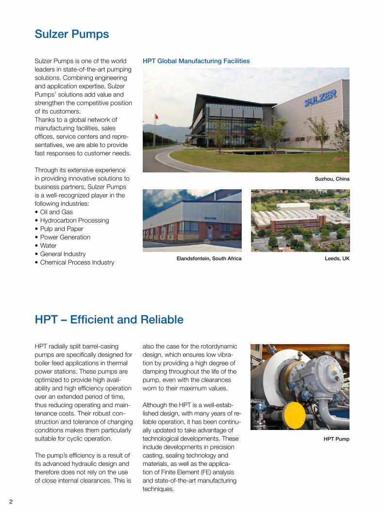
Suzhou, China
Leeds, UK
HPT Pump
Elandsfontein, South Africa
HPT Global Manufacturing Facilities
also the case for the rotordynamic design, which ensures low vibra-tion by providing a high degree of damping throughout the life of the pump, even with the clearances worn to their maximum values.
Although the HPT is a well-estab-lished design, with many years of re-liable operation, it has been continu-ally updated to take advantage of technological developments. These include developments in precision casting, sealing technology and materials, as well as the applica-tion of Finite Element (FE) analysis and state-of-the-art manufacturing techniques.
Sulzer Pumps is one of the world leaders in state-of-the-art pumping solutions. Combining engineering and application expertise, Sulzer Pumps’ solutions add value and strengthen the competitive position of its customers. Thanks to a global network of manufacturing facilities, sales offices, service centers and repre-sentatives, we are able to provide fast responses to customer needs.
Through its extensive experience in providing innovative solu tions to business partners, Sulzer Pumps is a well-recognized player in the following industries:• Oil and Gas• Hydrocarbon Processing• Pulp and Paper• Power Generation• Water• General Industry• Chemical Process Industry
3
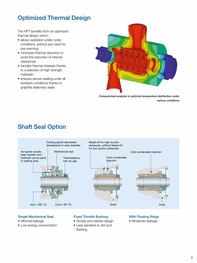
The HPT benefits from an optimized thermal design which:• allows operation under cyclic
conditions, without any need for pre-warming
• minimizes thermal distortion to avoid the reduction of internal clearances
• handles thermal stresses thanks to a selection of high strength materials
• ensures secure sealing under all transient conditions thanks to graphite stationary seals
Shaft Seal Option
Optimized Thermal Design
Computerized analysis to optimize temperature distribution under
various conditions
With Floating Rings• Moderate leakage
Fixed Throttle Bushing• Simple and reliable design• Less sensitive to dirt and
flashing
Single Mechanical Seal• Minimal leakage• Low energy consumption
•
Air barrier avoids heat transfer from hydraulic pump parts to sealing area
Cooling jacket decreases temperature in seal chamber
•
Drain
Bleed-off for high suction pressures, without bleed-off for low suction pressures
Cold condensate injection
Hot (~180 °C)
• •
Cool (~60 °C)
••• •
Mechanical seal
Thermosleeve with air gap
•
Cold condensate injection
Drain
•
4
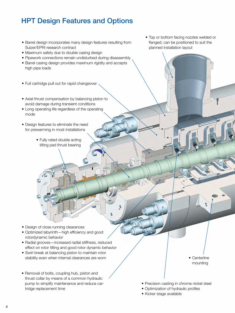
HPT Design Features and Options
• Centerline mounting
• Full cartridge pull out for rapid changeover
• Design features to eliminate the need for prewarming in most installations
• Removal of bolts, coupling hub, piston and thrust collar by means of a common hydraulic pump to simplify maintenance and reduce car-tridge replacement time
• Barrel design incorporates many design features resulting from Sulzer/EPRI research contract
• Maximum safety due to double casing design• Pipework connections remain undisturbed during disassembly• Barrel casing design provides maximum rigidity and accepts
high pipe loads
• Top or bottom facing nozzles welded or flanged; can be positioned to suit the planned installation layout
• Fully rated double acting tilting pad thrust bearing
• Precision casting in chrome nickel steel• Optimization of hydraulic profiles• Kicker stage available
• Axial thrust compensation by balancing piston to avoid damage during transient conditions
• Long operating life regardless of the operating mode
• Design of close running clearances• Optimized labyrinth—high efficiency and good
rotordynamic behavior• Radial grooves—increased radial stiffness, reduced
effect on rotor tilting and good rotor dynamic behavior• Swirl break at balancing piston to maintain rotor
stability even when internal clearances are worn
5
Optional Kicker Stage
••
•
•
•
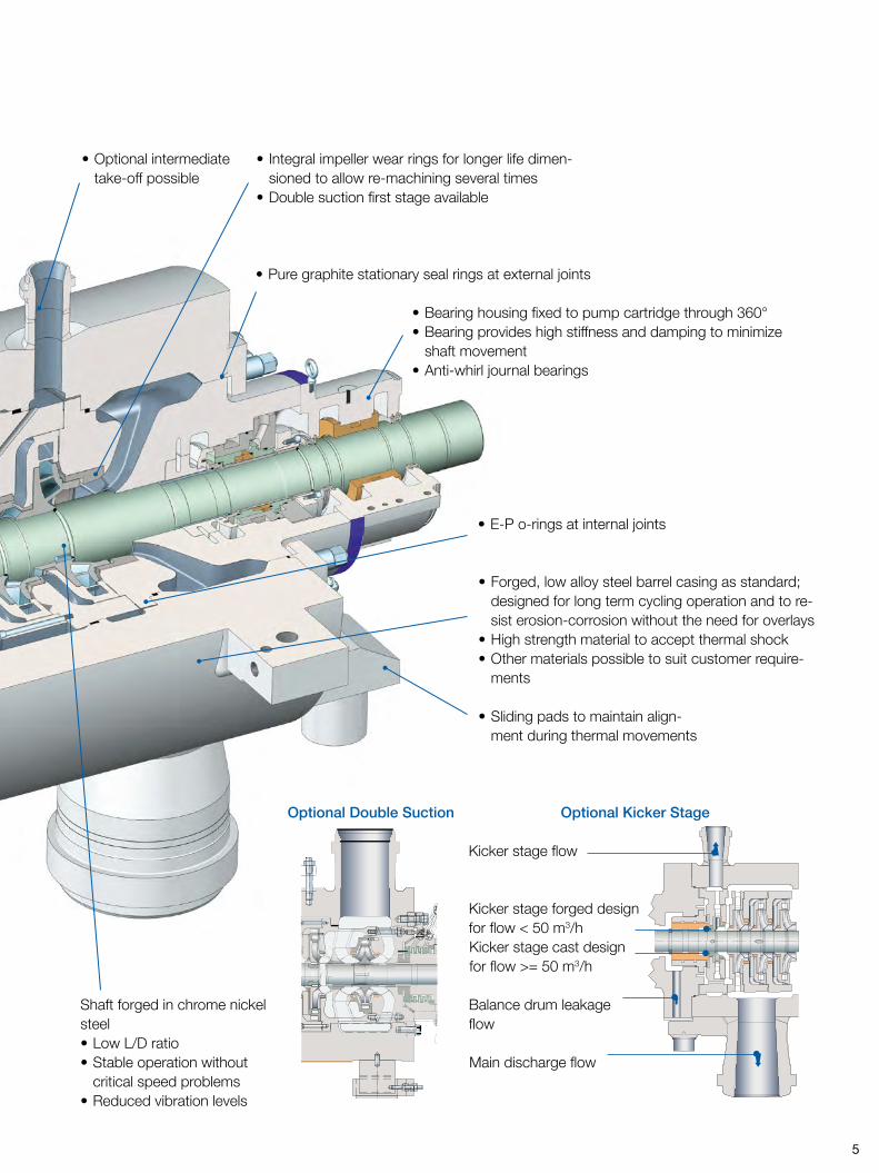
• Optional intermediate take-off possible
• Bearing housing fixed to pump cartridge through 360°• Bearing provides high stiffness and damping to minimize
shaft movement• Anti-whirl journal bearings
• Forged, low alloy steel barrel casing as standard; designed for long term cycling operation and to re-sist erosion-corrosion without the need for overlays
• High strength material to accept thermal shock• Other materials possible to suit customer require-
ments
• Integral impeller wear rings for longer life dimen-sioned to allow re-machining several times
• Double suction first stage available
• Sliding pads to maintain align-ment during thermal movements
• E-P o-rings at internal joints
Shaft forged in chrome nickel steel• Low L/D ratio• Stable operation without
critical speed problems• Reduced vibration levels
• Pure graphite stationary seal rings at external joints
Optional Double Suction
Kicker stage flow
Kicker stage forged design for flow < 50 m3/hKicker stage cast design for flow >= 50 m3/h
Balance drum leakage flow
Main discharge flow
6
HPT Features
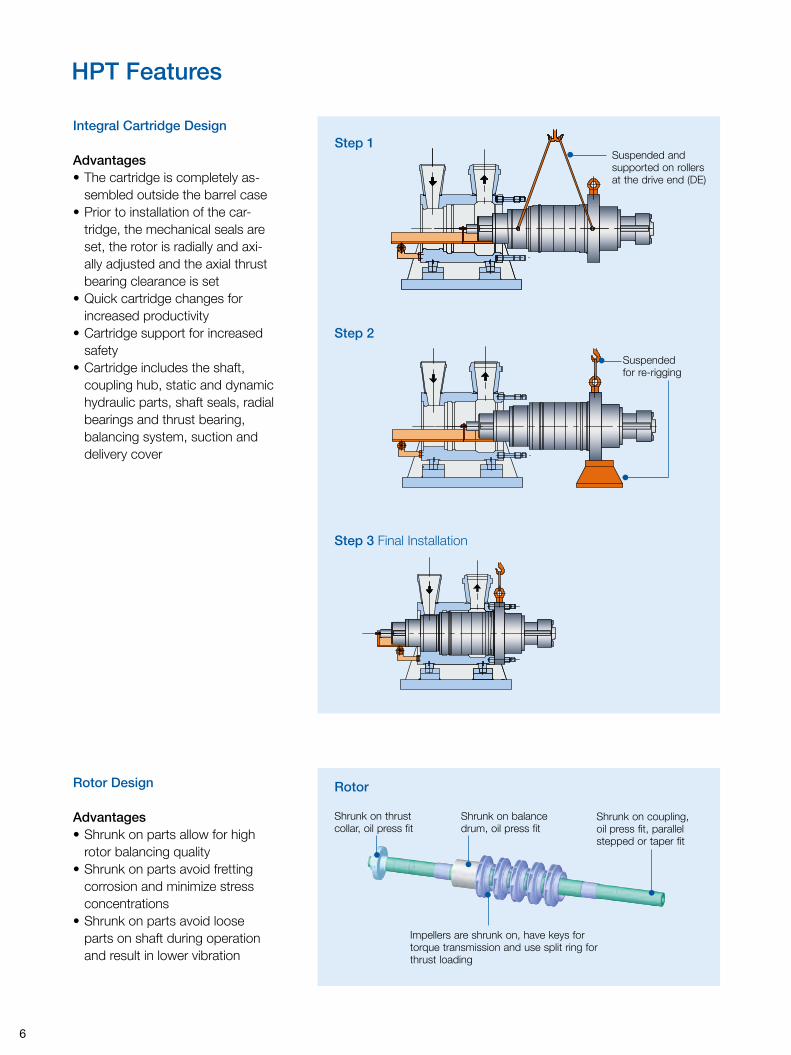
Integral Cartridge Design
Advantages• The cartridge is completely as-
sembled outside the barrel case• Prior to installation of the car-
tridge, the mechanical seals are set, the rotor is radially and axi-ally adjusted and the axial thrust bearing clearance is set
• Quick cartridge changes for increased productivity
• Cartridge support for increased safety
• Cartridge includes the shaft, coupling hub, static and dynamic hydraulic parts, shaft seals, radial bearings and thrust bearing, balancing system, suction and delivery cover
Rotor Design
Advantages• Shrunk on parts allow for high
rotor balancing quality• Shrunk on parts avoid fretting
corrosion and minimize stress concentrations
• Shrunk on parts avoid loose parts on shaft during operation and result in lower vibration
•
Shrunk on coupling, oil press fit, parallel stepped or taper fit
•
Shrunk on balance drum, oil press fit
•
Shrunk on thrust collar, oil press fit
•
Impellers are shrunk on, have keys for torque transmission and use split ring for thrust loading
Step 1Suspended and supported on rollers at the drive end (DE)
•
Step 2
Step 3 Final Installation
Suspended for re-rigging
•
•
Rotor
7
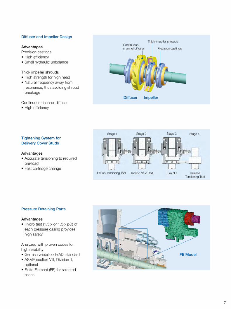
Diffuser and Impeller Design
AdvantagesPrecision castings• High efficiency• Small hydraulic unbalance
Thick impeller shrouds• High strength for high head• Natural frequency away from
resonance, thus avoiding shroud breakage
Continuous channel diffuser• High efficiency
Diffuser
Pressure Retaining Parts
Advantages• Hydro test (1.5 x or 1.3 x pD) of
each pressure casing provides high safety
Analyzed with proven codes for high reliability:• German vessel code AD, standard• ASME section VIII, Division 1,
optional• Finite Element (FE) for selected
cases
FE Model
Tightening System for Delivery Cover Studs
Advantages• Accurate tensioning to required
pre-load• Fast cartridge change
Stage 1 Stage 2 Stage 3 Stage 4
Set up Tensioning Tool Tension Stud Bolt Turn Nut Release Tensioning Tool
Impeller
•
Precision castings
•
Thick impeller shrouds
•
Continuous channel diffuser
Diffuser
8
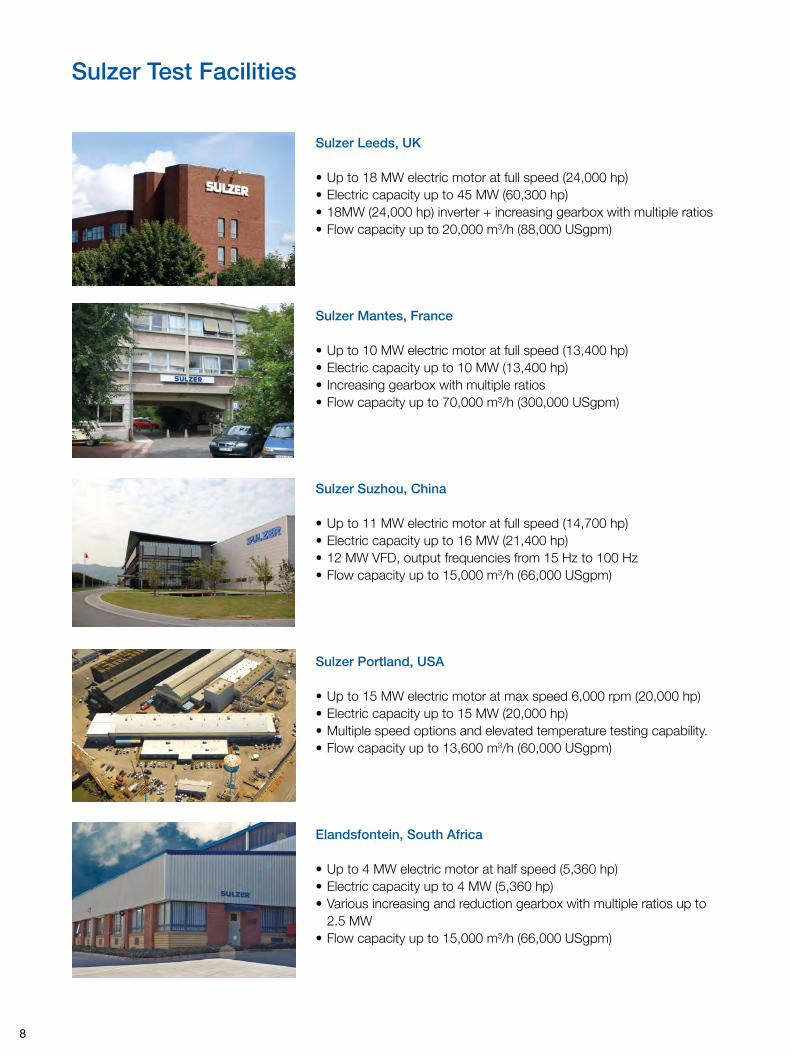
Sulzer Test Facilities
Sulzer Leeds, UK
• Up to 18 MW electric motor at full speed (24,000 hp)• Electric capacity up to 45 MW (60,300 hp)• 18MW (24,000 hp) inverter + increasing gearbox with multiple ratios• Flow capacity up to 20,000 m3/h (88,000 USgpm)
Sulzer Mantes, France
• Up to 10 MW electric motor at full speed (13,400 hp)• Electric capacity up to 10 MW (13,400 hp)• Increasing gearbox with multiple ratios• Flow capacity up to 70,000 m3/h (300,000 USgpm)
Sulzer Suzhou, China
• Up to 11 MW electric motor at full speed (14,700 hp)• Electric capacity up to 16 MW (21,400 hp)• 12 MW VFD, output frequencies from 15 Hz to 100 Hz • Flow capacity up to 15,000 m3/h (66,000 USgpm)
Sulzer Portland, USA
• Up to 15 MW electric motor at max speed 6,000 rpm (20,000 hp)• Electric capacity up to 15 MW (20,000 hp)• Multiple speed options and elevated temperature testing capability.• Flow capacity up to 13,600 m3/h (60,000 USgpm)
Elandsfontein, South Africa
• Up to 4 MW electric motor at half speed (5,360 hp)• Electric capacity up to 4 MW (5,360 hp)• Various increasing and reduction gearbox with multiple ratios up to
2.5 MW• Flow capacity up to 15,000 m3/h (66,000 USgpm)
9
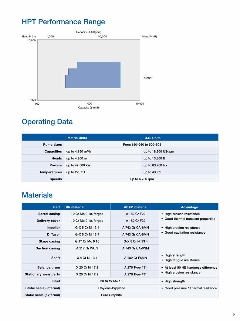
HPT Performance Range
10,000
100 1,000 10,000
Head H (m)
1,000
Capacity Q (m /h)3
Head H (ft)
Capacity Q ( )USgpm
1,000
10,000
10,000
Materials
Operating Data
Part DIN material ASTM material Advantage
Barrel casing 10 Cr Mo 9 10, forged A 182 Gr F22 • High erosion resistance
• Good thermal transient propertiesDelivery cover 10 Cr Mo 9 10, forged A 182 Gr F22
Impeller G-X 5 Cr Ni 13 4 A 743 Gr CA-6MN • High erosion resistance
• Good cavitation resistanceDiffuser G-X 5 Cr Ni 13 4 A 743 Gr CA-6MN
Stage casing G 17 Cr Mo 9 10 G-X 5 Cr Ni 13 4
Suction casing A 217 Gr WC 9 A 743 Gr CA-6NM
Shaft X 4 Cr Ni 13 4 A 182 Gr F6MN• High strength
• High fatigue resistance
Balance drum X 20 Cr Ni 17 2 A 276 Type 431 • At least 50 HB hardness difference
• High erosion resistanceStationary wear parts X 20 Cr Ni 17 2 A 276 Type 431
Stud 36 Ni Cr Mo 16 • High strength
Static seals (internal) Ethylene-Prpylene • Good pressure / Thermal resilience
Static seals (external) Pure Graphite
Metric Units U.S. Units
Pump sizes From 150–260 to 500–505
Capacities up to 4,150 m3/h up to 18,300 USgpm
Heads up to 4,200 m up to 13,800 ft
Powers up to 47,500 kW up to 63,700 hp
Temperatures up to 220 °C up to 430 °F
Speeds up to 6,750 rpm
10
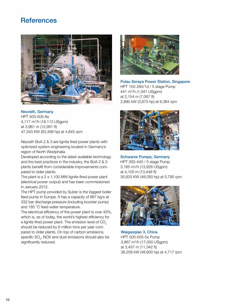
References
Pulau Seraya Power Station, SingaporeHPT 150-260/1d / 5 stage Pump441 m3/h (1,941 USgpm)at 2,154 m (7,067 ft)2,890 kW (3,875 hp) at 6,364 rpm
Neurath, GermanyHPT 500-505-6s4,117 m3/h (18,113 USgpm)at 3,961 m (12,991 ft)47,343 KW (63,488 hp) at 4,845 rpm
Waigaoqiao 3, ChinaHPT 500-505-5s Pump3,867 m3/h (17,050 USgpm)at 3,457 m (11,342 ft)36,258 kW (48,600 hp) at 4,717 rpm
Schwarze Pumpe, GermanyHPT 350-440 / 5 stage Pump 3,165 m3/h (13,926 USgpm)at 4,100 m (13,448 ft)35,833 KW (48,050 hp) at 5,795 rpm
Neurath BoA 2 & 3 are lignite fired power plants with optimized system engineering located in Germany’s region of North Westphalia.Developed according to the latest available technology and the best practices in the industry, the BoA 2 & 3 plants benefit from considerable improvements com-pared to older plants.The plant is a 2 x 1,100 MW lignite-fired power plant (electrical power output) and has been commissioned in January 2012.The HPT pump provided by Sulzer is the biggest boiler feed pump in Europe. It has a capacity of 887 kg/s at 332 bar discharge pressure (including booster pump) and 185 °C feed water temperature.The electrical efficiency of the power plant is over 43%, which is, as of today, the world’s highest efficiency for a lignite fired power plant. The emission level of CO2 should be reduced by 6 million tons per year com-pared to older plants. On top of carbon emissions, specific SO2, NOX and dust emissions should also be significantly reduced.
11
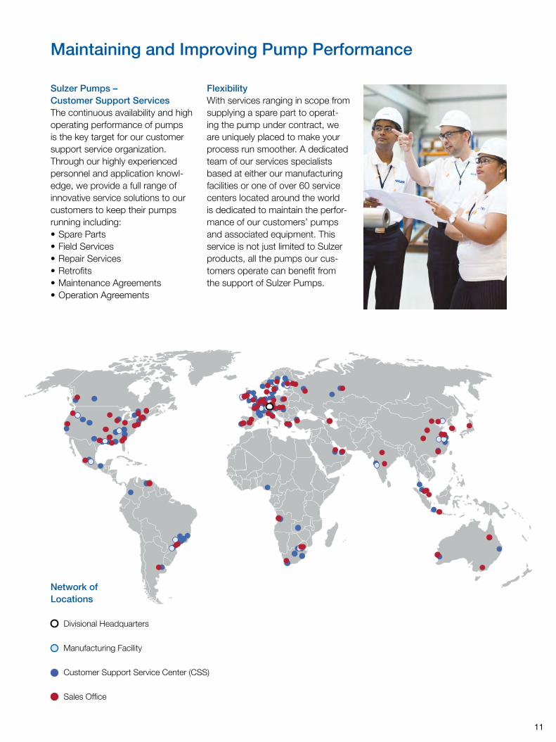
Maintaining and Improving Pump Performance
Sulzer Pumps – Customer Support ServicesThe continuous availability and high operating performance of pumps is the key target for our customer support service organization. Through our highly experienced personnel and application knowl-edge, we provide a full range of innovative service solutions to our customers to keep their pumps running including:• Spare Parts• Field Services• Repair Services• Retrofits• Maintenance Agreements• Operation Agreements
FlexibilityWith services ranging in scope from supplying a spare part to operat-ing the pump under contract, we are uniquely placed to make your process run smoother. A dedicated team of our services specialists based at either our manufacturing facilities or one of over 60 service centers located around the world is dedicated to maintain the perfor-mance of our customers’ pumps and associated equipment. This service is not just limited to Sulzer products, all the pumps our cus-tomers operate can benefit from the support of Sulzer Pumps.
Network of Locations
Divisional Headquarters
Manufacturing Facility
Customer Support Service Center (CSS)
Sales Office

E00616 (2) en 2.2013 (1,000), Copyright © Sulzer PumpsThis brochure is a general presentation. It does not provide any warranty or guarantee of any kind. Please, contact us for a description of the warranties and guarantees offered with our products. Directions for use and safety will be given separately. All information herein is subject to change without notice.
www.sulzer.com